instruction manual lensmeter lm - ایران ممکو · pdf fileintroduction thank you for...
TRANSCRIPT

INSTRUCTION MANUALLENSMETER
LM-8
INTRODUCTION Thank you for your purchase of the TOPCONLENSMETER LM-8.To get the best use of the instrument, be sureto read this Instruction Manual.By thoroughly familiarizing yourself with theinstrument and its operations, you will surelybe able to obtain the full benefit of a superiorprecision optical instrument.Keep this Manual for future reference.
Precautions• As this instrument is a precision equipment, always use it under temperature
and humidity conditions of the normal living environment.• Install this instrument on a level and stable table, and avoid exposure to
direct sunlight.• Keep clean the ambient conditions, and turn off the power source and apply
the dustcover when not in use.• To ensure exact measurement values, take care and keep dust and grease
off the lens and other parts that come into contact with the lens.• We shall not take any responsibility for overhauling and rebuilding without
our permission.• Note that, if this instrument is used in an manner other than that specified
herein, it may spoil the protections provided by devices.
1
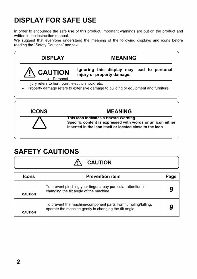
DISPLAY FOR SAFE USEIn order to encourage the safe use of this product, important warnings are put on the product andwritten in the instruction manual.We suggest that everyone understand the meaning of the following displays and icons beforereading the “Safety Cautions” and text.
• Personalinjury refers to hurt, burn, electric shock, etc.
• Property damage refers to extensive damage to building or equipment and furniture.
SAFETY CAUTIONS
Icons Prevention item Page
CAUTION
To prevent pinching your fingers, pay particular attention inchanging the tilt angle of the machine. 9
CAUTION
To prevent the machine/component parts from tumbling/falling,operate the machine gently in changing the tilt angle. 9
2
DISPLAY
ICONS MEANING
CAUTION
MEANING
Ignoring this display may lead to personalinjury or property damage.
CAUTION
This icon indicates a Hazard Warning.Specific content is expressed with words or an icon eitherinserted in the icon itself or located close to the icon
USAGE AND MAINTENANCEUsage:
The Lensmeter is an electric equipment. When using, strictly follow theinstructions in this Manual.
USER MAINTENANCE:To maintain the safety and performance of the equipment, never attempt to do themaintenance of parts specified herein, which should be taken care of by our servicemen.The maintenance items that can be covered by users are the following; for details, followthe instructions.
Target position adjustment (see page 14)
ESCAPE CLAUSE• TOPCON shall not take any responsibility for damages due to fire, earthquake,
actions by third person, or the negligence and missuse by the user and used underunusual conditions.
• TOPCON shall not take any responsibility for damages derived from the inability touse this equipment, such as a loss of business profit and suspension of business.
• TOPCON shall not take any responsibility for damage caused by operations otherthan those described in this Instruction Manual.
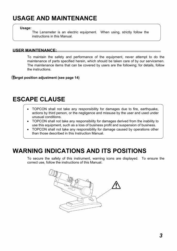
WARNING INDICATIONS AND ITS POSITIONSTo secure the safety of this instrument, warning icons are displayed. To ensure thecorrect use, follow the instructions of this Manual.
3

CONTENT
INTRODUCTION 1
DISPLAY FOR SAFE USE 2
SAFETY PRECAUTIONS 2
USAGE AND MAINTENANCE 3
ESCAPE CLAUSE 3
WARNING INDICATIONS AND 3ITS POSITIONS
COMPONENTS
COMPONENT NAME 5
ACCESSORIES 5
TARGET IMAGE
TARGET IMAGE 6
MEASUREMENT PREPARATIONS
MEASUREMENT PREPARATIONS 7
MEASUREMENT
MEASUREMENT OF 8SPHERICAL LENS
MEASUREMENT OF 8ASTIGMATIC LENS
MEASUREMENT OF FRAMED 9ASTIGMATIC LENS
MEASUREMENT OF CONTACT 9LENS
MEASUREMENT OF 10PRISMATIC LENS
AXIS MARKING 10
PRISM COMPENSATOR
PRISM COMPENSATOR 11
MAINTENANCE
MAINTENANCE 13
CHECK&ADJUSTMENT
CHECK&ADJUSTMENT 14
BEFORE REQUESTING REPAIRING SERVICE
CHECK ITEMS 15
SPECIFICATIONS 15
OPTIONAL ACCESSORIES 15
4

COMPONENTSCOMPONENT NAMES
ACCESSORIES
(A) Contact lens stop .......................... 1 pc.(B) Silicon cloth ................................... 1 pc.(C) Dustcover...................................... 1 pc.(D) UM1 dry cell .................................. 2 pcs.(E) Lens protection pad ...................... 1 set
5COMPONENTS
LM-8E(Diopter power knob with scale)
LM-8C(without axis wheel)
(E)(D)
(B)
(C)
(A)
Lens stop
Protractor ringEyepiece adjustment ring
Lens holder
LM-8Prism holder
Lens table
Axis wheel
Diopter power knob
Tilt locking leverCell box
Lens table adjustment lever
Axis marker lever
Lens holder lever
Power switch
TARGET IMAGE
6TARGET IMAGE
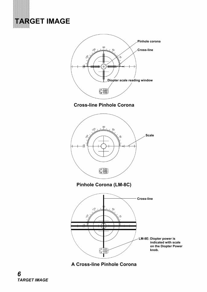
Cross-line Pinhole Corona
Pinhole Corona (LM-8C)
A Cross-line Pinhole Corona
Pinhole corona
Diopter scale reading window
Cross-line
Scale
Cross-line
LM-8E: Diopter power isindicated with scaleon the Diopter Powerknob.
MEASUREMENT PREPARATIONSMEASUREMENT PREPARATIONS
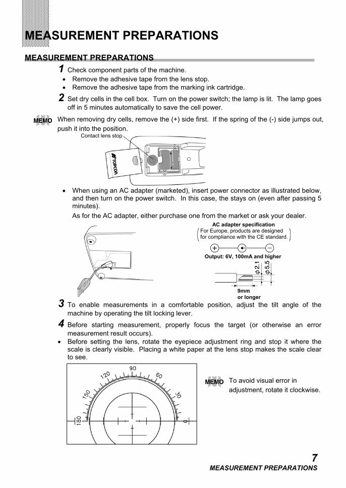
1 Check component parts of the machine.• Remove the adhesive tape from the lens stop.• Remove the adhesive tape from the marking ink cartridge.
2 Set dry cells in the cell box. Turn on the power switch; the lamp is lit. The lamp goesoff in 5 minutes automatically to save the cell power.
• When using an AC adapter (marketed), insert power connector as illustrated below,and then turn on the power switch. In this case, the stays on (even after passing 5minutes).As for the AC adapter, either purchase one from the market or ask your dealer.
3 To enable measurements in a comfortable position, adjust the tilt angle of themachine by operating the tilt locking lever.
4 Before starting measurement, properly focus the target (or otherwise an errormeasurement result occurs).
• Before setting the lens, rotate the eyepiece adjustment ring and stop it where thescale is clearly visible. Placing a white paper at the lens stop makes the scale clearto see.
7MEASUREMENT PREPARATIONS
When removing dry cells, remove the (+) side first. If the spring of the (-) side jumps out,push it into the position.
To avoid visual error inadjustment, rotate it clockwise.
Contact lens stop
AC adapter specificationFor Europe, products are designedfor compliance with the CE standard.
9mmor longer
Output: 6V, 100mA and higher

MEASUREMENTMEASUREMENT OF SPHERICAL LENS
1 Place the concave surface of the lens on the lens stop and fix it firmly with the lensholder.
2 Properly focus the target by rotating the diopter power knob.
3 Read the indicator value on the diopter power scale.
MEASUREMENT OF ASTIGMATIC LENS1 Focus the pinhole corona section of the target by rotating the diopter power knob.
Align the cross-line with the stronger meridian by rotating the axis wheel. (Notapplicable to LM-8C)
LM-8C : Align the scale with the stronger meridian by rotating the protractor ring.
2 Read the diopter power scale and the angle for the meridian direction.
3 Focus the target for the other meridian by rotating the diopter power knob.
8MEASUREMENT
To avoid visual error in adjustment, adjust it in the (+)->(-) direction.
If the scale center does not align with the target image center, the optical center of lens isnot in proper alignment with the optical axis of lensmeter. Vertical displacement can beadjusted by pushing the lens toward the lens table by operating the lens table adjustmentlever, and horizontal displacement can be adjusted by moving the lens laterally by hand.
Meridian direction
Meridian direction
Read the diopter power scale and angle.Of these 2 measurement values, take the smaller one in absolute value as the S(spherical) power, and the difference as the C (cylindrical) power. Also, for the axialangle, take the angle of a measurement value of which the absolute value is the larger.
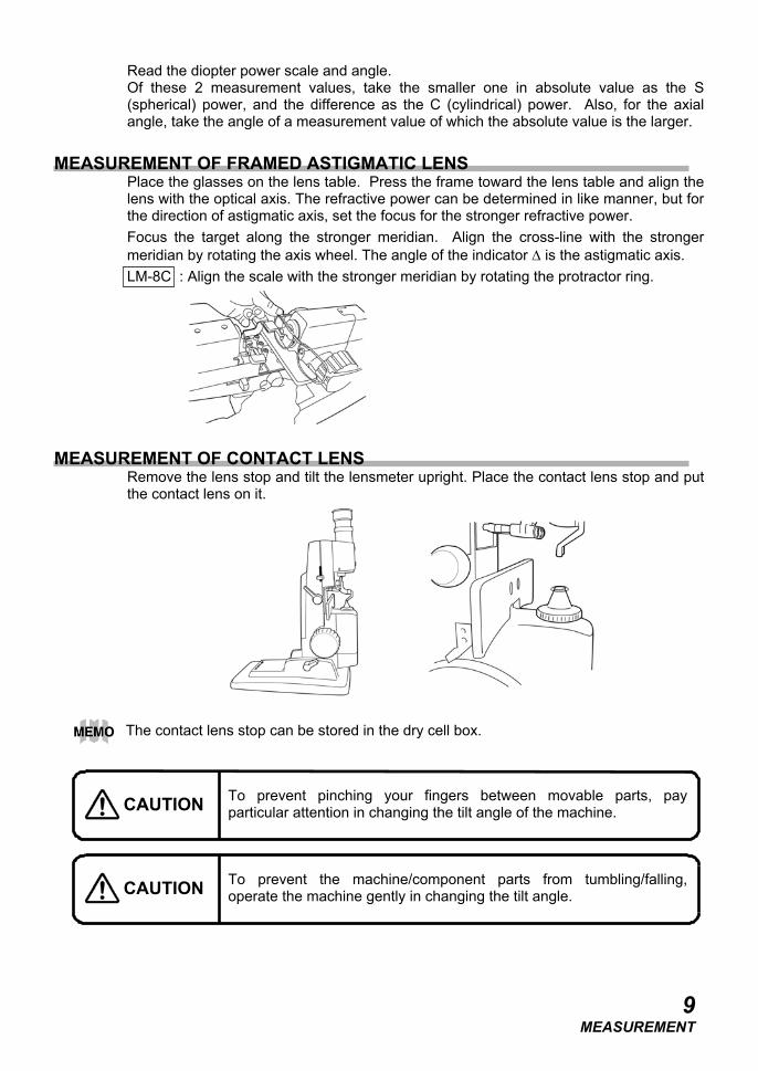
MEASUREMENT OF FRAMED ASTIGMATIC LENSPlace the glasses on the lens table. Press the frame toward the lens table and align thelens with the optical axis. The refractive power can be determined in like manner, but forthe direction of astigmatic axis, set the focus for the stronger refractive power.Focus the target along the stronger meridian. Align the cross-line with the strongermeridian by rotating the axis wheel. The angle of the indicator ∆ is the astigmatic axis.LM-8C : Align the scale with the stronger meridian by rotating the protractor ring.
MEASUREMENT OF CONTACT LENSRemove the lens stop and tilt the lensmeter upright. Place the contact lens stop and putthe contact lens on it.
9MEASUREMENT
The contact lens stop can be stored in the dry cell box.
To prevent pinching your fingers between movable parts, payparticular attention in changing the tilt angle of the machine.
To prevent the machine/component parts from tumbling/falling,operate the machine gently in changing the tilt angle.
CAUTION
CAUTION
MEASUREMENT OF PRISMATIC LENS
Non-astigmatic Lens
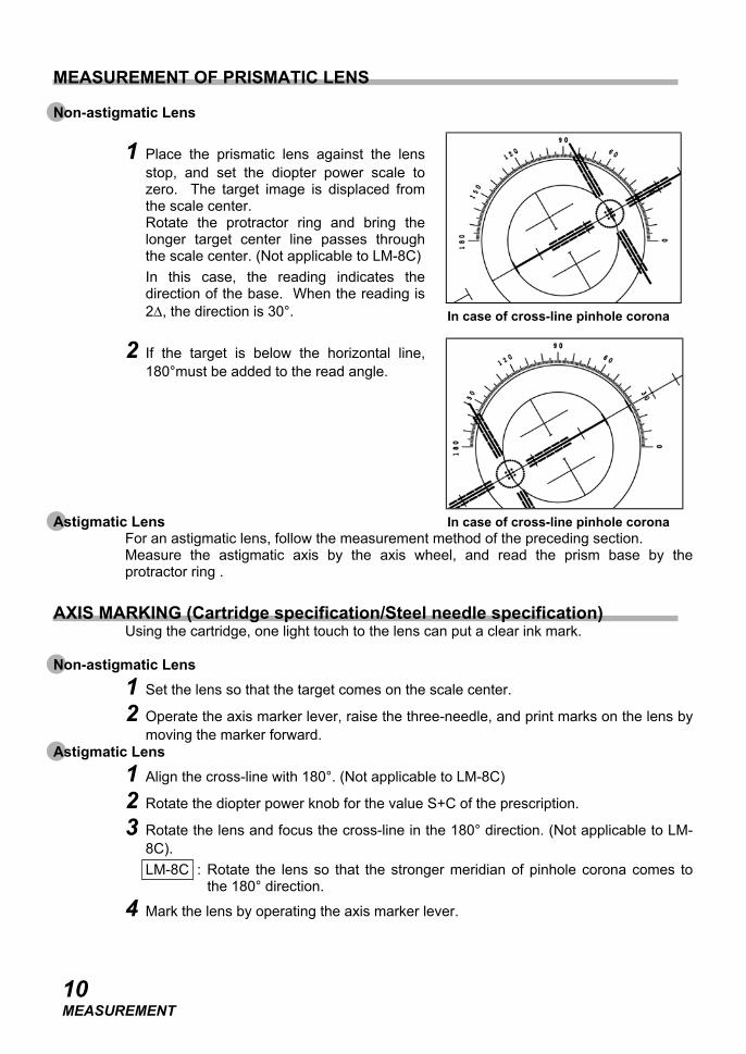
1 Place the prismatic lens against the lensstop, and set the diopter power scale tozero. The target image is displaced fromthe scale center.Rotate the protractor ring and bring thelonger target center line passes throughthe scale center. (Not applicable to LM-8C)In this case, the reading indicates thedirection of the base. When the reading is2∆, the direction is 30°.
2 If the target is below the horizontal line,180°must be added to the read angle.
Astigmatic LensFor an astigmatic lens, follow the measurement method of the preceding section.Measure the astigmatic axis by the axis wheel, and read the prism base by theprotractor ring .
AXIS MARKING (Cartridge specification/Steel needle specification)Using the cartridge, one light touch to the lens can put a clear ink mark.
Non-astigmatic Lens1 Set the lens so that the target comes on the scale center.
2 Operate the axis marker lever, raise the three-needle, and print marks on the lens bymoving the marker forward.
Astigmatic Lens1 Align the cross-line with 180°. (Not applicable to LM-8C)
2 Rotate the diopter power knob for the value S+C of the prescription.
3 Rotate the lens and focus the cross-line in the 180° direction. (Not applicable to LM-8C).LM-8C : Rotate the lens so that the stronger meridian of pinhole corona comes to
the 180° direction.
4 Mark the lens by operating the axis marker lever.
10MEASUREMENT
In case of cross-line pinhole corona
In case of cross-line pinhole corona
PRISM COMPENSATOR(OPTIONAL ACCESSORY: FOR CERTAIN SPECIFICATIONS, THIS ISATTACHED AS STANDARD EQUIPMENT.)
PRISM COMPENSATOR1 It is not impossible to measure lenses corrected for phoria over 6 prism diopters, as
well as segments in spherical lenses of extreme strength, because the corona targetwill be displaced completely out of the field of view of the eyepiece, in this case. Forsuch lenses, the prism compensator must be put into use.
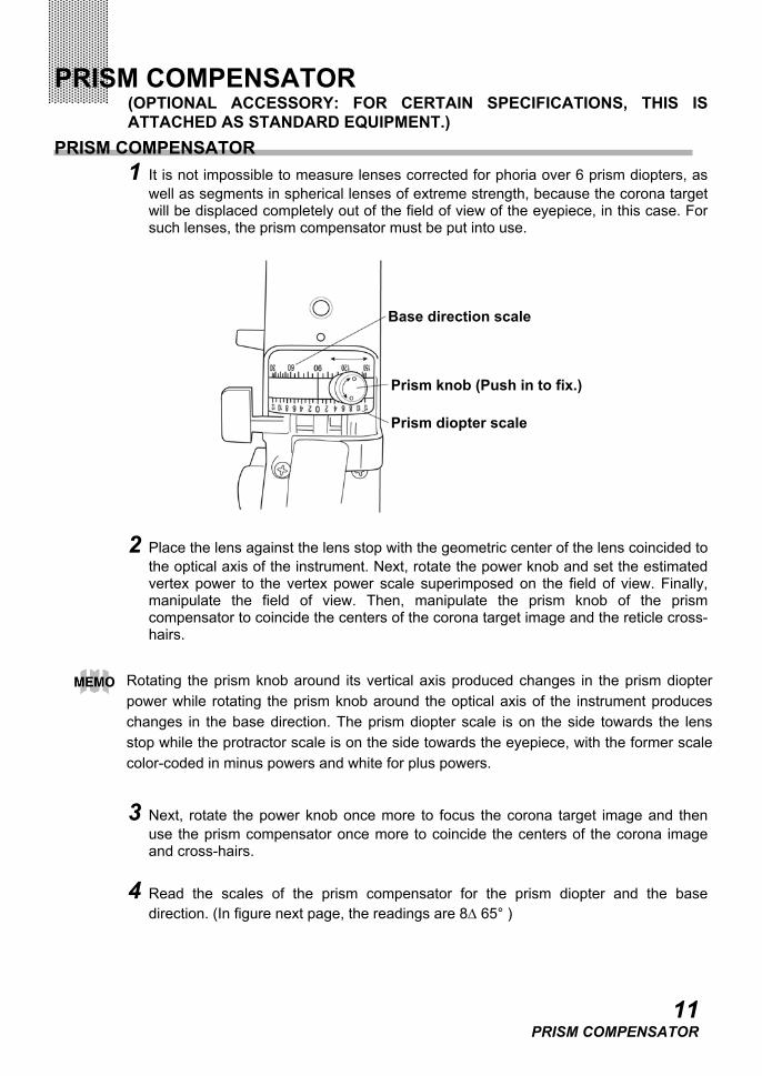
2 Place the lens against the lens stop with the geometric center of the lens coincided tothe optical axis of the instrument. Next, rotate the power knob and set the estimatedvertex power to the vertex power scale superimposed on the field of view. Finally,manipulate the field of view. Then, manipulate the prism knob of the prismcompensator to coincide the centers of the corona target image and the reticle cross-hairs.
3 Next, rotate the power knob once more to focus the corona target image and thenuse the prism compensator once more to coincide the centers of the corona imageand cross-hairs.
4 Read the scales of the prism compensator for the prism diopter and the basedirection. (In figure next page, the readings are 8∆ 65° )
11PRISM COMPENSATOR
Rotating the prism knob around its vertical axis produced changes in the prism diopterpower while rotating the prism knob around the optical axis of the instrument produceschanges in the base direction. The prism diopter scale is on the side towards the lensstop while the protractor scale is on the side towards the eyepiece, with the former scalecolor-coded in minus powers and white for plus powers.
Prism diopter scale
Prism knob (Push in to fix.)
Base direction scale
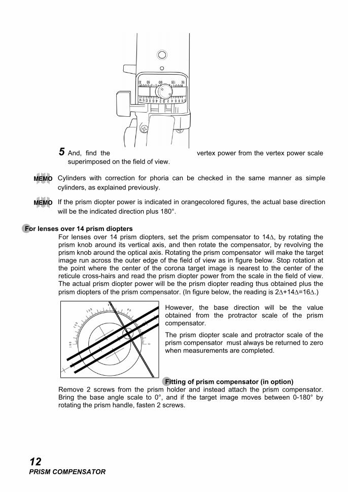
5 And, find the vertex power from the vertex power scalesuperimposed on the field of view.
For lenses over 14 prism dioptersFor lenses over 14 prism diopters, set the prism compensator to 14∆, by rotating theprism knob around its vertical axis, and then rotate the compensator, by revolving theprism knob around the optical axis. Rotating the prism compensator will make the targetimage run across the outer edge of the field of view as in figure below. Stop rotation atthe point where the center of the corona target image is nearest to the center of thereticule cross-hairs and read the prism diopter power from the scale in the field of view.The actual prism diopter power will be the prism diopter reading thus obtained plus theprism diopters of the prism compensator. (In figure below, the reading is 2∆+14∆=16∆.)
However, the base direction will be the valueobtained from the protractor scale of the prismcompensator.
The prism diopter scale and protractor scale of theprism compensator must always be returned to zerowhen measurements are completed.
Fitting of prism compensator (in option)Remove 2 screws from the prism holder and instead attach the prism compensator.Bring the base angle scale to 0°, and if the target image moves between 0-180° byrotating the prism handle, fasten 2 screws.
12PRISM COMPENSATOR
Cylinders with correction for phoria can be checked in the same manner as simplecylinders, as explained previously.
If the prism diopter power is indicated in orangecolored figures, the actual base directionwill be the indicated direction plus 180°.

MAINTENANCEReplacement of Marking Ink Cartridge
1 To replace the marking ink cartridge, remove the screw from the top. Hold thecartridge when removing so as the spring not to jump out.Do this operation with the lens holder lowered.
Refilling of ink for steel needle (option)1 When ink becomes blurred, refill ink.
2 Slide out the ink pad.
3 Remove the ink pad cover. Pull it in the lengthdirection.
4 Refill ink. Amply supply ink to the felt.
Storage (When not in use)When the machine is not used for a long period, turn off the power switch and cover theattached dustcover.
Cleaning1 Wipe clean the machine with the attached silicon cloth or a dry, soft cloth.
2 Never use solvents (benzine, thinner, etc.) and chemical dusters.
13MAINTENANCE
Ensure the inkcartridges do notinterfere with thelens table
Screw
Marking ink holder
Steel needle(optional accessory)
Markingink cartridge
Spring
CHECK AND ADJUSTMENTSince this machine is a precision optical instrument, use with particular care to keep itfree of shocks and vibrations.
Handling of lens stop (the same for lens holder end)To protect the lens surface, clean the lens stop end and lens holder end and thoroughlyremove adhering dust.Lens protection pad is also attached. However, for a highly spherical lens, themeasurement value shifts a little:
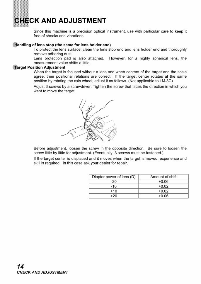
Target Position AdjustmentWhen the target is focused without a lens and when centers of the target and the scaleagree, their positional relations are correct. If the target center rotates at the sameposition by rotating the axis wheel, adjust it as follows. (Not applicable to LM-8C)Adjust 3 screws by a screwdriver. Tighten the screw that faces the direction in which youwant to move the target.
Before adjustment, loosen the screw in the opposite direction. Be sure to loosen thescrew little by little for adjustment. (Eventually, 3 screws must be fastened.)If the target center is displaced and it moves when the target is moved, experience andskill is required. In this case ask your dealer for repair.
Diopter power of lens (D) Amount of shift-20 +0.06-10 +0.02+10 +0.02+20 +0.06
14CHECK AND ADJUSTMENT
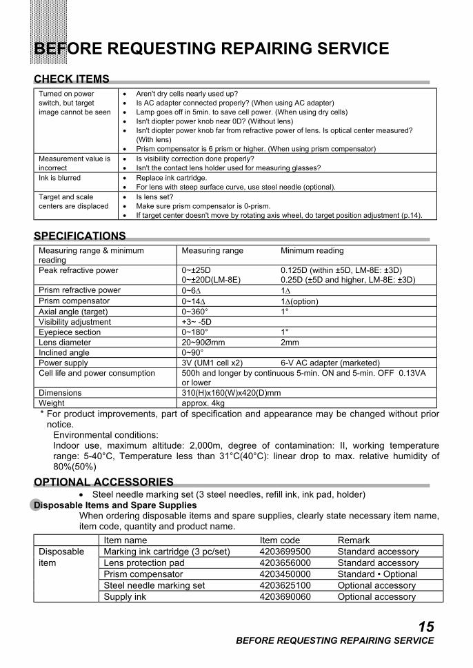
BEFORE REQUESTING REPAIRING SERVICECHECK ITEMS
Turned on powerswitch, but targetimage cannot be seen
• Aren't dry cells nearly used up?• Is AC adapter connected properly? (When using AC adapter)• Lamp goes off in 5min. to save cell power. (When using dry cells)• Isn't diopter power knob near 0D? (Without lens)• Isn't diopter power knob far from refractive power of lens. Is optical center measured?
(With lens)• Prism compensator is 6 prism or higher. (When using prism compensator)
Measurement value isincorrect
• Is visibility correction done properly?• Isn't the contact lens holder used for measuring glasses?
Ink is blurred • Replace ink cartridge.• For lens with steep surface curve, use steel needle (optional).
Target and scalecenters are displaced
• Is lens set?• Make sure prism compensator is 0-prism.• If target center doesn't move by rotating axis wheel, do target position adjustment (p.14).
SPECIFICATIONSMeasuring range & minimumreading
Measuring range Minimum reading
Peak refractive power 0~±25D 0.125D (within ±5D, LM-8E: ±3D)0~±20D(LM-8E) 0.25D (±5D and higher, LM-8E: ±3D)
Prism refractive power 0~6∆ 1∆Prism compensator 0~14∆ 1∆(option)Axial angle (target) 0~360° 1°Visibility adjustment +3~ -5DEyepiece section 0~180° 1°Lens diameter 20~90Ømm 2mmInclined angle 0~90°Power supply 3V (UM1 cell x2) 6-V AC adapter (marketed)Cell life and power consumption 500h and longer by continuous 5-min. ON and 5-min. OFF 0.13VA
or lowerDimensions 310(H)x160(W)x420(D)mmWeight approx. 4kg* For product improvements, part of specification and appearance may be changed without prior
notice.Environmental conditions:Indoor use, maximum altitude: 2,000m, degree of contamination: II, working temperaturerange: 5-40°C, Temperature less than 31°C(40°C): linear drop to max. relative humidity of80%(50%)
OPTIONAL ACCESSORIES• Steel needle marking set (3 steel needles, refill ink, ink pad, holder)
Disposable Items and Spare SuppliesWhen ordering disposable items and spare supplies, clearly state necessary item name,item code, quantity and product name.
Item name Item code RemarkDisposable Marking ink cartridge (3 pc/set) 4203699500 Standard accessoryitem Lens protection pad 4203656000 Standard accessory
Prism compensator 4203450000 Standard • OptionalSteel needle marking set 4203625100 Optional accessorySupply ink 4203690060 Optional accessory
15BEFORE REQUESTING REPAIRING SERVICE

LENSMETER
LM-8
TOPCON AMERICA CORPORATIONCORPORATE OFFICE:37, West Century Road, Paramus, New Jersey 07652, U.S.A. Phone: 201-261-9450 Fax: 201-387-2710
TOPCON OMNI SYSTEMS, INC.Valley Forge Business Center, 2430 Blvd. of the Generals, Norristown, PA 19403, U.S.A Phone: 610-630-9200 Fax: 610-630-6428
TOPCON EUROPE B.V.(European Representative)Esse Baan 11, 2908 LJ Capelle a/d IJssel, The Netherlands. Phone: 010-4585077 Fax: 010-4585045
TOPCON S.A.R.L.HEAD OFFICE:104/106, Rue Rivay 92300, Levallois-Perret, France. Phone: 01-41069494 Fax: 01-47390251LYON OFFICE:138, Avenue du 8 Mai 1945, 69100 Villeurbanne, France Phone: 0478688237 Fax: 0478681902TOPCON DEUTSCHLAND G.m.b.H.Halskestr. 7, 47877 Willich, Germany. Phone: 02154-9290 Fax: 02154-929-111 Telex: 8531981 TOPC D
TOPCON ESPAÑA S.A.HEAD OFFICE:Frederic Mompou 5, 08960 Sant Just Desvern Barcelona, Spain. Phone: 03-4734057 Fax: 03-4733932MADRID OFFICE:Avenida Ciudad de Barcelona 81, 1 Planta 28007, Madrid, Spain. Phone: 01-552-4160 Fax: 01-552-4161TOPCON SCANDINAVIA A. B.Industrivägen 4 P. O. Box 2140 43302 Sävedalen Sweden. Phone: 031-261250 Fax: 031-268607TOPCON (GREAT BRITAIN) LTD.Topcon House,Kennet Side,Bone Lane,Newbury,Berkshire RG14 5PX United Kingdom Phone:01635-551120 Fax:01635-551170
TOPCON SINGAPORE PTE. LTD.Alexandra Distripark Block 4, #05-15, Pasir Panjang Road, Singapore 118491 Phone: 2780222 Fax: 2733540 Telex: 61121 TOPSIN
TOPCON INSTRUMENTS (MALAYSIA) SDN. BHD.Lot 226 Jalan Negara 2, Pusat Bandar Taman Melawati, Taman Melawati, 53100, Kuala Lumpur, Malaysia. Phone: 03-4079801 Fax: 03-4079796TOPCON INSTRUMENTS (THAILAND) CO., LTD.77/162 Sinn Sathorn Tower, 37th Fl.,Krungdhonburi Rd.,Klongtonsai, Klongsarn, Bangkok 10600 Phone: 662-440-1152~7 Fax: 662-440-1158
TOPCON AUSTRALIA PTY. LTD.408 Victoria Road, Gladesville, NSW 2111, Australia Phone: 02-9817-4666 Fax: 02-9817-4654
TOPCON KOREA CORPORATIONHyobong Bldg., 1-1306, Seocho-Dong, Seocho-Gu, Seoul, Korea. Phone: 02-557-9231~2 Fax: 02-556-1928 Telex: K23231 EXT2264
TOPCON OPTICAL (H.K.) LIMITED2-4/F Meeco Industrial Bldg, No. 53-55 Au Pui Wan Street, Fo Tan Road,Shatin, N.T., Hong Kong Phone: 26901328 Fax: 26910264
TOPCON CORPORATION BEIJING OFFICERoom No. 962 Poly Plaza Building, 14 Dongzhimen Nandajie Dongcheng District, Beijing, 100027, China Phone: 10-6501-4191~2 Fax: 10-6501-4190
TOPCON CORPORATION BEIRUT OFFICEP. O. BOX 70-1002 Antelias, BEIRUT-LEBANON. Phone: 961-1-521119 Fax: 961-1-521119
TOPCON CORPORATION DUBAI OFFICEOffice No.102, KHALAF RASHD AL NAYLI BLDG., Deira, Dubai, UAE Phone: 971-4-696511 Fax: 971-4-695272
TOPCON CORPORATION75-1 Hasunuma-cho,Itabashi-ku,Tokyo,174-8580 Japan.Phone:3-3558-2520 Fax:3-3960-4214