operation manual for spectrometer spectro-v11d
TRANSCRIPT
PLEASE READ THIS MANUAL CAREFULLY BEFORE OPERATION
3, Hagavish st. Israel 58817 Tel: 972 3 5595252, Fax: 972 3 5594529 [email protected]
MRC.VER.01-5.12
Operation Manual for SPECTROMETER
SPECTRO-V11D

- 1 -
Contents
Safety ……….……………………………………………………………………. 1
General …………………………………………….…….………………………. 1
Electrical ………………………………………………..……………………….. 1
Warning ………………………………………….…….………………………… 1
Working Principle…..………………………….………………………………… 2
Unpacking Instructions ……………………………….………………………… 3
Specifications…..…………………………………………..…..……….……………3
Installation …………………………………………………………..………………. 4
Instrument Introduction………………………………………….…………………..4
Appearance……………………………………………………………………….4
Operating Panel…………………………………………………………………..5
Button Description………………………………………………………..……...6
Instrument Operation…………………….……………………….….…..………….6
Local Software Structure…………… ………………….….…....…………….6
Basic operation……………………………………….………..……………….6
Measurement………..…………………………………………….…………………7
Measure the Absorbance…………………………………….…..…..............7
Measure the Transmittance……………………………………………………8
Two-points Method……………………………………………………………..9
Coefficient Method……………………………………………………………...10
Troubleshooting……………………………………………….…….………..………22

- 1 -
Safety: The safety statements in this manual comply with the requirements of the HEALTH AND SAFETY AT WORK ACT, 1974. Read the following before installing and using the instrument and its accessories. The MRC SPECTRO-V11D should be operated by appropriate laboratory technicians.
General: The apparatus described in this manual is designed to be used by properly trained personnel in a suitable equipped laboratory. For the correct and safe use of this apparatus it is essential that laboratory personnel follow generally accepted safe procedures in addition to the safety precautions called for in this manual. The covers on this instrument may be removed for servicing. However, the inside of the power supply unit is a hazardous area and its cover should not be removed under any circumstances. There are no serviceable components inside this power supply unit. For MRC SPECTRO-V11D, avoid touching the high voltage power supply at all times. Some of the chemicals used in spectrophotometer are corrosive and/or inflammable and samples may be radioactive, toxic, or potentially infective. Care should be taken to follow the normal laboratory procedures for handling chemicals and samples.
Electrical: The power requirement of SPECTRO-V11D is from 85V to 265V. Make sure that the local power supply is within this range.
The power cord shall be inserted in a socket provided with a protective earth contact. The protective action must not be negated by the use of an extension cord without a protective conductor.
Warning: Any interruption of the protective conductor inside or outside the apparatus or disconnection of the protective earth terminal is likely to make the apparatus dangerous. Intentional interruption is prohibited. Whenever it is likely that the protection has been impaired, the apparatus shall be made inoperative and be secured against any unintended operation. NEVER touch or handle the power supply on MRC SPECTRO-V11D due to the high voltage. The protection is likely to be impaired if, for example, the apparatus
- 2 -
� Shows visible damage � Fails to perform the intended measurements � Has been subjected to prolonged storage under unfavorable conditions � Has been subjected to severe transport stresses
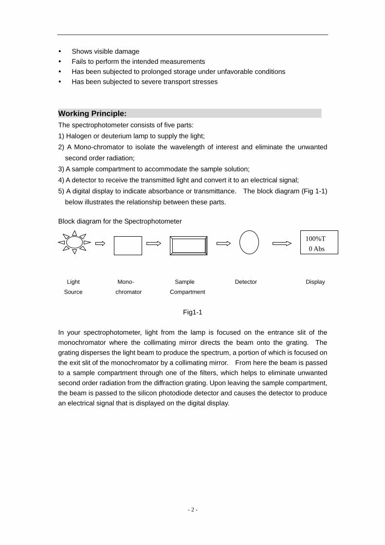
Working Principle: The spectrophotometer consists of five parts: 1) Halogen or deuterium lamp to supply the light; 2) A Mono-chromator to isolate the wavelength of interest and eliminate the unwanted
second order radiation; 3) A sample compartment to accommodate the sample solution; 4) A detector to receive the transmitted light and convert it to an electrical signal; 5) A digital display to indicate absorbance or transmittance. The block diagram (Fig 1-1)
below illustrates the relationship between these parts. Block diagram for the Spectrophotometer
Light Mono- Sample Detector Display
Source chromator Compartment
Fig1-1
In your spectrophotometer, light from the lamp is focused on the entrance slit of the monochromator where the collimating mirror directs the beam onto the grating. The grating disperses the light beam to produce the spectrum, a portion of which is focused on the exit slit of the monochromator by a collimating mirror. From here the beam is passed to a sample compartment through one of the filters, which helps to eliminate unwanted second order radiation from the diffraction grating. Upon leaving the sample compartment, the beam is passed to the silicon photodiode detector and causes the detector to produce an electrical signal that is displayed on the digital display.
100%T 0 Abs
- 3 -
Unpacking Instructions: Carefully unpack the contents and check the materials against the following packing list to ensure that you have received everything in good condition.
Packing List Description Quantity
� Spectrophotometer ............................................................. 1
� Mains Lead ........................................................................... 1
� Cuvettes................................................................................ 1 Set of 4, glass � Manual .................................................................................. 1
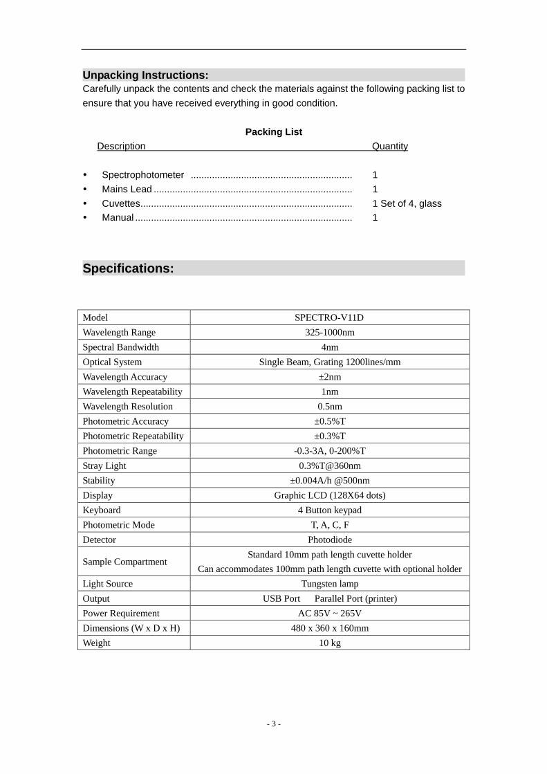
Specifications:
Model SPECTRO-V11D Wavelength Range 325-1000nm Spectral Bandwidth 4nm Optical System Single Beam, Grating 1200lines/mm Wavelength Accuracy ±2nm Wavelength Repeatability 1nm Wavelength Resolution 0.5nm Photometric Accuracy ±0.5%T Photometric Repeatability ±0.3%T Photometric Range -0.3-3A, 0-200%T Stray Light 0.3%T@360nm Stability ±0.004A/h @500nm Display Graphic LCD (128X64 dots) Keyboard 4 Button keypad Photometric Mode T, A, C, F Detector Photodiode
Sample Compartment Standard 10mm path length cuvette holder
Can accommodates 100mm path length cuvette with optional holder Light Source Tungsten lamp Output USB Port Parallel Port (printer) Power Requirement AC 85V ~ 265V Dimensions (W x D x H) 480 x 360 x 160mm Weight 10 kg

- 4 -
Installation:
1) After carefully unpacking the contents, check the materials with the packing list (page 3) to ensure that you have received everything in good condition.
2) Place the instrument in a suitable location away from direct sunlight. 3) In order to have the best performance from your instrument, keep it as far as possible
from any strong magnetic or electrical fields or any electrical device that may generate high-frequency fields.
4) Set the unit up in an area that is free of dust, corrosive gases and strong vibrations. 5) Remove any obstructions or materials that could hinder the flow of air under and
around the instrument. 6) Use the appropriate power cord and plug into a grounded outlet. 7) Turn on the instrument of SPECTRO-V11D, it begins to self test. After that and 20min. ̀
pre-warm, you can take any readings.
NOTE:
This symbol means Caution, Risk of Danger.
Instrument Introduction
1. Appearance Please See Figure 3-1:
Main View

- 5 -
Backside Fig. 3-1
1 — Lid of the compartment 2 — Cell Holder 3 — Pole 4 — Operating Panel 5 — Wavelength Knob 6 — USB Port 7 — Print Port 8 — Fan Cover 9 — Power Socket 10— Power Switch
2. Operating Panel Please see the panel of SPECTRO-V11D (Fig. 3-2)
Fig. 3-2

- 6 -
1 — LCD (128 X 64) 2 — Key Button
3. Button Description
Switch the Photometric Mode
Confirm/Print
Decrease Number/Set Zero
Increase Number/Set 100%T
Instrument Operation
1. Local Software Structure
Please see Fig. 4-1:
图 4-1
2. BASIC OPERATION
1) Select Test Mode
Press to select the test mode. 2) Set Wavelength
Turn the Wavelength Setting Knob to select the wavelength you want, the wavelength Value can be displayed on the screen in real-time.
3) Input the Coefficient
When the system prompts you to input C, k or b, press or button to
change the value till it displays the one you want, then press to confirm. Note: The system will memorize your last input all the time until you input another value.
4) Calibrate Zero

- 7 -
Close the lid of the compartment and press to calibrate Zero. 5) Calibrate 100%T
Pull the Reference in the light path, press to calibrate 100%T。
6) Print the result
Press the Button of to print the test result.
Measurement
1. Measure the Absorbance
1) Press to choose A mode (Fig.4-1);
Fig. 4-1
2) Turn the wavelength knob till it displays the wavelength value you want.
3) Pull the Reference in the light path, press to set 100%T(Fig.4-2);
Fig. 4-2
4) Pull the unknown concentration sample in the light path,then record the displayed value
(Fig. 4-3)。

- 8 -
Fig. 4-3
5) Press to print the test result;
6) Repeat Step 4) and step 5) to test other unknown concentration samples. 2. Measure the Transmittance
1) Press to choose the mode of “T”(Fig. 4-4);
Fig. 4-4
2) Turn the Wavelength Knob to set the wavelength at the point you want;
3) Pull the Reference in the light path,press to calibrate 100%T(Fig. 4-5);
Fig. 4-5
4) Pull the Unknown Concentration Sample in the light path, then the value displayed on the
screen is the one you need.(Fig. 4-6)。

- 9 -
Fig. 4-6
5) Press to print the test result;
6) Repeat step 4 and step 5 to test other samples. 3. Two-point Method
If you have known a Standard Sample’s concentration, and you want to know another sample’s concentration, you can use this method. 1) Choose “A” or “T” Mode and turn the wavelength knob to set the wavelength.
2) Pull the Reference into the light path, press to get 100%T;
3) Pull the Standard sample into the light path and press to choose “C”mode.
4) Press or to input the Standard Sample’s Concentration,
press to confirm. (Fig. 4-7)
Fig. 4-7
5) Pull the unknown concentration sample in the light path, then its concentration displays
on the screen. (Fig.4-8);

- 10 -
Fig. 4-8
6) Press to print the test result. 7) Repeat step5) and step 6) to test other samples.
4. Coefficient Method
1) Turn the Wavelength Knob to set the wavelength at the point you need.
2) Press to choose“F” Mode.
3) Press or to set the coefficient value of K and B, followed with
pressed to confirm. (Fig. 4-9) Then you can test the samples as the following steps..
Fig. 4-9
4) Pull the Reference in the light path and press to set 100%T(Fig. 4-10);
Fig. 4-10
- 11 -
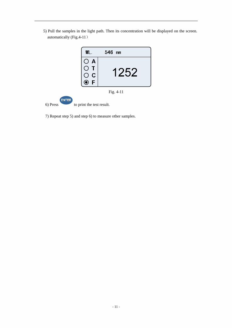
5) Pull the samples in the light path. Then its concentration will be displayed on the screen. automatically (Fig.4-11)
Fig. 4-11
6) Press to print the test result. 7) Repeat step 5) and step 6) to measure other samples.
- 12 -
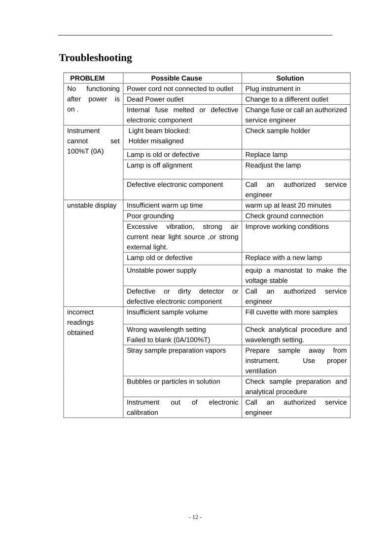
Troubleshooting
PROBLEM Possible Cause Solution
Power cord not connected to outlet Plug instrument in Dead Power outlet Change to a different outlet
No functioning after power is on . Internal fuse melted or defective
electronic component Change fuse or call an authorized service engineer
Light beam blocked: Holder misaligned
Check sample holder
Lamp is old or defective Replace lamp Lamp is off alignment Readjust the lamp
Instrument cannot set 100%T (0A)
Defective electronic component Call an authorized service engineer
Insufficient warm up time warm up at least 20 minutes Poor grounding Check ground connection Excessive vibration, strong air current near light source ,or strong external light.
Improve working conditions
Lamp old or defective Replace with a new lamp
Unstable power supply equip a manostat to make the voltage stable
unstable display
Defective or dirty detector or defective electronic component
Call an authorized service engineer
Insufficient sample volume Fill cuvette with more samples
Wrong wavelength setting Failed to blank (0A/100%T)
Check analytical procedure and wavelength setting.
Stray sample preparation vapors Prepare sample away from instrument. Use proper ventilation
Bubbles or particles in solution Check sample preparation and analytical procedure
incorrect readings obtained
Instrument out of electronic calibration
Call an authorized service engineer