operation layer 2 switching hub manual model no. … · 2 the target model for this operation...
TRANSCRIPT
Operation Manual
for Web Interface
Layer 2 Switching Hub
Model No. PN28058/PN28088
/PN28128/PN28168/PN28248
Thank you for purchasing our product.
This manual provides important information about safe and proper operations
of this switch.
Please read "Important Safety Instructions" on pages 4 to 5 before use.
For target model names and numbers, refer to the next page.
2
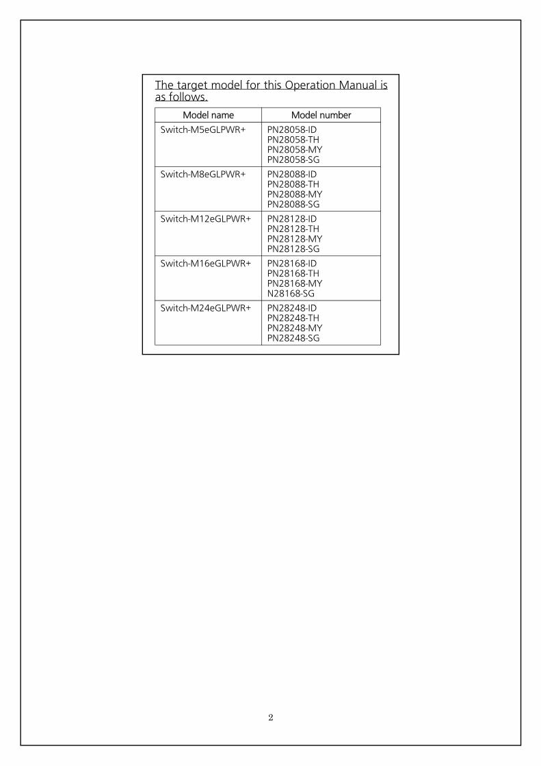
The target model for this Operation Manual is as follows.
Model name Model number
Switch-M5eGLPWR+ PN28058-IDPN28058-THPN28058-MYPN28058-SG
Switch-M8eGLPWR+ PN28088-IDPN28088-THPN28088-MYPN28088-SG
Switch-M12eGLPWR+ PN28128-IDPN28128-THPN28128-MYPN28128-SG
Switch-M16eGLPWR+ PN28168-IDPN28168-THPN28168-MYN28168-SG
Switch-M24eGLPWR+ PN28248-IDPN28248-THPN28248-MYPN28248-SG
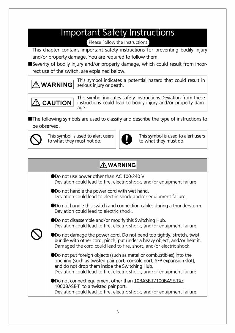
This chapter contains important safety instructions for preventing bodily injury
and/or property damage. You are required to follow them.
■Severity of bodily injury and/or property damage, which could result from incor-
rect use of the switch, are explained below.
This symbol indicates a potential hazard that could result in serious injury or death.
This symbol indicates safety instructions.Deviation from these instructions could lead to bodily injury and/or property dam- age.
■The following symbols are used to classify and describe the type of instructions to
be observed.
This symbol is used to alert users to what they must not do.
This symbol is used to alert users to what they must do.
●Do not use power other than AC 100-240 V.Deviation could lead to fire, electric shock, and/or equipment failure.
●Do not handle the power cord with wet hand.Deviation could lead to electric shock and/or equipment failure.
●Do not handle this switch and connection cables during a thunderstorm.Deviation could lead to electric shock.
●Do not disassemble and/or modify this Switching Hub.Deviation could lead to fire, electric shock, and/or equipment failure.
●Do not damage the power cord. Do not bend too tightly, stretch, twist, bundle with other cord, pinch, put under a heavy object, and/or heat it.Damaged the cord could lead to fire, short, and/or electric shock.
●Do not put foreign objects (such as metal or combustibles) into the opening (such as twisted pair port, console port, SFP expansion slot), and do not drop them inside the Switching Hub.Deviation could lead to fire, electric shock, and/or equipment failure.
●Do not connect equipment other than 10BASE-T/100BASE-TX/1000BASE-T to a twisted pair port.Deviation could lead to fire, electric shock, and/or equipment failure.
Important Safety InstructionsPlease Follow the Instructions
3
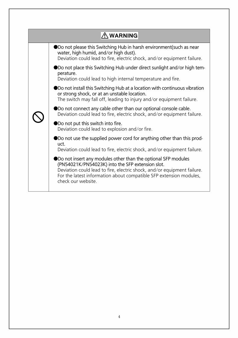
●Do not please this Switching Hub in harsh environment(such as near water, high humid, and/or high dust).Deviation could lead to fire, electric shock, and/or equipment failure.
●Do not place this Switching Hub under direct sunlight and/or high tem-perature.Deviation could lead to high internal temperature and fire.
●Do not install this Switching Hub at a location with continuous vibration or strong shock, or at an unstable location.The switch may fall off, leading to injury and/or equipment failure.
●Do not connect any cable other than our optional console cable.Deviation could lead to fire, electric shock, and/or equipment failure.
●Do not put this switch into fire.Deviation could lead to explosion and/or fire.
●Do not use the supplied power cord for anything other than this prod-uct.Deviation could lead to fire, electric shock, and/or equipment failure.
●Do not insert any modules other than the optional SFP modules (PN54021K/PN54023K) into the SFP extension slot.Deviation could lead to fire, electric shock, and/or equipment failure.For the latest information about compatible SFP extension modules, check our website.
4
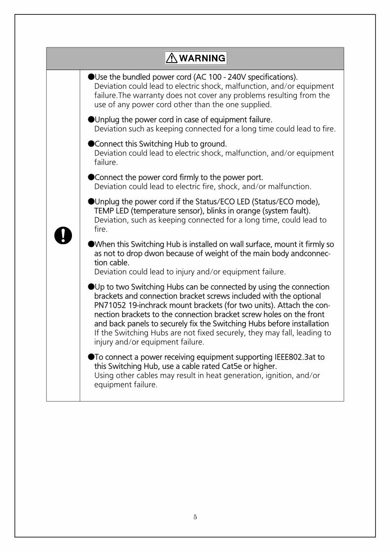
●Use the bundled power cord (AC 100 - 240V specifications).Deviation could lead to electric shock, malfunction, and/or equipment failure.The warranty does not cover any problems resulting from the use of any power cord other than the one supplied.
●Unplug the power cord in case of equipment failure.Deviation such as keeping connected for a long time could lead to fire.
●Connect this Switching Hub to ground.Deviation could lead to electric shock, malfunction, and/or equipment failure.
●Connect the power cord firmly to the power port.Deviation could lead to electric fire, shock, and/or malfunction.
●Unplug the power cord if the Status/ECO LED (Status/ECO mode), TEMP LED (temperature sensor), blinks in orange (system fault).Deviation, such as keeping connected for a long time, could lead to fire.
●When this Switching Hub is installed on wall surface, mount it firmly so as not to drop dwon because of weight of the main body andconnec-tion cable.Deviation could lead to injury and/or equipment failure.
●Up to two Switching Hubs can be connected by using the connection brackets and connection bracket screws included with the optional PN71052 19-inchrack mount brackets (for two units). Attach the con-nection brackets to the connection bracket screw holes on the front and back panels to securely fix the Switching Hubs before installationIf the Switching Hubs are not fixed securely, they may fall, leading to injury and/or equipment failure.
●To connect a power receiving equipment supporting IEEE802.3at to this Switching Hub, use a cable rated Cat5e or higher.Using other cables may result in heat generation, ignition, and/or equipment failure.
5
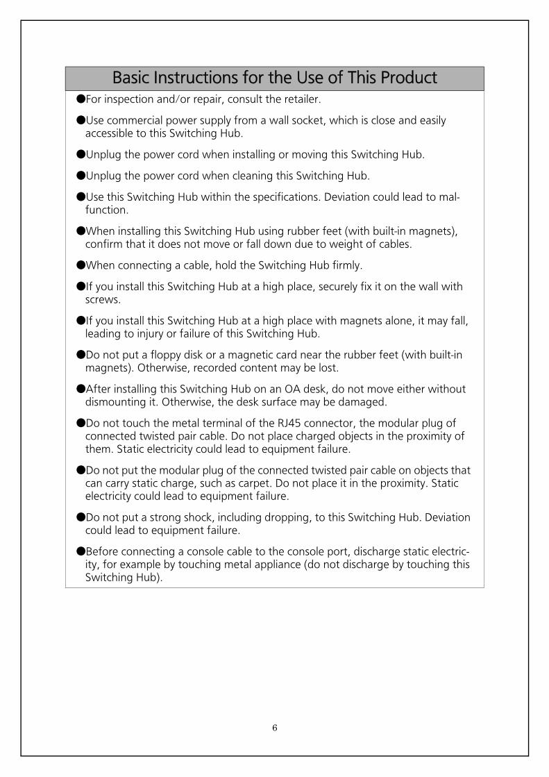
Basic Instructions for the Use of This Product●For inspection and/or repair, consult the retailer.
●Use commercial power supply from a wall socket, which is close and easily accessible to this Switching Hub.
●Unplug the power cord when installing or moving this Switching Hub.
●Unplug the power cord when cleaning this Switching Hub.
●Use this Switching Hub within the specifications. Deviation could lead to mal-function.
●When installing this Switching Hub using rubber feet (with built-in magnets), confirm that it does not move or fall down due to weight of cables.
●When connecting a cable, hold the Switching Hub firmly.
●If you install this Switching Hub at a high place, securely fix it on the wall with screws.
●If you install this Switching Hub at a high place with magnets alone, it may fall, leading to injury or failure of this Switching Hub.
●Do not put a floppy disk or a magnetic card near the rubber feet (with built-in magnets). Otherwise, recorded content may be lost.
●After installing this Switching Hub on an OA desk, do not move either without dismounting it. Otherwise, the desk surface may be damaged.
●Do not touch the metal terminal of the RJ45 connector, the modular plug of connected twisted pair cable. Do not place charged objects in the proximity of them. Static electricity could lead to equipment failure.
●Do not put the modular plug of the connected twisted pair cable on objects that can carry static charge, such as carpet. Do not place it in the proximity. Static electricity could lead to equipment failure.
●Do not put a strong shock, including dropping, to this Switching Hub. Deviation could lead to equipment failure.
●Before connecting a console cable to the console port, discharge static electric-ity, for example by touching metal appliance (do not discharge by touching this Switching Hub).
6
1. Panasonic will not be liable for any damage resulting from the operation not in
accordance with this operation manual, or loss of communications, which may or
may not be caused by failure and/or malfunction of this device.
2. The contents described in this document may be changed without prior notice.
3. For any questions, please contact your dealer.
* Brands and product names in this document are trademarks or registered trademarks
of their respective holders.
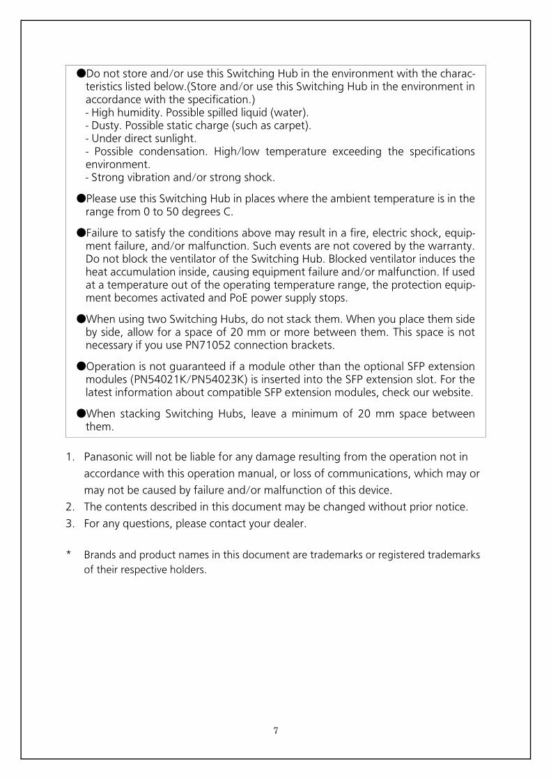
●Do not store and/or use this Switching Hub in the environment with the charac- teristics listed below.(Store and/or use this Switching Hub in the environment in accordance with the specification.) - High humidity. Possible spilled liquid (water). - Dusty. Possible static charge (such as carpet). - Under direct sunlight. - Possible condensation. High/low temperature exceeding the specifications environment. - Strong vibration and/or strong shock.
●Please use this Switching Hub in places where the ambient temperature is in the range from 0 to 50 degrees C.
●Failure to satisfy the conditions above may result in a fire, electric shock, equip- ment failure, and/or malfunction. Such events are not covered by the warranty. Do not block the ventilator of the Switching Hub. Blocked ventilator induces the heat accumulation inside, causing equipment failure and/or malfunction. If used at a temperature out of the operating temperature range, the protection equip- ment becomes activated and PoE power supply stops.
●When using two Switching Hubs, do not stack them. When you place them side by side, allow for a space of 20 mm or more between them. This space is not necessary if you use PN71052 connection brackets.
●Operation is not guaranteed if a module other than the optional SFP extension modules (PN54021K/PN54023K) is inserted into the SFP extension slot. For the latest information about compatible SFP extension modules, check our website.
●When stacking Switching Hubs, leave a minimum of 20 mm space between them.
7
Table of ContentsImportant Safety Instructions .......................................................................................................................... 3
● Basic Instructions for the Use of This Product .................................................. 6
1. Product Outline ........................................................................................ 10
2. Web Browser-based Control ..................................................................... 112.1. System Requirements ........................................................................... 112.2. Access to Web Control Function ........................................................... 122.3. Display of Switch Information ............................................................... 15
3. Switch Configuration ............................................................................... 173.1. Basic Config ......................................................................................... 17
3.1.1.Administration Configration ............................................................ 173.1.2.IP Config ......................................................................................... 183.1.3.SNMP Config .................................................................................. 193.1.4.Basic Trap Configuration ................................................................. 203.1.5.Advanced Trap Configuration .......................................................... 213.1.6.Basic port Configration .................................................................... 233.1.7.Extend Port Configration ................................................................. 253.1.8.Power Saving Port Configration ....................................................... 263.1.9.System Security ............................................................................... 273.1.10.Syslog Transmission Configration .................................................. 293.1.11.RADIUS Configuration ................................................................... 303.1.12.Telnet Access Limit ........................................................................ 313.1.13.ID/Password Change ..................................................................... 323.1.14.MAC Learning ............................................................................... 333.1.15.FDB Manual Setting ...................................................................... 343.1.16.FDB Table ...................................................................................... 353.1.17.Time Configration ......................................................................... 363.1.18.Static ARP Table ............................................................................ 373.1.19.ARP Table ..................................................................................... 383.1.20.LLDP Port Config ........................................................................... 393.1.21.LLDP Neighbor Table ..................................................................... 41
3.2. Advanced Switch Configuration ........................................................... 423.2.1.VLAN Management ........................................................................ 42
3.2.1.a. VLAN Modification ............................................................... 433.2.2.VLAN Creation ................................................................................ 443.2.3.VLAN Port Config ............................................................................ 453.2.4.QoS Config ..................................................................................... 463.2.5.Egress Rate Limiting Config ............................................................. 473.2.6.Diffserv Config ................................................................................ 483.2.7.Link Aggregation Config ................................................................. 49
3.2.7.a. Link Aggregation Modification ............................................. 50
8
3.2.8.Storm Control Config ...................................................................... 513.2.9.802.1X Port Based Access Control Configuration ............................. 523.2.10.Port Monitoring Configration ........................................................ 543.2.11.STP Global Config ......................................................................... 563.2.12.Parameter Config .......................................................................... 573.2.13.Basic Port Config ........................................................................... 593.2.14.Advanced Port Config ................................................................... 613.2.15.Designated Topology Info ............................................................. 633.2.16.PoE Port Config ............................................................................. 643.2.17.PoE Global Configration ................................................................ 663.2.18.PoE Schedule Port List Info ............................................................ 673.2.19.PoE Schedule Port List Config ........................................................ 683.2.20.PoE Schedule Info ......................................................................... 693.2.21.PoE Schedule Config ..................................................................... 713.2.22.Date List Info ................................................................................. 753.2.23.Date List Config ............................................................................ 763.2.24.PoE Display Schedule By Port ......................................................... 773.2.25.Loop Detection Config .................................................................. 783.2.26.Loop History Info ........................................................................... 793.2.27.RRP Domain Management ............................................................ 803.2.28.DMI (DDM) Config ........................................................................ 823.2.29.IGMP Snooping Configuration ....................................................... 833.2.30.VLAN Filter Config ......................................................................... 843.2.31.Router Port List ............................................................................. 85
3.3. System Tools ........................................................................................ 863.3.1.Software Update ............................................................................. 863.3.2.Reboot ............................................................................................ 873.3.3.Save Current Config ........................................................................ 883.3.4.Statistics .......................................................................................... 893.3.5.System log ...................................................................................... 923.3.6.Config File Transfer ......................................................................... 943.3.7.Ping Execution ................................................................................ 953.3.8.Watchdog Timer ............................................................................. 96
4. Specifications ........................................................................................... 97
5. Easy IP Address Setup Function ................................................................ 98
6. Troubleshooting ....................................................................................... 99
7. After-sales Service .................................................................................. 100
9

10
1. Product OutlineThank you for purchasing the Switching Hub(hereinafter called "this switch"). This manual provides information required to use the Web control function of this switch.
11
2. Web Browser-based ControlThe web-browser-based administration function (hereinafter called the Web con- trol function) allows you to easily perform administration task, such as configura- tion and monitoring, from a web browser, Microsoft Internet Explorer.The Web control function allows you to configure and monitor this switch over the network via the user interface of your Web browser. You can also control this switch from a remote location as if it is at your fingertips because statuses can be displayed.
2.1. System RequirementsYou need to configure the network settings before using the Web control function of this switch.
1. Configuring the System IP Address Using the console, configure the IP address of this switch. Select "Basic Switch Configuration..." > "System IP Configuration" > "Set IP Address" to configure the IP address. Then, select "Set Subnet Mask" to config-ure the subnet mask. If required, select "Set Default Gateway" to configure the default gateway address.
2. Enabling the Web Control Function Enable the Web control function of this switch. From the main menu, select "Basic Switch Configuration..." > "System Security Configuration" > "Web Server Status" and the command prompt changes to "Enable or Disable web server(E/D)." Enter "e" to enable the Web control func-tion. "Disable" is the factory default setting.
The terminal must be connected over a network or directly to this switch.The terminal to access the Switching Hub must have a web browser (Microsoft Internet Explorer 11 (recommend)) and Java RE (Ver. 1.4 or above) installed.Further, the terminal must be connected to the Switching Hub directly or via net-work.
Note: The active window may not be correctly displayed if you use a proxy. Direct access without a proxy is recommended.
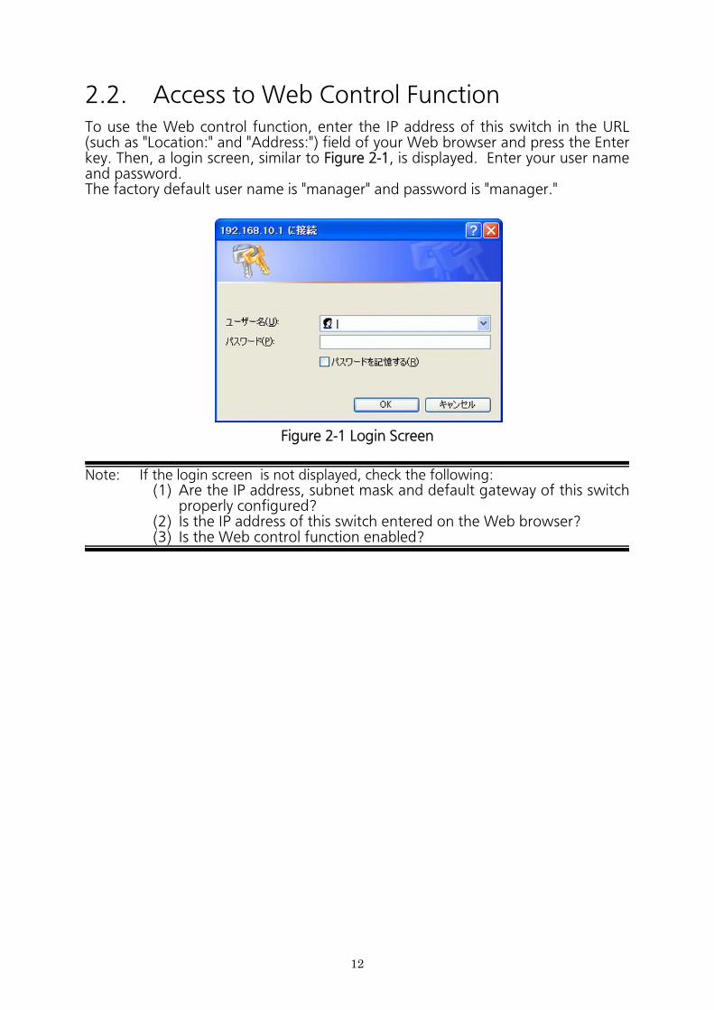
2.2. Access to Web Control FunctionTo use the Web control function, enter the IP address of this switch in the URL (such as "Location:" and "Address:") field of your Web browser and press the Enter key. Then, a login screen, similar to Figure 2-1, is displayed. Enter your user name and password.The factory default user name is "manager" and password is "manager."
Figure 2-1 Login Screen
Note: If the login screen is not displayed, check the following:(1) Are the IP address, subnet mask and default gateway of this switch
properly configured?(2) Is the IP address of this switch entered on the Web browser?(3) Is the Web control function enabled?
12
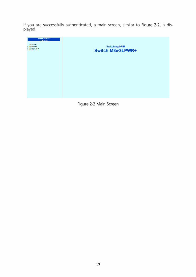
Figure 2-2 Main Screen
13

The left side of the screen shows a list of actions available to you on this screen.
(1) General Info Displays a list of basic information of this switch.
(2) Basic Config Configure the basic settings such as IP address and port settings.
(3) Advanced Config Configure the advanced settings such as VLAN, QoS, and IGMP snooping.
(4) System Tools Use these management tools to update the firmware and browse system logs.
To conduct operation management, it is recommended to conduct the "Basic Con- fig" first, before configuring other advanced settings.
14
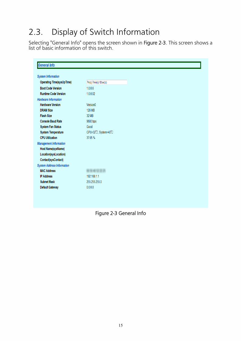
2.3. Display of Switch InformationSelecting "General Info" opens the screen shown in Figure 2-3. This screen shows a list of basic information of this switch.
Figure 2-3 General Info
15
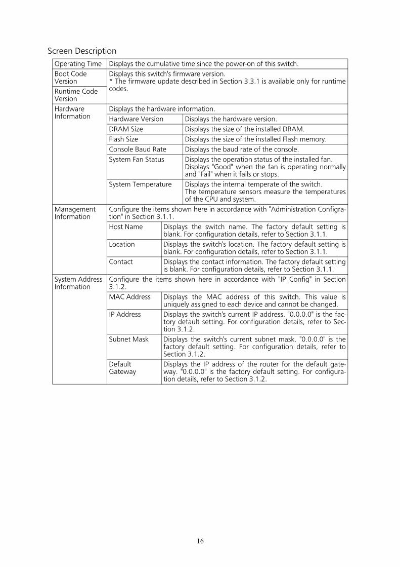
Screen Description
Operating Time Displays the cumulative time since the power-on of this switch.
Boot Code Version
Displays this switch's firmware version.* The firmware update described in Section 3.3.1 is available only for runtime codes.Runtime Code
Version
HardwareInformation
Displays the hardware information.
Hardware Version Displays the hardware version.
DRAM Size Displays the size of the installed DRAM.
Flash Size Displays the size of the installed Flash memory.
Console Baud Rate Displays the baud rate of the console.
System Fan Status Displays the operation status of the installed fan.Displays "Good" when the fan is operating normally and "Fail" when it fails or stops.
System Temperature Displays the internal temperate of the switch.The temperature sensors measure the temperatures of the CPU and system.
ManagementInformation
Configure the items shown here in accordance with "Administration Configra- tion" in Section 3.1.1.
Host Name Displays the switch name. The factory default setting is blank. For configuration details, refer to Section 3.1.1.
Location Displays the switch's location. The factory default setting is blank. For configuration details, refer to Section 3.1.1.
Contact Displays the contact information. The factory default setting is blank. For configuration details, refer to Section 3.1.1.
System AddressInformation
Configure the items shown here in accordance with "IP Config" in Section 3.1.2.
MAC Address Displays the MAC address of this switch. This value is uniquely assigned to each device and cannot be changed.
IP Address Displays the switch's current IP address. "0.0.0.0" is the fac- tory default setting. For configuration details, refer to Sec- tion 3.1.2.
Subnet Mask Displays the switch's current subnet mask. "0.0.0.0" is the factory default setting. For configuration details, refer to Section 3.1.2.
Default Gateway
Displays the IP address of the router for the default gate- way. "0.0.0.0" is the factory default setting. For configura- tion details, refer to Section 3.1.2.
16
17
3. Switch ConfigurationAfter completing configuration, you must save the configuration information in accordance with Section 3.3.3. Unless the configuration information is saved, the settings configured so far will not be reflected after restart.
3.1. Basic Config
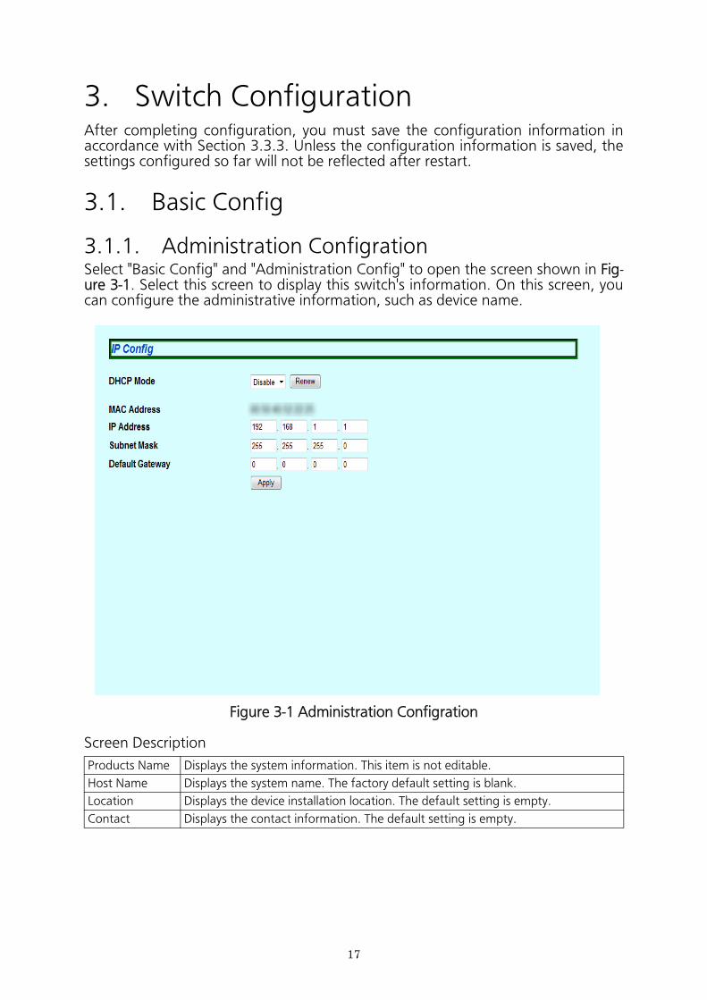
3.1.1. Administration ConfigrationSelect "Basic Config" and "Administration Config" to open the screen shown in Fig- ure 3-1. Select this screen to display this switch's information. On this screen, you can configure the administrative information, such as device name.
Figure 3-1 Administration Configration
Screen Description
Products Name Displays the system information. This item is not editable.
Host Name Displays the system name. The factory default setting is blank.
Location Displays the device installation location. The default setting is empty.
Contact Displays the contact information. The default setting is empty.
18
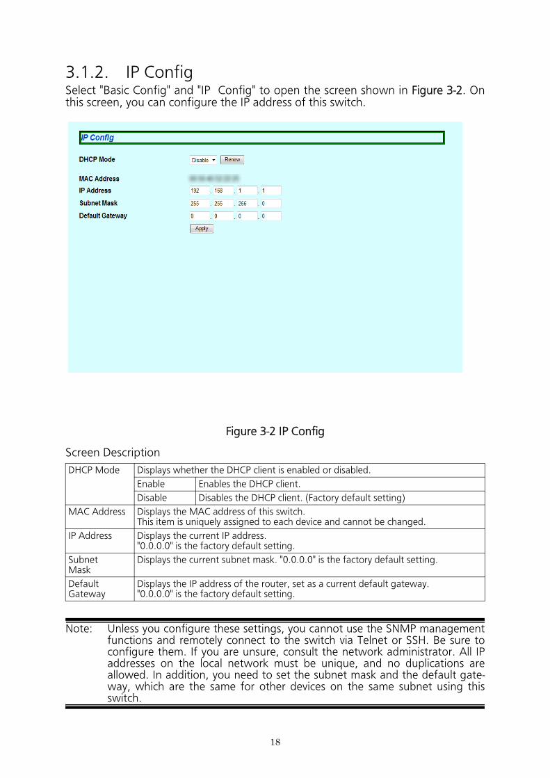
3.1.2. IP ConfigSelect "Basic Config" and "IP Config" to open the screen shown in Figure 3-2. On this screen, you can configure the IP address of this switch.
Figure 3-2 IP Config
Screen Description
Note: Unless you configure these settings, you cannot use the SNMP management functions and remotely connect to the switch via Telnet or SSH. Be sure to configure them. If you are unsure, consult the network administrator. All IP addresses on the local network must be unique, and no duplications are allowed. In addition, you need to set the subnet mask and the default gate- way, which are the same for other devices on the same subnet using this switch.
DHCP Mode Displays whether the DHCP client is enabled or disabled.
Enable Enables the DHCP client.
Disable Disables the DHCP client. (Factory default setting)
MAC Address Displays the MAC address of this switch.This item is uniquely assigned to each device and cannot be changed.
IP Address Displays the current IP address."0.0.0.0" is the factory default setting.
SubnetMask
Displays the current subnet mask. "0.0.0.0" is the factory default setting.
DefaultGateway
Displays the IP address of the router, set as a current default gateway."0.0.0.0" is the factory default setting.
19
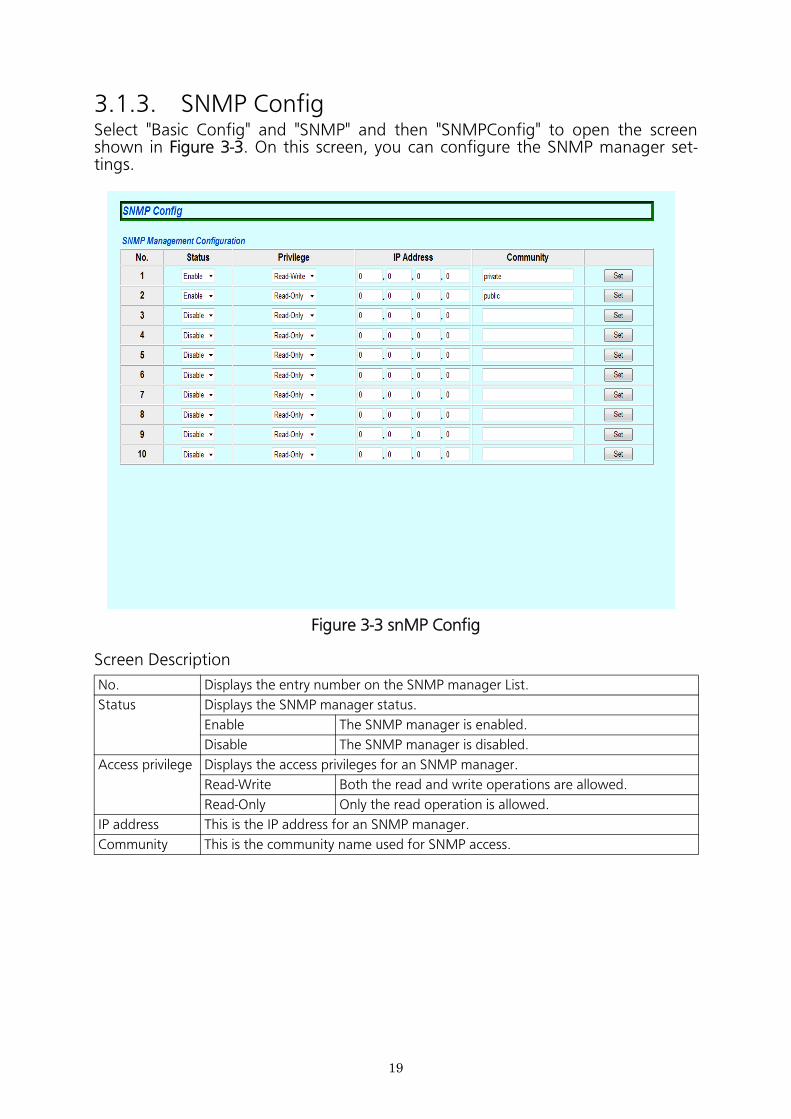
3.1.3. SNMP ConfigSelect "Basic Config" and "SNMP" and then "SNMPConfig" to open the screen shown in Figure 3-3. On this screen, you can configure the SNMP manager set- tings.
Figure 3-3 snMP Config
Screen Description
No. Displays the entry number on the SNMP manager List.
Status Displays the SNMP manager status.
Enable The SNMP manager is enabled.
Disable The SNMP manager is disabled.
Access privilege Displays the access privileges for an SNMP manager.
Read-Write Both the read and write operations are allowed.
Read-Only Only the read operation is allowed.
IP address This is the IP address for an SNMP manager.
Community This is the community name used for SNMP access.
20
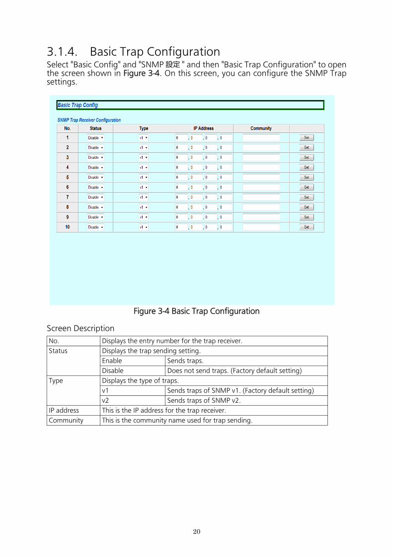
3.1.4. Basic Trap ConfigurationSelect "Basic Config" and "SNMP 設定 " and then "Basic Trap Configuration" to open the screen shown in Figure 3-4. On this screen, you can configure the SNMP Trap settings.
Figure 3-4 Basic Trap Configuration
Screen Description
No. Displays the entry number for the trap receiver.
Status Displays the trap sending setting.
Enable Sends traps.
Disable Does not send traps. (Factory default setting)
Type Displays the type of traps.
v1 Sends traps of SNMP v1. (Factory default setting)
v2 Sends traps of SNMP v2.
IP address This is the IP address for the trap receiver.
Community This is the community name used for trap sending.
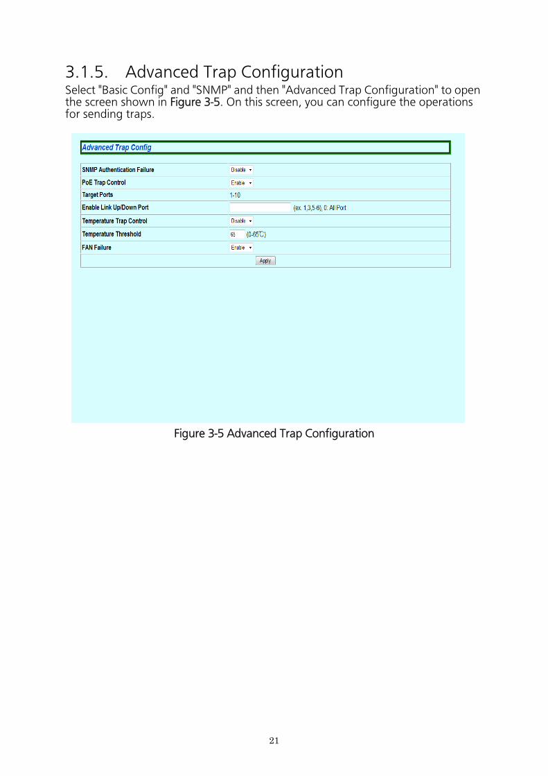
3.1.5. Advanced Trap ConfigurationSelect "Basic Config" and "SNMP" and then "Advanced Trap Configuration" to open the screen shown in Figure 3-5. On this screen, you can configure the operations for sending traps.
Figure 3-5 Advanced Trap Configuration
21
Screen Description
SNMPAuthentica-tion Failuer
Displays the trap sending setting for an SNMP authentication failure.
Enable Enables the trap sending.
Disable Disables the trap sending. (Factory default setting)
PoE Trap Control Displays the PoE trap control settings.
Enable Enables the trap sending.
Disable Disables the trap sending. (Factory default setting)
Target Port Displays a target port that has been configured.
Enable Link UP/Down Port
Configure a port to which the trap is sent when its link status changes.
Temperature Trap Control
Displays the temperature trap control settings.
Enable Enables the trap sending.
Disable Disables the trap sending. (Factory default setting)
Temperature Threshold
Displays the threshold temperature value to send the trap.
Fan Failure Displays the fan trap control settings.
Enabled Enables the trap sending. (Factory default setting)
Disabled Disables the trap sending.
22
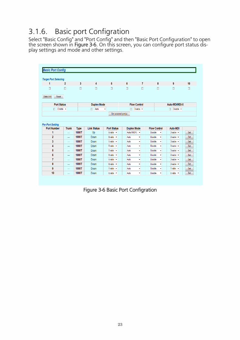
3.1.6. Basic port ConfigrationSelect "Basic Config" and "Port Config" and then "Basic Port Configuration" to open the screen shown in Figure 3-6. On this screen, you can configure port status dis-play settings and mode and other settings.
Figure 3-6 Basic Port Configration
23
Screen Description
Port Number Displays the port number.
\Trunk Displays the group number for a trunked port.
Type Displays the port type.
100TX The port type is 10/100BASE-TX.
1000T The port type is 1000BASE-T.
1000X The port type is SFP port.
Port Status Displays the current port status. For all ports, "Enable" is the factory default set- ting.
Enable The port is available.
Disable The port is not available.
Link Status Displays the current link status.
Up A link has been established successfully.
Down A link has not been established.
Duplex Mode Displays the communication speed and full-duplex/half-duplex settings.For all ports, "Auto" is the factory default setting.
Auto Auto negotiation mode
100M/Full 100 Mbps full-duplex
100M/Half 100 Mbps half-duplex
10M/Full 10 Mbps full-duplex
10M/Half 10 Mbps half-duplex
Flow Control Displays the flow control settings.For all ports, "Disable" is the factory default setting.
Enable The flow control is enabled.
Disable The flow control is disabled.
Auto-MDI Displays the Auto MDI/MDI-X function settings. Ports 1 to -20 are set to "Dis- able," and Ports 21 to -24 are set to "Enable" at factory default setting.
Enable The Auto-MDI/MDI-X function is enabled.
Disable The Auto-MDI/MDI-X function is disabled.
24
25
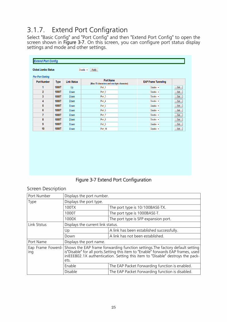
3.1.7. Extend Port ConfigrationSelect "Basic Config" and "Port Config" and then "Extend Port Config" to open the screen shown in Figure 3-7. On this screen, you can configure port status display settings and mode and other settings.
Figure 3-7 Extend Port Configuration
Screen Description
Port Number Displays the port number.
Type Displays the port type.
100TX The port type is 10/100BASE-TX.
1000T The port type is 1000BASE-T.
1000X The port type is SFP expansion port.
Link Ststus Displays the current link status.
Up A link has been established successfully.
Down A link has not been established.
Port Name Displays the port name.
Eap Frame Fowerd- ing
Shows the EAP frame forwarding function settings.The factory default setting is"Disable" for all ports.Setting this item to "Enable" forwards EAP frames, used inIEEE802.1X authentication. Setting this item to "Disable" destroys the pack- ets.
Enable The EAP Packet Forwarding function is enabled.
Disable The EAP Packet Forwarding function is disabled.
26
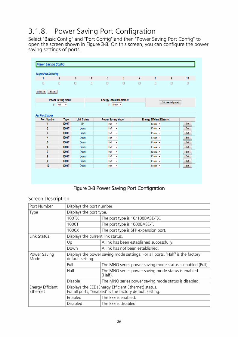
3.1.8. Power Saving Port ConfigrationSelect "Basic Config" and "Port Config" and then "Power Saving Port Config" to open the screen shown in Figure 3-8. On this screen, you can configure the power saving settings of ports.
Figure 3-8 Power Saving Port Configration
Screen Description
Port Number Displays the port number.
Type Displays the port type.
100TX The port type is 10/100BASE-TX.
1000T The port type is 1000BASE-T.
1000X The port type is SFP expansion port.
Link Status Displays the current link status.
Up A link has been established successfully.
Down A link has not been established.
Power Saving Mode
Displays the power saving mode settings. For all ports, "Half" is the factory default setting.
Full The MNO series power saving mode status is enabled (Full).
Half The MNO series power saving mode status is enabled (Half).
Disable The MNO series power saving mode status is disabled.
Energy Efficient Ethernet
Displays the EEE (Energy Efficient Ethernet) status.For all ports, "Enabled" is the factory default setting.
Enabled The EEE is enabled.
Disabled The EEE is disabled.
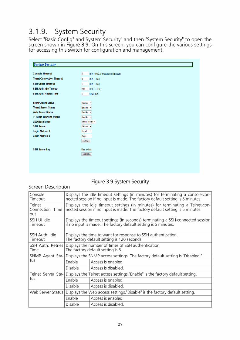
3.1.9. System SecuritySelect "Basic Config" and System Security" and then "System Security" to open the screen shown in Figure 3-9. On this screen, you can configure the various settings for accessing this switch for configuration and management.
Figure 3-9 System SecurityScreen Description
ConsoleTimeout
Displays the idle timeout settings (in minutes) for terminating a console-con- nected session if no input is made. The factory default setting is 5 minutes.
TelnetConnection Time- out
Displays the idle timeout settings (in minutes) for terminating a Telnet-con- nected session if no input is made. The factory default setting is 5 minutes.
SSH UI Idle Timeout
Displays the timeout settings (in seconds) terminating a SSH-connected session if no input is made. The factory default setting is 5 minutes.
SSH Auth. Idle Timeout
Displays the time to want for response to SSH authentication. The factory default setting is 120 seconds.
SSH Auth. Retries Time
Displays the number of times of SSH authentication.The factory default setting is 5.
SNMP Agent Sta- tus
Displays the SNMP access settings. The factory default setting is "Disabled."
Enable Access is enabled.
Disable Access is disabled.
Telnet Server Sta- tus
Displays the Telnet access settings."Enable" is the factory default setting.
Enable Access is enabled.
Disable Access is disabled.
Web Server Status Displays the Web access settings."Disable" is the factory default setting.
Enable Access is enabled.
Disable Access is disabled.
27
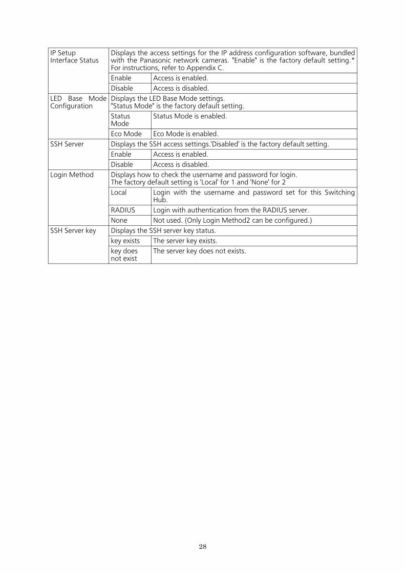
IP SetupInterface Status
Displays the access settings for the IP address configuration software, bundled with the Panasonic network cameras. "Enable" is the factory default setting.* For instructions, refer to Appendix C.
Enable Access is enabled.
Disable Access is disabled.
LED Base Mode Configuration
Displays the LED Base Mode settings."Status Mode" is the factory default setting.
Status Mode
Status Mode is enabled.
Eco Mode Eco Mode is enabled.
SSH Server Displays the SSH access settings.'Disabled' is the factory default setting.
Enable Access is enabled.
Disable Access is disabled.
Login Method Displays how to check the username and password for login.The factory default setting is 'Local' for 1 and 'None' for 2
Local Login with the username and password set for this Switching Hub.
RADIUS Login with authentication from the RADIUS server.
None Not used. (Only Login Method2 can be configured.)
SSH Server key Displays the SSH server key status.
key exists The server key exists.
key does not exist
The server key does not exists.
28
29
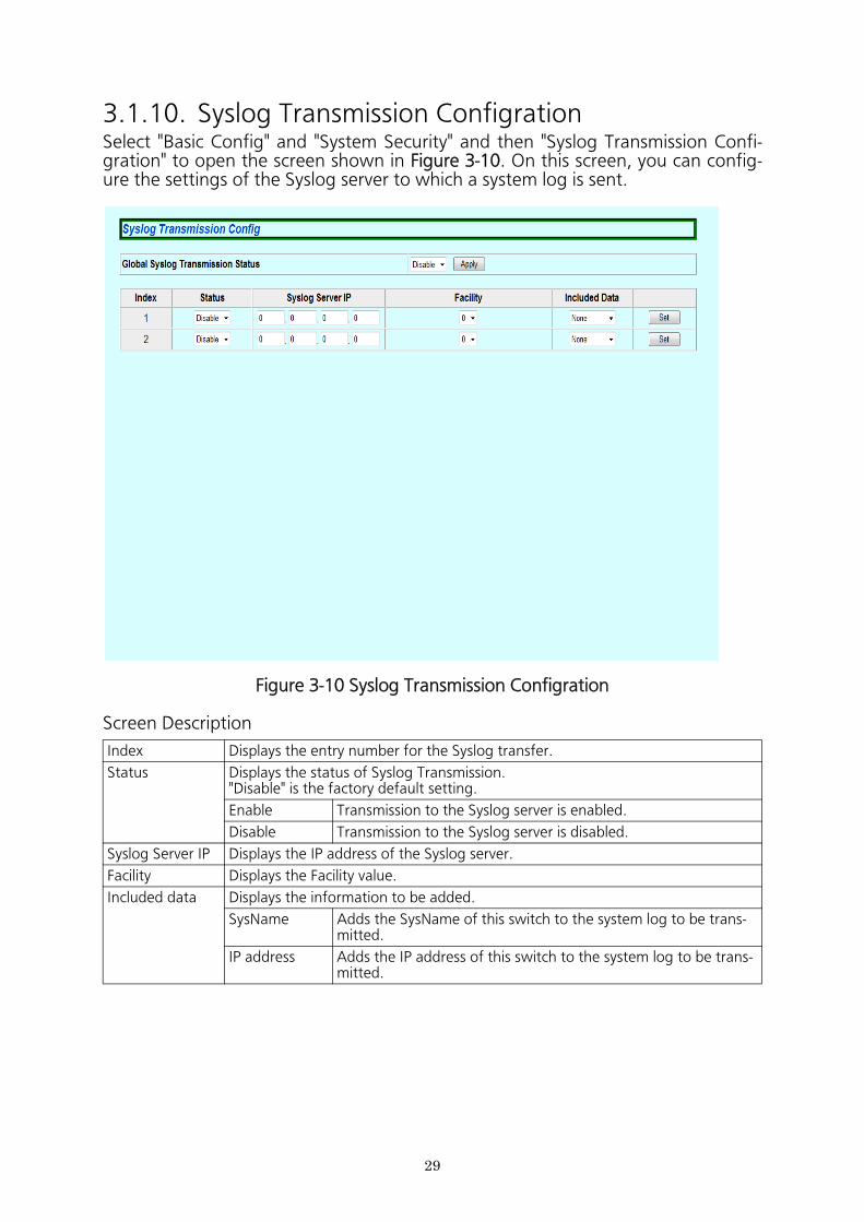
3.1.10. Syslog Transmission ConfigrationSelect "Basic Config" and "System Security" and then "Syslog Transmission Confi- gration" to open the screen shown in Figure 3-10. On this screen, you can config- ure the settings of the Syslog server to which a system log is sent.
Figure 3-10 Syslog Transmission Configration
Screen Description
Index Displays the entry number for the Syslog transfer.
Status Displays the status of Syslog Transmission."Disable" is the factory default setting.
Enable Transmission to the Syslog server is enabled.
Disable Transmission to the Syslog server is disabled.
Syslog Server IP Displays the IP address of the Syslog server.
Facility Displays the Facility value.
Included data Displays the information to be added.
SysName Adds the SysName of this switch to the system log to be trans-mitted.
IP address Adds the IP address of this switch to the system log to be trans-mitted.
30
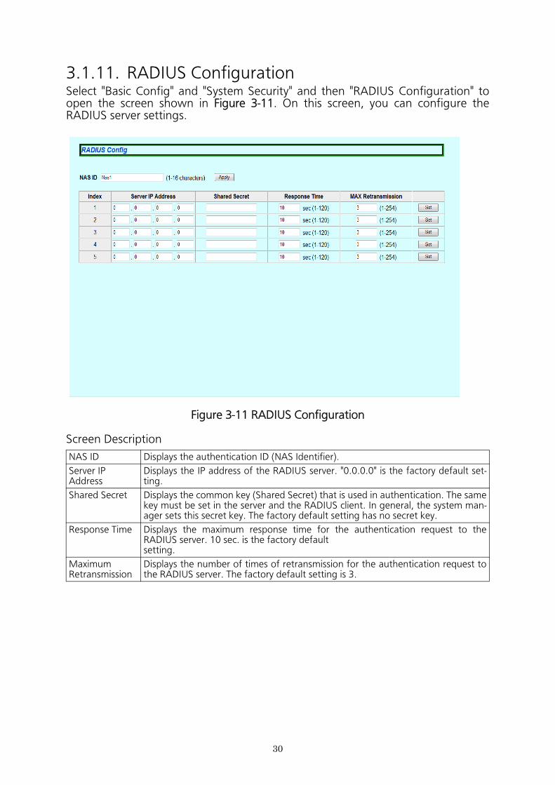
3.1.11. RADIUS ConfigurationSelect "Basic Config" and "System Security" and then "RADIUS Configuration" to open the screen shown in Figure 3-11. On this screen, you can configure the RADIUS server settings.
Figure 3-11 RADIUS Configuration
Screen Description
NAS ID Displays the authentication ID (NAS Identifier).
Server IP Address
Displays the IP address of the RADIUS server. "0.0.0.0" is the factory default set- ting.
Shared Secret Displays the common key (Shared Secret) that is used in authentication. The same key must be set in the server and the RADIUS client. In general, the system man- ager sets this secret key. The factory default setting has no secret key.
Response Time Displays the maximum response time for the authentication request to the RADIUS server. 10 sec. is the factory defaultsetting.
Maximum Retransmission
Displays the number of times of retransmission for the authentication request to the RADIUS server. The factory default setting is 3.
31
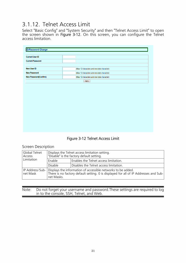
3.1.12. Telnet Access LimitSelect "Basic Config" and "System Security" and then "Telnet Access Limit" to open the screen shown in Figure 3-12. On this screen, you can configure the Telnet access limitation.
Figure 3-12 Telnet Access Limit
Screen Description
Note: Do not forget your username and password.These settings are required to log in to the console, SSH, Telnet, and Web.
Global Telnet Access Limitation
Displays the Telnet access limitation setting."Disable" is the factory default setting.
Enable Enables the Telnet access limitation.
Disable Disables the Telnet access limitation.
IP Address/Sub-net Mask
Displays the information of accessible networks to be added.There is no factory default setting. 0 is displayed for all of IP Addresses and Sub- net Masks.
32
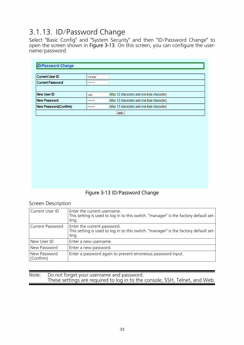
3.1.13. ID/Password ChangeSelect "Basic Config" and "System Security" and then "ID/Password Change" to open the screen shown in Figure 3-13. On this screen, you can configure the user- name/password.
Figure 3-13 ID/Password Change
Screen Description
Note: Do not forget your username and password. These settings are required to log in to the console, SSH, Telnet, and Web.
Current User ID Enter the current username.This setting is used to log in to this switch. "manager" is the factory default set- ting.
Current Password Enter the current password.This setting is used to log in to this switch. "manager" is the factory default set- ting.
New User ID Enter a new username.
New Password Enter a new password.
New Password (Confirm)
Enter a password again to prevent erroneous password input.
33
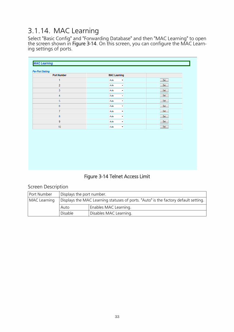
3.1.14. MAC LearningSelect "Basic Config" and "Forwarding Database" and then "MAC Learning" to open the screen shown in Figure 3-14. On this screen, you can configure the MAC Learn- ing settings of ports.
Figure 3-14 Telnet Access Limit
Screen Description
Port Number Displays the port number.
MAC Learning Displays the MAC Learning statuses of ports. "Auto" is the factory default setting.
Auto Enables MAC Learning.
Disable Disables MAC Learning.
34
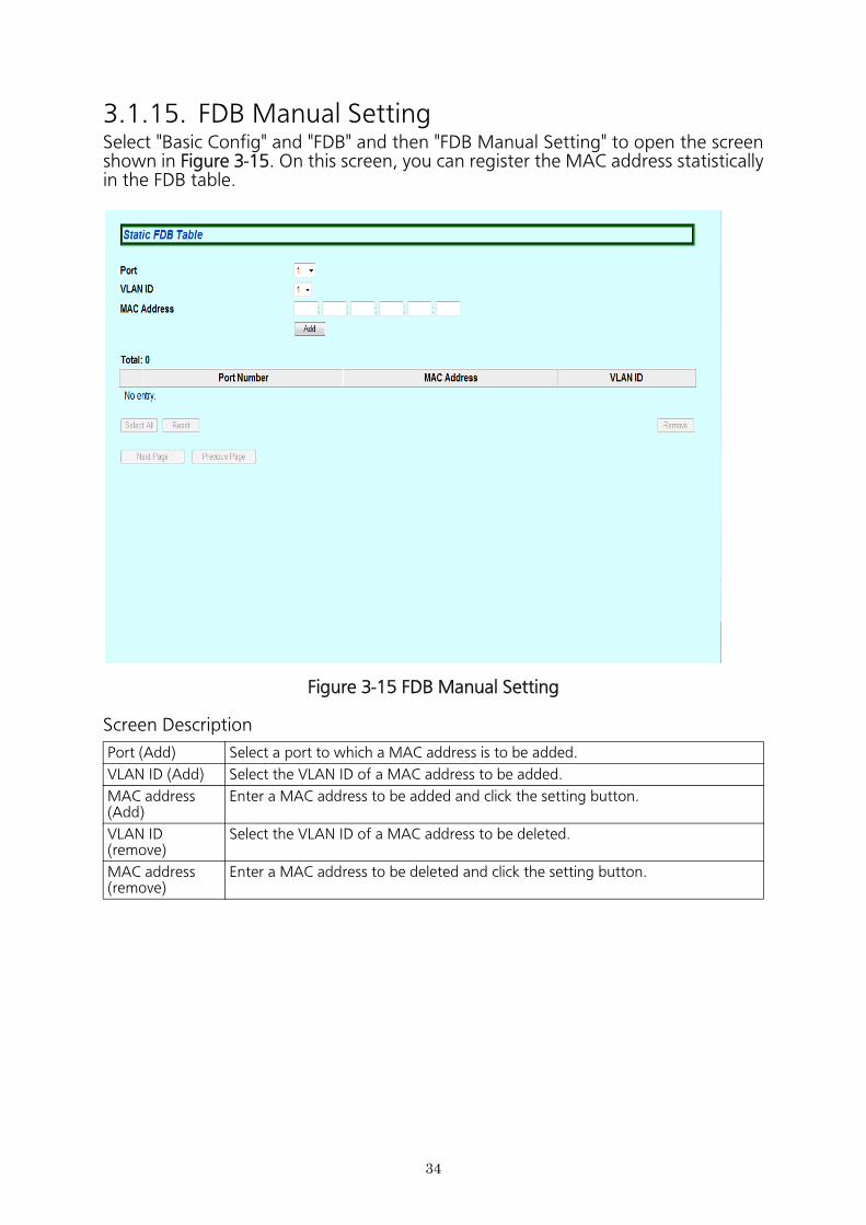
3.1.15. FDB Manual SettingSelect "Basic Config" and "FDB" and then "FDB Manual Setting" to open the screen shown in Figure 3-15. On this screen, you can register the MAC address statistically in the FDB table.
Figure 3-15 FDB Manual Setting
Screen Description
Port (Add) Select a port to which a MAC address is to be added.
VLAN ID (Add) Select the VLAN ID of a MAC address to be added.
MAC address(Add)
Enter a MAC address to be added and click the setting button.
VLAN ID (remove)
Select the VLAN ID of a MAC address to be deleted.
MAC address(remove)
Enter a MAC address to be deleted and click the setting button.
35
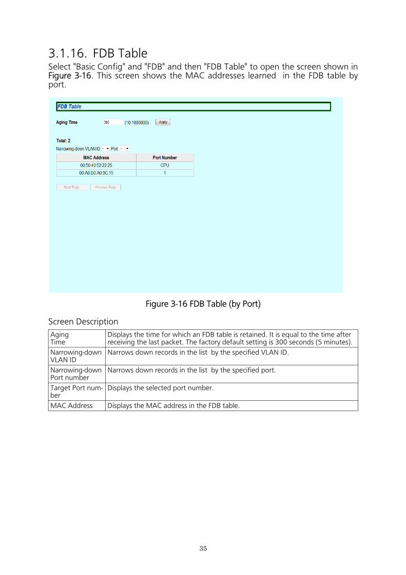
3.1.16. FDB TableSelect "Basic Config" and "FDB" and then "FDB Table" to open the screen shown in Figure 3-16. This screen shows the MAC addresses learned in the FDB table by port.
Figure 3-16 FDB Table (by Port)
Screen Description
Aging Time
Displays the time for which an FDB table is retained. It is equal to the time after receiving the last packet. The factory default setting is 300 seconds (5 minutes).
Narrowing-down VLAN ID
Narrows down records in the list by the specified VLAN ID.
Narrowing-down Port number
Narrows down records in the list by the specified port.
Target Port num-ber
Displays the selected port number.
MAC Address Displays the MAC address in the FDB table.
36
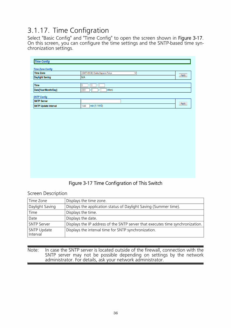
3.1.17. Time ConfigrationSelect "Basic Config" and "Time Config" to open the screen shown in Figure 3-17. On this screen, you can configure the time settings and the SNTP-based time syn- chronization settings.
Figure 3-17 Time Configration of This Switch
Screen Description
Note: In case the SNTP server is located outside of the firewall, connection with the SNTP server may not be possible depending on settings by the network administrator. For details, ask your network administrator.
Time Zone Displays the time zone.
Daylight Saving Displays the application status of Daylight Saving (Summer time).
Time Displays the time.
Date Displays the date.
SNTP Server Displays the IP address of the SNTP server that executes time synchronization.
SNTP Update Interval
Displays the interval time for SNTP synchronization.
37
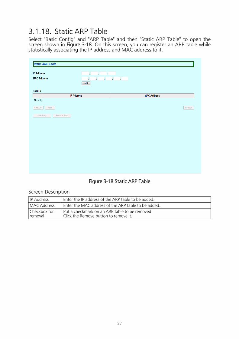
3.1.18. Static ARP TableSelect "Basic Config" and "ARP Table" and then "Static ARP Table" to open the screen shown in Figure 3-18. On this screen, you can register an ARP table while statistically associating the IP address and MAC address to it.
Figure 3-18 Static ARP Table
Screen Description
IP Address Enter the IP address of the ARP table to be added.
MAC Address Enter the MAC address of the ARP table to be added.
Checkbox for removal
Put a checkmark on an ARP table to be removed.Click the Remove button to remove it.
38
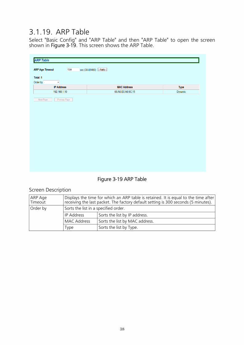
3.1.19. ARP TableSelect "Basic Config" and "ARP Table" and then "ARP Table" to open the screen shown in Figure 3-19. This screen shows the ARP Table.
Figure 3-19 ARP Table
Screen Description
ARP AgeTimeout
Displays the time for which an ARP table is retained. It is equal to the time after receiving the last packet. The factory default setting is 300 seconds (5 minutes).
Order by Sorts the list in a specified order.
IP Address Sorts the list by IP address.
MAC Address Sorts the list by MAC address.
Type Sorts the list by Type.
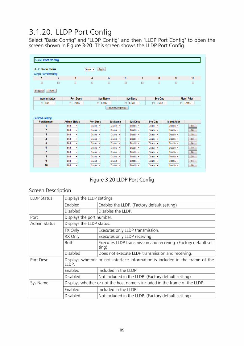
3.1.20. LLDP Port ConfigSelect "Basic Config" and "LLDP Config" and then "LLDP Port Config" to open the screen shown in Figure 3-20. This screen shows the LLDP Port Config.
Figure 3-20 LLDP Port Config
Screen Description
LLDP Status Displays the LLDP settings.
Enabled Enables the LLDP. (Factory default setting)
Disabled Disables the LLDP.
Port Displays the port number.
Admin Status Displays the LLDP status.
TX Only Executes only LLDP transmission.
RX Only Executes only LLDP receiving.
Both Executes LLDP transmission and receiving. (Factory default set- ting)
Disabled Does not execute LLDP transmission and receiving.
Port Desc Displays whether or not interface information is included in the frame of the LLDP.
Enabled Included in the LLDP.
Disabled Not included in the LLDP. (Factory default setting)
Sys Name Displays whether or not the host name is included in the frame of the LLDP.
Enabled Included in the LLDP.
Disabled Not included in the LLDP. (Factory default setting)
39

Sys Desc Displays whether or not system overview information is included in the frame of the LLDP.
Enabled Included in the LLDP.
Disabled Not included in the LLDP. (Factory default setting)
Sys Cap Displays whether or not system capability information is included in the frame of the LLDP.
Enabled Included in the LLDP.
Disabled Not included in the LLDP. (Factory default setting)
Mgmt Addr Displays whether or not the system IP address is included in the frame of the LLDP.
Enabled Included in the LLDP.
Disabled Not included in the LLDP. (Factory default setting)
40
41
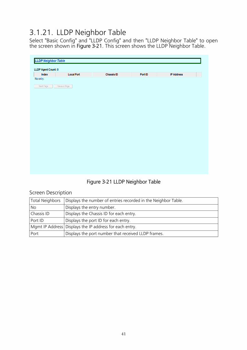
3.1.21. LLDP Neighbor TableSelect "Basic Config" and "LLDP Config" and then "LLDP Neighbor Table" to open the screen shown in Figure 3-21. This screen shows the LLDP Neighbor Table.
Figure 3-21 LLDP Neighbor Table
Screen Description
Total Neighbors Displays the number of entries recorded in the Neighbor Table.
No Displays the entry number.
Chassis ID Displays the Chassis ID for each entry.
Port ID Displays the port ID for each entry.
Mgmt IP Address Displays the IP address for each entry.
Port Displays the port number that received LLDP frames.
42
3.2. Advanced Switch Configuration
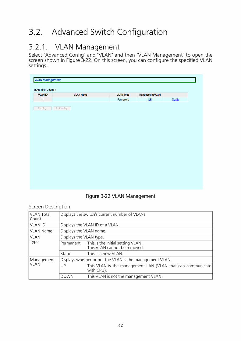
3.2.1. VLAN ManagementSelect "Advanced Config" and "VLAN" and then "VLAN Management" to open the screen shown in Figure 3-22. On this screen, you can configure the specified VLAN settings.
Figure 3-22 VLAN Management
Screen Description
VLAN Total Count
Displays the switch's current number of VLANs.
VLAN ID Displays the VLAN ID of a VLAN.
VLAN Name Displays the VLAN name.
VLANType
Displays the VLAN type.
Permanent This is the initial setting VLAN.This VLAN cannot be removed.
Static This is a new VLAN.
Management VLAN
Displays whether or not the VLAN is the management VLAN.
UP This VLAN is the management LAN (VLAN that can communicate with CPU).
DOWN This VLAN is not the management VLAN.
43
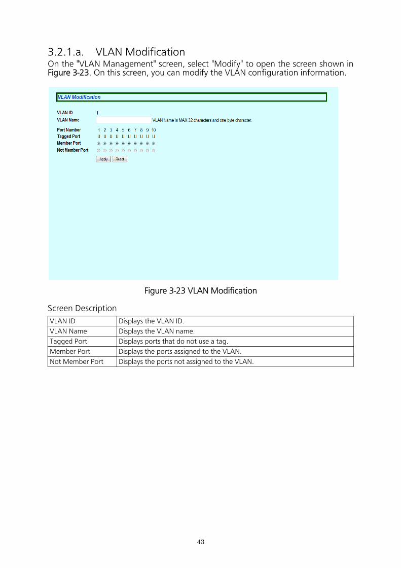
3.2.1.a. VLAN ModificationOn the "VLAN Management" screen, select "Modify" to open the screen shown in Figure 3-23. On this screen, you can modify the VLAN configuration information.
Figure 3-23 VLAN Modification
Screen Description
VLAN ID Displays the VLAN ID.
VLAN Name Displays the VLAN name.
Tagged Port Displays ports that do not use a tag.
Member Port Displays the ports assigned to the VLAN.
Not Member Port Displays the ports not assigned to the VLAN.
44
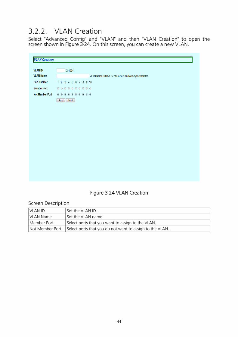
3.2.2. VLAN CreationSelect "Advanced Config" and "VLAN" and then "VLAN Creation" to open the screen shown in Figure 3-24. On this screen, you can create a new VLAN.
Figure 3-24 VLAN Creation
Screen Description
VLAN ID Set the VLAN ID.
VLAN Name Set the VLAN name.
Member Port Select ports that you want to assign to the VLAN.
Not Member Port Select ports that you do not want to assign to the VLAN.
45
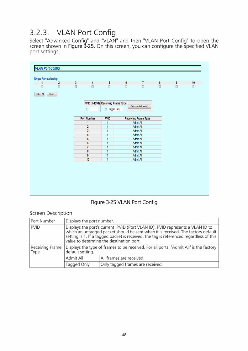
3.2.3. VLAN Port ConfigSelect "Advanced Config" and "VLAN" and then "VLAN Port Config" to open the screen shown in Figure 3-25. On this screen, you can configure the specified VLAN port settings.
Figure 3-25 VLAN Port Config
Screen Description
Port Number Displays the port number.
PVID Displays the port's current PVID (Port VLAN ID). PVID represents a VLAN ID to which an untagged packet should be sent when it is received. The factory default setting is 1. If a tagged packet is received, the tag is referenced regardless of this value to determine the destination port.
Receiving FrameType
Displays the type of frames to be received. For all ports, "Admit All" is the factory default setting.
Admit All All frames are received.
Tagged Only Only tagged frames are received.
46
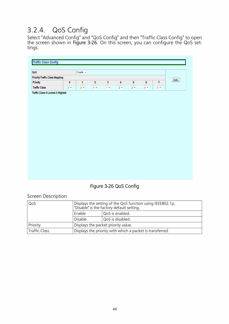
3.2.4. QoS ConfigSelect "Advanced Config" and "QoS Config" and then "Traffic Class Config" to open the screen shown in Figure 3-26. On this screen, you can configure the QoS set- tings.
Figure 3-26 QoS Config
Screen Description
QoS Displays the setting of the QoS function using IEEE802.1p."Disable" is the factory default setting.
Enable QoS is enabled.
Disable QoS is disabled.
Priority Displays the packet priority value.
Traffic Class Displays the priority with which a packet is transferred.
47
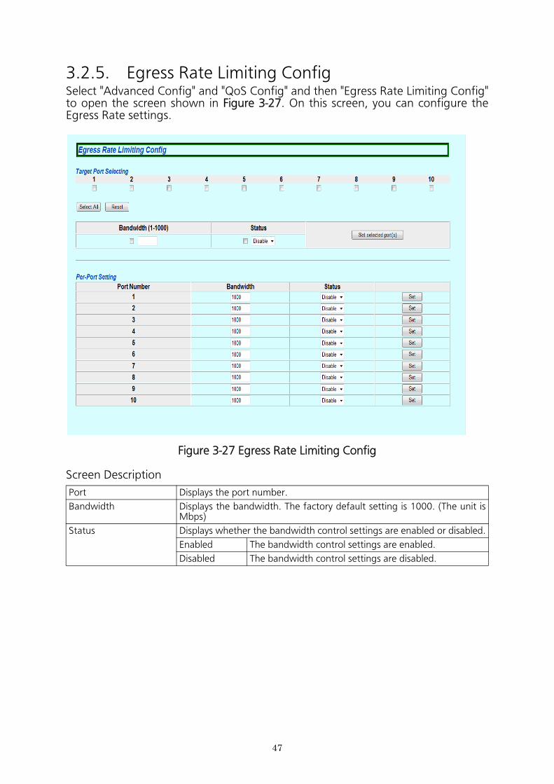
3.2.5. Egress Rate Limiting ConfigSelect "Advanced Config" and "QoS Config" and then "Egress Rate Limiting Config" to open the screen shown in Figure 3-27. On this screen, you can configure the Egress Rate settings.
Figure 3-27 Egress Rate Limiting Config
Screen Description
Port Displays the port number.
Bandwidth Displays the bandwidth. The factory default setting is 1000. (The unit is Mbps)
Status Displays whether the bandwidth control settings are enabled or disabled.
Enabled The bandwidth control settings are enabled.
Disabled The bandwidth control settings are disabled.
48
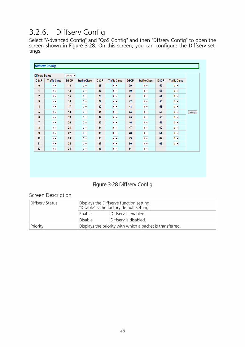
3.2.6. Diffserv ConfigSelect "Advanced Config" and "QoS Config" and then "Dffserv Config" to open the screen shown in Figure 3-28. On this screen, you can configure the Diffserv set- tings.
Figure 3-28 Diffserv Config
Screen Description
Diffserv Status Displays the Diffserve function setting."Disable" is the factory default setting.
Enable Diffserv is enabled.
Disable Diffserv is disabled.
Priority Displays the priority with which a packet is transferred.
49
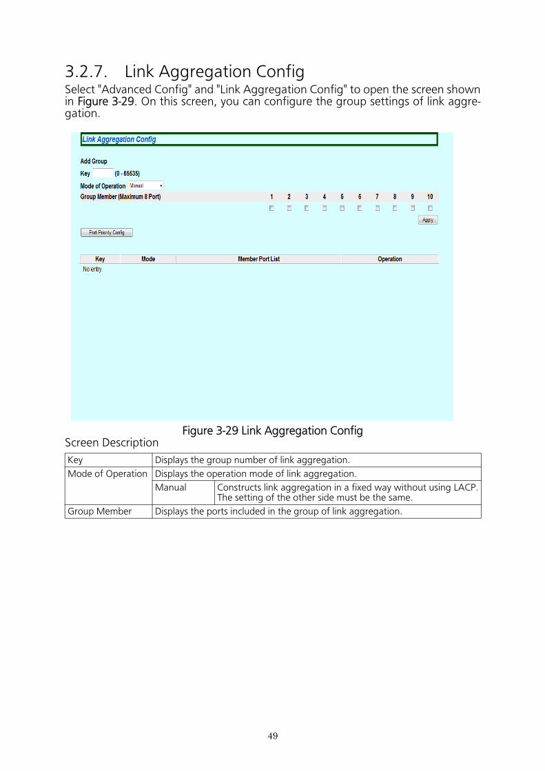
3.2.7. Link Aggregation ConfigSelect "Advanced Config" and "Link Aggregation Config" to open the screen shown in Figure 3-29. On this screen, you can configure the group settings of link aggre- gation.
Figure 3-29 Link Aggregation ConfigScreen Description
Key Displays the group number of link aggregation.
Mode of Operation Displays the operation mode of link aggregation.
Manual Constructs link aggregation in a fixed way without using LACP. The setting of the other side must be the same.
Group Member Displays the ports included in the group of link aggregation.
50
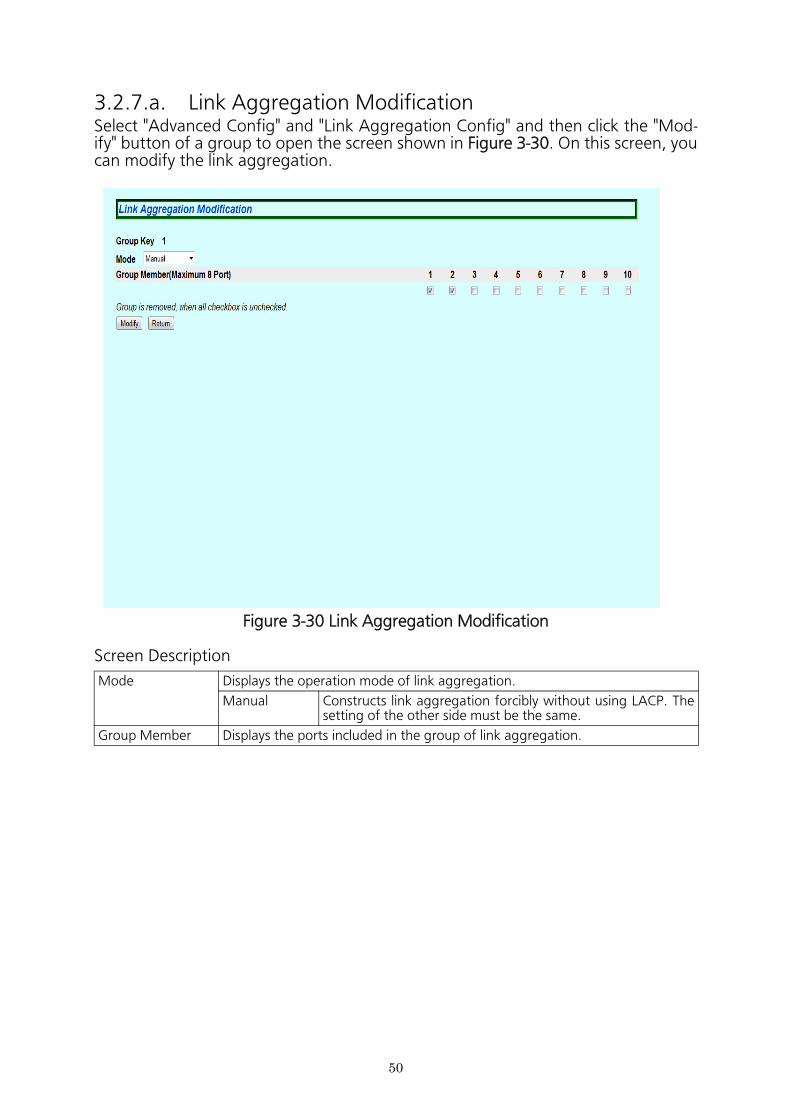
3.2.7.a. Link Aggregation ModificationSelect "Advanced Config" and "Link Aggregation Config" and then click the "Mod- ify" button of a group to open the screen shown in Figure 3-30. On this screen, you can modify the link aggregation.
Figure 3-30 Link Aggregation Modification
Screen Description
Mode Displays the operation mode of link aggregation.
Manual Constructs link aggregation forcibly without using LACP. The setting of the other side must be the same.
Group Member Displays the ports included in the group of link aggregation.
51
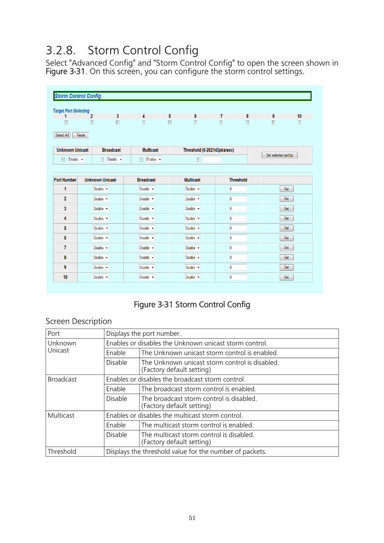
3.2.8. Storm Control ConfigSelect "Advanced Config" and "Storm Control Config" to open the screen shown in Figure 3-31. On this screen, you can configure the storm control settings.
Figure 3-31 Storm Control Config
Screen Description
Port Displays the port number.
UnknownUnicast
Enables or disables the Unknown unicast storm control.
Enable The Unknown unicast storm control is enabled.
Disable The Unknown unicast storm control is disabled.(Factory default setting)
Broadcast Enables or disables the broadcast storm control.
Enable The broadcast storm control is enabled.
Disable The broadcast storm control is disabled.(Factory default setting)
Multicast Enables or disables the multicast storm control.
Enable The multicast storm control is enabled.
Disable The multicast storm control is disabled.(Factory default setting)
Threshold Displays the threshold value for the number of packets.
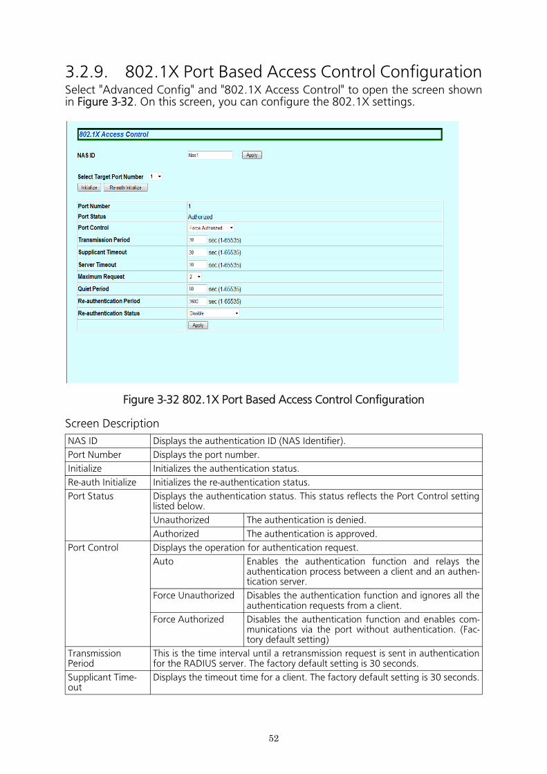
3.2.9. 802.1X Port Based Access Control ConfigurationSelect "Advanced Config" and "802.1X Access Control" to open the screen shown in Figure 3-32. On this screen, you can configure the 802.1X settings.
Figure 3-32 802.1X Port Based Access Control Configuration
Screen Description
NAS ID Displays the authentication ID (NAS Identifier).
Port Number Displays the port number.
Initialize Initializes the authentication status.
Re-auth Initialize Initializes the re-authentication status.
Port Status Displays the authentication status. This status reflects the Port Control setting listed below.
Unauthorized The authentication is denied.
Authorized The authentication is approved.
Port Control Displays the operation for authentication request.
Auto Enables the authentication function and relays the authentication process between a client and an authen- tication server.
Force Unauthorized Disables the authentication function and ignores all the authentication requests from a client.
Force Authorized Disables the authentication function and enables com- munications via the port without authentication. (Fac- tory default setting)
Transmission Period
This is the time interval until a retransmission request is sent in authentication for the RADIUS server. The factory default setting is 30 seconds.
Supplicant Time-out
Displays the timeout time for a client. The factory default setting is 30 seconds.
52

Server Timeout Displays the timeout time for an authentication server. The factory default set- ting is 30 seconds.
Maximum Request This is the maximum number of retries for retransmission in authentication. The factory default setting is 2.
Quiet Period This is the time to the next authentication request after authentication fails. The factory default setting is 60 seconds.
Re-authentication Period
This is the interval between retries for periodical re-authentication. The factory default setting is 3600 seconds.
Re-authentication Status
Displays the periodical re-authentication setting.
Enable Periodical re-authentication is enabled.
Disable Periodical re-authentication is disabled. (Factory default setting)
53
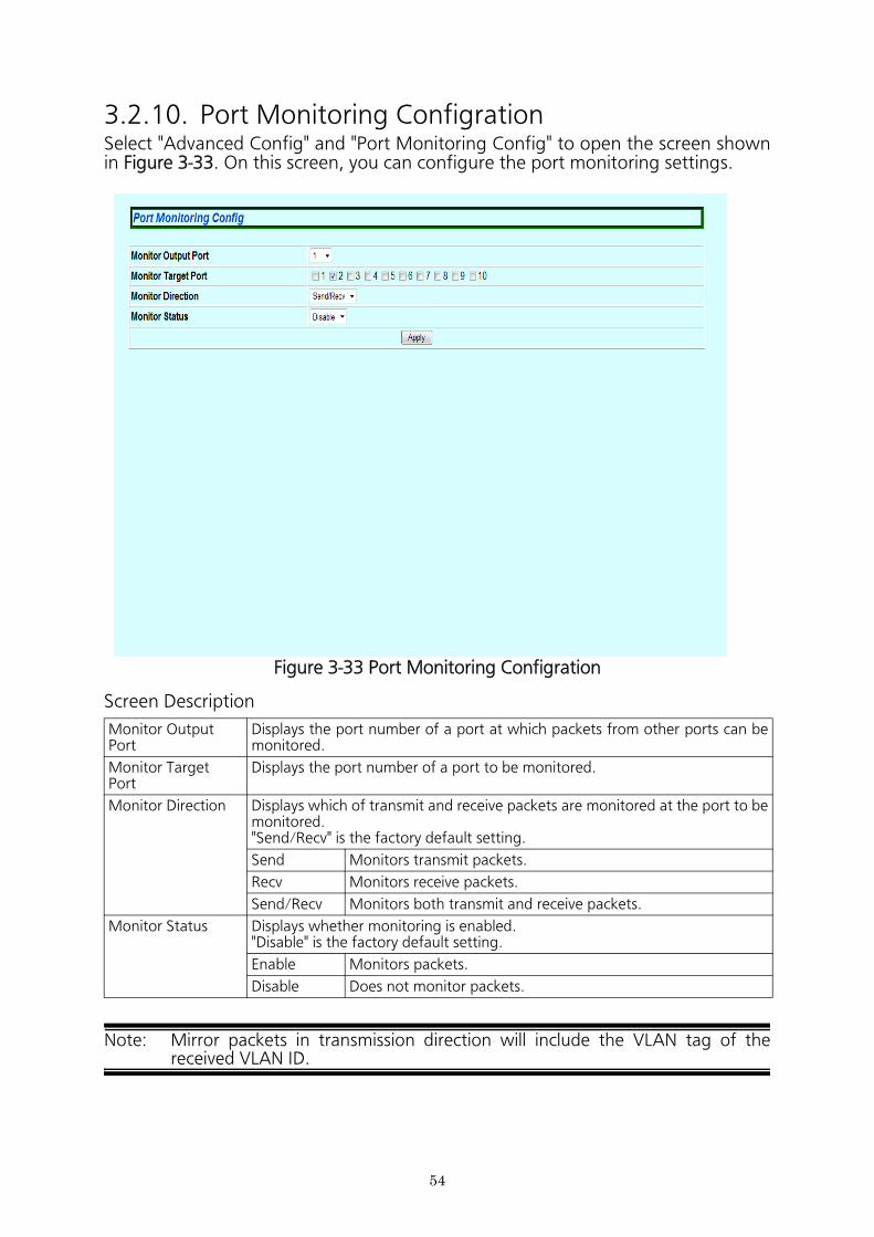
3.2.10. Port Monitoring ConfigrationSelect "Advanced Config" and "Port Monitoring Config" to open the screen shown in Figure 3-33. On this screen, you can configure the port monitoring settings.
Figure 3-33 Port Monitoring Configration
Screen Description
Note: Mirror packets in transmission direction will include the VLAN tag of the received VLAN ID.
Monitor OutputPort
Displays the port number of a port at which packets from other ports can be monitored.
Monitor TargetPort
Displays the port number of a port to be monitored.
Monitor Direction Displays which of transmit and receive packets are monitored at the port to be monitored."Send/Recv" is the factory default setting.
Send Monitors transmit packets.
Recv Monitors receive packets.
Send/Recv Monitors both transmit and receive packets.
Monitor Status Displays whether monitoring is enabled."Disable" is the factory default setting.
Enable Monitors packets.
Disable Does not monitor packets.
54

55
56
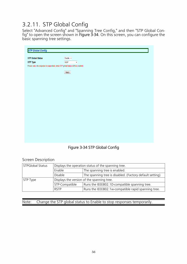
3.2.11. STP Global ConfigSelect "Advanced Config" and "Spanning Tree Config," and then "STP Global Con- fig" to open the screen shown in Figure 3-34. On this screen, you can configure the basic spanning tree settings.
Figure 3-34 STP Global Config
Screen Description
Note: Change the STP global status to Enable to stop responses temporarily.
STPGlobal Status Displays the operation status of the spanning tree.
Enable The spanning tree is enabled.
Disable The spanning tree is disabled. (Factory default setting)
STP Type Displays the version of the spanning tree.
STP-Compatible Runs the IEEE802.1D-compatible spanning tree.
RSTP Runs the IEEE802.1w-compatible rapid spanning tree.
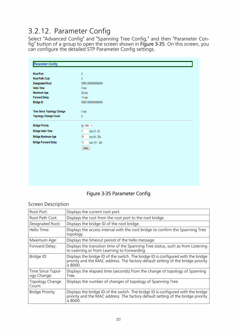
3.2.12. Parameter ConfigSelect "Advanced Config" and "Spanning Tree Config," and then "Parameter Con- fig" button of a group to open the screen shown in Figure 3-35. On this screen, you can configure the detailed STP Parameter Config settings.
Figure 3-35 Parameter Config
Screen Description
Root Port: Displays the current root port.
Root Path Cost: Displays the cost from the root port to the root bridge.
Designated Root: Displays the bridge ID of the root bridge.
Hello Time: Displays the access interval with the root bridge to confirm the Spanning Tree topology.
Maximum Age: Displays the timeout period of the hello message.
Forward Delay: Displays the transition time of the Spanning Tree status, such as from Listening to Learning or from Learning to Forwarding.
Bridge ID: Displays the bridge ID of the switch. The bridge ID is configured with the bridge priority and the MAC address. The factory default setting of the bridge priority is 8000.
Time Since Topol-ogy Change:
Displays the elapsed time (seconds) from the change of topology of Spanning Tree.
Topology Change Count:
Displays the number of changes of topology of Spanning Tree.
Bridge Priority Displays the bridge ID of the switch. The bridge ID is configured with the bridge priority and the MAC address. The factory default setting of the bridge priority is 8000.
57

Bridge Hello Time: Displays the hello time when the switch becomes the root bridge.
Bridge Maximum Age:
Displays the maximum age when the switch becomes the root bridge.
Bridge Forward Delay
Displays the forward delay when the switch becomes the root bridge.
58
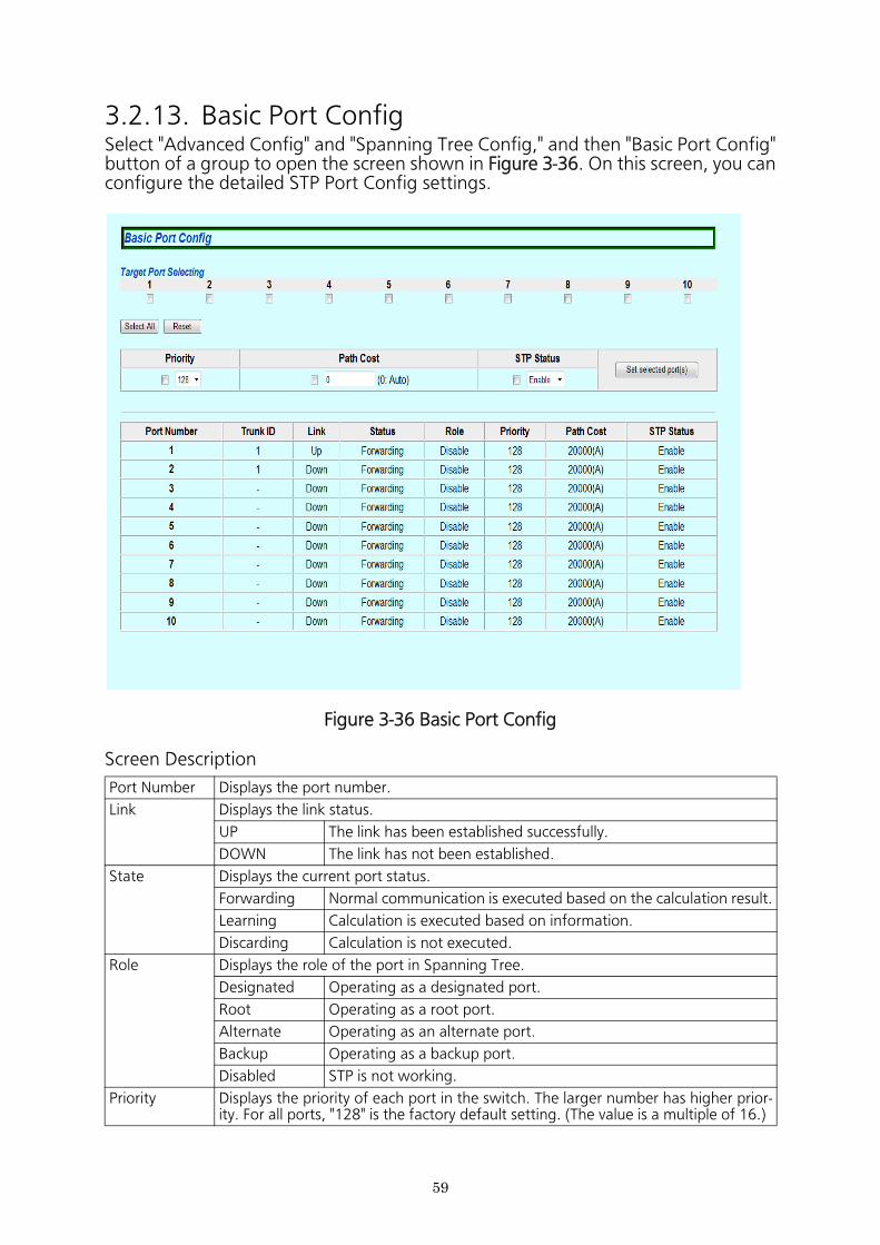
3.2.13. Basic Port ConfigSelect "Advanced Config" and "Spanning Tree Config," and then "Basic Port Config" button of a group to open the screen shown in Figure 3-36. On this screen, you can configure the detailed STP Port Config settings.
Figure 3-36 Basic Port Config
Screen Description
Port Number Displays the port number.
Link Displays the link status.
UP The link has been established successfully.
DOWN The link has not been established.
State Displays the current port status.
Forwarding Normal communication is executed based on the calculation result.
Learning Calculation is executed based on information.
Discarding Calculation is not executed.
Role Displays the role of the port in Spanning Tree.
Designated Operating as a designated port.
Root Operating as a root port.
Alternate Operating as an alternate port.
Backup Operating as a backup port.
Disabled STP is not working.
Priority Displays the priority of each port in the switch. The larger number has higher prior- ity. For all ports, "128" is the factory default setting. (The value is a multiple of 16.)
59

Path Cost Displays the cost of each port. For all ports, "Auto" is the factory default setting.In case of Auto, the cost is set automatically according to the link speed of the port.
STP Status Displays whether Spanning Tree of each port is enabled or disabled.
Enabled Spanning Tree is enabled.
Disabled Spanning Tree is disabled.
60
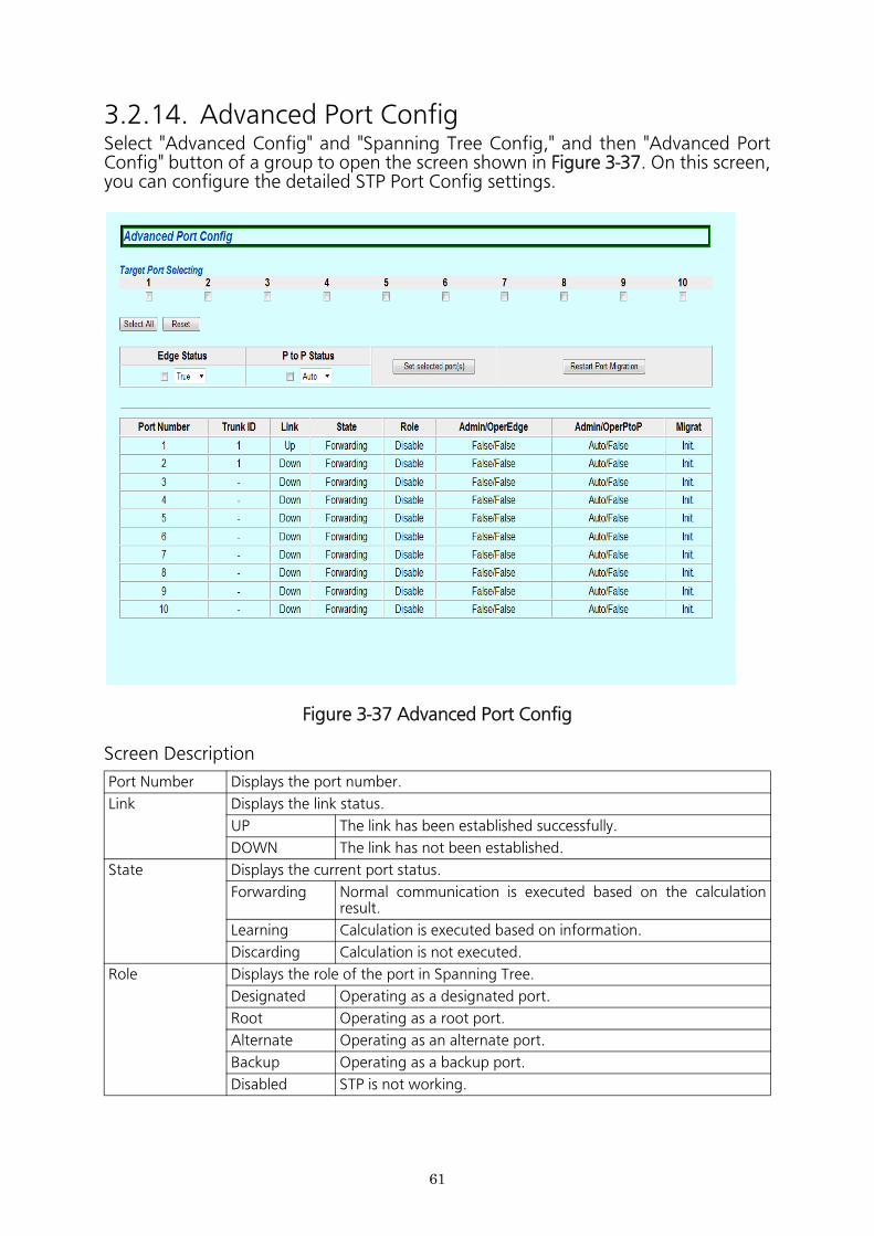
3.2.14. Advanced Port ConfigSelect "Advanced Config" and "Spanning Tree Config," and then "Advanced Port Config" button of a group to open the screen shown in Figure 3-37. On this screen, you can configure the detailed STP Port Config settings.
Figure 3-37 Advanced Port Config
Screen Description
Port Number Displays the port number.
Link Displays the link status.
UP The link has been established successfully.
DOWN The link has not been established.
State Displays the current port status.
Forwarding Normal communication is executed based on the calculation result.
Learning Calculation is executed based on information.
Discarding Calculation is not executed.
Role Displays the role of the port in Spanning Tree.
Designated Operating as a designated port.
Root Operating as a root port.
Alternate Operating as an alternate port.
Backup Operating as a backup port.
Disabled STP is not working.
61
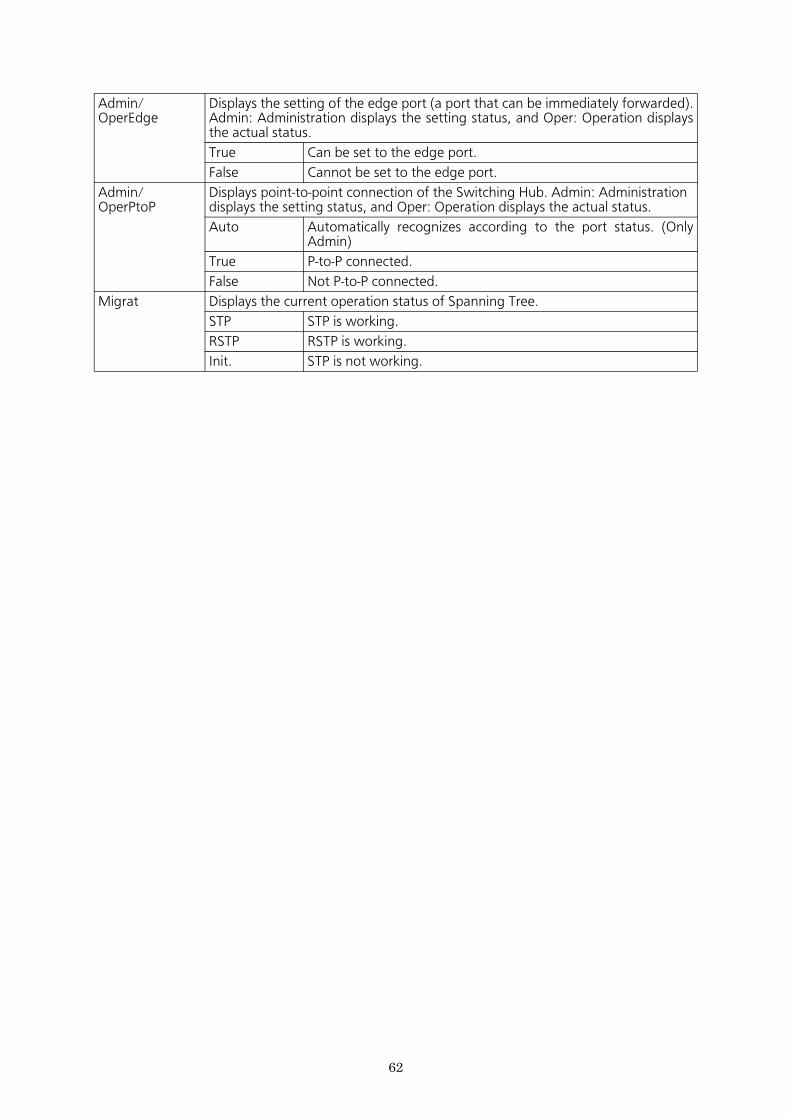
Admin/ OperEdge
Displays the setting of the edge port (a port that can be immediately forwarded). Admin: Administration displays the setting status, and Oper: Operation displays the actual status.
True Can be set to the edge port.
False Cannot be set to the edge port.
Admin/ OperPtoP
Displays point-to-point connection of the Switching Hub. Admin: Administration displays the setting status, and Oper: Operation displays the actual status.
Auto Automatically recognizes according to the port status. (Only Admin)
True P-to-P connected.
False Not P-to-P connected.
Migrat Displays the current operation status of Spanning Tree.
STP STP is working.
RSTP RSTP is working.
Init. STP is not working.
62
63
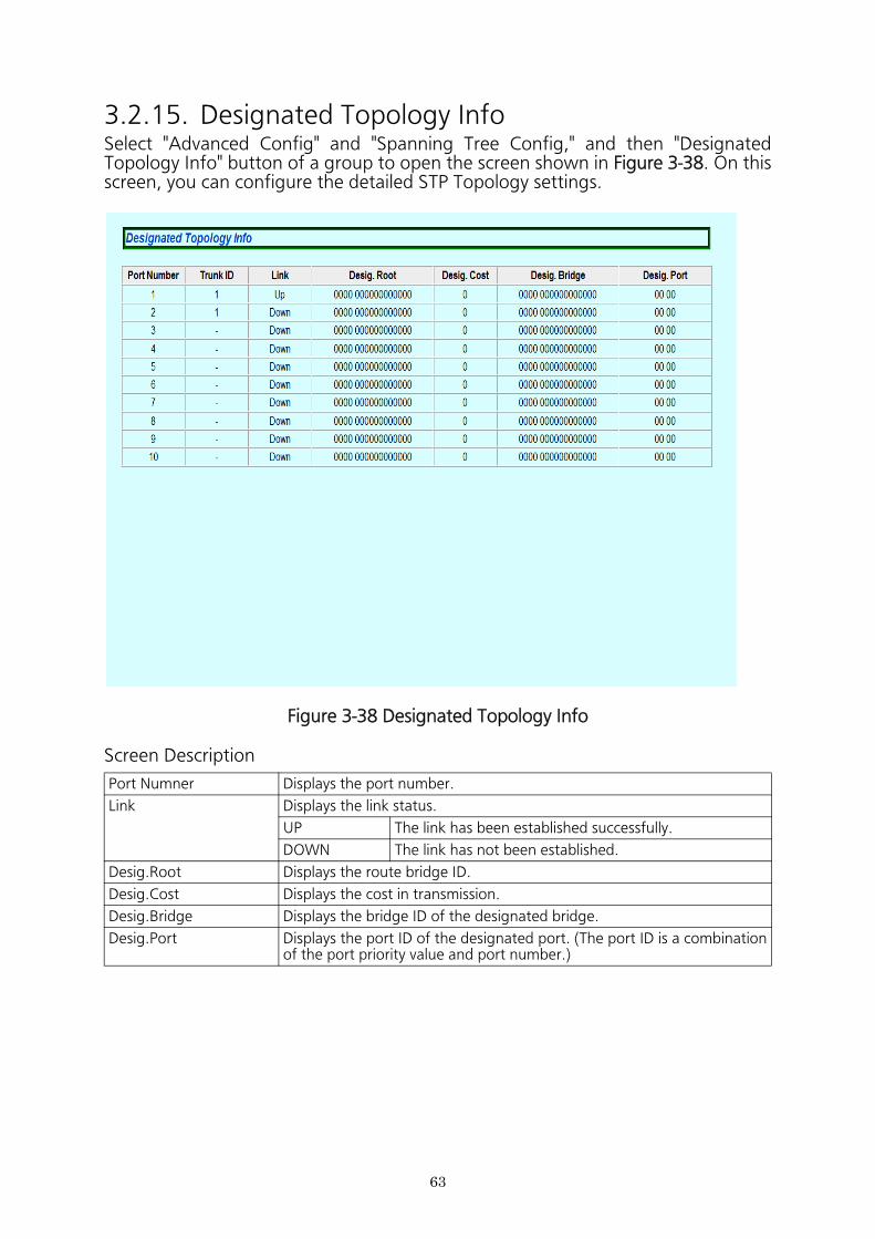
3.2.15. Designated Topology InfoSelect "Advanced Config" and "Spanning Tree Config," and then "Designated Topology Info" button of a group to open the screen shown in Figure 3-38. On this screen, you can configure the detailed STP Topology settings.
Figure 3-38 Designated Topology Info
Screen Description
Port Numner Displays the port number.
Link Displays the link status.
UP The link has been established successfully.
DOWN The link has not been established.
Desig.Root Displays the route bridge ID.
Desig.Cost Displays the cost in transmission.
Desig.Bridge Displays the bridge ID of the designated bridge.
Desig.Port Displays the port ID of the designated port. (The port ID is a combination of the port priority value and port number.)
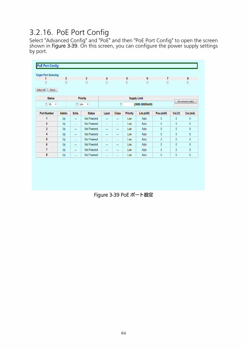
3.2.16. PoE Port Config Select "Advanced Config" and "PoE" and then "PoE Port Config" to open the screen shown in Figure 3-39. On this screen, you can configure the power supply settings by port.
Figure 3-39 PoE ポート設定
64
Screen Description
Port Number Displays the port number.
Admin. Displays whether or not power can be supplied.
Up Power can be supplied.
Down Power cannot be supplied.
Sche. Displays the PoE scheduler function status.
ON Indicates that the power supply to the PoE is turned on by the PoE scheduler.
OFF Indicates that the power supply to the PoE is turned off by the PoE scheduler.
- Indicates that the PoE scheduler is not operating.
Status Displays the power supply status.
Powered Power is supplied.
Not Powered Power is not supplied.
Overload Power supply is stopped because the power request exceeds the limit.
Class Displays the Class value detected by the classification function.
Priority Displays the priority of power supply.
Critical Represents the highest priority.
High Represents the next priority to Critical.
Low Represents no priority.
Lim.(mW) Displays the upper limit of supplied power. (in units of 200 mW)"Auto" means that the value is calculated according to the layer and class.
Pow.(mW) Displays the supplied power. (in units of 100 mW)
Vlo.(V) Displays the voltage. (in units of 1 V)
Cur.(mA) Displays the current. (in units of 1 mA)
65
66
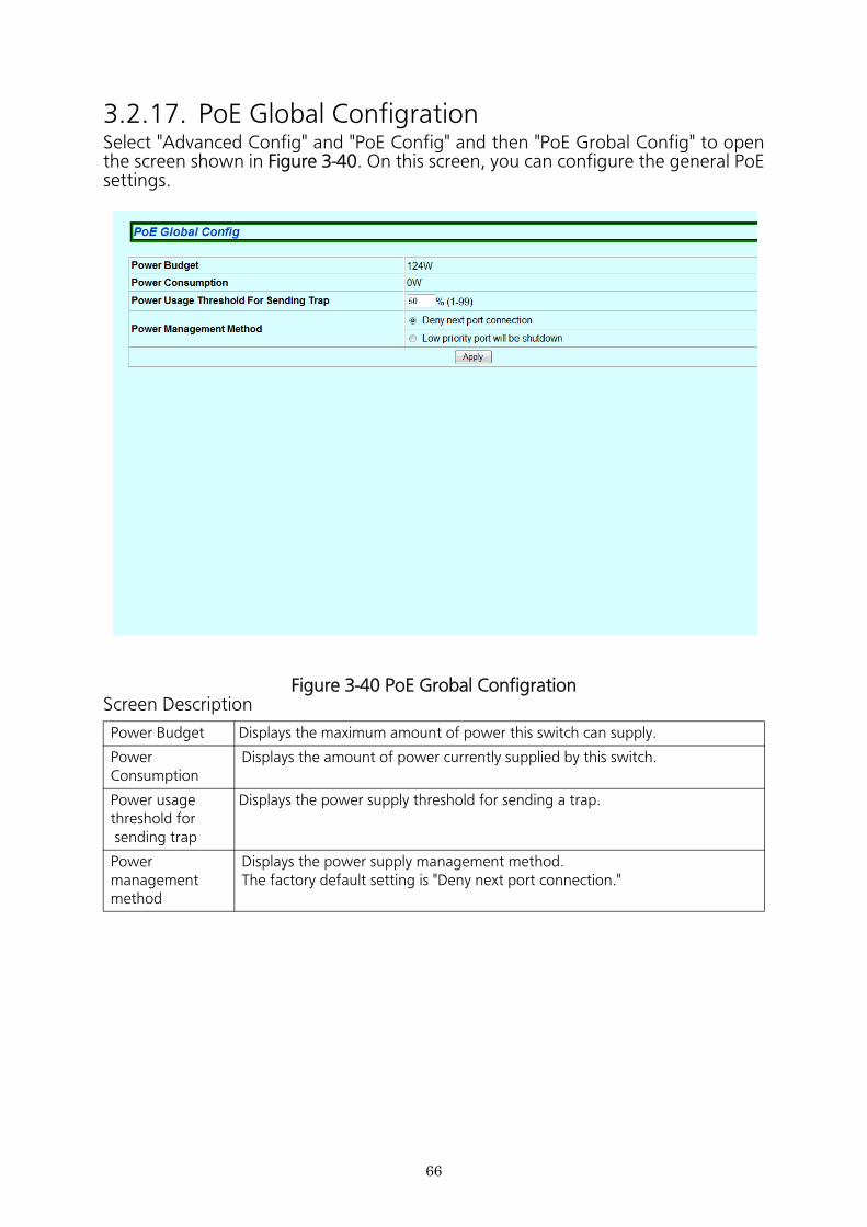
3.2.17. PoE Global Configration Select "Advanced Config" and "PoE Config" and then "PoE Grobal Config" to open the screen shown in Figure 3-40. On this screen, you can configure the general PoE settings.
Figure 3-40 PoE Grobal Configration Screen Description
Power Budget Displays the maximum amount of power this switch can supply.
Power Consumption
Displays the amount of power currently supplied by this switch.
Power usagethreshold for sending trap
Displays the power supply threshold for sending a trap.
Powermanagement method
Displays the power supply management method.The factory default setting is "Deny next port connection."
67
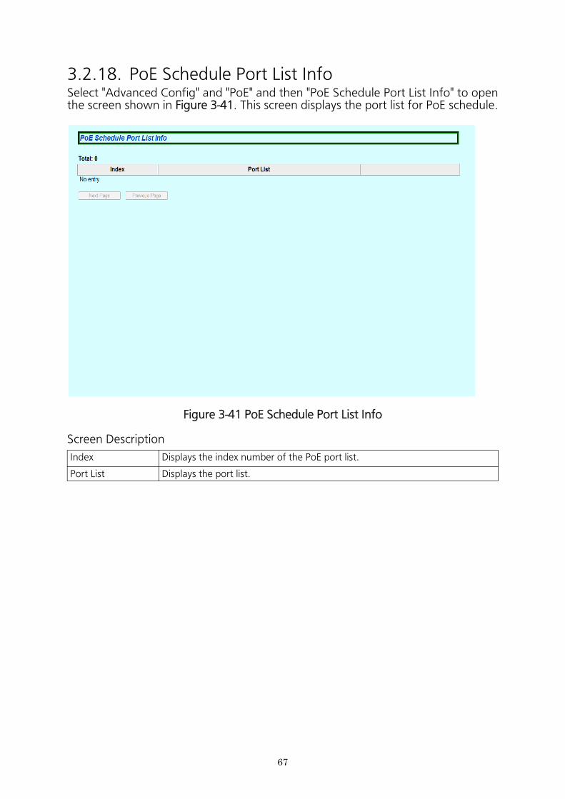
3.2.18. PoE Schedule Port List InfoSelect "Advanced Config" and "PoE" and then "PoE Schedule Port List Info" to open the screen shown in Figure 3-41. This screen displays the port list for PoE schedule.
Figure 3-41 PoE Schedule Port List Info
Screen Description
Index Displays the index number of the PoE port list.
Port List Displays the port list.
68
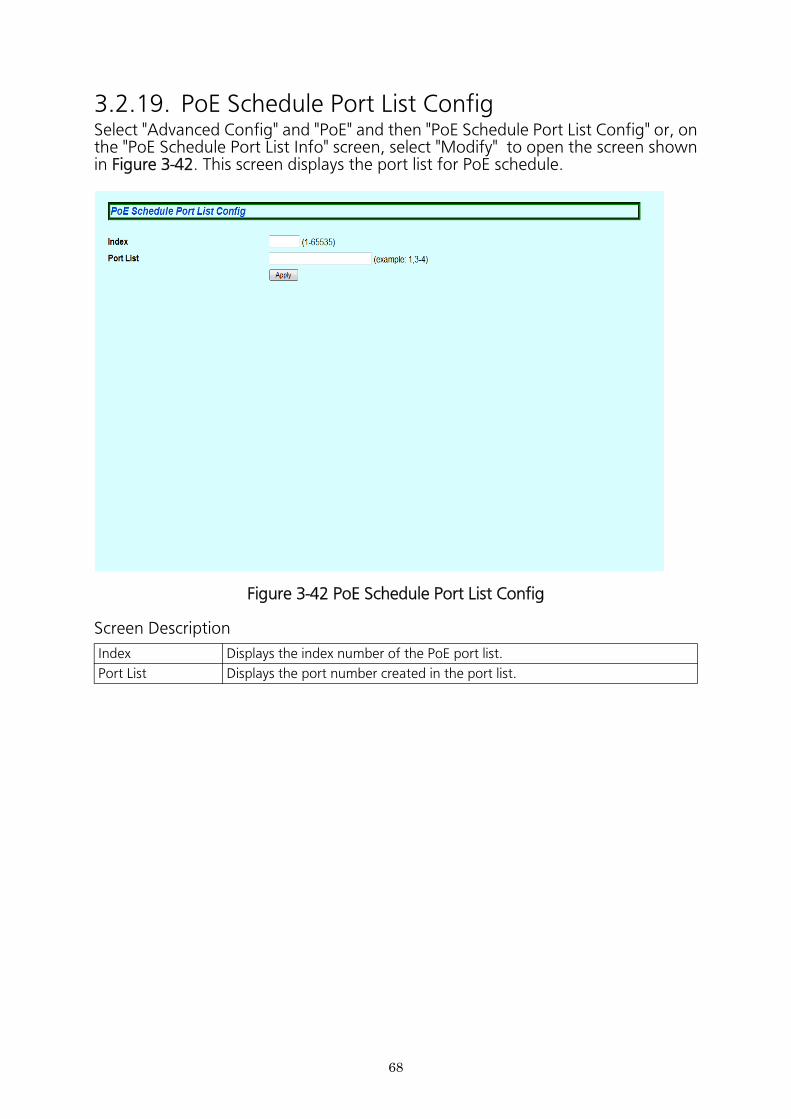
3.2.19. PoE Schedule Port List ConfigSelect "Advanced Config" and "PoE" and then "PoE Schedule Port List Config" or, on the "PoE Schedule Port List Info" screen, select "Modify" to open the screen shown in Figure 3-42. This screen displays the port list for PoE schedule.
Figure 3-42 PoE Schedule Port List Config
Screen Description
Index Displays the index number of the PoE port list.
Port List Displays the port number created in the port list.
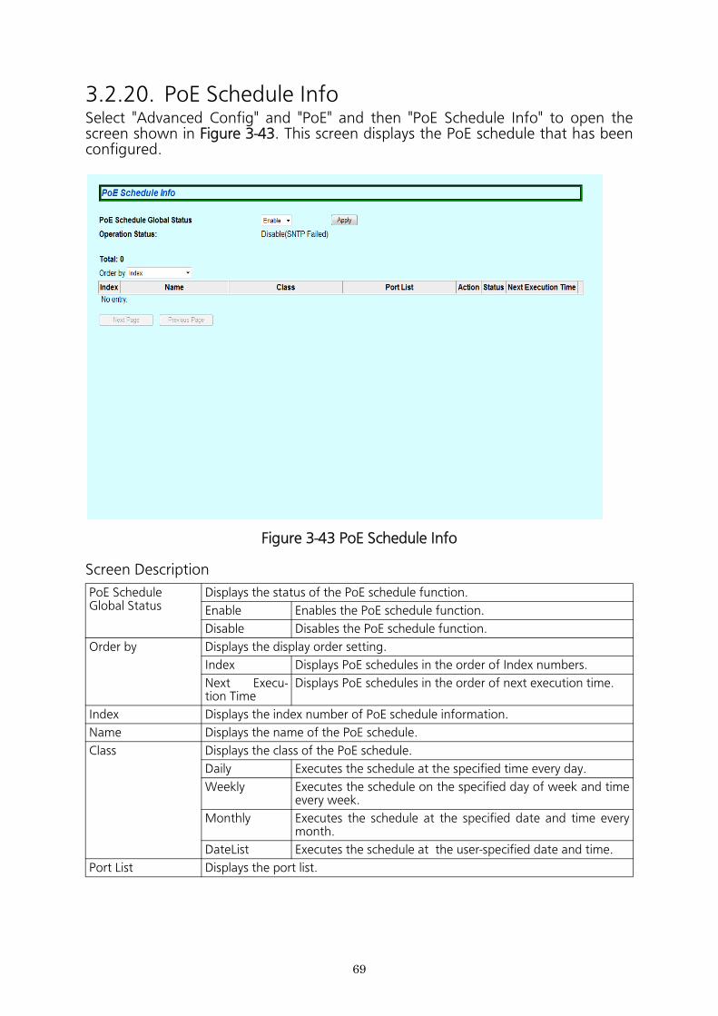
3.2.20. PoE Schedule InfoSelect "Advanced Config" and "PoE" and then "PoE Schedule Info" to open the screen shown in Figure 3-43. This screen displays the PoE schedule that has been configured.
Figure 3-43 PoE Schedule Info
Screen Description
PoE Schedule Global Status
Displays the status of the PoE schedule function.
Enable Enables the PoE schedule function.
Disable Disables the PoE schedule function.
Order by Displays the display order setting.
Index Displays PoE schedules in the order of Index numbers.
Next Execu- tion Time
Displays PoE schedules in the order of next execution time.
Index Displays the index number of PoE schedule information.
Name Displays the name of the PoE schedule.
Class Displays the class of the PoE schedule.
Daily Executes the schedule at the specified time every day.
Weekly Executes the schedule on the specified day of week and time every week.
Monthly Executes the schedule at the specified date and time every month.
DateList Executes the schedule at the user-specified date and time.
Port List Displays the port list.
69

Active Displays the action of the PoE schedule.
ON Turns on PoE.
OFF Turns off PoE.
OFF/ON Turns off and on PoE (RESTART).
Status Displays the status of the PoE schedule function of the port.
Enable Enables the PoE schedule function of the port.
Disable Disables the PoE schedule function of the port.
Next Execution Time
Displays the date and time when the next schedule is executed.
70
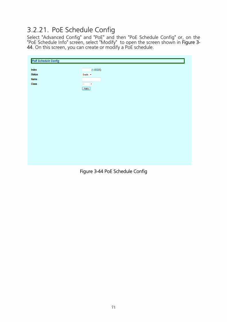
3.2.21. PoE Schedule ConfigSelect "Advanced Config" and "PoE" and then "PoE Schedule Config" or, on the "PoE Schedule Info" screen, select "Modify" to open the screen shown in Figure 3- 44. On this screen, you can create or modify a PoE schedule.
Figure 3-44 PoE Schedule Config
71
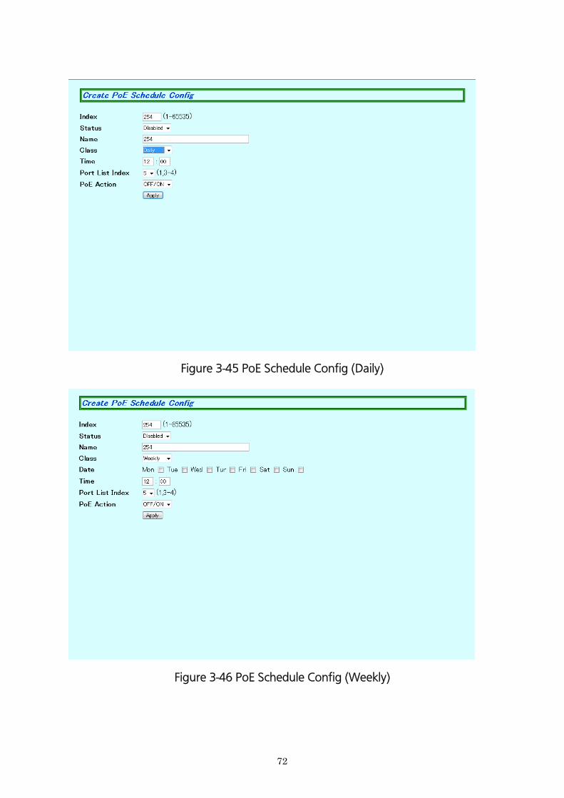
Figure 3-45 PoE Schedule Config (Daily)
Figure 3-46 PoE Schedule Config (Weekly)
72
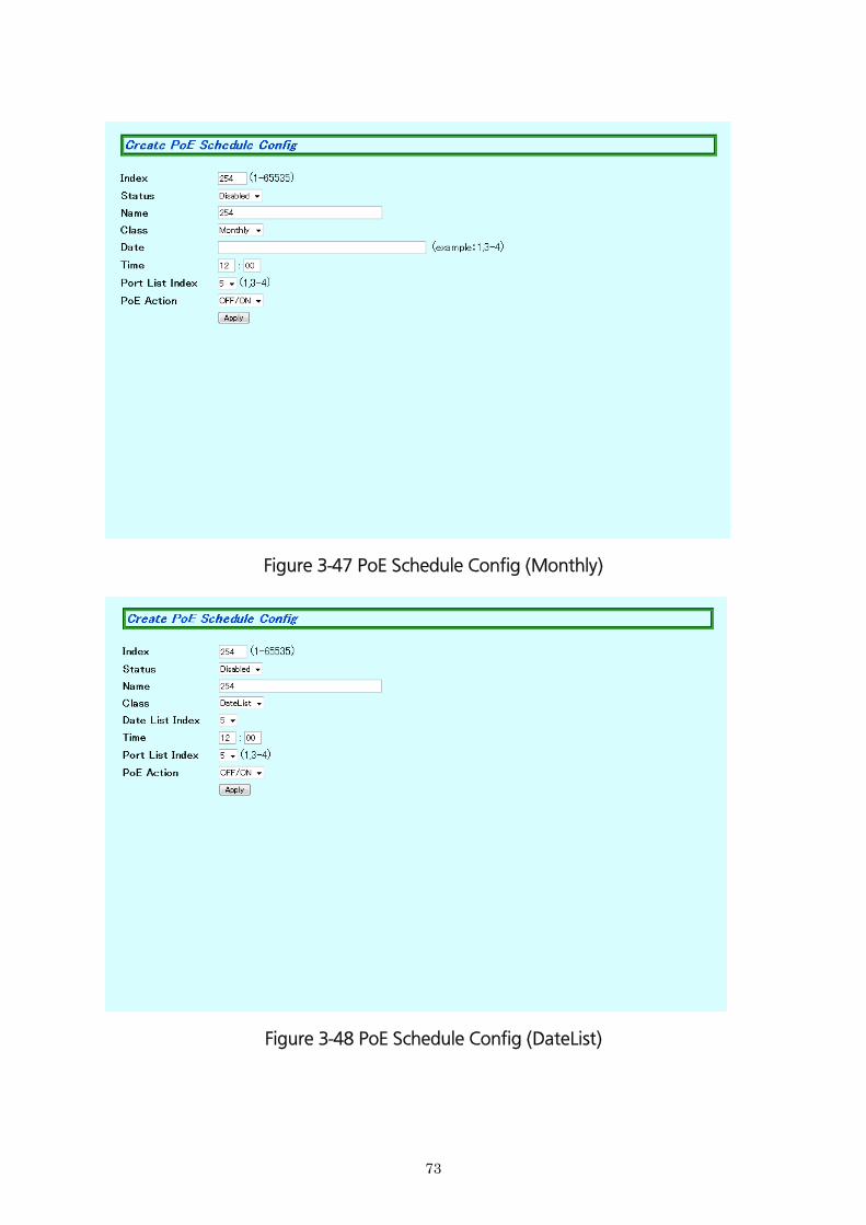
Figure 3-47 PoE Schedule Config (Monthly)
Figure 3-48 PoE Schedule Config (DateList)
73
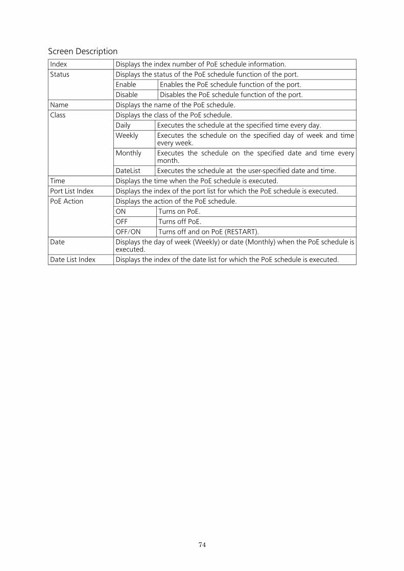
Screen Description
Index Displays the index number of PoE schedule information.
Status Displays the status of the PoE schedule function of the port.
Enable Enables the PoE schedule function of the port.
Disable Disables the PoE schedule function of the port.
Name Displays the name of the PoE schedule.
Class Displays the class of the PoE schedule.
Daily Executes the schedule at the specified time every day.
Weekly Executes the schedule on the specified day of week and time every week.
Monthly Executes the schedule on the specified date and time every month.
DateList Executes the schedule at the user-specified date and time.
Time Displays the time when the PoE schedule is executed.
Port List Index Displays the index of the port list for which the PoE schedule is executed.
PoE Action Displays the action of the PoE schedule.
ON Turns on PoE.
OFF Turns off PoE.
OFF/ON Turns off and on PoE (RESTART).
Date Displays the day of week (Weekly) or date (Monthly) when the PoE schedule is executed.
Date List Index Displays the index of the date list for which the PoE schedule is executed.
74
75
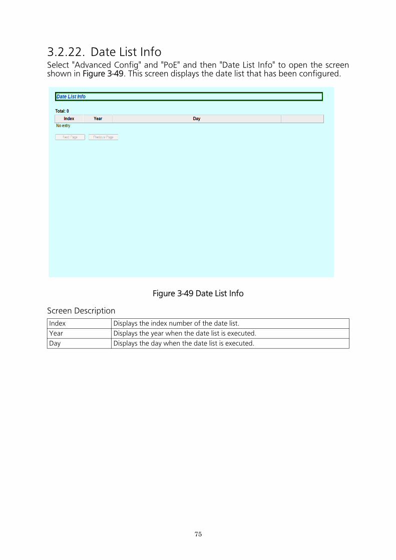
3.2.22. Date List InfoSelect "Advanced Config" and "PoE" and then "Date List Info" to open the screen shown in Figure 3-49. This screen displays the date list that has been configured.
Figure 3-49 Date List Info
Screen Description
Index Displays the index number of the date list.
Year Displays the year when the date list is executed.
Day Displays the day when the date list is executed.
76
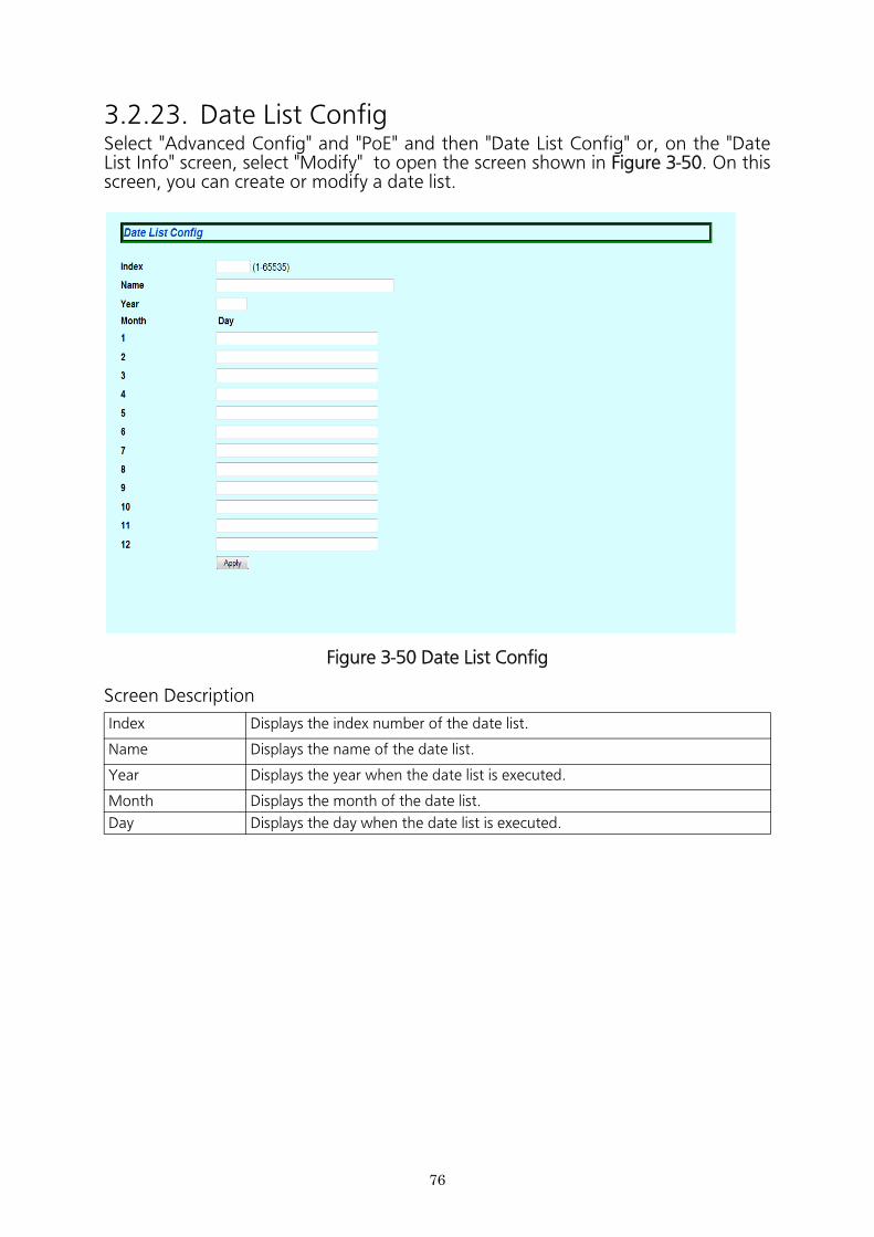
3.2.23. Date List ConfigSelect "Advanced Config" and "PoE" and then "Date List Config" or, on the "Date List Info" screen, select "Modify" to open the screen shown in Figure 3-50. On this screen, you can create or modify a date list.
Figure 3-50 Date List Config
Screen Description
Index Displays the index number of the date list.
Name Displays the name of the date list.
Year Displays the year when the date list is executed.
Month Displays the month of the date list.
Day Displays the day when the date list is executed.
77
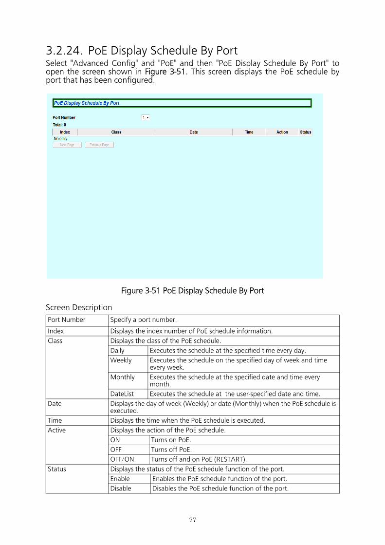
3.2.24. PoE Display Schedule By PortSelect "Advanced Config" and "PoE" and then "PoE Display Schedule By Port" to open the screen shown in Figure 3-51. This screen displays the PoE schedule by port that has been configured.
Figure 3-51 PoE Display Schedule By Port
Screen Description
Port Number Specify a port number.
Index Displays the index number of PoE schedule information.
Class Displays the class of the PoE schedule.
Daily Executes the schedule at the specified time every day.
Weekly Executes the schedule on the specified day of week and time every week.
Monthly Executes the schedule at the specified date and time every month.
DateList Executes the schedule at the user-specified date and time.
Date Displays the day of week (Weekly) or date (Monthly) when the PoE schedule is executed.
Time Displays the time when the PoE schedule is executed.
Active Displays the action of the PoE schedule.
ON Turns on PoE.
OFF Turns off PoE.
OFF/ON Turns off and on PoE (RESTART).
Status Displays the status of the PoE schedule function of the port.
Enable Enables the PoE schedule function of the port.
Disable Disables the PoE schedule function of the port.
78
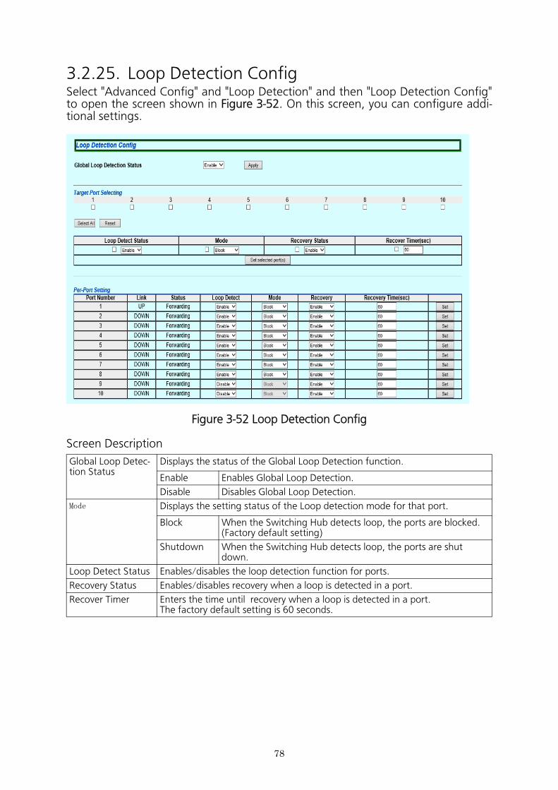
3.2.25. Loop Detection ConfigSelect "Advanced Config" and "Loop Detection" and then "Loop Detection Config" to open the screen shown in Figure 3-52. On this screen, you can configure addi- tional settings.
Figure 3-52 Loop Detection Config
Screen Description
Global Loop Detec-tion Status
Displays the status of the Global Loop Detection function.
Enable Enables Global Loop Detection.
Disable Disables Global Loop Detection.
Mode Displays the setting status of the Loop detection mode for that port.
Block When the Switching Hub detects loop, the ports are blocked.(Factory default setting)
Shutdown When the Switching Hub detects loop, the ports are shutdown.
Loop Detect Status Enables/disables the loop detection function for ports.
Recovery Status Enables/disables recovery when a loop is detected in a port.
Recover Timer Enters the time until recovery when a loop is detected in a port.The factory default setting is 60 seconds.
79
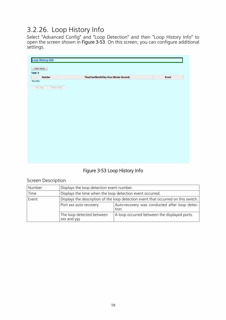
3.2.26. Loop History InfoSelect "Advanced Config" and "Loop Detection" and then "Loop History Info" to open the screen shown in Figure 3-53. On this screen, you can configure additional settings.
Figure 3-53 Loop History Info
Screen Description
Number Displays the loop detection event number.
Time Displays the time when the loop detection event occurred.
Event Displays the description of the loop detection event that occurred on this switch.
Port xxx auto recovery Auto-recovery was conducted after loop detec- tion.
The loop detected between xxx and yyy
A loop occurred between the displayed ports.
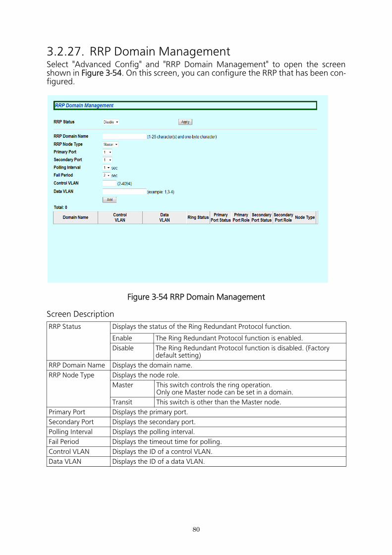
3.2.27. RRP Domain ManagementSelect "Advanced Config" and "RRP Domain Management" to open the screen shown in Figure 3-54. On this screen, you can configure the RRP that has been con- figured.
Figure 3-54 RRP Domain Management
Screen Description
RRP Status Displays the status of the Ring Redundant Protocol function.
Enable The Ring Redundant Protocol function is enabled.
Disable The Ring Redundant Protocol function is disabled. (Factory default setting)
RRP Domain Name Displays the domain name.
RRP Node Type Displays the node role.
Master This switch controls the ring operation.Only one Master node can be set in a domain.
Transit This switch is other than the Master node.
Primary Port Displays the primary port.
Secondary Port Displays the secondary port.
Polling Interval Displays the polling interval.
Fail Period Displays the timeout time for polling.
Control VLAN Displays the ID of a control VLAN.
Data VLAN Displays the ID of a data VLAN.
80
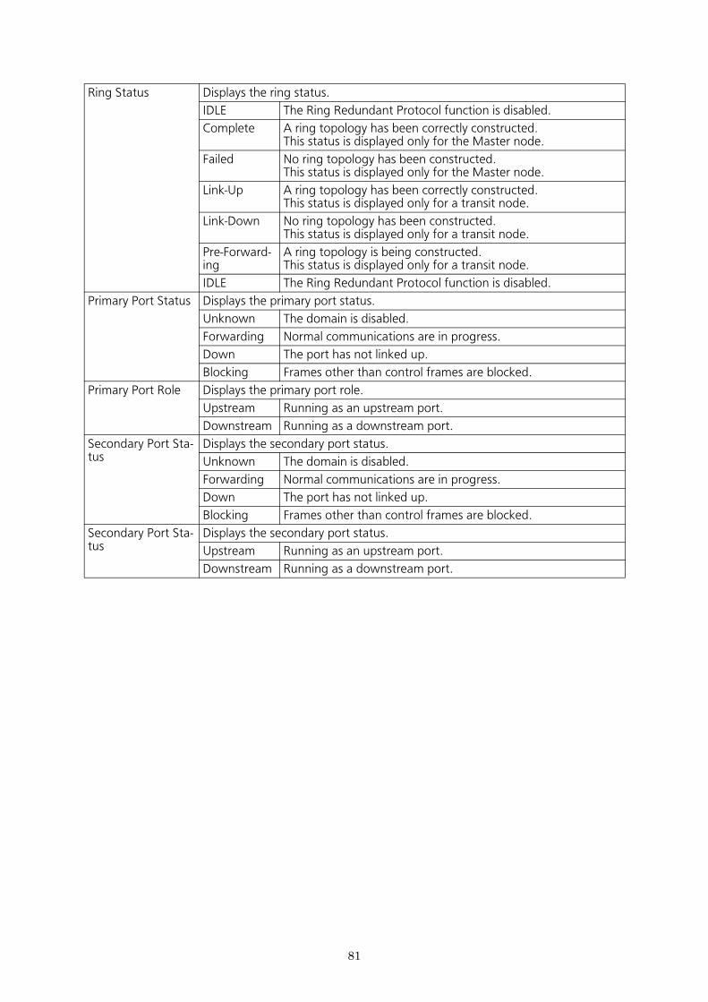
Ring Status Displays the ring status.
IDLE The Ring Redundant Protocol function is disabled.
Complete A ring topology has been correctly constructed.This status is displayed only for the Master node.
Failed No ring topology has been constructed.This status is displayed only for the Master node.
Link-Up A ring topology has been correctly constructed.This status is displayed only for a transit node.
Link-Down No ring topology has been constructed.This status is displayed only for a transit node.
Pre-Forward-ing
A ring topology is being constructed.This status is displayed only for a transit node.
IDLE The Ring Redundant Protocol function is disabled.
Primary Port Status Displays the primary port status.
Unknown The domain is disabled.
Forwarding Normal communications are in progress.
Down The port has not linked up.
Blocking Frames other than control frames are blocked.
Primary Port Role Displays the primary port role.
Upstream Running as an upstream port.
Downstream Running as a downstream port.
Secondary Port Sta-tus
Displays the secondary port status.
Unknown The domain is disabled.
Forwarding Normal communications are in progress.
Down The port has not linked up.
Blocking Frames other than control frames are blocked.
Secondary Port Sta-tus
Displays the secondary port status.
Upstream Running as an upstream port.
Downstream Running as a downstream port.
81
82
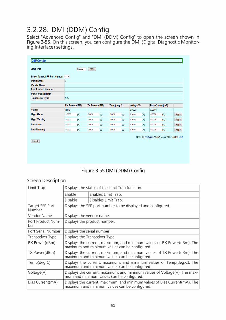
3.2.28. DMI (DDM) ConfigSelect "Advanced Config" and "DMI (DDM) Config" to open the screen shown in Figure 3-55. On this screen, you can configure the DMI (Digital Diagnostic Monitor- ing Interface) settings.
Figure 3-55 DMI (DDM) Config
Screen Description
Limit Trap Displays the status of the Limit Trap function.
Enable Enables Limit Trap.
Disable Disables Limit Trap.
Target SFP Port Number
Displays the SFP port number to be displayed and configured.
Vendor Name Displays the vendor name.
Port Product Num-ber
Displays the product number.
Port Serial Number Displays the serial number.
Transceiver Type Displays the Transceiver Type.
RX Power(dBm) Displays the current, maximum, and minimum values of RX Power(dBm). The maximum and minimum values can be configured.
TX Power(dBm) Displays the current, maximum, and minimum values of TX Power(dBm). The maximum and minimum values can be configured.
Temp(deg.C) Displays the current, maximum, and minimum values of Temp(deg.C). The maximum and minimum values can be configured.
Voltage(V) Displays the current, maximum, and minimum values of Voltage(V). The maxi- mum and minimum values can be configured.
Bias Current(mA) Displays the current, maximum, and minimum values of Bias Current(mA). The maximum and minimum values can be configured.
83
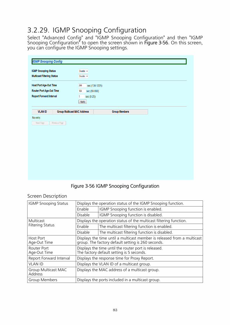
3.2.29. IGMP Snooping ConfigurationSelect "Advanced Config" and "IGMP Snooping Configuration" and then "IGMP Snooping Configuration" to open the screen shown in Figure 3-56. On this screen, you can configure the IGMP Snooping settings.
Figure 3-56 IGMP Snooping Configuration
Screen Description
IGMP Snooping Status Displays the operation status of the IGMP Snooping function.
Enable IGMP Snooping function is enabled.
Disable IGMP Snooping function is disabled.
MulticastFiltering Status
Displays the operation status of the multicast filtering function.
Enable The multicast filtering function is enabled.
Disable The multicast filtering function is disabled.
Host PortAge-Out Time
Displays the time until a multicast member is released from a multicast group. The factory default setting is 260 seconds.
Router PortAge-Out Time
Displays the time until the router port is released.The factory default setting is 5 seconds.
Report Forward Interval Displays the response time for Proxy Report.
VLAN ID Displays the VLAN ID of a multicast group.
Group Multicast MAC Address
Displays the MAC address of a multicast group.
Group Members Displays the ports included in a multicast group.
84
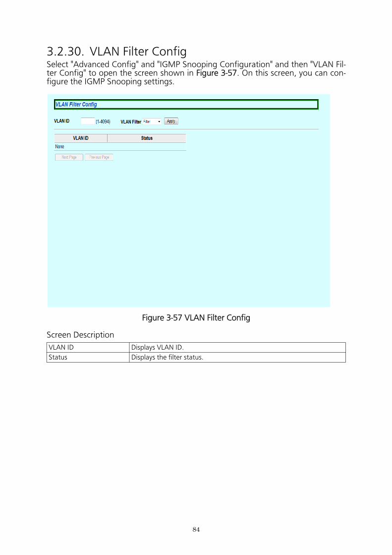
3.2.30. VLAN Filter ConfigSelect "Advanced Config" and "IGMP Snooping Configuration" and then "VLAN Fil- ter Config" to open the screen shown in Figure 3-57. On this screen, you can con- figure the IGMP Snooping settings.
Figure 3-57 VLAN Filter Config
Screen Description
VLAN ID Displays VLAN ID.
Status Displays the filter status.
85
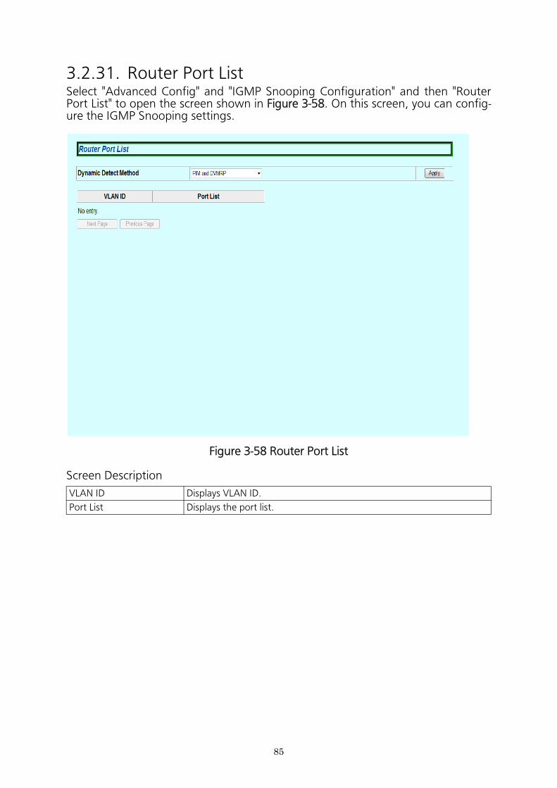
3.2.31. Router Port ListSelect "Advanced Config" and "IGMP Snooping Configuration" and then "Router Port List" to open the screen shown in Figure 3-58. On this screen, you can config- ure the IGMP Snooping settings.
Figure 3-58 Router Port List
Screen Description
VLAN ID Displays VLAN ID.
Port List Displays the port list.
86
3.3. System Tools
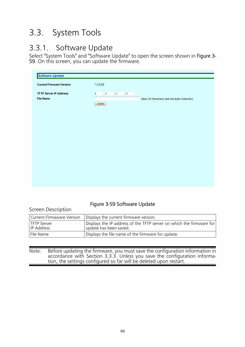
3.3.1. Software UpdateSelect "System Tools" and "Software Update" to open the screen shown in Figure 3- 59. On this screen, you can update the firmware.
Figure 3-59 Software UpdateScreen Description
Note: Before updating the firmware, you must save the configuration information in accordance with Section 3.3.3. Unless you save the configuration informa- tion, the settings configured so far will be deleted upon restart.
Current Firmaware Version Displays the current firmware version.
TFTP Server IP Address
Displays the IP address of the TFTP server on which the firmware for update has been saved.
File Name Displays the file name of the firmware for update.
87
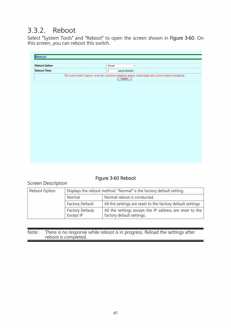
3.3.2. RebootSelect "System Tools" and "Reboot" to open the screen shown in Figure 3-60. On this screen, you can reboot this switch.
Figure 3-60 RebootScreen Description
Note: There is no response while reboot is in progress. Reload the settings after reboot is completed.
Reboot Option Displays the reboot method. "Normal" is the factory default setting.
Normal Normal reboot is conducted.
Factory Default All the settings are reset to the factory default settings.
Factory Defauly Except IP
All the settings except the IP address are reset to the factory default settings.
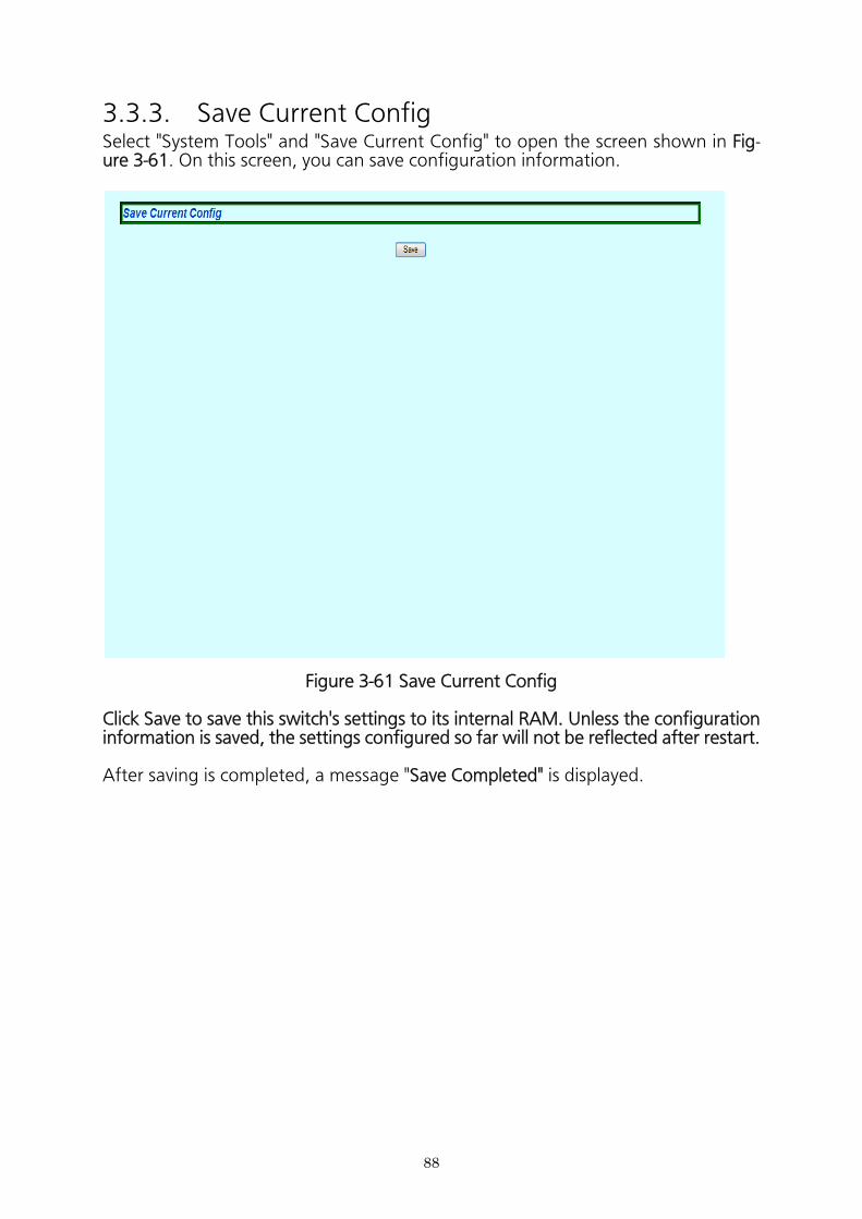
88
3.3.3. Save Current ConfigSelect "System Tools" and "Save Current Config" to open the screen shown in Fig- ure 3-61. On this screen, you can save configuration information.
Figure 3-61 Save Current Config
Click Save to save this switch's settings to its internal RAM. Unless the configuration information is saved, the settings configured so far will not be reflected after restart.
After saving is completed, a message "Save Completed" is displayed.
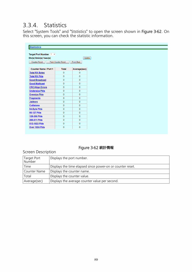
3.3.4. StatisticsSelect "System Tools" and "Ststistics" to open the screen shown in Figure 3-62. On this screen, you can check the statistic information.
Figure 3-62 統計情報Screen Description
Target PortNumber
Displays the port number.
Time Displays the time elapsed since power-on or counter reset.
Counter Name Displays the counter name.
Total Displays the counter value.
Average(sec) Displays the average counter value per second.
89
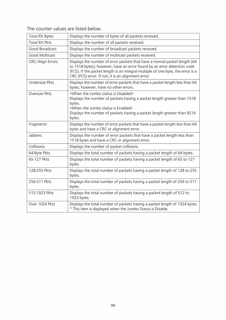
The counter values are listed below.
Total RX Bytes Displays the number of bytes of all packets received.
Total RX Pkts Displays the number of all packets received.
Good Broadcast Displays the number of broadcast packets received.
Good Multicast Displays the number of multicast packets received.
CRC/Align Errors Displays the number of error packets that have a normal packet length (64 to 1518 bytes); however, have an error found by an error detection code (FCS). If the packet length is an integral multiple of one byte, the error is a CRC (FCS) error. If not, it is an alignment error.
Undersize Pkts Displays the number of error packets that have a packet length less than 64 bytes; however, have no other errors.
Oversize Pkts <When the Jumbo status is Disabled>Displays the number of packets having a packet length greater than 1518 bytes.<When the Jumbo status is Enabled>Displays the number of packets having a packet length greater than 9216 bytes.
Fragments Displays the number of error packets that have a packet length less than 64 bytes and have a CRC or alignment error.
Jabbers Displays the number of error packets that have a packet length less than 1518 bytes and have a CRC or alignment error.
Collisions Displays the number of packet collisions.
64-Byte Pkts Displays the total number of packets having a packet length of 64 bytes.
65-127 Pkts Displays the total number of packets having a packet length of 65 to 127 bytes.
128-255 Pkts Displays the total number of packets having a packet length of 128 to 255 bytes.
256-511 Pkts Displays the total number of packets having a packet length of 256 to 511 bytes.
512-1023 Pkts Displays the total number of packets having a packet length of 512 to 1023 bytes.
Over 1024 Pkts Displays the total number of packets having a packet length of 1024 bytes.* This item is displayed when the Jumbo Status is Disable.
90
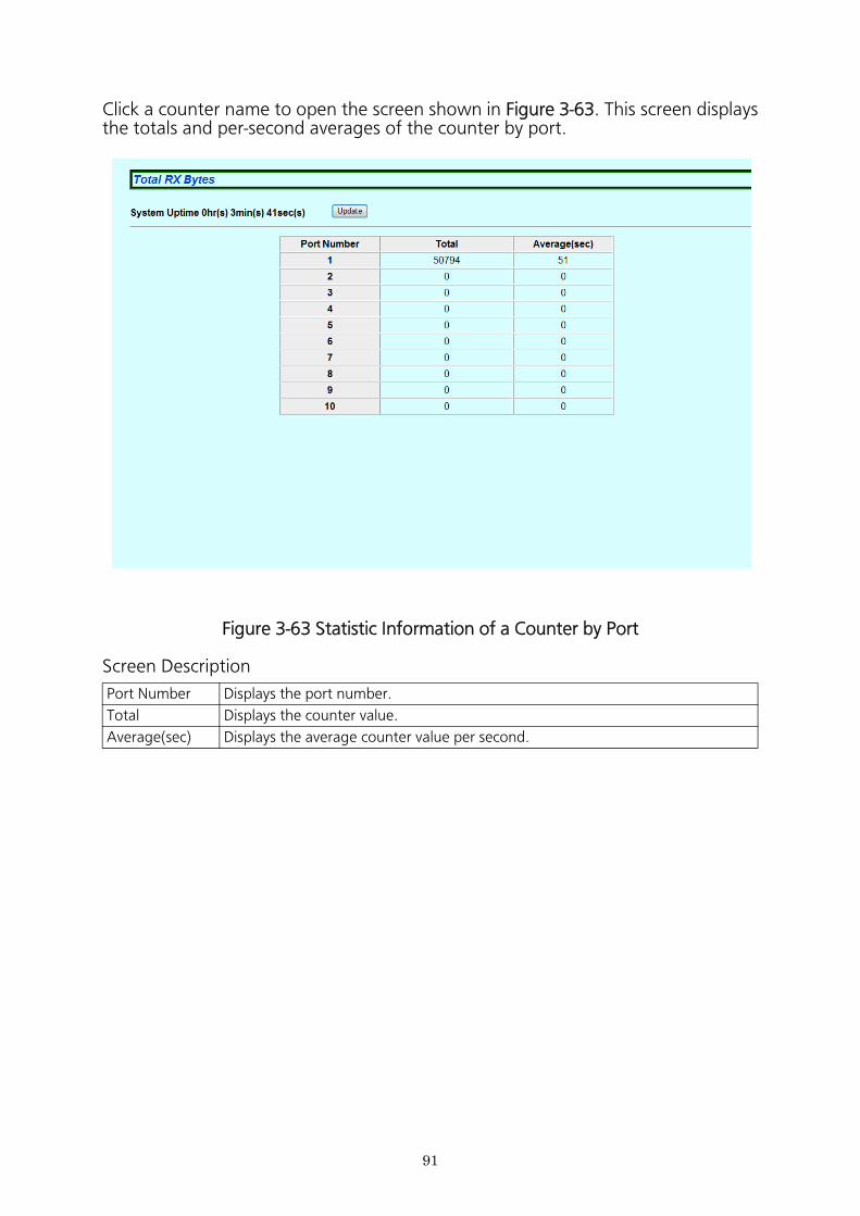
Figure 3-63 Statistic Information of a Counter by Port
Screen Description
Port Number Displays the port number.
Total Displays the counter value.
Average(sec) Displays the average counter value per second.
91
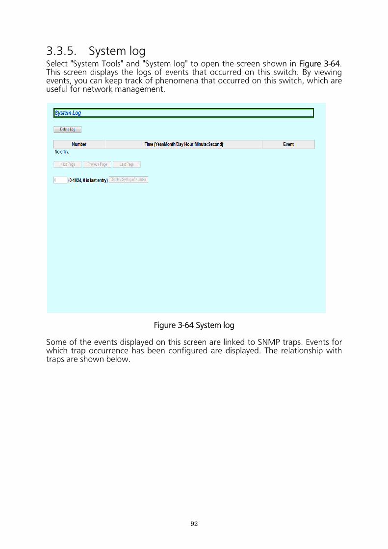
3.3.5. System logSelect "System Tools" and "System log" to open the screen shown in Figure 3-64. This screen displays the logs of events that occurred on this switch. By viewing events, you can keep track of phenomena that occurred on this switch, which are useful for network management.
Figure 3-64 System log
Some of the events displayed on this screen are linked to SNMP traps. Events for which trap occurrence has been configured are displayed. The relationship with traps are shown below.
92
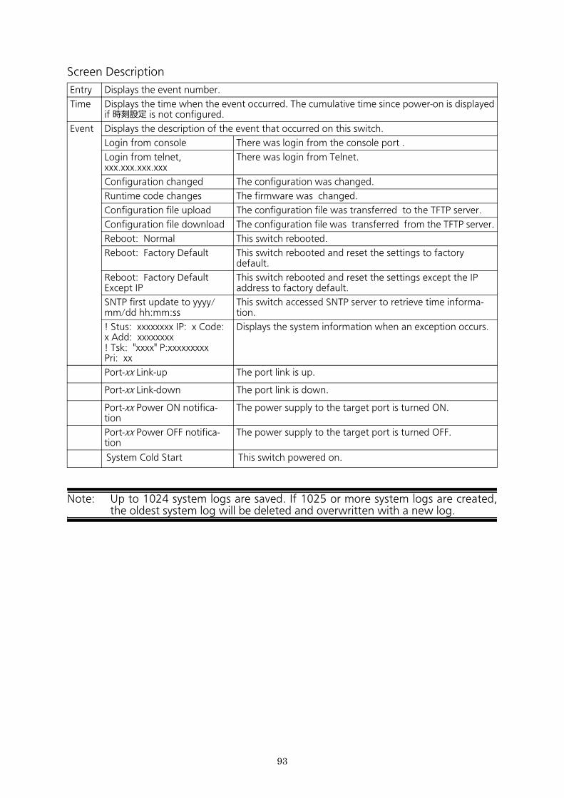
Screen Description
Note: Up to 1024 system logs are saved. If 1025 or more system logs are created, the oldest system log will be deleted and overwritten with a new log.
Entry Displays the event number.
Time Displays the time when the event occurred. The cumulative time since power-on is displayed if 時刻設定 is not configured.
Event Displays the description of the event that occurred on this switch.
Login from console There was login from the console port .
Login from telnet, xxx.xxx.xxx.xxx
There was login from Telnet.
Configuration changed The configuration was changed.
Runtime code changes The firmware was changed.
Configuration file upload The configuration file was transferred to the TFTP server.
Configuration file download The configuration file was transferred from the TFTP server.
Reboot: Normal This switch rebooted.
Reboot: Factory Default This switch rebooted and reset the settings to factory default.
Reboot: Factory Default Except IP
This switch rebooted and reset the settings except the IP address to factory default.
SNTP first update to yyyy/mm/dd hh:mm:ss
This switch accessed SNTP server to retrieve time informa-tion.
! Stus: xxxxxxxx IP: x Code: x Add: xxxxxxxx! Tsk: "xxxx" P:xxxxxxxxx Pri: xx
Displays the system information when an exception occurs.
Port-xx Link-up The port link is up.
Port-xx Link-down The port link is down.
Port-xx Power ON notifica-tion
The power supply to the target port is turned ON.
Port-xx Power OFF notifica-tion
The power supply to the target port is turned OFF.
System Cold Start This switch powered on.
93
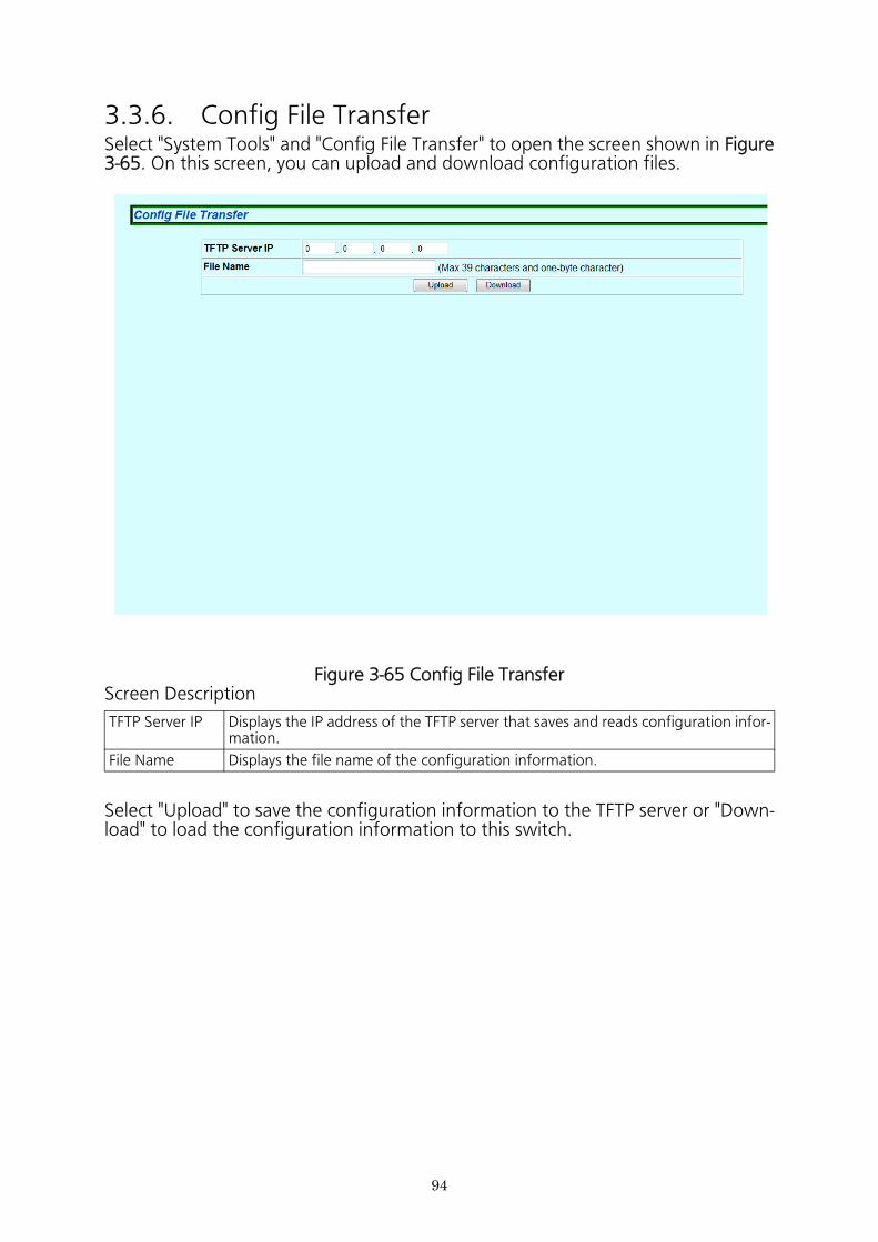
94
3.3.6. Config File TransferSelect "System Tools" and "Config File Transfer" to open the screen shown in Figure 3-65. On this screen, you can upload and download configuration files.
Figure 3-65 Config File TransferScreen Description
Select "Upload" to save the configuration information to the TFTP server or "Down- load" to load the configuration information to this switch.
TFTP Server IP Displays the IP address of the TFTP server that saves and reads configuration infor- mation.
File Name Displays the file name of the configuration information.
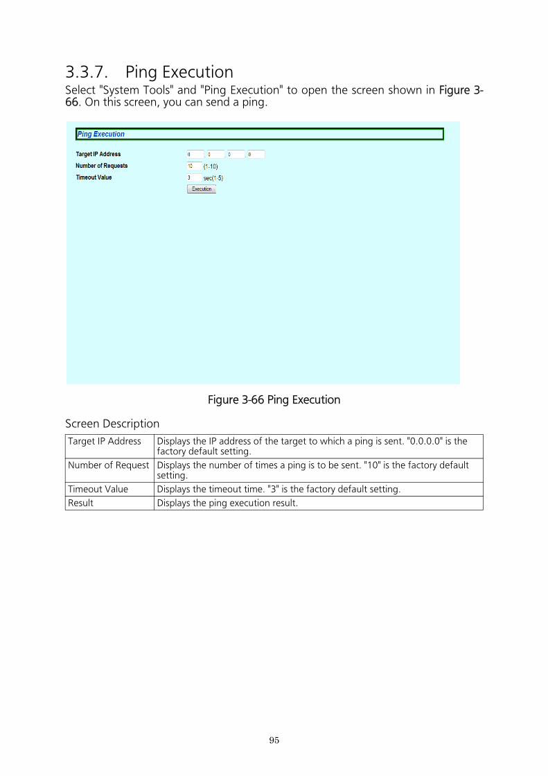
95
3.3.7. Ping ExecutionSelect "System Tools" and "Ping Execution" to open the screen shown in Figure 3- 66. On this screen, you can send a ping.
Figure 3-66 Ping Execution
Screen Description
Target IP Address Displays the IP address of the target to which a ping is sent. "0.0.0.0" is the factory default setting.
Number of Request Displays the number of times a ping is to be sent. "10" is the factory default setting.
Timeout Value Displays the timeout time. "3" is the factory default setting.
Result Displays the ping execution result.
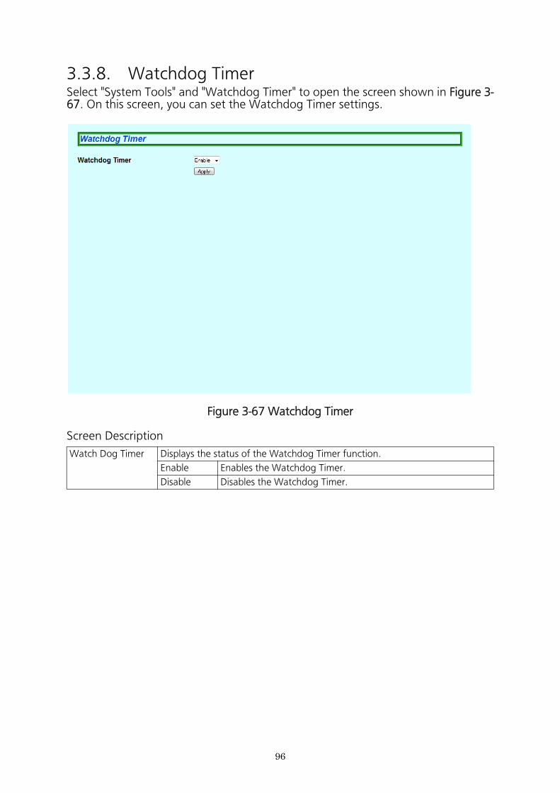
96
3.3.8. Watchdog TimerSelect "System Tools" and "Watchdog Timer" to open the screen shown in Figure 3- 67. On this screen, you can set the Watchdog Timer settings.
Figure 3-67 Watchdog Timer
Screen Description
Watch Dog Timer Displays the status of the Watchdog Timer function.
Enable Enables the Watchdog Timer.
Disable Disables the Watchdog Timer.

97
Refer to "Operation Manual for Menu Interface" for your switching hub to read the specifications.
4. Specifications
98
The following are points to note when using the easy IP address setup function.
[Known compatible software]Panasonic Corporation "Easy IP Setup" V3.01/V4.00/V4.24R00Panasonic System Networks Co., Ltd. "Easy Config" Ver3.10R00Panasonic Eco Solutions Networks Co., Ltd. "ZEQUOASSIST" Ver. 2.0.3.0
[User-settable items]* IP address, subnet mask, and default gateway* System name
* This item can be configured only with the software "Easy Config."In the software, the item is displayed as "Camera name."
[Restrictions]* The time for accepting setting changes is limited to 20 minutes after power-on
to ensure security.However, you can change settings regardless of the time limit if the IP address, subnet mask, default gateway, user name, and password values are set to fac- tory defaults.* Even after the time limit is reached, you can check the current settings dis-
played in a list.* The following function of the software "Easy Config" cannot be used.
- "Auto setup function"
*Please contact your manufacturer for information about network cameras.
5. Easy IP Address Setup Function
99
If you find any problems, please take the following steps to check.◆ LED
■ The POWER LED (Power) is not lit.● Check if the power cord is disconnected. Please confirm that the power
cord is securely connected to the power port● Is the Switching Hub being used at a temperature between 0 and 50 ℃
?Use the Switching Hub in its operating temperature range.Note: If used at a temperature out of the operating temperature range, the
protection equipment becomes activated and PoE power supply stops.The default operating temperature range is 0 to 50 ℃ .
■ The Port LED is not lit in Status mode.● Is the cable correctly connected to the target port?● Is the cable appropriate to use?● Is the terminal connected to the relevant port conforming with 10BASE-
T,100BASE-TX, or 1000BASE-T standerd?● Auto-negotiation may have feiled.Check the port settings of this Switching
Hub or the terminal settings.■ The Port LED (Left) lights in failed.
Check the port settings of this Switching Hub or the terminal settings.■ LOOP HISTORY LED Blinks in orange.
● This is no notify that there is a port in which a loop is occurring, or has been removedwithin 3days.
◆ Communications are slow.● Are the communication speed and mode settings correct? If the proper
communication mode signal cannot be obtained, apply half-duplex mode. Please reconfirm autonegotiation setting.
● Is not the utillization ratio of the network to which this Switching Hub is connected too high? Try separating this Switching Hub from the network.
◆ Communications fail.● Is the link-up correct? If embedded saving mode is set to Full, change the
setting to Half or Disabled.● Is the Port LED (right) lit in orange? If the Port LED (right) lit in orange, the
port is shut down by the loop detection function. Eliminate the loop con- nection of the device connected to the port first, and then wait longer than the time required for automatic recovery from the shutdown by the loop detection function, or release the port shutdown from the setting screen.
6. Troubleshooting
1. Warranty cardA warranty card is included in the operating instructions (paper) provided with this switch. Be sure to confirm that the date of purchase, dealer (company) name, etc., have been entered in the warranty card and then receive it from the shop. Read it carefully, and then keep it in a safe place. The warranty period is one year from the date of purchase.
2. Repair requestIf a problem is not solved even after taking the steps shown in the "Trouble- shooting" section in this manual, please use the Memo shown on the next page and make a repair request with the following information to your dealer.
◆ Product name ◆ Model number◆ Product serial number (an 11-digit number attached on the back of the
product.)◆ Firmware version (The number after "Ver." labeled on the unit package)◆ Problem status (Please give as concrete information as possible.)● Within the warranty period:
Repair service will be provided in accordance with the conditions stipulated in the warranty card.Please bring your product and warranty card in your dealer.
● After the warranty period expires:If our check determines that your product is repairable, a chargeable repair service is available upon your request.Please contact your dealer.
3. Inquiries about after-sales service and the productContact contact your dealer, or call/fax the following number.
7. After-sales Service
100
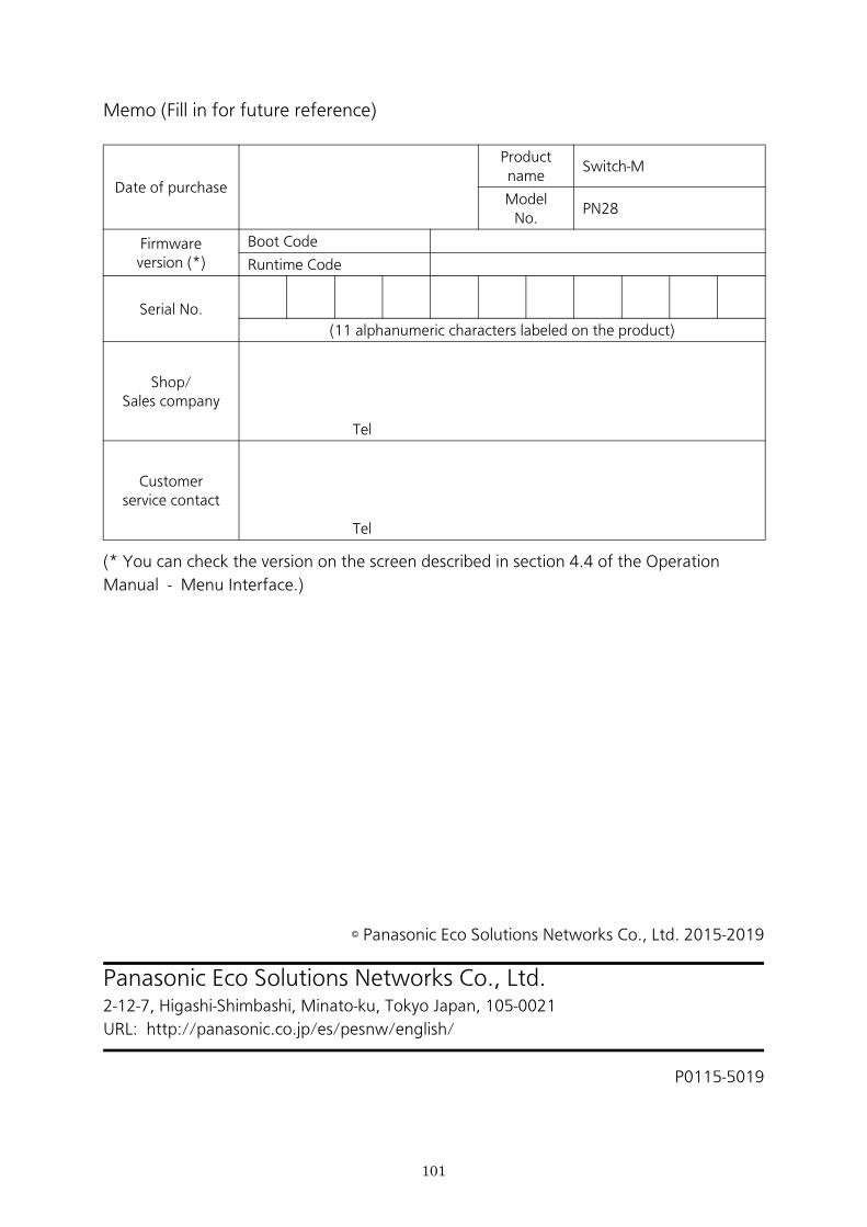
Date of purchase
Product name
Switch-M
ModelNo.
PN28
Firmwareversion (*)
Boot Code
Runtime Code
Serial No.
(11 alphanumeric characters labeled on the product)
Shop/Sales company
Tel
Customerservice contact
Tel
Memo (Fill in for future reference)
(* You can check the version on the screen described in section 4.4 of the Operation
Manual - Menu Interface.)
© Panasonic Eco Solutions Networks Co., Ltd. 2015-2019
Panasonic Eco Solutions Networks Co., Ltd.2-12-7, Higashi-Shimbashi, Minato-ku, Tokyo Japan, 105-0021
URL: http://panasonic.co.jp/es/pesnw/english/
P0115-5019
101