operation manual model t 480 - big hanna
TRANSCRIPT

© Susteco AB Big Hanna Operational Manual T480_O_15004_Susteco_ en
‘Let your food waste grow!’
OPERATION MANUAL
MODEL
T480
© Susteco AB Big Hanna Operational Manual T480_O_15004_Susteco_ en
ORIGINAL This manual must be read before the Big Hanna Composter is used. The owner of the Big Hanna Composter shall ensure that all employees are informed about all relevant contents in this manual before usage. This manual shall be stored in a manner so that it is kept safe for the lifespan of the composter. This manual informs the customer on how to use the composter. The supplier takes no responsibility for damage or breakdown caused by usage of the composter in any way other than is described in this manual. © Susteco AB
1 BASIC FACTS
1.1 THE DIFFERENT MODELS 1.2 MANUFACTURER 1.3 WARRANTY 1.4 CERTIFICATION
1.4.1 CE-MARK 1.5 CAUTION LABELS 1.6 FUNCTION, RANGE OF APPLICATION AND LIMITATIONS OF USE
1.6.1 FUNCTION 1.6.2 STORAGE 1.6.3 LIMITATIONS IN SIZE OF MATERIAL AND CAPACITY 1.6.4 DEFINITIONS 1.6.5 RANGE OF APPLICATION AND LIMITATIONS OF USE 1.6.6 SITE SPECIFIC REGULATIONS
1.7 SAFE AND CORRECT USE 1.7.1 BIOHAZARD FROM COMPOSTING ACTIVITIES 1.7.2 PATHOGENS IN THE FOOD WASTE 1.7.3 SLIPS AND TRIPS DUE TO SPILLAGE 1.7.4 PEST CONTROL 1.7.5 OPERATIONAL RISKS INVOLVING MACHINERY 1.7.6 OPERATIONAL TRAINING
1.8 SUPPLY DATA FOR ELECTRICITY 1.9 CAPACITY – EQUIPMENT – MEASUREMENTS – ELECTRICAL SUPPLY – ENERGY
CONSUMPTION 1.10 USAGE OF COMPOST MATERIAL
1.10.1 SECONDARY TREATMENT OF THE COMPOST MATERIAL 1.11 PERFORMANCE DATA AND METHODS OF MEASUREMENT
1.11.1 MEASUREMENT ANALYSIS COMPOST MATERIAL 1.12 NOISE, SMELL, SEWAGE
1.12.1 NOISE 1.12.2 SMELL 1.12.3 DRAIN TO SEWAGE
1.13 SAFETY INFORMATION 1.13.1 MASTER SWITCH 1.13.2 SAFETY EQUIPMENT 1.13.3 WARNING – INFEED HOPPER LID 1.13.4 INSPECTION DOOR(S) OPEN 1.13.5 EMERGENCY STOP 1.13.6 SAFETY COMPONENTS
1.14 SAFETY WARNINGS AND PROTECTION 1.15 INSTALLATION AND TRANSPORTATION
1.15.1 CLIMATE – PROTECTING THE MACHINE FROM THE ELEMENTS 1.15.2 INSTALLATION 1.15.3 TRANSPORTATION OF THE COMPOSTER
1.16 NAMEPLATE ON MACHINE

2 ELECTRICITY
2.1 ELECTRICAL PARTS 2.2 ‘MACHINE SPECIFICATION’ 2.3 ELECTRICAL WIRING DIAGRAM AND COMPONENT LIST
3 OPERATING INSTRUCTIONS
3.1 MAIN SWITCH, RESET BUTTON AND TOUCH SCREEN. 3.2 START SCREEN 3.3 NAVIGATING BETWEEN DIFFERENT SCREENS 3.4 HELP SECTION 3.5 USER LEVEL ‘BASIC’ 3.6 PREPARATION OF FOOD WASTE FOR COMPOSTING
3.6.1 CUT THE WASTE MATERIAL 3.6.2 COLLECTION OF FOOD WASTE 3.6.3 RESTAURANT WASTE - DRAINAGE OF WATER FROM THE WASTE MATERIAL 3.6.4 RESTAURANT WASTE - GRINDER AND DEWATERING EQUIPMENT
3.7 FEEDING IN FOOD WASTE AND PELLETS 3.7.1 BIN LIFT 3.7.2 INFEED TIME 3.7.3 MANUAL REGISTRATION OF WEIGHT / VOLUME OF FOOD WASTE AND PELLETS 3.7.4 REGISTRATION OF WEIGHT OF FOOD WASTE, PELLETS AND COMPOST WITH SCALES
CONNECTED TO THE TOUCH PANEL (OPTIONAL) 3.8 CLEARING A BLOCKAGE
3.8.1 ALARM INFEED – IN-CONVEYOR HAS AUTOMATICALLY REVERSED 2 TIMES BUT IS STILL UNABLE TO RUN ALARM INFEED
3.8.2 ALARM INFEED – INFEED MOTOR – INVERTER FAULT 3.9 EMPTYING COMPOST
3.9.1 REGISTRATION OF WEIGHT/VOLUME OF COMPOST 3.10 EMPTY BAG OR BIN OF COMPOST 3.11 LOGIN
3.11.1 CHANGING PASSWORD 3.11.2 CHANGING ACCESS LEVELS 3.11.3 USER LEVEL ‘OPERATOR’
3.12 DAILY TEMPERATURES 3.13 TEMPERATURE GRAPH 3.14 FOOD WASTE/COMPOST LOG 3.15 NUMBER OF ROTATIONS 3.16 WAIT TIME IN BETWEEN ROTATIONS 3.17 INFEED TIME 3.18 FAN REGULATION 3.19 HEATER (OPTIONAL) 3.20 ALARM INDICATOR
3.20.1 ALARM LOG 3.21 SAVING AND DOWNLOADING DATA FROM THE TOUCH SCREEN
3.21.1 LOG FILE TEMPERATURES 3.21.2 LOG FILE FOOD WASTE / COMPOST 3.21.3 LOG FILE ALARMS
3.22 DOWNLOADING DATA TO USB AND SD CARD 3.22.1 DOWNLOADING DATA TO THE HARD DRIVE ON THE TOUCH SCREEN 3.22.2 ACCESSING DATA FROM THE HARD DRIVE ON THE TOUCH SCREEN 3.22.3 IMPORT OF .CSV FILES TO EXCEL
3.23 ENERGY CONSUMPTION - OPTIONAL 3.24 MANUAL ROTATION CYLINDER 3.25 TOOLS AND FACTORY SETTINGS 3.26 TOOLS
3.26.1 REGISTRATION OF WEIGHT OR VOLUME OF FOOD WASTE, PELLETS AND COMPOST 3.26.2 REGISTRATION OF MACHINE NUMBER, DATE &TIME AND FAN SPEED 3.26.3 CONFIGUARTION OF INFEED REVERSE FUNCTION
3.27 FACTORY SETTINGS 3.28 DOWNLOADING A NEW PROGRAM
4 BIOLOGICAL PROCESS
4.1 OXYGEN - AERATION OF THE MATERIAL 4.2 CARBON AND NITROGEN – THE FOOD WASTE
4.2.1 WHAT TO PUT INTO THE COMPOSTER 4.2.2 WHAT NOT TO PUT INTO THE COMPOSTER:
4.3 HEAT – THE FLOW THROUGH SYSTEM 4.3.1 FUNCTION OF WAIT TIME/NUMBER OF ROTATIONS 4.3.2 TEMPERATURE SENSORS
4.4 MOISTURE CONTROL 4.4.1 MOISTURE - THE THEORETICAL BACKGROUND 4.4.2 MOISTURE – THE PRACTICAL TEST 4.4.3 ABSORBENT MATERIAL – TWO MAIN FUNCTIONS: 4.4.4 SAWDUST 4.4.5 WOOD PELLETS 4.4.6 RESTAURANT WASTE - DRAINAGE OF WATER FROM THE WASTE MATERIAL 4.4.7 ADDING WATER
5 START-UP ROUTINES AND FOLLOW-UP
5.1 ROUTINES FOR START-UP – HOUSEHOLD WASTE 5.1.1 INITIAL STARTING BATCH 5.1.2 ABSORBENT MATERIAL DURING START-UP 5.1.3 START UP – HOUSEHOLD WASTE
5.2 ROUTINES FOR START-UP – RESTAURANT WASTE 5.2.1 INITIAL STARTING BATCH 5.2.2 ABSORBENT MATERIAL DURING START-UP 5.2.3 START-UP SETTINGS – RESTAURANT WASTE 5.2.4 FOLLOWING-UP ROUTINES
5.3 START-UP SCHEDULE

6 TROUBLESHOOTING THE BIOLOGICAL PROCESS
6.1 SCHEDULE - BIOLOGICAL PROCESS 6.2 A.) LOW TEMPERATURE (BELOW 50ºC) AND LOW MOISTURE
6.2.1 TOO MUCH SAWDUST IN COMBINATION WITH NO BIOLOGICAL PROCESS 6.2.2 COMPOST MATERIAL IS FULLY DECOMPOSED
6.3 (B.) NORMAL TEMPERATURE 50-65ºC AND LOW MOISTURE 6.3.1 THE TEMPERATURES HAVE INCREASED LOOKING BACK ONE WEEK. 6.3.2 THE TEMPERATURES HAVE DROPPED LOOKING BACK ONE WEEK.
6.4 (C.) HIGH TEMPERATURE, MORE THAN 65ºC AND LOW MOISTURE 6.5 (D.) LOW TEMPERATURE AND MEDIUM MOISTURE
6.5.1 TOO MUCH FOOD WASTE IS ADDED 6.5.2 INCORRECT C/N BALANCE
6.6 (E.) MEDIUM MOISTURE AND NORMAL TEMPERATURE – GOOD HOT ZONE 6.7 (F.) MEDIUM MOISTURE - HIGH TEMPERATURE (MORE THAN 65ºC)
6.7.1 BLOCKAGE IN VENTILATION SYSTEM – SMELL OF AMMONIA 6.7.2 MATERIAL IS NOT AERATED ENOUGH – SMELL OF AMMONIA
6.8 (G.) HIGH MOISTURE – LOW TEMPERATURE (LESS THAN 50ºC) 6.8.1 TOO MUCH WATER IN THE MATERIAL 6.8.2 LACTO BACTERIA
6.9 (H) NORMAL TEMPERATURE (50-65ºC) AND HIGH MOISTURE 6.10 (I) HIGH TEMPERATURE (MORE THAN 65ºC) AND HIGH MOISTURE 6.11 RESETTING THE COMPOSTER
7 INTEGRATED DESIGN
7.1 GENERAL LAYOUT _Toc41546636
8 MAINTENANCE AND CLEANING
8.1 DAILY CHECK-UP 8.2 WEEKLY CHECK-UP
8.2.1 CHECK-UP MONTHLY – CLEAN THE HEATER
9 ANNUAL SERVICE – MAINTENANCE ENGINEER
9.1 ANNUAL SERVICE CHECK LIST 9.2 SERVICE CHECK LIST IN DETAILS
9.2.1 CHECK FUNCTION OF EMERGENCY STOP AND SAFETY SWITCHES ON ALL DOORS. 9.2.2 WARNING – INFEED HOPPER LID 9.2.3 INSPECTION DOOR(S) OPEN 9.2.4 EMERGENCY STOP 9.2.5 CHECK ALL WARNING LABELS 9.2.6 CLEAN VENTILATION PIPES TO FAN. 9.2.7 CHANGE VENTILATION FILTER IF WORN. 9.2.8 TEST FUNCTION OF HEATER AND INSPECT FOR WEAR. 9.2.9 INSPECT THE WHEELS FOR WEAR. 9.2.10 CHECK, CLEAN AND GREASE CHAIN AND SPROCKETS. 9.2.11 CHECK THAT MACHINE IS LEVELLED. 9.2.12 INSPECT BOTH FRONT AND BACK END OF THE CYLINDER, ADJUST ENDS IF NECESSARY.
9.2.13 CHECK PROPELLERS IN THE INFEED HOPPER 9.2.14 CHECK SEALS ON INSPECTION DOORS AND INLET HOPPER 9.2.15 CHECK THE THREADS ON THE KNOB ON THE INSPECTION DOORS 9.2.16 CHECK MOTORS IN ACCORDANCE TO SEPARATE MANUAL.
10 TROUBLE SHOOTING – MACHINERY
10.1 INSPECTION DOORS AND EMERGENCY STOP 10.1.1 WARNING – INFEED HOPPER LID 10.1.2 INSPECTION DOOR(S) OPEN 10.1.3 EMERGENCY STOP
10.2 ALARM INDICATOR 10.2.1 ALARM LOG
10.3 ALARM – CYLINDER IS NOT ROTATING ACCORDING TO SETTINGS 10.3.1 INDUCTIVE SENSOR (110121) FOR INSPECTION DOOR POSITION
10.4 ALARM – CYLINDER MOTOR - INVERTER FAULT 10.5 ALARM – CYLINDER MOTOR - FUSE OR RELAY TRIPPED 10.6 ALARM – FAN MOTOR – INVERTER FAULT 10.7 ALARM – FAN MOTOR – FUSE TRIPPED 10.8 ALARM INFEED – IN-CONVEYOR HAS AUTOMATICALLY REVERSED 2 TIMES BUT IS STILL
UNABLE TO RUN 10.9 ALARM INFEED – INFEED MOTOR – INVERTER FAULT 10.10 ALARM – INFEED MOTOR - FUSE TRIPPED 10.11 FUSE FOR HEATER TRIPPED 10.12 CHANGING WHEELS

1 BASIC FACTS The Big Hanna Composter is designed for decomposing food waste in housing areas and in restaurants and has been sold in Sweden since 1991.
1.1 THE DIFFERENT MODELS Models T60 and T120 have the possibility of adding a 40 litre hopper or a shredder unit. Bin lift for 80 litre bins is optional on models T240 and T480. This manual covers the options of hopper with in-conveyor and shredder unit. Information on the bin lift can be found in a separate manual. This manual covers only model T480. This manual does not cover T40, T60, T120 and T240. Connection of the machine to internet can be found in a separate manual.
Note! Machines can be ordered according to customer’s specification and pictures and description in this manual may not apply directly in these circumstances. Always consult ‘Machine specification’ for details on each specific machine.
Note! Susteco AB reserves the right to modify, at any time and without notice, any or all of its products’ features, designs, components and specifications.
1.2 MANUFACTURER Susteco AB Tel: +46 31 69 41 03 Fabriksstråket 28 433 76 Jonsered www.bighanna.com Sweden To find your way in this manual look for these symbols:
WARNING TEXTS
SAFETY INSTRUCTIONS Important information
Model Capacity kg/week Number of households T40 75-100 kg 25-35 T60 150-250 kg 55-70
T120 300-500 kg 90-135 T240 400-1200 kg 135-300 T480 800-2400 kg 275-650

1.3 WARRANTY The Composter is manufactured in stainless steel and all details are chosen with high quality as a requirement. The proven durability is 20 years provided the machine is cleaned and serviced on a regular basis. The machines are sold with a 14 months machine warranty (unless a separate agreement is made). Susteco AB guarantees to the Customer that the Composter delivered hereunder will be free from defects in material or workmanship. This warranty shall apply only to defects appearing within 14 months from arrival of the Composter in designated port. 1. Susteco AB’s obligation under this warranty is limited to the repair or replacement of part which is
defective in material or workmanship and declared as such to the distributor and/or Susteco AB within the warranty period. The defective part shall be returned to Susteco AB if it is deemed feasible to return the part. The parties shall mutually decide on the appropriate procedure. Defective parts shall be at the disposal of Susteco AB.
2. The liability of Susteco AB under this warranty, or for any loss or damage to the Composter or any part thereof, whether the claim is based on contract or negligence, shall not in any case exceed the cost of replacing defected part of the Composter as herein provided. Upon the expiration of the warranty period all such liability shall terminate. The foregoing shall constitute the exclusive remedy of the customer and the exclusive liability of the manufacturer. The Customer must make a claim in writing to Susteco AB or the Distributor that the Composter is defective within a reasonable time after he/she has noticed or should have noticed the defect.
3. This warranty shall not apply to the Composter if it has been subjected to accident, unauthorised repair or alterations, misuses, abuse, neglect or improper storage handling or maintenance or as otherwise set forth in Section 6 below.
4. This warranty does not apply to damages to the Composter (or its components) caused by a) modification, change or adjustment in any manner whatsoever without the written approval of Susteco AB; b) improper operation or installation in accordance with Susteco AB’s instructions; c) improper repair, inspection, maintenance or service in accordance with Susteco AB’s instructions, in due time and by skilled personnel duly trained by Susteco AB or by instructors authorised by Susteco AB; or d) normal wear and tear or deterioration
For parts supplied in replacement of defective parts Susteco AB grants the corresponding warranty as for the original parts. In no event, whether as a result of breach of contract or guarantee or alleged negligence or strict
liability, shall the Seller be liable for special, incidental, economic, consequential or personal injury damages, including but not limited to, loss of profits or revenue, whether achieved or projected, loss of use of the Composter or any associated equipment, cost of capital, cost of substitute equipment, facilities or services, downtime costs, or claims of customer of the Customer for such damage.
1.4 CERTIFICATION 1.4.1 CE-MARK The Big Hanna is CE marked according to the conditions in the Directive for Machinery, the Electromagnetic Compatability Directive and the Low Voltage Directive. The following standards has been used where applicable: EN ISO 12100 2011 Safety of Machinery – General principles for design – Risk assessment and risk reduction EN 60204-1 2010 Electrical equipment of machines – General requirements
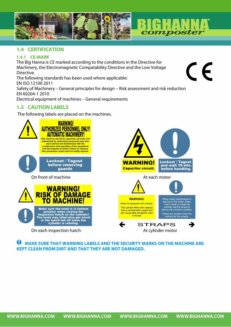
1.5 CAUTION LABELS The following labels are placed on the machines.
On front of machine At each motor
On each inspection hatch At cylinder motor
MAKE SURE THAT WARNING LABELS AND THE SECURITY MARKS ON THE MACHINE ARE KEPT CLEAN FROM DIRT AND THAT THEY ARE NOT DAMAGED.

1.6 FUNCTION, RANGE OF APPLICATION AND LIMITATIONS OF USE 1.6.1 FUNCTION The Composter is essentially a horizontally oriented cylinder with tight and stationary rear and front gables. The cylinder with its containing material is rotated and the material is turned over and ventilated periodically. Processed material is automatically fed out from the rear . Depending upon the amount and the composition of waste material a range of choices can be made regarding waiting time between turns, length of turning period and ventilation intensity . 1.6.2 STORAGE During the time from delivery to commissioning the machine shall be put under cover, been kept dry, at same a temperature above 10 degrees and well ventilated area – an area similar to a ware house. We recommend to store the unit of a maximum period of 2 months without connecting it to electricity if stored as above. Storage for longer periods, if the machine is taken from operation, must be indoors, frost free and in a dehumidified climate.
1.6.3 LIMITATIONS IN SIZE OF MATERIAL AND CAPACITY The Big Hanna Composter is designed for food waste, sawdust/pellets (together with food waste or water) only. Capacity vary depending on composition of food waste.
MODEL T480
Max capacity is 340 kg of food waste/day. The maximum particle size of non-soft food waste is Ø 12,7 cm. Max capacity of the inlet is 80 l. Max rotation of cylinder per 24h is 240 rotations.
1.6.4 DEFINITIONS (Source: www.ofmpub.epa.gov, www. eionet.europa.eu and www.wastestudies.com) Food waste 1: Uneaten food and food preparation wastes from residences and commercial establishments such as grocery stores, restaurants, and produce stands, institutional cafeterias and kitchens, and industrial sources like employee lunchrooms. Food waste 2: An unwanted raw or cooked food discarded during or after food preparation that is no longer fit for consumption or desirable i.e.: Spoiled cooked food Excess cooked food Vegetables & fruits peelings Beverage Undesirable raw food Meat scraps Vegetable waste: Waste, comprised mainly of vegetable matter, which is capable of being decomposed by micro-organisms. Organic waste: Waste containing carbon compounds; derived from animal and plant materials. Compostable waste: Waste consisting largely of biodegradable organic matter. Garden waste: Natural organic matter discarded from gardens and yards including leaves, grass clippings, pruning’s, brush and stumps. Animal waste: Discarded material from industries directly associated with the raising of animals, such as those wastes produced by livestock farming (manure, milk, etc.), meat production and animal testing (animal bodies, animal parts, feathers, etc.) and fur breeding (fur, blood, etc.). Agricultural waste: Unusable materials, liquid or solid, that result from agricultural practices, such as fertilizers, pesticides, crop residue (such as orchard prunings) and cattle manure.
Liquid waste: Fluid wastes, consisting of sewage and domestic wastewater, or processed water, or other liquids, produced by industrial activity, particularly by such industries as pulp and paper production, food processing, and the manufacture of chemicals. Hazardous waste: Any waste or combination of wastes with the potential to damage human health, living organisms or the environment. Hazardous wastes usually require special handling and disposal procedures which are regulated by national and international laws. Pesticides: A general term for chemical substances that are used to destroy or control insect or plant pests. Many pesticides are manufactured and do not occur naturally in the environment. Others are natural toxics that are extracted from plants and animals.
1.6.5 RANGE OF APPLICATION AND LIMITATIONS OF USE The Big Hanna Composter is designed for food waste, sawdust/pelletised sawdust (together with food waste or water) only. ‘Food waste’ as the first definition in 1.6.3 is possible to compost in the Big Hanna Composter if it is a proper mix, temperature, appropriate size (1-5 cm) and has a suitable moisture content. (Too much liquid seriously inhibits the biological process.) Most food waste from residences is suitable for composting as long as it is not contaminated by non food waste. In general all ‘food waste’ in the second definition in 1.6.3 can be composted with the exception of beverages. However also with this definition the mix, temperature, size and moisture content must be appropriate. The Big Hanna Composter is manufactured especially with food waste in mind. Not all organic or compostable wastes are suitable. Note that this composter is not designed for processing organic waste such as animal waste,
agricultural waste or liquid waste. If you want to use this machine for anything other than composting food waste within the limitations described above together with sawdust or pelletised sawdust ask the distributor’s advice or proceed at your own risk.
Garden waste can be put into the Big Hanna Composter only in smaller pieces (2-3 cm) and might not decompose properly depending on type. The compost process is a biological process, which must be treated with care in order to obtain a good result i.e. a good compost material that can be used as a fertiliser. The waste material that is put into the machine must be cleared from materials that may damage the equipment or disturb the biological process. Where the Big Hanna Composter is used the above limitations is rarely a problem and the sorting of food is done on another ‘level’. To help tenants and staff to sort the food waste see chapter ‘What to put in the composter’ and ‘4.2.2 What not to put in the composter’. This gives hands-on suggestions on practical sorting but is not a conclusive list of what is and is not suitable for composting. Detergents used in food preparation, cooking area, around the composter or where it may come in contact with the food waste should be organic and not bio accumulating. The information about obtaining temperatures and the biological process in this manual
constitutes no guarantee to do so by the manufacturer.

The quality of the produced compost, temperatures, moisture content etc is depending solely on the raw material (food waste and absorbent material) and on how the machine is operated. The manufacturer or distributor can therefore never guarantee the performance of any machine.
When the Big Hanna Composter is used to treat macerated food waste which has been dewatered the detergents that are used for cleaning the macerator/dewaterer may contaminate the food waste and should therefore be organic and not bio accumulating. When the food waste and sawdust / pelletised sawdust is turned and oxygen is supplied a natural occurring biological decomposing process is supported which produces compost within 8-12 weeks. There are numerous of excellent test results from compost which have been produced with the Big Hanna Composter. The test results prove that it is possible to produce excellent quality compost with the Big Hanna Composter but it does not constitute a guarantee: The biological process is not only dependant on the machine to function properly. The operation of the machine, i.e. adding sawdust or wood pellets with the food waste, getting the right C:N balance, settings of number of rotations and wait time is equally important. And even more important is the raw material fed into the machine i.e. the food waste. If the food waste is sterilized by using chemicals, pesticides, cold, heat or even ingredients that inhibit bacterial growth before being put into the machine, the biological process will not be functioning properly and the capacity of the machine will be much lower than expected. If the food waste is very wet this will also stop or slow down the biological process. The biological process also works much better with mixed food waste i.e. not only potatoes. A rule of thumb is that food waste that you would eat if it had not passed its expiration date is o.k. to feed to the machine. For example: FOOD FROM A FREEZER MUST BE THAWED BEFORE BEING FED TO THE COMPOSTER. A 25 KG BAG OF SALT WOULD EFFECTIVELY KILL THE BIOLOGICAL PROCESS. ADDING SAUCES OR OTHER LIQUIDS (ORGANIC OR NOT) WILL AFFECT OR KILL THE
BIOLOGICAL PROCESS. FOOD WASTE WHICH HAS BEEN SOAKED IN DETERGENT FLUID OR SPRAYED WITH
DETERGENT IN THE KITCHEN IF A BATCH OF FOOD IS DEEMED NOT FIT FOR HUMAN CONSUMPTION BECAUSE IT
CONTAINS TOO MUCH PESTICIDES OR CHEMICALS THIS SHOULD NOT BE PUT INTO THE COMPOSTER.
GARDEN WASTE THAT HAS BEEN TREATED WITH PESTICIDES WHICH ARE NOT BIODEGRADABLE SHOULD NOT BE PUT INTO THE COMPOSTER.
WASTE MATERIAL THAT CONTAINS LARGE AMOUNTS OF VINEGAR ESSENCE WILL KILL THE MICRO-ORGANISMS.
This list is non-conclusive and if you are having questions please contact your distributor.
1.6.6 SITE SPECIFIC REGULATIONS
ATTENTION! LOCAL OR SITE SPECIFIC REGULATIONS MAY APPLY TO ON SITE COMPOSTING. There are in some regions, countries or sites specific local regulations regarding food waste,
treating food waste on site, licence requirements for handling waste etc. The Big Hanna Composter must be used in accordance with local regulations. It is the sole responsibility of the owner of the Big Hanna Composter to have all required information about the local regulations that may apply for the use of this machine.
1.7 SAFE AND CORRECT USE In general terms the composter should be located to minimise transportation of the food waste and access by unauthorised people. Site specific activities like vehicles around the site, condition of flooring (slip-risk), manual handling of the food waste being collected etc must be considered by each employer at each site. Site-specific regulations include positioning and location of the composter which is the decision and responsibility of the customer. Some tips for your risk assessment for your site Positioning of the machinery Fencing when installing the machine in public areas Activities around the machine Lighting around the machine Transport Falls from height Slips and trips Manual handling Pest control
There is a possible risk for infection from collecting food waste that varies from site to site. The variation is due to different sources of food waste, collection routines, how old the collected food waste is (fungus and mould) and how contaminated it may be by glass or needles etc to mention a few variations. Also note in your own risk assessment if there is any risk for contamination of any other diseases. If there is a risk for needle stick injury all employees should be inoculated for relevant diseases, such as Hepatitis B. A sharps container should be kept on site and finds recorded. The personal protective equipment PPE recommended for Big Hanna Composter is a recommendation only not knowing the specific situation at the site; the decision has to be the employers. It is therefore the sole responsibility of the employer to implement a Safe System of Work at the site where Big Hanna is installed. The manufacturer is not aware of any specific rules or regulations that may apply at a specific site where the Big Hanna is installed. The Big Hanna is CE marked which means that it is produced according to the CE-mark standards in the European Union. All dangerous parts of this machinery are adequately guarded according to the CE-mark standards.

1.7.1 BIOHAZARD FROM COMPOSTING ACTIVITIES The Big Hanna Composter is in comparison with larger composting facilities a very small system. The exposure to fungus, spores etc is therefore minimal for a worker in both quantity and time spent with the biologically active material inside the cylinder. In larger facilities there are documented cases where workers full time working with composting material (i.e. working in tractors turning composting windrows) have contracted lung diseases including asthma. When working with the active material in the cylinder we recommend the same PPE as for bigger facilities. The inspection of the material inside the cylinder should not take more than a few minutes a week, the rest of the time the biological process is in a closed in-vessel system so there is no need for particle filter P3 breathing masks when being in the vicinity of the machine itself.
1.7.2 PATHOGENS IN THE FOOD WASTE Handled correctly and according to instructions the composting process eliminates pathogens that may be present in food waste, like salmonella, e-coli, etc. In order to prevent pathogens spreading from the food waste to other areas within the workplace (or to the finished compost) we recommend that protective clothing and gloves are used whilst feeding the food waste into the machine. These clothing/gloves should not be the same as the ones used when working with the compost
since there is a risk for re-contaminating the compost.
1.7.3 SLIPS AND TRIPS DUE TO SPILLAGE Accidental spillage of food waste around the machine can cause slips and trips. Employees must be instructed to take care to prevent spillage. If there is spillage this must be cleaned up immediately.
1.7.4 PEST CONTROL Big Hanna is an in-vessel system with a temperature of 50-60oC, which makes it uninhabitable for vermin. Stored food waste on site or accidental spillage of food waste around the machine can cause problems with vermin. If food waste is stored on site a separate risk assessment must be carried out. Employees must be instructed to take care to prevent spillage. If there is spillage this must be cleaned up immediately.
1.7.5 OPERATIONAL RISKS INVOLVING MACHINERY All moving parts are covered and tools needed/safety switch in place in order to come in contact with moving parts. All personnel must be informed that the Big Hanna Composter works on a timer function and therefore must be isolated at the main switch before any work is done on the composter.
1.7.6 OPERATIONAL TRAINING It is the sole responsibility of the owner of the machine that all staff receives the training that they require in order to safely operate the Big Hanna Composter. For the operational training there is a check-list in the ‘Installation Manual’. Some tasks may require specific qualifications due to site specific regulations.

1.8 SUPPLY DATA FOR ELECTRICITY Machines have optional Voltage and 1- or 3–phase option. See Machine specification delivered with machine for your machine’s electrical specification.
1.9 CAPACITY – EQUIPMENT – MEASUREMENTS – ELECTRICAL SUPPLY – ENERGY CONSUMPTION
Model T40 T60 T120 T240 T480 Capacity Kg/day 10-15 20-35 40-70 55-170 115-340 Kg/week 75-100 150-250 300-500 400-1200 800-2400 Tons/annum 4-5 8-13 16-26 21-62 41-124 Number of households 25-35 55-70 90-135 130-300 275-650 Equipment Temperature sensors - 3 3 3 3 Optional logging program - Optional hopper fed 40L inlet (in-conveyor) - - - Optional shredder - - - Optional bin lift - Inspection door(s) on hood - 1 2 2 2 Access door(s) in to cylinder 1 1 2 2 2 Visual digital display - Measurements Length (mm) 1 935 2 320 3 820 4 800 6 408 Width (mm) 880 1 080 1 080 1 400 2 000 Height (mm) 1 470 1 550 1 550 2 070 2 195 Volume cylinder (m³) 0,61 1,07 2 4 8 Weight empty (kg) 200 440 720 1200 4 500 Weight empty incl shredder/inlet(kg) - 490 770 - - Max weight full incl shredder/inlet (kg) 540 1100 1900 3500 10 100 Number of feet on machine 4 6 8 11 10 Connection to ventilation (mm) Ø110 Ø110 Ø110 Ø110 Ø110 Connection for drainage – T240, T480 and 40L hopper (mm) - Ø 75/
Ø110 Ø 75/ Ø110
Ø 75/ Ø110
Ø 75/ Ø110
Height inlet (mm) ca 1 000 ca 1 200 ca 1 200 ca 1 000 ca 1 000 Inlet measurements (mm) 285 x 295 285 x 295 285 x 295 490 x 590 490 x 590 Volume hopper fed inlet T240, T480 and 40L option - 40 l 40 l 80 l 80 l
Height under outlet (mm) 600 590 590 630 970

Model T40 T60 T120 T240 T480 Electrical supply*) Power supply 240 V 400 V 400 V 400V 400V Ampere 10 A 10 A 10 A 16 A 16 A Ampere incl 40L hopper fed inlet (inconveyor) - 10 A 10 A - - Ampere incl 40L hopper fed inlet incl shredder - 16 A 16 A - - Phases 1 3 3 3 3 Cables 3 5 5 5 5 Motor composter kW 0,12 0,37 0,37 1,1 0,55 Fan kW 0,04 0,04 0,04 0,04 0,37 In-conveyor kW (40L & 80Lhopper fed inlet) - 0,55 0,55 0,55 0,55 Shredder kW - 3 3 - - Heater kW 0,5 0,5 0,5 0,5 1 Total kW 0,66 0,91 0,91 2,19 2,47 Total kW incl 40L hopper fed inlet and shredder - 4,46 4,46 - -
Energy consumption **) Total kWh/day standard model 1,01 1 1 1,53 2,35 Total kWh/day incl 40L hopper fed inlet and shredder - 1,38 1,66 - -
*) Standard models. Other electrical supply can be specified at order (for example 1-phase). **) The electrical consumption is calculated for indoor installations. The heater is only used in cold temperatures and only when the temperature between the hood and the cylinder is lower than 5-10ºC.
Note! Machines can be ordered according to customer’s specification and pictures and description in this manual may not apply directly in these circumstances. Always consult ‘Machine specification’ for details on each specific machine.
Note! Susteco AB reserves the right to modify, at any time and without notice, any or all of its products’ features, designs, components and specifications.
1.10 USAGE OF COMPOST MATERIAL The composter ”produces” compost material, which is good for use as fertilizer in gardens etc. The compost material should if necessary be screened before it is used. There may be bones, plastic, bottle caps etc that should be removed before the material is used as a fertilizer.
1.10.1 SECONDARY TREATMENT OF THE COMPOST MATERIAL In most cases the compost material is stored between gardening seasons. Mostly the material is stored outdoors. A simple wooden frame around the material can be placed directly on the ground, no floor is necessary. The secondary treatment fulfil s the decomposing process and adds worms and micro flora to the compost material making it better as a fertilizer. Since the compost material often contains much nitrogen the compost material should be mixed 1 to 5 with ordinary soil for flowerpots. The mixed compost material can be put directly on to flowerbeds after the screening.
ATTENTION! THE COMPOST MUST BE STORED AND USED ACCORDING TO LOCAL REGULATIONS. PLEASE CONTACT THE AUTHORITY RESPONSIBLE FOR ENVIRONMENT IN CASE OF UNCERTAINTY.

1.11 PERFORMANCE DATA AND METHODS OF MEASUREMENT When using the composter there will be a reduction in volume of the waste material that is put into the composter by 80-90% and a reduction in weight by 70-80% (these figures may vary depending on the specific food waste fed in and does not constitute a performance guarantee). To measure performances of reduction in either bulk or weight simply measure incoming and outgoing material for a period of time. When doing this note that it takes 6-10 weeks for the material to be processed through the composter. The performance of the composter can also be measured by examining the quality of the compost material that comes out from the composter and the excess water that is collected from the condensation trap. The results from the measurements of the compost material depends 100% on the incoming material. In order to get good results the incoming material must be cleared from batteries, metal objects, plastic, etc. (some chemical substances and heavy metal that occurs in food will not decompose by the biological process.
1.11.1 MEASUREMENT ANALYSIS COMPOST MATERIAL The analysis data consists of the following parameters: Remember: What goes in - comes out!
Ph Magnesium, Mg Copper, Cu Residue on ignition Carbon tot, C Zinc, Zn
Nitrogen, N Mercury, Hg Carbon/Nitrogen quota C:N Ammonium, NH4-N Cadmium, Cd Conductivity
Nitrate NO3-N Lead, Pb E-coli Phosphorus, P Chrome, Cr Salmonella Potassium, K Nickel, Ni Clostridium perfringens Calcium, Ca

1.12 NOISE, SMELL, SEWAGE 1.12.1 NOISE The composter works very quietly. Fan runs constantly at a low airflow giving a noise level of 45-55 dB depending on the installation site. Motor rotating the cylinder at the set number of rotations and wait time gives almost the same noise level as the fan 45-65 dB depending on installation site. (Cylinder is normally rotating 1-3 minutes every 1-2 hours.) When the in conveyor (1-5 minutes per feed) the noise level is 45-65 dB depending on type of waste material. If there are disturbing or loud noises coming from the composter when the cylinder is rotating this
could mean that the engine and/or cylinder is overloaded. In this case the composter should be checked immediately.
1.12.2 SMELL A well managed compost where the decomposing process works well does not create a foul smell. In general the more meat and fish that is added to the composter the more smell the decomposing process produces. In order to minimize the smell the composter is equipped with a ventilation system that sucks out exhaust gas and smell from the composter. The ventilation installation must be adapted to each specific site existing conditions. We recommend to use a biofilter which reduces the smell by approx. 90%. See more detailed information in ‘Biofilter Manual’.
1.12.3 DRAIN TO SEWAGE Big Hanna models T480 is equipped with an inlet hopper drain. This drain can be connected to the sewage. Pipe connection is ø 110 mm. Local regulations for connection to sewage must be observed. Installation is done according to the instructions in the separate ‘Installation Manual’. NOTE! There must be a lid or water seal stopping the air from being sucked in to the hopper and
from there in to the cylinder by the fan see below pictures. If the pipe is connected this is very important since sewage gas may be drawn in to the machine if the water seal is no in place.

1.13 SAFETY INFORMATION 1.13.1 MASTER SWITCH
WARNING: THE ELECTRICAL EQUIPMENT SHOULD ONLY BE INSTALLED, ADJUSTED AND SERVICED BY QUALIFIED ELECTRICAL MAINTENANCE PERSONNEL WHO WERE TRAINED AND FAMILIARIZED WITH THE CONSTRUCTION AND OPERATION OF THE EQUIPMENT, THE HAZARDS INVOLVED AND ANY SITE SPECIFIC OR LOCAL REGULATIONS. FAILURE TO OBSERVE THIS PRECAUTION COULD RESULT IN BODILY INJURIES. There is a master switch on the electrical cabinet which is shaft mounted to the disconnector. This ensures that the main switch is always OFF before the electrical cabinet can be opened.
1.13.2 SAFETY EQUIPMENT
WARNING! THE CYLINDER ROTATES ON A TIMER FUNCTION. WHEN REMOVING THE BOLTED COVERS OR THE HOOD THE POWER SUPPLY MUST BE SWITCHED OFF AT THE MASTER SWITCH AND LOCKED.
The infeed hopper lid is equipped with a magnetic limit switch connected to a safety plc; when the lid is lifted the in conveyor stops. All four inspection doors on the hood are equipped with a magnetic limit switch connected to a safety plc; when the doors are opened all motors are stopped. There are two Emergency Stop buttons connected to a safety plc, one at the front and on at the back. When an emergency stop button is pressed all motors are stopped. The magnetic limit switch has one closing and one opening contact. The contacts are monitored by a safety plc. To avoid unauthorised operation of the switch it is only possible to actuate the switch with a coded magnet. Other magnets, screwdrivers and tools have no effect on the switch contacts. When the safety magnet gives a fixed green light the connection is ok. When there is a red light there is no connection.

1.13.3 WARNING – INFEED HOPPER LID When the infeed hopper lid is opened there is a small warning sign flashing on the touch screen. When the lid is closed this warning sign disappears. There is no need to reset the machine after opening and closing the infeed hopper lid.
1.13.4 INSPECTION DOOR(S) OPEN When any of the inspection door(s) on the hood is opened there is a small warning sign flashing on the touch screen. Close the inspection doors. When the doors are locked, reset the machine using the reset button.
1.13.5 EMERGENCY STOP When an emergency stop button is pressed there is a text appearing on the touch screen with an instruction that should be followed: ‘Warning! Emergency Stop active. Twist to release the Emergency Stop button and reset the machine on the reset button.’
1.13.6 SAFETY COMPONENTS Safety PLC and the electrical parts that are connected to the safety PLC such as emergency stop buttons, safety switches, frequency inverters and contactors are marked with ‘safety component’ in the Machine Specification. If a safety component is replaced on the machine the exact same brand and type must be used in order to keep the safety performance level of the machine.

1.14 SAFETY WARNINGS AND PROTECTION
WARNING: THIS MACHINE SHOULD BE OPERATED BY AUTHORISED PERSONNEL ONLY WHO WERE TRAINED AND FAMILIARIZED WITH THE CONSTRUCTION AND OPERATION OF THE EQUIPMENT AND THE HAZARDS INVOLVED. FAILURE TO OBSERVE THIS PRECAUTION COULD RESULT IN BODILY INJURIES.
THESE SAFETY INSTRUCTIONS AND PROTECTIONS MUST BE POSTED IN A VISIBLE LOCATION NEAR THE BIG HANNA COMPOSTER.
CHILDREN MAY NOT USE THIS MACHINE WITHOUT THE DIRECT SUPERVISION OF AN ADULT WHO WAS TRAINED AND FAMILIARIZED WITH THE CONSTRUCTION AND OPERATION OF THE EQUIPMENT AND THE HAZARDS INVOLVED.
WARNING! THIS MACHINE OPERATES ON A TIMER FUNCTION. THE POWER SUPPLY MUST BE SWITCHED OFF AT THE MASTER SWITCH AND THE MASTER SWITCH MUST BE LOCKED BEFORE REPAIRING OR SERVICING THE MACHINE AND REMOVING THE BOLTED COVERS.
WARNING: THE ELECTRICAL EQUIPMENT SHOULD ONLY BE INSTALLED, ADJUSTED AND SERVICED BY QUALIFIED ELECTRICAL MAINTENANCE PERSONNEL WHO WERE TRAINED AND FAMILIARIZED WITH THE CONSTRUCTION AND OPERATION OF THE EQUIPMENT, THE HAZARDS INVOLVED AND ALL SITE SPECIFIC OR LOCAL REGULATIONS. FAILURE TO OBSERVE THIS PRECAUTION COULD RESULT IN BODILY INJURIES.
WARNING: CAPACITOR CIRCUIT ON MOTORS.
WARNING – MOTOR FOR CYLINDER IS EQUIPPED WITH A BRAKE SECURING THE CYLINDER POSITION. THE CYLINDER WILL MOVE IF THE BRAKE IS DISCONNECTED.THE CYLINDER FILLED WITH MATERIAL HAS A CONSIDERABLE WEIGHT AND CAN CAUSE FATAL ACCIDENTS WHEN IT MOVES!
WARNING – CYLINDER IS SECURED WITH STRAPS DURING TRANSPORT. THE STRAPS MUST BE LOOSENED BEFORE ROTATING THE CYLINDER. THE STRAPS MUST ALWAYS BE LOOSE WHEN CYLINDER IS ROTATING!
WARNING! RISK OF DAMAGE TO MACHINE IF THE INSPECTION HATCHES ARE NOT PROPERLY CLOSED.
ALL TEST RUNNING WITH THE SECURITY MEASURES REMOVED MUST BE DONE ONLY BY AUTHORIZED PERSONNEL.
WARNING: PUTTING ONLY DRY LEAVES, CARDBOARD, PAPER OR OTHER COMPOSTABLE MATERIAL IN INFEED HOPPER WITH IN-CONVEYOR/SHREDDER MAY CAUSE A FIRE HAZARD. LIGHT DRY COMPOSTABLE MATERIALS SHOULD BE INSERTED THROUGH THE CYLINDER HATCH.
BIOHAZARD FROM HANDLING FOOD WASTE AND COMPOSTING. USE PROTECTIVE CLOTHING, GLOVES AND PARTICLE FILTER P3 BREATHING MASK.

CYLINDER NEEDS TO BE EMPTIED BEFORE DOING ANY WORK INSIDE THE CYLINDER! IF CYLINDER IS TO BE ENTERED INTO WITHOUT BEING COMPLETELY EMPTY, CARBON DIOXIDE LEVEL INSIDE MUST FIRST BE MEASURED WITH A CALIBRATED INSTRUMENT READING SAFE CARBON DIOXIDE LEVEL (BELOW 0.5%)! SAFETY MEASURES OF ENCLOSED AREA MUST STRICTLY BE APPLIED BEFORE ENTERING THE CYLINDER.
WARNING: SPILL OF FOOD WASTE MAY CAUSE SLIPS AND TRIPPING HAZARDS AND/OR ATTRACT VERMIN. KEEP ALL SURFACES AND PREMISES CLEAN.
WARNING! NEVER FILL THE CYLINDER WITH COMPOSTING MATERIAL ABOVE THE RECOMMENDED FILLING LEVEL OF 60-70% SINCE THIS CAN CAUSE SERIOUS DAMAGE TO THE COMPOSTER!
WARNING! LEAKAGE FROM THE FRONT GABLE MAY ACCUMULATE ON HEATER AND THIS CAN CAUSE A FIRE HAZARD UNDER THE HOOD. FOLLOW THE HEATER MAINTENANCE SCHEDULE AND METHODOLOGY TO AVOID FIRE HAZARD.
WARNING! THE COMPOSTER IS DESIGNED FOR FOOD WASTE AND SAWDUST OR PELLETISED SAWDUST ONLY. NEVER PUT METAL, OTHER INORGANIC OR ORGANIC MATERIAL OTHER THAN WHAT IS SPECIFIED IN THIS MANUAL IN TO THE COMPOSTER.
HAZARDOUS OR CONTAMINATED WASTE MAY UNDER NO CIRCUMSTANCES BE PUT INTO CYLINDER.
DO NOT STERILIZE THE FOOD WASTE BEFORE FEEDING IT INTO THE COMPOSTER AS THIS WILL SERIOUSLY INHIBIT THE BIOLOGICAL PROCESS.
THE COMPOSTER CAN ONLY BE MOVED WHEN IT IS EMPTY! NEVER ATTEMPT TO MOVE BIG HANNA COMPOSTER WHEN CYLINDER CONTAINS COMPOSTING MATERIAL.
WARNING! WHEN LIFTING: THE COMPOSTER IS HEAVIER AT THE FRONT! PROPER AND ADAPTED LIFTING MEASURES MUST BE TAKEN TO AVOID BODILY INJURIES OR BIG HANNA COMPOSTER DAMAGE.
ATTENTION! LOCAL OR SITE SPECIFIC REGULATIONS MAY APPLY TO ON SITE COMPOSTING.
ATTENTION! THE COMPOST MUST BE STORED AND USED ACCORDING TO LOCAL REGULATIONS. PLEASE CONTACT THE AUTHORITY RESPONSIBLE FOR ENVIRONMENT IN CASE OF UNCERTAINTY.
LOCKOUT / TAGOUT BEFORE REMOVING BOLTED COVERS.
CAPACITOR CIRCUIT ON ALL MOTORS. LOCKOUT / TAGOUT AND WAIT 10 MIN BEFORE HANDLING.
SECURE THE AREA AROUND TRANSMISSION FROM UNAUTHORIZED PERSONNEL WHILE TEST RUNNING WITH THE SECURITY MEASURES REMOVED.

WHEN DOING MAINTENANCE OR SERVICE ON THE MOTOR, CHAIN, CHAIN WHEEL OR INSIDE THE CYLINDER, USE THE STRAPS TO SECURE THE CYLINDER POSITION. STRAPS ARE LOCATED UNDER THE CARRIERS FOR THE WHEEL.
LOOSEN THE STRAPS HOLDING THE CYLINDER IN PLACE BEFORE ROTATING THE CYLINDER.
MAKE SURE THE KNOB IS IN BOTTOM POSITION WHEN CLOSING THE INSPECTION HATCH ON THE CYLINDER! THE KNOB MAY OTHERWISE GET STUCK OR THE HATCH FALL OFF WHEN THE CYLINDER IS ROTATING.
ALWAYS USE PROTECTIVE GLOVES WHEN WORKING WITH BIG HANNA COMPOSTER OR WHEN HANDLING THE MACHINE AND/OR THE COMPOST.
WHEN OPENING THE INSPECTION DOOR ON THE CYLINDER OR HANDLING COMPOST USE PROTECTIVE CLOTHING, GLOVES AND PARTICLE FILTER P3 BREATHING MASK.
WASH HANDS AFTER DOING WORK WITH THE BIG HANNA COMPOSTER.
MAKE SURE THE COMPOSTER IS EMPTYING MATERIAL. REMOVE ANY BLOCKAGE AT THE OUTLET.
ANY LEAKAGE FROM THE FRONT GABLE MUST BE CHECKED ONCE A MONTH. REMOVE ANY DUST FROM THE HEATER AND THE BOTTOM PLATE. NEVER USE STRONG DETERGENTS OR SOLVENT-BASED PRODUCTS TO CLEAN THE HEATER.
TAKE CARE TO PREVENT SPILL. IF THERE IS SPILL CLEAN UP IMMEDIATELY.
MAKE SURE THAT WARNING LABELS AND THE SECURITY MARKS ON THE MACHINE ARE KEPT CLEAN FROM DIRT AND THAT THEY ARE NOT DAMAGED.
WHEN MOVING OR TRANSPORTING THE COMPOSTER KEEP THE COMPOSTER AS CLOSE TO THE GROUND AS POSSIBLE.
IF THE COMPOSTER HAS BEEN MOVED CHECK THAT THE CARRYING STEEL FRAME IS WELL BALANCED.

1.15 INSTALLATION AND TRANSPORTATION 1.15.1 CLIMATE – PROTECTING THE MACHINE FROM THE ELEMENTS The machine can be installed indoors or outdoors but must be well protected from elements like rain, sunshine, sand etc. Temperature requirements when installed with a heater (optional): -20ºC up to 50ºC. Note that strong winds in combination with temperatures below zero increases the cooling effect and can make it hard for the heater to keep the temperature inbetween the hood and the cylinder above 10ºC. If the climate conditions with wind and cold are common we recommend installing the machine with walls protecting also from the wind. At installation sites where temperatures are below - 20 C degrees for more than 2-3 weeks in a row we recommend installing the composter in an indoor area keeping installation area at least about 0 degrees. Temperature requirements when installed without a heater (optional): 10ºC up to 50ºC. In areas where the temperature does not drop below 10ºC there is no need for a heater since the biological heat is generated naturally.
1.15.2 INSTALLATION See separate installation manual.
1.15.3 TRANSPORTATION OF THE COMPOSTER See separate installation manual.
1.16 NAMEPLATE ON MACHINE The nameplate is positioned on the front of the machine. The nameplate declares the number for one unique Big Hanna and is therefore very important in regards to traceability for spare parts.

2 ELECTRICITY
WARNING: THE ELECTRICAL EQUIPMENT SHOULD ONLY BE INSTALLED, ADJUSTED AND SERVICED BY QUALIFIED ELECTRICAL MAINTENANCE PERSONNEL WHO WERE TRAINED AND FAMILIARIZED WITH THE CONSTRUCTION AND OPERATION OF THE EQUIPMENT, THE HAZARDS INVOLVED AND ALL SITE SPECIFIC OR LOCAL REGULATIONS. FAILURE TO OBSERVE THIS PRECAUTION COULD RESULT IN BODILY INJURIES.
READ ALL SAFETY MEASURES IN CHAPTER 1.14
2.1 ELECTRICAL PARTS
Art no Item A Electrical cabinet 110205 Motor cylinder 110250 Motor inconveyor 110410 Motor fan 110131 Safety magnet contact 110141 Safety magnet contact key
Art no Item 110121 Inductive sensor ‘inspection door pos.’ 110125 Emergency stop button 110175 Heater 110231 Temperature sensors 110232 Temperature sensors
2.2 ‘MACHINE SPECIFICATION’ The Big Hanna Composter is delivered with a ‘Machine Specification’ which specifies the different electrical components .
2.3 ELECTRICAL WIRING DIAGRAM AND COMPONENT LIST The electrical wiring diagram is printed and attached to the ’Machine Specification’. One copy is placed inside the respective cabinets where it should always be available. Note! Machines can be ordered according to customer’s specification and pictures and description
in this manual may not apply directly in these circumstances. Always consult ‘Machine specification’ for details on each specific machine.
Note! Susteco AB reserves the right to modify, at any time and without notice, any or all of its products’ features, designs, components and specifications.

3 OPERATING INSTRUCTIONS 3.1 MAIN SWITCH, RESET BUTTON AND TOUCH SCREEN. The machine is operated from the touch screen which is placed on the door of the electrical cabinet. On the door of the electrical cabinet there is a main switch which must be locked out and tagged out when the bolted covers are removed and the machine is maintained or serviced. When the main switch on Big Hanna is turned on the fan starts automatically and the cylinder will start rotating after minimum 30 minutes on its automatic cycle. The Big Hanna’s biological process require 24/7 operation and should never be turned off at the main switch unless it its serviced, repaired or taken out of service. The blue reset button (not incl. on all models) on the electrical cabinet has three modes: Mode: Status: Dark blue/ Not lit up. No alarm. Power to all motors. Firm blue light. Alarm is active. No power to any motors. Pressing the button will not reset the
machine – fault must be located and the source of the alarm must be eliminated.
Flashing blue light. Alarm is not active but button needs to be pressed in order to reset the machine. No power to any motors.
1. Touch screen 2. Emergency stop button 3. Reset button 4. Main switch 5. USB Socket

3.2 START SCREEN The touch screen is placed on the outside of the electrical cabinet. From this screen you operate the composter choosing the different settings of number of turns, wait time etc. It also shows temperatures and gives the opportunity to download temperature log files. There are four different user levels: ‘Basic’, ‘Operator’,’ Tools’ and ‘Big Hanna’. The picture below shows the start screen for a T480 with a 7” screen. The start screen is the default screen and shows the machine number, the temperatures inside the cylinder and the temperature of the air going in to the cylinder (in blue just above/next to the fan). Optional sensors for measuring CO2, humidity and temperature in air from cylinder and moisture sensor for mass inside cylinder are also shown on the start screen when installed. There is also a shortcut to a help section on the biological process which can be accessed by simply pressing the waving ‘Big Hanna man’ without entering any pin code or password. (The help screens are only available for 7” screens.)
Note the machine number on the screen! When ordering spare parts/service etc., always provide
this number. Note! The program will automatically return to the start screen after 20 minutes of inactivity on
any other screen!

3.3 NAVIGATING BETWEEN DIFFERENT SCREENS Press the different symbols to navigate between the different screens.
Press the numeric key pad, enter pin code and access ‘basic’ level (see below).
Press the ‘Big Hanna Home,’ enter password and access ‘Operator,’ ‘Tools’ and ‘Big Hanna.’ When Big Hanna is delivered with a RFID reader (optional) the
swipe of a RFID-card will replace entering the PIN code or logging in to the touch screen depending on the program for the specific machine. The custom made logic for a machine can be found in the machine specification.
At the bottom of most screens, there are navigation arrows taking you to the next screen (arrow in right hand corner) or to the previous screen (arrow in left hand corner). Note that the arrows only navigate between the different screens within that level. The red ‘X’ will always take you back to the start screen.
The different menus are divided into user levels and are coloured differently: Orange: Help section Green: ‘Operator’ (Choice of number of rotations, wait time, downloading data etc.) Blue: ‘Tools’ (Choice for language, setting of machine number and weighing option.) Grey: ‘Big Hanna’ (Factory settings – only used by the manufacturer / distributor.) [Yellow: ‘Alarm’ (This is not a ‘level’ as such but all alarm screens have a yellow layout.)]

3.4 HELP SECTION
The help section is always available by pressing the waving ‘Big Hanna man’ without entering any pin code or password.
The ’Big Hanna man’ gives information about: Daily check-up Weekly check-up Good Biological process Hot zone troubleshooting
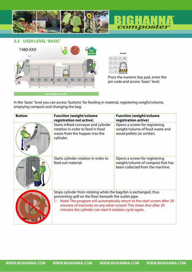
3.5 USER LEVEL ‘BASIC’
In the ‘basic’ level you can access ‘buttons’ for feeding in material, registering weight/volume, emptying compost and changing the bag:
Button Function (weight/volume registration not active)
Function (weight/volume registration active)
Starts infeed conveyor and cylinder rotation in order to feed in food waste from the hopper into the cylinder.
Opens a screen for registering weight/volume of food waste and wood pellets (or similar).
Starts cylinder rotation in order to feed out material.
Opens a screen for registering weight/volume of compost that has been collected from the machine.
Stops cylinder from rotating while the bag/bin is exchanged, thus preventing spill on the floor beneath the outlet pipe. Note! The program will automatically return to the start screen after 20
minutes of inactivity on any other screen! This mean that after 20 minutes the cylinder can start it rotation cycle again.
Press the numeric key pad, enter the pin code and access ‘basic’ level.

3.6 PREPARATION OF FOOD WASTE FOR COMPOSTING It is very important to sort the food waste from other waste before putting it into the composter
(also see 1.6.4 and 4.2.2 on what the limitations of this machine is). When having an in-conveyor and shredder installed this is even more important since feeding the in-conveyor and shredder with metal objects etc may cause serious damage to the machinery.
3.6.1 CUT THE WASTE MATERIAL It is important that all waste material that is put into the composter is cut in small pieces (2-3 cm) giving the micro-organisms a larger surface on the waste material to work on. By cutting the material the quality of the outgoing compost material will be improved. Citrus fruits have to be cut before being put into the composter because these fruits are treated with biocides on the peel and which stop the micro-organisms to getting the decomposing process started. If the citrus fruits are put in without being cut they will eventually come out whole and will have to be cleared from the other composted material. CUT CITRUS FRUITS CUT POTATOES AND CUT PLANTS AND
ROOT VEGETABLES GARDEN REFUSE
The infeed hopper’s volume is 80 litres. The maximum particle size of non-soft food waste is ∅ 12,7 cm.
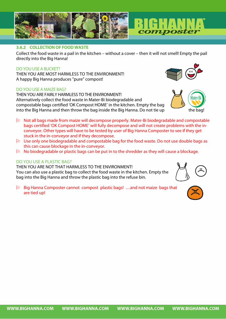
3.6.2 COLLECTION OF FOOD WASTE Collect the food waste in a pail in the kitchen – without a cover – then it will not smell! Empty the pail directly into the Big Hanna! DO YOU USE A BUCKET? THEN YOU ARE MOST HARMLESS TO THE ENVIRONMENT! A happy Big Hanna produces ”pure” compost! DO YOU USE A MAIZE BAG? THEN YOU ARE FAIRLY HARMLESS TO THE ENVIRONMENT! Alternatively collect the food waste in Mater-Bi biodegradable and compostable bags certified ‘OK Compost HOME’ in the kitchen. Empty the bag into the Big Hanna and then throw the bag inside the Big Hanna. Do not tie up the bag! Not all bags made from maize will decompose properly. Mater-Bi biodegradable and compostable
bags certified ‘OK Compost HOME’ will fully decompose and will not create problems with the in-conveyor. Other types will have to be tested by user of Big Hanna Composter to see if they get stuck in the in-conveyor and if they decompose.
Use only one biodegradable and compostable bag for the food waste. Do not use double bags as this can cause blockage in the in-conveyor.
No biodegradable or plastic bags can be put in to the shredder as they will cause a blockage. DO YOU USE A PLASTIC BAG? THEN YOU ARE NOT THAT HARMLESS TO THE ENVIRONMENT! You can also use a plastic bag to collect the food waste in the kitchen. Empty the bag into the Big Hanna and throw the plastic bag into the refuse bin. Big Hanna Composter cannot compost plastic bags! …and not maize bags that
are tied up!
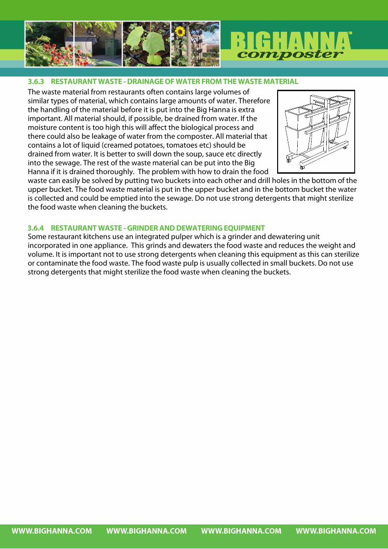
3.6.3 RESTAURANT WASTE - DRAINAGE OF WATER FROM THE WASTE MATERIAL The waste material from restaurants often contains large volumes of similar types of material, which contains large amounts of water. Therefore the handling of the material before it is put into the Big Hanna is extra important. All material should, if possible, be drained from water. If the moisture content is too high this will affect the biological process and there could also be leakage of water from the composter. All material that contains a lot of liquid (creamed potatoes, tomatoes etc) should be drained from water. It is better to swill down the soup, sauce etc directly into the sewage. The rest of the waste material can be put into the Big Hanna if it is drained thoroughly. The problem with how to drain the food waste can easily be solved by putting two buckets into each other and drill holes in the bottom of the upper bucket. The food waste material is put in the upper bucket and in the bottom bucket the water is collected and could be emptied into the sewage. Do not use strong detergents that might sterilize the food waste when cleaning the buckets.
3.6.4 RESTAURANT WASTE - GRINDER AND DEWATERING EQUIPMENT Some restaurant kitchens use an integrated pulper which is a grinder and dewatering unit incorporated in one appliance. This grinds and dewaters the food waste and reduces the weight and volume. It is important not to use strong detergents when cleaning this equipment as this can sterilize or contaminate the food waste. The food waste pulp is usually collected in small buckets. Do not use strong detergents that might sterilize the food waste when cleaning the buckets.
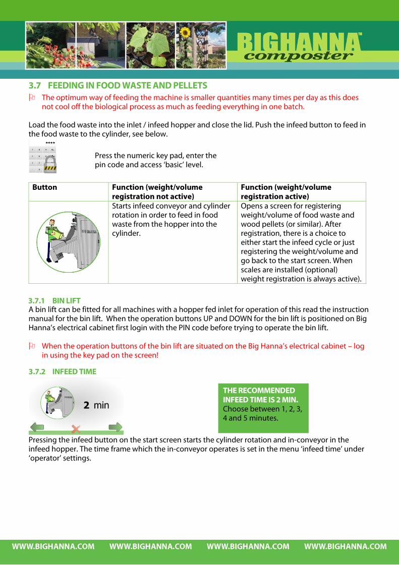
3.7 FEEDING IN FOOD WASTE AND PELLETS The optimum way of feeding the machine is smaller quantities many times per day as this does
not cool off the biological process as much as feeding everything in one batch. Load the food waste into the inlet / infeed hopper and close the lid. Push the infeed button to feed in the food waste to the cylinder, see below.
Button Function (weight/volume registration not active)
Function (weight/volume registration active)
Starts infeed conveyor and cylinder rotation in order to feed in food waste from the hopper into the cylinder.
Opens a screen for registering weight/volume of food waste and wood pellets (or similar). After registration, there is a choice to either start the infeed cycle or just registering the weight/volume and go back to the start screen. When scales are installed (optional) weight registration is always active).
3.7.1 BIN LIFT A bin lift can be fitted for all machines with a hopper fed inlet for operation of this read the instruction manual for the bin lift. When the operation buttons UP and DOWN for the bin lift is positioned on Big Hanna’s electrical cabinet first login with the PIN code before trying to operate the bin lift. When the operation buttons of the bin lift are situated on the Big Hanna’s electrical cabinet – log
in using the key pad on the screen!
3.7.2 INFEED TIME
Pressing the infeed button on the start screen starts the cylinder rotation and in-conveyor in the infeed hopper. The time frame which the in-conveyor operates is set in the menu ‘infeed time’ under ‘operator’ settings.
THE RECOMMENDED INFEED TIME IS 2 MIN. Choose between 1, 2, 3, 4 and 5 minutes.
Press the numeric key pad, enter the pin code and access ‘basic’ level.

3.7.3 MANUAL REGISTRATION OF WEIGHT / VOLUME OF FOOD WASTE AND PELLETS If registration of weight/volume is activated, the following screen will appear after pressing the infeed button (see above). Press the food waste symbol and enter the weight/volume of food waste that is fed in on the numeric key pad that appears. Confirm with enter.
Press the pellets symbol and enter the weight/volume of pellets that is fed in on the numeric key pad that appears. Confirm with enter. Choose action:
Register weight/volume, feed in material (infeed cycle starts) and rotate the cylinder.
Register weight/volume without feeding in material or rotating the cylinder.
Feed in material (infeed cycle start) and rotate the cylinder without registering weight/volume.
Go back to start screen without registering weight/volume, feed in material or rotating cylinder.
The registration of weight/volume is chosen in ‘tools’ menu. The registered values are visible when logging in to settings and the data can be downloaded, see below.

3.7.4 REGISTRATION OF WEIGHT OF FOOD WASTE, PELLETS AND COMPOST WITH SCALES CONNECTED TO THE TOUCH PANEL (OPTIONAL)
When scales (optional) are installed weight registration is always active and the following screen will appear after pressing the infeed button (see above). Net weight is presented to the left. Press the food waste symbol, the pellets symbol or the compost symbol depending on what kind of
material is on the scale. (Compost is sometimes fed in to support the biological process.) The weight can also be entered manually by clicking on the numbers of food waste, pellets and compost respectively. When the number that you want to register is visible to the right of the food waste, pellets and compost choose action:
Register weight/volume, feed in material (infeed cycle starts) and rotate the cylinder.
Register weight/volume without feeding in material or rotating the cylinder.
Feed in material (infeed cycle start) and rotate the cylinder without registering weight/volume.
Go back to start screen without registering weight/volume, feed in material or rotating cylinder.
Tare weight is also presented on the screen. When using wheelie bins or buckets for the food waste use an empty bin or bucket when entering the tare weight. If the tare function is not working properly use the zero command which is available in tools.
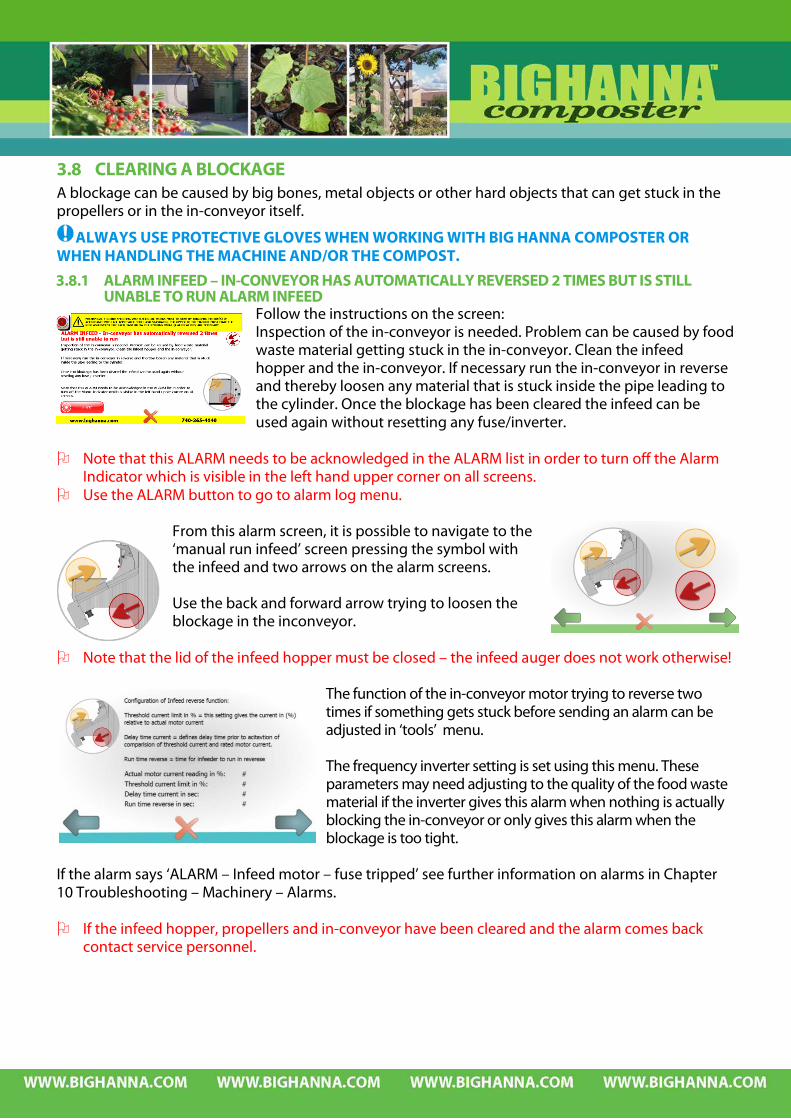
3.8 CLEARING A BLOCKAGE A blockage can be caused by big bones, metal objects or other hard objects that can get stuck in the propellers or in the in-conveyor itself.
ALWAYS USE PROTECTIVE GLOVES WHEN WORKING WITH BIG HANNA COMPOSTER OR WHEN HANDLING THE MACHINE AND/OR THE COMPOST.
3.8.1 ALARM INFEED – IN-CONVEYOR HAS AUTOMATICALLY REVERSED 2 TIMES BUT IS STILL UNABLE TO RUN ALARM INFEED
Follow the instructions on the screen: Inspection of the in-conveyor is needed. Problem can be caused by food waste material getting stuck in the in-conveyor. Clean the infeed hopper and the in-conveyor. If necessary run the in-conveyor in reverse and thereby loosen any material that is stuck inside the pipe leading to the cylinder. Once the blockage has been cleared the infeed can be used again without resetting any fuse/inverter.
Note that this ALARM needs to be acknowledged in the ALARM list in order to turn off the Alarm
Indicator which is visible in the left hand upper corner on all screens. Use the ALARM button to go to alarm log menu.
From this alarm screen, it is possible to navigate to the ‘manual run infeed’ screen pressing the symbol with the infeed and two arrows on the alarm screens. Use the back and forward arrow trying to loosen the blockage in the inconveyor.
Note that the lid of the infeed hopper must be closed – the infeed auger does not work otherwise!
The function of the in-conveyor motor trying to reverse two times if something gets stuck before sending an alarm can be adjusted in ‘tools’ menu. The frequency inverter setting is set using this menu. These parameters may need adjusting to the quality of the food waste material if the inverter gives this alarm when nothing is actually blocking the in-conveyor or only gives this alarm when the blockage is too tight.
If the alarm says ‘ALARM – Infeed motor – fuse tripped’ see further information on alarms in Chapter 10 Troubleshooting – Machinery – Alarms. If the infeed hopper, propellers and in-conveyor have been cleared and the alarm comes back
contact service personnel.
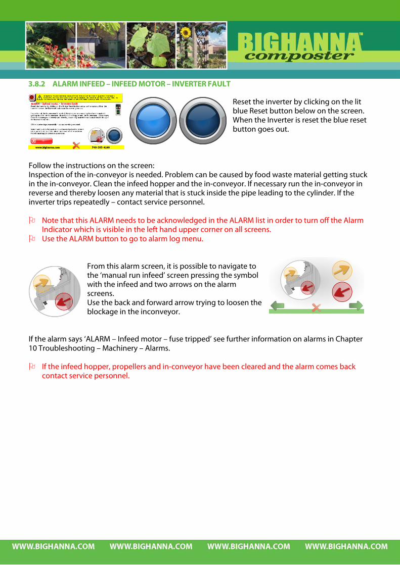
3.8.2 ALARM INFEED – INFEED MOTOR – INVERTER FAULT Reset the inverter by clicking on the lit blue Reset button below on the screen. When the Inverter is reset the blue reset button goes out.
Follow the instructions on the screen: Inspection of the in-conveyor is needed. Problem can be caused by food waste material getting stuck in the in-conveyor. Clean the infeed hopper and the in-conveyor. If necessary run the in-conveyor in reverse and thereby loosen any material that is stuck inside the pipe leading to the cylinder. If the inverter trips repeatedly – contact service personnel. Note that this ALARM needs to be acknowledged in the ALARM list in order to turn off the Alarm
Indicator which is visible in the left hand upper corner on all screens. Use the ALARM button to go to alarm log menu.
From this alarm screen, it is possible to navigate to the ‘manual run infeed’ screen pressing the symbol with the infeed and two arrows on the alarm screens. Use the back and forward arrow trying to loosen the blockage in the inconveyor.
If the alarm says ‘ALARM – Infeed motor – fuse tripped’ see further information on alarms in Chapter 10 Troubleshooting – Machinery – Alarms. If the infeed hopper, propellers and in-conveyor have been cleared and the alarm comes back
contact service personnel.
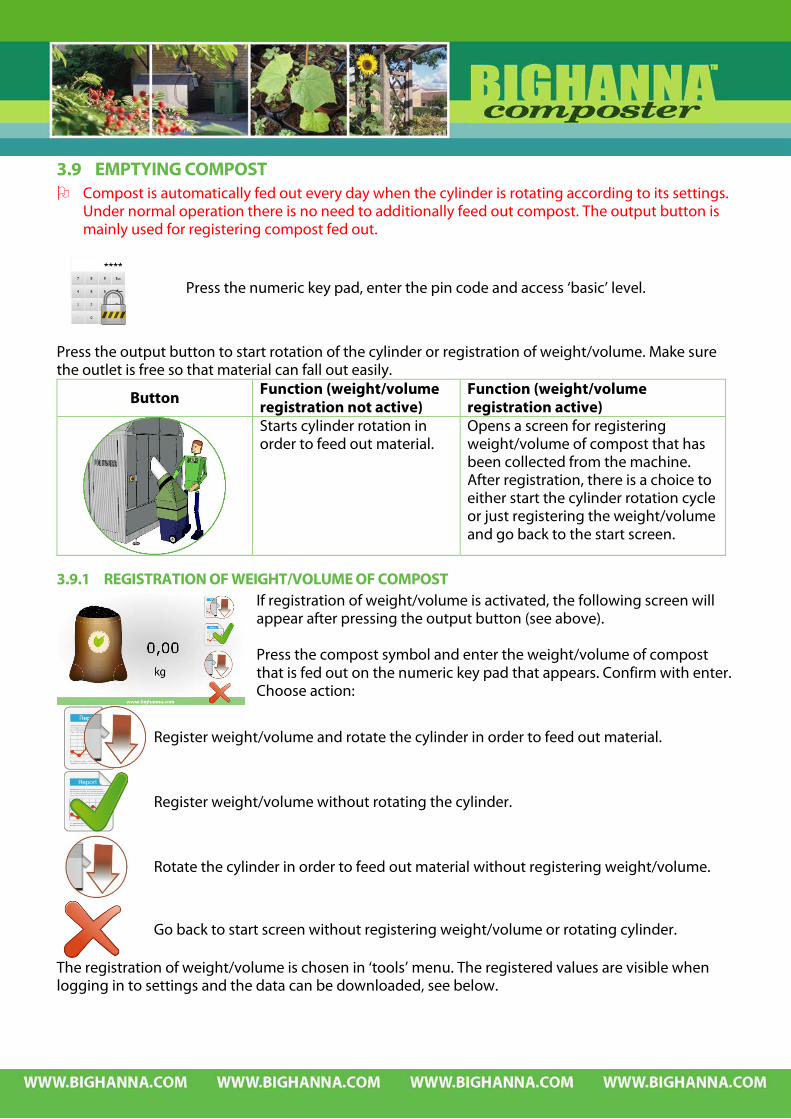
3.9 EMPTYING COMPOST Compost is automatically fed out every day when the cylinder is rotating according to its settings.
Under normal operation there is no need to additionally feed out compost. The output button is mainly used for registering compost fed out.
Press the output button to start rotation of the cylinder or registration of weight/volume. Make sure the outlet is free so that material can fall out easily.
Button Function (weight/volume registration not active)
Function (weight/volume registration active)
Starts cylinder rotation in order to feed out material.
Opens a screen for registering weight/volume of compost that has been collected from the machine. After registration, there is a choice to either start the cylinder rotation cycle or just registering the weight/volume and go back to the start screen.
3.9.1 REGISTRATION OF WEIGHT/VOLUME OF COMPOST If registration of weight/volume is activated, the following screen will appear after pressing the output button (see above). Press the compost symbol and enter the weight/volume of compost that is fed out on the numeric key pad that appears. Confirm with enter. Choose action:
Register weight/volume and rotate the cylinder in order to feed out material.
Register weight/volume without rotating the cylinder.
Rotate the cylinder in order to feed out material without registering weight/volume.
Go back to start screen without registering weight/volume or rotating cylinder.
The registration of weight/volume is chosen in ‘tools’ menu. The registered values are visible when logging in to settings and the data can be downloaded, see below.
Press the numeric key pad, enter the pin code and access ‘basic’ level.

3.10 EMPTY BAG OR BIN OF COMPOST
This button stops the cylinder from rotating while the bag/bin is exchanged preventing spill on the floor beneath the outlet pipe.
Follow the instructions on the screen: Remove the outlet cover (if appl.) Remove the bin/bag Clear the passage inside the outlet pipe if necessary Put an empty bin/bag in position Put outlet cover back in position (if appl.) Make sure that the bag is tight on the outlet or that the outlet cover is tight on the outlet and bin When you are ready click on the red ‘X’ to go back to the start screen
The red exit ‘X’ symbol must be pressed in order to return to the start screen so that the cylinder can rotate according to settings again. Note! The program will automatically return to the start screen after 20 minutes of inactivity on any other screen! This mean that after 20 minutes the cylinder can start it rotation cycle again. Note! The function of stopping the cylinder from rotating while the bag/bin
is exchanged is in no way connected to the safety system.
LOCKOUT / TAGOUT BEFORE REMOVING BOLTED COVERS.
Press the numeric key pad, enter the pin code and access ‘basic’ level.
3.11 LOGIN
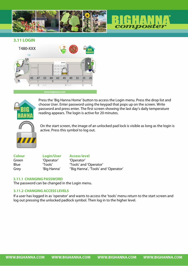
Press the ‘Big Hanna Home’ button to access the Login menu. Press the drop list and choose User. Enter password using the keypad that pops up on the screen. Write password and press enter. The first screen showing the last day’s daily temperature reading appears. The login is active for 20 minutes.
On the start screen, the image of an unlocked pad lock is visible as long as the login is active. Press this symbol to log out.
Colour Login/User Access level Green ‘Operator’ ‘Operator’ Blue ‘Tools’ ‘Tools’ and ‘Operator’ Grey ‘Big Hanna’ ‘’Big Hanna’, ‘Tools’ and ‘Operator’
3.11.1 CHANGING PASSWORD The password can be changed in the Login menu.
3.11.2 CHANGING ACCESS LEVELS If a user has logged in as ‘operator’ and wants to access the ‘tools’ menu return to the start screen and log out pressing the unlocked padlock symbol. Then log in to the higher level.

3.11.3 USER LEVEL ‘OPERATOR’ The following screens are available on user level ‘operator’:
Daily temperatures
Temperature graph
Food waste/compost log
Number of rotations
Wait time
Infeed time
Fan
Heater (Optional)
Alarm log
Log file temperatures
Log file Food waste/compost
Log file Alarms
Energy consumption (Optional)
Manual run infeed
Manual rotation cylinder
Tools and Factory settings
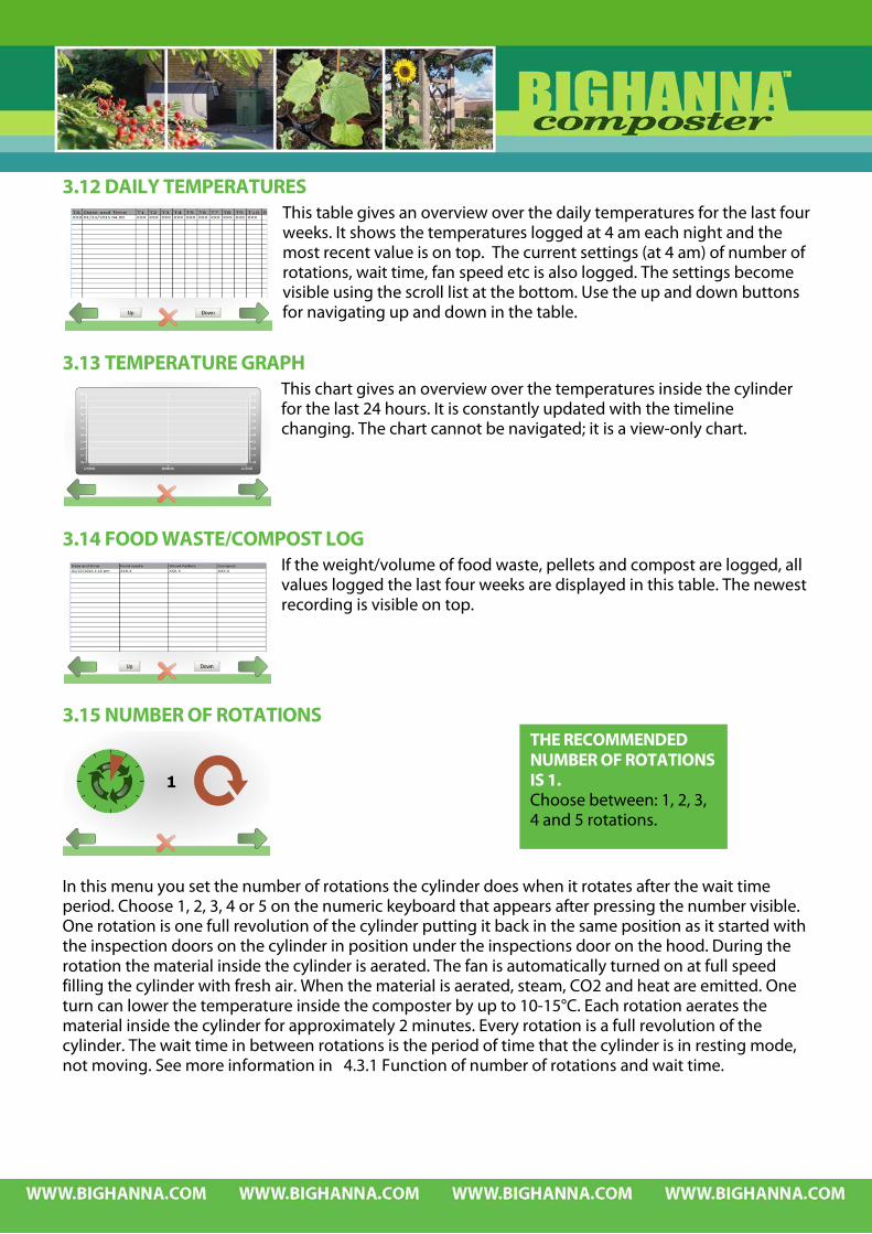
3.12 DAILY TEMPERATURES This table gives an overview over the daily temperatures for the last four weeks. It shows the temperatures logged at 4 am each night and the most recent value is on top. The current settings (at 4 am) of number of rotations, wait time, fan speed etc is also logged. The settings become visible using the scroll list at the bottom. Use the up and down buttons for navigating up and down in the table.
3.13 TEMPERATURE GRAPH This chart gives an overview over the temperatures inside the cylinder for the last 24 hours. It is constantly updated with the timeline changing. The chart cannot be navigated; it is a view-only chart.
3.14 FOOD WASTE/COMPOST LOG If the weight/volume of food waste, pellets and compost are logged, all values logged the last four weeks are displayed in this table. The newest recording is visible on top.
3.15 NUMBER OF ROTATIONS
In this menu you set the number of rotations the cylinder does when it rotates after the wait time period. Choose 1, 2, 3, 4 or 5 on the numeric keyboard that appears after pressing the number visible. One rotation is one full revolution of the cylinder putting it back in the same position as it started with the inspection doors on the cylinder in position under the inspections door on the hood. During the rotation the material inside the cylinder is aerated. The fan is automatically turned on at full speed filling the cylinder with fresh air. When the material is aerated, steam, CO2 and heat are emitted. One turn can lower the temperature inside the composter by up to 10-15°C. Each rotation aerates the material inside the cylinder for approximately 2 minutes. Every rotation is a full revolution of the cylinder. The wait time in between rotations is the period of time that the cylinder is in resting mode, not moving. See more information in 4.3.1 Function of number of rotations and wait time.
THE RECOMMENDED NUMBER OF ROTATIONS IS 1. Choose between: 1, 2, 3, 4 and 5 rotations.
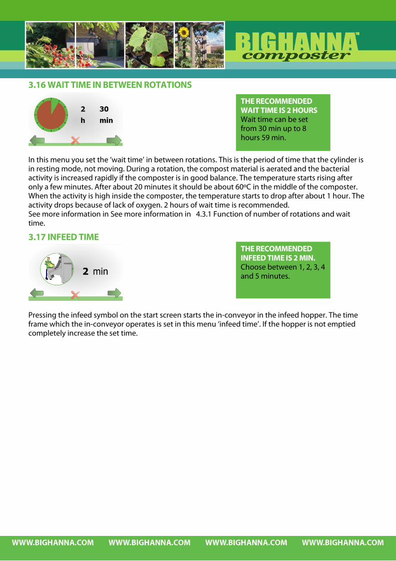
3.16 WAIT TIME IN BETWEEN ROTATIONS
In this menu you set the ‘wait time’ in between rotations. This is the period of time that the cylinder is in resting mode, not moving. During a rotation, the compost material is aerated and the bacterial activity is increased rapidly if the composter is in good balance. The temperature starts rising after only a few minutes. After about 20 minutes it should be about 60ºC in the middle of the composter. When the activity is high inside the composter, the temperature starts to drop after about 1 hour. The activity drops because of lack of oxygen. 2 hours of wait time is recommended. See more information in See more information in 4.3.1 Function of number of rotations and wait time.
3.17 INFEED TIME
Pressing the infeed symbol on the start screen starts the in-conveyor in the infeed hopper. The time frame which the in-conveyor operates is set in this menu ‘infeed time’. If the hopper is not emptied completely increase the set time.
THE RECOMMENDED WAIT TIME IS 2 HOURS Wait time can be set from 30 min up to 8 hours 59 min.
THE RECOMMENDED INFEED TIME IS 2 MIN. Choose between 1, 2, 3, 4 and 5 minutes.
3.18 FAN REGULATION
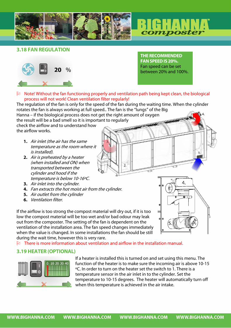
Note! Without the fan functioning properly and ventilation path being kept clean, the biological process will not work! Clean ventilation filter regularly!
The regulation of the fan is only for the speed of the fan during the waiting time. When the cylinder rotates the fan is always working at full speed.. The fan is the “lungs” of the Big Hanna – if the biological process does not get the right amount of oxygen the result will be a bad smell so it is important to regularly check the airflow and to understand how the airflow works.
1. Air inlet (the air has the same temperature as the room where it is installed).
2. Air is preheated by a heater (when installed and ON) when transported between the cylinder and hood if the temperature is below 10-16ºC.
3. Air inlet into the cylinder. 4. Fan extracts the hot moist air from the cylinder. 5. Air outlet from the cylinder 6. Ventilation filter.
If the airflow is too strong the compost material will dry out, if it is too low the compost material will be too wet and/or bad odour may leak out from the composter. The setting of the fan is dependent on the ventilation of the installation area. The fan speed changes immediately when the value is changed. In some installations the fan should be still during the wait time, however this is very rare. There is more information about ventilation and airflow in the installation manual.
3.19 HEATER (OPTIONAL) If a heater is installed this is turned on and set using this menu. The function of the heater is to make sure the incoming air is above 10-15 ºC. In order to turn on the heater set the switch to 1. There is a temperature sensor in the air inlet in to the cylinder. Set the temperature to 10-15 degrees. The heater will automatically turn off when this temperature is achieved in the air intake.
THE RECOMMENDED FAN SPEED IS 20%. Fan speed can be set between 20% and 100%.
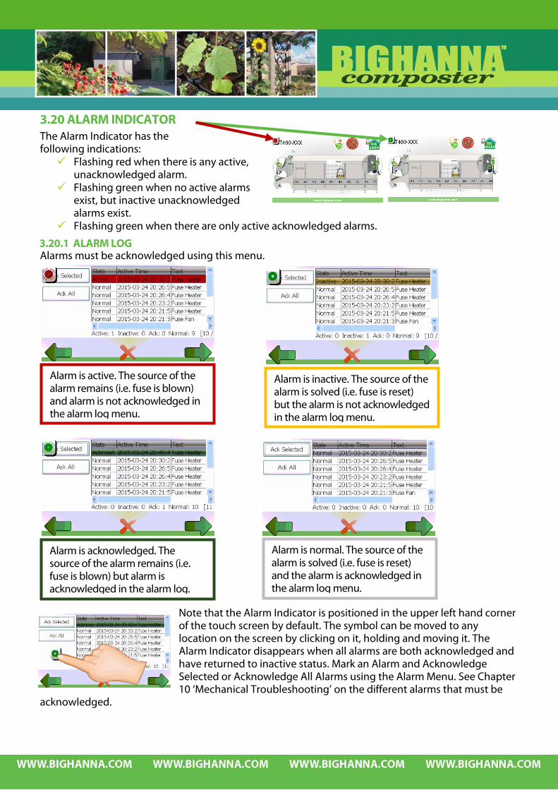
3.20 ALARM INDICATOR The Alarm Indicator has the following indications: Flashing red when there is any active,
unacknowledged alarm. Flashing green when no active alarms
exist, but inactive unacknowledged alarms exist.
Flashing green when there are only active acknowledged alarms.
3.20.1 ALARM LOG Alarms must be acknowledged using this menu.
Note that the Alarm Indicator is positioned in the upper left hand corner of the touch screen by default. The symbol can be moved to any location on the screen by clicking on it, holding and moving it. The Alarm Indicator disappears when all alarms are both acknowledged and have returned to inactive status. Mark an Alarm and Acknowledge Selected or Acknowledge All Alarms using the Alarm Menu. See Chapter 10 ‘Mechanical Troubleshooting’ on the different alarms that must be
acknowledged.
Alarm is active. The source of the alarm remains (i.e. fuse is blown) and alarm is not acknowledged in the alarm log menu.
Alarm is inactive. The source of the alarm is solved (i.e. fuse is reset) but the alarm is not acknowledged in the alarm log menu.
Alarm is acknowledged. The source of the alarm remains (i.e. fuse is blown) but alarm is acknowledged in the alarm log.
Alarm is normal. The source of the alarm is solved (i.e. fuse is reset) and the alarm is acknowledged in the alarm log menu.

3.21 SAVING AND DOWNLOADING DATA FROM THE TOUCH SCREEN There are three different screens with three different log files available. Choose the log file you want to download by choosing screen. Choose downloading to USB key, to SD Card or to the hard drive of the touch screen. See more information on the different ways of downloading below. Data is saved in .csv format which can be imported to Excel – see below.
Log file temperatures Log file Food waste/compost Log file Alarms
3.21.1 LOG FILE TEMPERATURES The touch screen plc (programmable logic controller) saves the current temperatures and settings into a log file every hour. The following parameters are saved every hour: Date and Time, T1, T2, T3, T4, T5, T6, T7, T8, T9, T10, Air Temperature, Rotations, Wait time h, Wait time min, Fan on/off, Fan speed, Heater on/off, Heater setting and kWh. There are two available log files. One with all logged parameters (every hour) since start-up “∞” and one showing only the last 100 days / one logged item per day symbolized with a calendar. The latter gives an overview of the latest development of the biological process.
3.21.2 LOG FILE FOOD WASTE / COMPOST If the function of registering weight/volume is ON, all values that are entered are saved by the plc (programmable logic controller) in to a log file the moment they are entered on the touch screen. The following parameters are saved: Date and Time, Food Waste, Pellets and Compost.
3.21.3 LOG FILE ALARMS The touch screens plc (programmable logic controller) saves the following alarms in a log file when they occur together with date and time: Emergency Stop, Infeed motor – Infeed has tried to reverse two times but is still unable to run, Infeed motor – fuse tripped, Infeed motor – inverter fault, Cylinder motor – fuse tripped, Cylinder motor – inverter fault, Cylinder is not rotating according to settings, Fan motor – fuse tripped, Fan motor – inverter fault, Heater – fuse tripped.

3.22 DOWNLOADING DATA TO USB AND SD CARD
The USB socket and SD card slot can be found on the inside of the electrical cabinet on the back of the touch panel. In some cases the USB socket or SD card slot is mounted on the outside of the door for convenience. Choose the log file you want to download by choosing screen.
Log file temperatures Log file Food waste/compost Log file Alarms In order to avoid having to open the door to the electrical cabinet (and thereby switching of electricity) twice, we recommend using two USB sticks/SD cards. One USB stick/SD card should always be in the touch panel. Click on the USB symbol for downloading to a USB stick and the SD card symbol for downloading to a SD card. There will be a short message on the screen ‘downloading data’. The log file is now saved. If you wish to download all three log files, repeat the above on all three screens before removing the USB stick/SD card from the touch panel. The download creates the following file structure:
The log file with the alarms is stored in the folder ‘Alarm Server’ and the other two log files are stored in ‘Data Loggers.’ Open the electrical cabinet and exchange USB stick/SD card, alternatively remove it from the socket/slot on the door.
DatabaseExport Alarm Server
Data Loggers
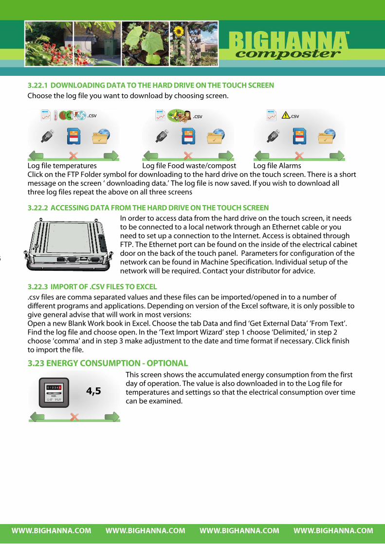
3.22.1 DOWNLOADING DATA TO THE HARD DRIVE ON THE TOUCH SCREEN Choose the log file you want to download by choosing screen.
Log file temperatures Log file Food waste/compost Log file Alarms Click on the FTP Folder symbol for downloading to the hard drive on the touch screen. There is a short message on the screen ‘ downloading data.’ The log file is now saved. If you wish to download all three log files repeat the above on all three screens
3.22.2 ACCESSING DATA FROM THE HARD DRIVE ON THE TOUCH SCREEN In order to access data from the hard drive on the touch screen, it needs to be connected to a local network through an Ethernet cable or you need to set up a connection to the Internet. Access is obtained through FTP. The Ethernet port can be found on the inside of the electrical cabinet door on the back of the touch panel. Parameters for configuration of the network can be found in Machine Specification. Individual setup of the network will be required. Contact your distributor for advice.
3.22.3 IMPORT OF .CSV FILES TO EXCEL .csv files are comma separated values and these files can be imported/opened in to a number of different programs and applications. Depending on version of the Excel software, it is only possible to give general advise that will work in most versions: Open a new Blank Work book in Excel. Choose the tab Data and find ‘Get External Data’ ‘From Text’. Find the log file and choose open. In the ‘Text Import Wizard’ step 1 choose ‘Delimited,’ in step 2 choose ‘comma’ and in step 3 make adjustment to the date and time format if necessary. Click finish to import the file.
3.23 ENERGY CONSUMPTION - OPTIONAL This screen shows the accumulated energy consumption from the first day of operation. The value is also downloaded in to the Log file for temperatures and settings so that the electrical consumption over time can be examined.

3.24 MANUAL ROTATION CYLINDER Normally, the cylinder rotates one full revolution, always returning the inspection doors to the same position. For service purposes this menu can be used for inspection of the cylinder. The cylinder rotates as long as the brown button is pressed.
3.25 TOOLS AND FACTORY SETTINGS This menu give access to Tools and Factory settings. User Access level ‘Tools’ ‘Tools’ and ‘Operator’ ‘Big Hanna’ ‘’Big Hanna’, ‘Tools’ and ‘Operator’
3.26 TOOLS
3.26.1 REGISTRATION OF WEIGHT OR VOLUME OF FOOD WASTE, PELLETS AND COMPOST Click on the red light and activate the weight/volume registration function – red light will turn green. Click on the unit which should be used. The active choice is turned to green. The picture to the right shows when registration of weight
is activated in lbs.
3.26.2 REGISTRATION OF MACHINE NUMBER, DATE &TIME AND FAN SPEED If an upgrade of this program is downloaded, use this menu to enter Machine number and set the date&time, time zone and regional data, fan speed, balance material and pin code according to machine specification. The pin code for the start screen can be changed using this menu. This menu also controls the backlight settings. On delivery the touch panel is programmed to dim after 15 minutes (900 seconds) without being used.
Backlight settings can be changed in this menu. The values set at delivery can be found in ‘Machine Specification’. If adjustments are necessary – contact your distributor for advice before proceeding.
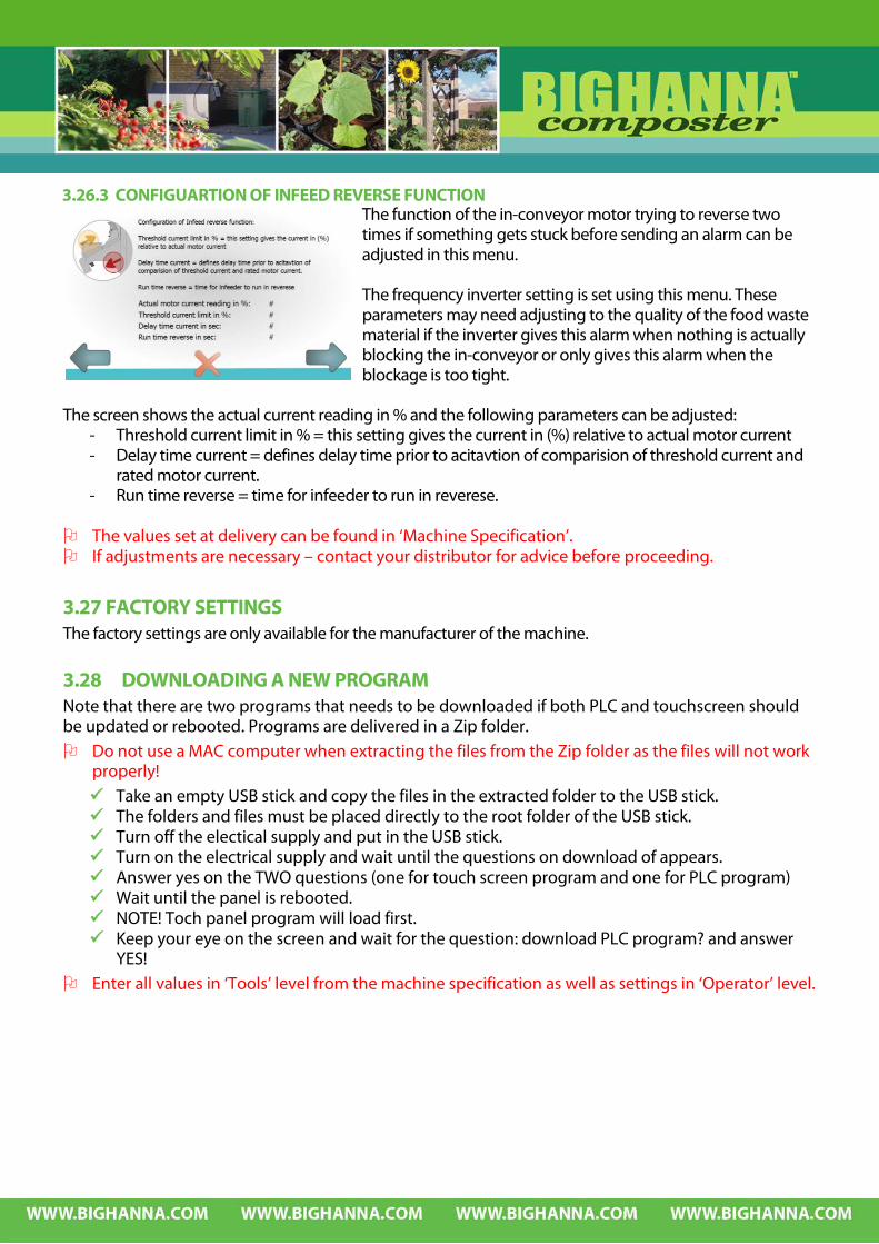
3.26.3 CONFIGUARTION OF INFEED REVERSE FUNCTION The function of the in-conveyor motor trying to reverse two times if something gets stuck before sending an alarm can be adjusted in this menu. The frequency inverter setting is set using this menu. These parameters may need adjusting to the quality of the food waste material if the inverter gives this alarm when nothing is actually blocking the in-conveyor or only gives this alarm when the blockage is too tight.
The screen shows the actual current reading in % and the following parameters can be adjusted:
- Threshold current limit in % = this setting gives the current in (%) relative to actual motor current - Delay time current = defines delay time prior to acitavtion of comparision of threshold current and
rated motor current. - Run time reverse = time for infeeder to run in reverese.
The values set at delivery can be found in ‘Machine Specification’. If adjustments are necessary – contact your distributor for advice before proceeding.
3.27 FACTORY SETTINGS The factory settings are only available for the manufacturer of the machine.
3.28 DOWNLOADING A NEW PROGRAM Note that there are two programs that needs to be downloaded if both PLC and touchscreen should be updated or rebooted. Programs are delivered in a Zip folder. Do not use a MAC computer when extracting the files from the Zip folder as the files will not work
properly! Take an empty USB stick and copy the files in the extracted folder to the USB stick. The folders and files must be placed directly to the root folder of the USB stick. Turn off the electical supply and put in the USB stick. Turn on the electrical supply and wait until the questions on download of appears. Answer yes on the TWO questions (one for touch screen program and one for PLC program) Wait until the panel is rebooted. NOTE! Toch panel program will load first. Keep your eye on the screen and wait for the question: download PLC program? and answer
YES! Enter all values in ‘Tools’ level from the machine specification as well as settings in ‘Operator’ level.

4 BIOLOGICAL PROCESS More detailed information on the definition of food waste see 1.6.4 Function, range of application
and limitations of use. The information about obtaining temperatures and the biological process in this manual
constitutes no guarantee to do so by the manufacturer. The quality of the produced compost, temperatures, moisture content etc is depending solely on
the raw material (food waste and absorbent material) and on how the machine is operated. The manufacturer or distributor can therefore never guarantee the performance of any machine.
To compost food waste we use nature’s own process in a perfect balance. Microorganisms decompose the waste material. A biological combustion is taking place inside the Composter. The biological process requires:
Oxygen + Carbon and Nitrogen (C:N) + Heat + Moisture → in balance.
4.1 OXYGEN - AERATION OF THE MATERIAL Oxygen + Carbon and Nitrogen (C:N) + Heat + Moisture → in balance. If the decomposing process lacks oxygen there will be a fermentation process. When the cylinder rotates, all material inside the cylinder is provided with oxygen. For further aeration of the material, the Composter has a fan installed that works continuously at low speed and produces a proper air flow. The biological process is highly dependent on the air supply in the cylinder. As shown in the picture on the next page we use the biological heat from the cylinder to pre-heat the air in between cylinder and hood. Both cylinder and hood are insulated. Note! Without the fan functioning properly and ventilation path being kept clean, the biological
process will not work! Clean ventilation filter regularly! The regulation of the fan is only for the speed of the fan during the waiting time. When the cylinder rotates the fan is always working at full speed. The fan is the “lungs” of the Big Hanna – if the biological process does not get the right amount of oxygen the result will be a bad smell so it is important to regularly check the airflow and to understand how the airflow works.
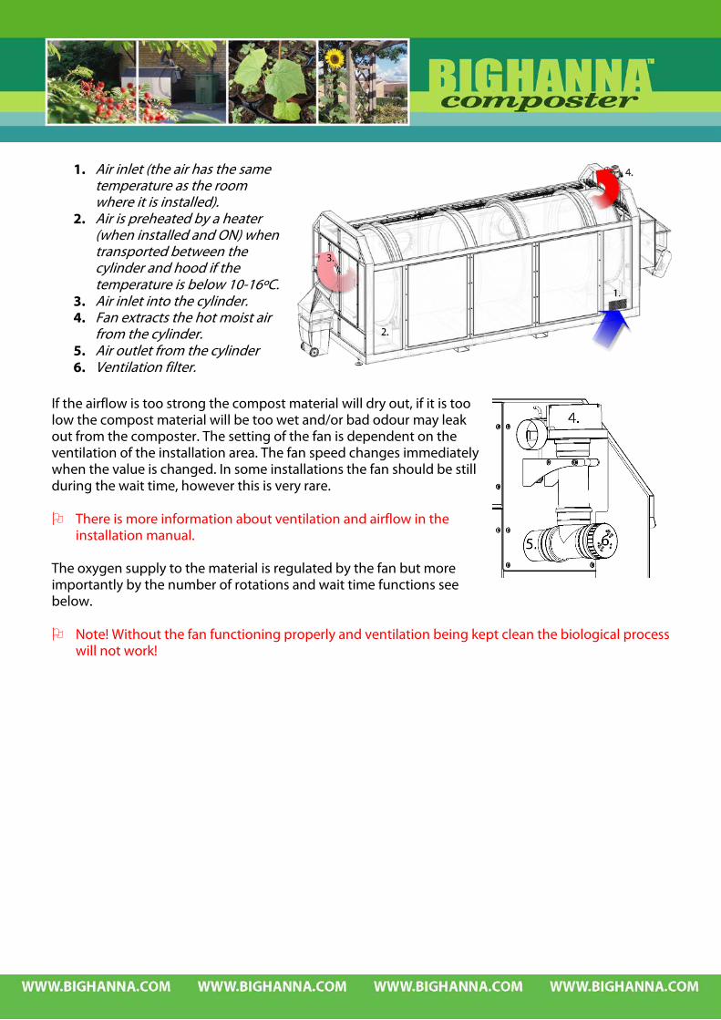
1. Air inlet (the air has the same
temperature as the room where it is installed).
2. Air is preheated by a heater (when installed and ON) when transported between the cylinder and hood if the temperature is below 10-16ºC.
3. Air inlet into the cylinder. 4. Fan extracts the hot moist air
from the cylinder. 5. Air outlet from the cylinder 6. Ventilation filter.
If the airflow is too strong the compost material will dry out, if it is too low the compost material will be too wet and/or bad odour may leak out from the composter. The setting of the fan is dependent on the ventilation of the installation area. The fan speed changes immediately when the value is changed. In some installations the fan should be still during the wait time, however this is very rare. There is more information about ventilation and airflow in the
installation manual. The oxygen supply to the material is regulated by the fan but more importantly by the number of rotations and wait time functions see below. Note! Without the fan functioning properly and ventilation being kept clean the biological process
will not work!

4.2 CARBON AND NITROGEN – THE FOOD WASTE Oxygen + Carbon and Nitrogen (C:N) + Heat + Moisture → in balance. Both carbon and nitrogen are necessary for the micro-organisms. The carbon/nitrogen content in the waste material should be 25-30/1. In waste material from households (in Sweden) there is normally 15/1 carbon/nitrogen and therefore the material requires an addition of sawdust or pelletised sawdust in order to add carbon. These absorbing materials also make the waste material inside the cylinder less compact. We recommend pelletised sawdust. The compost is a living organism and should be ”fed” with care. The best result is obtained if there is a good mixture of food waste material, which is put into the machine. If 10% or more of the total amount of waste material is fish and meat it is necessary to add more sawdust / pelletised sawdust in order to restore the carbon/nitrogen balance in the Composter. However this tends to lead to dehydration of the material inside the machine. It is quite difficult to obtain a biological process if the waste material contains more than 10% of meat/fish. The biological process could function but large amounts of protein will result in a bad odour. Waste material that contains food waste with large amounts of vinegar essence will kill the micro-organisms. Therefore this kind of material should be mixed with other waste material in order to reduce concentration of vinegar. If there is too much carbon content, the biological process will slow down. Too little carbon will
make it difficult to bind the nitrogen and this will evaporate as ammonium and cause a problem with foul smell.
The easiest way to achieve a good biological process is to put a mixture of food waste into the composter.

4.2.1 WHAT TO PUT INTO THE COMPOSTER More detailed information on the definition of food waste see 1.6.4 Function, range of application
and limitations of use.
RAW AND COOKED LEFTOVERS FROM MEAT, FISH, FRUITS
VEGETABLES, COFFEE GRINDINGS INCL USED FILTERS, EGGS, EGGSHELLS, AND BREAD
DAIRY PRODUCTS, RICE, POTATOES AND ROOT VEGETABLES S HOUSEPLANTS AND GARDEN WASTE (CUT INTO SMALL
PIECES).
CUT THE WASTE MATERIAL It is important that all waste material that is put into the composter is cut in small pieces (2-3 cm) giving the micro-organisms a larger surface on the waste material to work on. By cutting the material the quality of the outgoing compost material will be improved. Citrus fruits have to be cut before being put into the composter because these fruits are treated with biocides on the peel and which stop the micro-organisms to getting the decomposing process started. If the citrus fruits are put in without being cut they will eventually come out whole and will have to be cleared from the other composted material. CUT CITRUS FRUITS CUT POTATOES AND CUT PLANTS AND
ROOT VEGETABLES GARDEN REFUSE

4.2.2 WHAT NOT TO PUT INTO THE COMPOSTER: More detailed information on the definition of food waste see 1.6.4 Function, range of application
and limitations of use. The composter ”produces” compost material that is good for use as fertilizer in gardens etc. In order to produce a fertilizer the waste material must not contain anything that might damage the biological process or the cylinder. Material that under no circumstances should be put into the composter is:
Crepe paper Steel wool Leather Cigarette Treated wood Soft plastic Diapers
String Cat sand Ashes Rubber Bags from Branches Textiles vacuum- cleaner
MATERIAL FOR RECYCLING OR TREATMENT
Glass Cardboard Metal Aluminium Pet and glass Take to recy- Take to recy- Take to recy- Take back to bottles ling yard ling yard ling yard the store Take back to the store
Newspapers Packages in Batteries Medicines Chemicals Take to recy- Take to recy- Take to recy- Take back to Take to the ling yard ling yard ling yard the pharmacy environmental station
I CAN NOT COMPOST PLASTIC BAGS!!!
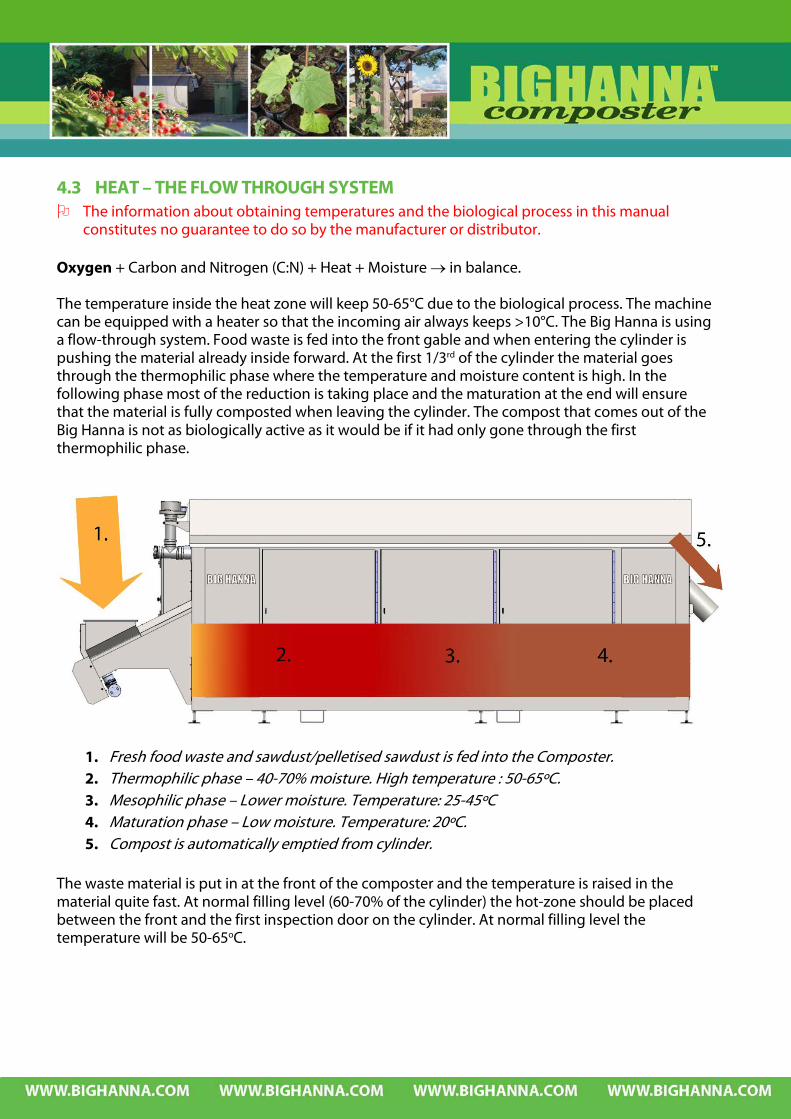
4.3 HEAT – THE FLOW THROUGH SYSTEM The information about obtaining temperatures and the biological process in this manual
constitutes no guarantee to do so by the manufacturer or distributor. Oxygen + Carbon and Nitrogen (C:N) + Heat + Moisture → in balance. The temperature inside the heat zone will keep 50-65°C due to the biological process. The machine can be equipped with a heater so that the incoming air always keeps >10°C. The Big Hanna is using a flow-through system. Food waste is fed into the front gable and when entering the cylinder is pushing the material already inside forward. At the first 1/3rd of the cylinder the material goes through the thermophilic phase where the temperature and moisture content is high. In the following phase most of the reduction is taking place and the maturation at the end will ensure that the material is fully composted when leaving the cylinder. The compost that comes out of the Big Hanna is not as biologically active as it would be if it had only gone through the first thermophilic phase.
1. Fresh food waste and sawdust/pelletised sawdust is fed into the Composter. 2. Thermophilic phase – 40-70% moisture. High temperature : 50-65ºC. 3. Mesophilic phase – Lower moisture. Temperature: 25-45ºC 4. Maturation phase – Low moisture. Temperature: 20ºC. 5. Compost is automatically emptied from cylinder.
The waste material is put in at the front of the composter and the temperature is raised in the material quite fast. At normal filling level (60-70% of the cylinder) the hot-zone should be placed between the front and the first inspection door on the cylinder. At normal filling level the temperature will be 50-65oC.

Towards the end of the cylinder the temperature drops and the maturation phase of the decomposing process takes place. When the material reaches the outlet pipe the material will be well decomposed. If the hot-zone is placed at the end of the cylinder the biological process has started too late. The material that comes out from the composter is hot and not fully decomposed. In order to make the composter to work properly the hot-zone should be moved towards the front of the composter. The most common reason for the hot-zone to be in the back of the cylinder is that there is too much waste material being fed into the composter or that the material is too wet. It is then recommended to stop feeding waste material into the composter and instead recycling the unfinished compost material that is coming out of the composter. This unfinished compost material contains micro-organisms that are placed in the front of the cylinder hence supporting the biological process inside the cylinder. We recommend recirculating the material to get the hot-zone moving towards the front of the
composter. If the material inside the composter does not reach the filling level of 60-70% the temperature will rarely be more than 50oC. The filling level should be about 60-70% to achieve the right temperature. The ideal is to have about 60oC in the hot-zone placed between the front end and the first inspection door and approximately 20-30oC in the outgoing compost material.
Front end to the left. The above is the “temperature curve” inside the composter when the biological process is functioning properly.
If the hot-zone is placed at the end of the cylinder the biological process has started too late.
Temperatures above 65oC are not desirable since the emissions of nitrogen will increase rapidly when temperature is above 65oC. The hot-zone should be about 50-65oC to efficiently kill the pathogen bacteria. However depending on the mixture of food waste that is fed into the machine temperatures are sometimes less than 50-65°C. This is the case especially when only vegetables and fruit is composted i.e. no meat or fish. These temperatures are normal and the efficiency of the biological process must be judged by the quality of the compost. Pathogen bacteria will not survive an otherwise functioning biological process at lower temperatures.
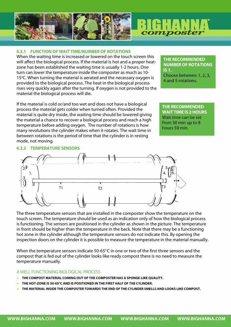
4.3.1 FUNCTION OF WAIT TIME/NUMBER OF ROTATIONS When the waiting time is increased or lowered on the touch screen this will affect the biological process. If the material is hot and a proper heat-zone has been established the waiting time is usually 1-2 hours. One turn can lower the temperature inside the composter as much as 10-15oC. When turning the material is aerated and the necessary oxygen is provided to the biological process. The heat in the biological process rises very quickly again after the turning. If oxygen is not provided to the material the biological process will die. If the material is cold or/and too wet and does not have a biological process the material gets colder when turned often. Provided the material is quite dry inside, the waiting time should be lowered giving the material a chance to recover a biological process and reach a high temperature before adding oxygen. The number of rotations is how many revolutions the cylinder makes when it rotates. The wait time in between rotations is the period of time that the cylinder is in resting mode, not moving.
4.3.2 TEMPERATURE SENSORS
The three temperature sensors that are installed in the composter show the temperature on the touch screen. The temperature should be used as an indication only of how the biological process is functioning. The sensors are positioned in the cylinder as shown in the picture. The temperature in front should be higher than the temperature in the back. Note that there may be a functioning hot zone in the cylinder although the temperature sensors do not indicate this. By opening the inspection doors on the cylinder it is possible to measure the temperature in the material manually. When the temperature sensors indicate 50-65°C in one or two of the first three sensors and the compost that is fed out of the cylinder looks like ready compost there is no need to measure the temperature manually. A WELL FUNCTIONING BIOLOGICAL PROCESS THE COMPOST MATERIAL COMING OUT OF THE COMPOSTER HAS A SPONGE-LIKE QUALITY.
THE HOT-ZONE IS 50-65°C AND IS POSITIONED IN THE FIRST HALF OF THE CYLINDER.
THE MATERIAL INSIDE THE COMPOSTER TOWARDS THE END OF THE CYLINDER SMELLS AND LOOKS LIKE COMPOST.
THE RECOMMENDED NUMBER OF ROTATIONS IS 1. Choose between: 1, 2, 3, 4 and 5 rotations.
THE RECOMMENDED WAIT TIME IS 2 HOURS Wait time can be set from 30 min up to 8 hours 59 min.

4.4 MOISTURE CONTROL Oxygen + Carbon and Nitrogen (C:N) + Heat + Moisture → in balance.
4.4.1 MOISTURE - THE THEORETICAL BACKGROUND Water is necessary for all living organisms. The cells contain more than 90% of water and all nutrients that they absorb are also dissolved in water. The water also has to be in contact with the solid material it will decompose, with the air that supplies the oxygen and with the micro-organisms. The supply of water and air is therefore dependent on each other. When water fills the pores in the material there is no access for oxygen. There has to be a balance between water content, air and the surface of the solid material. The accessibility of water is not only controlled by how much water there is it also depends on how hard the water is bound to the particles and salt in soluble liquid. This means that the moisture content is a variable which should be used with caution, for example two samples, one of mud and one of sand, can have the same moisture content but the water in mud is inaccessible and the water in sand is accessible. The guidelines for moisture content which is stated in this manual are indications only and applies to typical mixed food waste which is mixed with the appropriate amount of sawdust / pelletised sawdust.
4.4.2 MOISTURE – THE PRACTICAL TEST This practical test below gives a good indication on if typical mixed food waste which is mixed in the cylinder with sawdust or pelletised sawdust has the correct moisture level or is too wet. Open the inspection hatches by releasing the holder and unscrewing the knob from its
bottom position. Turn the inspection hatch sideways to open it. Pick some material up and squeeze it in your hand – if you easily can squeeze water from
the material – it is far too wet! If no (or very little) water is visible open your palm and carefully shake the material, it should
fall into smaller pieces. If it remains in one piece then the material is too wet. If no (or very little) water is visible when the material is squeezed and it falls into smaller
pieces when you shake your hand this is the correct moisture level that the material in the first half of the cylinder should have.
Make sure the inspection door on the hood is properly closed. The touch screen will show an alarm symbol on the inspection doors and a warning text if they are not properly closed. Once the doors are closed, the alarm symbol disappears. The machine needs to be started up again after the inspection doors have been opened by resetting the blue reset button below the touch screen.
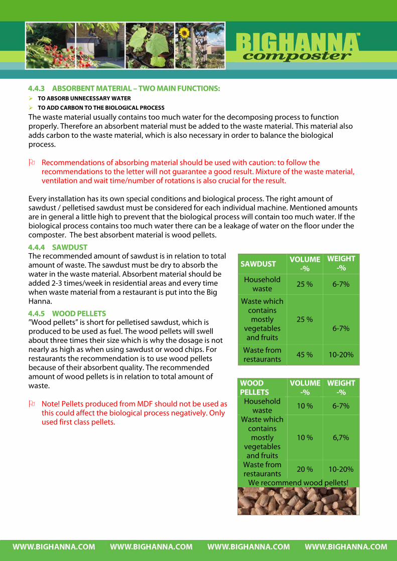
4.4.3 ABSORBENT MATERIAL – TWO MAIN FUNCTIONS: TO ABSORB UNNECESSARY WATER
TO ADD CARBON TO THE BIOLOGICAL PROCESS
The waste material usually contains too much water for the decomposing process to function properly. Therefore an absorbent material must be added to the waste material. This material also adds carbon to the waste material, which is also necessary in order to balance the biological process. Recommendations of absorbing material should be used with caution: to follow the
recommendations to the letter will not guarantee a good result. Mixture of the waste material, ventilation and wait time/number of rotations is also crucial for the result.
Every installation has its own special conditions and biological process. The right amount of sawdust / pelletised sawdust must be considered for each individual machine. Mentioned amounts are in general a little high to prevent that the biological process will contain too much water. If the biological process contains too much water there can be a leakage of water on the floor under the composter. The best absorbent material is wood pellets.
4.4.4 SAWDUST The recommended amount of sawdust is in relation to total amount of waste. The sawdust must be dry to absorb the water in the waste material. Absorbent material should be added 2-3 times/week in residential areas and every time when waste material from a restaurant is put into the Big Hanna.
4.4.5 WOOD PELLETS ”Wood pellets” is short for pelletised sawdust, which is produced to be used as fuel. The wood pellets will swell about three times their size which is why the dosage is not nearly as high as when using sawdust or wood chips. For restaurants the recommendation is to use wood pellets because of their absorbent quality. The recommended amount of wood pellets is in relation to total amount of waste. Note! Pellets produced from MDF should not be used as
this could affect the biological process negatively. Only used first class pellets.
SAWDUST VOLUME-%
WEIGHT -%
Household waste 25 % 6-7%
Waste which contains mostly
vegetables and fruits
25 %
6-7%
Waste from restaurants
45 % 10-20%
WOOD PELLETS
VOLUME -%
WEIGHT -%
Household waste 10 % 6-7%
Waste which contains mostly
vegetables and fruits
10 % 6,7%
Waste from restaurants 20 % 10-20%
We recommend wood pellets!
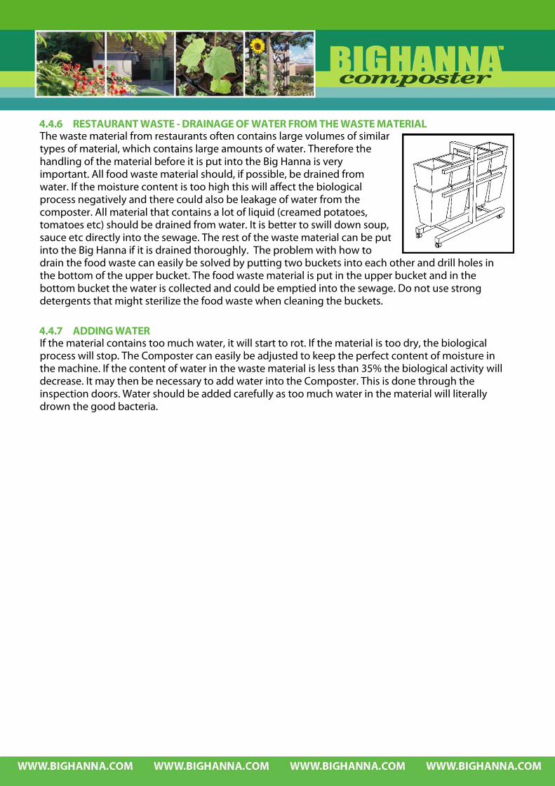
4.4.6 RESTAURANT WASTE - DRAINAGE OF WATER FROM THE WASTE MATERIAL The waste material from restaurants often contains large volumes of similar types of material, which contains large amounts of water. Therefore the handling of the material before it is put into the Big Hanna is very important. All food waste material should, if possible, be drained from water. If the moisture content is too high this will affect the biological process negatively and there could also be leakage of water from the composter. All material that contains a lot of liquid (creamed potatoes, tomatoes etc) should be drained from water. It is better to swill down soup, sauce etc directly into the sewage. The rest of the waste material can be put into the Big Hanna if it is drained thoroughly. The problem with how to drain the food waste can easily be solved by putting two buckets into each other and drill holes in the bottom of the upper bucket. The food waste material is put in the upper bucket and in the bottom bucket the water is collected and could be emptied into the sewage. Do not use strong detergents that might sterilize the food waste when cleaning the buckets.
4.4.7 ADDING WATER If the material contains too much water, it will start to rot. If the material is too dry, the biological process will stop. The Composter can easily be adjusted to keep the perfect content of moisture in the machine. If the content of water in the waste material is less than 35% the biological activity will decrease. It may then be necessary to add water into the Composter. This is done through the inspection doors. Water should be added carefully as too much water in the material will literally drown the good bacteria.


5 START-UP ROUTINES AND FOLLOW-UP 5.1 ROUTINES FOR START-UP – HOUSEHOLD WASTE The key-point in a start-up phase is to facilitate in every way a rich bacterial activity. Normally food from households has, in practice, already started the decomposing process when loaded into the composter. In general therefore this situation is not a problem - within a few days the temperature is rising and the biological process has commenced. THE FIRST TWO BAGS OF COMPOST MATERIAL THAT THE COMPOSTER PRODUCES SHOULD
BE PUT INTO THE COMPOSTER AGAIN. DURING THE START-UP PERIOD THE BIOLOGICAL PROCESS REQUIRES MORE ABSORBENT
MATERIAL. DURING THE REMAINING START-UP PERIOD THE FINISHED COMPOST MATERIAL IS PREFERABLY RECYCLED ONCE IN A WHILE.
5.1.1 INITIAL STARTING BATCH When installation is made an initial starting batch of absorbent material is put into the composter plus if available one batch of horse manure and/or a batch of composted material to get a really quick start-up.
Model T480 Pellets 100 kg Manure 600 litre Compost 600 litre
5.1.2 ABSORBENT MATERIAL DURING START-UP The required amount of absorbent material during start-up will vary until the biological process has started. Within the community where the composter is installed new routines in the handling of the household waste must be carried out. In housing areas the recommendation is to appoint one person to be in charge of both the composter and adding sawdust or pellets. Every composter has its own unique biological process and therefore it is difficult to recommend how much sawdust that should be put into the composter.
5.1.3 START UP – HOUSEHOLD WASTE If the residents put their food waste into the machine themselves they may also add a proportion of sawdust / pelletised sawdust with their food waste. In some circumstances a caretaker is instructed to add sawdust / pelletised sawdust 3 times a week. If this is the case – during start-up, this schedule should be followed.
Sawdust Pellets
Model Total kgs / week Kgs to feed
3 times/week Total kgs/ week kgs to feed
3 times/week T480 240 80 240 80
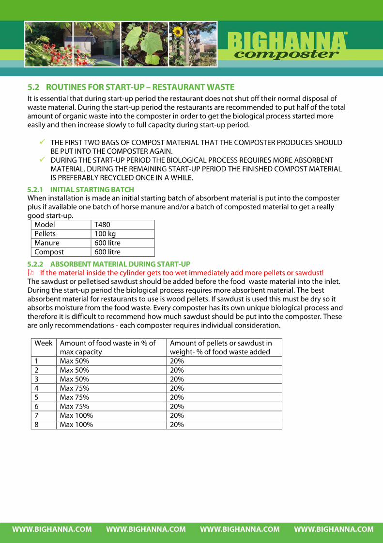
5.2 ROUTINES FOR START-UP – RESTAURANT WASTE It is essential that during start-up period the restaurant does not shut off their normal disposal of waste material. During the start-up period the restaurants are recommended to put half of the total amount of organic waste into the composter in order to get the biological process started more easily and then increase slowly to full capacity during start-up period. THE FIRST TWO BAGS OF COMPOST MATERIAL THAT THE COMPOSTER PRODUCES SHOULD
BE PUT INTO THE COMPOSTER AGAIN. DURING THE START-UP PERIOD THE BIOLOGICAL PROCESS REQUIRES MORE ABSORBENT
MATERIAL. DURING THE REMAINING START-UP PERIOD THE FINISHED COMPOST MATERIAL IS PREFERABLY RECYCLED ONCE IN A WHILE.
5.2.1 INITIAL STARTING BATCH When installation is made an initial starting batch of absorbent material is put into the composter plus if available one batch of horse manure and/or a batch of composted material to get a really good start-up.
Model T480 Pellets 100 kg Manure 600 litre Compost 600 litre
5.2.2 ABSORBENT MATERIAL DURING START-UP If the material inside the cylinder gets too wet immediately add more pellets or sawdust! The sawdust or pelletised sawdust should be added before the food waste material into the inlet. During the start-up period the biological process requires more absorbent material. The best absorbent material for restaurants to use is wood pellets. If sawdust is used this must be dry so it absorbs moisture from the food waste. Every composter has its own unique biological process and therefore it is difficult to recommend how much sawdust should be put into the composter. These are only recommendations - each composter requires individual consideration.
Week Amount of food waste in % of max capacity
Amount of pellets or sawdust in weight- % of food waste added
1 Max 50% 20% 2 Max 50% 20% 3 Max 50% 20% 4 Max 75% 20% 5 Max 75% 20% 6 Max 75% 20% 7 Max 100% 20% 8 Max 100% 20%
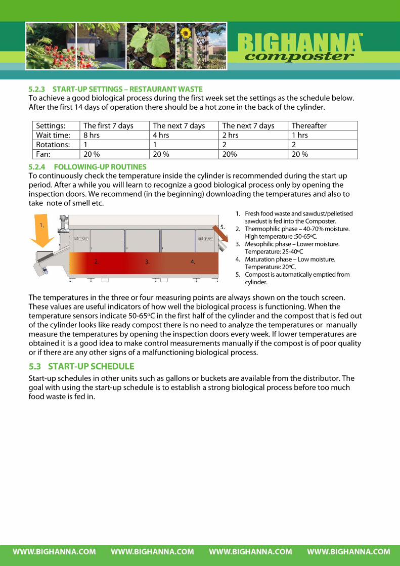
5.2.3 START-UP SETTINGS – RESTAURANT WASTE To achieve a good biological process during the first week set the settings as the schedule below. After the first 14 days of operation there should be a hot zone in the back of the cylinder.
Settings: The first 7 days The next 7 days The next 7 days Thereafter Wait time: 8 hrs 4 hrs 2 hrs 1 hrs Rotations: 1 1 2 2 Fan: 20 % 20 % 20% 20 %
5.2.4 FOLLOWING-UP ROUTINES To continuously check the temperature inside the cylinder is recommended during the start up period. After a while you will learn to recognize a good biological process only by opening the inspection doors. We recommend (in the beginning) downloading the temperatures and also to take note of smell etc.
The temperatures in the three or four measuring points are always shown on the touch screen. These values are useful indicators of how well the biological process is functioning. When the temperature sensors indicate 50-65ºC in the first half of the cylinder and the compost that is fed out of the cylinder looks like ready compost there is no need to analyze the temperatures or manually measure the temperatures by opening the inspection doors every week. If lower temperatures are obtained it is a good idea to make control measurements manually if the compost is of poor quality or if there are any other signs of a malfunctioning biological process.
5.3 START-UP SCHEDULE Start-up schedules in other units such as gallons or buckets are available from the distributor. The goal with using the start-up schedule is to establish a strong biological process before too much food waste is fed in.
1. Fresh food waste and sawdust/pelletised sawdust is fed into the Composter.
2. Thermophilic phase – 40-70% moisture. High temperature :50-65ºC.
3. Mesophilic phase – Lower moisture. Temperature: 25-40ºC
4. Maturation phase – Low moisture. Temperature: 20ºC.
5. Compost is automatically emptied from cylinder.
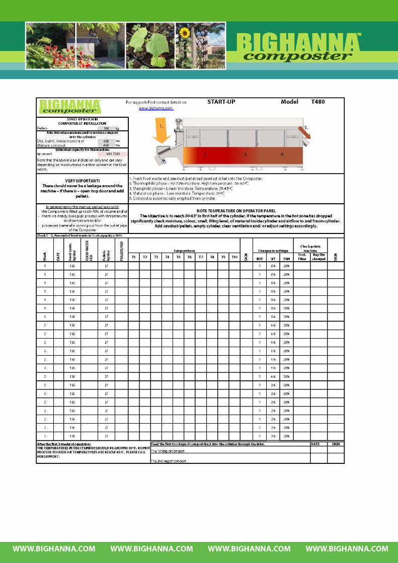


6 TROUBLESHOOTING THE BIOLOGICAL PROCESS 6.1 SCHEDULE - BIOLOGICAL PROCESS NOTE – THIS IS ONLY ABOUT THE HOT ZONE!!! See below for more details about each problem. To understand low / medium / high moisture – read 4.4 Moisture control.
LOW
MO
ISTU
RE
(LES
S TH
AN
35%
- PR
OCE
SS IS
STO
PPED
)
LOW TEMPERATURE LESS THAN 50O C
NORMAL TEMPERATURE 50-65 O C
HIGH TEMPERATURE MORE THAN 65 O C
Either caused by too much sawdust and no biological process. Compost material is not decomposed. CAREFULLY ADD WATER INCREASE WAIT TIME LOWER NUMBER OF
ROTATIONS
If temperatures have increased looking back one week: ADD MORE WATERY WASTE ADD LUKE WARM WATER LOWER FAN-SPEED
LOWER SAWDUST AMOUNT INCREASE FAN SPEED INCREASE NUMBER OF
ROTATIONS LOWER WAIT TIME
Or caused by fully decomposed burnt out material – no energy. ADD NEW MATERIAL LOWER FAN-SPEED
If the temperatures have dropped looking back one week: ADD LUKE WARM WATER INCREASE WAITING TIME LOWER NUMBER OF
ROTATIONS
MED
IUM
MO
ISTU
RE
(40-
70%
)
Could be caused by too much material. LOWER INPUT OF FOOD
WASTE TEMPORARILY.
MEDIUM MOISTURE (40-70%) AND NORMAL TEMPERATURE 50-65OC = GOOD BIOLOGICAL PROCESS IN THE HOT ZONE POSITIONED IN THE FIRST HALF OF THE CYLINDER
CHECK AIRFLOW AND IF
THIS IS O.K. LOWER WAITING TIME INCREASE NUMBER OF
ROTATIONS
Caused by incorrect C/N quota. ADD MORE SAWDUST WITH
FOOD WASTE
HIG
H M
OIS
TURE
(M
ORE
TH
AN
70%
)
Water is stopping the biological process. STOP FEEDING FOOD
WASTE ADD SAWDUST IN THE INSP.
DOORS LOWER WAIT TIME INCREASE NUMBER OF
ROTATIONS
Risk for leakage from the machine. ADD MORE SAWDUST LOWER WAITING TIME INCREASE NUMBER OF
ROTATIONS INCREASE FAN-SPEED
LOWER WAITING TIME INCREASE NUMBER OF
ROTATIONS CAREFULLY ADD MORE
SAWDUST INCREASE FAN-SPEED
Position caused by Lacto acid Bacteria, foul smell and yellowish colour. ADD SAWDUST IN
INSPECTION DOORS WAITING TIME 8 HR
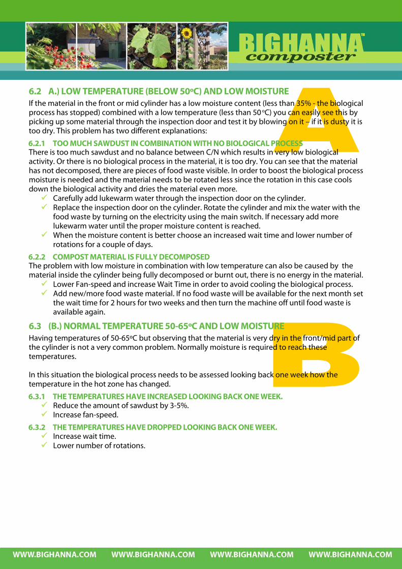
6.2 A.) LOW TEMPERATURE (BELOW 50ºC) AND LOW MOISTURE If the material in the front or mid cylinder has a low moisture content (less than 35% - the biological process has stopped) combined with a low temperature (less than 50 oC) you can easily see this by picking up some material through the inspection door and test it by blowing on it – if it is dusty it is too dry. This problem has two different explanations:
6.2.1 TOO MUCH SAWDUST IN COMBINATION WITH NO BIOLOGICAL PROCESS There is too much sawdust and no balance between C/N which results in very low biological activity. Or there is no biological process in the material, it is too dry. You can see that the material has not decomposed, there are pieces of food waste visible. In order to boost the biological process moisture is needed and the material needs to be rotated less since the rotation in this case cools down the biological activity and dries the material even more. Carefully add lukewarm water through the inspection door on the cylinder. Replace the inspection door on the cylinder. Rotate the cylinder and mix the water with the
food waste by turning on the electricity using the main switch. If necessary add more lukewarm water until the proper moisture content is reached.
When the moisture content is better choose an increased wait time and lower number of rotations for a couple of days.
6.2.2 COMPOST MATERIAL IS FULLY DECOMPOSED The problem with low moisture in combination with low temperature can also be caused by the material inside the cylinder being fully decomposed or burnt out, there is no energy in the material. Lower Fan-speed and increase Wait Time in order to avoid cooling the biological process. Add new/more food waste material. If no food waste will be available for the next month set
the wait time for 2 hours for two weeks and then turn the machine off until food waste is available again.
6.3 (B.) NORMAL TEMPERATURE 50-65ºC AND LOW MOISTURE Having temperatures of 50-65ºC but observing that the material is very dry in the front/mid part of the cylinder is not a very common problem. Normally moisture is required to reach these temperatures. In this situation the biological process needs to be assessed looking back one week how the temperature in the hot zone has changed.
6.3.1 THE TEMPERATURES HAVE INCREASED LOOKING BACK ONE WEEK. Reduce the amount of sawdust by 3-5%. Increase fan-speed.
6.3.2 THE TEMPERATURES HAVE DROPPED LOOKING BACK ONE WEEK. Increase wait time. Lower number of rotations.

6.4 (C.) HIGH TEMPERATURE, MORE THAN 65ºC AND LOW MOISTURE The combination of high temperature and low moisture content is not common. In order to cool the biological process increase fan speed and number of rotations at the same time as the wait time is lowered so that the compost material is aerated more. Also lower the amount of sawdust by 3-10% in relation to food waste. Lower sawdust amount by 3-10%. Increase fan speed. Increase number of rotations. Lower wait time.
6.5 (D.) LOW TEMPERATURE AND MEDIUM MOISTURE Having low temperatures in combination with a good medium moisture content could be caused by either too much food waste being fed in or that the composter has been fed with too much material containing nitrogen which leads to incorrect C/N balance.
6.5.1 TOO MUCH FOOD WASTE IS ADDED If too much food waste is put into the cylinder this will result in low temperatures. In this case the input of food waste should be lowered temporarily so that the biological process has time to recover. If possible feed small amounts of food waste many times per day. Lower input of food waste.
6.5.2 INCORRECT C/N BALANCE If there is no balance between carbon and nitrogen this can result in low temperatures even if the material has a good medium moisture content. The material containing nitrogen from household waste is mainly meat and fish. If there is small lumps (1-3 cm) in the compost material the C/N quota is usually the problem. Add extra sawdust / pelletized sawdust into the material through the inspection doors. Replace the inspection door on the cylinder. Rotate the cylinder and mix the sawdust /
pelletized sawdust with the food waste by turning on the electricity using the main switch. If necessary add more sawdust / pelletized sawdust until the proper moisture content is reached.
Increase the amount of sawdust / pelletized sawdust which is added to the food waste by 5-50% from what was used previously.
6.6 (E.) MEDIUM MOISTURE AND NORMAL TEMPERATURE – GOOD HOT ZONE Medium moisture and a normal temperature in the hot zone inside the cylinder is illustrated in the first 1/3 red block (1). The position does not have to be the first
1/3 but should ideally at least be in the first half of the cylinder.

6.7 (F.) MEDIUM MOISTURE - HIGH TEMPERATURE (MORE THAN 65ºC) If the temperature is higher than 65ºC there is usually a problem with air supply to the compost material. If the temperatures are higher than 65ºC there can be a smell of ammonia.
6.7.1 BLOCKAGE IN VENTILATION SYSTEM – SMELL OF AMMONIA The first symptom of a blockage in the ventilation system is very high temperatures. Check that the airflow is functioning properly, outlet cover/bag is in position and that the
fan is working. Make sure fan is functioning properly. Remove and clean the ventilation filter and check the
airflow. Make sure that the outlet cover / bag is tight on the outlet.
Check that the airflow is functioning well through the biofilter (if installed).
Note! Without the fan functioning properly and ventilation being kept clean the biological process will not work! Clean ventilation regularly!
6.7.2 MATERIAL IS NOT AERATED ENOUGH – SMELL OF AMMONIA If there is no blockage in the ventilation system change the parameters so that the compost material is aerated more. Lower wait time. Increase number of rotations. Increase fan speed.
Emtpy the biofilter using the ball valve when necessary!

6.8 (G.) HIGH MOISTURE – LOW TEMPERATURE (LESS THAN 50ºC) If the temperature is low and the moisture content is high in the first half of the cylinder this could be caused by water content being too high or lacto bacteria. In this situation there can be leakage from the machine and this must be cleaned up immediately and the biological process must be adjusted.
6.8.1 TOO MUCH WATER IN THE MATERIAL There can be too much water in the material if the ventilation system is not functioning properly, no water is vented off. The problem can also be caused by filling level being too high, that not enough sawdust / pelletized sawdust has been added or that the food waste fed in is simply too wet and must be more carefully drained. Check that the airflow is functioning properly, outlet
cover/bag is in position and that the fan is working. Make sure fan is functioning properly. Remove and clean the ventilation filter and check the
airflow. Make sure that the outlet cover / bag is tight on the
outlet. Check that the airflow is functioning well through the
biofilter (if installed). Note! Without the fan functioning properly and ventilation
being kept clean the biological process will not work! Clean ventilation regularly! If the temperature is very low and moisture content very high it may be
necessary to stop feeding material for 2-3 days. Alternatively put some extra sawdust or pelletised sawdust on the food waste material when feeding the machine. For a limited period of time add 50 % sawdust to volume of waste.
Open the inspection door and put in sawdust/pelletized sawdust in order to dry the material inside. If the material inside the cylinder is very wet – add a bag of sawdust or a bag of pelletized sawdust.
Replace the inspection door on the cylinder. Rotate the cylinder and mix the sawdust / pelletized sawdust with the food waste by turning on the electricity using the main switch.
Turn off the electricity using the main switch and open the inspection door again to inspect the compost material. If necessary repeat the above steps adding more sawdust / pelletized sawdust until the proper moisture content is reached.
Increase number of rotations. Lower wait time. Increase the speed for the fan for a period of time (a couple of days). Check the filling level inside the machine. If necessary empty out material.
Emtpy the biofilter using the ball valve when necessary!

6.8.2 LACTO BACTERIA If the material is bright yellow and has a sour, foul distinctive smell the problem is lacto bacteria. Contact the distributor for advice. The problem with lacto bacteria is not very common but can be hard to overcome. One
solution is to empty the cylinder and perform a new start-up procedure. (The cylinder can be emptied by a vacuum truck, through the inspection door.)
The other solution is to stop the feeding of food waste add a massive amount of sawdust (see below) and if possible burnt horse manure and / or finished compost material.
Open the inspection doors and put in a lot of sawdust/pelletised sawdust / burnt horse manure / burnt compost in order to dry the material inside and introduce good bacteria which will replace the lacto bacteria.
Replace the inspection door on the cylinder. Rotate the cylinder and mix the sawdust / pelletized sawdust with the food waste by turning on the electricity using the main switch.
Turn off the electricity using the main switch and open the inspection door again to inspect the compost material. If necessary repeat the above steps adding more sawdust / pelletised sawdust until the proper moisture content is reached.
Turn off the machine for 8-16 hours and repeat this procedure 1-3 times until the temperature has increased and the colour of the material is brown and the smell is gone.
Contact your distributor for support.
6.9 (H) NORMAL TEMPERATURE (50-65ºC) AND HIGH MOISTURE If the temperature is normal but the material is too wet this is easily adjusted with adding more sawdust / pelletized sawdust and introducing more air to the material by rotating the cylinder more often. Add more sawdust (10-50% increase) with the food waste. Lower wait time. Increase number of rotations. Increase fan-speed.

6.10 (I) HIGH TEMPERATURE (MORE THAN 65ºC) AND HIGH MOISTURE If temperatures are high and the material is wet there can be a smell of manure, rubbish or rotten food which is indicating that there is not enough oxygen in the biological process.
Make sure fan is functioning properly. Remove and clean the ventilation filter and check the airflow. Make sure that the outlet cover / bag is tight on the outlet. Check that the airflow is functioning well through the biofilter (if installed).
Note! Without the fan functioning properly and ventilation being kept clean the biological process will not work! Clean ventilation regularly!
Lower wait time. Increase number of rotations. Carefully add more sawdust 5-20%. Increase fan-speed.
6.11 RESETTING THE COMPOSTER The above measures are for stabilising the composter in case of an emergency. When the conditions return to normal the setting on the control panel also should be set to what is normal for the composter in question.
Emtpy the biofilter using the ball valve when necessary!


7 INTEGRATED DESIGN Note! Machines can be ordered according to customer’s specification and pictures and
description in this manual may not apply directly in these circumstances. Always consult ‘Machine specification’ for details on each specific machine.
Note! Susteco AB reserves the right to modify, at any time and without notice, any or all of its products’ features, designs, components and specifications.
7.1 GENERAL LAYOUT Food waste and pellets or sawdust is added through the inlet. The material is mixed inside the cylinder when it is rotating. The finished compost material is emptied automatically at the end of the cylinder into a bag. The material can be inspected through the inspection door on the cylinder.
1. Infeed hopper 2. Infeed hopper lid 3. Safety magnet contact 4. Connection point for drain from infeed
hopper 5. Ventilation filter (110091) 6. Fan (110390) 7. Electrical cabinet 8. Emergency stop button (110125) 9. Touch screen 10. First inspection door on hood 11. Second inspection door on hood 12. Third inspection door on hood 13. Feet (11) (111110) 14. Fourth inspection door on hood 15. Air inlet 16. Output pipe 17. Outlet cover (200110) 18. Bin
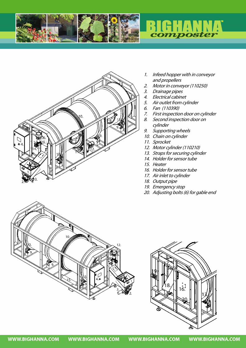
1. Infeed hopper with in conveyor and propellers
2. Motor in conveyor (110250) 3. Drainage pipes 4. Electrical cabinet 5. Air outlet from cylinder 6. Fan (110390) 7. First inspection door on cylinder 8. Second inspection door on
cylinder 9. Supporting wheels 10. Chain on cylinder 11. Sprocket 12. Motor cylinder (110210) 13. Straps for securing cylinder 14. Holder for sensor tube 15. Heater 16. Holder for sensor tube 17. Air inlet to cylinder 18. Output pipe 19. Emergency stop 20. Adjusting bolts (6) for gable end
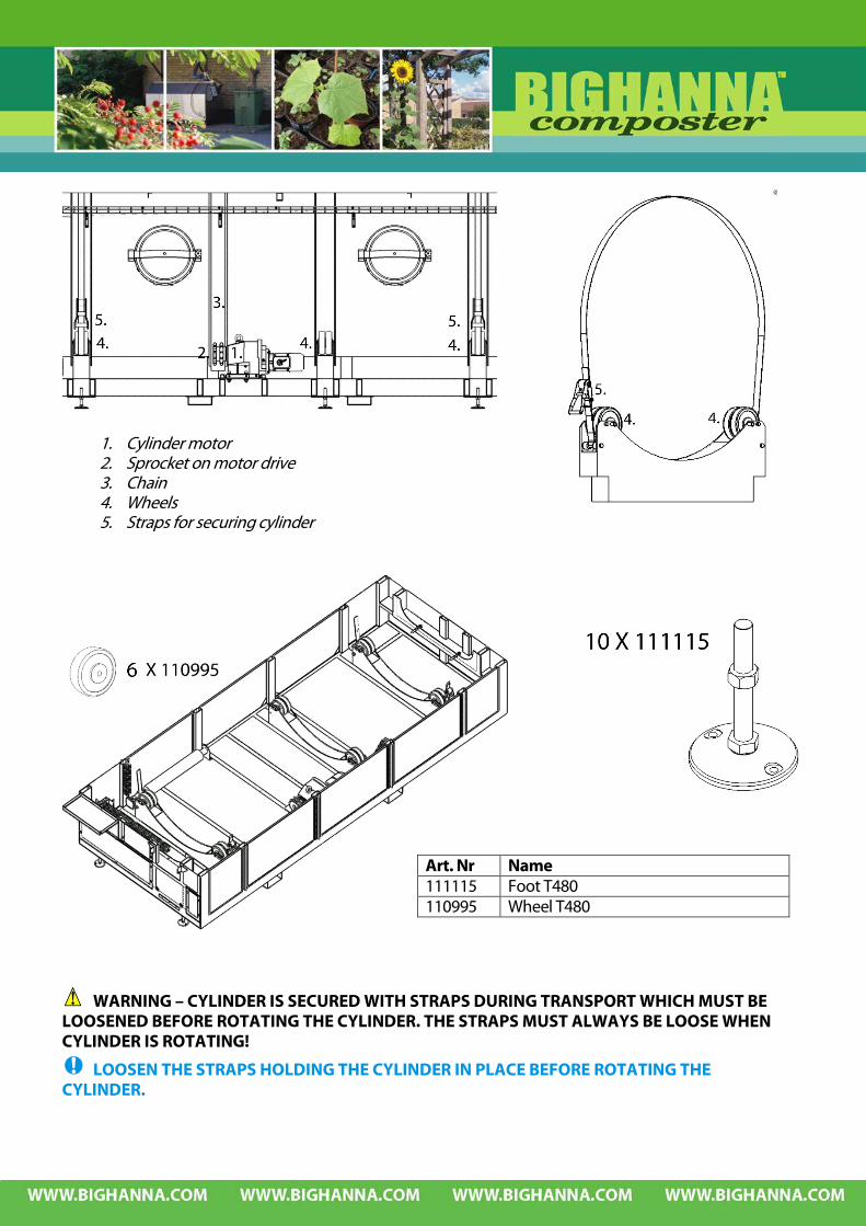
WARNING – CYLINDER IS SECURED WITH STRAPS DURING TRANSPORT WHICH MUST BE LOOSENED BEFORE ROTATING THE CYLINDER. THE STRAPS MUST ALWAYS BE LOOSE WHEN CYLINDER IS ROTATING!
LOOSEN THE STRAPS HOLDING THE CYLINDER IN PLACE BEFORE ROTATING THE CYLINDER.
Art. Nr Name 111115 Foot T480 110995 Wheel T480
1. Cylinder motor 2. Sprocket on motor drive 3. Chain 4. Wheels 5. Straps for securing cylinder

Art. Nr Name 110360 Chain 2 inch duplex rs32b-2 106 links incl lock 110365 32311 MIPAB Sprocket duplex D-2-11, flame hardened tip 110205 Cylinder motor
When filling the cylinder with material for the first time, check the chain wheel on a regular
basis as cylinder is filling up and make sure the chain wheel is well adjusted into the chain. Loosen all 4 bolts and use the adjusting screws to move the motor.
Note that the sprocket is allowed to move axially on the motor shaft in order to follow the chain on the cylinder.
WARNING – MOTOR FOR CYLINDER IS EQUIPPED WITH A BRAKE SECURING THE CYLINDER POSITION. THE CYLINDER WILL MOVE IF THE BRAKE IS DISCONNECTED.THE CYLINDER FILLED WITH MATERIAL HAS CONSIDERABLE WEIGHT AND CAN CAUSE FATAL ACCIDENTS WHEN IT MOVES!
WHEN DOING MAINTENANCE OR SERVICE ON THE MOTOR, CHAIN, CHAIN WHEEL OR INSIDE THE CYLINDER USE THE STRAPS TO SECURE THE CYLINDER POSITION. STRAPS ARE LOCATED UNDER THE CARRIERS FOR THE WHEEL.
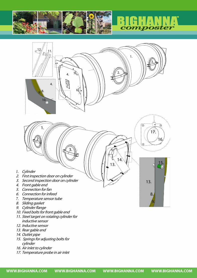
1. Cylinder 2. First inspection door on cylinder 3. Second inspection door on cylinder 4. Front gable end 5. Connection for fan 6. Connection for infeed 7. Temperature sensor tube 8. Sliding gasket 9. Cylinder flange 10. Fixed bolts for front gable end 11. Steel target on rotating cylinder for
inductive sensor 12. Inductive sensor 13. Rear gable end 14. Outlet pipe 15. Springs for adjusting bolts for
cylinder 16. Air inlet to cylinder 17. Temperature probe in air inlet
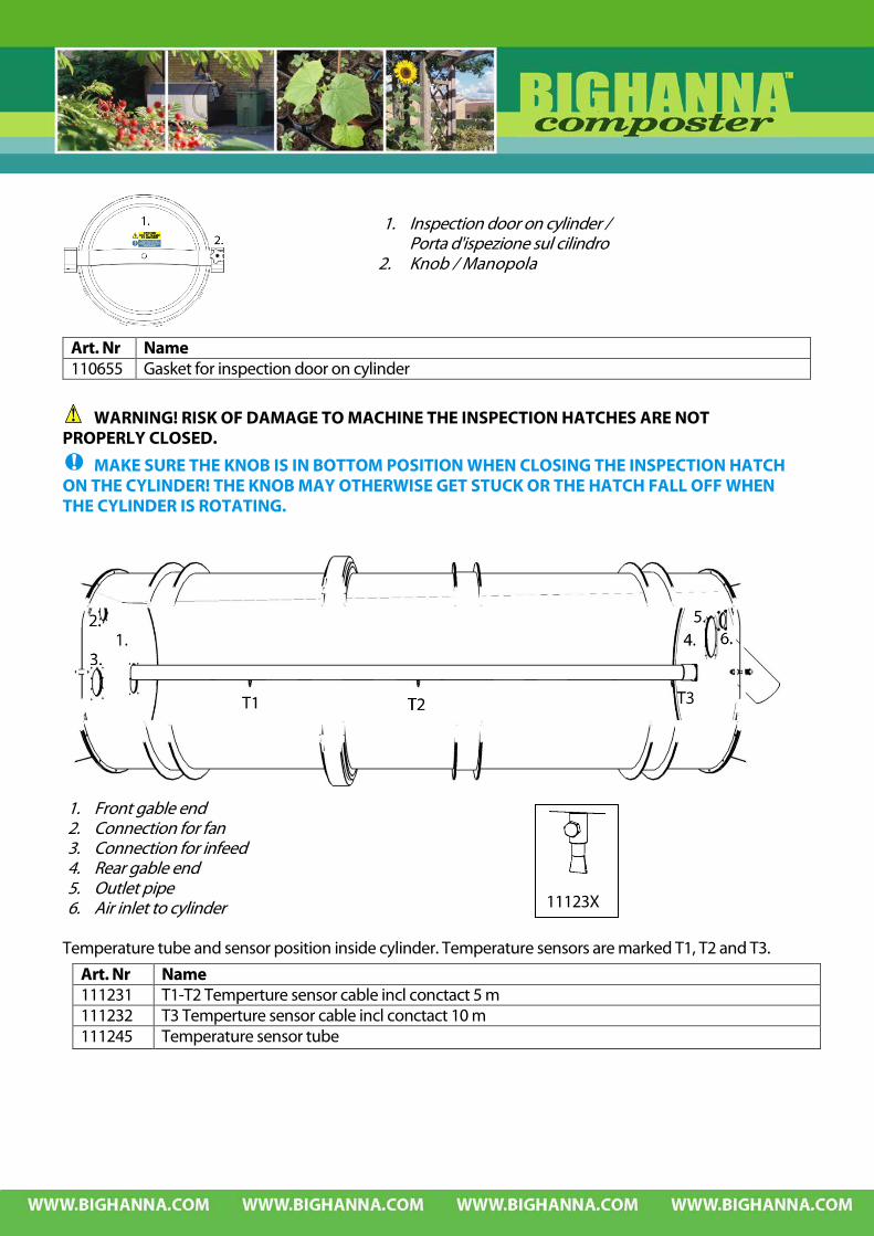
WARNING! RISK OF DAMAGE TO MACHINE THE INSPECTION HATCHES ARE NOT PROPERLY CLOSED.
MAKE SURE THE KNOB IS IN BOTTOM POSITION WHEN CLOSING THE INSPECTION HATCH ON THE CYLINDER! THE KNOB MAY OTHERWISE GET STUCK OR THE HATCH FALL OFF WHEN THE CYLINDER IS ROTATING.
1. Front gable end 2. Connection for fan 3. Connection for infeed 4. Rear gable end 5. Outlet pipe 6. Air inlet to cylinder
Temperature tube and sensor position inside cylinder. Temperature sensors are marked T1, T2 and T3.
Art. Nr Name 110655 Gasket for inspection door on cylinder
11123X
1. Inspection door on cylinder / Porta d'ispezione sul cilindro
2. Knob / Manopola
Art. Nr Name 111231 T1-T2 Temperture sensor cable incl conctact 5 m 111232 T3 Temperture sensor cable incl conctact 10 m 111245 Temperature sensor tube
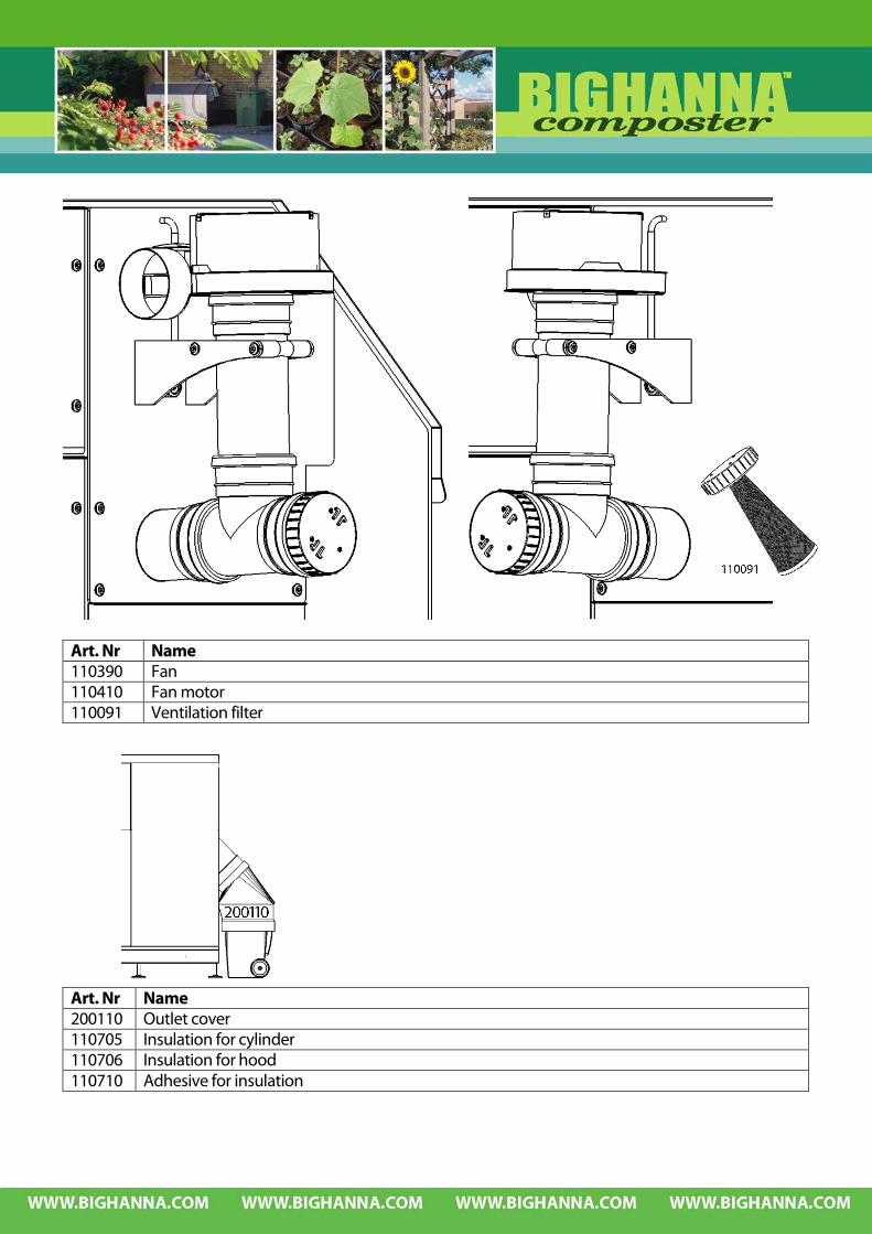
Art. Nr Name 110390 Fan 110410 Fan motor 110091 Ventilation filter
Art. Nr Name 200110 Outlet cover 110705 Insulation for cylinder 110706 Insulation for hood 110710 Adhesive for insulation

Art. Nr Name 110115 In-conveyor 111455 Propeller kit (4 pieces)
1. Infeed hopper lid in opened position 2. 80 litre hopper 3. In-conveyor (110115). 4. Propellers in Polyurethane (111455) 5. Drainage 6. Access point for cleaning. 7. Motor infeed 8. Seal 9. Pipe in to cylinder

Art no Name A Electrical cabinet 110205 Motor cylinder 110250 Motor inconveyor 110410 Motor fan 110131 Safety magnet contact 110141 Safety magnet contact key 110121 Inductive sensor ‘inspection door pos.’ 110125 Emergency stop button 110175 Heater 110231 Temperature sensors 110232 Temperature sensors
See Machine specification for full details on electrical parts.

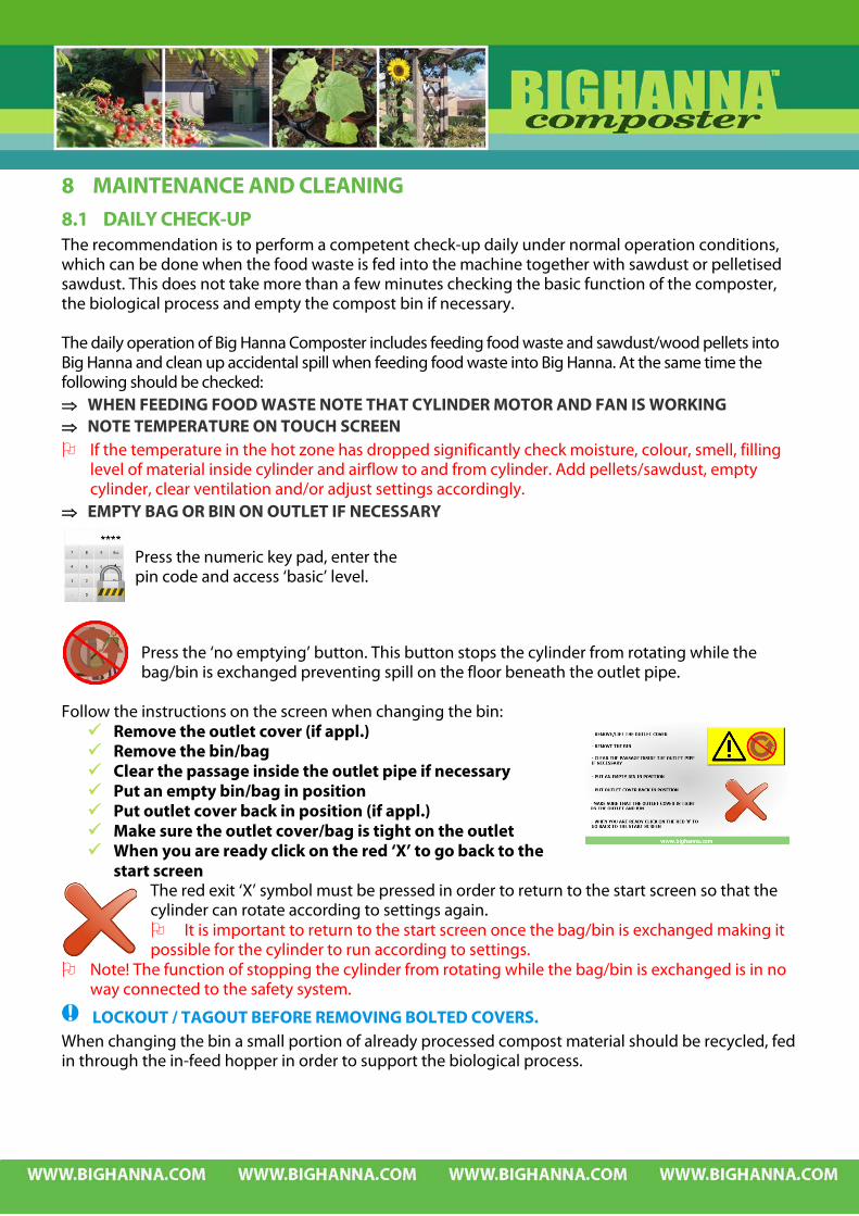
8 MAINTENANCE AND CLEANING 8.1 DAILY CHECK-UP The recommendation is to perform a competent check-up daily under normal operation conditions, which can be done when the food waste is fed into the machine together with sawdust or pelletised sawdust. This does not take more than a few minutes checking the basic function of the composter, the biological process and empty the compost bin if necessary. The daily operation of Big Hanna Composter includes feeding food waste and sawdust/wood pellets into Big Hanna and clean up accidental spill when feeding food waste into Big Hanna. At the same time the following should be checked: ⇒ WHEN FEEDING FOOD WASTE NOTE THAT CYLINDER MOTOR AND FAN IS WORKING ⇒ NOTE TEMPERATURE ON TOUCH SCREEN If the temperature in the hot zone has dropped significantly check moisture, colour, smell, filling
level of material inside cylinder and airflow to and from cylinder. Add pellets/sawdust, empty cylinder, clear ventilation and/or adjust settings accordingly.
⇒ EMPTY BAG OR BIN ON OUTLET IF NECESSARY
Press the ‘no emptying’ button. This button stops the cylinder from rotating while the bag/bin is exchanged preventing spill on the floor beneath the outlet pipe.
Follow the instructions on the screen when changing the bin: Remove the outlet cover (if appl.) Remove the bin/bag Clear the passage inside the outlet pipe if necessary Put an empty bin/bag in position Put outlet cover back in position (if appl.) Make sure the outlet cover/bag is tight on the outlet When you are ready click on the red ‘X’ to go back to the
start screen The red exit ‘X’ symbol must be pressed in order to return to the start screen so that the cylinder can rotate according to settings again. It is important to return to the start screen once the bag/bin is exchanged making it possible for the cylinder to run according to settings.
Note! The function of stopping the cylinder from rotating while the bag/bin is exchanged is in no way connected to the safety system.
LOCKOUT / TAGOUT BEFORE REMOVING BOLTED COVERS. When changing the bin a small portion of already processed compost material should be recycled, fed in through the in-feed hopper in order to support the biological process.
Press the numeric key pad, enter the pin code and access ‘basic’ level.
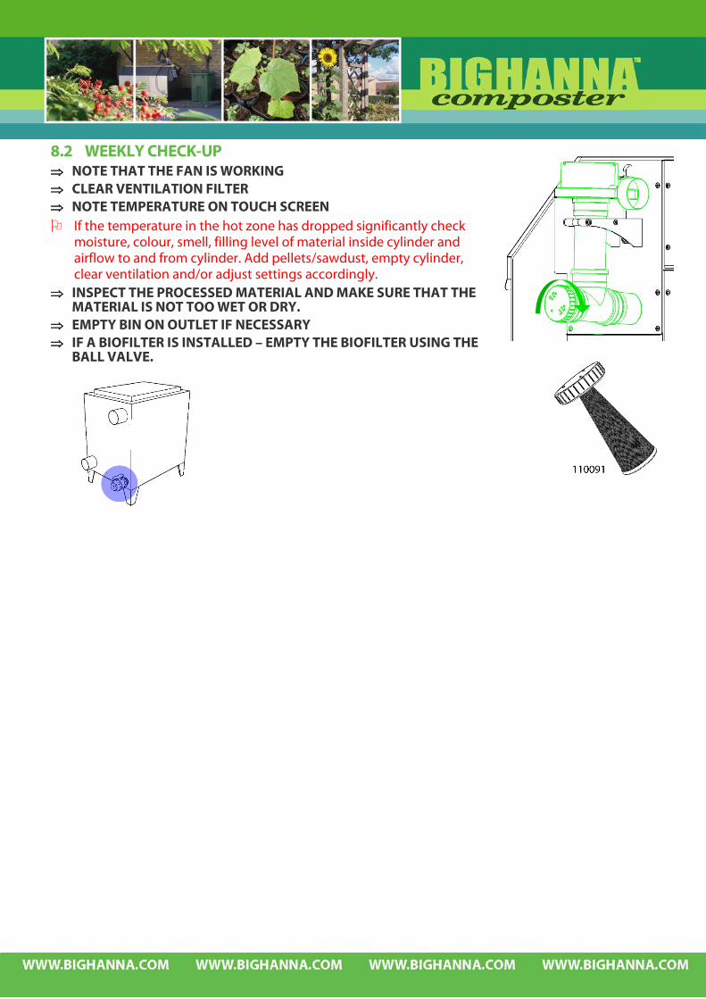
8.2 WEEKLY CHECK-UP ⇒ NOTE THAT THE FAN IS WORKING ⇒ CLEAR VENTILATION FILTER ⇒ NOTE TEMPERATURE ON TOUCH SCREEN If the temperature in the hot zone has dropped significantly check
moisture, colour, smell, filling level of material inside cylinder and airflow to and from cylinder. Add pellets/sawdust, empty cylinder, clear ventilation and/or adjust settings accordingly.
⇒ INSPECT THE PROCESSED MATERIAL AND MAKE SURE THAT THE MATERIAL IS NOT TOO WET OR DRY.
⇒ EMPTY BIN ON OUTLET IF NECESSARY ⇒ IF A BIOFILTER IS INSTALLED – EMPTY THE BIOFILTER USING THE
BALL VALVE.

8.2.1 CHECK-UP MONTHLY – CLEAN THE HEATER ⇒ CLEAN THE HEATER: Open the inspection door on the left side of the machine. Remove any material on the floor under the heater. Use a moist cloth cleaning the heater. Never use detergents or solvent-based products.

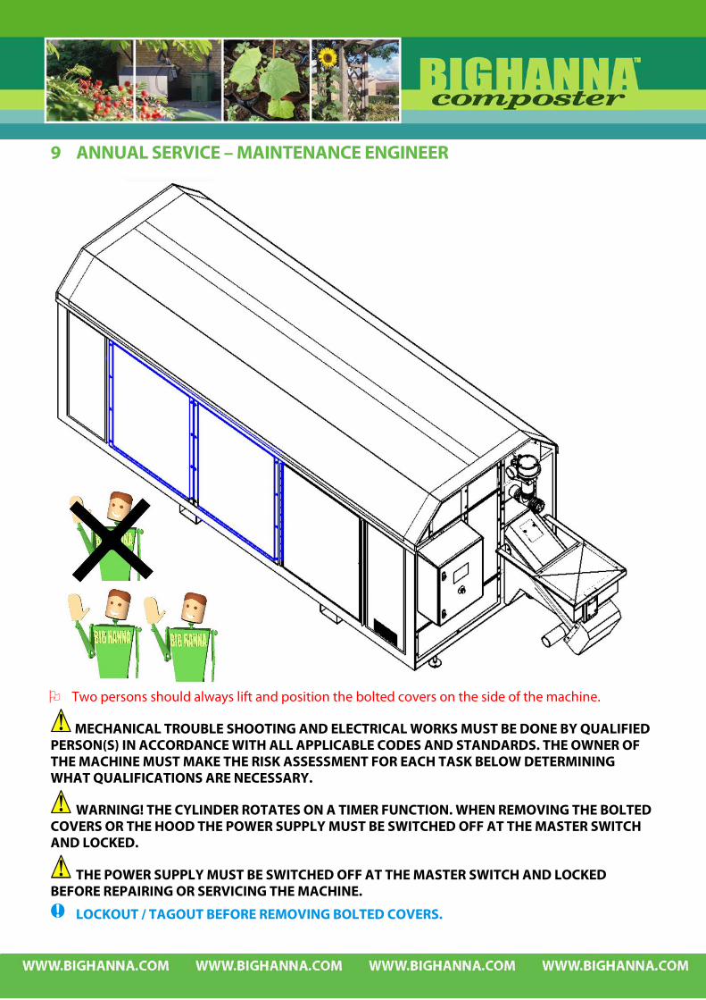
9 ANNUAL SERVICE – MAINTENANCE ENGINEER
Two persons should always lift and position the bolted covers on the side of the machine.
MECHANICAL TROUBLE SHOOTING AND ELECTRICAL WORKS MUST BE DONE BY QUALIFIED PERSON(S) IN ACCORDANCE WITH ALL APPLICABLE CODES AND STANDARDS. THE OWNER OF THE MACHINE MUST MAKE THE RISK ASSESSMENT FOR EACH TASK BELOW DETERMINING WHAT QUALIFICATIONS ARE NECESSARY.
WARNING! THE CYLINDER ROTATES ON A TIMER FUNCTION. WHEN REMOVING THE BOLTED COVERS OR THE HOOD THE POWER SUPPLY MUST BE SWITCHED OFF AT THE MASTER SWITCH AND LOCKED.
THE POWER SUPPLY MUST BE SWITCHED OFF AT THE MASTER SWITCH AND LOCKED BEFORE REPAIRING OR SERVICING THE MACHINE.
LOCKOUT / TAGOUT BEFORE REMOVING BOLTED COVERS.

9.1 ANNUAL SERVICE CHECK LIST Check function of emergency stop and safety switches on all doors. Check all warning labels Clean ventilation pipes to fan. Change ventilation filter if worn. Test function of heater and inspect for wear. Check, clean and grease chain and sprockets. Replace sprocket if worn. Inspect the wheels for wear, replace if worn. Check that machine is levelled. Inspect both front and back end of the cylinder, adjust ends if necessary. Change seals on inspection doors if worn. Check propellers, replace if worn. Check the threads on the knob on the inspection doors. Check motors in accordance to separate manual.

9.2 SERVICE CHECK LIST IN DETAILS 9.2.1 CHECK FUNCTION OF EMERGENCY STOP AND SAFETY SWITCHES ON ALL DOORS.
The infeed hopper lid is equipped with a magnetic limit switch connected to a safety plc; when the lid is lifted the in conveyor stops. All four inspection doors on the hood are equipped with a magnetic limit switch connected to a safety plc; when the doors are opened all motors are stopped. There are two Emergency Stop buttons connected to a safety plc, one at the front and on at the back. When an emergency stop button is pressed all motors are stopped. The magnetic limit switch has one closing and one opening contact. The contacts are monitored by a safety plc. To avoid unauthorised operation of the switch it is only possible to actuate the switch with a coded magnet. Other magnets, screwdrivers and tools have no affect on the switch contacts.
9.2.2 WARNING – INFEED HOPPER LID When the infeed hopper lid is opened there is a small warning sign flashing on the touch screen. When the lid is closed this warning sign disappears. There is no need to reset the machine after opening and closing the infeed hopper lid.

9.2.3 INSPECTION DOOR(S) OPEN When any of the inspection door(s) on the hood is opened there is a small warning sign flashing on the touch screen. Close the inspection doors. When the doors are locked, reset the machine using the reset button.
9.2.4 EMERGENCY STOP When an emergency stop button is pressed there is a text appearing on the touch screen with an instruction that should be followed: ‘Warning! Emergency Stop active. Twist to release the Emergency Stop button and reset the machine on the reset button.’
9.2.5 CHECK ALL WARNING LABELS Replace warning labels if worn.
On front of machine At each motor
On each inspection hatch At cylinder motor

9.2.6 CLEAN VENTILATION PIPES TO FAN. Clean all piping leading from front end to the fan.
9.2.7 CHANGE VENTILATION FILTER IF WORN. Change ventilation filter if worn. Article no 110091.
9.2.8 TEST FUNCTION OF HEATER AND INSPECT FOR WEAR. Heater is positioned in the front end under the hood. Replace if worn.
9.2.9 INSPECT THE WHEELS FOR WEAR.
LOCKOUT AND TAGOUT BEFORE REMOVING BOLTED COVERS. Check wheels for wear and replace if necessary. The wheels can be accessed from the inspection doors on and by removing one of the bolted covers on the left side.
Two persons should always lift and position the bolted covers on the side of the machine. Note! The bolted cover in the middle does not need to be removed in order to inspect the wheels.
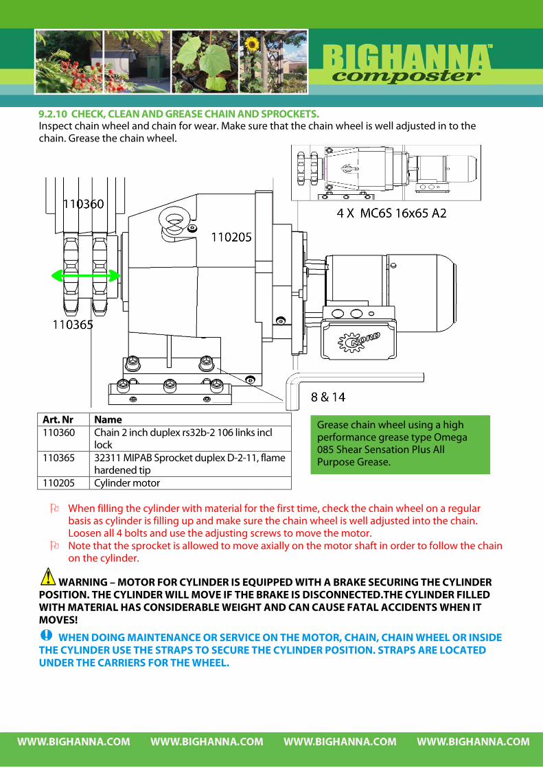
9.2.10 CHECK, CLEAN AND GREASE CHAIN AND SPROCKETS. Inspect chain wheel and chain for wear. Make sure that the chain wheel is well adjusted in to the chain. Grease the chain wheel.
Art. Nr Name 110360 Chain 2 inch duplex rs32b-2 106 links incl
lock 110365 32311 MIPAB Sprocket duplex D-2-11, flame
hardened tip 110205 Cylinder motor
When filling the cylinder with material for the first time, check the chain wheel on a regular
basis as cylinder is filling up and make sure the chain wheel is well adjusted into the chain. Loosen all 4 bolts and use the adjusting screws to move the motor.
Note that the sprocket is allowed to move axially on the motor shaft in order to follow the chain on the cylinder.
WARNING – MOTOR FOR CYLINDER IS EQUIPPED WITH A BRAKE SECURING THE CYLINDER POSITION. THE CYLINDER WILL MOVE IF THE BRAKE IS DISCONNECTED.THE CYLINDER FILLED WITH MATERIAL HAS CONSIDERABLE WEIGHT AND CAN CAUSE FATAL ACCIDENTS WHEN IT MOVES!
WHEN DOING MAINTENANCE OR SERVICE ON THE MOTOR, CHAIN, CHAIN WHEEL OR INSIDE THE CYLINDER USE THE STRAPS TO SECURE THE CYLINDER POSITION. STRAPS ARE LOCATED UNDER THE CARRIERS FOR THE WHEEL.
Grease chain wheel using a high performance grease type Omega 085 Shear Sensation Plus All Purpose Grease.
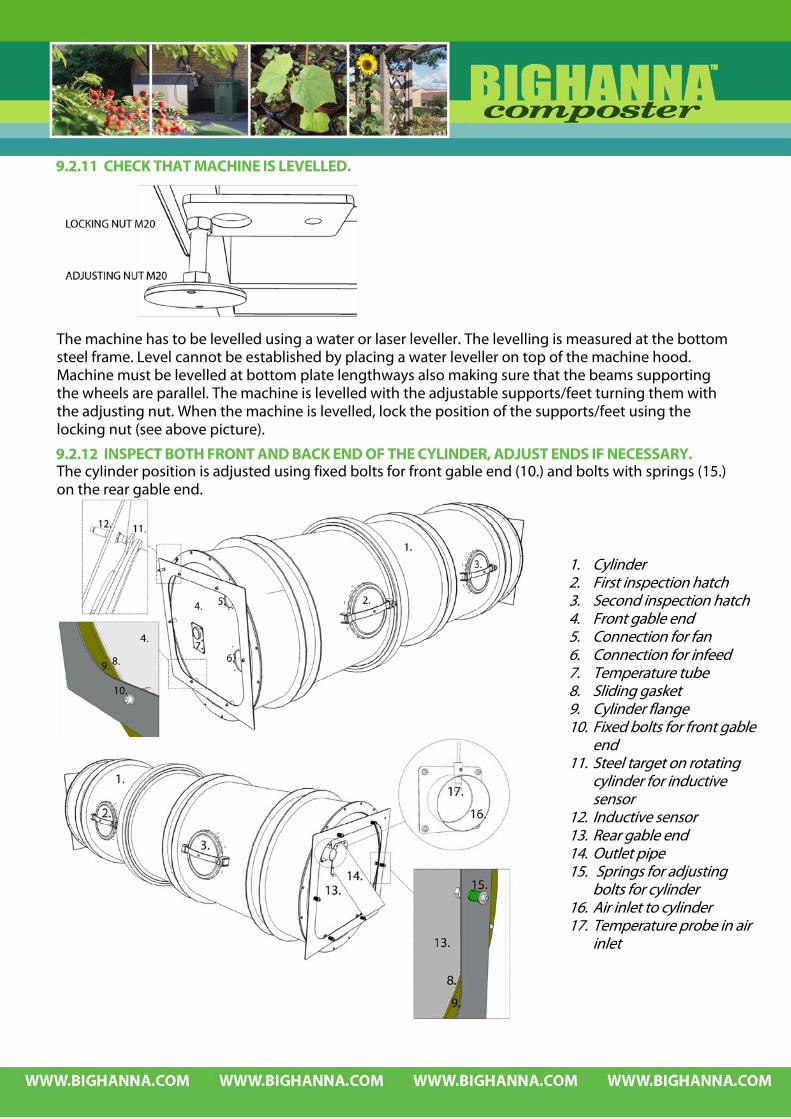
9.2.11 CHECK THAT MACHINE IS LEVELLED.
The machine has to be levelled using a water or laser leveller. The levelling is measured at the bottom steel frame. Level cannot be established by placing a water leveller on top of the machine hood. Machine must be levelled at bottom plate lengthways also making sure that the beams supporting the wheels are parallel. The machine is levelled with the adjustable supports/feet turning them with the adjusting nut. When the machine is levelled, lock the position of the supports/feet using the locking nut (see above picture).
9.2.12 INSPECT BOTH FRONT AND BACK END OF THE CYLINDER, ADJUST ENDS IF NECESSARY. The cylinder position is adjusted using fixed bolts for front gable end (10.) and bolts with springs (15.) on the rear gable end.
1. Cylinder 2. First inspection hatch 3. Second inspection hatch 4. Front gable end 5. Connection for fan 6. Connection for infeed 7. Temperature tube 8. Sliding gasket 9. Cylinder flange 10. Fixed bolts for front gable
end 11. Steel target on rotating
cylinder for inductive sensor
12. Inductive sensor 13. Rear gable end 14. Outlet pipe 15. Springs for adjusting
bolts for cylinder 16. Air inlet to cylinder 17. Temperature probe in air
inlet

9.2.13 CHECK PROPELLERS IN THE INFEED HOPPER Replace propellers if worn.
9.2.14 CHECK SEALS ON INSPECTION DOORS AND INLET HOPPER Replace seals if worn.
9.2.15 CHECK THE THREADS ON THE KNOB ON THE INSPECTION DOORS Replace the knob if worn.
9.2.16 CHECK MOTORS IN ACCORDANCE TO SEPARATE MANUAL. Motors are specified in machine specification.

10 TROUBLE SHOOTING – MACHINERY
MECHANICAL TROUBLE SHOOTING AND ELECTRICAL WORKS MUST BE DONE BY QUALIFIED PERSON(S) IN ACCORDANCE WITH ALL APPLICABLE CODES AND STANDARDS. THE OWNER OF THE MACHINE MUST MAKE THE RISK ASSESSMENT FOR EACH TASK BELOW DETERMINING WHAT QUALIFICATIONS ARE NECESSARY.
WARNING! THE CYLINDER ROTATES ON A TIMER FUNCTION. WHEN REMOVING THE BOLTED COVERS OR THE HOOD THE POWER SUPPLY MUST BE SWITCHED OFF AT THE MASTER SWITCH AND LOCKED.
THE POWER SUPPLY MUST BE SWITCHED OFF AT THE MASTER SWITCH AND LOCKED BEFORE REPAIRING OR SERVICING THE MACHINE.
LOCKOUT/TAGOUT BEFORE REMOVING BOLTED COVERS. Most problems or fault occurring are about the biological process in the cylinder. If there is a problem with the machinery it almost every time results in problem with the biological process and therefore it is very important to quickly define the problem and repair the composter. Note! Resetting the alarm in the Operator panel only resets the Operator panel, making it possible
to adjust settings, using manual mode etc. It does not reset the fuse and does solve the actual problem. This has to be done for each fuse/fault respectively in the electrical cabinet. If the fault has not been taken care of, the alarm text will re-appear after a set time (default time is 5 minutes) or when trying to run the motor and the fuse trips again.
10.1 INSPECTION DOORS AND EMERGENCY STOP
10.1.1 WARNING – INFEED HOPPER LID When the infeed hopper lid is opened there is a small warning sign flashing on the touch screen. When the lid is closed this warning sign disappears. There is no need to reset the machine after opening and closing the infeed hopper lid.
10.1.2 INSPECTION DOOR(S) OPEN When any of the inspection door(s) on the hood is opened there is a small warning sign flashing on the touch screen. Close the inspection doors. When the doors are locked, reset the machine using the reset button.

10.1.3 EMERGENCY STOP When an emergency stop button is pressed there is a text appearing on the touch screen with an instruction that should be followed: ‘Warning! Emergency Stop active. Twist to release the Emergency Stop button and reset the machine on the reset button.’
10.2 ALARM INDICATOR The Alarm Indicator has the following indications: Flashing red when there is any active,
unacknowledged alarm. Flashing green when no active alarms exist,
but inactive unacknowledged alarms exist. Flashing green when there are only active acknowledged alarms.
10.2.1 ALARM LOG Alarms must be acknowledged using this menu.
Alarm is active. The source of the alarm remains (i.e. fuse is blown) and alarm is not acknowledged in the alarm log menu.
Alarm is inactive. The source of the alarm is solved (i.e. fuse is reset) but the alarm is not acknowledged in the alarm log menu.
Alarm is acknowledged. The source of the alarm remains (i.e. fuse is blown) but alarm is acknowledged in the alarm log.
Alarm is normal. The source of the alarm is solved (i.e. fuse is reset) and the alarm is acknowledged in the alarm log menu.

Note that the Alarm Indicator is positioned in the upper left hand corner of the touch screen by default. The symbol can be moved to any location on the screen by clicking on it, holding and moving it. The Alarm Indicator disappears when all alarms are both acknowledged and have returned to inactive status. Mark an Alarm and Acknowledge Selected or Acknowledge All Alarms using the Alarm Menu. ALARM LOG and alarm indicator
The Alarm Indicator disappears when all alarms are both acknowledged and have returned to inactive status. Mark an Alarm and Acknowledge Selected or Acknowledge All Alarms using the Alarm Menu. The alarms that must be acknowledged are: Emergency stop Cylinder is not rotating according to settings Cylinder motor - fuse tripped Cylinder motor - inverter fault Fan motor – fuse tripped Fan motor – inverter fault In-conveyor has automatically reversed 2 times but is still unable to run Infeed motor - fuse tripped Infeed motor – inverter fault Heater – fuse tripped
10.3 ALARM – CYLINDER IS NOT ROTATING ACCORDING TO SETTINGS More than 10 hours have elapsed since the cylinder rotated: - Inspect sprocket and chain for wear. The chain wheel and chain are easily accessible behind inspection door number 2 on the hood. - Rotate the cylinder using the manual rotation menu - Check the function of the limit switch on the cylinder If this alarm shows up repeatedly - contact service personnel
Note that this ALARM needs to be acknowledged in the ALARM list in order to turn off the Alarm
Indicator which is visible in the left hand upper corner on all screens. Use the ALARM button to go to alarm log menu.
10.3.1 INDUCTIVE SENSOR (110121) FOR INSPECTION DOOR POSITION Normally, the cylinder rotates one full revolution, always returning the inspection doors to the same position which is controlled by the inductive sensor for the inspection door position (110121). This alarm is triggered by the touch screen plc when the cylinder steel target (11 below) has not passed the inductive sensor (12). Therefore, check the function of this sensor, both electrics and mechanics.
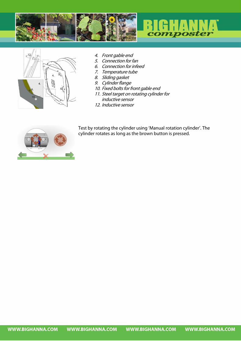
Test by rotating the cylinder using ‘Manual rotation cylinder’. The cylinder rotates as long as the brown button is pressed.
4. Front gable end 5. Connection for fan 6. Connection for infeed 7. Temperature tube 8. Sliding gasket 9. Cylinder flange 10. Fixed bolts for front gable end 11. Steel target on rotating cylinder for
inductive sensor 12. Inductive sensor
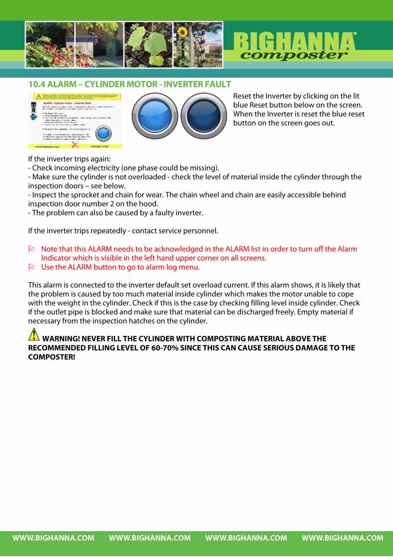
10.4 ALARM – CYLINDER MOTOR - INVERTER FAULT Reset the Inverter by clicking on the lit blue Reset button below on the screen. When the Inverter is reset the blue reset button on the screen goes out.
If the inverter trips again: - Check incoming electricity (one phase could be missing). - Make sure the cylinder is not overloaded - check the level of material inside the cylinder through the inspection doors – see below. - Inspect the sprocket and chain for wear. The chain wheel and chain are easily accessible behind inspection door number 2 on the hood. - The problem can also be caused by a faulty inverter. If the inverter trips repeatedly - contact service personnel. Note that this ALARM needs to be acknowledged in the ALARM list in order to turn off the Alarm
Indicator which is visible in the left hand upper corner on all screens. Use the ALARM button to go to alarm log menu.
This alarm is connected to the inverter default set overload current. If this alarm shows, it is likely that the problem is caused by too much material inside cylinder which makes the motor unable to cope with the weight in the cylinder. Check if this is the case by checking filling level inside cylinder. Check if the outlet pipe is blocked and make sure that material can be discharged freely. Empty material if necessary from the inspection hatches on the cylinder.
WARNING! NEVER FILL THE CYLINDER WITH COMPOSTING MATERIAL ABOVE THE RECOMMENDED FILLING LEVEL OF 60-70% SINCE THIS CAN CAUSE SERIOUS DAMAGE TO THE COMPOSTER!

10.5 ALARM – CYLINDER MOTOR - FUSE OR RELAY TRIPPED Reset the fuse/relay inside the electrical cabinet. - Check incoming electricity (one phase could be missing). - Make sure the cylinder is not overloaded - check the level of material inside the cylinder through the inspection doors – see below. - Inspect the sprocket and chain for wear. See 9.2.10 - Problem can also be caused by a faulty Inverter. If the fuse trips repeatedly - contact service personnel. Note that this ALARM needs to be acknowledged in the ALARM list
in order to turn off the Alarm Indicator which is visible in the left hand upper corner on all screens.
Use the ALARM button to go to alarm log menu. When the thermal relay or fuse for the cylinder motor has tripped, the problem may have been be caused by too much material inside cylinder which makes the motor unable to cope with the weight in the cylinder. Check if this is the case by checking filling level inside cylinder. Check if the outlet pipe is blocked and make sure that material can be discharged freely. If necessary, empty material from the inspection hatches on the cylinder.
WARNING! NEVER FILL THE CYLINDER WITH COMPOSTING MATERIAL ABOVE THE RECOMMENDED FILLING LEVEL OF 60-70% SINCE THIS CAN CAUSE SERIOUS DAMAGE TO THE COMPOSTER!

10.6 ALARM – FAN MOTOR – INVERTER FAULT Reset the Inverter by clicking on the lit blue Reset button below on the screen. When the Inverter is reset the blue reset button on the screen goes out.
If the inverter trips again: - Problem can be caused by dirt and dust in the fan and the ventilation pipes see below. - Turn off electricity before cleaning pipes and the fan - Problem can also be caused by a faulty Inverter. If the inverter trips repeatedly - contact service personnel. Note that this ALARM needs to be acknowledged in the ALARM list in order to turn off the Alarm
Indicator which is visible in the left hand upper corner on all screens. Use the ALARM button to go to alarm log menu.
LOCKOUT/TAGOUT BEFORE REMOVING BOLTED COVERS. The fan is the “lungs” of the Big Hanna – if the biological process does not get the right amount of oxygen, the result will be bad smell. Pay attention to if the fan is vibrating or making a noise. Check the ventilation pipes and clean if necessary.
10.7 ALARM – FAN MOTOR – FUSE TRIPPED Reset the fuse inside the electrical cabinet. - Problem can be caused by dirt and dust in the fan and the ventilation pipes see below. - Turn off electricity before cleaning pipes and the fan. - Problem can also be caused by a faulty Inverter. If the fuse trips repeatedly - contact service personnel.
Note that this ALARM needs to be acknowledged in the ALARM list in order to turn off the Alarm Indicator which is visible in the left hand upper corner on all screens.
Use the ALARM button to go to alarm log menu.
LOCKOU/TAGOUT BEFORE REMOVING BOLTED COVERS. The fan is the “lungs” of the Big Hanna – if the biological process does not get the right amount of oxygen, the result will be bad smell. Pay attention to if the fan is vibrating or making a noise. Check the ventilation pipes and clean if necessary – see 0.
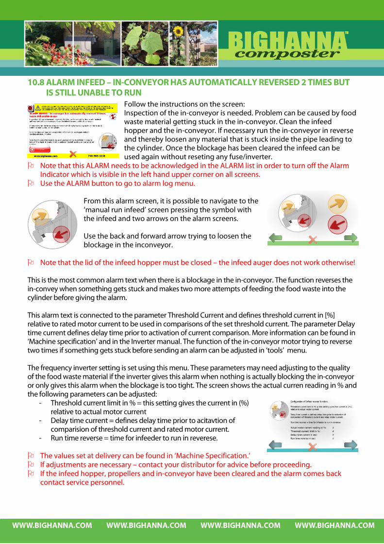
10.8 ALARM INFEED – IN-CONVEYOR HAS AUTOMATICALLY REVERSED 2 TIMES BUT IS STILL UNABLE TO RUN
Follow the instructions on the screen: Inspection of the in-conveyor is needed. Problem can be caused by food waste material getting stuck in the in-conveyor. Clean the infeed hopper and the in-conveyor. If necessary run the in-conveyor in reverse and thereby loosen any material that is stuck inside the pipe leading to the cylinder. Once the blockage has been cleared the infeed can be used again without reseting any fuse/inverter.
Note that this ALARM needs to be acknowledged in the ALARM list in order to turn off the Alarm Indicator which is visible in the left hand upper corner on all screens.
Use the ALARM button to go to alarm log menu.
From this alarm screen, it is possible to navigate to the ‘manual run infeed’ screen pressing the symbol with the infeed and two arrows on the alarm screens. Use the back and forward arrow trying to loosen the blockage in the inconveyor.
Note that the lid of the infeed hopper must be closed – the infeed auger does not work otherwise! This is the most common alarm text when there is a blockage in the in-conveyor. The function reverses the in-convey when something gets stuck and makes two more attempts of feeding the food waste into the cylinder before giving the alarm. This alarm text is connected to the parameter Threshold Current and defines threshold current in [%] relative to rated motor current to be used in comparisons of the set threshold current. The parameter Delay time current defines delay time prior to activation of current comparison. More information can be found in ‘Machine specification’ and in the Inverter manual. The function of the in-conveyor motor trying to reverse two times if something gets stuck before sending an alarm can be adjusted in ‘tools’ menu. The frequency inverter setting is set using this menu. These parameters may need adjusting to the quality of the food waste material if the inverter gives this alarm when nothing is actually blocking the in-conveyor or only gives this alarm when the blockage is too tight. The screen shows the actual curren reading in % and the following parameters can be adjusted:
- Threshold current limit in % = this setting gives the current in (%) relative to actual motor current
- Delay time current = defines delay time prior to acitavtion of comparision of threshold current and rated motor current.
- Run time reverse = time for infeeder to run in reverese. The values set at delivery can be found in ‘Machine Specification.’ If adjustments are necessary – contact your distributor for advice before proceeding. If the infeed hopper, propellers and in-conveyor have been cleared and the alarm comes back
contact service personnel.

10.9 ALARM INFEED – INFEED MOTOR – INVERTER FAULT Reset the inverter by clicking on the lit blue Reset button below on the screen. When the Inverter is reset the blue reset button goes out.
Follow the instructions on the screen: - Inspection of the in-conveyor is needed. - Problem can be caused by food waste material getting stuck in the in-conveyor. - Clean the infeed hopper and the in-conveyor. - If necessary run the in-conveyor in reverse and thereby loosen any material that is stuck inside the
pipe leading to the cylinder. - Problem can also be caused by a faulty inverter.
Note that this ALARM needs to be acknowledged in the ALARM list in order to turn off the Alarm
Indicator which is visible in the left hand upper corner on all screens. Use the ALARM button to go to alarm log menu.
From this alarm screen, it is possible to navigate to the ‘manual run infeed’ screen pressing the symbol with the infeed and two arrows on the alarm screens. Use the back and forward arrow trying to loosen the blockage in the inconveyor.
Normally if there is a blockage of the infeed, the alarm that goes off is the ‘ALARM infeed - In-conveyor has automatically reversed 2 times but is still unable to run’ see 10.8. If there is an alarm that the inverter for the infeed motor has tripped the settings of the function of the infeed reversing two times may need adjusting, see above. If the infeed hopper, propellers and in-conveyor have been cleared and the alarm comes back
contact service personnel. If the inverter trips repeatedly – contact service personnel.
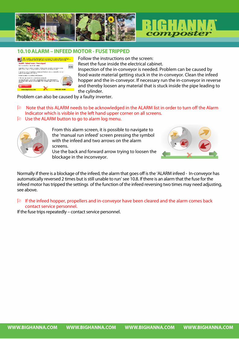
10.10 ALARM – INFEED MOTOR - FUSE TRIPPED Follow the instructions on the screen: Reset the fuse inside the electrical cabinet. Inspection of the in-conveyor is needed. Problem can be caused by food waste material getting stuck in the in-conveyor. Clean the infeed hopper and the in-conveyor. If necessary run the in-conveyor in reverse and thereby loosen any material that is stuck inside the pipe leading to the cylinder.
Problem can also be caused by a faulty inverter. Note that this ALARM needs to be acknowledged in the ALARM list in order to turn off the Alarm
Indicator which is visible in the left hand upper corner on all screens. Use the ALARM button to go to alarm log menu.
From this alarm screen, it is possible to navigate to the ‘manual run infeed’ screen pressing the symbol with the infeed and two arrows on the alarm screens. Use the back and forward arrow trying to loosen the blockage in the inconveyor.
Normally if there is a blockage of the infeed, the alarm that goes off is the ‘ALARM infeed - In-conveyor has automatically reversed 2 times but is still unable to run’ see 10.8. If there is an alarm that the fuse for the infeed motor has tripped the settings of the function of the infeed reversing two times may need adjusting, see above. If the infeed hopper, propellers and in-conveyor have been cleared and the alarm comes back
contact service personnel. If the fuse trips repeatedly – contact service personnel.

10.11 FUSE FOR HEATER TRIPPED Follow the instructions on the screen: Reset fuse in electrical cabinet. Dismantle the front panel and inspect the heater. If there is any damage on the heater or the fuse trips repeatedly contact service personnel or order a replacement heater.
Note that this ALARM needs to be acknowledged in the ALARM list in order to turn off the Alarm Indicator which is visible in the left hand upper corner on all screens.
Use the ALARM button to go to alarm log menu.
10.12 CHANGING WHEELS
WARNING – MOTOR FOR CYLINDER IS EQUIPPED WITH A BRAKE SECURING THE CYLINDER POSITION. THE CYLINDER WILL MOVE IF THE BRAKE IS DISCONNECTED.THE CYLINDER FILLED WITH MATERIAL HAS A CONSIDERABLE WEIGHT AND CAN CAUSE FATAL ACCIDENTS WHEN IT MOVES! Balance the material inside the cylinder before replacing a wheel and make sure that the cylinder
is supported and will not tilt when the wheel is removed.
The condition of the wheels needs to be checked every year for wear and replaced if necessary.
Place support under the cylinder allowing the wheel to be removed without the cylinder tilting.
Loosen the nyloc nut from the axle. Push the axle/bolt from its position and
remove the wheel. Replace the wheel and axle/bolt.