operation and maintenance of the mcv100 and … · operation and maintenance of the ... ventilator...
TRANSCRIPT

Operation and Maintenance of the MCV100 and MCV100-B
Portable Ventilator
1

Applications of the MCV100(B)
• The MCV100 and MCV100-B Mass Casualty Ventilators are electronically controlled portable ventilators, designed to provide emergency respiratory support by means of a face mask or an endotracheal tube inserted into a patient’s airway.
• The MCV100 and MCV100-B differ only in that the MCV100-B offers a 60% air mix source gas selection. All other features and functionality is the same. Within this presentation, we will refer to the ventilators collectively as MCV100(B), meaning the MCV100 and MCV100-B
• The MCV100(B) are volume controlled ventilators that deliver timed-cycled constant flow breaths.
• The MCV100(B) are all-weather ventilators suitable for use at the scene of a medical incident, as well as in pre-hospital, intra-hospital, and inter-hospital transport.
• The MCV100(B) have been designed to withstand direct exposure to rain, up to 100G shock and vibration, and drops of up to 1 meter.
• These ventilators are intended for use on patients weighing greater than 20kg, or 44 lbs.
2

Overview of Controls and Settings
3

Ventilator ConnectionsPatient Circuit Connection
• To attach the breathing circuit, press the open end of a three-foot circuit with one-way valve firmly onto the 22 mm patient circuit connection.
• The circuit connection will accommodate any standard 22 mm internal diameter ventilation circuit with one way valve, although the MCV100(B) has been tested and approved using the Allied three-foot breathing circuits with one-way valve.
4

Ventilator ConnectionsPatient Circuits
• Allied offers several affordable three-foot circuit configurations to meet the caregiver’s requirements.
• All circuits contain three feet of corrugated tubing, a one-way duck-bill valve, and a swivel connector capable of accepting a mask or an ET tube.
• Optional configurations incorporate a pre-packaged cuffed mask and/or a bacterial exhalation filter.
• The following part numbers represent the various pre-packaged configurations and accessory items offered.
Three-Foot Circuit Configurations for EPV100 Portable Ventilator
Allied Part # Case Quantity
L599-140 3 foot circuit, One Way Valve, Swivel Connnector, Adult Cuffed Mask, Exhalation Filter 10
L599-190 3 foot circuit, One Way Valve, Swivel Connnector, Exhalation Filter (No Mask) 10
L599-130 3 foot circuit, One Way Valve, Swivel Connnector, Adult Cuffed Mask (No Filter) 10
L599-180 3 foot circuit, One Way Valve, Swivel Connnector (No Mask or Filter) 10
Circuit Accessories Available From Aliied Healthcare Products, Inc.
Allied Part # Case Quantity
LPEEP Adjustable PEEP Valve, 0-20cm H2O 12
L599-200 Exhalation filter 10
L595161-10 Adult Oxygen Mask 10
L595162-10 Child Oxygen Mask 10
5

Patient Circuit ConnectionsOverview of Allied Patient Circuit Connections
6
Patient Circuit ConnectionsFitting of PEEP Valve and Mask or ET Tubes
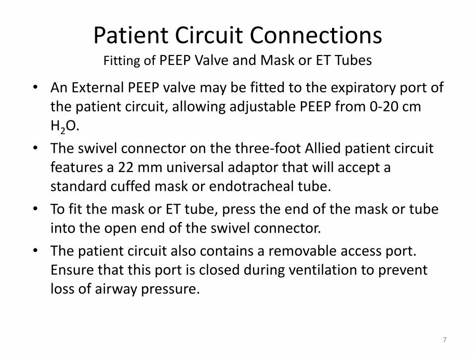
• An External PEEP valve may be fitted to the expiratory port of the patient circuit, allowing adjustable PEEP from 0-20 cm H2O.
• The swivel connector on the three-foot Allied patient circuit features a 22 mm universal adaptor that will accept a standard cuffed mask or endotracheal tube.
• To fit the mask or ET tube, press the end of the mask or tube into the open end of the swivel connector.
• The patient circuit also contains a removable access port. Ensure that this port is closed during ventilation to prevent loss of airway pressure.
7
Ventilator ConnectionsOxygen Connection (if O2 is available)
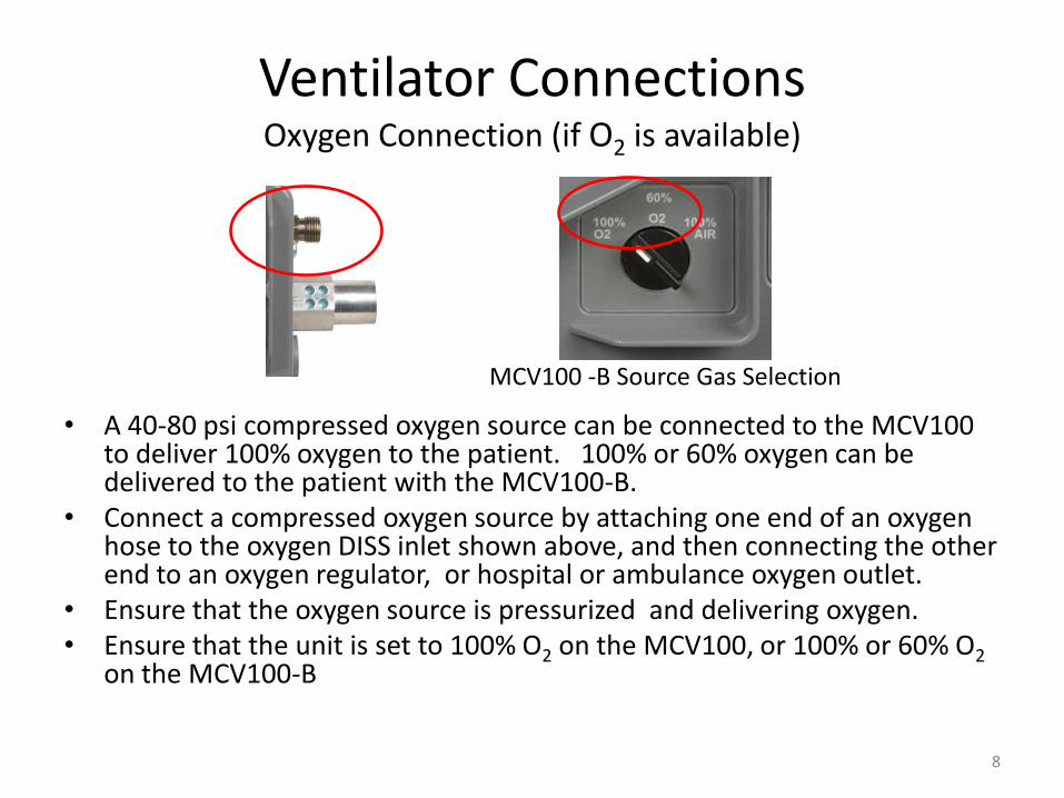
• A 40-80 psi compressed oxygen source can be connected to the MCV100 to deliver 100% oxygen to the patient. 100% or 60% oxygen can be delivered to the patient with the MCV100-B.
• Connect a compressed oxygen source by attaching one end of an oxygen hose to the oxygen DISS inlet shown above, and then connecting the other end to an oxygen regulator, or hospital or ambulance oxygen outlet.
• Ensure that the oxygen source is pressurized and delivering oxygen. • Ensure that the unit is set to 100% O2 on the MCV100, or 100% or 60% O2
on the MCV100-B
MCV100 -B Source Gas Selection
8

Controls and SettingsBreaths Per Minute Adjustment
• Adjustable from 8-20 Breaths Per Minute• Adjust with BPM knob and verify setting on LCD display• Recommended AHA guidelines for ventilation
– Adult: 8-12 BPM– Child: 12-20 BPM
9

Controls and SettingsTidal Volume Adjustment
• Adjustable from 200-1200 ml in 10 ml increments
• Adjust with Tidal Volume knob and verify setting on LCD display
• Approximate Tidal Volume settings at 10ml/KgTidal Volume (ml) 200 300 400 500 600 700 800 900 1000 1100 1200
Ideal Body Weight (Kg) 20 30 40 50 60 70 80 90 100 110 120
Ideal Body Weight (lbs.) 44 66 88 110 132 154 176 198 220 242 264 10
Controls and SettingsInspiratory Time
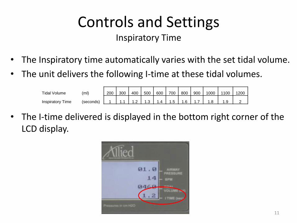
• The Inspiratory time automatically varies with the set tidal volume.
• The unit delivers the following I-time at these tidal volumes.
• The I-time delivered is displayed in the bottom right corner of the LCD display.
Tidal Volume (ml) 200 300 400 500 600 700 800 900 1000 1100 1200
Inspiratory Time (seconds) 1 1.1 1.2 1.3 1.4 1.5 1.6 1.7 1.8 1.9 2
11

Controls and SettingsSource Gas Selection: MCV100
• The MCV100 has source gas selections of 100% O2 or 100% air.
• The 100% air selection should be used when no compressed oxygen source is available.
• The 100% air setting will utilize the internal compressors to ventilate using ambient air drawn in through the air intake or 40mm NATO filter (if equipped).
• The 100% O2 selection should be used if the ventilator has been supplied with compressed gas at 40-80PSI from portable oxygen cylinders, Ambulance oxygen outlets, or hospital oxygen outlets
• If 100% O2 (or 60% O2 MCV100-B)is selected and the supplied source gas should run low, the LCD will display an O2 Low alarm. If after 1 minute the supplied source gas pressure is still low, the MCV100 will automatically begin to ventilate using ambient air..
• Once a sufficient compressed gas source is restored, the MCV100 will revert back to supplying 100% O2.
MCV100 Source Gas Selection12

Controls and SettingsSource Gas Selection: MCV100-B
• The MCV100-B has source gas selections of 100% O2, 100% air, or the 60% O2 air mix feature.
• The 100% O2 and 100% air selections function the same as on the MCV100.
• The 60% O2 selection entrains ambient air through a venturi to conserve compressed oxygen by approximately 50%.
• In 60% O2 or 100% O2 mode, the ventilator does not use the internal compressors and battery life is extended to 21 hours under normal ventilation parameters
MCV100-B Source Gas Selection
13

Controls and SettingsAdjustable Airway Pressure Relief
• The MCV100(B) have an effective adjustable airway pressure relief range of between 5 and 60 cm H2O.
• The adjustable airway pressure relief allows the user to limit the maximum airway pressure delivered via an adjustable pop-off valve.
• Note that this is not a direct control of the airway pressure, but rather an upper limit control. Therefore it is adjusted by viewing the current maximum airway pressure on the LCD screen, and adjusting the knob to limit this maximum airway pressure.
• The set maximum airway pressure is dependent on tidal volume; therefore, any change in these settings will alter the maximum airway pressure.
Adjustable Airway Pressure Relief Control
14

Controls and SettingsAdjustable Airway Pressure Relief (continued)
• When the delivered airway pressure is greater than the adjustable airway pressure setting, the pressure relief will be activated and an audible squeak will be emitted from the airway pressure relief valve.
• The initial setting for this control is typically at the 60 cm mark on the face. Note that this will not necessarily yield a 60cm H2O pressure. The 60 mark indicates that the valve will open to prevent airway pressures exceeding 60cm H2O. Under normal ventilation parameters, the actual airway pressure is well below this setting.
• To set the airway pressure relief, attach the circuit to the vent and occlude the end of the circuit with the palm of your hand. Note the maximum airway pressure. Adjust the knob downwards from 60 cm until you reach the desired maximum airway pressure as indicated by the peak airway pressure readout on the LCD.
15

Controls and SettingsManual Breath Button
• The Manual Breath Button is used to provide timed breaths for CPR or for validating ET tube placement.
• When the Manual Breath Button is pressed it delivers one breath at the set tidal volume and inspiratory time.
• The button must be released and pressed again to deliver a second breath
• The ventilator breath timing is reset when the button is pushed
16

Safety Alarms
• The MCV100(B) have the following alarms– High airway pressure
– Low airway pressure
– Low battery (visual only)
– Low Source Gas
• Alarms are signaled audibly and visibly (no audible on low battery).
• When a ventilation alarm is activated a 58 dB audible alarm will sound, the red alarm LED will blink, and the alarm set point value on the LCD will flash.
• Audible alarms can be silenced for 110 seconds by pressing and holding the alarm silence button. Visible alarms cannot be cleared until the source of the alarm is corrected.
58 dB intermittent beep Red blinking alarm LED(press and hold button to silence)
Flashing alarm set points17

Adjustable Safety AlarmsHigh Airway Pressure Alarm
• The High Airway Pressure Alarm is adjustable from 15-80 cm H2O.
• This alarm may be used to monitor a change in the patient’s condition such as fluid collecting in the lungs or a partial obstruction of the airway.
• To adjust this alarm set point, turn the high airway pressure knob to the desired setting as indicated on the LCD.
• This alarm activates when the airway pressure exceeds the high airway pressure alarm setting.
• This alarm is automatically cleared when 12 seconds pass without a high airway pressure being detected.
High Airway Pressure Alarm Setting Alarm set point18

Adjustable Safety AlarmsLow Airway Pressure Alarm
• The Low Airway Pressure Alarm is adjustable from 0-30 cm H2O.
• To adjust this alarm set point, turn the high airway pressure knob to the desired setting as indicated on the LCD.
• This alarm activates when the airway pressure does not rise above the low airway pressure alarm setting for 15 seconds.
• The alarm will clear when the airway pressure rises above the low airway pressure setting.
Low Airway Pressure Alarm Setting Alarm set point19

Non-Adjustable Safety AlarmsLow Battery Alarm
• The MCV100(B) provide charge status via a battery meter located in the bottom left of the LCD screen, as well as a color indicator LED above the power button.
• When the MCV100(B) are partially discharged and there is less than one hour of power remaining, the battery meter will read mostly empty and the battery LED will change from green to red.
• When the battery becomes critically low, the empty battery meter will flash and the battery LED will start to flash red.
• At this point you must seek backup power immediately to avoid unit shut down!
Battery Meter Battery Charge LED
Green = OK
Solid Red = Low
Flashing Red = Critically Low
20

Non-Adjustable Safety AlarmsLow Source Gas Alarm
• The MCV100(B) contains a low source gas alarm that activates when 100% (or 60% O2 MCV100-B) is selected and the connected high pressure oxygen source falls to or below 40 psi.
• The alarm will flash the text “O2 Low” at the bottom of the screen, the audible alarm will sound, and the alarm LED will blink.
• If 100% or 60% O2 is selected and the pressure falls below 38 psi, the unit will stop delivering breaths.
• After 60 seconds the unit will default to ambient air delivery via the compressors, even though the unit may still be set to 100% or 60% O2.
• The alarm status will clear when the source gas is switched to 100% air, or high pressure oxygen is replenished.
Low O2 Indicator21
Spontaneous BreathingAssist Control Function
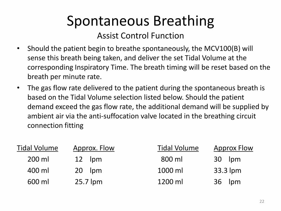
• Should the patient begin to breathe spontaneously, the MCV100(B) will sense this breath being taken, and deliver the set Tidal Volume at the corresponding Inspiratory Time. The breath timing will be reset based on the breath per minute rate.
• The gas flow rate delivered to the patient during the spontaneous breath is based on the Tidal Volume selection listed below. Should the patient demand exceed the gas flow rate, the additional demand will be supplied by ambient air via the anti-suffocation valve located in the breathing circuit connection fitting
Tidal Volume Approx. Flow Tidal Volume Approx Flow
200 ml 12 lpm 800 ml 30 lpm
400 ml 20 lpm 1000 ml 33.3 lpm
600 ml 25.7 lpm 1200 ml 36 lpm
22

Spontaneous BreathingAnti-Suffocation Valve
• The MCV100(B) are equipped with an anti-suffocation valve that will allow the patient to draw in ambient air during a spontaneous breath should the demand exceed that delivered via the assist control .
• Do not occlude this valve during operation.
Anti-suffocation valve
23

CBRN Hazardous Environment Filter
• The air inlet fitting has a NATO standard internal 40 mm thread for attachment of respiratory protective devices.
• Any 40 mm threaded filter that is in compliance with NIOSH-42 CFR Part 84 can be attached to this port to ensure safe ventilation in a toxic environment.
• Ensure that the filter to be installed is capable of providing at least 40 lpm flow to prevent any decrease in performance of the ventilator.
• To install the air Inlet filter, remove the dust cap by prying it at the edge with a fingernail or sharp object, remove the foam insert, and screw in the filter. 24

Power ManagementBattery Run Time
• The MCV series of ventilators use a rechargeable 5 amp hour sealed lead acid battery.
• The MCV100(B) provide the following run times from the internal battery, under ventilation parameters of 600 ml tidal volume and 10 BPM:
• When connected to AC power, the MCV Series of ventilators are approved for continuous use up to 14 days per functional and biocompatibility tests.
At 100% oxygen – 21 Hours (Approx. 10 Hours at 0 Degrees Fahrenheit)
At 60% oxygen - 21 Hours (Approx. 10 Hours at 0 Degrees Fahrenheit)
At 100% air – 7 Hours (Approx. 4 Hours at 0 Degrees Fahrenheit)
25

Power ManagementAC Power Connection
• The MCV series of ventilators can be connected to 110V-240V AC power via the IEC connector located on the left side of the unit. The unit has an internal switching function that automatically compensates for input voltage.
• One 110V IEC-style power cord with U.S. plug is included with each unit.
• To connect the MCV100 vents to AC power, align the female end of the power cord with the IEC connector and press the plug firmly into the unit.
• Then connect the other end of the power cord into the AC power source.
Note: If the ventilator is in use, plugging in the unit during breath delivery may affect the volume of the breath delivered. It is recommended to plug in the unit between breaths.
IEC connector for ACpower cord connection
26

Power ManagementRecharging the Internal Battery
• The MCV100(B) will automatically recharge the internal battery when connected to AC power.
• On standby (power off), the MCV100(B) will recharge from a completely depleted status in less than 5 hours while connected to AC.
• When in use, the MCV100(B) will recharge from a completely depleted status in less than 24 hours while connected to AC.
• The unit may be left plugged in at all times. The MCV100(B) feature a trickle charger that will maintain optimal battery charge.
27

Power ManagementAuxiliary 12V Power Connection
• The MCV100(B) can also be connected to an Allied 12V auxiliary battery pack via the auxiliary power inlet.
• The auxiliary battery pack is 510k pending and will be released in May, 2009. It will provide an additional 14 hours of operation when ventilating via compressed air, or an additional 42 hours of operation if delivering 60% or 100% O2 via a compressed oxygen source.
• To connect the auxiliary power source, remove the protective cap, align the keyed connector from the power supply with the keyed inlet on the unit, press the connector into the unit firmly, and twist the connector clockwise to lock the connector into the unit.
• To remove the auxiliary power supply, twist the connector counterclockwise and then pull the connector straight out of the socket.
• The internal battery will not recharge when running off of the 12V auxiliary battery pack.
28
Initial Operation and Check-Out Procedure
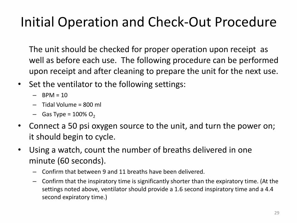
The unit should be checked for proper operation upon receipt as well as before each use. The following procedure can be performed upon receipt and after cleaning to prepare the unit for the next use.
• Set the ventilator to the following settings:– BPM = 10
– Tidal Volume = 800 ml
– Gas Type = 100% O2
• Connect a 50 psi oxygen source to the unit, and turn the power on; it should begin to cycle.
• Using a watch, count the number of breaths delivered in one minute (60 seconds).– Confirm that between 9 and 11 breaths have been delivered.
– Confirm that the inspiratory time is significantly shorter than the expiratory time. (At the settings noted above, ventilator should provide a 1.6 second inspiratory time and a 4.4 second expiratory time.)
29

Initial Operation and Check-Outcontinued
• Set the pressure relief to the 60 cm H2O mark and occlude the output fitting of the vent circuit output by placing your hand over the opening.– Confirm that the airway pressure on the LCD does not exceed 60 cm H2O.
– Confirm that there is an audible squeak from the pressure relief valve, signaling that the pressure relief has actuated.
– Note: The high airway pressure alarm may also sound during this portion of the test
• Press and release the manual breath button and confirm that
a breath is triggered.
• Set the low pressure alarm to 10 cm H2O and the high pressure alarm to 30 cm of H2O.
• With the ventilator output open, let the vent cycle for 20 seconds.– Confirm that the low airway pressure alarm sounds and the low airway pressure set
point is flashing on the LCD screen. 30

Initial Operation and Check-Outcontinued
• Occlude the ventilator output with your hand for 20 seconds– Confirm that the low pressure alarm has cleared.
– Confirm that the high airway pressure alarm sounds and the high airway pressure set point is flashing on the LCD screen.
• Set the high airway pressure alarm to 80 cm H2O and let the vent cycle for 10 seconds.– Confirm that the high pressure alarm has cleared.
• Turn the source gas off and wait for the pressure to drop.– Confirm that the low gas indicator is displayed on the LCD screen.
– Confirm that the low source gas alarm sounds
• Visually inspect the anti-suffocation valve in the ventilator outlet fitting to verify that it is laying flat against the inside of the fitting.
31
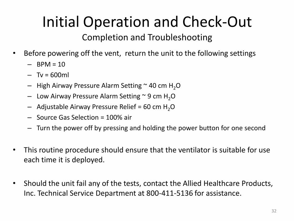
Initial Operation and Check-OutCompletion and Troubleshooting
• Before powering off the vent, return the unit to the following settings
– BPM = 10
– Tv = 600ml
– High Airway Pressure Alarm Setting ~ 40 cm H2O
– Low Airway Pressure Alarm Setting ~ 9 cm H2O
– Adjustable Airway Pressure Relief = 60 cm H2O
– Source Gas Selection = 100% air
– Turn the power off by pressing and holding the power button for one second
• This routine procedure should ensure that the ventilator is suitable for use each time it is deployed.
• Should the unit fail any of the tests, contact the Allied Healthcare Products, Inc. Technical Service Department at 800-411-5136 for assistance.
32

Routine Maintenance Cleaning and Disinfecting
• The MCV100(B) should be cleaned and disinfected after each use. – Wipe the unit down with a damp rag containing a mild cleaning solution to remove any
residue from the surface.
– Once the residue has been removed, the unit should be wiped with isopropyl alcohol or a cold disinfecting solution to kill bacteria.
– The unit should then be wiped down with water to remove any film left by the cold disinfecting solution.
– Make sure the unit is dry before putting the unit away.
• The following is a list of tested disinfecting solutions:
• Isopropyl Alcohol: 70% IPA• Alconox: I tablespoon Alconox to 1 gallon H2O• Cetylcide: 2 tablespoons Cetylcide to 1 gallon H2O• Bleach: 10% bleach in H2O
33

Routine Maintenance Particle Filter Replacement
• The MCV100(B) contains a particle filter located inside the air inlet on the side of the unit. This filter cleans the ambient air drawn in by the compressors and also cleans the air used in the function of the blender. This filter should be checked every 4 months and changed if visibly dirty. To replace the filter, remove the protective screen by prying off the cap with a fingernail or sharp object. Once the screen is removed, the foam filter can be removed and replaced.
34
Protective Screen(covers foam particle filter)
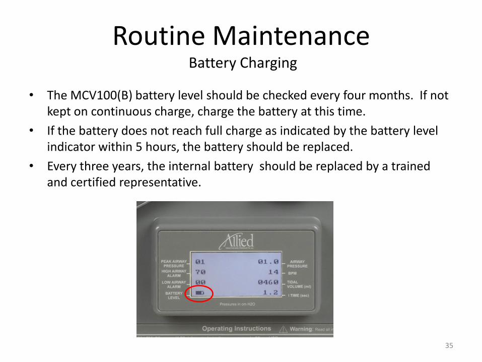
Routine Maintenance Battery Charging
• The MCV100(B) battery level should be checked every four months. If not kept on continuous charge, charge the battery at this time.
• If the battery does not reach full charge as indicated by the battery level indicator within 5 hours, the battery should be replaced.
• Every three years, the internal battery should be replaced by a trained and certified representative.
35

We hope this guide has prepared you to properly and safely use and maintain your MCV100 and MCV100-B portable ventilator.
If you have additional questions or require technical assistance, please contact our Technical Service Department.
800-411-5136
Technical Support Contact Information
36