operating system - pasc.edu.in · operating system r.padma, dept of cs page 6 1.7.4 context...
TRANSCRIPT

OPERATING SYSTEM
R.PADMA, DEPT OF CS Page 1
OPERATING SYSTEM
UNIT I
DEFINITION
• A program that acts as an intermediary between a user of a computer and the computer
hardware.
• Operating system goals:
Execute user programs and make solving user problems easier.
Make the computer system convenient to use.
• Use the computer hardware in an efficient manner.
1.1 INTRODUCTION
• Unprecedented growth of computing during the past several decades.
• Desktop workstations execute billions of instructions per second (BIPS)
• Supercomputers can execute over a trillion instructions per second
• Computers are now employed in almost every aspect of life.
1.2 WHAT IS AN OPERATING SYSTEM?
• Some years ago an operating system was defined as the software that controls the hardware.
• Landscape of computer systems has evolved significantly, requiring a more complicated
definition.
• Applications are now designed to execute concurrently.
1.3 OPERATING SYSTEM COMPONENTS AND GOALS
• Computer systems have evolved
– Early systems contained no operating system,
– Later gained multiprogramming and timesharing machines
– Personal computers and finally truly distributed systems
– Filled new roles as demand changed and grew

OPERATING SYSTEM
R.PADMA, DEPT OF CS Page 2
1.4 OPERATING SYSTEM GOALS
• Users expect certain properties of operating systems
– Efficiency – Robustness – Scalability
– Extensibility– Portability – Security
– Protection – Interactivity – Usability
Computer System Components
Hardware
Operating system
Applications programs
Users
PROCESS CONCEPTS
1.5 INTRODUCTION
• Computers perform operations concurrently
– For example, compiling a program, sending a file to a printer, rendering a Web page,
playing music and receiving e-mail
– Processes enable systems to perform and track simultaneous activities
– Processes transition between process states
– Operating systems perform operations on processes such as creating, destroying,
suspending, resuming and waking.
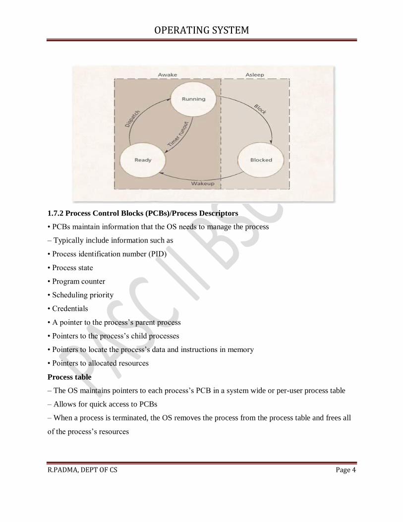
1.6 PROCESS STATES: LIFE CYCLE OF A PROCESS
• A process moves through a series of discrete process states:
– Running state
• The process is executing on a processor
– Ready state
• The process could execute on a processor if one were available
– Blocked state
• The process is waiting for some event to happen before it can proceed

OPERATING SYSTEM
R.PADMA, DEPT OF CS Page 3
• The OS maintains a ready list and a blocked list to store references to processes not running.
1.7 PROCESS MANAGEMENT
• Operating systems provide fundamental services to processes including:
– Creating processes – Destroying processes
– Suspending processes – Resuming processes
– Changing a process’s priority
– Blocking processes – Waking up processes
– Dispatching processes – Inter process communication (IPC)
1.7.1 Process States And State Transitions
• Process states
– The act of assigning a processor to the first process on the ready list is called dispatching
– The OS may use an interval timer to allow a process to run for a specific time interval or
quantum
– Cooperative multitasking lets each process run to completion
• State Transitions
– At this point, there are four possible state transitions
• When a process is dispatched, it transitions from ready to running
• When the quantum expires, it transitions from running to ready
• When a process blocks, it transitions from running to blocked
• When the event occurs, it transitions from blocked to ready Process state transitions
OPERATING SYSTEM
R.PADMA, DEPT OF CS Page 4
1.7.2 Process Control Blocks (PCBs)/Process Descriptors
• PCBs maintain information that the OS needs to manage the process
– Typically include information such as
• Process identification number (PID)
• Process state
• Program counter
• Scheduling priority
• Credentials
• A pointer to the process’s parent process
• Pointers to the process’s child processes
• Pointers to locate the process’s data and instructions in memory
• Pointers to allocated resources
Process table
– The OS maintains pointers to each process’s PCB in a system wide or per-user process table
– Allows for quick access to PCBs
– When a process is terminated, the OS removes the process from the process table and frees all
of the process’s resources

OPERATING SYSTEM
R.PADMA, DEPT OF CS Page 5
1.7.3 Process Operations
• A process may spawn a new process
– The creating process is called the parent process
– The created process is called the child process
– Exactly one parent process creates a child
– When a parent process is destroyed, operating systems typically respond in one of two ways:
• Destroy all child processes of that parent
• Allow child processes to proceed independently of their parents 3.3.4 Suspend and Resume
• Suspending a process
– Indefinitely removes it from contention for time on a processor without being destroyed
– Useful for detecting security threats and for software debugging purposes
– A suspension may be initiated by the process being suspended or by another process
– A suspended process must be resumed by another process
– Two suspended states:
• suspendedready
• suspendedblocked

OPERATING SYSTEM
R.PADMA, DEPT OF CS Page 6
1.7.4 Context Switching
• Context switches
– Performed by the OS to stop executing a running process and begin executing a previously
ready process
– Save the execution context of the running process to its PCB
– Load the ready process’s execution context from its PCB
– Must be transparent to processes
– Require the processor to not perform any “useful” computation
• OS must therefore minimize context-switching time

OPERATING SYSTEM
R.PADMA, DEPT OF CS Page 7
– Performed in hardware by some architectures
1.8 INTERRUPTS
• Interrupts enable software to respond to signals from hardware
– May be initiated by a running process
• Interrupt is called a trap
• Synchronous with the operation of the process
• For example, dividing by zero or referencing protected memory
– May be initiated by some event that may or may not be related to the running process
• Asynchronous with the operation of the process
• For example, a key is pressed on a keyboard or a mouse is moved
– Low overhead
• Polling is an alternative approach
– Processor repeatedly requests the status of each device
– Increases in overhead as the complexity of the system increases 3.4.1 Interrupt Processing
• Handling interrupts

OPERATING SYSTEM
R.PADMA, DEPT OF CS Page 8
– After receiving an interrupt, the processor completes execution of the current instruction, then
pauses the current process
– The processor will then execute one of the kernel’s interrupt handling functions
– The interrupt handler determines how the system should respond
– Interrupt handlers are stored in an array of pointers called the interrupt vector
– After the interrupt handler completes, the interrupted process is restored and executed or the
next process is executed
1.8.1 Interrupt Classes
• Supported interrupts depend on a system’s architecture
– The IA-32 specification distinguishes between two types of signals a processor may receive:
• Interrupts
– Notify the processor that an event has occurred or that an external device’s status has changed
– Generated by devices external to a processor
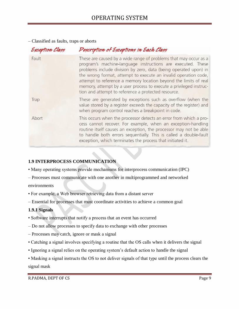
• Exceptions
– Indicate that an error has occurred, either in hardware or as a result of a software instruction
OPERATING SYSTEM
R.PADMA, DEPT OF CS Page 9
– Classified as faults, traps or aborts
1.9 INTERPROCESS COMMUNICATION
• Many operating systems provide mechanisms for interprocess communication (IPC)
– Processes must communicate with one another in multiprogrammed and networked
environments
• For example, a Web browser retrieving data from a distant server
– Essential for processes that must coordinate activities to achieve a common goal
1.9.1 Signals
• Software interrupts that notify a process that an event has occurred
– Do not allow processes to specify data to exchange with other processes
– Processes may catch, ignore or mask a signal
• Catching a signal involves specifying a routine that the OS calls when it delivers the signal
• Ignoring a signal relies on the operating system’s default action to handle the signal
• Masking a signal instructs the OS to not deliver signals of that type until the process clears the
signal mask

OPERATING SYSTEM
R.PADMA, DEPT OF CS Page 10
1.9.2 Message Passing
• Message-based interprocess communication
– Messages can be passed in one direction at a time
• One process is the sender and the other is the receiver
– Message passing can be bidirectional
• Each process can act as either a sender or a receiver
– Messages can be blocking or nonblocking
• Blocking requires the receiver to notify the sender when the message is received
• Nonblocking enables the sender to continue with other processing
– Popular implementation is a pipe
• A region of memory protected by the OS that serves as a buffer, allowing two or more
processes to exchange data
IPC in distributed systems
– Transmitted messages can be flawed or lost
• Acknowledgement protocols confirm that transmissions have been properly received
• Timeout mechanisms retransmit messages if acknowledgements are not received
– Ambiguously named processes lead to incorrect message referencing
• Messages are passed between computers using numbered ports on which processes listen,
avoiding this problem
– Security is a significant problem
• Ensuring authentication
UNIT II

OPERATING SYSTEM
R.PADMA, DEPT OF CS Page 11
ASYNCHRONOUS CONCURRENT EXECUTION
2.1 INTRODUCTION
• Concurrent execution
– More than one thread exists in system at once
– Can execute independently or in cooperation
– Asynchronous execution
• Threads generally independent
• Must occasionally communicate or synchronize
• Complex and difficult to manage such interactions
2.2 MUTUAL EXCLUSION
• Problem of two threads accessing data simultaneously
– Data can be put in inconsistent state
• Context switch can occur at anytime, such as before a thread finishes modifying value
– Such data must be accessed in mutually exclusive way
• Only one thread allowed access at one time
• Others must wait until resource is unlocked
• Serialized access
• Must be managed such that wait time not unreasonable.
2.2.1 Java Multithreading Case Study, Part II:
A Producer/Consumer Relationship in Java
• Producer/Consumer relationship
– One thread creates data to store in shared object
– Second thread reads data from that object
• Large potential for data corruption if unsynchronized

OPERATING SYSTEM
R.PADMA, DEPT OF CS Page 12
Buffer interface used in producer/consumer examples

OPERATING SYSTEM
R.PADMA, DEPT OF CS Page 13

OPERATING SYSTEM
R.PADMA, DEPT OF CS Page 14

OPERATING SYSTEM
R.PADMA, DEPT OF CS Page 15
SharedBuffer class enables threads to modify a shared object without synchronization.

OPERATING SYSTEM
R.PADMA, DEPT OF CS Page 16
2.2.2 Critical Sections
• Most code is safe to run concurrently
• Sections where shared data is modified must be protected
– Known as critical sections
– Only one thread can be in its critical section at once
• Must be careful to avoid infinite loops and blocking inside a critical Section
2.2.3 Mutual Exclusion Primitives
• Indicate when critical data is about to be accessed
– Mechanisms are normally provided by programming language or
libraries
– Delimit beginning and end of critical section
• enterMutualExclusion
• exitMutualExclusion
2.3 IMPLEMENTING MUTUAL EXCLUSION PRIMITIVES
• Common properties of mutual exclusion primitives
– Each mutual exclusion machine language instruction is executed indivisibly
– Cannot make assumptions about relative speed of thread execution
– Thread not in its critical section cannot block other threads from entering their critical
sections
– Thread may not be indefinitely postponed from entering its critical section
2.4 SOFTWARE SOLUTIONS TO THE MUTUAL EXCLUSION PROBLEM
2.4.1 Dekker’s Algorithm
• First version of Dekker’s algorithm
– Succeeds in enforcing mutual exclusion
– Uses variable to control which thread can execute
OPERATING SYSTEM
R.PADMA, DEPT OF CS Page 17
– Constantly tests whether critical section is available
• Busy waiting
• Wastes significant processor time
– Problem known as lockstep synchronization
• Each thread can execute only in strict alternation
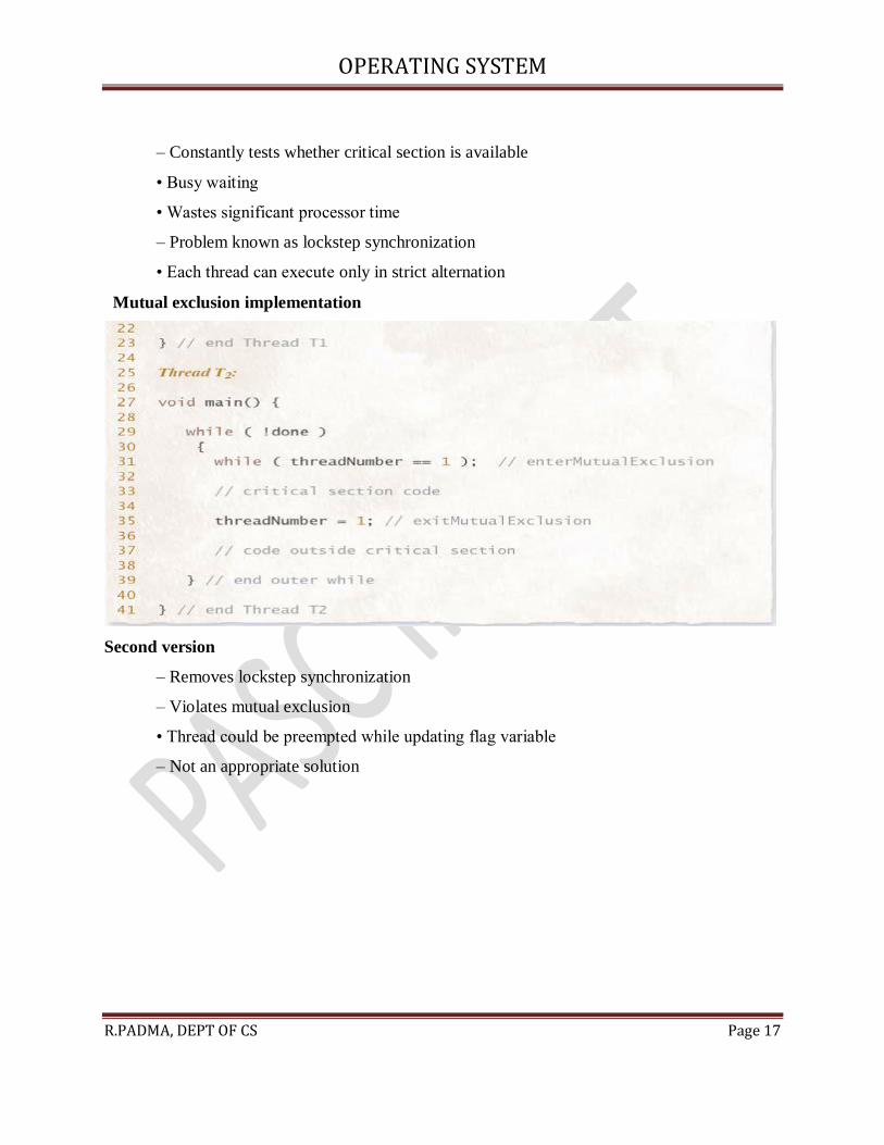
Mutual exclusion implementation
Second version
– Removes lockstep synchronization
– Violates mutual exclusion
• Thread could be preempted while updating flag variable
– Not an appropriate solution

OPERATING SYSTEM
R.PADMA, DEPT OF CS Page 18
Mutual exclusion implementation – version 2
Third version
– Set critical section flag before entering critical section test
• Once again guarantees mutual exclusion– Introduces possibility of deadlock
• Both threads could set flag simultaneously
• Neither would ever be able to break out of loop– Not a solution to the mutual exclusion
problem
Mutual exclusion implementation
OPERATING SYSTEM
R.PADMA, DEPT OF CS Page 19
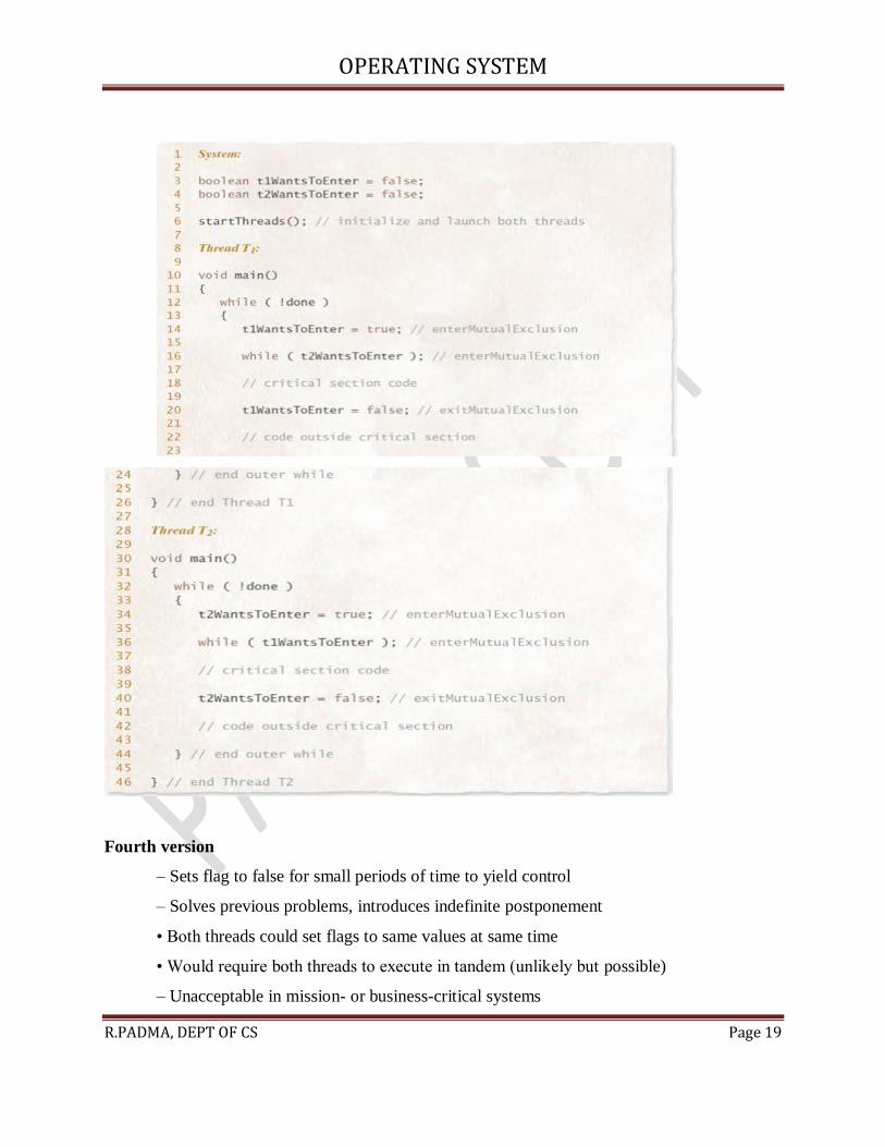
Fourth version
– Sets flag to false for small periods of time to yield control
– Solves previous problems, introduces indefinite postponement
• Both threads could set flags to same values at same time
• Would require both threads to execute in tandem (unlikely but possible)
– Unacceptable in mission- or business-critical systems

OPERATING SYSTEM
R.PADMA, DEPT OF CS Page 20
Mutual exclusion implementation

OPERATING SYSTEM
R.PADMA, DEPT OF CS Page 21
Dekker’s Algorithm – Final version
– Proper solution
– Uses notion of favored threads to determine entry into critical sections
• Resolves conflict over which thread should execute first
• Each thread temporarily unsets critical section request flag
• Favored status alternates between threads

OPERATING SYSTEM
R.PADMA, DEPT OF CS Page 22
– Guarantees mutual exclusion
– Avoids previous problems of deadlock, indefinite postponement
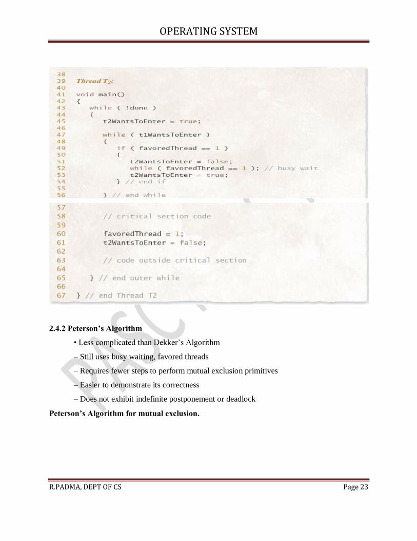
Dekker’s Algorithm for mutual exclusion
OPERATING SYSTEM
R.PADMA, DEPT OF CS Page 23
2.4.2 Peterson’s Algorithm
• Less complicated than Dekker’s Algorithm
– Still uses busy waiting, favored threads
– Requires fewer steps to perform mutual exclusion primitives
– Easier to demonstrate its correctness
– Does not exhibit indefinite postponement or deadlock
Peterson’s Algorithm for mutual exclusion.

OPERATING SYSTEM
R.PADMA, DEPT OF CS Page 24
OPERATING SYSTEM
R.PADMA, DEPT OF CS Page 25
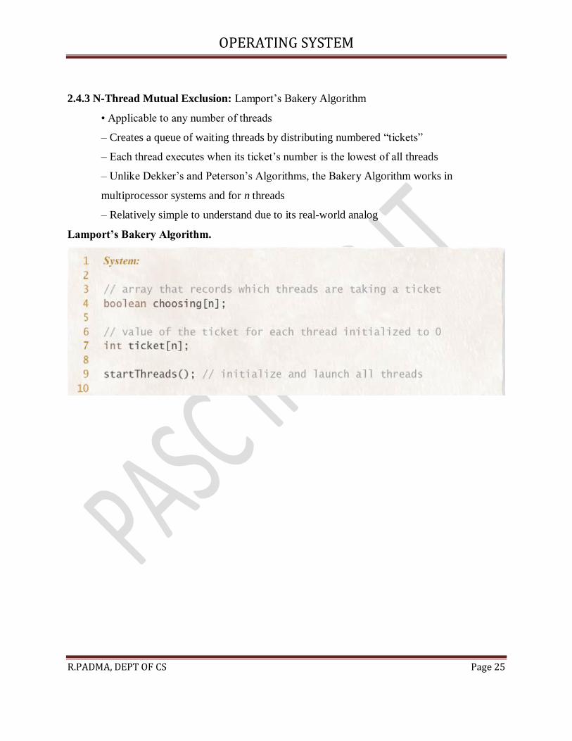
2.4.3 N-Thread Mutual Exclusion: Lamport’s Bakery Algorithm
• Applicable to any number of threads
– Creates a queue of waiting threads by distributing numbered “tickets”
– Each thread executes when its ticket’s number is the lowest of all threads
– Unlike Dekker’s and Peterson’s Algorithms, the Bakery Algorithm works in
multiprocessor systems and for n threads
– Relatively simple to understand due to its real-world analog
Lamport’s Bakery Algorithm.

OPERATING SYSTEM
R.PADMA, DEPT OF CS Page 26

OPERATING SYSTEM
R.PADMA, DEPT OF CS Page 27
2.5 HARDWARE SOLUTIONS TO THE MUTUAL EXCLUSION PROBLEM
• Implementing mutual exclusion in hardware
– Can improve performance – Can decreased development time
• No need to implement complex software mutual exclusion solutions like Lamport’s
Algorithm
2.2.1 Disabling Interrupts
• Disabling interrupts
– Works only on uniprocessor systems – Could result in deadlock
– Prevents the currently executing thread from being preempted
• For example, thread waiting for I/O event in critical section
– Technique is used rarely
2.2.2 Test-and-Set Instruction
OPERATING SYSTEM
R.PADMA, DEPT OF CS Page 28
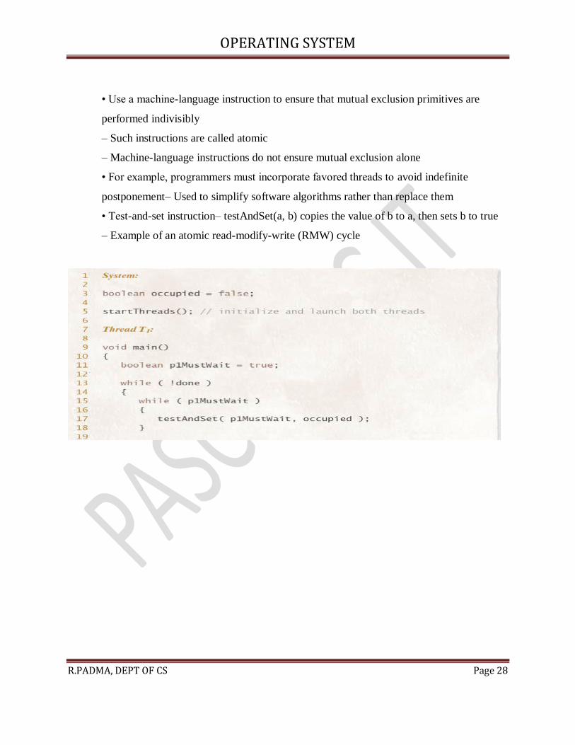
• Use a machine-language instruction to ensure that mutual exclusion primitives are
performed indivisibly
– Such instructions are called atomic
– Machine-language instructions do not ensure mutual exclusion alone
• For example, programmers must incorporate favored threads to avoid indefinite
postponement– Used to simplify software algorithms rather than replace them
• Test-and-set instruction– testAndSet(a, b) copies the value of b to a, then sets b to true
– Example of an atomic read-modify-write (RMW) cycle

OPERATING SYSTEM
R.PADMA, DEPT OF CS Page 29
2.2.3 Swap Instruction
• swap(a, b) exchanges the values of a and b atomically
• Similar in functionality to test-and-set
– swap is more commonly implemented on multiple architectures

OPERATING SYSTEM
R.PADMA, DEPT OF CS Page 30

OPERATING SYSTEM
R.PADMA, DEPT OF CS Page 31
2.6 SEMAPHORES
• Semaphores
– Software construct that can be used to enforce mutual exclusion
– Contains a protected variable
• Can be accessed only via wait and signal commands
• Also called P and V operations, respectively
2.6.1 Mutual Exclusion with Semaphores
• Binary semaphore: allow only one thread in its critical section at once
– Wait operation
• If no threads are waiting, allow thread into its critical section
• Decrement protected variable (to 0 in this case)
• Otherwise place in waiting queue – Signal operation
• Indicate that thread is outside its critical section
• Increment protected variable (from 0 to 1)
• A waiting thread (if there is one) may now enter
OPERATING SYSTEM
R.PADMA, DEPT OF CS Page 32
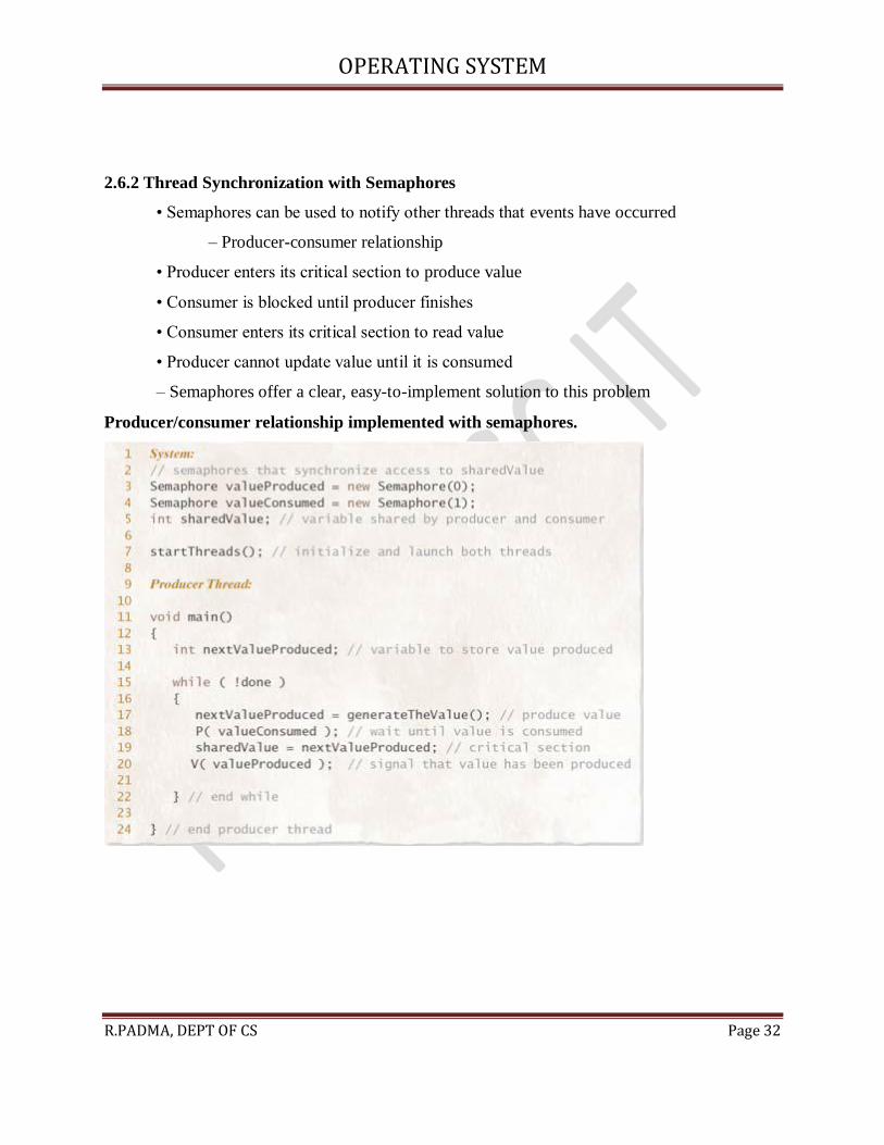
2.6.2 Thread Synchronization with Semaphores
• Semaphores can be used to notify other threads that events have occurred
– Producer-consumer relationship
• Producer enters its critical section to produce value
• Consumer is blocked until producer finishes
• Consumer enters its critical section to read value
• Producer cannot update value until it is consumed
– Semaphores offer a clear, easy-to-implement solution to this problem
Producer/consumer relationship implemented with semaphores.

OPERATING SYSTEM
R.PADMA, DEPT OF CS Page 33
2.6.3 Counting Semaphores
• Counting semaphores
– Initialized with values greater than one
– Can be used to control access to a pool of identical resources
• Decrement the semaphore’s counter when taking resource from pool
• Increment the semaphore’s counter when returning it to pool
• If no resources are available, thread is blocked until a resource becomes available
2.6.4 Implementing Semaphores
• Semaphores can be implemented at application or kernel level
– Application level: typically implemented by busy waiting
• Inefficient – Kernel implementations can avoid busy waiting
• Block waiting threads until they are ready
– Kernel implementations can disable interrupts

OPERATING SYSTEM
R.PADMA, DEPT OF CS Page 34
• Guarantee exclusive semaphore access
• Must be careful to avoid poor performance and deadlock
• Implementations for multiprocessor systems must use a more sophisticated approach
2.7 CONCURRENT PROGRAMMING - INTRODUCTION
• Recent interest in concurrent programming languages
– Naturally express solutions to inherently parallel problems
– Due to proliferation of multiprocessing systems, distributed systems and massively
parallel architectures
– More complex than standard programs
• More time required to write, test and debug
2.8 MONITORS
• Monitor– Contains data and procedures needed to allocate shared resources
• Accessible only within the monitor
• No way for threads outside monitor to access monitor data
• Resource allocation using monitors
– Thread must call monitor entry routine
– Mutual exclusion is rigidly enforced at monitor boundary
– A thread that tries to enter monitor when it is in use must wait
• Threads return resources through monitors as well
– Monitor entry routine calls signal
• Alerts one waiting thread to acquire resource and enter monitor
– Higher priority given to waiting threads than ones newly arrived
• Avoids indefinite postponement
2.8.1 Condition Variables
• Before a thread can reenter the monitor, the thread calling signal must first exit monitor
– Signal-and-exit monitor
• Requires thread to exit the monitor immediately upon signaling
• Signal-and-continue monitor

OPERATING SYSTEM
R.PADMA, DEPT OF CS Page 35
– Allows thread inside monitor to signal that the monitor will soon become available
– Still maintain lock on the monitor until thread exits monitor
– Thread can exit monitor by waiting on a condition variable or by completing execution
of code protected by monitor
2.8.2 Simple Resource Allocation with Monitors
• Thread inside monitor may need to wait outside until another thread performs an action
inside monitor
• Monitor associates separate condition variable with distinct situation that might cause
thread to wait– Every condition variable has an associated queue
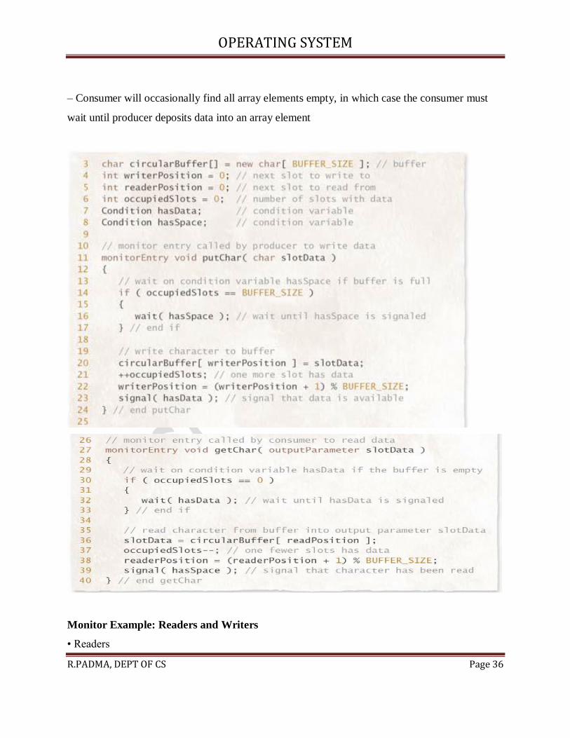
2.8.3 Monitor Example: Circular Buffer
• Circular buffer implementation of the solution to producer/consumer problem
– Producer deposits data in successive elements of array
– Consumer removes the elements in the order in which they were deposited (FIFO)
– Producer can be several items ahead of consumer
– If the producer fills last element of array, it must “wrap around” and begin depositing data in
the first element of array
• Due to the fixed size of a circular buffer
– Producer will occasionally find all array elements full, in which case the producer must wait
until consumer empties an array element
OPERATING SYSTEM
R.PADMA, DEPT OF CS Page 36
– Consumer will occasionally find all array elements empty, in which case the consumer must
wait until producer deposits data into an array element
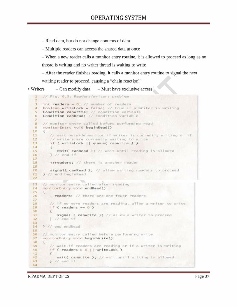
Monitor Example: Readers and Writers
• Readers
OPERATING SYSTEM
R.PADMA, DEPT OF CS Page 37
– Read data, but do not change contents of data
– Multiple readers can access the shared data at once
– When a new reader calls a monitor entry routine, it is allowed to proceed as long as no
thread is writing and no writer thread is waiting to write
– After the reader finishes reading, it calls a monitor entry routine to signal the next
waiting reader to proceed, causing a “chain reaction”
• Writers – Can modify data – Must have exclusive access

OPERATING SYSTEM
R.PADMA, DEPT OF CS Page 38
UNIT – 3
DEADLOCK AND INDEFINITE POSTPONEMENT
3.1 INTRODUCTION
• Deadlock
– A process or thread is waiting for a particular event that will not occur
• System deadlock
– One or more processes are deadlocked

OPERATING SYSTEM
R.PADMA, DEPT OF CS Page 39
3.2 EXAMPLES OF DEADLOCK
Deadlocks can develop in many ways. If a process is given the task of
waiting for an event to occur, and if the system includes no provision for
signaling that event, then have a one-process deadlock
3.2.1Traffic deadlock
3.2.2 Simple Resource Deadlock
• Most deadlocks develop because of the normal contention for dedicated resources
• Circular wait is characteristic of deadlocked systems
Resource deadlock example.

OPERATING SYSTEM
R.PADMA, DEPT OF CS Page 40
This
system is deadlocked because each process holds a resource being requested by the other process
and neither process is willing to release the resource it holds.
3.2.3 Deadlock in Spooling Systems
• Spooling systems are prone to deadlock
• Common solution
– Restrain input spoolers so that when the spooling file begins to reach some saturation
threshold, the spoolers do not read in more print jobs
• Today’s systems
– Printing begins before the job is completed so that a full spooling file can be emptied even
while a job is still executing
– Same concept has been applied to streaming audio and video
3.2.4 Example: Dining Philosophers
• Problem statement:

OPERATING SYSTEM
R.PADMA, DEPT OF CS Page 41
Five philosophers sit around a circular table. Each leads a simple life alternating between
thinking and eating spaghetti. In front of each philosopher is a dish of spaghetti that is constantly
replenished by a dedicated wait staff. There are exactly five forks on the table, one between each
adjacent pair of philosophers.Eating spaghetti (in the most proper manner) requires that a
philosopher use both adjacent forks (simultaneously). Develop a concurrent program free of
deadlock and indefinite postponement that models the activities of the philosophers.
Dining philosopher behavior
• Constraints:
– To prevent philosophers from starving:
• Free of deadlock
• Free of indefinite postponement
– Enforce mutual exclusion
• Two philosophers cannot use the same fork at once
• The problems of mutual exclusion, deadlock and indefinite postponement lie in the
implementation of method eat.

OPERATING SYSTEM
R.PADMA, DEPT OF CS Page 42
3.3 RELATED PROBLEM: INDEFINITE POSTPONEMENT
• Indefinite postponement
– Also called indefinite blocking or starvation
– Occurs due to biases in a system’s resource scheduling policies
• Aging
– Technique that prevents indefinite postponement by increasing process’s priority as it
waits for resource
3.4 RESOURCE CONCEPTS
• Preemptible resources (e.g. processors and main memory)
– Can be removed from a process without loss of work
• Nonpreemptible resources (e.g. tape drives and opticalscanners)
– Cannot be removed from the processes to which they are assigned without loss of work
• Reentrant code
– Cannot be changed while in use
– May be shared by several processes simultaneously
• Serially reusable code
– May be changed but is reinitialized each time it is used
– May be used by only one process at a time
3.5 FOUR NECESSARY CONDITIONS FOR DEADLOCK
• Mutual exclusion condition
– Resource may be acquired exclusively by only one process at a time
• Wait-for condition (hold-and-wait condition)
– Process that has acquired an exclusive resource may hold that resource while the
process waits to obtain other resources
• No-preemption condition
– Once a process has obtained a resource, the system cannot remove it from the process’s
control until the process has finished using the resource.
OPERATING SYSTEM
R.PADMA, DEPT OF CS Page 43
• Circular-wait condition
– Two or more processes are locked in a “circular chain” in which each process is waiting
for one or more resources that the next process in the chain is holding
3.6 DEADLOCK SOLUTIONS
• Four major areas of interest in deadlock research
– Deadlock prevention – Deadlock avoidance
– Deadlock detection – Deadlock recovery
3.7 DEADLOCK PREVENTION
• Deadlock prevention
– Condition a system to remove any possibility of deadlocks occurring
– Deadlock cannot occur if any one of the four necessary conditions is denied
– First condition (mutual exclusion) cannot be broken
3.7.1 Denying the “Wait-For” Condition
• When denying the “wait-for condition”
– All of the resources a process needs to complete its task must be requested at once
– This leads to inefficient resource allocation
3.7.2 Denying the “No-Preemption” Condition
• When denying the “no-preemption” condition
– Processes may lose work when resources are preempted
– This can lead to substantial overhead as processes must berestarted
3.7.3 Denying the “Circular-Wait” Condition
• Denying the “circular-wait” condition:
– Uses a linear ordering of resources to prevent deadlock
– More efficient resource utilization than the other strategies
• Drawbacks
– Not as flexible or dynamic as desired

OPERATING SYSTEM
R.PADMA, DEPT OF CS Page 44
– Requires the programmer to determine the ordering or resources for each system
Havender’s linear ordering of resources for preventing deadlock
3.8 Deadlock Avoidance with Dijkstra’s Banker’s Algorithm
• Banker’s Algorithm
– Impose less stringent conditions than in deadlock prevention in an attempt to get better
resource utilization
– Safe state
• Operating system can guarantee that all current processes can complete their work within a
finite time – Unsafe state
• Does not imply that the system is deadlocked, but that the OS cannot guarantee that all current
processes can complete their work within a finite time

OPERATING SYSTEM
R.PADMA, DEPT OF CS Page 45
– Requires that resources be allocated to processes only when the allocations result in
safe states.
– It has a number of weaknesses (such as requiring a fixed number of processes and
resources) that prevent it from being implemented in real systems
Safe state
.
Unsafe state
3.8.3 Example of Safe-State-to-Unsafe-State Transition
• Safe-state-to-unsafe-state transition:
– Suppose the current state of a system is safe, as shown in
– The current value of a is 2.
– Now suppose that process P3 requests an additional resource
Safe-state-to-unsafe-state transition.

OPERATING SYSTEM
R.PADMA, DEPT OF CS Page 46
3.8.4 Banker’s Algorithm Resource Allocation
• Is the state in the next slide safe?
State descriptions of three processes.
• Answer: – There is no guarantee that all of these processes will finish
• P2 will be able to finish by using up the two remaining resources
• Once P2 is done, there are only three available resources left
• This is not enough to satisfy either P1’s claim of 4 or P3’s claim of five
3.8.5 Weaknesses in the Banker’s Algorithm
• Weaknesses
– Requires there be a fixed number of resource to allocate
– Requires the population of processes to be fixed
– Requires the banker to grant all requests within “finite time”
– Requires that clients repay all loans within “finite time”
– Requires processes to state maximum needs in advance
3.9 Deadlock Detection
• Deadlock detection
– Used in systems in which deadlocks can occur
– Determines if deadlock has occurred
– Identifies those processes and resources involved in the deadlock
– Deadlock detection algorithms can incur significant runtime overhead
3.9.1 Resource-Allocation Graphs
• Resource-allocation graphs – Squares
• Represent processes – Large circles

OPERATING SYSTEM
R.PADMA, DEPT OF CS Page 47
• Represent classes of identical resources – Small circles drawn inside large circles
• Indicate separate identical resources of each class
Resource-allocation and request graphs.
3.9.2 Reduction of Resource-Allocation Graphs
• Graph reductions
– If a process’s resource requests may be granted, the graph may be reduced by that process
– If a graph can be reduced by all its processes, there is no deadlock
– If a graph cannot be reduced by all its processes, the irreducible processes constitute the set
of deadlocked processes in the graph
Graph reductions determining that no deadlock exists.

OPERATING SYSTEM
R.PADMA, DEPT OF CS Page 48
3.10 Deadlock Recovery
• Deadlock recovery
– Clears deadlocks from system so that deadlocked processes may complete their
execution and free their resources
• Suspend/resume mechanism
– Allows system to put a temporary hold on a process
– Suspended processes can be resumed without loss of work
• Checkpoint/rollback
– Facilitates suspend/resume capabilities
– Limits the loss of work to the time the last checkpoint was made
3.11 Deadlock Strategies in Current and Future Systems
• Deadlock is viewed as limited annoyance in personal computer systems
– Some systems implement basic prevention methods suggested by Havender

OPERATING SYSTEM
R.PADMA, DEPT OF CS Page 49
– Some others ignore the problem, because checking deadlocks would reduce systems’
performance
• Deadlock continues to be an important research area
PROCESSOR SCHEDULING
3.1 INTRODUCTION
• Processor scheduling policy
– Decides which process runs at given time
– Different schedulers will have different goals
• Maximize throughput
• Minimize latency
• Prevent indefinite postponement
• Complete process by given deadline
• Maximize processor utilization
3.2 SCHEDULING LEVELS
• High-level scheduling
– Determines which jobs can compete for resources
– Controls number of processes in system at one time
• Intermediate-level scheduling
– Determines which processes can compete for processors
– Responds to fluctuations in system load
• Low-level scheduling
– Assigns priorities – Assigns processors to processes
Scheduling Levels

OPERATING SYSTEM
R.PADMA, DEPT OF CS Page 50
3.3 PREEMPTIVE VS. NONPREEMPTIVE SCHEDULING
• Preemptive processes
– Can be removed from their current processor
– Can lead to improved response times
– Important for interactive environments
– Preempted processes remain in memory
• Nonpreemptive processes
– Run until completion or until they yield control of a processor
– Unimportant processes can block important ones indefinitely
3.4 PRIORITIES
• Static priorities
– Priority assigned to a process does not change

OPERATING SYSTEM
R.PADMA, DEPT OF CS Page 51
– Easy to implement – Low overhead
– Not responsive to changes in environment
• Dynamic priorities
– Responsive to change – Promote smooth interactivity
– Incur more overhead than static priorities
• Justified by increased responsiveness
3.5 SCHEDULING OBJECTIVES
• Different objectives depending on system
– Maximize throughput – Ensure predictability
– Maximize number of interactive processes receiving acceptable response times
– Minimize resource utilization – Avoid indefinite postponement
– Enforce priorities – Minimize overhead
• Several goals common to most schedulers
– Fairness – Predictability – Scalability
3.6 SCHEDULING CRITERIA
• Processor-bound processes – Use all available processor time
• I/O-bound – Generates an I/O request quickly and relinquishes processor
• Batch processes – Contains work to be performed with no user interaction
• Interactive processes – Requires frequent user input
3.7 SCHEDULING ALGORITHMS
• Scheduling algorithms
– Decide when and for how long each process runs – Make choices about
• Preemptibility • Priority • Running time • Fairness
• Run-time-to-completion
3.7.1 First-In-First-Out (FIFO) Scheduling
• FIFO scheduling

OPERATING SYSTEM
R.PADMA, DEPT OF CS Page 52
– Simplest scheme – Processes dispatched according to arrival time
– Nonpreemptible – Rarely used as primary scheduling algorithm
8.7.2 Round-Robin (RR) Scheduling
• Round-robin scheduling
– Based on FIFO– Preemptible
– Processes run only for a limited amount of time called a time slice or quantum
– Requires the system to maintain several processes in memory to minimize overhead
– Often used as part of more complex algorithms
• Selfish round-robin scheduling – Increases priority as process ages – Two queues
• Active • Holding– Favors older processes to avoids unreasonable delays
3.7.2 Round-Robin (RR) Scheduling
• Quantum size
– Determines response time to interactive requests – Very large quantum size
• Processes run for long periods
• Degenerates to FIFO – Very small quantum size
• System spends more time context switching than running processes– Middle-ground
• Long enough for interactive processes to issue I/O request

OPERATING SYSTEM
R.PADMA, DEPT OF CS Page 53
• Batch processes still get majority of processor time
3.7.3 Shortest-Process-First (SPF) Scheduling
• Scheduler selects process with smallest time to finish– Lower average wait time than FIFO
• Reduces the number of waiting processes
– Potentially large variance in wait times– Nonpreemptive
• Results in slow response times to arriving interactive requests
– Relies on estimates of time-to-completion
• Can be inaccurate or falsified– Unsuitable for use in modern interactive systems
3.7.4 Highest-Response-Ratio-Next (HRRN) Scheduling
• HRRN scheduling
– Improves upon SPF scheduling– Still nonpreemptive
– Considers how long process has been waiting– Prevents indefinite postponement
3.7.5 Shortest-Remaining-Time (SRT) Scheduling
• SRT scheduling
– Preemptive version of SPF
– Shorter arriving processes preempt a running process
– Very large variance of response times: long processes wait even longer than under SPF
– Not always optimal
• Short incoming process can preempt a running process that is near completion
• Context-switching overhead can become significant
3.7.6 Multilevel Feedback Queues
• Different processes have different needs
– Short I/O-bound interactive processes should generally run before processor-bound
batch processes– Behavior patterns not immediately obvious to the scheduler
• Multilevel feedback queues
– Arriving processes enter the highest-level queue and execute with higher priority than

OPERATING SYSTEM
R.PADMA, DEPT OF CS Page 54
processes in lower queues– Long processes repeatedly descend into lower levels
• Gives short processes and I/O-bound processes higher priority
• Long processes will run when short and I/O-bound processes terminate
– Processes in each queue are serviced using round-robin
• Process entering a higher-level queue preempts running processes
• Algorithm must respond to changes in environment
– Move processes to different queues as they alternate between interactive and batch
behavior
• Example of an adaptive mechanism– Adaptive mechanisms incur overhead that often is offset
by increased sensitivity to process behavior
Multilevel feedback queues
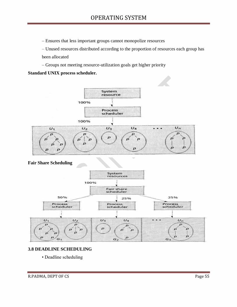
3.7.7 Fair Share Scheduling
• FSS controls users’ access to system resources
– Some user groups more important than others
OPERATING SYSTEM
R.PADMA, DEPT OF CS Page 55
– Ensures that less important groups cannot monopolize resources
– Unused resources distributed according to the proportion of resources each group has
been allocated
– Groups not meeting resource-utilization goals get higher priority
Standard UNIX process scheduler.
Fair Share Scheduling
3.8 DEADLINE SCHEDULING
• Deadline scheduling

OPERATING SYSTEM
R.PADMA, DEPT OF CS Page 56
– Process must complete by specific time – Used when results would be useless if not
delivered on-time – Difficult to implement
• Must plan resource requirements in advance
• Incurs significant overhead • Service provided to other processes can degrade
3.9 REAL-TIME SCHEDULING
• Real-time scheduling– Related to deadline scheduling
– Processes have timing constraints– Also encompasses tasks that execute periodically
• Two categories– Soft real-time scheduling
• Does not guarantee that timing constraints will be met
• For example, multimedia playback– Hard real-time scheduling
• Timing constraints will always be met
• Failure to meet deadline might have catastrophic results- For example, air traffic control
• Static real-time scheduling– Does not adjust priorities over time– Low overhead
– Suitable for systems where conditions rarely change
• Hard real-time schedulers– Rate-monotonic (RM) scheduling
• Process priority increases monotonically with the frequency with which it must execute
– Deadline RM scheduling
• Useful for a process that has a deadline that is not equal to its period.
• Dynamic real-time scheduling– Adjusts priorities in response to changing conditions
– Can incur significant overhead, but must ensure that the overhead does not result in
increased missed deadlines– Priorities are usually based on processes’ deadlines
• Earliest-deadline-first (EDF)
– Preemptive, always dispatch the process with the earliest deadline
• Minimum-laxity-first
– Similar to EDF, but bases priority on laxity, which is based on the process’s deadline
and its remaining run-time-to completion
UNIT – 4

OPERATING SYSTEM
R.PADMA, DEPT OF CS Page 57
REAL MEMORY ORGANIZATION AND MANAGEMENT
4.1 INTRODUCTION
• Memory divided into tiers– Main memory
• Relatively expensive • Relatively small capacity
• High-performance– Secondary storage • Cheap
• Large capacity • Slow– Main memory requires careful management
4.2 MEMORY ORGANIZATION
• Memory can be organized in different ways– One process uses entire memory space
– Each process gets its own partition in memory
• Dynamically or statically allocated
• Trend: Application memory requirements tend to increase over time to fill main memory
capacities
4.3 MEMORY MANAGEMENT
• Strategies for obtaining optimal memory performance – Performed by memory manager
• Which process will stay in memory?
• How much memory will each process have access to?
• Where in memory will each process go?

OPERATING SYSTEM
R.PADMA, DEPT OF CS Page 58
4.4 MEMORY HIERARCHY
• Main memory– Should store currently needed program instructions and data only
• Secondary storage– Stores data and programs that are not actively needed
• Cache memory
– Extremely high speed
– Usually located on processor itself
– Most-commonly-used data copied to cache for faster access
– Small amount of cache still effective for boosting performance
• Due to temporal locality
4.5 MEMORY MANAGEMENT STRATEGIES
• Strategies divided into several categories– Fetch strategies
• Demand or anticipatory
• Decides which piece of data to load next– Placement strategies
• Decides where in main memory to place incoming data– Replacement strategies

OPERATING SYSTEM
R.PADMA, DEPT OF CS Page 59
• Decides which data to remove from main memory to make more space
4.6 CONTIGUOUS VS. NONCONTIGUOUS MEMORY ALLOCATION
• Ways of organizing programs in memory – Contiguous allocation
• Program must exist as a single block of contiguous addresses
• Sometimes it is impossible to find a large enough blocks
• Low overhead – Noncontiguous allocation
• Program divided into chunks called segments
• Each segment can be placed in different part of memory
• Easier to find “holes” in which a segment will fit
• Increased number of processes that can exist simultaneously in memory offsets the overhead
incurred by this technique
4.7 FIXED-PARTITION MULTIPROGRAMMING
• I/O requests can tie up a processor for long periods – Multiprogramming is one solution
• Process not actively using a processor should relinquish it to others
• Requires several processes to be in memory at once
Processor utilization on a single-user system.
– Each active process receives a fixed-size block of memory
OPERATING SYSTEM
R.PADMA, DEPT OF CS Page 60
– Processor rapidly switches between each process
– Multiple boundary registers protect against damage
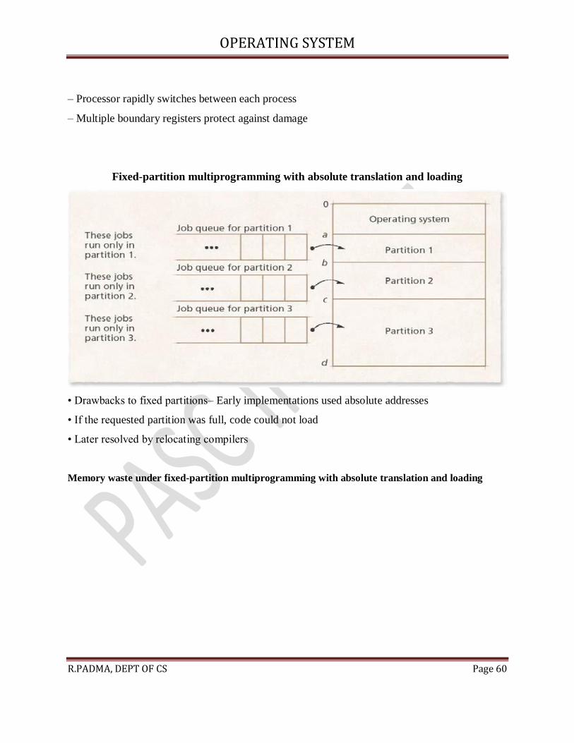
Fixed-partition multiprogramming with absolute translation and loading
• Drawbacks to fixed partitions– Early implementations used absolute addresses
• If the requested partition was full, code could not load
• Later resolved by relocating compilers
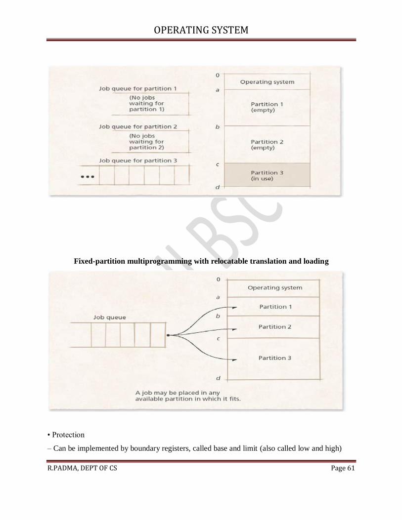
Memory waste under fixed-partition multiprogramming with absolute translation and loading
OPERATING SYSTEM
R.PADMA, DEPT OF CS Page 61
Fixed-partition multiprogramming with relocatable translation and loading
• Protection
– Can be implemented by boundary registers, called base and limit (also called low and high)

OPERATING SYSTEM
R.PADMA, DEPT OF CS Page 62
– Internal fragmentation
• Process does not take up entire partition, wasting memory
– Incurs more overhead
• Offset by higher resource utilization
4.8 VARIABLE-PARTITION MULTIPROGRAMMING
• System designers found fixed partitions too restrictive
– Internal fragmentation
– Potential for processes to be too big to fit anywhere
– Variable partitions designed as replacement
Initial partition assignments in variable-partition programming

OPERATING SYSTEM
R.PADMA, DEPT OF CS Page 63
4.8.1 Variable-Partition Characteristics
• Jobs placed where they fit– No space wasted initially– Internal fragmentation impossible
• Partitions are exactly the size they need to be – External fragmentation can occur when
processes removed
• Leave holes too small for new processes
• Eventually no holes large enough for new processes
Memory “holes” in variable-partition multiprogramming
•
Several ways to combat external fragmentation
– Coalescing
• Combine adjacent free blocks into one large block
• Often not enough to reclaim significant amount of memory
– Compaction
• Sometimes called garbage collection (not to be confused with GC in object-oriented languages)
• Rearranges memory into a single contiguous block free space and a single contiguous block of
occupied space
• Makes all free space available
• Significant overhead
Coalescing memory “holes” in variable-partition multiprogramming

OPERATING SYSTEM
R.PADMA, DEPT OF CS Page 64
Memory compaction in variable-partition multiprogramming

OPERATING SYSTEM
R.PADMA, DEPT OF CS Page 65
4.8.2 Memory Placement Strategies
• Where to put incoming processes – First-fit strategy
• Process placed in first hole of sufficient size found
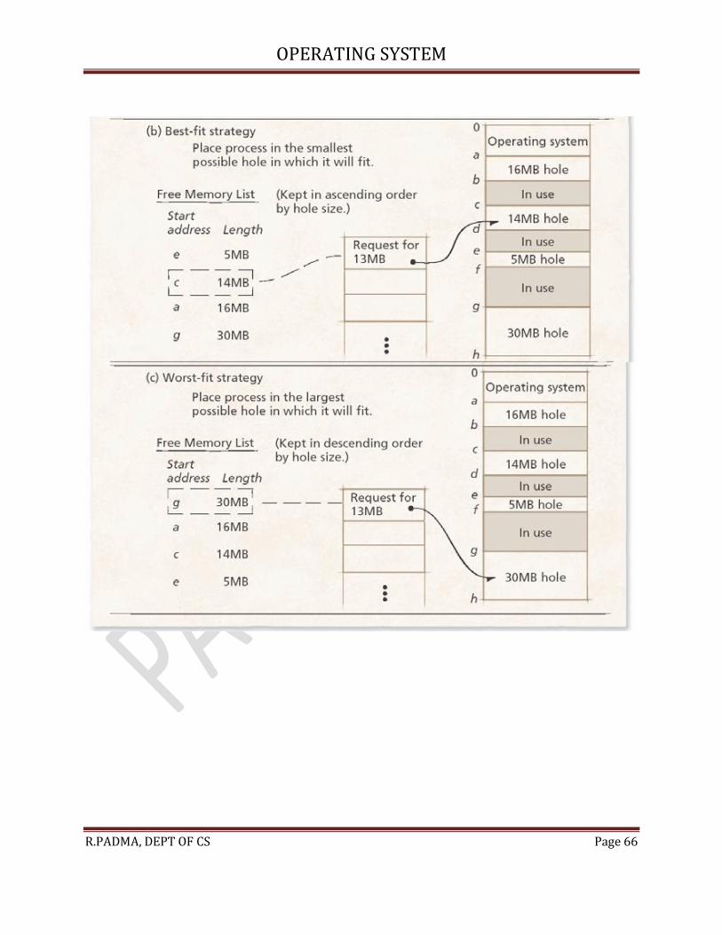
• Simple, low execution-time overhead – Best-fit strategy
• Process placed in hole that leaves least unused space around it
• More execution-time overhead – Worst-fit strategy
• Process placed in hole that leaves most unused space around it
• Leaves another large hole, making it more likely that another process can fit in the hole
First-fit, best-fit and worst-fit memory placement strategies
OPERATING SYSTEM
R.PADMA, DEPT OF CS Page 66

OPERATING SYSTEM
R.PADMA, DEPT OF CS Page 67
VIRTUAL MEMORY MANAGEMENT
4.9 INTRODUCTION
• Replacement strategy
– Technique a system employs to select pages for replacement when memory is full
– Determines where in main memory to place an incoming page or segment
• Fetch strategy
– Determines when pages or segments should be loaded into main memory
– Anticipatory fetch strategies
• Use heuristics to predict which pages a process will soon reference and load those pages or
segments
4.10 PAGE REPLACEMENT
• When a process generates a page fault, the memory manager must locate referenced page in
secondary storage, load it into page frame in main memory and update corresponding page table
entry
• Modified (dirty) bit
– Set to 1 if page has been modified; 0 otherwise
– Help systems quickly determine which pages have been modified
• Optimal page replacement strategy (OPT or MIN)
– Obtains optimal performance, replaces the page that will not be referenced again until furthest
into the future
4.11 PAGE-REPLACEMENT STRATEGIES
• A page-replacement strategy is characterized by
– Heuristic it uses to select a page for replacement
– The overhead it incurs
4.11.1 Random Page Replacement
• Random page replacement
OPERATING SYSTEM
R.PADMA, DEPT OF CS Page 68
– Low-overhead page-replacement strategy that does not discriminate against particular
processes
– Each page in main memory has an equal likelihood of being selected for replacement
– Could easily select as the next page to replace the page that will be referenced next
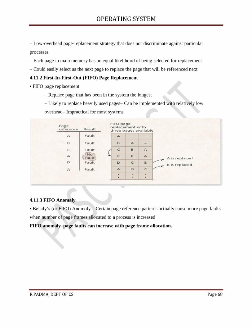
4.11.2 First-In-First-Out (FIFO) Page Replacement
• FIFO page replacement
– Replace page that has been in the system the longest
– Likely to replace heavily used pages– Can be implemented with relatively low
overhead– Impractical for most systems
4.11.3 FIFO Anomaly
• Belady’s (or FIFO) Anomoly – Certain page reference patterns actually cause more page faults
when number of page frames allocated to a process is increased
FIFO anomaly–page faults can increase with page frame allocation.

OPERATING SYSTEM
R.PADMA, DEPT OF CS Page 69
4.11.4 Least-Recently-Used (LRU) Page Replacement
• LRU page replacement
– Exploits temporal locality by replacing the page that has spent the longest time in memory
without being referenced
– Can provide better performance than FIFO
– Increased system overhead
– LRU can perform poorly if the least-recently used page is the next page to be referenced by a
program that is iterating inside a loop that references several pages.

OPERATING SYSTEM
R.PADMA, DEPT OF CS Page 70
4.11.5 Least-Frequently-Used (LFU) Page Replacement
• LFU page replacement
– Replaces page that is least intensively referenced
– Based on the heuristic that a page not referenced often is not likely to be referenced in
the future
– Could easily select wrong page for replacement
• A page that was referenced heavily in the past may never be referenced again, but will stay in
memory while newer, active pages are replaced
4.11.6 Not-Used-Recently (NUR) Page Replacement
• NUR page replacement
– Approximates LRU with little overhead by using referenced bit and modified bit to determine
which page has not been used recently and can be replaced quickly
– Can be implemented on machines that lack hardware referenced bit and/or modified bit
OPERATING SYSTEM
R.PADMA, DEPT OF CS Page 71
4.11.7 Modification to FIFO: Second-Chance and Clock
Page Replacement
• Second chance page replacement
– Examines referenced bit of the oldest page
• If it’s off
– The strategy selects that page for replacement
• If it’s on
– The strategy turns off the bit and moves the page to tail of
FIFO queue
– Ensures that active pages are the least likely to be replaced
• Clock page replacement
– Similar to second chance, but arranges the pages in circular list instead of linear list
4.11.8 Far Page Replacement
• Far page replacement
– Creates an access graph that characterizes a process’s reference patterns
– Replace the unreferenced page that is furthest away from any referenced page in the
access graph
– Performs at near-optimal levels
– Has not been implemented in real systems
• Access graph is complex to search and manage without hardware support
Far page-replacement-strategy access graph

OPERATING SYSTEM
R.PADMA, DEPT OF CS Page 72
4.12 Page-Fault-Frequency (PFF) Page Replacement
• Adjusts a process’s resident page set
– Based on frequency at which the process is faulting
– Based on time between page faults, called the process’s inter fault time
• Advantage of PFF over working set page replacement
– Lower overhead
• PFF adjusts resident page set only after each page fault
• Working set mechanism must operate after each memory reference
4.13 Page Release
• Inactive pages can remain in main memory for a long time until the management strategy
detects that the process no longer needs them
– One way to solve the problem
• Process issues a voluntary page release to free a page frame that it knows it no longer needs

OPERATING SYSTEM
R.PADMA, DEPT OF CS Page 73
• Eliminate the delay period caused by letting process gradually passthe page from its working
set
• The real hope is in compiler and operating system support
4.14 Page Size
• Some systems improve performance and memory utilization by providing multiple page sizes
– Small page sizes
• Reduce internal fragmentation
• Can reduce the amount of memory required to contain a process’s working set
• More memory available to other processes
– Large page size
• Reduce wasted memory from table fragmentation
• Enable each TLB entry to map larger region of memory, improving performance
• Reduce number of I/O operations the system performs to load a process’s working set into
memory
– Multiple page size
• Possibility of external fragmentation

OPERATING SYSTEM
R.PADMA, DEPT OF CS Page 74
UNIT - 5
DISK PERFORMANCE OPTIMIZATION
5.1 INTRODUCTION
• Secondary storage is one common bottleneck
– Improvements in secondary storage performance significantly boost overall system
performance
– Solutions can be both software- and hardware-based
5.2 WHY DISK SCHEDULING IS NECESSARY
• First-come-first-served (FCFS) scheduling has major drawbacks
– Seeking to randomly distributed locations results in long waiting times
– Under heavy loads, system can become overwhelmed
• Requests must be serviced in logical order to minimize delays
– Service requests with least mechanical motion

OPERATING SYSTEM
R.PADMA, DEPT OF CS Page 75
• The first disk scheduling algorithms concentrated on minimizing seek times, the component of
disk access that had the highest latency
• Modern systems perform rotational optimization as well
Components of a disk access
5.3 DISK SCHEDULING STRATEGIES
• Three criteria to measure strategies– Throughput
• Number of requests serviced per unit of time– Mean response time
• Average time spent waiting for request to be serviced– Variance of response times
• Measure of the predictability of response times
• Overall goals
– Maximize throughput
– Minimize response time and variance of response times
Disk request pattern

OPERATING SYSTEM
R.PADMA, DEPT OF CS Page 76
5.3.1 First-Come-First-Served (FCFS) Disk Scheduling
• FCFS scheduling: Requests serviced in order of arrival
– Advantages
• Fair • Prevents indefinite postponement • Low overhead
– Disadvantages
• Potential for extremely low throughput
– FCFS typically results in a random seek pattern because it does not reorder requests to reduce
service delays
OPERATING SYSTEM
R.PADMA, DEPT OF CS Page 77
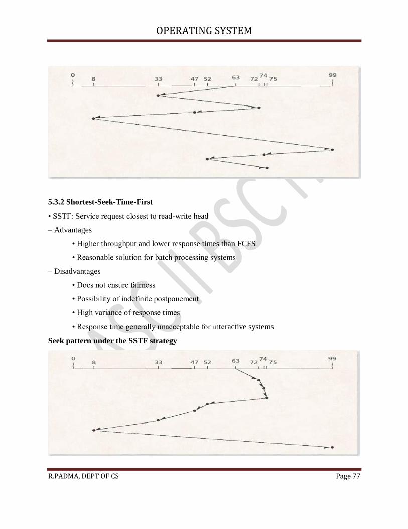
5.3.2 Shortest-Seek-Time-First
• SSTF: Service request closest to read-write head
– Advantages
• Higher throughput and lower response times than FCFS
• Reasonable solution for batch processing systems
– Disadvantages
• Does not ensure fairness
• Possibility of indefinite postponement
• High variance of response times
• Response time generally unacceptable for interactive systems
Seek pattern under the SSTF strategy

OPERATING SYSTEM
R.PADMA, DEPT OF CS Page 78
5.3.3 SCAN Disk Scheduling
• SCAN: Shortest seek time in preferred direction
– Does not change direction until edge of disk reached– Similar characteristics to SSTF
– Indefinite postponement still possible– Offers an improved variance of response times
Seek pattern under the SCAN strategy
5.3.4 C-SCAN Disk Scheduling
• C-SCAN: Similar to SCAN, but at the end of an inward sweep, the disk arm jumps (without
servicing requests) to the outermost cylinder
– Further reduces variance of response times as the expense of throughput and mean response
times
Seek pattern under the C-SCAN strategy

OPERATING SYSTEM
R.PADMA, DEPT OF CS Page 79
5.3.5 FSCAN and N-Step SCAN Disk Scheduling
• Groups requests into batches
• FSCAN: “freeze” the disk request queue periodically, service only those requests in the queue
at that time
• N-Step SCAN: Service only the first n requests in the queue at a time
– Both strategies prevent indefinite postponement
– Both reduce variance of response times compared to SCAN
Seek pattern under the FSCAN strategy
Seek pattern under the N-Step SCAN strategy (n = 3).

OPERATING SYSTEM
R.PADMA, DEPT OF CS Page 80
5.3.6 LOOK and C-LOOK Disk Scheduling
• LOOK: Improvement on SCAN scheduling
– Only performs sweeps large enough to service all requests
• Does move the disk arm to the outer edges of the disk if no requests for those regions are
pending
• Improves efficiency by avoiding unnecessary seek operations
• High throughput
• C-LOOK improves C-SCAN scheduling
– Combination of LOOK and C-SCAN
– Lower variance of response times than LOOK, at the expense of throughput
Seek pattern under the LOOK strategy

OPERATING SYSTEM
R.PADMA, DEPT OF CS Page 81
Seek optimization strategies summary

OPERATING SYSTEM
R.PADMA, DEPT OF CS Page 82
5.4 ROTATIONAL OPTIMIZATION
• Seek time formerly dominated performance concerns
– Today, seek times and rotational latency are the same order of magnitude
• Recently developed strategies attempt to optimization disk performance by reducing rotational
latency
• Important when accessing small pieces of data distributed throughout the disk surfaces
5.4.1 SLTF Scheduling
• Shortest-latency-time-first scheduling
– On a given cylinder, service request with shortest rotational latency first
– Easy to implement
– Achieves near-optimal performance for rotational latency
5.4.2 SPTF and SATF Scheduling
• Shortest-positioning-time-first scheduling
– Positioning time: Sum of seek time and rotational latency

OPERATING SYSTEM
R.PADMA, DEPT OF CS Page 83
– SPTF first services the request with the shortest positioning time
– Yields good performance
– Can indefinitely postpone requests
5.4.3 SPTF and SATF Scheduling
• Shortest-access-time-first scheduling
– Access time: positioning time plus transmission time
– High throughput
• Again, possible to indefinitely postpone requests
• Both SPTF and SATF can implement LOOK to improve performance
• Weakness
– Both SPTF and SATF require knowledge of disk performance characteristics which might not
be readily available due to error correcting data and transparent reassignment of bad sectors.
SPTF (a) and SATF (b) disk scheduling examples
OPERATING SYSTEM
R.PADMA, DEPT OF CS Page 84
FILE AND DATABASE SYSTEMS
5.5 Introduction
• Files
– Named collection of data that is manipulated as a unit
– Reside on secondary storage devices
• Operating systems can create an interface that facilitates navigation of a user’s files
– File systems can protect such data from corruption or total loss from disasters
– Systems that manage large amounts of shared data can benefit from databases as an alternative
to files
5.6 Data Hierarchy
• Information is stored in computers according to a data hierarchy.
• Lowest level of data hierarchy is composed of bits
– Bit patterns represent all data items of interest in computer systems
5.7 Data Hierarchy
• Next level in the data hierarchy is fixed-length patterns of bits such as bytes, characters and
words
– Byte: typically 8 bits
– Word: the number of bits a processor can operate on at once
– Characters map bytes (or groups of bytes) to symbols such as letters, numbers,
punctuation and new lines
• Three most popular character sets in use today: ASCII, EBCDIC and
Unicode
– Field: a group of characters
– Record: a group of fields
– File: a group of related records

OPERATING SYSTEM
R.PADMA, DEPT OF CS Page 85
• Highest level of the data hierarchy is a file system or database
• A volume is a unit of data storage that may hold multiple files
5.8 FILES
• File: a named collection of data that may be manipulated as a unit by operations such as:
– Open – Close – Create – List
– Destroy – Copy – Rename
• Individual data items within a file may be manipulated by operations like:
– Read – Write – Update
– Insert – Delete
• File characteristics include:
– Location – Accessibility – Type
– Volatility – Activity
• Files can consist of one or more records
5.9 FILE SYSTEMS
• File systems
– Organize files and manages access to data
– Responsible for file management, auxiliary storage management, file integrity mechanisms and
access methods
– Primarily are concerned with managing secondary storage space, particularly disk storage
5.10 FILE SYSTEMS
• File system characteristics – Should exhibit device independence.
• Users should be able to refer to their files by symbolic names rather than having to use physical
device names
– Should also provide backup and recovery capabilities to prevent either accidental loss or
malicious destruction of information

OPERATING SYSTEM
R.PADMA, DEPT OF CS Page 86
– May also provide encryption and decryption capabilities to make information useful only to its
intended audience
5.10.1 Directories
• Directories: – Files containing the names and locations of other files in the file system, to
organize and quickly locate files
• Directory entry stores information such as:
– File name – Location – Size – Type
– Accessed – Modified and creation times
Directory file contents example
• Single-level (or flat) file system:
– Simplest file system organization
– Stores all of its files using one directory
– No two files can have the same name
– File system must perform a linear search of the directory contents to locate each file, which can
lead to poor performance
• Hierarchical file system:
– A root indicates where on the storage device the root directory begins
– The root directory points to the various directories, each of which contains an entry for each of
its files

OPERATING SYSTEM
R.PADMA, DEPT OF CS Page 87
– File names need be unique only within a given user directory
– The name of a file is usually formed as the pathname from the root directory to the file
Two-level hierarchical file system
• Working directory
– Simplifies navigation using pathnames
– Enables users to specify a pathname that does not begin at the root directory (i.e., a relative
path)
– Absolute path (i.e., the path beginning at the root) = working directory + relative path
Example hierarchical file system contents

OPERATING SYSTEM
R.PADMA, DEPT OF CS Page 88
• Link: a directory entry that references a data file or directory located in a different directory
– Facilitates data sharing and can make it easier for users to access files located throughout a file
system’s directory structure
– Soft link: directory entry containing the pathname for another file
– Hard link: directory entry that specifies the location of the file (typically a block number) on
the storage device
– Because a hard link specifies a physical location of a file, it references invalid data when the
physical location of its corresponding file changes
– Because soft links store the logical location of the file in the file system, they do not require
updating when file data is moved
– However, if a user moves a file to different directory or renames the file, any soft links to that
file are no longer valid
Links in a file system

OPERATING SYSTEM
R.PADMA, DEPT OF CS Page 89
5.10.2 Metadata
• Metadata
– Information that protects the integrity of the file system
– Cannot be modified directly by users
• Many file systems create a superblock to store critical information that protects the integrity of
the file system – A superblock might contain:
• The file system identifier
• The location of the storage device’s free blocks
– To reduce the risk of data loss, most file systems distribute redundant copies of the superblock
throughout the storage device
• File open operation returns a file descriptor – A non-negative integer index into the open-file
table
• From this point on, access to the file is directed through the file descriptor
5.10.3 Mounting
• Mount operation
– Combines multiple file systems into one namespace so that they can be referenced from a
single root directory

OPERATING SYSTEM
R.PADMA, DEPT OF CS Page 90
• File systems manage mounted directories with mount tables:
– Contain information about the location of mount points and the devices to which they point
• When the native file system encounters a mount point, it uses the mount table to determine the
device and type of the mounted file system
• Users can create soft links to files in mounted file systems but cannot create hard links between
file systems
Mounting a file system
5.11 FILE ORGANIZATION
• File organization: the manner in which the records of a file are arranged on secondary storage
• File organization schemes include:
– Sequential – Direct – Indexed nonsequential – Partitioned
5.12 FILE ALLOCATION
• File allocation
– Problem of allocating and freeing space on secondary storage is somewhat like that
experienced in primary storage allocation under variable-partition multiprogramming
OPERATING SYSTEM
R.PADMA, DEPT OF CS Page 91
– Contiguous allocation systems have generally been replaced by more dynamic noncontiguous
allocation systems
• Files tend to grow or shrink over time
• Users rarely know in advance how large their files will be
5.12.1 Contiguous File Allocation
• Contiguous allocation
– Place file data at contiguous addresses on the storage device
– Advantages
• Successive logical records typically are physically adjacent to one another
– Disadvantages
• External fragmentation
• Poor performance can result if files grow and shrink over time
• If a file grows beyond the size originally specified and no contiguous free blocks are available,
it must be transferred to a new area of adequate size, leading to additional I/O operations.
5.12.2 Linked-List Noncontiguous File Allocation
• Sector-based linked-list noncontiguous file allocation scheme:
– A directory entry points to the first sector of a file
• The data portion of a sector stores the contents of the file
• The pointer portion points to the file’s next sector
– Sectors belonging to a common file form a linked list
5.12.3 Linked-List Noncontiguous File Allocation
• When performing block allocation, the system allocates blocks of contiguous sectors
(sometimes called extents)
• Block chaining
– Entries in the user directory point to the first block of each file
– File blocks contain:
• A data block
• A pointer to the next block

OPERATING SYSTEM
R.PADMA, DEPT OF CS Page 92
Noncontiguous file allocations using a linked list
5.12.4 Linked-List Noncontiguous File Allocation
• When locating a record
– The chain must be searched from the beginning
– If the blocks are dispersed throughout the storage device (which is normal), the search process
can be slow as block-to-block seeks occur
• Insertion and deletion are done by modifying the pointer in the previous block.
5.12.5 Linked-List Noncontiguous File Allocation
• Large block sizes – Can result in significant internal fragmentation
• Small block sizes – May cause file data to be spread across multiple blocks dispersed
throughout the storage device
– Poor performance as the storage device performs many seeks to access all the records of a file.
5.12.6 Tabular Noncontiguous File Allocation

OPERATING SYSTEM
R.PADMA, DEPT OF CS Page 93
• Tabular noncontiguous file allocation – Uses tables storing pointers to file blocks
• Reduces the number of lengthy seeks required to access a particular record
– Directory entries indicate the first block of a file
– Current block number is used as an index into the block allocation table to determine the
location of the next block.
• If the current block is the file’s last block, then its block allocation table entry is null
Tabular noncontiguous file allocation
5.12.7 Tabular Noncontiguous File Allocation
• Pointers that locate file data are stored in a central location
– The table can be cached so that the chain of blocks that compose a file can be traversed quickly
– Improves access times

OPERATING SYSTEM
R.PADMA, DEPT OF CS Page 94
• To locate the last record of a file, however:
– The file system might need to follow many pointers in the block allocation table
– Could take significant time
5.12.8 Tabular Noncontiguous File Allocation
• When a storage device contains many blocks:
– The block allocation table can become large and fragmented
– Reduces file system performance
• A popular implementation of tabular noncontiguous file allocation is Microsoft’s FAT file
system
5.12.9 Indexed Noncontiguous File Allocation
• Indexed noncontiguous file allocation:
– Each file has an index block or several index blocks
– Index blocks contain a list of pointers that point to file data blocks
– A file’s directory entry points to its index block, which may reserve the last few entries to store
pointers to more index blocks, a technique called chaining
• Primary advantage of index block chaining over simple linked-list implementations:
– Searching may take place in the index blocks themselves.
– File systems typically place index blocks near the data blocks they reference, so the data blocks
can be accessed quickly after their index block is loaded
Figure 13.8 Index block chaining.

OPERATING SYSTEM
R.PADMA, DEPT OF CS Page 95
• Index blocks are called inodes (i.e., index nodes) in UNIX-based operating systems
Inode structure

OPERATING SYSTEM
R.PADMA, DEPT OF CS Page 96
5.13 FREE SPACE MANAGEMENT
• Some systems use a free list to manage the storage device’s free space
– Free list: Linked list of blocks containing the locations of free blocks
– Blocks are allocated from the beginning of the free list
– Newly freed blocks are appended to the end of the list
• Low overhead to perform free list maintenance operations
• Files are likely to be allocated in noncontiguous blocks
– Increases file access time
Free space management using a free list
5.14 FREE SPACE MANAGEMENT
• A bitmap contains one bit for each block in memory
– ith bit corresponds to the ith block on the storage device
• Advantage of bitmaps over free lists:
– The file system can quickly determine if contiguous blocks are available at certain locations on
secondary storage
• Disadvantage of bitmaps:

OPERATING SYSTEM
R.PADMA, DEPT OF CS Page 97
– The file system may need to search the entire bitmap to find a free block, resulting in
substantial execution overhead
Free space management using a bitmap
5.15 FILE ACCESS CONTROL
• Files are often used to store sensitive data such as:
– Credit card numbers
– Passwords
– Social security numbers
• Therefore, they should include mechanisms to control user access to data.
– Access control matrix
– Access control by user classes
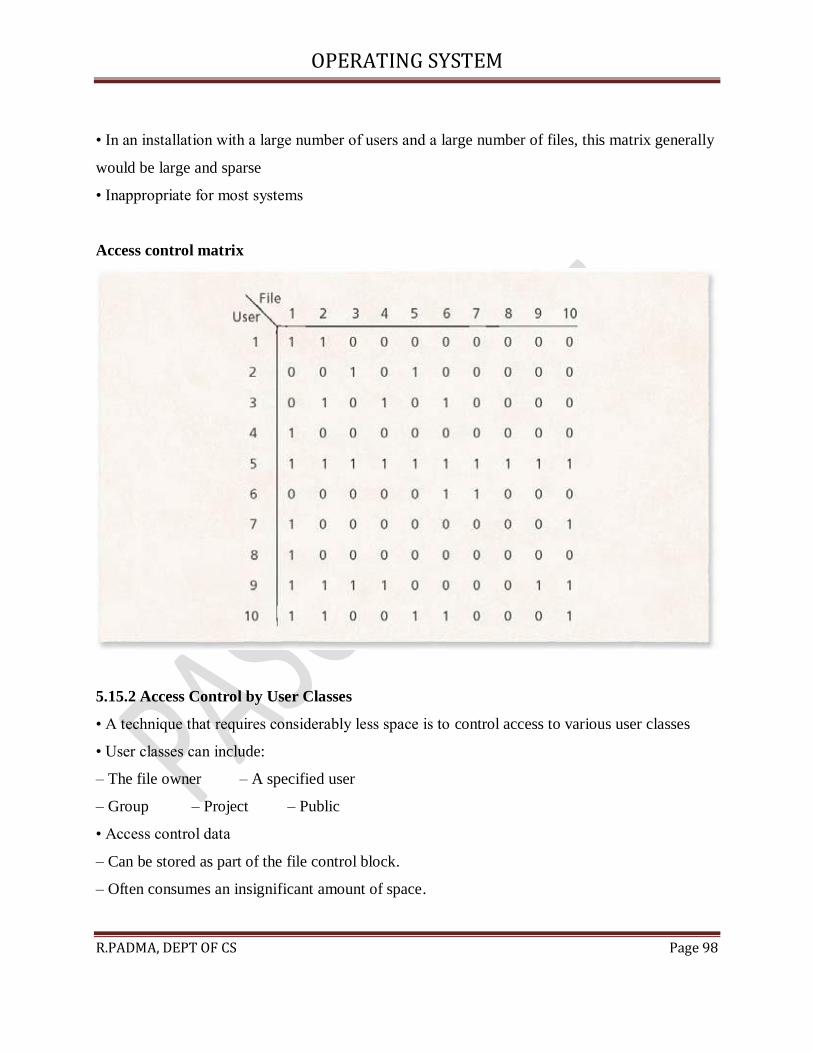
5.15.1 Access Control Matrix
• Two-dimensional access control matrix:
– Entry aij is 1 if user i is allowed access to file j – Otherwise aij = 0
OPERATING SYSTEM
R.PADMA, DEPT OF CS Page 98
• In an installation with a large number of users and a large number of files, this matrix generally
would be large and sparse
• Inappropriate for most systems
Access control matrix
5.15.2 Access Control by User Classes
• A technique that requires considerably less space is to control access to various user classes
• User classes can include:
– The file owner – A specified user
– Group – Project – Public
• Access control data
– Can be stored as part of the file control block.
– Often consumes an insignificant amount of space.