operating marco - hansen wholesale · location corners shoutd be considered where space is limited...
TRANSCRIPT

INSTALLING & OPERATING YOUR MARCO WOOD-BURNING
FIREPLACE
CHECK LOCAL CODES PRIOR TO INSTALLATION
ARCHITECT'S 41 " MASONRY FIREPLACES Patents Pending
OPTIONAL FEATURES: GLASS DOORS OUTSIDE AIR KIT
#
792870
792871
792872
THlS MANUAL PROVIDES ALL THE INSTRUCTIONS NECESSARY FOR THE BUILDER OR HOMEOWNER TO INSTALL THE ARCHITECTS 41" MASONRY FIREPLACES SAFELY AND EFFICIENTLY. IT ALSO PROVIDES INFORMATION ON HOW TO ORDER REPAIR PARTS WHEN NEEDED.
THIS SYMBOL ON THE PROOUCT MEANS IT iS LlSTED B Y
UNDERWRITERS UBOFIATORIES. INC.
MODEL REFERENCE
A41 MTR
A41 MTU
A41 MC
Ah,,. MARCO MFG., INC., 2520 Industry Way Lynwood, CA 90262 (213)564-3201
DESCRIPTION
ARCHITECT'S 41" MASONRY "TRADITIONAL"
ARCHITECT'S 41" MASONRY "TUDOR"
ARCHITECT'S 41" MASONRY "CUSTOM"


TABLE OF CONTENTS
I . ACCESSORIES . . . . . . . . . . . . . . . . . . . . . . . . . . . . . . . . . . . . . . . . . . . . . . . . . Page 1
11 . INSTALLATION INSTRUCTIONS Introduction . . . . . . . . . . . . . . . . . . . . . . . . . . . . . . . . . . . . . . . . . . . . . . . . . . . . . . . . Selecting Your Fireplace Location . . . . . . . . . . . . . . . . . . . . . . . . . . . . . . . . . . . . . Clearances . . . . . . . . . . . . . . . . . . . . . . . . . . . . . . . . . . . . . . . . . . . . . . . . . . . . . . . . .
. . . . . . . . . . . . . . . . . . . . . . . . . . . . . . . . . . . . . . . . . Fireplace Overall Dimensions . . . . . . . . . ..................................... Framing Instructions ..
Installation of Air Inlet Assemble ...................................... Examples of Fireplace & Chimney Designs ............................. Sample of MuItipfe Chase Installation ..................................
.............................. How to Determine Your Fireplace System Chimney Offsets Using Elbows ... . . . . . . . . . . . . . . . . . . . . . . . . . . . . . . . . . . . . Installing Your Double Wall Chimney ..................................
.................................................. Firestop Spacers Chimney Pipe Support ............................................... Storm Collar . ...................................................... Terminations . . . . . . . . . . . . . . . . . . . . . . . . . . . . . . . . . . . . . . . . . . . . . . . . . . . . . . . Installing the Gas Line . . . . . . . . . . . . . . . . . . . . . . . . . . . . . . . . . . . . . . . . . . . . . . . Gas Log tighter Installation .......................................... Optional Cold Climate Installation .....................................
Page 1 Page
I l t . FINISHING YOUR FIREPLACE Fireplace Facing ....................... .. .... . . . . . . . . . . . . . . . . . . . . . . Page 14 Hearth Extension . . . . . . . . . . . . . . . . . . . . . . . . . . . . . . . . . . . . . . . . . . . . . . . . . . . Page 15 Mantle "Surrounds" . . . . . . . . . . . . . . . . . . . . . . . . . . . . . . . . . . . . . . . . . . . . . . . . . Page 16
IV . OPERATION INSTRUCTIONS Damper Control .................................................... Page 17
............................................................ Grate Page 17 Outside Air Control . . . . . . . . . . . . . . . . . . . . . . . . . . . . . . . . . . . . . . . . . . . . . . . . Page 17 Do's and Don'ts ............... ; . . . . . . . . . . . . . . . . . . . . . . . . . . . . . . . . . . . . Page 18 Reference Documents ....................... .. ..... . . . . . . . . . . . . . . . . Page 18 Replacement Parts ................................................ Page 19
SAVE THIS BOOK This book is valuable . In addition to telling you how to install and maintain your fireplace and chimney. it also contains the inforrna- tion that will enable you to obtain repair parts when needed . Keep it with your other important papers .
KEEP YOUR FIREPLACE SAFE NEVER USE GASOLINE. GASOLINE-TYPE LANTERN FUEL. CHARCOAL LIGHTER FLUID OR SIMILAR LIQUIDS TO START OR *FRESHEN-UP" A FIRE IN THE FIREPLACE . KEEP ALL SUCH LIQUIDS WELL AWAY FROM THE FIREPLACE .
1. ACCESSORIES
FIREPLACE GRATE:
This unit has been equipped with a grate designed lo keep the operation of your fireplace efficienl and safe. See Page 17 for operating instructions.
GLASS DOORS:
Bi-fold glass doors can be installed as an optional accessory. Use MARCO door kit #793420 or #793421 and refer to the installation instmctions in that kit for installation details. The glass doors can be installed before, during or after the installation of the fireplace.
THE GLASS DOOR MOUNTS OVER THE FACING MATERIAL. TO ENSURE PROPER OPERATION, FACING MUST NOT PROTRUDE INTO THE FIRE- PLACE OPENING.
NOTE: Use of glass doors other than those manufactured by Marco Mfg., Inc. could create a potentially hazardous condition and will void the MARCO warranty.
OUTSIDE AIR:
An optional outside air kil is available for installation. An outside air kit must be installed during the instal- lation of the fireplace (See pages 4 & 5 ) .
The outside air damper mechanism is an integral part of the unit.
To complete the outside air kit you must purchase air inlet eyebrow #793255 and 4' diameter Class 0 or Class 1 flex duct (purchased locally).
11. INSTALLATION INSTRUCTIONS
INTRODUCTION:
This MARCO fireplace and components are safe when installed according to this Installation Manual. Unless you use MARCO components which have been designed and tested for the fireplace system, you may cause a fire hazard.
MARCO 41" Masonry fireplaces may be installed in a conventional home or a prefabricated home.
The MARCO warranty will be voided by, and MARCO disclaims any responsibility for, the following ac- tions:
a) Modification of the fireplace andlor components, including assembly of chimney, glass doors, air inlet system and damper control.
b) Use of any component part not manufactured or approved by MARCO in combination with a MARCO fireplace system.
c) Installalion other than as inslrucled in this rnan- ual.
DO NOT USE A FIREPLACE INSERT OR OTHER PRODUCTS NOT SPECIFIED FOR USE WITH THESE FIREPLACES.
- PROPER INSTALLATION is the most important step in ensuring safe, long-term operation of this fire- place. Consult the local building codes as to the particular requirements concerning installation of all factory-bui It fireplaces.
SELECTING YOUR FIREPLACE LOCATION
To determine the safest and most efficient location for your fireplace, consider such factors as room traffic, Iocation of doors and windows, and construction above and below the installation area. The fireplace may be installed in any location that is free of air conditioning ducts, electrical wiring, and plumbing. This location must also provide the necessary clearances,
+ Before beginning the installation of your fireplace, read through these instructions and the instructions contained in the separate Operation Manual.
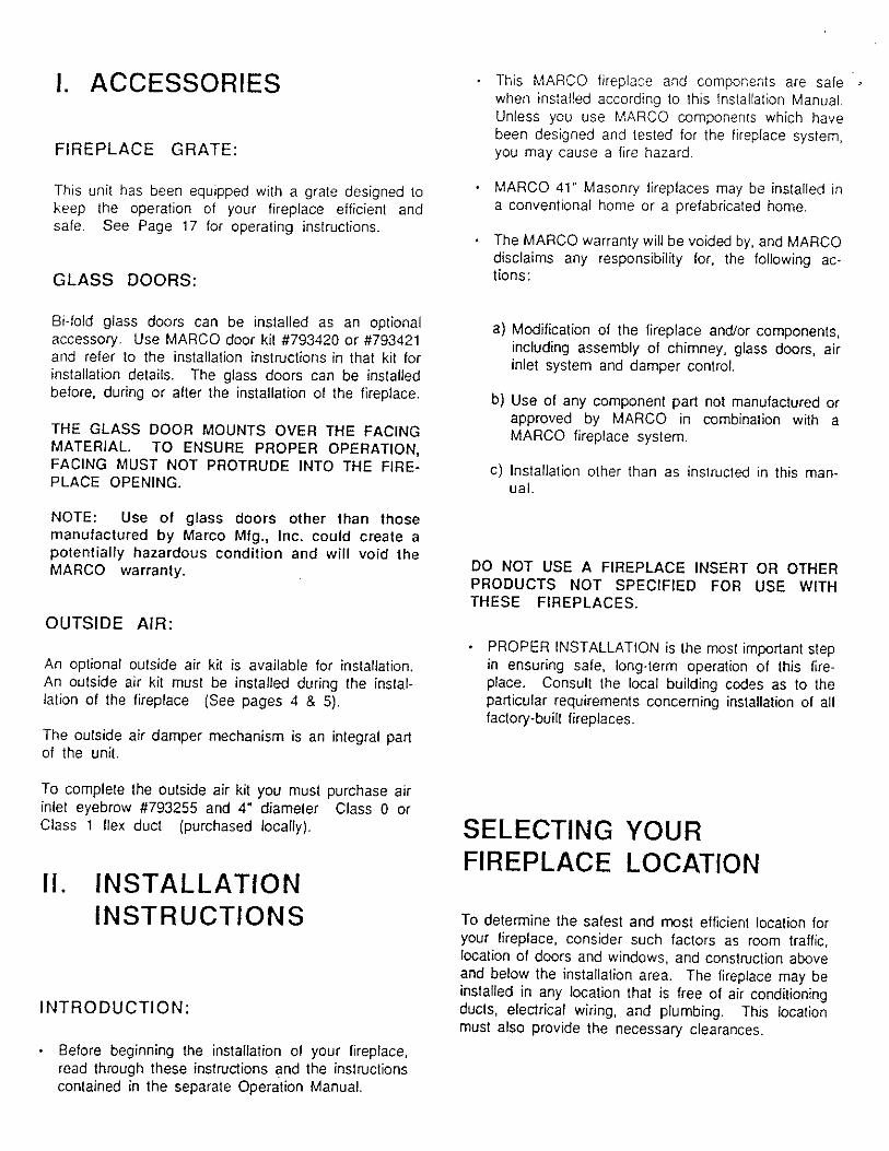
LOCATION
Corners shoutd be considered where space is limited or at a premium. A corner-installed fireplace can make use of space that may not normally be used (see Figure 1).
PROJECTION
FIGURE 1 LOCATlON AND INSTALLATION
. A fireplace may be installed flush with the linished wall or projecting any distance into the room. Flush installation is recommended for srnoolh or thin wall- facing materials. By installing the fireplace to project into the room, a shallower cavity is required fo contain the fireplace; thicker natural materials, such as field stone, can then be used for face material.
A location that requires cutting the least number of joists, roof rafters, and floor joists will reduce costs and make installation easier. This may mean moving only one or two inches from the selected ideal loca- tion. Any location selected must allow adequate room to accommodate the fireplace and framing dirnen- sions shown in Figures 4, 5 & 6.
SEE FIGURE 1 FOR LOCATION EXAMPLES. WHAT- EVER LOCATION IS CHOSEN, ACCESSIBILITY TO OUTSIDE COMBUSTION AIR SHOULD BE CONSID- ERED. (SEE PAGE 5).
Do not place the fireplace on soft-surfaced floor cov- ering such as carpeting. The mounting surface must be flat and hard (such as plywood, wood flooring, particle board or any other hard-surfaced material), and evenly support the total base of the fireplace. A raised platform may be used to support the fireplaces.
When a fireplace is installed on a combustible floor, a non-combustible hearth extension must be provided to protect the floor in front of the opening. (Refer to Hearth Extension, Pages 15 & 16).
CLEARANCES
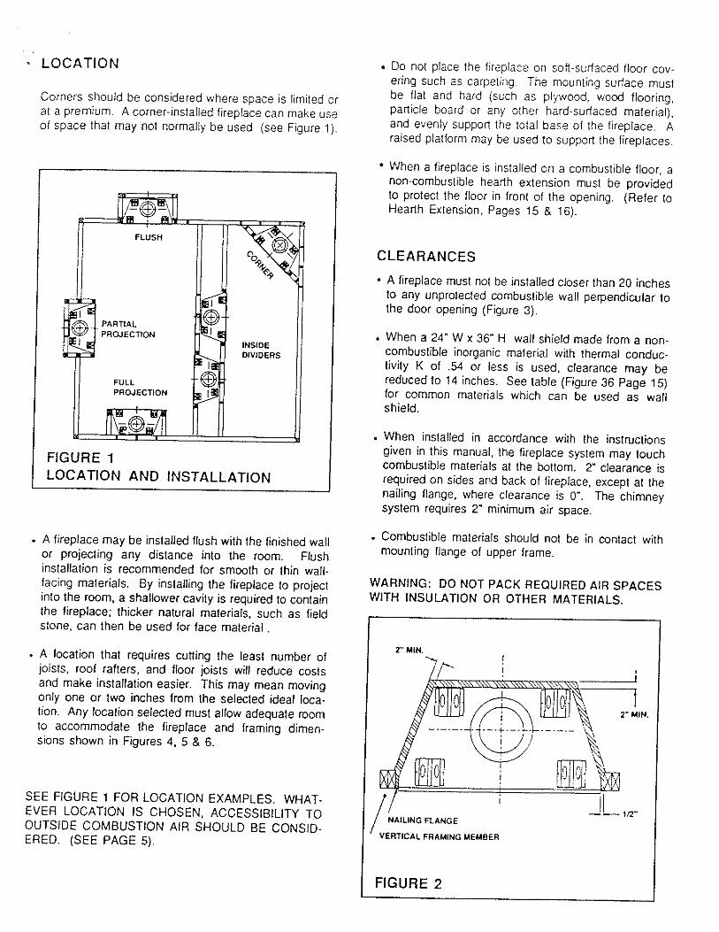
A fireplace must not be installed closer than 20 inches to any unprotected combustible wall perpendicular to the door opening (Figure 3).
. When a 24" W x 36" H wall shield made from a non- combustible inorganic materia! with thermal conduc- tivity K of .54 or less is used, clearance may be reduced to 14 inches. See table (Figure 36 Page 15) for common materials which can be used as wall shield.
. When installed in accordance with the instructions given in this manual, the fireplace system may touch combustible materials at the bottom. 2" clearance is required on sides arid back of fireplace, except at the nailing flange, where clearance is 0". The chimney system requires 2" minimum air space.
. Combustible materials should not be in contact with mounting flange of upper frame.
WARNING: DO NOT PACK REQUIRED AIR SPACES WITH INSULATION OR OTHER MATERIALS.
1 2" MIN.
NAlLlNG R A N G E
FIGURE 2

FRAMING INSTRUCTIONS
C
If framing around the fireplace is designed to incorpo- rate book shelves, wood bins, closets, etc.. these should not project beyond the safety zone (Figure 3).
BLACK PORTION OF FRAME NOT TO BE COVE RED WITH COMBUSTIBLE MATERIALS
FIGURE 3
/ 2" MIN.
U*
NOTE: SEE RGURE 5 FOR fRONT VIEW OF FRAMING.
FIGURE 4 - FRAMING DIMENSIONS

INSTALLING YOUR FIREPLACE METAL SAFETY STRIP-OFFSET (SUPPLIED BY OTHERS)
STEP 1 : Frame the cavity of opening for the fireplace at the chosen location (Figure 6). Move the fireplace
When the fireplace and hearth extension are not in- into position and install false header and metal safety
stalled at the same height a custom safety strip will strips (provided) under the fireplace as shown in
be required. The safely strip shall be constructed of Figure 7. a minimum thickness of .Dl8 galvanized steel and should be shaped as shown in Figure 8.
SOH' MIN.
FIGURE 6 FRAMING DiMENSIONS
1
IN. OVERLAP
FIGURE 7
AS REQUIRED BY DESIGN
FIGURE 8- METAL SAFETY STRIP-OFFSET
OUTSIDE COMf3USTlON AIR
The instaIlation of an outside air accessory kit is highly recommended. It is very important to assure good fireplace operation in homes which are tightly weath- ersealed or have ventila ling appliances installed.
Determine the source for outside air, which can be installed through an outside wall (Figure 8A) or into a ventilated crawl space (Figure 11). In either case, a 4- 1 / 2 diameter hole will be required for installation of the air inlet assembly. CAUTION: Avoid installing the air inlet where the opening could be blocked by snow, bushes, or other obstacles. The maximum height tor the outside air is 50' above the hearth, providing air inlet is terminated a minimum of 3 feet below chimney cap level.

NOTE: COMBUSTION AIR INLET DUCTS MUST NOT VENTILATED CRAWL TERMINATE IN AlTlC SPACE. SPACE INSTALLATION
COMBUSTION llmTmk AIR INTAKE
I
INSTALLATION VENTlLATED CRAWL
FIGURE 8A SPACE INSTALLATION
(OPTIONAL) I
OUTSIDE WALL INSTALLATION
STEP 1 : A 4-112" diameter opening will be required for installation of the air inlet assembly. Cut hole where no obstructions are expected, Install the air inlet assembly through floor opening. Secure assembly to floor. Slip flexible duct onto air inlet assembly collar. Secure flexible duct to collar with a hose clamp. (Figure 10).
STEP I : A 4-112" diameter opening will be required for installation of the air inlet assembfy. Cut hole where no obstructions are expected.
STEP 2: Slip the other end of the air duct onto collar. protruding from the right side of the unit. Secure duct Install the air inlet eyebrow through wall opening. with screws or hose clamp. Secure eyebrow to exterior wall. Push flexible duct onto
eyebrow collar until it secures into lances. (Figure 9).
AIR INLET
- 4" AIR DUCT FUPPUED BY CUSTOMER)
STEP 2: Slip the other end of the air duct onto collar, When the air duct is connected to the unit remove protruding from the right side of the unit. Secure duct security bracket preventing outside air damper rcd to with screws or hose clamp. rotate, as shown in Figure 11.

EXAMPLES OF FIREPLACE AND CHIMNEY DESIGNS
. FIGURE I2
I I
FIELO CHASE
CHASE INSTALLATION
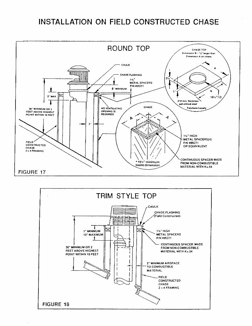
INSTALLATION ON FIELD CONSTRUCTED CHASE
ROUND TOP CHASE TOP
36- MiHIMUM OR 2 FEET ABOVE HIGMESf
METAL SPACERS(4)
OR EQUIVALENT 2 I 4 FRAMING
CONTINUOUS SPACER MADE FROM NOH-COMBUSTIBLE MATE RIAL WllW Kz.54
FIGURE 17
TRIM STYLE TOP
HAS€ FLASHING ield Constructed)
CONTINUOUS SPACER MADE
FEET ABOVE HIGHEST POINT WITHIN 10 FEET
CONSTRUCTED CHASE 2 x 4 FRAMING
FIGURE 18


INSTRUCTIONS FOR OFFSET OF CHIMNEY USlNG ELBOWS TO INSTALL ELBOWS
1 . To achieve desired offset, you may install combina- tions of 12", 18", 36"+ lengths of double wall pipe (see single offset chati and Figure 20A).
2. Chimney weight above offset resls on return elbow. Straps must be securely nailed to rafters or joists. (See Figure 20B).
3. Maximum length of pipe between supports (return elbow or chimney pipe support) is 6' of angled run. Maximum of two 6' angled run sections per chimney system. (Figure 20C).
4. The maximum allowable offset is 30'. Elbows musl be secured to the pipe utilizing a minimum of three screws per joint. Fasten screw through outer pipe slot. Drill 118" pilot hole or use self-drilling screws provided.
FIGURE 208
CHIMNEY DETAIL A PIPE
DETAIL B
FIGURE 20C
OFFSET ELBOW
RETURN ELBOW
OFFSET
OFFSET ELBOW
CHIMNEY
I TYPICAL OFFSET INSTALLATION I

INSTALLING YOUR DOUBLE-WALL CHIMNEY SYSTEM
BEFORE YOU BEGIN INSTALLING YOUR DOUBLE FIRESTOP SPACERS WALL CHIMNEY SYSTEM DETERMINE HOW MUCH PtPE AND ACCESSORIES YOU WILL NEED. SEE firestop spacers are required at each point where the PAGE 6 FOR EXAMPLES O f CHIMNEY AND TERMI- chimney penetrates a floor or ceiling joist space. Their NATION DESIGNS. purpose is twofold: they eslablish and maintain the
required clearance betwekn the chimney and combus- tible materials, and they provide complete separation from one floor space to another floor or attic space, as
Each double-wall chimney section consists of an outer required by most codes. When penetrating a floor or pipe, flue pipe and single-piece wire spacer. The pipe ceiling at an angle, either the 15' or 30' firestop must be sections are not unitized and must be assembled inde- used. (See Figure 22). pendently as the chimney is installed. (Figure 21).
FIGURE 21
INNER PIPE +zsZ( RESTOP SPACER
If pipe passes through a framed opening between floors, install a firestop spacer to the bottom of the joists (Figure 22). When pipe passes into the attic space, install the firestop spacer on the top of the joists (Figure 23) and secure with sheet metal screws or nails.

CHIMNEY PIPE SUPPORT
The chimney pipe support is a double-wall, unitized 12" length of pipe and is designed to relieve the extra weight toad on the fireplace and elbows when high chimneys are installed.
A CHIMNEY SUPPORT IS REQUIRED AFTER A STRAIGHT CHIMNEY RUN OF 35 FEET ABOVE FIRE- PLACE OF RETURN ELBOW. (Figure 24).
FIGURE 24
CHIMNEY 1 B:tpE + SUPPOT
- TOP OF FIREPLACE WlTH STRAIGHT CHIMNEY
STEP 1: When stailing the chimney install the inner pipe section by fitting the male end into the inner fireplace starting collar. Make sure the male end is fully inserted to lock into the lances. (Figure 25).
STEP 2: Fit the outer galvanized pipe with spacer into starting collar on top of fireplace. Rotate the outer pipe until wire spacer locks snap through the outer pipe slots. (Figure 25).
I FIGURE 25
STEP 3: t f you are remodeling, cover exposed pipe and cut a 20" hole on ceiling directly a b v e center of chimney pipe (Use Plumb Bob).
Continue to assemble chimney sections as outlined above, making sure that both inner and outer seaions are locked together.
STEP 4: Determine the location of the hole to be cut in the roof. The roof hole cut-out depends on the pitch of the roof, so refer to the chart on Figure 26.
FIGURE 26
CEILING OPENING CHART
CHIMNEY SET UP
VERTICAL
15"OfFSET
3O0OFFSET
ROOF OPENING CHART
PITCH
FLAT
6/12
12/12
1W12
RECOMMENDED FLASHING
USE FIRESTOP PART NO. 792990
7931 02
792969 1
OPENING
ROOF PITCH
0 - 6/12
6-12/12
12 18/12
118 -24 /12
A
19 112
191/2
19 112
OPENING
FLASHING PART NO.
792975
792976
792977
792978
B
19 112
22114
27
C
19 112
19 t/2
19 112
19 112
0
19 112
22
273/4
35 1/2
43314 24/12 19112

ROOF JOIST SHIELD
STEP 5: After cutting the hole in the roof, uncover the STEP 8: Place flashing into position on unshingled root. pipe and add sections unlil the chimney extends a Hold in position by nailing shingles in place over the minimum of 14 inches above the highest point of the roof flashing edges. cutout. (Figure 27).
STEP 9: Install storm collar on the chimney and push down near the top of the Ilashing. Apply waterproof caulking around the top of the storm collar. (Figure 29).
STEP 6: Slide the roof joist shield over the outer pipe. It must be positioned to cover the joist at ail points around the chimney pipe. It may be necessary to trim the shield slightly to match the slope of the roof. Attach the shield to the joists using the straps provided. (See Figure 27).
-
FIGURE 29
CAULK
STEP 7 : Position the flashing over the chimney and flat on the roof. Mark an outline of the flashing on the roof and remove the flashing, Remove all nails within the outlined area. (Figure 28).
7
FIGURE 28 0
STEP 10: Install terminalion on last section of pipe. There are differenf terminafions approved for this chim- ney system. The Round Top Long is adjustable to compensate for height variations. The Trim Style Top is designed to be used on a chase installation of decora- tive chimney enclosure only. For details, consult the installation instructions of the termination being used. (See Figure 30).
FIGURE 30 1 NOTE: You may wish to caulk seam notches on all joints above the flashing and paint all exposed parts of the chimney with galvanized primer paint. A coat of paint lo match the house may then be applied.

INSTALLING THE GAS LINE STEP 5 : Seal hole around gas line on refractory wall with cement or any other non-combustible
IMPORTANT: Install the gas line before finishing the material. (Figure 33). fireplace. If desired, a decorative gas appliance may be installed. Use only iron pipe, 112" size, and appropriate STEP 6: Finish installation by either capping the gas fittings. When installing gas line, a valve designed for line or attaching a gas log, installation outside the fireplace is required (Figure 31).
CAUTION: WHEN USING THE DECORATIVE
The unit is shipped from Ihe factory ready for installa- tion. The gas line may be installed to enter the fireplace from either side. Refer lo Figure 5 for hole location.
The gas line is intended for connection to a decorative gas appliance incorporating an automatic shutoff device and complying with the Standard for Decorative Gas Appliances for Installation in Vented Fireplaces, ANSl 221.60 Decorative gas appliance should be installed in accordance with the National Fuel Gas Cde . ANSl 2223.1. and NFPA 54.
BEFORE DOING ANYTHING, MAKE SURE THE GAS VALVE LOCATED OUTSIDE YOUR FIREPUCE IS SHUT OFF.
STEP 1: Remove gas line cover. Save screws. Re- move insulation from inside gas conduit sleeve. Save insulation.
t
SLEEVE ,
SCREWS
SIDE -GAS LINE
STEP 2: With gas line conduit sleeve in place strike the back of the refractory using a light punch.
STEP 3: Install a 7 inch minimum nipple to reach inside the fireplace. Allow enough thread to install cap (or elbow i f continuing installation).
STEP 4: Repack insulation into conduit sleeve all around nipple. Replace screws. (Figure 32),
APPLIANCE THE FIREPLACE DAMPER MUST BE SET IN THE FULLY OPEN POSITION.
THIS INSTALLATION IS NOT LISTED BY UNDERWRITERS LABORATORIES, INC,"
RADCO LAB. in accordance wIth ICBO require- ments and is approved for use with this fireplace model.
INSTALLATION OF GAS LOG LIGHTER IF YOUR FIREPLACE IS PROVIDED WITH A GAS LINE FOR ATTACHMENT TO A GAS LOG LIGHTER, PLEASE FOLLOW THESE INSTRUCTIONS CARE- FULLY.
1) BEFORE DOING ANYTHING, MAKE SURE THE GAS VALVE LOCATED OUTSIDE YOUR FIRE- PLACE IS SHUT OFF.
2) REMOVE THE CAP AT END OF GAS PIPELINE PROTRUDING FROM SlDE OF THE REFRAC- TORY. (SEE FIG. 33).
3) CONNECT FITTINGS: TWO - 112 INCH DIA. 45" ELBOW ONE - 112 INCH DIA. CLOSE NIPPLE
4) INSTALL GAS LOG LIGHTER MAX. 24' LONG. 1/2 INCH DIAMETER TO ELBOW. (SEE FlG.33)
GAS LOG LIGHTER MUST BE INSTALLED FLUSH TO M E HEARTH FLOOR OF YOUR APPLIANCE. DO NOT ELEVATE GAS LOG LIGHTER. YOUR GAS LOG LIGHTER IS NOW READY FOR USE.

TEST FOR GAS LEAKS 1 All gas piping and connections must be tested for leaks after the installation is completed. Be sure gas valve is turned on. Apply soap suds solution to all connections and joints. If bubbles appear, leaks can be detected and corrected. 00 NOT use a match or open flame of any kind to test for leaks. Never operate any appliance with leaky connections.
CAUTION:
1) MAKE SURE THE DAMPER tN YOUR FIREPLACE IS SET IN A PERMANENTLY OPEN POSITION IN CASE THE GAS VALVE IS TURNED ON BY ACCI- DENT, BY FOLLOWING THIS SIMPLE INSTRUC- TION, YOU WILL PREVENT GAS FROM ESCAP- ING INTO YOUR LlVtNG ROOM AND CAUSING POSSIBLE SERIOUS INJURIES OR DAMAGE TO YOUR DWELLING.
2) TURN ON GAS VALVE.
3) LIGHT LOG LIGHTER WlTH A MATCH. USE COMMON SENSE IN LIGHTING. FOR YOUR SAFETY, NEVER USE 0 8 STORE GASOLINE OR OTHER FLAMMABLE LIQUIDS IN THlS OR ANY OTHER APPLIANCE.
4) AFTER YOUR LOG HAS STARTED TO BURN, TURN OFF GAS VALVE. THE KEY USED FOR TURNING THE GAS VALVE ONlOFF SHOULD BE KEPT OUT OF REACH OF CHILDREN.
5) TO RESTART, REPEAT RELIGHTING INSTRUC- TIONS.
6) KEEP ORIFICES CLEAN FROM ASHES AND DEBRIS. THlS WlLL PREVENT THE ORIFICES FROM BECOMING CLOGGED. CLEAN IT ONLY WHEN COLD.
NEVER ALLOW GAS TO RUN UNLIGHTED. IF THlS HAPPENS, THERE IS A POSSIBILITY OF GAS ES- CAPING INTO YOUR LIVING AREA. IF YOU SMELL GAS, OPEN WINDOWS, EXTINGUISH ANY OPEN FLAME AND IMMEDIATELY CALL YOUR LOCAL GAS SUPPLIER. NEVER LEAVE CHILDREN ALONE NEAR THE APPLIANCE WHEN IN USE. REFER TO IN- STRUCTION MANUAL FOR OTHER INSTRUCTION DETAILS.
KEEP THESE INSTRUCTIONS FOR FUTURE REF- ERENCE.
COLD CLIMATE INSTALLATION If you live in a cold climate, it is especially important to seal all cracks around fireplace with non-combustible material and wherever cold air could enter the room.
Surround material must be caulked where it meets the black metal facing of the fireplace to avoid cold air intrusion. Use only non-combustible caulking material on fireplace facing to seal.
In areas of extreme cold, it is recommended that the outer wall of the chase be insulated. This will reduce the possibility of cold air convection currents on the fire- place. NEVER use blown-in type of insulation as this could plug the holes at the base of the unit and interlere with the thermal syphoning action necessary to keep the chimney cool.
FINISHING THE FIREPLACE
FIREPLACE FACING
When selecting the finish material for your fireplace, i t is important to remember the following: THE BLACK FACE OF THE FIREPLACE MUST NOT BE COVERED WlTH ANY TYPE OF COMBUSTIBLE MATERIAL.
Non-combustible facing material such as tile, brick, glass, etc. may overlap the black face of the fireplace. Be sure to use non-combustible heat resistant mortar or adhesive when attaching to fireplace face. The face of the fireplace may be painted to match the mom decor provided you use a heat resistant paint.
NOTE: DECORATIVE FACING MUST NOT EXTEND INTO THE FIREPLACE OPENING AT ALL, BECAUSE IT WlLL INTERFERE WlTH THE OPERATION OF THE GLASS DOORS. THE GLASS DOOR MOUNTS OVER M E FACING MATERIAL. THE MOUNTING HARD- WARE PROVIDED WILL ALLOW INSTALLATION TO FACING MATERIAL OF O" TO 5 IN WIDTH.

HEARTH EXTENSION: EXAMPLE OF DETERMING HEARTH EXTENSION EQUIVALENT
If there is a combustible floor construction in front of the fireplace, a heaRh extension is required to prolect it. The hearth extension, as shown in Figure 35,must be a minimum of 20" deep by 65" wide and extend a minimum of 12" beyond each side of the fireplace opening.
FIGURE 35
The hearth extension must be made from a non-com- bustible inorganic material with a thermal conductivity, K of .27 or less. The thermal conductivity, K or thermal resistance. R of materials can usually be obtained from the manulacturer. The factors are related by the for- mula K = -,!, The thickness required for various common materials and their factors are shown in Figure 36.
FIGURE 36 - COMMON MATERIALS AND THEIR FACTORS
To determine the thickness required for any material: K new material x 1" = Thickness Required
.84
Example for Insulating Board-K-FAG 19 (K trom Figure 36).
Whatever the material used, sufficient thickness must be laid down to maintain an equivalent K factor.
The thermal insulating layer may be covered by any non-combustible material such as metal, tile, slate, brick, glass, concrete, marble, or stone. When using a low density insulating material a supporting metat cover such as shown in Figure 37 should be fabricated and installed. NOTE: Some non-combustible coverings such as metal, slate, sandstone and marble are rela- tively gcad conductors of heat and rnusl be used in combination with the more thermally resistant materi- als.
In finishing up the hearlh extension, be sure to fasten it securely to the floor to prevent shifting, and seal the gap between the fireplace frame and the hearlh extension with a non-combustible material (see Figures 38 & 39).
METAL COVER DESIGN CONSlSTS OF A TOP AND 4 SIDES
AS REQUIRED BY DESIGN NOTCH CORNERS THEN
BEND FLANGES $0'.
65" MIN.
MATERIAL 318 MIN. THlCKNESS GALVANIZE0 2O"MIN. OR ALUMINUM STEEL
FIGURE 37- METAL COVER CONSTRUCTION
NON-COMBUSTIBLE DECORATIVE COVERING:
Should be at least 3/8" thick and meet Iccal building code requirements. The finished height of the hearth extension must not block the inlet grille at the bottom of the fireplace.

IV. OPERATfNG INSTRUCTIONS
DAMPER CONTROL LEVER
The damper control lever located inside the lop front of the firebox has been engineered lo provide safe opera- tion of your fireplace. Do not close the damper in an attempt to reduce a large fire. To do so may cause a potential smoke hazard, just as any fuel-burning appli- ance would do if not properly exhausted. If you forget to open the damper before you start your fire (you will know immediately by the smoke entering your home,)! simply move the damper fever from its closed position notch to the open posifion (Figure 42).
The fireplace flue damper must always remain open unlil the fire is totally out. Partially burned logs can appear lo be out even when still burning and giving off dangerous gases. If the damper is closed too soon, these gases may escape info the room.
1 FIGURE 42 1
FIREPLACE GRATE:
This unit has been equipped with a gray; to keep the operation of your fireplace efficient and safe. Do not attempt to defeat its purpose. The size and position of the grate was engineered to give the ideal combustion characteristics for the lire. By keeping your @s within the grate and not on the hearth, you will prevent the chance of a log "spill" or roll out of the fireplace. DO NOT OVERLOAD THE FIREPLACE. Piling excessive wood on your grate will not increase efficiency and could possibly cause smoke to enter your room Keep the hearth area under the grate free of excessive ash bvild- up to allow a free flow of air for the fire.
OUTSIDE AIR CONTROL
The outside combuslion air kit is an oplional accessory installed at the time of fireplace installation. I t aids greatly in the efficient operation of your fireplace. It should be opened during operation as shown in Figure 43.
OPEN \
1 FIGURE 43 I Outside air drawn into the fireplace supplies air to the fire for combustion. When the fireplace is not in use, close the air gate lo prevent cold air from entering your home. For outside wall installation check the intake screen inside eyebrow periodically to insure it is clear of debris,

FIREPLACE AND HEARTH EXTENSION ON COMBUSTIBLE F LDOR
O P n O H U NOM-COMBUS DECORATIVE CWERIAG
COUBVSTlSLE FLOOR COVERIHC
METAL SAFETY H U R M EXTEHSIOH
Fl G U RE 38 OR EOUIVALEUT
I f a raised headh is constructed, the hearth must be buitt out of completely noncombustible materials. The height of the raised hearth cannot extend above the bottom edge of the fireplace opening.
1 Lrrrau H u m D m w s l O W -SAFEr?
FIGURE 39 OR EaUlVMENT Sf"P-OFFSET - WARNING: HEARTH EXTENSION IS TO BE INSTALLED ONLY AS ILLUSTRATED. FIGURES 35 THRU 39 SHOW OP- TIONAL INSTALLATIONS.
MANTLES 1 i
FINISHED WALL
COMBUSTIBLE - FALSE HEADER
NON-COMBUSTIBLE _/ DECORATIVE FACING (DO NOT OVERLAP / SEAL AMY GAP WITH THE OPENING) STEEL NON-COMBUSTIBLE
LlKTEL MATERIAL
I FIGURE 40-NON COMBUSTIBLE FACING ) Combustible mantles may be safely installed provided they do not project beyond safety zone as illustrated in Figure 40.
NOTE: Use an "L" shaped piece of metal (lintel) across the top of the fireplace opening when a non-combustible material is used on the face of the fireplace. It can be attached to the face of the fireplace with screws (see Figure 40).
MANTLE SURROUNDS Often a decorative surround or verlical rtion of the P" mantle is desired. If this is constructed o any wmbus- tible material it must be within the safe zone indicated in Figure 40.
BLACK PORTION OF FRAME NOT TO BE COVERED W I M COMBUSTlBLE MATERIALS
r
v EXAMPLE OF COMBUSnBLE MANTLE WITHIN SAFElY ZONE
FIGURE 41- - If the fireplace design incorporates a mantle with side legs, book shelves, wood bins, closets, etc., Ihese should not project beyond the safety zone shown in figure 41.

Read operation and warranty manuals thoroughly before installing and using this fireplace.
DO'S AND DON'TS This Fireplace is intended for use with solid wood fuel only. Keep base of fireplace clean of excess ash accumulation to
prevent grate "burnout'.
c When installing this fireplace in cold climate areas be sure to follow the cold climate installation instruclions outtined in Keep the fire screen closed at all times when burning, !his booklet. except when adding fuel.
Check the hearth for cracks and damage. Because the 4 WARNING: THE OPENLNGS OF THE COLLAR AROUND firebrick refractory is repeatedly heated and cooled, this can THE BASE O F THE CHIMNEY AT THE TOP OF THE cause hairline cracks to form. This Is normal and does not FIREPLACE MUST NOT BE OBSTRUCTED. NEVER USE damage the fireplace. If, however, a crack should become BLOWN INSULATION TO FILL THE CHIMNEY ENCLO- large (1116* wide or larger). refractory should be replaced. SURE.
Have repairs done by a qualified servlce technician. Do not overload the grate; to do so could cause smoke to enter the room.
r Open damper lo ensure proper operation.
Be sure outside air gate is open before starting your fire. Ventilating fans, central heating systems, and exhaust fans can cause fireplaces to smoke by stealing the available combustion air needed for burning the wood in your fire- place.
'Cure* the refractory lining by building only small fires the first two or three times you use the tireplace. The refractory sides and bottom are made from a combination of materials including refractory cement and water. Large roaring fires built on 'uncured" refractory could generate steam within the refractory and cause cracks.
Do not allow ashes directly under the burning logs to build up to a point where they hinder the air flow.
Do not block bottom vent or louvre.
Do not burn Large amounls of waste paper or cardboard in your fireplace.
Do not burn wood products with synthetic binders like artifical logs or plywood, as these produce abnormally high temperatures,
c Never use gasoline, gasoline-type lantern fuel. kerosene. Keep area in front of fireplace clear of combustible maleri- charcoal lighter fluid, or similar liquids to start or 'freshen als such as drapes, paper products, wood storage, furni- up" a fire in this fireplace. Keep all such liquids well away ture. etc. from the lireplace while it is in use.
Creosote- Formation and Need for Removal.
When wood is burned slowly, it produces tar and other organic vapors, which combine with expelled moisture lo form creosote. The creosote vapors condense in the rela- tively cool chimney flue of a slow-burning fire. As a result. creosote residue accumulales on the flue lining. When ignited this creosote makes it an extremely hot lire.
The chimney shoufd be inspected at least twice a year during the heating season to determine if a creosote buildup has occured.
Never close the damper until you are certain that there are no warm embers.
DISPOSAL OF ASHES: Ashes should be placed in a metal container with a tight-fining lid. The closed container of ashes should be placed on a noncombustible lloor or on the ground, well away from all combustible materials, pending final disposal. If the ashes are disposed ol by burial in soil or otherwise locally dispersed, they should be retained in the dosed container until all cinders have thoroughly cooled.
If creosote has accumulated it should be removed to reduce REFERENCE DOCUMENTS: the risk of a chimney fire.
1. MARC0 Woodburning Fireplace Warranty and Operation Manual, PIN 181536.
To prevent excessive creosote build-up, use only dry, sea- soned wood. .
2. Glass Door Kit Installation Instruclions.
Regular inspection and cleaning of !he creosote (soot) build-up in your chimney is imporlant for the safe operation 3 lo" Classic Adjustable Round Terminations Installation o l your fireplace. Consult your warranty manual for cban- lnstrvclions PIN 181 690. ing tnstructions.
When tire is actively burning, Open door !or tTiaxhlum heat 4. 10- Trim Style Termination, PIN 181689. . . .

THIS FIREPLACE IS NOT INTENDED TO BE . - USED WITH ANY COMPONENTS OTHER '
THAN THOSE SPECIFIED IN THIS MANUAL
COMPONENT PARTS U.L. LISTED PARTS FOR 10" DOUBLE WALL FLUE SYSTEM
r
793131(30E - 10D) STORM COLLAR 793112{SC - 100)
FIRESTOP SPACERS: 792990 (FS-100) - FLAT
15" ELBOW SET 792969 (FS30-100) - 30' (OFFSET ELBOW)
FLASHINGS: 792975(6F - IOD) 6 - 611 2 79297qlZF - lOD) 6 - 12/12 7 9 2 9 n ( i e ~ - loo) i 2 - 18/12 7931 27 36- 792978(24F - 100) f 8 - 24/12 (DOUBLE WALL PIPE)
793125 ROOF JOIST SHIELD r a - ( w u e ~ ~ WALL PIPE) PIN 792992
A
,+/ ' *.. 793l29(12 CPS - 100) ROUND TERMINATIONS @ PIPE CHIMNEY SUPPORT '
79290 1 (RTL - 10) 7931 06 1
(BTLC - 1 OD) L 793096 TRIM STYLE TOPITST - 1 OD)
REPLACEMENT PARTS TRADITIONAL - 792870
hrl Number Grate 498728
Relraclory: Hem 164610 Back 16461 f Side 164612 Screen 161110
TUDOR - 792871 Part Number
Gale 499340 Refractory:
Hearlh 164617 Back 164620 Side LH 164618 Si& RH 164619 Screen 161110
CUSTOM - 792872 Part Number
Grate 493341 Relractory:
Hearth 164613 Back 16461 4 Side LH 164615 Sick RH 164616 Screen 161110
Custom Glass Door Kit Square framed Glass Door 793420 Lef! Hand Door 49923 1 Right Hand Door 499232
HOW TO ORDER REPAIR PARTS
1 . Order repair parts from the Dealer through whom you 3. When remittance is sent with the order, include purchased the fireplace, if possible. enough for transportation.
2. Be sure to give the Part Number, the Name of the Part, 4. There is a mhimurn invoice charge of $10,00 plus and the Fireplace Stock Number. The Stock Number postage for each order. is printed on the UL Rating Plate, located in the upper right hand corner behind the screen. 5. Aft parts are subject to change without notice.

MARC0 ME., INC. hA, M d P C ! ,-,.m I-.. . . . . . .A , - . I - . A e. -..* ... .-,. r . . ..-.
