operating manual - fujitsumanuals.ts.fujitsu.com/file/3660/400-200-ba-en.pdf · the hard disk...
TRANSCRIPT

SE
RV
ER
SE
RV
ER
SE
RV
ER
SE
RV
ER
PR IMERGY 400 /200PR IMERGY 400 /200PR IMERGY 400 /200PR IMERGY 400 /200SERVER SYSTEMS
OPERATING MANUALOPERATING MANUALOPERATING MANUALOPERATING MANUAL

Is there ...
... any technical problem or otherquestion you need clarified?
Please contact:• one of our service partners• your sales partner• your sales outlet
The addresses of your service partners are contained in the guarantee booklet or in the serviceaddress booklet.
The latest information on our products, tips, updates, etc., can be found on the Internet under:http://www.fujitsu-siemens.com


Dieses Handbuch wurde auf Recycling-Papier gedruckt.This manual has been printed on recycled paper.Ce manuel est imprimé sur du papier recyclé.Este manual ha sido impreso sobre papel reciclado.Questo manuale è stato stampato su carta da riciclaggio.Denna handbok är tryckt på recyclingpapper.Dit handboek werd op recycling-papier gedrukt.
Herausgegeben von/Published byFujitsu Siemens Computers GmbH
Bestell-Nr./Order No.: A26361-K632-Z100-1-7619A26361-K632-Z100-1-7619A26361-K632-Z100-1-7619A26361-K632-Z100-1-7619Printed in the Federal Republic of GermanyAG 0400 04/00
A26361-K632-Z100-1-7619
PRIMERGY 400/200 OPERATING MANUAL

PRIMERGY 400/200
OPERATING MANUAL
Introduction
Important notes
Installation
Preparation for use andoperation
Property and dataprotection
Troubleshooting and tips
System expansions fortower server
System expansions forrack server
Technical data
Index
April 2000 edition

Intel and Pentium are registered trademarks of Intel Corporation, USA.
NetWare and Novell are registered trademarks of Novell, Inc.
SCO and SCO Unix are registered trademarks of Santa Cruz Operation.
Windows is a registered trademark and Windows NT is a trademark of Microsoft Corporation.
All other trademarks referenced are trademarks or registered trademarks of their respectiveowners, whose protected rights are acknowledged.
Copyright � Fujitsu Siemens Computers GmbH 2000
All rights, including rights of translation, reproduction by printing, copying or similar methods,even of parts are reserved.
Offenders will be liable for damages.
All rights, including rights created by patent grant or registration of a utility model or design,are reserved.
Delivery subject to availability. Right of technical modification reserved.

A26361-K632-Z100-1-7619
ContentsIntroduction .....................................................................................................................................1Features ............................................................................................................................................1Notational conventions ......................................................................................................................3
Important notes ...............................................................................................................................5Safety ................................................................................................................................................5Manufacturer’s notes .........................................................................................................................6
CE certificate .............................................................................................................................6FCC Class A Compliance Statement .........................................................................................7
Power cord selection .........................................................................................................................8For the United States and Canada.....................................................................................8For the United Kingdom.....................................................................................................9
Disposal and recycling.............................................................................................................10Transporting the server....................................................................................................................10
Installation .....................................................................................................................................11Instructions on connecting and disconnecting cables ......................................................................11Installing the tower server................................................................................................................12
Connecting devices to the server.............................................................................................13Connecting the monitor to the line voltage ...............................................................................14Connecting the server to the line voltage.................................................................................14
Installing the rack server..................................................................................................................17Fit assembly kit and rack-mount the server .............................................................................17Mounting cable guides and routing cables ...............................................................................21Connecting devices to the server.............................................................................................24Connecting the server to the line voltage.................................................................................25
Preparation for use and operation ...............................................................................................27Unlocking tower server ....................................................................................................................27Controls and indicators....................................................................................................................29Switching the server on and off .......................................................................................................31Configuring the server and installing the operating system..............................................................33
ServerStart ..............................................................................................................................33Locking tower server .......................................................................................................................34Service compartment in tower server ..............................................................................................35Cleaning the server .........................................................................................................................35
Property and data protection........................................................................................................37BIOS Setup security functions .........................................................................................................37
Troubleshooting and tips..............................................................................................................39Power-on indicator remains dark after you have switched on your device .......................................39The server switches itself off ...........................................................................................................39The screen stays blank....................................................................................................................39Flickering stripes on the monitor screen ..........................................................................................40No screen display or display drifts ...................................................................................................40No mouse pointer displayed on the screen......................................................................................41The floppy disk cannot be read or written ........................................................................................41Time and/or date is not correct ........................................................................................................41System will not boot after installing a new hard disk drive ...............................................................41Drives are reported as "dead" at system boot..................................................................................42Added drive is reported as defective................................................................................................42Error messages on the screen.........................................................................................................42

Contents
A26361-K632-Z100-1-7619
System expansions for tower server........................................................................................... 43Opening the server ......................................................................................................................... 43Assembling the server .................................................................................................................... 46SCSI hard disk drives ..................................................................................................................... 48
Installing a SCSI hard disk drive ............................................................................................. 49Removing a SCSI hard disk drive............................................................................................ 50
RemoteView chipdisk...................................................................................................................... 51Installing a RemoteView chipdisk ............................................................................................ 51Removing a RemoteView chipdisk .......................................................................................... 53
Accessible drives ............................................................................................................................ 55Installing an accessible 5 ¼-inch drive .................................................................................... 55Removing an accessible 5 ¼-inch drive .................................................................................. 57Changing the floppy disk drive ................................................................................................ 58
Boards ............................................................................................................................................ 58Installing a board..................................................................................................................... 59Removing a board................................................................................................................... 60
Power supply module...................................................................................................................... 60Installing the power supply module ......................................................................................... 61Removing the power supply module........................................................................................ 63
Exchanging the fan ......................................................................................................................... 65Extensions on the system board ..................................................................................................... 66
System expansions for rack server ............................................................................................. 67Opening the server ......................................................................................................................... 67Assembling the server .................................................................................................................... 69Accessible drives ............................................................................................................................ 72
Installing an accessible 5 ¼-inch drive .................................................................................... 72Removing an accessible 5 ¼-inch drive .................................................................................. 74Changing the floppy disk drive ................................................................................................ 76
Technical data............................................................................................................................... 77
Index .............................................................................................................................................. 79

A26361-K632-Z100-1-7619 1
IntroductionThe PRIMERGY400 and 200 are Intel-based servers for small and medium-sized networks and canbe used as tower or rack servers. Conversion to the respective other version is possible with anoptional conversion kit.
The PRIMERGY 400 and 200 servers offer a high level of failure safety and availability throughhighly developed hardware and software components. Hardware components include hot-replacecarriers, the ServerView server management , PDA (Prefailure Detection and Analyzing) and ASR&R(Automatic Server Reconfiguration and Restart).
Security functions in the BIOS Setup and on the system board protect the data on the server againstmanipulation. As a tower server, the lockable door and an anti-theft protection device on the back ofthe unit offer additional protection. As a rack server, the lockable door of the rack offers additionalsafety.
This Operating Manual tells you how to put your server into operation, how to operate it in daily useand how to expand your server. Work steps which are identical for the tower and rack version areonly described for the tower version.
Further information is provided:• in the manual "Safety, Guarantee and Ergonomics"• in the Technical Manual of the system board• in the manual for the BIOS Setup• in the Technical Manual for the 19-inch rack (Rack-Server)• in the manual for the monitor• in the manual for the ServerView server management• in the manual for the Remote Test and Diagnosis System RemoteView• in the documentation for the boards and drives• in the documentation of your operating system• in the information files of your operating system
FeaturesSystem board
System boards with various features are available for the PRIMERGY 400 and 200 server systemsto suit a wide range of requirements. For a description of the features of the system board integratedin your server, please see the manuals System Board for the hardware and BIOS Setup for thesoftware.
Hard disk subsystem
The hard disk subsystem comprises four or six 3 ½-inch hard disk carriers and the SCSI platter.Each hard disk carrier can accommodate an SCSI hard disk drive with an SCA (Single ConnectorAttachment) interface and a maximum height of 1.6 inches or 1 inch. The module is connected tothe SCSI disk without cables via the SCA interface. This allows the hard disk drive to be simplyplugged in or pulled out.
The hard disk subsystem is designed for 80 MHz SCSI. The version with four 3 ½-inch hard diskcarriers is a 1-channel, the version with six 3 ½-inch hard disk carriers can be configured as 2-channel with two hard disks or as 1-channel with six hard disks. The hard disk subsystem can becontrolled by a standard controller or by a disk array controller (DAC). If the server is equipped witha DAC, defective hard disk drives can also be replaced during operation (hot replace).

Introduction Features
2 A26361-K632-Z100-1-7619
Power supply
The server can be equipped with a permanently installed power supply (standard) or with a plug-inpower supply (hot plug) consisting of one or two modules. With two power supply modules theserver is equipped with a redundant power supply. If a defect occurs in one module, the respectiveother module ensures unimpaired further operation. The defective module can be replaced duringoperation.
High level of availability and failure protection
When accessing stored data, 1-bit-errors in the main memory are automatically recognized andcorrected (EDC = Error Detection and Correction). The patented memory scrubbing function regularlystarts up the EDC mechanism and thus ensures continuous data integrity. ASR&R tunes outdefective system components during an automatic system reboot. The Prefailure Detection andAnalyzing Technology reports the threat of system errors or problems to the system administrator sothat preventative measures can be taken. The optional disk array controller increases systemavailability and supports the RAID levels 0, 1 and 5. The hot-replace-capable hard disks provideadditional protection.
Server management
Server management is implemented with the aid of the supplied ServerView software and PDA(Prefailure Detection and Analyzing) technology from Fujitsu Siemens. The PDA analyzes andmonitors all components relevant to system reliability, thus enabling early detection of overloadsituations and appropriate counter-measures.
ServerView enables the management of all PRIMERGY servers in the network via a central console.Here ServerView supports the following functions:
• Temperature monitoring of the CPU and the surrounding area.• Timer-controlled switch-on (Timer)• Remote switch-on (Ring Indicator)• Watchdog timer for Automatic Server Reconfiguration and Restart (ASR&R) in the event of
failure of memory modules or processors.• Pager message when rebooting system following an error• Monitoring ISA and PCI bus loading• End-of-Life monitoring of the fans with timely indication before failure• Watchdog timer for operating system monitoring and application monitoring• Detailed status and error reports for bus systems, processors and main memory• Statistics for service technicians (operating hours counter, counter for switch-on/switch-off
cycles)• Storage of 50 error messages in the non-volatile SRAM memory
Further information on the ServerView server management is provided in the associateddocumentation.
ServerStart
You can configure the PRIMERGY server quickly and purposefully with the ServerStart softwareprovided. User-guided menus are available for installing the server operating systems.
Service and Support
PRIMERGY devices are service-friendly and modular, thus enabling quick and simple maintenance.The flash EPROM program supplied with the Fujitsu Siemens utilities supports fast BIOS update.With the optional Remote Test and Diagnosis System RemoteView, long-distance maintenance andservice (remote) can also be performed on the servers of the PRIMERGY 400 series.

Notational conventions Introduction
A26361-K632-Z100-1-7619 3
Notational conventionsThe meanings of the symbols and fonts used in this manual are as follows:
!Pay particular attention to texts marked with this symbol. Failure to observe this warningendangers your life, destroys the system, or may lead to loss of data.
iSupplementary information, remarks and tips follow this symbol.
Ê Texts which follow this symbol describe activities that must be performed in the order shown.
Texts in italics indicate commands or menu items.
"Quotation marks" indicate names of chapters and terms that are being emphasized.


A26361-K632-Z100-1-7619 5
Important notesIn this chapter you will find information regarding safety which it is essential to take note of whenworking with your server. The manufacturer's notes contain helpful information on your server.
SafetyThis device complies with the pertinent safety regulations for information technology, includingelectric office machines for use in an office environment. If you have any questions, contact yoursales outlet or our customer service center.
The safety information is contained in the manual " Safety, Guarantee and Ergonomics". Thefollowing outlines some of the most important safety information:
• During installation and before operating the device, please observe the instructions onenvironmental conditions in the chapter entitled "Technical data" as well as the instructions inthe chapter "Installation".
• The ON/OFF switch and the main switch do not disconnect the server from the line voltage. Todisconnect the line voltage completely, remove the power plug from the grounded power outlet.
• When cleaning the Server, observe the relevant notes in the chapter "Preparation for use andoperation".
• When connecting and disconnecting cables, observe the relevant notes in the chapter"Installation".
• Replace the lithium battery on the system board in accordance with the instructions in theTechnical Manual for the system board.
• The CD-ROM drive contains a light-emitting diode (LED), classified according to IEC 825-1:1993:LASER CLASS 1.
• Keep this Operating Manual together with your device. If you pass on the device to thirdparties, you should include this manual.
• Caution: components on the system board can get very hot.
• Please check whether the server is set to the local line voltage (see chapter "Installation"section "Connecting the server to the line voltage").

Important notes Manufacturer's notes
6 A26361-K632-Z100-1-7619
Boards with electrostatic sensitive devices (ESD) may be identified by labels.
When you handle boards fitted with ESDs, you must observe the following points under allcircumstances:
• You must always discharge yourself (e. g. by touching a grounded object) before working.
• The equipment and tools you use must be free of static charges.
• Pull out the power plug before inserting or pulling out boards containing ESDs.
• Always hold boards with ESDs by their edges.
• Never touch pins or conductors on boards fitted with ESDs.
Manufacturer's notes
CE certificateThe shipped version of this device complies with the requirements of the EEC directives89/336/EEC "Electromagnetic compatibility" and 73/23/EEC "Low voltage directive".

Manufacturer's notes Important notes
A26361-K632-Z100-1-7619 7
FCC Class A Compliance StatementIf there is an FCC statement on the device, then:The following statement applies to the products covered in this manual, unless otherwise specifiedherein. The statement for other products will appear in the accompanying documentation.
NOTE:
This equipment has been tested and found to comply with the limits for a "Class A" digital device,pursuant to Part 15 of the FCC rules and meets all requirements of the Canadian Interference-Causing Equipment Regulations. These limits are designed to provide reasonable protection againstharmful interference in a residential installation. This equipment generates, uses and can radiateradio frequency energy and, if not installed and used in strict accordance with the instructions, maycause harmful interference to radio communications. However, there is no guarantee thatinterference will not occur in a particular installation. If this equipment does cause harmfulinterference to radio or television reception, which can be determined by turning the equipment offand on, the user is encouraged to try to correct the interference by one or more of the followingmeasures:
· Reorient or relocate the receiving antenna.· Increase the separation between equipment and the receiver.· Connect the equipment into an outlet on a circuit different from that to which the receiver is
connected.· Consult the dealer or an experienced radio/TV technician for help.
Fujitsu Siemens Computers GmbH is not responsible for any radio or television interference causedby unauthorized modifications of this equipment or the substitution or attachment of connectingcables and equipment other than those specified by Fujitsu Siemens Computers GmbH. Thecorrection of interference caused by such unauthorized modification, substitution or attachment willbe the responsibility of the user.
The use of shielded I/O cables is required when connecting this equipment to any and all optionalperipheral or host devices. Failure to do so may violate FCC rules.

Important notes Power cord selection
8 A26361-K632-Z100-1-7619
Power cord selectionThe power cord for this unit has been packedseparately and has been selected for use in theappropriate country. It must be used to preventelectric shock. Use the following guidelines if itis necessary to replace the original cord set.
The female receptacle of the cord set must meetCEE-22 requirements (see Figure).
For the United States and Canada
Use a UL listed and CSA labeled cord set consisting of a three-conductor cord with a maximumlength of 15 feet.
For units that stand on a desk or table, type SVT or SJT cord sets shall be used.
For units that stand on floor, only SJT type cord sets shall be used.
The cord set must be selected according to the current rating for your unit. Please consult Table Afor the selection criteria for power cords used in the United States and Canada.
Table A:
Cord Type Size of Conductorsin Cord
Maximum CurrentRating of Unit
SJT 18 AWG16 AWG14 AWG
10 Amps12 Amps12 Amps
SVT 18 AWG17 AWG
10 Amps12 Amps
For units set at 115 V:
use a parallel blade, grounding type attachmentplug rated 15 A, 125 V.
For units set at 230 V (domestic use):
use a tandem blade, grounding type attachmentplug rated 15 A, 250 V.

Power cord selection Important notes
A26361-K632-Z100-1-7619 9
For units set at 230 V (outside of the United States and Canada):
use a cord set consisting of a minimum AWG according to Table A and a grounding type attachmentplug rated 15 A, 250 V. The cord set should have the appropriate safety approvals for the country inwhich the equipment will be installed and should be marked HAR.
For the United Kingdom
Should the plug on the flexible cord not be of the type for your socket outlets, do not use an adapterbut remove the plug from the cord and discard. Carefully prepare the end of the supply cord and fit asuitable plug.
WARNING
THIS APPLIANCE MUST BE EARTHED
IMPORTANT
The wires in this mains lead are colored in accordance with the following code:
Green and Yellow: Earth
Blue: Neutral
Brown: Live
As the colors of the wires in the mains lead of this appliance may not correspond with the coloredmarkings identifying the terminals in your plug, proceed as follows:
· The wire which is colored Green and Yellow must be connected to the terminal in the plugwhich is marked with the letter E or by the earth symbol or colored Green or Green and Yellow.
· The wire which is colored Blue must be connected to the terminal which is marked with theletter N or colored Black.
· The wire which is colored Brown must be connected to the terminal which is marked with theletter L or colored Red.

Important notes Transporting the server
10 A26361-K632-Z100-1-7619
Disposal and recyclingThis device has been manufactured to the greatest possible degree from materials which can berecycled or disposed of in a manner that is not environmentally damaging. The device is taken backafter use, to be recycled, provided that it is returned in a condition that is the result of normal use.Any components not reclaimed will be disposed of in an environmentally acceptable manner.
Do not throw lithium batteries or accumulators into the trashcan. They must be disposed of inaccordance with local regulations concerning special waste.
If you have any questions on disposal, please contact your local office, our customer service center,or:
Fujitsu Siemens Computers GmbHRecyclingcenterD-33106 Paderborn
Tel.: +49 5251 818010Fax: +49 5251 818015
Transporting the server
!Transport the server only in its original packaging or in a packaging which protects it fromknocks and jolts, to the new site. Do not unpack the server until all transportationmaneuvers are completed.
If you need to lift or transport the server, ask someone to help you.

A26361-K632-Z100-1-7619 11
Installation
!Please take note of the safety information in the chapter "Important notes".
It is recommended not to throw away the original packaging material! It may be required fortransportation at some later date.
Ê Unpack all the individual parts.
Ê Check the delivery for damage incurred during transportation.
Ê Check whether the delivery agrees with the details in the delivery note.
Ê Check whether all necessary details have been entered on the first page of the guaranteecoupon booklet.
The model rating plate is located on the left-hand side of the server.
Should you discover that the delivery does not correspond to the delivery note, notify your supplierimmediately.
Instructions on connecting and disconnecting cables
!Be sure to read the documentation on the external devices before connecting them.
Do not connect or disconnect cables during a thunderstorm.
Always take hold of the actual plug body. Never unplug a cable by pulling the cable itself.
Connect and disconnect the cables in the order described below.
Connecting cables
• Turn off all power and equipment switches.
• Pull all power plugs out of the grounded power outlets.
• Plug all cables into the server and peripherals.
• Plug all data communication cables into the utility sockets.
• Plug all power cables into the grounded power outlets.
Disconnecting cables
• Turn off all power and equipment switches.
• Pull all power plugs out of the grounded power outlets.
• Unplug all data communication cables from the utility sockets.
• Disconnect the relevant cables at the server and at the peripherals.

Installation Installing the tower server
12 A26361-K632-Z100-1-7619
Installing the tower server
!Do not expose the server to extreme environmental conditions (see chapter "Technicaldata"). Protect it from dust, humidity and heat.
There must be a clearance of at least 200 mm in front of and behind the server to ensureadequate ventilation. Do not cover the ventilation areas of the monitor and the server.
Prepare the keyboard
Ê Plug the appropriate connector of the keyboard cable into the socket on the underside of thekeyboard as shown in the illustration above.

Installing the tower server Installation
A26361-K632-Z100-1-7619 13
Connecting devices to the serverThe ports for external devices are on the rear of the server. Which ports are available on your serverdepend on the boards installed. The standard ports are indicated by symbols.
�
�
�
�
�
�
�
�
�
�
1 = Monitor port2 = Serial port 13 = Keyboard port4 = Parallel port5 = Serial port 2
6 = PS/2 mouse port7 = CAN-bus port8 = Slots for additional ports9 = Slots for additional ports
Ê Connect the data cables at the server and peripherals.
iSome of the devices that you connect require special drivers (see the documentation forthe connected device).
If a separate graphics card is used in a slot, then the graphics controller on the system board isautomatically deactivated. The related monitor port (1) cannot be used. Instead, connect the datacable of the monitor to the monitor port of the graphics card.

Installation Installing the tower server
14 A26361-K632-Z100-1-7619
Connecting the monitor to the line voltageServers with the standard power supply enable the power cable of the monitor to be connected tothe server.
�
�
Ê Depending on the connector and the power supply, plug the monitor's power cable into eitherthe server (1) or a grounded power outlet (2).
!You may only plug the monitor power cable into the monitor connector of the server if therated current of the monitor is not more than 1.5 A (230 V) or 3 A (115 V). The ratedcurrent for the monitor is also given on the monitor itself or in the Operating Manual for themonitor.
Connecting the server to the line voltageThe server can be equipped with a permanently installed power supply (standard) or with a plug-inpower supply (hot plug) consisting of one or two modules. With two power supply modules theserver is equipped with a redundant power supply. If a defect occurs in one module, the respectiveother module ensures unimpaired further operation. The defective module can be replaced duringoperation.
Standard power supply
The power supply of the server can be set to the following line voltage range:100 V to 125 V or 200 V to 240 V.
!Before connecting the server to the line voltage, you must always check that the linevoltage range set on the server corresponds to the local line voltage. The marker arrow onthe plug-in unit points to the voltage range set.

Installing the tower server Installation
A26361-K632-Z100-1-7619 15
230
115
a
Ê If the wrong line voltage range is set, lift out the plug-in unit with a screwdriver (a), turn it andreplace it.
�
�
Ê Connect the power cable to the server's power connector (1) and to a free grounded poweroutlet (2).

Installation Installing the tower server
16 A26361-K632-Z100-1-7619
Modular hot-plug power supply
There are two types of hot-plug-capable power supply modules, which are easy to distinguish on theconnection side (see following illustration). Both versions automatically adjust to the proper voltagerange.
!A server may only be equipped with one type of power supply module. Mixed equippingwill cause the modules to be destroyed.
1
2
a
1
2
a
a = yellow and green status indicator
Ê Connect each power supply module to a grounded power outlet with the power cable supplied(1 + 2).
The yellow status indicator glows when line voltage is connected to the power supply module.
The green status indicator glows when the power supply module is ready for operation, or it remainsdark when the power supply module is defective.

Installing the rack server Installation
A26361-K632-Z100-1-7619 17
Installing the rack server
!Do not expose the server to extreme environmental conditions (see chapter "Technicaldata"). Protect it from dust, humidity and heat.
Installation steps
• Mount assembly kit and insert server (see order lists for location diagram prepared with RackArchitect)
• Connect the devices to the server in accordance with the rack configuration.• Connecting the server to the line voltage• Routing cables
Fit assembly kit and rack-mount the serverÊ Using the mounting aid (stencil) mark the position of the attachment points on the support
upright of the server. Refer to the information on the mounting aid. The server requires fiveheight units.
iOne height unit corresponds to 4.445 cm and is defined by the hole sequence on thesupport upright round hole-oblong hole-round hole . The oblong hole marks the middle of aheight unit.
2
3
ca 45˚
45
5
1
Ê Place the spring nuts in the groove of the support uprights at the marked attachment points (1 -4).
Ê If necessary, adjust the position of the nuts in the groove until they lock into the correct position(5).

Installation Installing the rack server
18 A26361-K632-Z100-1-7619
1
a
Ê Hook the two extending units into the oblong holes of the support uprights at the appropriateheight with the hooks on the back. The mounting plates of the extending units with the beveledcorners (a) must face toward the front.
Ê Screw the hooked-in extending units into the rack (1) with the No. 5 allen key provided. Pleasenote that the guide nubs of the extending rails next to the spring nuts must fit into the holes inthe support uprights.
Ê Pull out the mounted extending units completely.
a
1
b
Ê Press the locking spring (a) at the back of the pulled-out extending rail and pull out (1) the innerrail (b).

Installing the rack server Installation
A26361-K632-Z100-1-7619 19
1
Ê Screw the two inner rails onto the server at the left and right with four countersunk screws (1).
1a
Ê Insert the server with the mounted inner rails into the extending rails of the extending unit (1)until the locking spring (a) of both inner rails engages.

Installation Installing the rack server
20 A26361-K632-Z100-1-7619
21
Ê Press the locking spring (1) on both sides and push the server into the rack (2).
1
Ê Secure the server in the rack (1) using the four knurled screws.

Installing the rack server Installation
A26361-K632-Z100-1-7619 21
Mounting cable guides and routing cablesBecause of the different maximum cable lengths in single-ended and differential-ended SCSI mode,two types of cable routing are possible in the rack: limited and unlimited cable routing.
Unlimited cable routing
A maximum cable length of 20 m is possible for differential-ended SCSI operation. With this theSCSI cables can be routed without restriction in the cable chain. The slide-in modules can thus bepulled out later without any further preparations.
When mounting the cable routing using a cable chain, proceed as follows:
1
2
2
2
a
Ê Lay the cables inside (1) and outside (2) in die cable chain. Make sure that sufficient cablelength is available for each cable on the slide-in module side for connection to the server.
Ê Secure the cables on the cable chain termination (a) with cable ties.
Ê Route the cable chain equipped with the cables into the cable tray.
iWhen you add cables to an already existent installation, then pull the server completelyout of the rack (see "Opening the server"). The equipping of the inner chain with cables isthen possible without detaching the cable chain from the cable tray. However, if cablesare added in the outside chain, the cable chain must be detached from the cable tray andpulled out completely.

Installation Installing the rack server
22 A26361-K632-Z100-1-7619
1
Ê Insert two spring nuts in the rear right mounting rail at the level of the cable tray and screw therack angle piece onto these (1).

Installing the rack server Installation
A26361-K632-Z100-1-7619 23
2
1
Ê Place the angle piece of the slide-in module into the bracket on the cable tray (1) and secure itwith the bayonet latch on the cable tray (2).
Ê Make sure the slide-in module can be pulled out and pushed in again easily.
Limited cable routing
When operating in the single-ended SCSI mode, the maximum cable length for external SCSIcables of 1.50 m or 1.80 m limits the way you can lay cables in the rack. Therefore, the SCSI cablescannot be routed in the cable chain.
Ê With limited cable routing, lay the cables loose in the slide-in module bottom tray.
When pulling the slide-in module, make sure that the corresponding cables are taken out of the rackcable guides beforehand.

Installation Installing the rack server
24 A26361-K632-Z100-1-7619
Connecting devices to the serverAll ports are on the rear of the server. The standard ports are indicated by symbols.
2
4
6
5
3
1
8 9
CAN
7
1 = Monitor port2 = Serial port 13 = Keyboard port4 = Parallel port5 = Serial port 2
6 = PS/2 mouse port7 = CAN-bus port8 = Slots for additional ports9 = Slots for additional ports
Ê Connect the data cables at the server and peripherals.
If a separate graphics card is used in a slot, then the graphics controller on the system board isautomatically deactivated. The related monitor port (1) cannot be used. Instead, connect the datacable of the monitor or of the channel switch to the monitor connection of the graphics card.
Ê Mark the lines so that you can always identify them.
!For a server with default power supply you may only plug the monitor power cable into themonitor connector of the server if the rated current of the monitor is not more than 1.5 A(230 V) or 3 A (115 V). When connected to an uninterruptible power supply (UPS) themonitor must also be taken into account.

Installing the rack server Installation
A26361-K632-Z100-1-7619 25
Connecting the server to the line voltageThe server can be equipped with a permanently installed power supply (standard) or with a plug-inpower supply (hot plug) consisting of one or two modules. With two power supply modules theserver is equipped with a redundant power supply. If a defect occurs in one module, the respectiveother module ensures unimpaired further operation. The defective module can be replaced duringoperation.
Standard power supply
The power supply of the server can be set to the following line voltage range:100 V to 125 V or 200 V to 240 V.
!Before connecting the server to the line voltage, you must always check that the linevoltage range set on the server corresponds to the local line voltage. The marker arrow onthe plug-in unit points to the voltage range set.
100 V - 125 V
200 V - 240 V
a
Ê If the wrong line voltage is set, lift out the plug-in unit with a screwdriver (a), turn it and replaceit.
1
2
Ê Plug the power cable of the server into the server (1) and into a free electrical outlet of themulti-outlet assembly in the rack (2) (see technical manual for rack).

Installation Installing the rack server
26 A26361-K632-Z100-1-7619
Modular hot-plug power supply
There are two types of hot-plug-capable power supply modules, which are easy to distinguish on theconnection side (see following illustration). Both versions automatically adjust to the proper voltagerange.
!A server may only be equipped with one type of power supply module. Mixed equippingwill cause the modules to be destroyed.
2
a
1
2
a
1
a = yellow and green status indicator
Ê Connect each power supply module to a free electrical outlet of the multi-outlet assembly in therack (1 + 2) with the power cable provided (see technical manual for rack).
The yellow status indicator glows when line voltage is connected to the power supply module.
The green status indicator glows when the power supply module is ready for operation, or it remainsdark when the power supply module is defective.

A26361-K632-Z100-1-7619 27
Preparation for use and operation
!Please take note of the safety information in the chapter "Important notes".
Unlocking tower server
1
3
2b
2a2
Ê Unlock the lock with the key (1). The door remains engaged.
Ê If you only require access to the ON/OFF switch and the operable drives, then pull the drivecover somewhat forward by the handle (2a) and then push it downward (2b). The key can beleft in the lock.
Ê If you require access to the hard disk drive plug-in modules of the server, then open the door(3).

Preparation for use and operation Unlocking tower server
28 A26361-K632-Z100-1-7619
It is also possible to open the drive cover, however keep the door locked. Proceed as follows:
Ê Unlock the lock.
1
2
3
Ê Pull the lower section of the drive cover forward by the handle (1).
Ê Lock the lock again (2).
Ê Slide the drive cover downwards (3).

Controls and indicators Preparation for use and operation
A26361-K632-Z100-1-7619 29
Controls and indicators
1
2
7
4
8
6
5
3
Tower server
1 = Indicator CD-ROM drive active2 = Indicator SCSI bus active3 = Power-on indicator4 = ON/OFF switch
5 = Indicator chipcard reader active6 = Indicator floppy disk drive active7 = Indicator hard disk drive active8 = Indicator hard disk drive error

Preparation for use and operation Controls and indicators
30 A26361-K632-Z100-1-7619
12
3
4
6
5
8 7
Rack server
1 = Indicator hard disk drive error2 = Indicator hard disk drive active3 = Indicator floppy disk drive active4 = Indicator chipcard reader active
5 = Indicator SCSI bus active6 = Power-on indicator7 = Indicator CD-ROM drive active8 = ON/OFF switch

Switching the server on and off Preparation for use and operation
A26361-K632-Z100-1-7619 31
ON/OFF switch
switches the server on or to ready-to-operate.
iThe ON/OFF switch and the main switch do not disconnect the server from the linevoltage. To disconnect the line voltage completely, remove the power plug from thesocket.
System indicators
Power-on indicator
glows orange or does not light (P270), when the server is ready-to-operate.
lights green when the server is switched on.
Drive active
lights green when an SCSI drive is being accessed.
Drive indicators
Hard disk drive active
Lights when the drive in this slot is being accessed.
Drive error (only in conjunction with disk array controller)
Lights orange when the drive is defective and needs replacing, or if the slot is not correctlyinserted.
Blinks orange when a rebuild is carried out by the DAC after changing a hard disk drive.
Indicator CD-ROM drive active
The indicator lights up when the CD-ROM drive is accessed.
Indicator floppy disk drive active
The indicator lights up when the floppy disk drive is being accessed.
Indicator chipcard reader active (optional)
lights up when the chipcard reader is being accessed.
Switching the server on and off
!If after switching on the server there is nothing but flickering stripes on the screen, switchthe server off immediately (see "Troubleshooting and tips" - "Flickering stripes on themonitor screen").
The ON/OFF switch and the main switch do not disconnect the server from the linevoltage. To disconnect the line voltage completely, remove the power plug from thesocket.
Because only the servers with a standard power supply are equipped with an ON/OFF switch, theprocedure for switching the servers on or off differs.
Server with modular power supply
Servers with a modular power supply are switched on or off by pressing the ON/OFF switch.

Preparation for use and operation Switching the server on and off
32 A26361-K632-Z100-1-7619
Servers with standard power supply
�
��
���
��
���
�
�
�
��
�
�
Server is switched off
The main switch (a) is in position 0 and the power-on indicator (c) does not light. The ON/OFFswitch (b) is inoperative. The screen socket on the server is dead.
Server is ready for operation (stand-by state)
The main switch (a) is in position 1 and the power-on indicator (c) glows orange or does not light(P270). The server can be switched on with the ON/OFF switch (b) or a signal. The screen socketon the server is live.
Server is switched on
The main switch (a) is in position 1 and the power-on indicator (c) lights up green. The server can bemade ready for operation with the ON/OFF switch (b) or a signal. The screen socket on the server islive.

Configuring the server and installing the operating systemPreparation for use and operation
A26361-K632-Z100-1-7619 33
Other switch-on methods
In addition to the ON/OFF switch, the server can be switched on in the following ways:
• Specified power-on time/power-off timeUsing the ServerView program you can set the time at which the server is switched on or off.
• Ring indicatorThe server can be switched on via an internal or external modem.
• After power failureThe system restarts automatically after a power failure.
Configuring the server and installing the operatingsystemThis section contains information of the server configuration and on installing the operating system.
Please note that the SCSI-IDs of the hard disk drives are permanently specified in the order 0, 1, 2,3, or 0, 1, 2, 12, 13, 13 from bottom to top.
ServerStartWith the ServerStart CD provided you can configure the server and install the operating system in aconvenient manner. The menu-guided configuration includes server configuration with SCU, ISAconfiguration with ICU and the disk array controller configuration with DACCF. To find out how tooperate ServerStart and for further information see the corresponding CD booklet.
iNote on SCSI-ID:Please note that the SCSI-IDs of the hard disk drives are permanently specified in theorder 0, 1, 2, 3 or 0, 1, 2, 12, 13, 14 from bottom to top.
Note on SCO UNIX:The DAC manual mentions the utility DAC960 when describing SCO UNIX installation. Thename for this utility is no longer correct. Enter MDAC instead.
Note on Novell Netware 3.12 :If you want to install Novell Netware 3.12 , first set the APIC function (if existing) to Disabledin the Advanced menu in the BIOS Setup.
Descriptions of operating systems not covered in the DAC manual are provided in theappropriate readme files on the ServerStart CD.
Configuring the onboard SCSI controller
Ê Configure the onboard SCSI controller as described in the technical manual of the systemboard and/or the readme files on the driver floppy disk.

Preparation for use and operation Locking tower server
34 A26361-K632-Z100-1-7619
Locking tower server
3
2
2
1
Ê Close the drive cover (1) and/or the door of the server (2).
Ê Turn the key counterclockwise (3).

Service compartment in tower server Preparation for use and operation
A26361-K632-Z100-1-7619 35
Service compartment in tower server
For the safe, handy storage of CDs, floppy disks, administrator and/or maintenance notes (e.g.maintenance labels, server network address), the server is provided with a drawer on the front.
Cleaning the server
!Switch the server off and pull the power plug out of the grounded-contact power socket.
Do not clean any interior parts yourself, leave this job to a service technician.
Do not use any cleaning agents that contain abrasives or may corrode plastic.
Ensure that no liquid enters the system.
Ensure that the ventilation areas of the server and the monitor are free.
Wipe the server and monitor casing with a dry cloth. If particularly dirty, use a cloth which has beenmoistened in mild domestic detergent and then carefully wrung out.
Use disinfectant wipes to clean the keyboard and the mouse.


A26361-K632-Z100-1-7619 37
Property and data protectionThe rack server is optimally protected against unauthorized access with the lockable rack door.
The tower server is protected against unauthorized open and switching on/off with its own lockabledoor. In addition, it is also equipped with anti-theft protection. At the bottom right on the rear there isa hole through which you can feed a steel cable for securing the server to an immovable object.
For protecting your system and your data internally from unauthorized access, you can use the BIOSSetup security functions.
BIOS Setup security functionsThe Security menu in BIOS Setup offers you various options for protecting your data fromunauthorized access. By combining these options, you can achieve optimum protection for yoursystem.
iYou will find a detailed description of the Security menu and how to assign passwords inthe manual for the BIOS Setup.
Preventing unauthorized BIOS Setup calls
You can activate this protection by setting a setup password in the Security menu. In addition, youcan suppress the Press F2 for Setup message in the Security menu. This message is then nolonger displayed while the server's startup routine is in progress.
Preventing unauthorized system access
You can activate this protection by setting a system password in the Security menu.
Preventing unauthorized access to the settings of boards with their own BIOS
You can activate this protection by selecting the value Extended for the Setup Password Lock field inthe Security menu.
Preventing system booting from the diskette drive
You can activate this protection by selecting the value Diskette Lock for the System Load field in theSecurity menu.
Preventing unauthorized writing of diskettes
To activate this protection, select the value Disabled for the Diskette Write field in the Security menu.
Protecting BIOS from overwriting
To activate this protection, select the value Disabled for the Flash Write field in the Security menu.
Protecting the server from being switched on by an external device
To activate this protection select the value Disabled for the Remote Power On field in the Securitymenu.
Protecting server from being switched off by a program
To activate this protection select the value Disabled for the Soft Power Off field in the Security menu.


A26361-K632-Z100-1-7619 39
Troubleshooting and tips
!Take note of the safety notes in the manual "Safety, Guarantee and Ergonomics" and inthe chapter "Installation", when you connect or disconnect cables.
If a fault occurs, try to correct it as described:• in this chapter• in the documentation of the connected devices• in the help systems of the software used.
If you fail to correct the problem, proceed as follows:
Ê Make a note of the steps and the circumstances that led to the fault. Also make a note of anyerror messages displayed.
Ê Switch the server off.
Ê Contact your customer service center.
Power-on indicator remains dark after you haveswitched on your devicePower cord incorrectly connected
Ê Make sure that the power cable is correctly connected to the server and to the grounded poweroutlet.
Power supply overloaded
Ê Pull the power plug of the server out of the power outlet.
Ê Wait a few seconds and plug the power plug into the power outlet again.
Ê Switch your server on.
The server switches itself offServer management has detected an error
Ê In the ServerView program check the error list or check the Error Log file using the SCU utility;and attempt to eliminate the error.
The screen stays blankMonitor is switched off
Ê Switch your monitor on.

Troubleshooting and tips
40 A26361-K632-Z100-1-7619
Screen has been blanked
Ê Press any key on the keyboard.
or
Ê Deactivate screen blanking (screen saver). Enter the appropriate password.
Brightness control is set to dark
Ê Set the brightness control to bright. For detailed information, please refer to the OperatingManual supplied with your monitor.
Power cable or monitor cable not connected
Ê Switch off the monitor and the server.
Ê Check whether the power cable is properly connected to the monitor and to the power outlet.
Ê Check whether the monitor cable is properly connected to the server and monitor (if it isplugged in with a connector). If a separate graphics card is installed in the server, then themonitor cable must be connected to the connection of this graphics card.
Ê Switch on the monitor and the server.
Flickering stripes on the monitor screen
!Switch off the server immediately.
Monitor does not support the set horizontal frequency
Ê Find out which horizontal frequency your monitor screen supports. You will find the horizontalfrequency (also known as line frequency or horizontal deflection frequency) in thedocumentation of your monitor.
Ê Refer to the documentation for your operating system or the corresponding driver software forthe screen controller for how to set the correct horizontal frequency for your monitor, and followthe procedure accordingly.
No screen display or display driftsThe wrong horizontal frequency and/or resolution has been selected for the monitor or forthe application program.
Ê Find out which horizontal frequency your monitor screen supports. You will find the horizontalfrequency (also known as line frequency or horizontal deflection frequency) in thedocumentation of your monitor.
Ê Refer to the documentation for your operating system or the corresponding driver software forthe screen controller for how to set the correct horizontal frequency for your monitor, and followthe procedure accordingly.

Troubleshooting and tips
A26361-K632-Z100-1-7619 41
No mouse pointer displayed on the screenMouse driver not loaded
Ê Check whether the mouse driver is properly installed and is present when the applicationprogram is started. Detailed information can be found in the User Guides of the mouse, theoperating system or the application program.
Mouse controller disabled
The mouse controller on the system board must be enabled, if you use the supplied mouse.
Ê Check in the BIOS Setup that the mouse controller is Enabled.
The floppy disk cannot be read or writtenÊ Check whether the write protection of the floppy disk is activated.
Ê In the BIOS Setup check the entry for the floppy disk drive.
Ê Check in the BIOS Setup whether the diskette drive controller and write permission are enabled(see the Technical Manual for the system board).
Ê Check that the cables of the floppy disk drive are properly connected (refer to chapter "Systemexpansions for tower server").
Time and/or date is not correctÊ Set the time and/or date in the operating system or in the BIOS Setup.
iIf the time and date are repeatedly wrong when you switch on your server, the battery isflat. Change the lithium battery as described in the Technical Manual of the system board.
System will not boot after installing a new hard diskdriveSCSI configuration incorrect (Ultra Wide SCSI Controller)
Ê In the SCSI configuration menu check the settings for the hard disk drives (SCSI DeviceConfiguration) and the settings under Advanced Configuration Options .

Troubleshooting and tips
42 A26361-K632-Z100-1-7619
Drives are reported as "dead" at system bootThis error message may occur when the server has a disk array controller:
SCSI cabling incorrect
Ê Make sure the SCSI cable connection and the SCSI channel assignment still correspond to theoriginal state.
The Disk Array Controller configuration is incorrect
Ê Check and correct the settings for the drives with the DAC utility DACCF.
Further information is provided in the manual on the disk array controller.
Added drive is reported as defectiveThis error message may occur when the server has a disk array controller:
Disk Array Controller is not configured for this hard disk drive
The drive was probably installed with the system switched off.
Ê Reconfigure the disk array controller for the hard disk drive. Information is contained in thedocumentation on the disk array controller.
or
Ê Re-install the drive while the system is switched on.
If the hard disk drive continues to be shown as defective, then replace it (see "SCSI hard diskdrives").
Error messages on the screenThe meaning of the error message is contained in the manual on BIOS setup and in thedocumentation on the boards and programs used.

A26361-K632-Z100-1-7619 43
System expansions for tower serverThis chapter describes how to modify your server hardware (e.g. installing or removing boards oraccessible drives).
Memory and processor upgrading as well as replacement of the lithium battery are described in theTechnical Manual for the system board.
iYou will find an overview and a brief description of the installed system boards on the left-hand housing side cover of the server. A detailed description of the system board isprovided in the corresponding Technical Manual.
Opening the server
!Please take note of the safety information in the chapter "Important notes".
Ê Switch the server off.
!Pull all power plugs out of the power outlets!
If you want to fully open the server, you must proceed as follows:
1. Removing the side cover
2. Removing the door
3. Removing control panel trim plate

System expansions for tower server Opening the server
44 A26361-K632-Z100-1-7619
Removing the side cover
1
2
Ê Remove the knurled screw (1) and push the side cover forward as far as it will go (2).
1
2
Ê Fold out the housing side cover in the direction of the arrow (1) and remove it (2).
Ê If you wish to install or remove an accessible drive in the center or upper slot, then also removethe right-hand housing side cover in the same manner. However, remove the door beforehand.

Opening the server System expansions for tower server
A26361-K632-Z100-1-7619 45
Removing the door
2
1
1
2
3
1
2
Ê Open the door completely (1).
Ê Lift the door slightly (2) and remove it to the front (3).
Removing control panel trim plate
To install or remove an accessible drive, first remove the control panel trim plate.
1
2
1
21
2
3
Ê Press down the two retaining clips of the control panel trim plate (1) and fold out the controlpanel trim plate forward (2 + 3).

System expansions for tower server Assembling the server
46 A26361-K632-Z100-1-7619
Assembling the serverMounting control panel trim plate
If you have inserted or removed accessible drives, you must refit the control panel trim plate.
1
2
Ê Mount the control panel trim plate as shown (1 + 2). The retaining clips of the control panel trimplate must engage in the front of the housing.
Mounting door
Ê Before mounting the door, remount the right-hand side cover if it has been removed (see"Mounting side cover").
1
2
2
1
Ê Replace the door as shown above (1 + 2).

Assembling the server System expansions for tower server
A26361-K632-Z100-1-7619 47
Mounting housing side cover
1
21 2
3
Ê Insert the housing side cover at the bottom of the server (1), push it forward as far as possible(2) and fold it up onto the server (3).
1
2
1
2
Ê Push the side cover to the back as far as the stop (1).
Ê Screw the housing side cover into place with the knurled screws removed previously (2).
Ê If you have also removed the right-hand side cover, replace it by following the same procedure.
Ê Plug in at the mains.

System expansions for tower server SCSI hard disk drives
48 A26361-K632-Z100-1-7619
SCSI hard disk drivesThe server can accommodate four or six carriers for 3 ½-inch hard disk drives. Each hard disk driveplug-in module can accommodate an SCSI hard disk drive with an SCA interface and a maximumheight of 1.6 inches or 1 inch.
!Never pull out a hard disk during operation if you are not sure that the hard disk isoperated on a DAC and is part of a disk array that operated in the mode RAID Level 1 or5.
If the SCSI hard disk drive is operated on a disk array controller (DAC) and belongs to a disk arrayoperated with RAID level 1 or level 5, a defective hard disk drive can be swapped during operation(hot replace). To swap a hard disk, you need an SCSI hard disk drive with the same or highercapacity. You will identify a defective SCSI hard disk drive by a glowing orange indicator on the harddisk carrier (see "Controls and indicators"). A rebuild on the new hard disk is performedautomatically after the swap, provided the DAC is correctly configured. Refer to the information inthe DAC manual.
So that the storage capacity of the hard disk can be recognized at a glance when the hard disk isreplaced, several prefabricated stickers with the storage capacities are provided with the server.Each hard disk (slide-in module) should bear a sticker indicating its capacity on the front. Should nosuitable sticker be available, blank stickers for labeling are also provided. The stickers are colorcoded for easier identification.
!If you want to swap several defective SCSI hard disk drives during operation, proceed asfollows:• Swap the first SCSI hard disk drive.• Wait at least 60 seconds before continuing.• Swap the next SCSI hard disk drive etc.
The SCSI-IDs of the hard disk drive plug-in modules are permanently assigned in the order 0, 1, 2, 3or 0, 1, 2, 12, 13, 14 from bottom to top.
The following applies if SCSI hard disk drives are operated on a DAC:
RAID level 0 and 7Rebuild is not possible. If a hard disk fails, its data is lost.
RAID level 1 and 5 without standby hard diskRebuild on the new disk is carried out automatically when the old disk is swapped.
RAID level 1 and 5 with standby hard diskA standby hard disk is automatically enabled as a replacement for the defective hard disk and thedata of the defective disk is rebuilt on the standby disk.
Ê Read the documentation for the new hard disk drive.
The hard disk drives which can be ordered for the server are supplied already mounted in the harddisk carriers.
A hard disk in the hard disk carrier can only be replaced by a service technician.

SCSI hard disk drives System expansions for tower server
A26361-K632-Z100-1-7619 49
Installing a SCSI hard disk driveIf a hard disk drive is to be installed in a bay in which no hard disk drive was previously installed,then the blank insert must be removed from this bay beforehand.
21
1
Ê To do this, press the two tabs at the left and right on the blank insert together (1) until thedetent is released and pull the blank insert out of the bay (2).
!Keep the blank insert for future use. If the hard disk drive is removed again and notreplaced with a new drive, then the blank insert must be reinstalled due to cooling, theapplicable EMC regulations (regulations on electromagnetic compatibility) and fireprotection.
1
2
2
1
Ê Push the hard disk carrier into the bay (1) as far as possible and then swing down the carrierhandle completely to enable the locking mechanism to engage (2).

System expansions for tower server SCSI hard disk drives
50 A26361-K632-Z100-1-7619
Removing a SCSI hard disk drive
1
2
2
1
Ê Fold up the carrier handle (1) and pull on it to remove the hard disk carrier out of the installationbay (2).
If a hard disk drive has been removed and no new drive is installed in its place, then a blank insertmust be installed in the empty bay.
2
1
1
Ê Press the two tabs at the left and right on the blank insert together somewhat (1) and insert theblank insert in the empty bay (2). Make sure that the blank insert engages properly in the bay.

RemoteView chipdisk System expansions for tower server
A26361-K632-Z100-1-7619 51
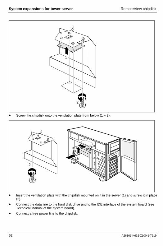
RemoteView chipdiskA chipdisk with installed RemoteView software is available as an option for using RemoteView onthe server. The RemoteView chipdisk is equipped with an IDE interface and is installed in the servermounted on the ventilation plate.
Installing a RemoteView chipdiskÊ Remove the left-hand side cover (see "Opening the server").
1
1
2
2b2a
2c
Ê Unscrew the ventilation plate (1) and remove it (2).
System expansions for tower server RemoteView chipdisk
52 A26361-K632-Z100-1-7619
1
2
Ê Screw the chipdisk onto the ventilation plate from below (1 + 2).
1
21a
2
1b 1c
Ê Insert the ventilation plate with the chipdisk mounted on it in the server (1) and screw it in place(2).
Ê Connect the data line to the hard disk drive and to the IDE interface of the system board (seeTechnical Manual of the system board).
Ê Connect a free power line to the chipdisk.

RemoteView chipdisk System expansions for tower server
A26361-K632-Z100-1-7619 53
Ê Replace the left-hand side cover (see "Assembling the server").
So that the RemoteView chipdisk can be started automatically later, enter the chipdisk parametersin the BIOS Setup and boot once from the chipdisk with it. Proceed as follows:
Ê Start the server and invoke BIOS Setup.
Ê Enter the chipdisk parameters underHard Disk 1. Instructions are provided in the TechnicalManual for the system board or in the "BIOS Setup" manual.
Ê Save the setting and terminate BIOS Setup.The server boots MS-DOS and RemoteView from the chipdisk.
iIf the RemoteView software is not yet installed on the chipdisk, install the software asdescribed in the manual for RemoteView
Ê To terminate RemoteView, use the menu item Boot Original OS.
The server boots the standard operating system. How to operate RemoteView is described in thecorresponding documentation of RemoteView.
Removing a RemoteView chipdiskÊ Remove the left-hand side cover (see "Opening the server").
Ê Disconnect the cables from the chipdisk.
1
1
2
2b2a
2c
Ê Remove the screw (1) and take out the ventilation plate with the chipdisk mounted on it (2).

System expansions for tower server RemoteView chipdisk
54 A26361-K632-Z100-1-7619
1
2
Ê Unscrew the chipdisk from the ventilation plate (1).
1
21a
2
1b 1c
Ê Insert the ventilation plate in the server again (1) and screw it into place (2).
Ê Replace the left-hand side cover (see "Assembling the server").

Accessible drives System expansions for tower server
A26361-K632-Z100-1-7619 55
Accessible drivesThe server accommodates four accessible drives (three 5 ¼-inch drives and one 3 ½-inch drive). A5 ¼-inch drive with a full installation height occupies two 5 ¼-inch half-height bays.
For error-free operation of SCSI hard drives it is important that each drive on the SCSI bus isassigned a unique SCSI-ID (0 - 6) and that the matching resistor (terminator) is only connected andenabled on the drive at the end of the SCSI cable.
As the CD-ROM drive fitted by default is connected at the end of the SCSI cable, the termination isenabled.
Ê Please read the drive documentation.
Ê Assign an as yet unassigned SCSI-ID to the new drive and disable the terminating resistor.
Installing an accessible 5 ¼-inch driveÊ Remove the control panel trim plate, the left-hand side cover and, it you wish to install an
accessible drive in the upper or middle bay, also the right-hand side cover (see "Opening theserver").
2
1
2
1
Ê If you install a half-height drive, then remove the EMC insert from the desired bay (1) and theplastic insert from the control panel trim plate (2).
Ê If you install a DLT drive, then remove the two EMC inserts (1) and two plastic inserts from thecontrol panel trim plate (2).

System expansions for tower server Accessible drives
56 A26361-K632-Z100-1-7619
2
2 1
1
a 2
CD ROM DLT Auto Loader
1
2
The illustration shows the possible mounting points on the drive cage for the three drive types CD-ROM, DLT and Auto-Loader. For reasons of clarity, the drive cage is shown here schematically fromthe side. The respective mounting points are shown as filled-in circles or ovals.
Ê If you install a half-height drive, then push it into the bay (1) and secure it on both sides withtwo screws each (2).
Ê If you install a DLT drive, then place it on the carrier plate provided (a), push it with the plateinto the center and upper bay (1) and secure it on both sides with two screws each (2).
iThe accessible 5 ¼-inch drive in the bottom bay is only secured on the left-hand side withtwo knurled screws.
Ê Connect the cables to the drive.
Ê Close the server again (see "Assembling the server").

Accessible drives System expansions for tower server
A26361-K632-Z100-1-7619 57
Removing an accessible 5 ¼-inch driveÊ Remove the control panel trim plate, the left-hand side cover and, if you wish to install an
accessible drive in the upper or center bay, also the right-hand side cover (see "Opening theserver").
Ê Pull the cables from the drive.
1
2
1
1
2
Ê Remove the four screws (1) and withdraw the drive from the bay (2).
21
Ê Place an EMC insert in the empty bay (1) and a plastic cover in the control panel trim plate (2).
Ê Close the server (see "Assembling the server").

System expansions for tower server Boards
58 A26361-K632-Z100-1-7619
Changing the floppy disk driveÊ Remove the left-hand side cover and the control panel trim plate (see "Opening the server").
Ê Disconnect the cables from the floppy disk drive.
1
2
1
2
Ê Remove the four knurled screws (1) and withdraw the floppy disk drive from the drive carrier(2).
1
2
Ê Push the new floppy disk drive into the bay (1) and secure it with the screws (2) you removedearlier.
Ê Connect the cables to the floppy disk drive again.
Ê Remount the control panel trim plate and the left-hand side cover (see "Assembling theserver").
BoardsBefore installing or removing a board, please read the documentation supplied with the board.
Boards System expansions for tower server
A26361-K632-Z100-1-7619 59
Installing a boardÊ Remove the left-hand side cover (see "Opening the server").
1
2
1
2
1
2
3
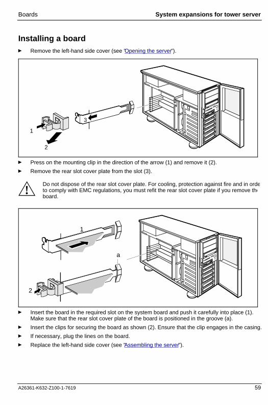
Ê Press on the mounting clip in the direction of the arrow (1) and remove it (2).
Ê Remove the rear slot cover plate from the slot (3).
!Do not dispose of the rear slot cover plate. For cooling, protection against fire and in ordeto comply with EMC regulations, you must refit the rear slot cover plate if you remove theboard.
2
a
1
2
1
Ê Insert the board in the required slot on the system board and push it carefully into place (1).Make sure that the rear slot cover plate of the board is positioned in the groove (a).
Ê Insert the clips for securing the board as shown (2). Ensure that the clip engages in the casing.
Ê If necessary, plug the lines on the board.
Ê Replace the left-hand side cover (see "Assembling the server").

System expansions for tower server Power supply module
60 A26361-K632-Z100-1-7619
Removing a boardÊ Remove the left-hand side cover (see "Opening the server").
Ê Remove the lines connected to the board.
1
21
2
3
Ê Press on the clip in the direction of the arrow (1) and remove it (2).
Ê Pull the board out of the slot (3).
1
2
1
2
2a
1
Ê Insert the rear slot cover plate into the empty slot (1). Make sure that the rear slot cover plate ispositioned in the groove (a).
Ê Insert the clips for securing the rear slot cover plate as shown (2). Ensure that the clip engagesin the casing.
Ê Replace the left-hand side cover (see "Assembling the server").
Power supply moduleThe servers with a modular hot-plug power supply can be equipped with one or two power supplymodules. With two power supply modules the servers are equipped with a redundant power supply.If one module fails, the respective other module ensures unimpaired further operation. The defectivemodule can be replaced during operation.

Power supply module System expansions for tower server
A26361-K632-Z100-1-7619 61
There are two types of hot-plug-capable power supply modules, which are easy to distinguish on theconnection side (see following illustration). Both versions automatically adjust to the proper voltagerange.
!A server may only be equipped with one type of power supply module. Mixed equippingwill cause the modules to be destroyed
Installing the power supply module
1
23
1
3
2
Ê Unscrew the screws on the lock of the blind insert (1), slide the latch upward somewhat (2),and take out the blind insert (3).

System expansions for tower server Power supply module
62 A26361-K632-Z100-1-7619
1
1
4
3
2
1
1
2
3
4
Ê Slide the latch on the power supply module upward somewhat (1) and insert the power supplymodule in the installation bay (2).
Ê Lock the power supply module in place with the latch in the casing (3) and screw the latch inplace in this position (4).

Power supply module System expansions for tower server
A26361-K632-Z100-1-7619 63
Removing the power supply module
3
3
1
2
1
2
Ê Unscrew the screw on the lock of the power supply module (1), slide the latch upwardsomewhat (2) and pull the power supply module out of the installation bay (3).

System expansions for tower server Power supply module
64 A26361-K632-Z100-1-7619
3
1
2
1
3
2
Ê Slide the locking slide on the blind insert upward somewhat and insert the blind insert in theinstallation bay (1).
Ê Secure the blind insert with the locking slide in the housing (2) and screw it in place in thisposition (3).

Exchanging the fan System expansions for tower server
A26361-K632-Z100-1-7619 65
Exchanging the fanThe two server fans can easily be replaced during servicing.
Ê Remove the left-hand side cover (see "Opening the server").
1
1
2
1
2
2
3
4
Ê Pull the connecting cable off the fan (1), press on the retaining clips (2) and take out the fan tothe side (3 + 4).
1
1
2
1
2
2
3
Ê Place the new fan in the bay (1). When doing so, make sure the fan retaining clips engageproperly (2).
Ê Connect the cable to the fan (3).
Ê Replace the left-hand side cover (see "Assembling the server").

System expansions for tower server Extensions on the system board
66 A26361-K632-Z100-1-7619
Extensions on the system boardDetails of how you upgrade the main memory of the server, replace the lithium battery or processoror make certain settings are provided in the Technical Manual of the system board.
Ê Remove the left-hand side cover (see "Opening the server").
Ê Remove the ventilation plate (see "RemoteView chipdisk").
Ê Make the desired expansions or settings (see the Technical Manual for the system board).
Ê Install the ventilation plate again (see "RemoteView chipdisk").
Ê Replace the left-hand side cover (see "Assembling the server").

A26361-K632-Z100-1-7619 67
System expansions for rack serverBecause the internal design of tower servers and rack servers is identical, this chapter only coversthe activities which differ from those for the tower server. These include opening and closing theserver and the installation and removal of accessible drives. On the other hand, please read thecorresponding chapters in "System expansions for tower server" when you wish to carry out thefollowing work:
• Installing and removing SCSI hard disk drives• Installing/removing a RemoteView hard disk drive• Installing and removing boards• Exchanging the fan• Installing extensions on the system board• Installing and removing the power supply module
iYou will find an overview and a brief description of the installed system boards in theserver lid.A detailed description of the system board is provided in the corresponding TechnicaManual.
Opening the server
!Please take note of the safety information in the chapter "Important notes".
Ê Switch the server off.
!Pull all power plugs out of the power outlets
Ê If the SCSI cables of the server are routed in a limited cable guide, then remove the SCSIcables from the rack cable guides (see "Mounting cable guides and routing cables" in thesection "Installing the rack server").

System expansions for rack server Opening the server
68 A26361-K632-Z100-1-7619
1
2
Ê Release the four knurled screws (1) and withdraw the server from the rack as far as it will go(2). The slide stops of the extending rails left and right must engage.
1
2
Ê Remove the knurled screw behind the front panel (1) and push the cover forward as far aspossible (2).
1
2
Ê Lift the cover on the right-hand side (1) and remove it (2).

Assembling the server System expansions for rack server
A26361-K632-Z100-1-7619 69
If you wish to install or remove accessible drives, then also remove the control panel trim plate.
1
2
11
3
Ê Press the two retaining clips of the control panel trim plate behind the front panel firmlydownward (1), fold out the control panel trim plate (2) and remove it (3).
Assembling the serverIf you have inserted or removed an accessible drive, you must refit the control panel trim plate.
1 2
Ê If you have installed an accessible drive, then remove the corresponding plastic trim plate fromthe control panel trim plate (1).
Ê If you have removed an accessible drive, then remount the corresponding plastic trim plate inthe control panel trim plate (2).

System expansions for rack server Assembling the server
70 A26361-K632-Z100-1-7619
1
2
Ê Mount the control panel trim plate as shown (1 + 2). Make sure that the retaining clips of thecontrol panel trim plate engage in the front panel.
3
1
2
Ê Insert the cover in the casing on the left-hand side (1), slide it forward as far as possible (2) andfold it onto the casing at the right (3).
1
2
Ê Slide the cover back as far as possible (1) and screw it in place with the knurled screw behindthe front panel (2).

Assembling the server System expansions for rack server
A26361-K632-Z100-1-7619 71
21
Ê Press the locking spring (1) on both sides and push the server back into the rack (2).
1
Ê Secure the server in the rack (1) using the four knurled screws.
Ê If the cables of the server are laid in a limited cable guide, place the SCSI cables back in thecable guides (see "Mounting cable guides and routing cables" section "Installing the rackserver").
Ê Plug in the power plug again.

System expansions for rack server Accessible drives
72 A26361-K632-Z100-1-7619
Accessible drivesThe server accommodates four accessible drives (three 5 ¼-inch drives and one 3 ½-inch drive). A5 ¼-inch drive with a full installation height occupies two 5 ¼-inch half-height bays.
For error-free operation of SCSI hard drives it is important that each drive on the SCSI bus isassigned a unique SCSI-ID (0 - 6) and that the matching resistor (terminator) is only connected andenabled on the drive at the end of the SCSI cable.
As the CD-ROM drive fitted by default is connected at the end of the SCSI cable, the termination isenabled.
Ê Read the documentation supplied with the drive and make the required settings (SCSI ID,termination) at the drive.
Installing an accessible 5 ¼-inch driveÊ Open the server (see "Opening the server").
Ê Pull the cables from the installed accessible drives.
1
2
Ê Remove the four screws (1) and pull out the drive cage (2).

Accessible drives System expansions for rack server
A26361-K632-Z100-1-7619 73
3
1
6
46
3
5
CD ROM DLT Auto Loader
2
4
1
The illustration shows the possible mounting points on the drive cage for the three drive types CD-ROM, DLT and Auto-Loader. For reasons of clarity, the drive cage is shown here schematically fromthe side. The respective mounting points are shown as filled-in circles or ovals.
Ê If you install a half-height drive, then remove the EMC cover from the corresponding bay (1),insert the drive in this bay (2) and secure it on both sides of the drive cage with two screws (3).
Ê If you install a DLT drive, then remove the EMC covers from the two upper bays (1), insert thedrive on the carrier plate provided (4), insert it in the drive cage with the plate (5) and secure iton both sides of the drive cage with two screws (6).

System expansions for rack server Accessible drives
74 A26361-K632-Z100-1-7619
2
1
Ê Insert the drive cage into the server (1) and fasten it using the screws you removed earlier (2).
Ê Connect the cables to the drives.
Ê Close the server (see "Assembling the server").
Removing an accessible 5 ¼-inch driveÊ Open the server (see "Opening the server").
Ê Pull the cables from the drives.
1
2
Ê Remove the four screws (1) and withdraw the drive cage (2).

Accessible drives System expansions for rack server
A26361-K632-Z100-1-7619 75
1
1
23
Ê Remove the four screws (1) and withdraw the drive from the drive cage (2).
Ê Insert an EMC cover (3).
2
1
Ê Insert the drive cage into the server (1) and fasten it using the screws you removed earlier (2).
Ê Connect the cables to the remaining floppy disk drive.
Ê Close the server (see "Assembling the server").

System expansions for rack server Accessible drives
76 A26361-K632-Z100-1-7619
Changing the floppy disk driveÊ Open the server (see "Opening the server").
Ê Disconnect the cables from the floppy disk drive.
1
2
Ê Remove the two screws (1) and withdraw the floppy disk drive from the bay (2).
2
1
Ê Push the new floppy disk drive into the bay (1) and secure it with the two screws (2).
Ê Connect the cables to the floppy disk drive again.
Ê Close the server (see "Assembling the server").

A26361-K632-Z100-1-7619 77
Technical dataElectrical data
Rated voltage range: 100 V - 125 V / 200 V - 240 V
Frequency: 50 Hz - 60 Hz
Rated current in basic configuration:
• Server without monitor outlet or monitoroutlet is not used
100 V - 125 V / 1,8 A200 V - 240 V 1,0 A
Max. rated current:
• Server without monitor outlet or monitoroutlet is not used
• Server with monitor socket
• Monitor socket
100 V - 125 V / 6,0 A200 V - 240 V 3,5 A
100 V - 125 V / 9,0 A200 V - 240 V 5,0 A
100 V - 125 V / 3.0 A200 V - 240 V 1,5 A
Protection class: I
Regulations complied with: EN 60950 / VDE 0805UL 1950CSA 22.2 No 950
Dimensions of tower server (including door and feet)
Width:Depth:Height:Weight:
288 mm685 mm480 mmapprox. 18 - 35 kg
Dimensions of rack server (including rails and installed in rack)
Width:Depth:Height:Weight:
483 mm754 mm266 mmapprox. 18 - 35 kg
Environmental conditions
Environment class 3K2Environment class 2K2
DIN IEC 721 part 3-3DIN IEC 721 part 3-2
Temperature:• Operating (3K2)• Transport (2K2)
15 °C .... 35 °C-25 °C .... 60 °C
Condensation in operating must be avoided.
Noise level
Sound power level LWAd (ISO 9296): ≤ 5.8 dB
Sound pressure levelat bystander position LpAm (ISO 9296):
≤ 43 dB


A26361-K632-Z100-1-7619 79
Index
55 1/4-inch drive
installing 55, 72removing 57, 74
AAccessible drive 55, 72
installing 55, 72removing 57, 74
ASR&R 2
BBattery, replacing 66BIOS Setup
preventing calling 37write protection 37
BIOS Update 2BIOS, protecting boards with own BIOS 37Blank insert
inserting 50removing 49
Board 58installing 59removing 60safety 6
CCable
connecting 11disconnecting 11
Cable laying, limited 23Cable routing
unlimited 21with cable chain 21
CD-ROM driveindicator 31installing 55, 72removing 57, 74
CE certificate 6Chipcard reader
indicator 31Chipdisk 51
installing 51removing 53
Class A Compliance Statement 7Cleaning
keyboard 35monitor 35

Index
80 A26361-K632-Z100-1-7619
server 35Closing
server 46, 69Configuration
server 33Connecting, server 13Control panel trim plate
mounting 46removing 45
Controls 29Courier 3
DDAC
defective drive 42DAC960 33DACCF 33Data
electrical 77technical 77
Data protection 37Data, environmental 77Date, not correct 41Defective drive 42Devices
connecting 13, 24interface 13
Dimensions 77Disk Array Controller 1, 48Display, cleaning 35Disposal and recycling 10DLT drive, installing 55, 72Door
mounting 46removing 45
Drivechanging floppy disk drive 58, 76defective 42indicator 31installing accessible 5 1/4-inch drive 55, 72installing SCSI hard disk drive 48removing accessible 5 1/4-inch drive 57, 74removing SCSI hard disk drive 48reported as dead 42
Drive error, indicator 31Drive LEDs 31
EEDC 2Electrical data 77Electromagnetic compatibility 6EMC 6Environmental class 77Environmental conditions 77

Index
A26361-K632-Z100-1-7619 81
Environmental data 77Error
drive defect 42drive reported as dead 42flickering screen 40floppy disk cannot be read/written 41message on the screen 42no mouse pointer 41screen 39screen display drifts 40server 39server switches itself off 39system does not boot 41time 41wrong date 41
ESD 6Extending unit 18Extensions, system board 66External devices
connecting 13ports 13
FFan, exchanging 65FCC statement 7Features 1Flickering stripes on the monitor screen 40Floppy disk drive
changing 58, 76indicator 31write-protection 37
Floppy disk, cannot be read or written 41Further information 1
GGeneral information 1Guarantee coupon booklet 11
HHard disk drive
indicator 31installing 48removing 48
Hard disk subsystem 1Height module 17Hot replace 1, 48Hot-plug power supply 16, 26Housing side cover, mounting 47
IICU 33IDE interface 51Important notes 5Indicator, remains blank 39

Index
82 A26361-K632-Z100-1-7619
Indicators 29CD-ROM drive 31chipcard reader active 31drive active 31drive error 31floppy disk drive active 31hard disk drive active 31power-on indicator 31power-on indicator fails to light 39
Information, general 1Installation 11Installing
5 1/4-inch drive 55, 72board 59fan 65power supply module 61rack server 17RemoteView chipdisk 51tower server 12
Interfaces 13, 24ISA configuration 33Italics 3
KKeyboard
cleaning 35connecting 12keyboard port 13
LLED 29Limited cable routing 23Line voltage range 25Lithium battery, changing 66Locking, server 34
MMain memory, upgrading 66Main switch 31Memory scrubbing 2Message, error 42Modular power supply 16, 26Monitor
connecting to power voltage 14drifting display 40error message 42monitor port 13
Mounting assembly kit, rack server 17Mouse
cleaning 35no mouse pointer 41PS/2 port 13
Mouse pointer, not dislayed 41

Index
A26361-K632-Z100-1-7619 83
NNoise level 77Notational conventions 3Note, power cord selection 8Notes
CE certificate 6disposal and recycling 10safety 5
Novell Netware 3.12 33
OON/OFF switch 31Onboard SCSI controller
configuring 33Opening, server 43, 67Operating system
not starting 41preventing start 37
Overviewports and slots 24server 1
PPacking material 11Parallel port 13PDA technology 2Ports 13, 24Power cord selection 8Power supply
hot-plug 26modular 16, 26redundant 25standard 14, 25
Power supply module 60installing 61removing 63
Power voltage, connecting to 14, 25Power-on
preventing 37Power-on indicator 31
doesn't fail to light 39Processor, upgrading 66Property protection 37Protection, theft 37PS/2 keyboard port 13PS/2 mouse port 13
RRack Architect 17Rack server
connecting 24connectors 24extending unit 18inserting 17

Index
84 A26361-K632-Z100-1-7619
installation steps 17installing 17mounting assembly kit 17system expansions 67
RAID level 2, 48Ready-to-operate 32Recycling 10Redundant power supply 14, 25Remote power-on, preventing 37Remote Test and Diagnosis System 51RemoteView chipdisk 51
installing 51removing 53
Removing5 1/4-inch accessible drive 57board 60fan 65Power supply module 63RemoteView chipdisk 53SCSI hard disk drive 50
RTDS 2
SSafety 5
board 6SCA interface 1, 48SCO UNIX 33Screen
flickering 40SCSI hard disk drive
installing 48, 49removing: 48, 50
SCSI ID, accessible drives 55, 72SCU 33Security function, BIOS Setup 37Security measures 37Security standards 77Select, power cord 8Serial port 13Server
opening 43switches itself off 39
Server management 2ServerStart 2, 33ServerView 2Service compartment, tower server 35Side cover
removing 44Standard power supply 14, 25Stand-by 32Summer time 41Surface 77Switch 29Switch off by program
prevent 37

Index
A26361-K632-Z100-1-7619 85
Switching off, server 31Switching on, server 31Symbols, explanation of 3System board 1
extensions 66System LEDs 31System startup, preventing 37Systemexpansions
rack server 67tower server 43
TTechnical data 77Temperature 77Terminating resistor, accessible drive 55, 72Termination 55, 72Time, not correct 41Tower server
installing 12locking 34service compartment 35system expansions 43unlocking 27
Transport 10Trouble
drive defect 42drive reported as dead 42flickering screen 40floppy disk cannot be read/written 41message on the screen 42no mouse pointer 41screen 39screen display drifts 40server 39server switches itself off 39system does not boot 41
Troubleshooting and tips 39
UUltra-Wide-SCSI controller 48Unlimited cable routing 21Unlocking, tower server 27
WWeight 77Winter time 41Write protection
BIOS Setup 37floppy disk drive 37
Wrong date 41Wrong time 41

Information on this document On April 1, 2009, Fujitsu became the sole owner of Fujitsu Siemens Compu-ters. This new subsidiary of Fujitsu has been renamed Fujitsu Technology So-lutions.
This document from the document archive refers to a product version which was released a considerable time ago or which is no longer marketed.
Please note that all company references and copyrights in this document have been legally transferred to Fujitsu Technology Solutions.
Contact and support addresses will now be offered by Fujitsu Technology So-lutions and have the format …@ts.fujitsu.com.
The Internet pages of Fujitsu Technology Solutions are available at http://ts.fujitsu.com/... and the user documentation at http://manuals.ts.fujitsu.com.
Copyright Fujitsu Technology Solutions, 2009
Hinweise zum vorliegenden Dokument Zum 1. April 2009 ist Fujitsu Siemens Computers in den alleinigen Besitz von Fujitsu übergegangen. Diese neue Tochtergesellschaft von Fujitsu trägt seit-dem den Namen Fujitsu Technology Solutions.
Das vorliegende Dokument aus dem Dokumentenarchiv bezieht sich auf eine bereits vor längerer Zeit freigegebene oder nicht mehr im Vertrieb befindliche Produktversion.
Bitte beachten Sie, dass alle Firmenbezüge und Copyrights im vorliegenden Dokument rechtlich auf Fujitsu Technology Solutions übergegangen sind.
Kontakt- und Supportadressen werden nun von Fujitsu Technology Solutions angeboten und haben die Form …@ts.fujitsu.com.
Die Internetseiten von Fujitsu Technology Solutions finden Sie unter http://de.ts.fujitsu.com/..., und unter http://manuals.ts.fujitsu.com finden Sie die Benutzerdokumentation.
Copyright Fujitsu Technology Solutions, 2009