hard disk drive specification ultrastar 15k147 - hgst · hard disk drive specification ultrastar...
TRANSCRIPT
Hitachi Ultrastar 15K147 (FC-AL) Hard Disk Drive Specification
Hard Disk Drive Specification
Ultrastar 15K1473.5 inch 4G FC-AL Hard Disk Drive
Models: HUS151414VLF400HUS151473VLF400HUS151436VLF400
Version 1.4 01 November 2006
Warning: Printed copies of this document are considered current only on the date of print. Replacement and disposal of down-level versions is the responsibility of the document holder.

Hitachi Ultrastar 15K147 (FC-AL) Hard Disk Drive Specification
Hitachi Ultrastar 15K147 (FC-AL) Hard Disk Drive Specification
Hard Disk Drive Specification
Ultrastar 15K1473.5 inch 4G FC-AL Hard Disk Drive
Models: HUS151414VLF400HUS151473VLF400HUS151436VLF400
Version 1.4 01 November 2006
Warning: Printed copies of this document are considered current only on the date of print. Replacement and disposal of down-level versions is the responsibility of the document holder.
Hitachi Ultrastar 15K147 (FC-AL) Hard Disk Drive Specification
1st Edition (Rev. 0.1) (20 July 2004) DRAFT2md Edition (Rev. 0.2) (4 February 2005) DRAFT 3rd Edition (Rev. 0.3) (01 April 2005) DRAFT4th Edition (Rev. 0.4) (16 May 2005) DRAFT5th Edition (Rev. 1.0) (06 June 2005) Revised6th Edition (Rev. 1.1)(25 August 2005) Revised7th Edition (Rev 1.2)(16 September 2005) Revised8th Edition (Rev 1.3)(07 March 2006) Revised9th Edition (Rev. 1.4)(01 November 2006) Final
The following paragraph does not apply to the United Kingdom or any country where such provisions are inconsistent with local law: HITACHI GLOBAL STORAGE TECHNOLOGIES PROVIDES THIS PUBLICATION "AS IS" WITHOUT WARRANTY OF ANY KIND, EITHER EXPRESS OR IMPLIED, INCLUDING, BUT NOT LIMITED TO, THE IMPLIED WARRANTIES OF MERCHANTABILITY OR FITNESS FOR A PARTICULAR PURPOSE. Some states do not allow disclaimer or express or implied warranties in certain transactions, therefore, this statement may not apply to you.This publication could include technical inaccuracies or typographical errors. Changes are periodically made to the informa-tion herein; these changes will be incorporated in new editions of the publication. Hitachi may make improvements or changes in any products or programs described in this publication at any time.
It is possible that this publication may contain reference to, or information about, Hitachi products (machines and programs), programming, or services that are not announced in your country. Such references or information must not be construed to mean that Hitachi intends to announce such Hitachi products, programming, or services in your country.
Technical information about this product is available by contacting your local Hitachi Global Storage Technologies representa-tive or on the Internet at http://www.hgst.com
Hitachi Global Storage Technologies may have patents or pending patent applications covering subject matter in this docu-ment. The furnishing of this document does not give you any license to these patents.
©Copyright Hitachi Global Storage Technologies
Note to U.S. Government Users —Documentation related to restricted rights —Use, duplication or disclosure is subject to restrictions set forth in GSA ADP Schedule Contract with Hitachi Global Storage Technologies.
Hitachi Ultrastar 15K147 (FC-AL) Hard Disk Drive Specification
Table of Contents
1.0 General....................................................................................................11.1 Introduction........................................................................................11.2 Glossary .............................................................................................11.3 Caution...............................................................................................1
2.0 Outline of the Drive ...............................................................................33.0 Fixed-disk Subsystem Description .......................................................5
3.1 Control Electronics ............................................................................53.2 Head Disk Assembly .........................................................................53.3 Actuator .............................................................................................5
4.0 Drive Characteristics .............................................................................74.1 Formatted Capacity............................................................................74.2 Data Sheet ..........................................................................................74.3 Inquiry Information............................................................................8
4.3.1 Product ID.................................................................................84.3.2 World Wide ID - Block Assignment ........................................8
4.4 Cylinder allocation.............................................................................94.5 Performance characteristics ...............................................................10
4.5.1 Mechanical positioning.............................................................114.5.2 Drive ready time .......................................................................134.5.3 Spindle stop time ......................................................................134.5.4 Data transfer speed....................................................................134.5.5 Buffering operation (read ahead/write cache)...........................144.5.6 Throughput................................................................................14
5.0 Data Integrity .........................................................................................175.1 Equipment Status ...............................................................................175.2 Error Recovery Procedure..................................................................17
6.0 Physical Format .....................................................................................196.1 Shipped Format (P-List) ....................................................................196.2 Reassigned Format (G-List)...............................................................19
7.0 Electrical Interface.................................................................................217.1 FC-AL Connector ..............................................................................21
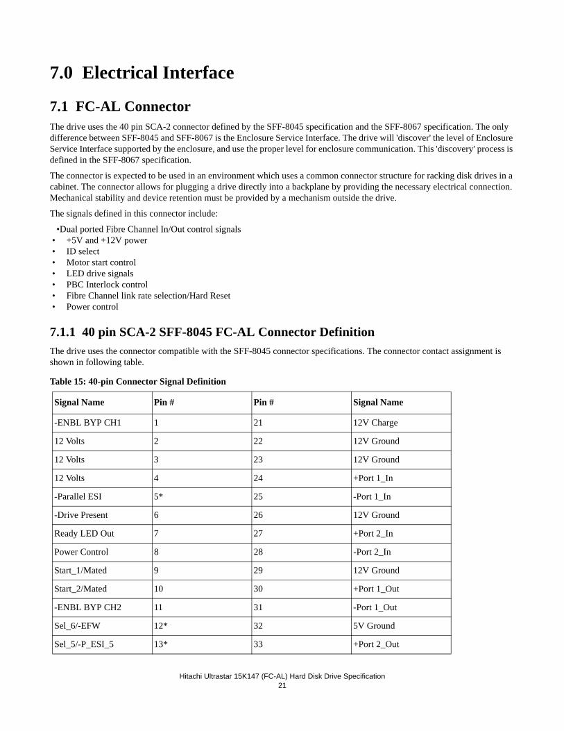
7.1.1 40 pin SCA-2 SFF-8045 FC-AL Connector Definition............217.1.2 Voltage and Ground Signals .....................................................227.1.3 Fault LED Out ..........................................................................227.1.4 Ready LED Out ........................................................................227.1.5 Start Mated Controls .................................................................237.1.6 SEL_n and Enclosure Service Signals......................................237.1.7 –ENBL_BYP CH1, -ENBL_BYP_CH2..................................257.1.8 –Drive Present..........................................................................257.1.9 Dev_Ctrl_Code_x .....................................................................25
8.0 Environment...........................................................................................278.1 Temperature and humidity.................................................................27
Hitachi Ultrastar 15K147 (FC-AL) Hard Disk Drive Specification
8.2 Storage requirements .........................................................................288.2.1 Packaging..................................................................................288.2.2 Storage time ..............................................................................28
8.3 Corrosion test .....................................................................................288.4 Cooling requirements.........................................................................29
9.0 DC Power Requirements.......................................................................319.1 Power Supply Current, Average and Peak.........................................329.2 Ripple Voltage ...................................................................................339.3 Power Consumption Efficiency Index...............................................33
10.0 Reliability..............................................................................................3510.1 Start/Stop Cycles..............................................................................3510.2 Data Reliability ................................................................................3510.3 Seek errors .......................................................................................3510.4 Failure prediction (PFA/S.M.A.R.T) ...............................................3510.5 Preventive Maintenance...................................................................3510.6 Temperature Warning ......................................................................35
11.0 Mechanical Specifications ...................................................................3711.1 Outline .............................................................................................3711.2 Mechanical Dimensions...................................................................3711.3 Interface Connector..........................................................................3911.4 Mounting Positions and Tappings ...................................................4011.5 Drive Mounting................................................................................4111.6 Heads Unload and Actuator Lock....................................................4111.7 Breather Hole ...................................................................................41
12.0 Vibration and Shock............................................................................4312.1 Operating Vibration .........................................................................43
12.1.1 Random Vibration...................................................................4312.1.2 Swept Sine Vibration .............................................................43
12.2 Non-operating Vibrations ................................................................4312.2.1 Random Vibration..................................................................4312.2.2 Swept Sine Vibration .............................................................43
12.3 Operating shock ..............................................................................4312.4 Non-operating shock.......................................................................44
12.4.1 Half sinewave shock pulse......................................................4412.4.2 Rotational shock ....................................................................44
13.0 Acoustics ...............................................................................................4513.1 Sound power levels ..........................................................................45
14.0 Identification ........................................................................................4714.1 Labels...............................................................................................47
15.0 Electromagnetic Compatibility...........................................................4916.0 Standards ..............................................................................................51
16.1 UL and C-UL Standard Conformity ................................................5116.2 European Standards Compliance .....................................................5116.3 German Safety Mark........................................................................5116.4 Flammability ....................................................................................5116.5 Corporate Standards Compliance ....................................................51
Hitachi Ultrastar 15K147 (FC-AL) Hard Disk Drive Specification
17.0 FC-AL attachment ...............................................................................5317.1 Fundamentals ...................................................................................53
17.1.1 Node and Port names ..............................................................5417.1.2 NL_Port address .....................................................................5417.1.3 Primitive signals and sequences .............................................5517.1.4 Frames....................................................................................5617.1.5 Sequences................................................................................5617.1.6 Exchanges ...............................................................................57
17.2 Basic Link Services .........................................................................5717.2.1 Abort sequence (ABTS).........................................................5717.2.2 Basic accept (BA_ACC) .........................................................5817.2.3 Basic reject (BA_RJT)............................................................59
17.3 Extended Link Services ...................................................................6017.3.1 Link Service Accept (LS_ACC) ............................................6117.3.2 Link Service Reject (LS_RJT)...............................................6217.3.3 Port Login (PLOGI)...............................................................6317.3.4 Logout (LOGO) .....................................................................7117.3.5 Fabric Login (FLOGI) ...........................................................7217.3.6 Fabric Address Notification (FAN) .......................................7617.3.7 Port Discovery (PDISC) ........................................................7717.3.8 Address Discovery (ADISC) .................................................7717.3.9 Process Login (PRLI) ............................................................7817.3.10 Process Logout (PRLO).......................................................8217.3.11 Read Link Error Status Block (RLS)...................................8417.3.12 Report Node Capabilities (RNC).........................................8617.3.13 Re-instate Recovery Qualifiers (RRQ) ................................9017.3.14 Third Party Process Logout (TPRLO) .................................9117.3.15 Request Node Identification Data (RNID) ...........................93
17.4 Common Fibre Channel Services ....................................................9717.4.1 Register FC-4 Types (RFT_ID) ..............................................99
17.5 FC-AL timers ...................................................................................10117.5.1 Link Failure.............................................................................102
17.6 Invalid frame delimiter ....................................................................10218.0 SCSI-FCP .............................................................................................103
18.1 Terminology.....................................................................................10318.2 Information Units.............................................................................104
18.2.1 FCP_CMND ...........................................................................10518.2.2 FCP_XFER_RDY...................................................................10718.2.3 FCP_DATA ............................................................................10718.2.4 FCP_RSP ................................................................................107
18.3 Task Attributes.................................................................................10918.4 Task Management functions ............................................................110
18.4.1 Abort Task (Implemented as ABTS BLS).............................11118.4.2 Abort Task Set ........................................................................11118.4.3 Terminate Task .......................................................................11218.4.4 Clear ACA ..............................................................................112
Hitachi Ultrastar 15K147 (FC-AL) Hard Disk Drive Specification
18.4.5 Target Reset ............................................................................11218.4.6 Clear Task Set .........................................................................11218.4.7 Reset LUN ..............................................................................112
18.5 Miscellaneous ..................................................................................11218.5.1 Tags.........................................................................................11218.5.2 Auto-Contingent Allegiance (ACA).......................................11218.5.3 Autosense...............................................................................113
19.0 SCSI Command Set ............................................................................11519.1 SCSI Control Byte ...........................................................................11719.2 Abbreviations...................................................................................11719.3 Byte ordering conventions ...............................................................11719.4 FORMAT UNIT (04).......................................................................118
19.4.1 Defect list ................................................................................12019.4.2 Defect Descriptor ....................................................................121
19.5 INQUIRY (12) .................................................................................12419.5.1 Inquiry Data ............................................................................125
19.6 LOG SELECT (4C) .........................................................................13619.7 LOG SENSE (4D) ...........................................................................139
19.7.1 Log Page parameters...............................................................14019.7.2 Log Sense Page 0 ....................................................................14119.7.3 Log Sense Page 2 ....................................................................14219.7.4 Log Sense Page 3 ....................................................................14419.7.5 Log Sense Page 5 ....................................................................14619.7.6 Log Sense Page 6 ....................................................................14819.7.7 Log Sense Page D ...................................................................14919.7.8 Log Sense Page E ...................................................................15019.7.9 Log Sense Page F....................................................................15119.7.10 Log Sense Page 10................................................................15219.7.11 Log Sense Page 15................................................................15519.7.12 Log Sense Page 2F................................................................15819.7.13 Log Sense Page 30................................................................15919.7.14 Log Sense Page 37................................................................162
19.8 MODE SELECT (15) ......................................................................16419.9 MODE SELECT (55) ......................................................................16519.10 MODE SENSE (1A) ......................................................................166
19.10.1 Mode Parameter List.............................................................16719.10.2 Mode Page 00 (Vendor Unique Parameters) ........................17119.10.3 Mode Page 01 (Read/Write Error Recovery Parameters).....17319.10.4 Mode Page 02 (Disconnect/Reconnect Parameters) .............17819.10.5 Mode Page 03 (Format Device Parameters) .........................17919.10.6 Mode Page 04 (Rigid Disk Drive Geometry Parameters) ....18119.10.7 Mode Page 07 (Verify Error Recovery Parameters).............18219.10.8 Mode Page 08 (Caching Parameters)....................................18319.10.9 Mode Page 0A (Control Mode Page Parameters).................18519.10.10 Mode Page 0C (Notch Parameters) ....................................18719.10.11 Mode Page 19h (Fibre Channel Port Control Page) ...........189
Hitachi Ultrastar 15K147 (FC-AL) Hard Disk Drive Specification
19.10.12 Mode Page 1A (Power Control) .........................................19119.10.13 Mode Page 1C (Informational Exceptions Control) ...........192
19.11 MODE SENSE (5A) ......................................................................19519.12 PERSISTENT RESERVE IN (5E) ................................................197
19.12.1 Service Action.......................................................................19719.12.2 Parameter data for Read Keys ..............................................19819.12.3 Parameter Data for Read Reservations .................................199
19.13 PERSISTENT RESERVE OUT (5F) ............................................20019.13.1 Service Action.......................................................................20119.13.2 Type ......................................................................................20119.13.3 Parameter list ........................................................................20219.13.4 Summary...............................................................................203
19.14 PRE-FETCH (34) ..........................................................................20519.15 READ (6) - (08) .............................................................................20619.16 READ (10) - (28) ...........................................................................20719.17 READ BUFFER (3C) ....................................................................208
19.17.1 Combined Header And Data (Mode 00000b).......................20919.17.2 Read Data (Mode 00010b)....................................................20919.17.3 Descriptor (Mode 00011b)....................................................21019.17.4 Read Data from Echo Buffer (Mode 01010b) ......................21119.17.5 Echo Buffer Descriptor (Mode 01011b) ...............................21119.17.6 Enable Expander Communications Protocol and Echo Buffer (Mode 11010b)211
19.18 READ CAPACITY (10) - (25) ......................................................21219.19 READ CAPACITY (16) (9E/10)...................................................21419.20 READ DEFECT DATA (37).........................................................215
19.20.1 Defect List Header ................................................................21719.20.2 Defect List Descriptor...........................................................21719.20.3 Bytes from Index Format (100b) ..........................................21819.20.4 Physical Sector Format (101b) .............................................218
19.21 READ DEFECT DATA (B7) ........................................................21919.21.1 Defect List Header ................................................................21919.21.2 Defect List Descriptor...........................................................22019.21.3 Bytes from Index Format (100b) ..........................................22019.21.4 Physical Sector Format (101b) .............................................220
19.22 READ LONG (3E) ........................................................................22119.23 REASSIGN BLOCKS (07) ...........................................................22219.24 RECEIVE DIAGNOSTICS RESULTS (1C) ................................224
19.24.1 Receive Diagnostic Results Page 0.......................................22519.24.2 Enclosure Service Information (ESI) Page Format ..............22619.24.3 Receive Diagnostic Results Page 40.....................................22719.24.4 Receive Diagnostic Page A0h...............................................229
19.25 RELEASE (17) ..............................................................................23019.26 RELEASE (57) ..............................................................................23119.27 REPORT DEVICE IDENTIFIER (A3/05)....................................23219.28 REPORT LUNS (A0) ....................................................................23419.29 REPORT SUPPORTED TASKS MANAAGEMENT FUNCTIONS (A3/0D)235
Hitachi Ultrastar 15K147 (FC-AL) Hard Disk Drive Specification
19.30 REPORT SUPPORTED OPERATION CODES (A3/0C) ............23619.30.1 All_commands parameter data format..................................23719.30.2 One_command parameter data format..................................238
19.31 REQUEST SENSE (03).................................................................23919.32 RESERVE (16) ..............................................................................24019.33 RESERVE (56) ..............................................................................24119.34 REZERO UNIT (01)......................................................................24219.35 SEEK (6) - (0B) .............................................................................24319.36 SEEK (10) - (2B) ...........................................................................24319.37 SEND DIAGNOSTIC (1D) ...........................................................244
19.37.1 Send Diagnostic Page 0 ........................................................24619.37.2 Send Diagnostic Page 40 ......................................................24619.37.3 Send Diagnostic Page A0h ...................................................247
19.38 SET DEVICE IDENTIFIER (A4/06) ............................................24819.39 START STOP UNIT (1B) .............................................................24919.40 SYNCHRONIZE CACHE (35) .....................................................25019.41 TEST UNIT READY (00) .............................................................25119.42 VERIFY (2F) .................................................................................25219.43 VERIFY (16) - (8F) .......................................................................25319.44 WRITE (6) - (0A) ..........................................................................25419.45 WRITE (10) - (2A) ........................................................................25519.46 WRITE AND VERIFY (10) - (2E)................................................25619.47 WRITE AND VERIFY (12) - (AE)...............................................25719.48 WRITE AND VERIFY (16) - (8E)................................................25819.49 WRITE BUFFER (3B) ..................................................................259
19.49.1 Combined Header And Data (Mode 00000b).......................25919.49.2 Write Data (Mode 00010b)...................................................26019.49.3 Download Microcode (Mode 00100b) .................................26119.49.4 Download Microcode and Save (Mode 00101b) -Single Binary File26119.49.5 Download Microprocessor Microcode and Save (Mode 00111b) - Multiple Binary Files
26119.49.6 Write Data to Echo Buffer (Mode 01010b) ..........................26219.49.7 Enable Expander Communications Protocol (Mode 11010b)262
19.50 WRITE LONG (3F).......................................................................26319.51 WRITE SAME (41) .......................................................................26419.52 WRITE SAME (16) - (93) .............................................................265
20.0 SCSI Status Byte ..................................................................................26721.0 Additional information........................................................................269
21.1 Obtaining an AL_PA .......................................................................26921.2 Loop Initialization Procedure ..........................................................26921.3 Flow Control ....................................................................................27121.4 Login Requirements.........................................................................27121.5 Public Loop Operation.....................................................................272
21.5.1 NL_Port Initialization .............................................................27321.6 SCSI Protocol ..................................................................................275
21.6.1 Priority of SCSI Status Byte Reporting ..................................275
Hitachi Ultrastar 15K147 (FC-AL) Hard Disk Drive Specification
21.6.2 Invalid LUN Processing..........................................................27521.6.3 Overlapped Commands...........................................................27521.6.4 Command Processing During Execution of Active I/O Process27621.6.5 Unit Attention Condition ........................................................27721.6.6 Command Processing During Startup and Format Operations27921.6.7 Internal Error Condition..........................................................27921.6.8 Deferred Error Condition........................................................27921.6.9 Degraded Mode.......................................................................28021.6.10 Command Processing while Reserved..................................287
21.7 Priority Commands ..........................................................................28721.8 Command Queuing ..........................................................................288
21.8.1 Queue Depth ...........................................................................28821.8.2 Queue Full Status....................................................................28821.8.3 Effects of LIP on Command Queuing ....................................28821.8.4 Termination of I/O Processes .................................................288
21.9 Command Reordering......................................................................28821.10 Concurrent I/O Process ..................................................................28821.11 Write Cache ...................................................................................28921.12 Automatic Rewrite/Reallocate .......................................................28921.13 Segmented Caching .......................................................................291
21.13.1 Overview...............................................................................29121.13.2 Read Ahead...........................................................................291
21.14 Multiple Initiator Systems .............................................................29121.14.1 Sense Data.............................................................................29121.14.2 Mode Pages...........................................................................291
21.15 Enclosure Services .........................................................................29121.15.1 Enclosure Initiated ESI .........................................................292
21.16 Multiple Initiator Environment ......................................................29221.16.1 Initiator Sense Data...............................................................29221.16.2 Initiator Mode Select/Mode Sense Parameters .....................292
21.17 Reset...............................................................................................29221.17.1 Reset Sources ........................................................................29321.17.2 Reset Actions ........................................................................293
21.18 Diagnostics.....................................................................................29321.18.1 Power on Diagnostics ...........................................................29321.18.2 Self-test via SEND DIAGNOSTIC Command.....................294
21.19 Idle Time Function.........................................................................29721.20 Command Time out Limits ...........................................................297
21.20.1 Reassignment Time...............................................................29721.20.2 Format Time .........................................................................29721.20.3 Start/Unit Stop Time.............................................................29721.20.4 Medium Access Command Time .........................................29821.20.5 Time-out Limits for Other Commands .................................298
21.21 Recommended Initiator ERP .........................................................29921.21.1 Drive Service Strategy ..........................................................29921.21.2 Recommendations for System Error Log .............................300
Hitachi Ultrastar 15K147 (FC-AL) Hard Disk Drive Specification
21.21.3 Data Recovery Procedure .....................................................30021.21.4 Nondata Error Recovery Procedure ......................................302
22.0 SCSI Sense Data...................................................................................30922.1 SCSI Sense Data Format..................................................................30922.2 Sense Data Description ....................................................................310
22.2.1 Valid (Bit 7 of byte 0).............................................................31022.2.2 Error Code (Bit 6 - 0 of byte 0) ..............................................31022.2.3 ILI: Incorrect Length Indicator (Bit 5 of byte 2) ....................31022.2.4 Sense Key (Bit 3 - 0 of byte 2) ...............................................31122.2.5 Information Bytes (Byte 3 through 6).....................................31222.2.6 Additional Sense Length (Byte 7) ..........................................31222.2.7 Command Specific Information (Byte 8 through 11) .............31222.2.8 Additional Sense Code/Qualifier (Byte 12 and 13) ................31322.2.9 RU: Field Replaceable Unit (Byte 14)...................................32722.2.10 Sense Key Specific (Byte 15 through 17).............................32722.2.11 Reserved (Byte 18 through 19) .............................................33022.2.12 Vendor unique error information (Byte 20 through 23) .......33022.2.13 Physical Error Record (Byte 24 thru 29) ..............................33022.2.14 Reserved (Byte 30 through 31) .............................................330
23.0 Appendix. UEC list .............................................................................331
Hitachi Ultrastar 15K147 (FC-AL) Hard Disk Drive Specification
List of Tables
Table 1.Product ID table ............................................................................................1Table 2.Formatted Capacity.......................................................................................7Table 3.Data Sheet .....................................................................................................7Table 4.Product ID in Inquiry Command ..................................................................8Table 5.Block assignment of World Wide ID in INQUIRY Command....................8Table 6.Cylinder allocation........................................................................................9Table 7.Mechanical positioning performance ...........................................................11Table 8.Full stroke seek time .....................................................................................12Table 9.Latency time .................................................................................................12Table 10.Drive ready time .........................................................................................13Table 11.Spindle stop time ........................................................................................13Table 12.Data transfer speed (sector size 512 Byte case)..........................................13Table 13.Simple sequential access performance (sector size 512 Byte case)............14Table 14.Random access performance (sector size 512 Byte case)...........................15Table 15.Operating and non-operating conditions ....................................................27Table 16.Maximum allowable module surface temperatures ....................................29Table 17.Input Voltage ..............................................................................................31Table 18.Power Supply Current of 146, 73, 36 GB Model .......................................32Table 19.Power Supply Generated Ripple at Drive Power Connector......................33Table 20.Power Consumption Efficiency Index........................................................33Table 21.Physical Dimensions...................................................................................37Table 22.A-weighted sound power levels..................................................................45Table 23.IEEE Registered Name format ...................................................................54Table 24.NL_Port address .........................................................................................54Table 25.General frame format..................................................................................56Table 26.Frame header ..............................................................................................56Table 27.Basic link service command codes .............................................................57Table 28.BA_ACC Payload.......................................................................................58Table 29. BA_RJT Payload .......................................................................................59Table 30.BA_RJT Reason Codes ..............................................................................59Table 31.BA_RJT Reason Code Explanations ..........................................................59Table 32.Extended Link Service replies ....................................................................60Table 33.Extended Link Service requests..................................................................60Table 34.Extended Link Service request 11h qualifiers ............................................61Table 35.LS_RJT payload .........................................................................................62Table 36.LS_RJT reason codes .................................................................................62Table 37.LS_RJT reason code explanations..............................................................63Table 38.PLOGI_REQ/PLOGI_ACC payload..........................................................64Table 39.Common Service Parameter applicability (part 1 of 2) ..............................65Table 40.Common Service Parameter applicability (part 2 of 2) ..............................66Table 41.FC-PH Version ...........................................................................................66Table 42.Class Service Parameters ............................................................................68
Hitachi Ultrastar 15K147 (FC-AL) Hard Disk Drive Specification
Table 43.LOGO payload............................................................................................71Table 44.LOGO ACC payload ..................................................................................71Table 45.FLOGI_REQ/FLOGI_ACC payload .........................................................72Table 46.Common Service Parameters (FLOGI_REQ/FLOGI_ACC) .....................73Table 47.Class Service Parameters ............................................................................75Table 48.FAN payload...............................................................................................76Table 49.ADISC payload...........................................................................................77Table 50.ADISC ACC payload .................................................................................78Table 51.PRLI payload ..............................................................................................78Table 52.PRLI ACC payload.....................................................................................79Table 53.Login Service Parameter page ....................................................................79Table 54.Login Response Service Parameter page....................................................81Table 55.PRLI/PRLO ACC response codes ..............................................................82Table 56.PRLO payload ............................................................................................82Table 57.PRLO ACC payload ...................................................................................83Table 58.Logout Service Parameter page ..................................................................83Table 59.Logout Response Service Parameter page..................................................84Table 60.RLS payload ...............................................................................................85Table 61.RLS ACC payload ......................................................................................85Table 62.Link Error Status block...............................................................................85Table 63.RNC/ACC payload .....................................................................................86Table 64.RNC Capability Entry.................................................................................87Table 65.Document Identifiers ..................................................................................89Table 66.RRQ payload ..............................................................................................90Table 67.RRQ ACC payload .....................................................................................90Table 68.TPRLO payload ..........................................................................................91Table 69.TPRLO ACC payload.................................................................................91Table 70.Logout Service Parameter page ..................................................................91Table 71.Logout Response Service Parameter page..................................................92Table 72.RNID payload .............................................................................................93Table 73.RNID accept payload..................................................................................94Table 74.Common Node Identification Data.............................................................94Table 75.Topology Discovery Specific Node Identification Data.............................95Table 76.Topology Discovery Unit Type ..................................................................96Table 77.Topology Discovery Flags..........................................................................97Table 78.Payload of a CT Header..............................................................................97Table 79.Command/Response Codes ........................................................................98Table 80.RFT_ID payload .........................................................................................99Table 81.RFT_ID ACC/RJT payload ........................................................................99Table 82.FS_RJT Reason Codes ...............................................................................100Table 83.FS_RJT Reason Explanations.....................................................................100Table 84.FCAL timer values .....................................................................................101Table 85.Information Units (IUs) ..............................................................................104Table 86.FCP_CMND payload..................................................................................105Table 87.FCP_CNTL field ........................................................................................105Table 88.Task Attribute values ..................................................................................105
Hitachi Ultrastar 15K147 (FC-AL) Hard Disk Drive Specification
Table 89.TMF flag values..........................................................................................106Table 90.FCP_XFER_RDY payload .........................................................................107Table 91.FCP_RSP payload ......................................................................................107Table 92.FCP_STATUS field....................................................................................108Table 93.FCP_RSP_INFO field ................................................................................109Table 94.RSP_CODE definitions ..............................................................................109Table 95.Task Management function RSP_CODE definitions .................................110Table 96.SCSI Commands Supported .......................................................................115Table 97.SCSI Control Byte ......................................................................................117Table 98.FORMAT UNIT (04) .................................................................................118Table 99.Format of Defect List Header .....................................................................120Table 100.Defect Descriptor - Block Format (for n + 1 defects) ..............................121Table 101.Defect Descriptor - Bytes From Index Format (for n = 1 defects) ...........122Table 102.Defect Descriptor - Physical Sector Format (for n + 1 defects) ...............123Table 103.INQUIRY (12)..........................................................................................124Table 104.Page Code descriptions.............................................................................124Table 105.Inquiry Data- EVPD = 0 ...........................................................................125Table 106.Inquiry Data - EVPD = 1 (Page Code = 00h)...........................................127Table 107.Inquiry Data - EVPD = 1 (Page Code = 03h)...........................................128Table 108.Inquiry Data - EVPD = 1 (Page Code = 80h)...........................................130Table 109.Inquiry Data - EVPD = 1 (Page Code = 83h)...........................................131Table 110.Inquiry Data - EVPD = 1 (Page Code = D1h) ..........................................134Table 111.Inquiry Data - EVPD = 1 (Page Code = D2h) ..........................................135Table 112.Log Select (4C).........................................................................................136Table 113.Log Sense (4D) .........................................................................................139Table 114.Log Sense Page 0......................................................................................141Table 115.Log Sense Page 2 (part 1 of 2)..................................................................142Table 116.Log Sense Page 2 (part 2 of 2)..................................................................143Table 117.Log Sense Page 3 (part 1 of 2)..................................................................144Table 118.Log Sense Page 3 (part 2 of 2)..................................................................145Table 119.Log Sense Page 5 (part 1 of 2)..................................................................146Table 120.Log Sense Page 5 (part 2 of 2)..................................................................147Table 121.Log Sense Page 6......................................................................................148Table 122.Log Sense Page D.....................................................................................149Table 123.Log Sense Page E .....................................................................................150Table 124.Log Sense Page F......................................................................................151Table 125.Log Sense Page F, Application Client Log ..............................................151Table 126.Log Sense Page 10....................................................................................152Table 127.Log Sense Page 10, self-test results..........................................................152Table 128.Log Sense Page 10, self-test results..........................................................153Table 129.Log Sense Page 10, Extended Segment Number......................................154Table 130.Log Sense Page 15....................................................................................155Table 131. Log Sense Page 2F...................................................................................158Table 132.Log Sense Page 30....................................................................................159Table 133.Log Sense Page 37....................................................................................162Table 134.Mode Select (15).......................................................................................164
Hitachi Ultrastar 15K147 (FC-AL) Hard Disk Drive Specification
Table 135.Mode Select (55).......................................................................................165Table 136.Mode Sense (1A) ......................................................................................166Table 137.Page Code Usage ......................................................................................167Table 138.Mode parameter header (6).......................................................................167Table 139.Mode parameter header (10).....................................................................168Table 140.Mode Parameter Block Descriptor ...........................................................169Table 141.Mode Parameter Page Format ..................................................................170Table 142.Mode Parameter Page Format ..................................................................170Table 143.Vendor Unique Parameters - Page 00.......................................................171Table 144.Mode Page 01 (Vendor Unique Parameters) ............................................173Table 145.Mode Page 02 (Disconnect/Reconnect Parameters).................................178Table 146.Mode Page 03 (Format Device Parameters) .............................................179Table 147.Mode Page 04 (Rigid Disk Drive Geometry Parameters) ........................181Table 148.Mode Page 07 (Verify Error Recovery Parameters).................................182Table 149.Page 08 (Caching Parameters)..................................................................183Table 150.Page 0A (Control Mode Page Parameters) ...............................................185Table 151.Page 0C (Notch Parameters).....................................................................187Table 152.Mode Page 19h .........................................................................................189Table 153.Values for RR_TOV Units .......................................................................190Table 154.Page 1A (Power Control)..........................................................................191Table 155.Page 1C (Informational Exceptions Control) ...........................................192Table 156.Background Control (Subpage 01h) .........................................................194Table 157.Mode Sense (5A) ......................................................................................195Table 158.Persistent Reserve In (5E) ........................................................................197Table 159.PERSISTENT RESERVE IN, Service Action Codes ..............................197Table 160.PERSISTENT RESERVE IN, parameter data for Read Keys .................198Table 161.PERSISTENT RESERVE IN, parameter data for Read Reservations.....199Table 162.PERSISTENT RESERVE IN, Read Reservation Descriptor...................199Table 163.PERSISTENT RESERVE OUT (5F) .......................................................200Table 164.PERSISTENT RESERVE OUT, Service Action Code............................201Table 165.PERSISTENT RESERVE OUT, Type Code ...........................................201Table 166.Parameter List ...........................................................................................202Table 167.PERSISTENT RESERVE OUT, Service Action, Parameters .................203Table 168.APTPL and information held by a drive...................................................204Table 169.PRE-FETCH (34) .....................................................................................205Table 170.READ (6) - (08)........................................................................................206Table 171.READ (10) - (28) .....................................................................................207Table 172.READ BUFFER (3C) ...............................................................................208Table 173.Read Buffer Header ..................................................................................209Table 174.Read Buffer Description ...........................................................................210Table 175.Echo Buffer Descriptor.............................................................................211Table 176.READ CAPACITY (10) - (25).................................................................212Table 177.Format of READ CAPACITY command reply........................................213Table 178.Read Capcity (16) (9E/10)........................................................................214Table 179.READ DEFECT DATA (37)....................................................................215Table 180.Defect List Format ....................................................................................216
Hitachi Ultrastar 15K147 (FC-AL) Hard Disk Drive Specification
Table 181.Defect List Header ....................................................................................217Table 182.Defect List Descriptor...............................................................................217Table 183.Defect Descriptors of Bytes from Index Format ......................................218Table 184.Defect Descriptors of Physical Sector Format..........................................218Table 185.READ DEFECT DATA (B7) ...................................................................219Table 186.Defect List Header ....................................................................................219Table 187.Defect List Descriptor...............................................................................220Table 188.Defect Descriptors of Bytes from Index Format ......................................220Table 189.Defect Descriptors of Physical Sector Format..........................................220Table 190.READ LONG (3E) ...................................................................................221Table 191.REASSIGN BLOCKS (07) ......................................................................222Table 192.Format of Reassign Blocks data ...............................................................223Table 193.RECEIVE DIAGNOSTIC RESULTS (1C) .............................................224Table 194.Receive Diagnostic Results page 0...........................................................225Table 195.Enclosure Page Support for Send and Receive Diagnostic Commands ...226Table 196.ESI Page Format .......................................................................................226Table 197.Receive Diagnostic Results Page 40.........................................................227Table 198.Translated address ....................................................................................227Table 199.Device LED Control Page - Receive Diagnostic......................................229Table 200.RELEASE (17) .........................................................................................230Table 201.RELEASE (57) .........................................................................................231Table 202.REPORT DEVICE IDENTIFIER (A3/05)...............................................232Table 203.Report Device Identifier parameter list ....................................................233Table 204.REPORT LUNS (A0) ...............................................................................234Table 205.LUN Reporting parameter list format.......................................................234Table 206.Report Supported Tasks Management Functions (A3/0D) ......................235Table 207.REQUEST SENSE (03) ...........................................................................239Table 208.RESERVE (16) .........................................................................................240Table 209.RESERVE (56) .........................................................................................241Table 210.REZERO UNIT (01).................................................................................242Table 211.SEEK (6) - (0B) ........................................................................................243Table 212.SEEK (10) - (2B) ......................................................................................243Table 213.SEND DIAGNOSTIC (1D) ......................................................................244Table 214.SEND DIAGNOSTIC Function Code (1D) .............................................245Table 215.Diagnostic Page 0 .....................................................................................246Table 216.Diagnostic Page 40 ...................................................................................246Table 217.Address to translate...................................................................................247Table 218.Device LED Control Page - Send Diagnostic...........................................247Table 219.SET DEVICE IDENTIFIER (A4/06) .......................................................248Table 220.SET DEVICE IDENTIFIER, Parameter List ...........................................248Table 221.START STOP UNIT (1B) ........................................................................249Table 222.SYNCHRONIZE CACHE (35) ................................................................250Table 223.TEST UNIT READY (00)........................................................................251Table 224.VERIFY (2F) ............................................................................................252Table 225.Verify (16) - (8F) ......................................................................................253Table 226.WRITE (6) - (0A) .....................................................................................254
Hitachi Ultrastar 15K147 (FC-AL) Hard Disk Drive Specification
Table 227.WRITE (10) - (2A) ...................................................................................255Table 228.WRITE AND VERIFY (10) - (2E) ..........................................................256Table 229.Write andVerify (12) - (AE) .....................................................................257Table 230.Write and Verify (16) - (8E) .....................................................................258Table 231.WRITE BUFFER (3B) .............................................................................259Table 232.Write Buffer Header .................................................................................260Table 233.WRITE LONG (3F)..................................................................................263Table 234.WRITE SAME (41) ..................................................................................264Table 235.Write Same (16) - (93)..............................................................................265Table 236.SCSI Status Byte. Format of the SCSI STATUS byte. ...........................267Table 237.LIxx Frame Payloads ................................................................................270Table 238.Response to Frames before PLOGI or PRLI ............................................272Table 239.Spindle Motor Degraded Mode - Disable Auto Start ...............................281Table 240.Spindle Motor Degraded Mode - Auto Start Delay/Spinning Up ............282Table 241.Spindle Motor Degraded Mode - Spindle Start Failure............................283Table 242.Spindle Motor Degraded Mode - Spindle Stopped by Unit Stop Command284Table 243.Self Configuration Failure Degraded Mode ............................................285Table 244.Format Command Failure Degraded Mode ..............................................286Table 245.Sense data combinations with auto/recommend rewrite/reallocate..........290Table 246.Short and Extended Self-Test Description ...............................................296Table 247.Recommend Reassign Errors....................................................................301Table 248.Log Only Errors ........................................................................................301Table 249.Format of Sense Data................................................................................309Table 250.Field Pointer Bytes ...................................................................................327Table 251.Actual Retry Count ...................................................................................328Table 252.Progress Indication ...................................................................................329Table 253.Unit Error Codes.......................................................................................331
Hitachi Ultrastar 15K147 (FC-AL) Hard Disk Drive Specification1
1.0 General
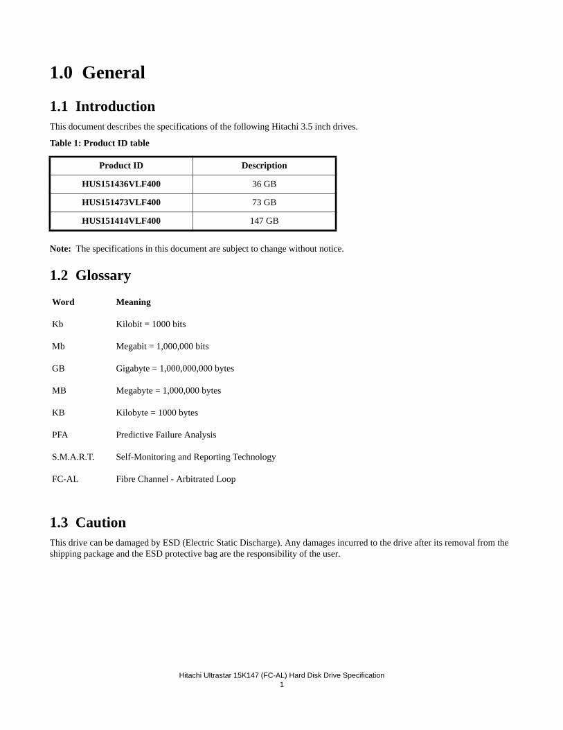
1.1 IntroductionThis document describes the specifications of the following Hitachi 3.5 inch drives.
Table 1: Product ID table
Note: The specifications in this document are subject to change without notice.
1.2 Glossary
Word Meaning
Kb Kilobit = 1000 bits
Mb Megabit = 1,000,000 bits
GB Gigabyte = 1,000,000,000 bytes
MB Megabyte = 1,000,000 bytes
KB Kilobyte = 1000 bytes
PFA Predictive Failure Analysis
S.M.A.R.T. Self-Monitoring and Reporting Technology
FC-AL Fibre Channel - Arbitrated Loop
1.3 CautionThis drive can be damaged by ESD (Electric Static Discharge). Any damages incurred to the drive after its removal from the shipping package and the ESD protective bag are the responsibility of the user.
Product ID Description
HUS151436VLF400 36 GB
HUS151473VLF400 73 GB
HUS151414VLF400 147 GB

Hitachi Ultrastar 15K147 (FC-AL) Hard Disk Drive Specification2
Hitachi Ultrastar 15K147 (FC-AL) Hard Disk Drive Specification3
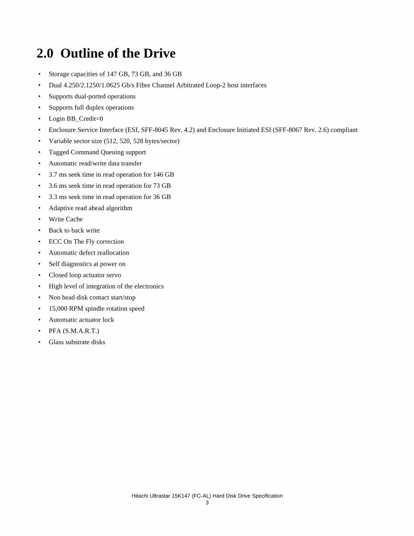
2.0 Outline of the Drive• Storage capacities of 147 GB, 73 GB, and 36 GB
• Dual 4.250/2.1250/1.0625 Gb/s Fibre Channel Arbitrated Loop-2 host interfaces
• Supports dual-ported operations
• Supports full duplex operations
• Login BB_Credit=0
• Enclosure Service Interface (ESI, SFF-8045 Rev. 4.2) and Enclosure Initiated ESI (SFF-8067 Rev. 2.6) compliant
• Variable sector size (512, 520, 528 bytes/sector)
• Tagged Command Queuing support
• Automatic read/write data transfer
• 3.7 ms seek time in read operation for 146 GB
• 3.6 ms seek time in read operation for 73 GB
• 3.3 ms seek time in read operation for 36 GB
• Adaptive read ahead algorithm
• Write Cache
• Back to back write
• ECC On The Fly correction
• Automatic defect reallocation
• Self diagnostics at power on
• Closed loop actuator servo
• High level of integration of the electronics
• Non head disk contact start/stop
• 15,000 RPM spindle rotation speed
• Automatic actuator lock
• PFA (S.M.A.R.T.)
• Glass substrate disks

Hitachi Ultrastar 15K147 (FC-AL) Hard Disk Drive Specification4
Hitachi Ultrastar 15K147 (FC-AL) Hard Disk Drive Specification5
3.0 Fixed-disk Subsystem Description
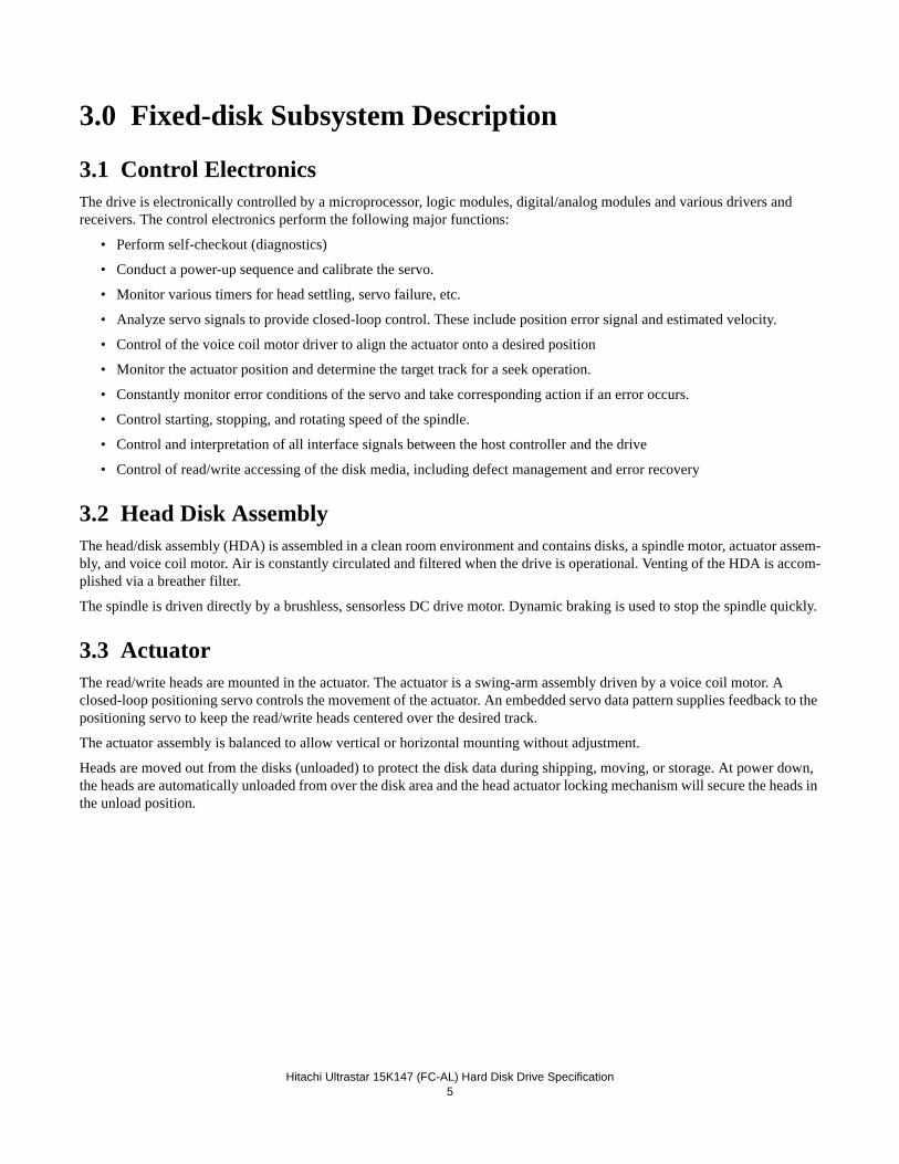
3.1 Control ElectronicsThe drive is electronically controlled by a microprocessor, logic modules, digital/analog modules and various drivers and receivers. The control electronics perform the following major functions:
• Perform self-checkout (diagnostics)
• Conduct a power-up sequence and calibrate the servo.
• Monitor various timers for head settling, servo failure, etc.
• Analyze servo signals to provide closed-loop control. These include position error signal and estimated velocity.
• Control of the voice coil motor driver to align the actuator onto a desired position
• Monitor the actuator position and determine the target track for a seek operation.
• Constantly monitor error conditions of the servo and take corresponding action if an error occurs.
• Control starting, stopping, and rotating speed of the spindle.
• Control and interpretation of all interface signals between the host controller and the drive
• Control of read/write accessing of the disk media, including defect management and error recovery
3.2 Head Disk AssemblyThe head/disk assembly (HDA) is assembled in a clean room environment and contains disks, a spindle motor, actuator assem-bly, and voice coil motor. Air is constantly circulated and filtered when the drive is operational. Venting of the HDA is accom-plished via a breather filter.
The spindle is driven directly by a brushless, sensorless DC drive motor. Dynamic braking is used to stop the spindle quickly.
3.3 ActuatorThe read/write heads are mounted in the actuator. The actuator is a swing-arm assembly driven by a voice coil motor. A closed-loop positioning servo controls the movement of the actuator. An embedded servo data pattern supplies feedback to the positioning servo to keep the read/write heads centered over the desired track.
The actuator assembly is balanced to allow vertical or horizontal mounting without adjustment.
Heads are moved out from the disks (unloaded) to protect the disk data during shipping, moving, or storage. At power down, the heads are automatically unloaded from over the disk area and the head actuator locking mechanism will secure the heads in the unload position.

Hitachi Ultrastar 15K147 (FC-AL) Hard Disk Drive Specification6
Hitachi Ultrastar 15K147 (FC-AL) Hard Disk Drive Specification7
4.0 Drive Characteristics
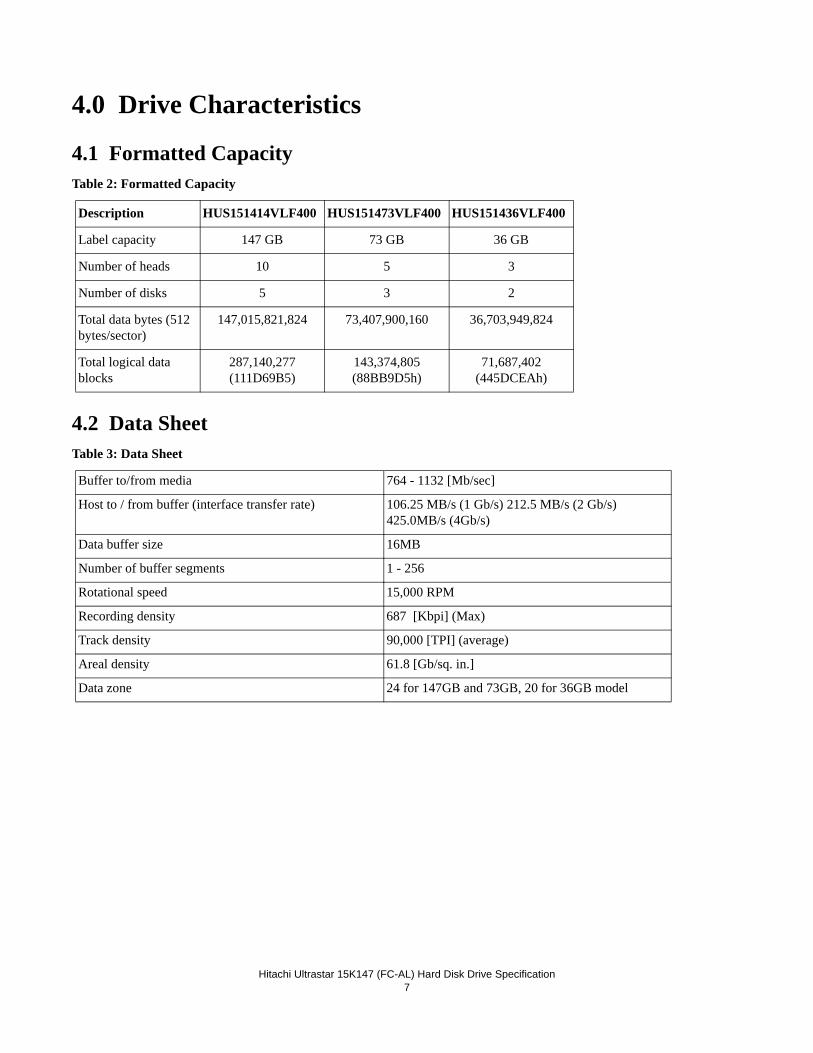
4.1 Formatted CapacityTable 2: Formatted Capacity
4.2 Data SheetTable 3: Data Sheet
Description HUS151414VLF400 HUS151473VLF400 HUS151436VLF400
Label capacity 147 GB 73 GB 36 GB
Number of heads 10 5 3
Number of disks 5 3 2
Total data bytes (512 bytes/sector)
147,015,821,824 73,407,900,160 36,703,949,824
Total logical data blocks
287,140,277 (111D69B5)
143,374,805(88BB9D5h)
71,687,402(445DCEAh)
Buffer to/from media 764 - 1132 [Mb/sec]
Host to / from buffer (interface transfer rate) 106.25 MB/s (1 Gb/s) 212.5 MB/s (2 Gb/s) 425.0MB/s (4Gb/s)
Data buffer size 16MB
Number of buffer segments 1 - 256
Rotational speed 15,000 RPM
Recording density 687 [Kbpi] (Max)
Track density 90,000 [TPI] (average)
Areal density 61.8 [Gb/sq. in.]
Data zone 24 for 147GB and 73GB, 20 for 36GB model
Hitachi Ultrastar 15K147 (FC-AL) Hard Disk Drive Specification8
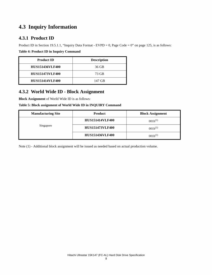
4.3 Inquiry Information
4.3.1 Product IDProduct ID in Section 19.5.1.1, “Inquiry Data Format - EVPD = 0, Page Code = 0” on page 125, is as follows:
Table 4: Product ID in Inquiry Command
4.3.2 World Wide ID - Block AssignmentBlock Assignment of World Wide ID is as follows:
Table 5: Block assignment of World Wide ID in INQUIRY Command
Note (1) - Additional block assignment will be issued as needed based on actual production volume.
Product ID Description
HUS151436VLF400 36 GB
HUS151473VLF400 73 GB
HUS151414VLF400 147 GB
Manufacturing Site Product Block Assignment
Singapore
HUS151414VLF400 001h(1)
HUS151473VLF400 001h(1)
HUS151436VLF400 001h(1)
Hitachi Ultrastar 15K147 (FC-AL) Hard Disk Drive Specification9
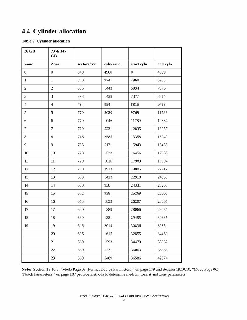
4.4 Cylinder allocationTable 6: Cylinder allocation
Note: Section 19.10.5, “Mode Page 03 (Format Device Parameters)” on page 179 and Section 19.10.10, “Mode Page 0C (Notch Parameters)” on page 187 provide methods to determine medium format and zone parameters.
36 GB 73 & 147 GB
Zone Zone sectors/trk cyln/zone start cyln end cyln
0 0 840 4960 0 4959
1 1 840 974 4960 5933
2 2 805 1443 5934 7376
3 3 793 1438 7377 8814
4 4 784 954 8815 9768
5 5 770 2020 9769 11788
6 6 770 1046 11789 12834
7 7 760 523 12835 13357
8 8 746 2585 13358 15942
9 9 735 513 15943 16455
10 10 728 1533 16456 17988
11 11 720 1016 17989 19004
12 12 700 3913 19005 22917
13 13 680 1413 22918 24330
14 14 680 938 24331 25268
15 15 672 938 25269 26206
16 16 653 1859 26207 28065
17 17 640 1389 28066 29454
18 18 630 1381 29455 30835
19 19 616 2019 30836 32854
20 606 1615 32855 34469
21 560 1593 34470 36062
22 560 523 36063 36585
23 560 5489 36586 42074
Hitachi Ultrastar 15K147 (FC-AL) Hard Disk Drive Specification10
4.5 Performance characteristicsDrive performance is characterized by the following parameters:
•Command overhead•Mechanical head positioning
- Seek time
- Latency•Data transfer speed•Buffering operation (read ahead/write cache)
Note: All the above parameters contribute to drive performance. There are other parameters that contribute to the perfor-mance of the actual system. This specification tries to define the bare drive characteristics, not system throughput, which depends on the system and the application.
Hitachi Ultrastar 15K147 (FC-AL) Hard Disk Drive Specification11
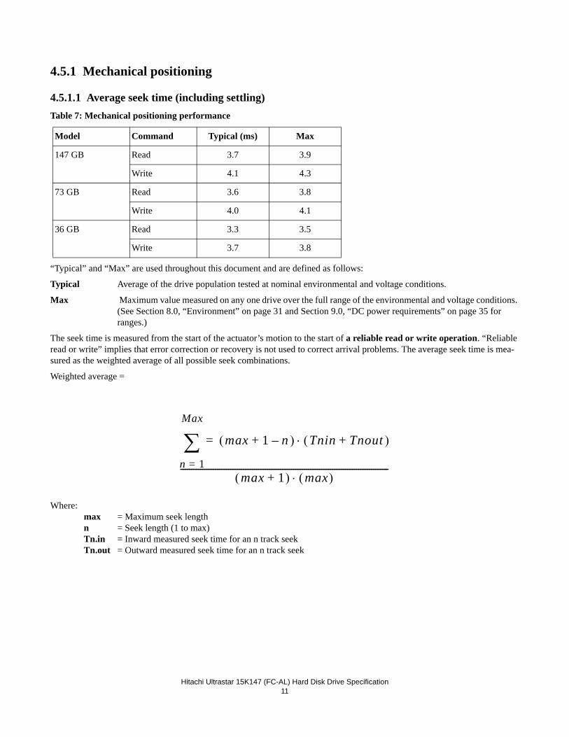
4.5.1 Mechanical positioning
4.5.1.1 Average seek time (including settling)Table 7: Mechanical positioning performance
“Typical” and “Max” are used throughout this document and are defined as follows:
Typical Average of the drive population tested at nominal environmental and voltage conditions.
Max Maximum value measured on any one drive over the full range of the environmental and voltage conditions. (See Section 8.0, “Environment” on page 31 and Section 9.0, “DC power requirements” on page 35 for ranges.)
The seek time is measured from the start of the actuator’s motion to the start of a reliable read or write operation. “Reliable read or write” implies that error correction or recovery is not used to correct arrival problems. The average seek time is mea-sured as the weighted average of all possible seek combinations.
Weighted average =
Where: max = Maximum seek length n = Seek length (1 to max) Tn.in = Inward measured seek time for an n track seek Tn.out = Outward measured seek time for an n track seek
Model Command Typical (ms) Max
147 GB Read 3.7 3.9
Write 4.1 4.3
73 GB Read 3.6 3.8
Write 4.0 4.1
36 GB Read 3.3 3.5
Write 3.7 3.8
max 1 n–+ ) Tnin Tnout+(⋅( )=
n 1=
Max
∑max 1+( ) max( )⋅
------------------------------------------------------------------------------------------------
Hitachi Ultrastar 15K147 (FC-AL) Hard Disk Drive Specification12
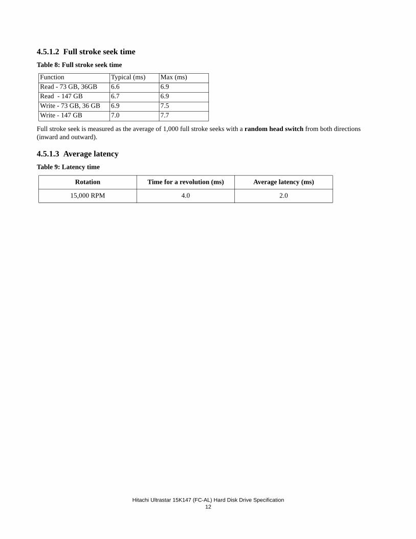
4.5.1.2 Full stroke seek timeTable 8: Full stroke seek time
Full stroke seek is measured as the average of 1,000 full stroke seeks with a random head switch from both directions (inward and outward).
4.5.1.3 Average latencyTable 9: Latency time
Function Typical (ms) Max (ms)Read - 73 GB, 36GB 6.6 6.9Read - 147 GB 6.7 6.9Write - 73 GB, 36 GB 6.9 7.5Write - 147 GB 7.0 7.7
Rotation Time for a revolution (ms) Average latency (ms)
15,000 RPM 4.0 2.0
Hitachi Ultrastar 15K147 (FC-AL) Hard Disk Drive Specification13
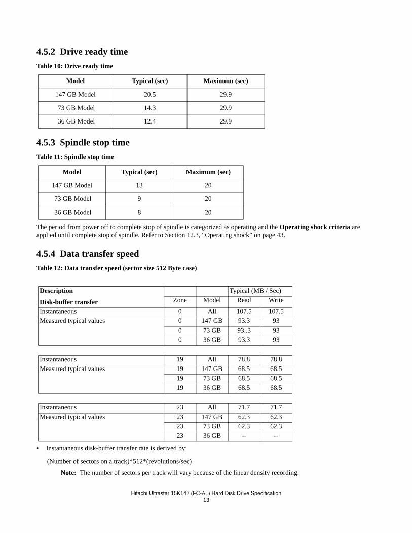
4.5.2 Drive ready timeTable 10: Drive ready time
4.5.3 Spindle stop timeTable 11: Spindle stop time
The period from power off to complete stop of spindle is categorized as operating and the Operating shock criteria are applied until complete stop of spindle. Refer to Section 12.3, “Operating shock” on page 43.
4.5.4 Data transfer speedTable 12: Data transfer speed (sector size 512 Byte case)
• Instantaneous disk-buffer transfer rate is derived by:
(Number of sectors on a track)*512*(revolutions/sec)
Note: The number of sectors per track will vary because of the linear density recording.
Model Typical (sec) Maximum (sec)
147 GB Model 20.5 29.9
73 GB Model 14.3 29.9
36 GB Model 12.4 29.9
Model Typical (sec) Maximum (sec)
147 GB Model 13 20
73 GB Model 9 20
36 GB Model 8 20
Description
Disk-buffer transfer
Typical (MB / Sec)Zone Model Read Write
Instantaneous 0 All 107.5 107.5Measured typical values 0 147 GB 93.3 93
0 73 GB 93..3 930 36 GB 93.3 93
Instantaneous 19 All 78.8 78.8Measured typical values 19 147 GB 68.5 68.5
19 73 GB 68.5 68.519 36 GB 68.5 68.5
Instantaneous 23 All 71.7 71.7Measured typical values 23 147 GB 62.3 62.3
23 73 GB 62.3 62.323 36 GB -- --
Hitachi Ultrastar 15K147 (FC-AL) Hard Disk Drive Specification14
• Sustained disk-buffer transfer rate is defined by considering head/cylinder change time. This gives a local average data transfer rate. It is derived by.
4.5.5 Buffering operation (read ahead/write cache)This hard disk drive has a buffer for read ahead.
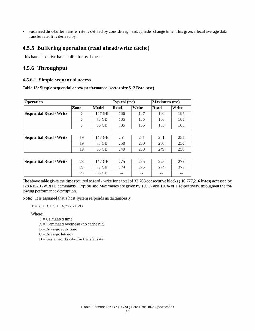
4.5.6 Throughput
4.5.6.1 Simple sequential accessTable 13: Simple sequential access performance (sector size 512 Byte case)
The above table gives the time required to read / write for a total of 32,768 consecutive blocks ( 16,777,216 bytes) accessed by 128 READ /WRITE commands. Typical and Max values are given by 100 % and 110% of T respectively, throughout the fol-lowing performance description.
Note: It is assumed that a host system responds instantaneously.
T = A + B + C + 16,777,216/D
Where: T = Calculated time A = Command overhead (no cache hit) B = Average seek time C = Average latency D = Sustained disk-buffer transfer rate
Operation Typical (ms) Maximum (ms)Zone Model Read Write Read Write
Sequential Read / Write 0 147 GB 186 187 186 1870 73 GB 185 185 186 1850 36 GB 185 185 185 185
Sequential Read / Write 19 147 GB 251 251 251 25119 73 GB 250 250 250 25019 36 GB 249 250 249 250
Sequential Read / Write 23 147 GB 275 275 275 27523 73 GB 274 275 274 27523 36 GB -- -- -- --
Hitachi Ultrastar 15K147 (FC-AL) Hard Disk Drive Specification15
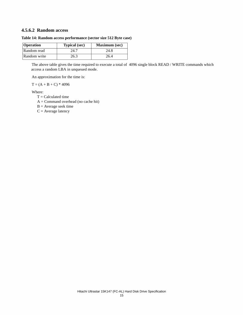
4.5.6.2 Random accessTable 14: Random access performance (sector size 512 Byte case)
The above table gives the time required to execute a total of 4096 single block READ / WRITE commands which access a random LBA in unqueued mode.
An approximation for the time is:
T = (A + B + C) * 4096
Where: T = Calculated time A = Command overhead (no cache hit) B = Average seek time C = Average latency
Operation Typical (sec) Maximum (sec)Random read 24.7 24.8Random write 26.3 26.4

Hitachi Ultrastar 15K147 (FC-AL) Hard Disk Drive Specification16
Hitachi Ultrastar 15K147 (FC-AL) Hard Disk Drive Specification17
5.0 Data IntegrityThe drive retains recorded information under all non-write operations.
No more than one sector can be lost by power down during a write operation while write cache is disabled. If power down occurs before completion of a data transfer from write cache to disk while write cache is enabled, the data remaining in the write cache will be lost. To prevent this data loss at power off, the following action is recommended:
• Confirm successful completion of a SYNCHRONIZE CACHE (35h) command
5.1 Equipment StatusEquipment status is available to the host system any time the drive is not ready to READ, WRITE or SEEK. This status nor-mally exists at power-on time and will be maintained until the following conditions are satisfied:
• Access recalibration/tuning is complete• Spindle speed meets requirements for reliable operations• Self-check of drive is complete
Appropriate error status is made available to the host system if any of the following conditions occur after the drive has become ready:
• Spindle speed goes outside of requirements for reliable operation• “Write fault” is detected
5.2 Error Recovery ProcedureErrors occurring with the drive are handled by the error recovery procedure.
Errors that are uncorrectable after application of the error recovery procedures are reported to the host system as non-recover-able errors.

Hitachi Ultrastar 15K147 (FC-AL) Hard Disk Drive Specification18
Hitachi Ultrastar 15K147 (FC-AL) Hard Disk Drive Specification19
6.0 Physical FormatMedia defects are remapped to the next available sector during the Format Process in manufacturing. The mapping from Log-ical Block Address (LBA) to the physical Block locations is calculated using internally maintained tables.
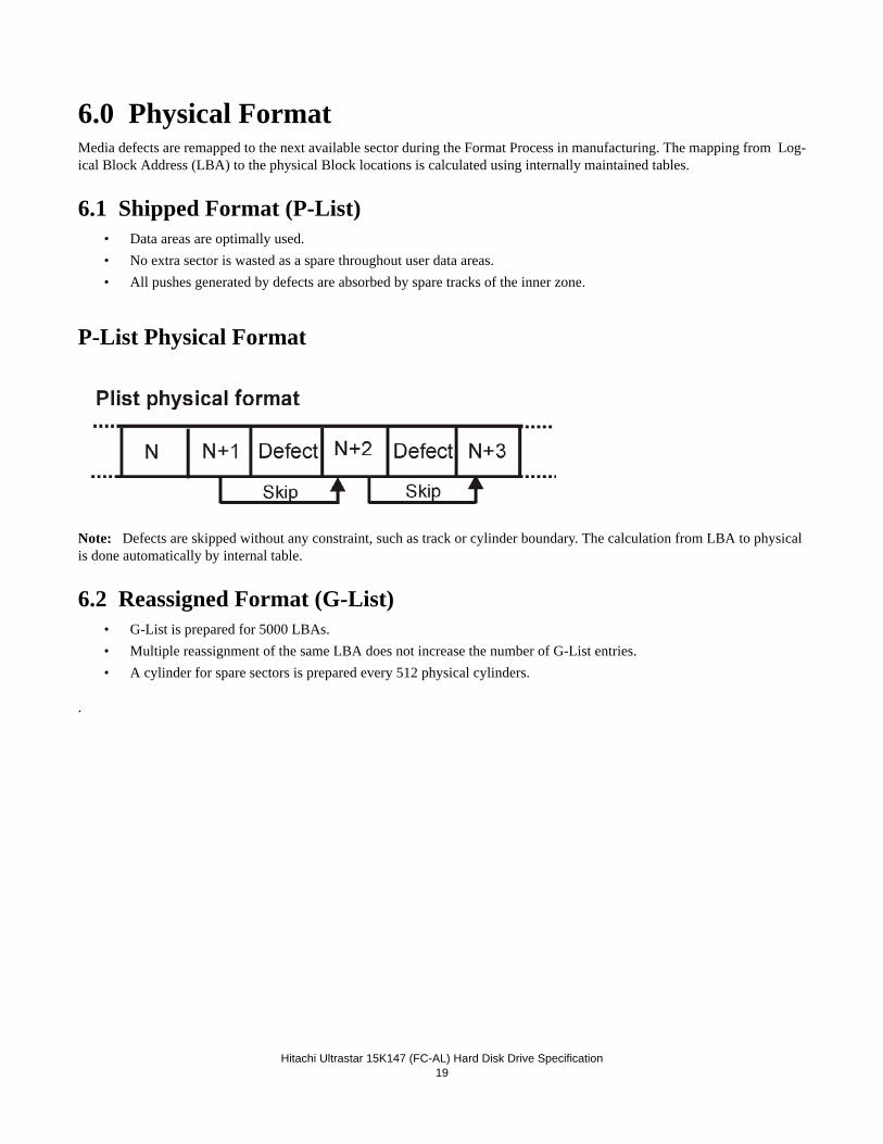
6.1 Shipped Format (P-List)• Data areas are optimally used.• No extra sector is wasted as a spare throughout user data areas.• All pushes generated by defects are absorbed by spare tracks of the inner zone.
P-List Physical Format
Note: Defects are skipped without any constraint, such as track or cylinder boundary. The calculation from LBA to physical is done automatically by internal table.
6.2 Reassigned Format (G-List)• G-List is prepared for 5000 LBAs.• Multiple reassignment of the same LBA does not increase the number of G-List entries.• A cylinder for spare sectors is prepared every 512 physical cylinders.
.

Hitachi Ultrastar 15K147 (FC-AL) Hard Disk Drive Specification20
Hitachi Ultrastar 15K147 (FC-AL) Hard Disk Drive Specification21
7.0 Electrical Interface
7.1 FC-AL ConnectorThe drive uses the 40 pin SCA-2 connector defined by the SFF-8045 specification and the SFF-8067 specification. The only difference between SFF-8045 and SFF-8067 is the Enclosure Service Interface. The drive will 'discover' the level of Enclosure Service Interface supported by the enclosure, and use the proper level for enclosure communication. This 'discovery' process is defined in the SFF-8067 specification.
The connector is expected to be used in an environment which uses a common connector structure for racking disk drives in a cabinet. The connector allows for plugging a drive directly into a backplane by providing the necessary electrical connection. Mechanical stability and device retention must be provided by a mechanism outside the drive.
The signals defined in this connector include:
•Dual ported Fibre Channel In/Out control signals• +5V and +12V power• ID select• Motor start control• LED drive signals• PBC Interlock control• Fibre Channel link rate selection/Hard Reset• Power control
7.1.1 40 pin SCA-2 SFF-8045 FC-AL Connector DefinitionThe drive uses the connector compatible with the SFF-8045 connector specifications. The connector contact assignment is shown in following table.
Table 15: 40-pin Connector Signal Definition
Signal Name Pin # Pin # Signal Name
-ENBL BYP CH1 1 21 12V Charge
12 Volts 2 22 12V Ground
12 Volts 3 23 12V Ground
12 Volts 4 24 +Port 1_In
-Parallel ESI 5* 25 -Port 1_In
-Drive Present 6 26 12V Ground
Ready LED Out 7 27 +Port 2_In
Power Control 8 28 -Port 2_In
Start_1/Mated 9 29 12V Ground
Start_2/Mated 10 30 +Port 1_Out
-ENBL BYP CH2 11 31 -Port 1_Out
Sel_6/-EFW 12* 32 5V Ground
Sel_5/-P_ESI_5 13* 33 +Port 2_Out
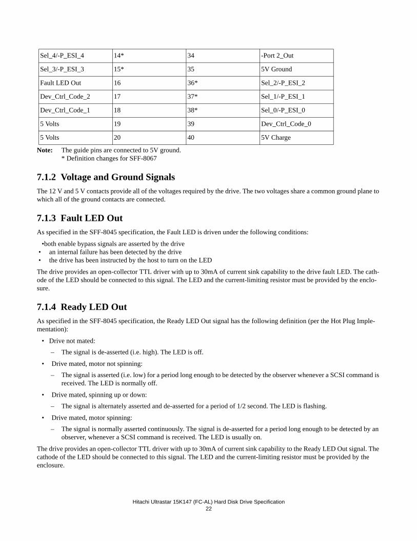
Hitachi Ultrastar 15K147 (FC-AL) Hard Disk Drive Specification22
Note: The guide pins are connected to 5V ground.* Definition changes for SFF-8067
7.1.2 Voltage and Ground SignalsThe 12 V and 5 V contacts provide all of the voltages required by the drive. The two voltages share a common ground plane to which all of the ground contacts are connected.
7.1.3 Fault LED OutAs specified in the SFF-8045 specification, the Fault LED is driven under the following conditions:
•both enable bypass signals are asserted by the drive• an internal failure has been detected by the drive• the drive has been instructed by the host to turn on the LED
The drive provides an open-collector TTL driver with up to 30mA of current sink capability to the drive fault LED. The cath-ode of the LED should be connected to this signal. The LED and the current-limiting resistor must be provided by the enclo-sure.
7.1.4 Ready LED OutAs specified in the SFF-8045 specification, the Ready LED Out signal has the following definition (per the Hot Plug Imple-mentation):
• Drive not mated:
– The signal is de-asserted (i.e. high). The LED is off.
• Drive mated, motor not spinning:
– The signal is asserted (i.e. low) for a period long enough to be detected by the observer whenever a SCSI command is received. The LED is normally off.
• Drive mated, spinning up or down:
– The signal is alternately asserted and de-asserted for a period of 1/2 second. The LED is flashing.
• Drive mated, motor spinning:
– The signal is normally asserted continuously. The signal is de-asserted for a period long enough to be detected by an observer, whenever a SCSI command is received. The LED is usually on.
The drive provides an open-collector TTL driver with up to 30mA of current sink capability to the Ready LED Out signal. The cathode of the LED should be connected to this signal. The LED and the current-limiting resistor must be provided by the enclosure.
Sel_4/-P_ESI_4 14* 34 -Port 2_Out
Sel_3/-P_ESI_3 15* 35 5V Ground
Fault LED Out 16 36* Sel_2/-P_ESI_2
Dev_Ctrl_Code_2 17 37* Sel_1/-P_ESI_1
Dev_Ctrl_Code_1 18 38* Sel_0/-P_ESI_0
5 Volts 19 39 Dev_Ctrl_Code_0
5 Volts 20 40 5V Charge
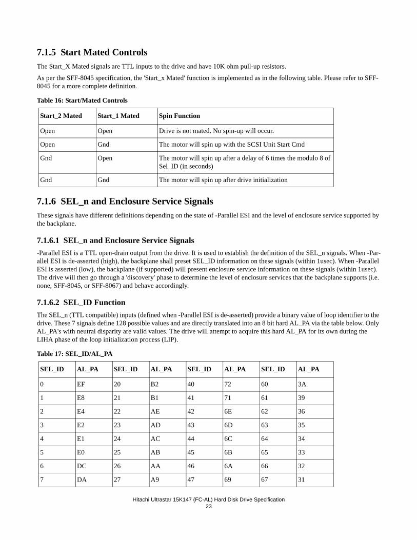
Hitachi Ultrastar 15K147 (FC-AL) Hard Disk Drive Specification23
7.1.5 Start Mated ControlsThe Start_X Mated signals are TTL inputs to the drive and have 10K ohm pull-up resistors.
As per the SFF-8045 specification, the 'Start_x Mated' function is implemented as in the following table. Please refer to SFF-8045 for a more complete definition.
Table 16: Start/Mated Controls
7.1.6 SEL_n and Enclosure Service SignalsThese signals have different definitions depending on the state of -Parallel ESI and the level of enclosure service supported by the backplane.
7.1.6.1 SEL_n and Enclosure Service Signals-Parallel ESI is a TTL open-drain output from the drive. It is used to establish the definition of the SEL_n signals. When -Par-allel ESI is de-asserted (high), the backplane shall preset SEL_ID information on these signals (within 1usec). When -Parallel ESI is asserted (low), the backplane (if supported) will present enclosure service information on these signals (within 1usec). The drive will then go through a 'discovery' phase to determine the level of enclosure services that the backplane supports (i.e. none, SFF-8045, or SFF-8067) and behave accordingly.
7.1.6.2 SEL_ID FunctionThe SEL_n (TTL compatible) inputs (defined when -Parallel ESI is de-asserted) provide a binary value of loop identifier to the drive. These 7 signals define 128 possible values and are directly translated into an 8 bit hard AL_PA via the table below. Only AL_PA's with neutral disparity are valid values. The drive will attempt to acquire this hard AL_PA for its own during the LIHA phase of the loop initialization process (LIP).
Table 17: SEL_ID/AL_PA
Start_2 Mated Start_1 Mated Spin Function
Open Open Drive is not mated. No spin-up will occur.
Open Gnd The motor will spin up with the SCSI Unit Start Cmd
Gnd Open The motor will spin up after a delay of 6 times the modulo 8 of Sel_ID (in seconds)
Gnd Gnd The motor will spin up after drive initialization
SEL_ID AL_PA SEL_ID AL_PA SEL_ID AL_PA SEL_ID AL_PA
0 EF 20 B2 40 72 60 3A
1 E8 21 B1 41 71 61 39
2 E4 22 AE 42 6E 62 36
3 E2 23 AD 43 6D 63 35
4 E1 24 AC 44 6C 64 34
5 E0 25 AB 45 6B 65 33
6 DC 26 AA 46 6A 66 32
7 DA 27 A9 47 69 67 31
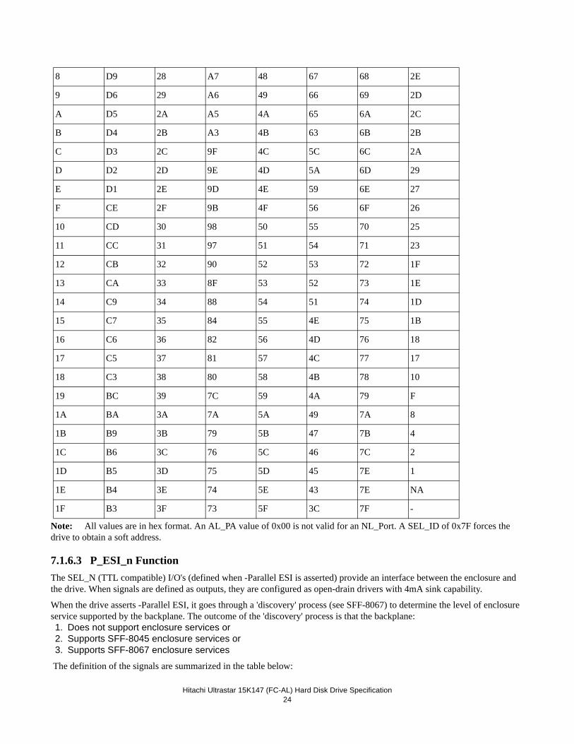
Hitachi Ultrastar 15K147 (FC-AL) Hard Disk Drive Specification24
Note: All values are in hex format. An AL_PA value of 0x00 is not valid for an NL_Port. A SEL_ID of 0x7F forces the drive to obtain a soft address.
7.1.6.3 P_ESI_n FunctionThe SEL_N (TTL compatible) I/O's (defined when -Parallel ESI is asserted) provide an interface between the enclosure and the drive. When signals are defined as outputs, they are configured as open-drain drivers with 4mA sink capability.
When the drive asserts -Parallel ESI, it goes through a 'discovery' process (see SFF-8067) to determine the level of enclosure service supported by the backplane. The outcome of the 'discovery' process is that the backplane:1. Does not support enclosure services or2. Supports SFF-8045 enclosure services or3. Supports SFF-8067 enclosure services
The definition of the signals are summarized in the table below:
8 D9 28 A7 48 67 68 2E
9 D6 29 A6 49 66 69 2D
A D5 2A A5 4A 65 6A 2C
B D4 2B A3 4B 63 6B 2B
C D3 2C 9F 4C 5C 6C 2A
D D2 2D 9E 4D 5A 6D 29
E D1 2E 9D 4E 59 6E 27
F CE 2F 9B 4F 56 6F 26
10 CD 30 98 50 55 70 25
11 CC 31 97 51 54 71 23
12 CB 32 90 52 53 72 1F
13 CA 33 8F 53 52 73 1E
14 C9 34 88 54 51 74 1D
15 C7 35 84 55 4E 75 1B
16 C6 36 82 56 4D 76 18
17 C5 37 81 57 4C 77 17
18 C3 38 80 58 4B 78 10
19 BC 39 7C 59 4A 79 F
1A BA 3A 7A 5A 49 7A 8
1B B9 3B 79 5B 47 7B 4
1C B6 3C 76 5C 46 7C 2
1D B5 3D 75 5D 45 7E 1
1E B4 3E 74 5E 43 7E NA
1F B3 3F 73 5F 3C 7F -
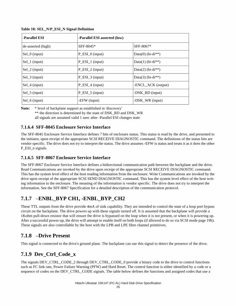
Hitachi Ultrastar 15K147 (FC-AL) Hard Disk Drive Specification25
Table 18: SEL_N/P_ESI_N Signal Definition
Note: * level of backplane support as established in 'discovery'** the direction is determined by the state of DSK_RD and DSK_WRall signals are assumed valid 1 usec after -Parallel ESI changes state
7.1.6.4 SFF-8045 Enclosure Service InterfaceThe SFF-8045 Enclosure Service Interface defines 7 bits of enclosure status. This status is read by the drive, and presented to the initiator, upon receipt of the appropriate SCSI RECEIVE DIAGNOSTIC command. The definitions of the status bits are vendor specific. The drive does not try to interpret the status. The drive assumes -EFW is status and treats it as it does the other P_ESI_n signals.
7.1.6.5 SFF-8067 Enclosure Service InterfaceThe SFF-8067 Enclosure Service Interface defines a bidirectional communication path between the backplane and the drive. Read Communications are invoked by the drive upon receipt of the appropriate SCSI RECEIVE DIAGNOSTIC command. This has the system level effect of the host reading information from the enclosure. Write Communications are invoked by the drive upon receipt of the appropriate SCSI SEND DIAGNOSTIC command. This has the system level effect of the host writ-ing information to the enclosure. The meaning of the information is vendor specific. The drive does not try to interpret the information. See the SFF-8067 Specification for a detailed description of the communication protocol.
7.1.7 –ENBL_BYP CH1, -ENBL_BYP_CH2These TTL outputs from the drive provide 4mA of sink capability. They are intended to control the state of a loop port bypass circuit on the backplane. The drive powers up with these signals turned off. It is assumed that the backplane will provide a 1Kohm pull-down resistor that will ensure the drive is bypassed on the loop when it is not present, or when it is powering up. After a successful power-up, the drive will attempt to enable itself on both loops (if allowed to do so via SCSI mode page 19h). These signals are also controllable by the host with the LPB and LPE fibre channel primitives.
7.1.8 –Drive PresentThis signal is connected to the drive's ground plane. The backplane can use this signal to detect the presence of the drive.
7.1.9 Dev_Ctrl_Code_xThe signals DEV_CTRL_CODE_2 through DEV_CTRL_CODE_0 provide a binary code to the drive to control functions such as FC link rate, Power Failure Warning (PFW) and Hard Reset. The control function is either identified by a code or a sequence of codes on the DEV_CTRL_CODE signals. The table below defines the functions and assigned codes that use a
-Parallel ESI -Parallel ESI asserted (low)
de-asserted (high) SFF-8045* SFF-8067*
Sel_0 (input) P_ESI_0 (input) Data(0) (bi-di**)
Sel_1 (input) P_ESI_1 (input) Data(1) (bi-di**)
Sel_2 (input) P_ESI_2 (input) Data(2) (bi-di**)
Sel_3 (input) P_ESI_3 (input) Data(3) (bi-di**)
Sel_4 (input) P_ESI_4 (input) -ENCL_ACK (output)
Sel_5 (input) P_ESI_5 (input) -DSK_RD (input)
Sel_6 (input) -EFW (input) -DSK_WR (input)
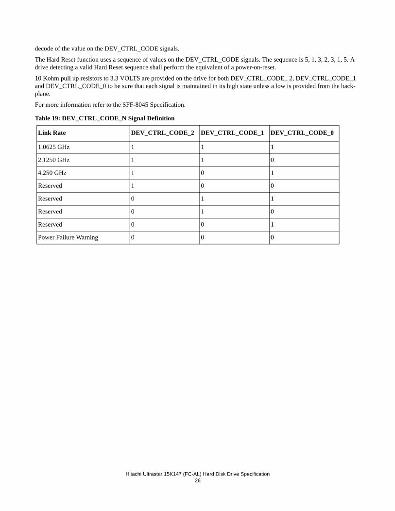
Hitachi Ultrastar 15K147 (FC-AL) Hard Disk Drive Specification26
decode of the value on the DEV_CTRL_CODE signals.
The Hard Reset function uses a sequence of values on the DEV_CTRL_CODE signals. The sequence is 5, 1, 3, 2, 3, 1, 5. A drive detecting a valid Hard Reset sequence shall perform the equivalent of a power-on-reset.
10 Kohm pull up resistors to 3.3 VOLTS are provided on the drive for both DEV_CTRL_CODE_ 2, DEV_CTRL_CODE_1 and DEV_CTRL_CODE_0 to be sure that each signal is maintained in its high state unless a low is provided from the back-plane.
For more information refer to the SFF-8045 Specification.
Table 19: DEV_CTRL_CODE_N Signal Definition
Link Rate DEV_CTRL_CODE_2 DEV_CTRL_CODE_1 DEV_CTRL_CODE_0
1.0625 GHz 1 1 1
2.1250 GHz 1 1 0
4.250 GHz 1 0 1
Reserved 1 0 0
Reserved 0 1 1
Reserved 0 1 0
Reserved 0 0 1
Power Failure Warning 0 0 0
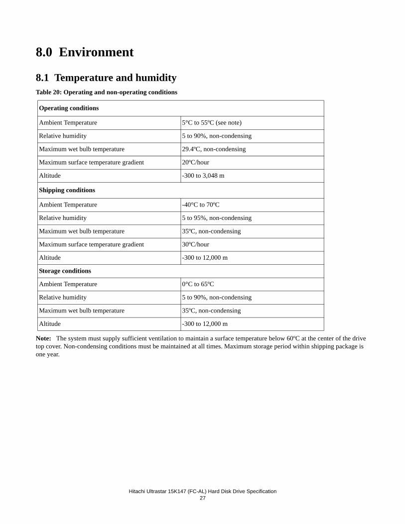
Hitachi Ultrastar 15K147 (FC-AL) Hard Disk Drive Specification27
8.0 Environment
8.1 Temperature and humidityTable 20: Operating and non-operating conditions
Note: The system must supply sufficient ventilation to maintain a surface temperature below 60ºC at the center of the drive top cover. Non-condensing conditions must be maintained at all times. Maximum storage period within shipping package is one year.
Operating conditions
Ambient Temperature 5°C to 55ºC (see note)
Relative humidity 5 to 90%, non-condensing
Maximum wet bulb temperature 29.4ºC, non-condensing
Maximum surface temperature gradient 20ºC/hour
Altitude -300 to 3,048 m
Shipping conditions
Ambient Temperature -40°C to 70ºC
Relative humidity 5 to 95%, non-condensing
Maximum wet bulb temperature 35ºC, non-condensing
Maximum surface temperature gradient 30ºC/hour
Altitude -300 to 12,000 m
Storage conditions
Ambient Temperature 0°C to 65ºC
Relative humidity 5 to 90%, non-condensing
Maximum wet bulb temperature 35ºC, non-condensing
Altitude -300 to 12,000 m
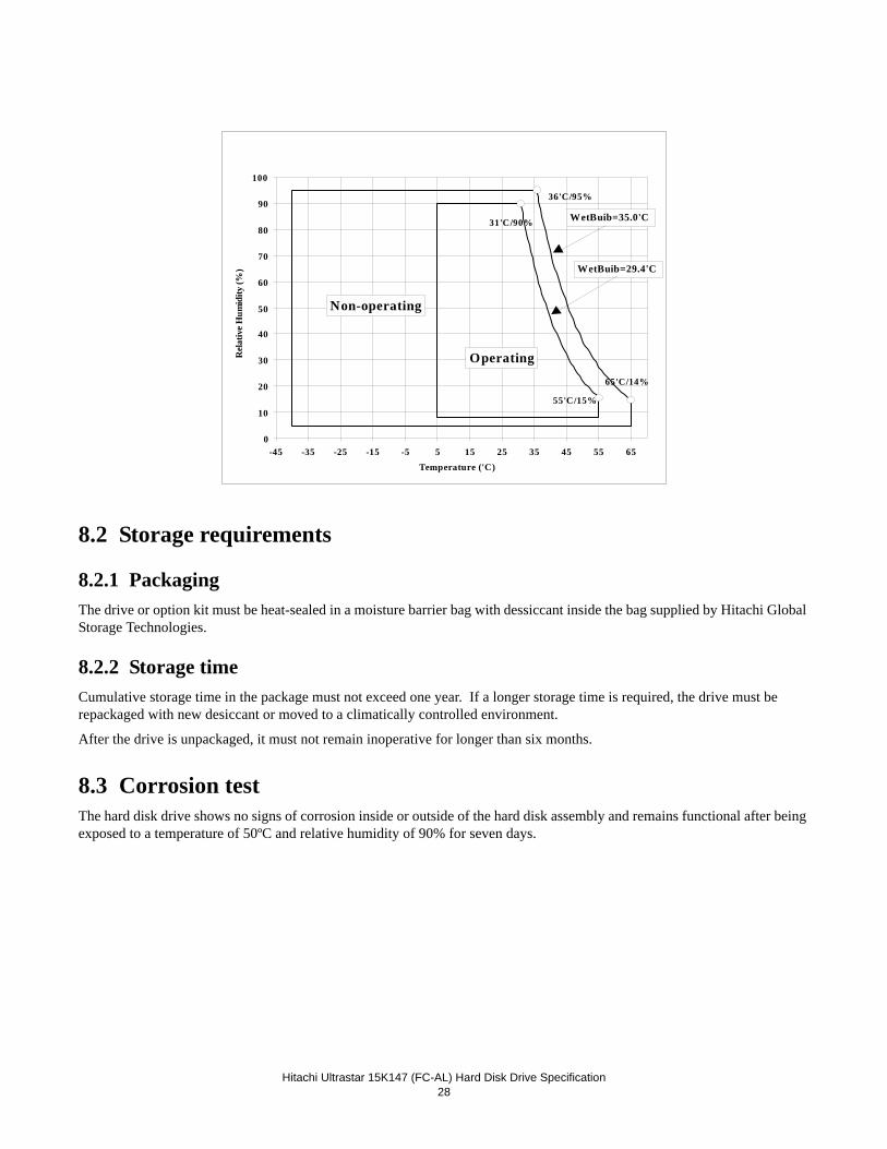
Hitachi Ultrastar 15K147 (FC-AL) Hard Disk Drive Specification28
8.2 Storage requirements
8.2.1 PackagingThe drive or option kit must be heat-sealed in a moisture barrier bag with dessiccant inside the bag supplied by Hitachi Global Storage Technologies.
8.2.2 Storage timeCumulative storage time in the package must not exceed one year. If a longer storage time is required, the drive must be repackaged with new desiccant or moved to a climatically controlled environment.
After the drive is unpackaged, it must not remain inoperative for longer than six months.
8.3 Corrosion testThe hard disk drive shows no signs of corrosion inside or outside of the hard disk assembly and remains functional after being exposed to a temperature of 50ºC and relative humidity of 90% for seven days.
0
10
20
30
40
50
60
70
80
90
100
-45 -35 -25 -15 -5 5 15 25 35 45 55 65Temperature ('C)
Rel
ativ
e H
umid
ity (%
)
Non-operating
Operating
WetBuib=29.4'C
WetBuib=35.0'C
65'C/14%
55'C/15%
31'C/90%
36'C/95%
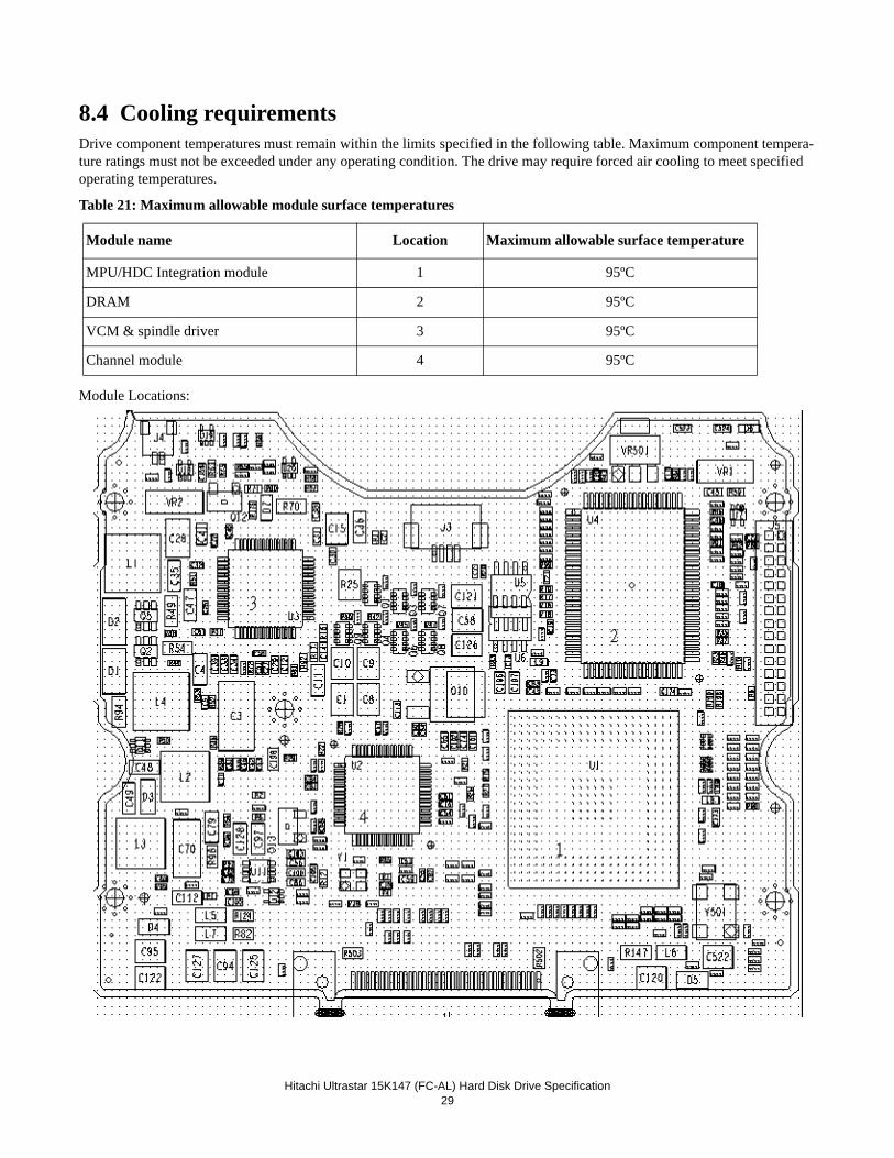
Hitachi Ultrastar 15K147 (FC-AL) Hard Disk Drive Specification29
8.4 Cooling requirementsDrive component temperatures must remain within the limits specified in the following table. Maximum component tempera-ture ratings must not be exceeded under any operating condition. The drive may require forced air cooling to meet specified operating temperatures.
Table 21: Maximum allowable module surface temperatures
Module Locations:
Module name Location Maximum allowable surface temperature
MPU/HDC Integration module 1 95ºC
DRAM 2 95ºC
VCM & spindle driver 3 95ºC
Channel module 4 95ºC

Hitachi Ultrastar 15K147 (FC-AL) Hard Disk Drive Specification30
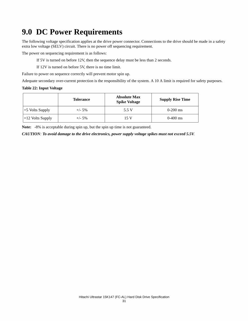
Hitachi Ultrastar 15K147 (FC-AL) Hard Disk Drive Specification31
9.0 DC Power RequirementsThe following voltage specification applies at the drive power connector. Connections to the drive should be made in a safety extra low voltage (SELV) circuit. There is no power off sequencing requirement.
The power on sequencing requirement is as follows:
If 5V is turned on before 12V, then the sequence delay must be less than 2 seconds.
If 12V is turned on before 5V, there is no time limit.
Failure to power on sequence correctly will prevent motor spin up.
Adequate secondary over-current protection is the responsibility of the system. A 10 A limit is required for safety purposes.
Table 22: Input Voltage
Note: -8% is acceptable during spin up, but the spin up time is not guaranteed.
CAUTION: To avoid damage to the drive electronics, power supply voltage spikes must not exceed 5.5V.
Tolerance Absolute Max Spike Voltage Supply Rise Time
+5 Volts Supply +/- 5% 5.5 V 0-200 ms
+12 Volts Supply +/- 5% 15 V 0-400 ms
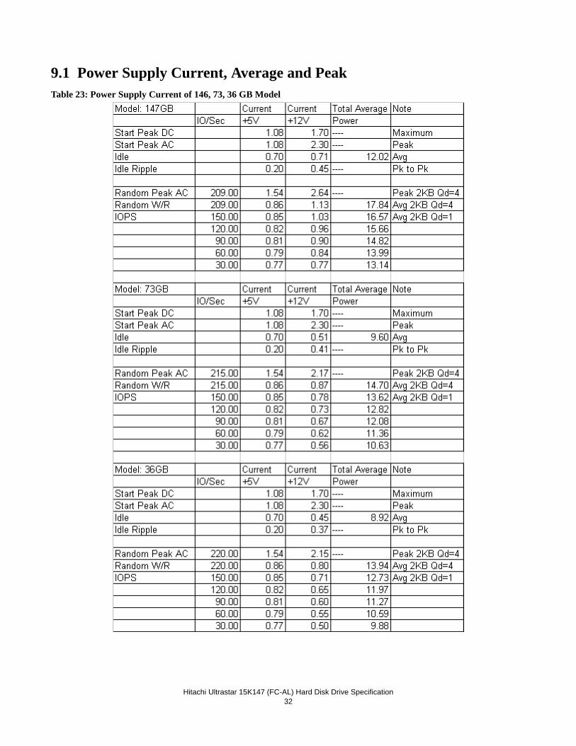
Hitachi Ultrastar 15K147 (FC-AL) Hard Disk Drive Specification32
9.1 Power Supply Current, Average and PeakTable 23: Power Supply Current of 146, 73, 36 GB Model
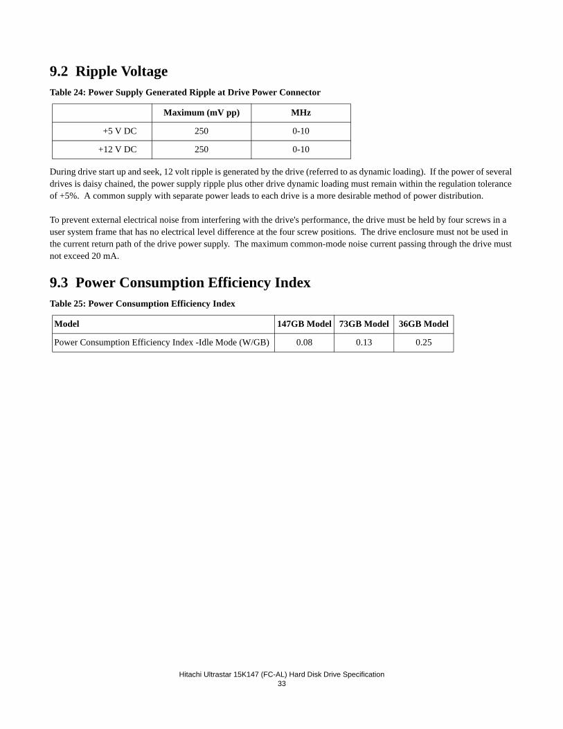
Hitachi Ultrastar 15K147 (FC-AL) Hard Disk Drive Specification33
9.2 Ripple VoltageTable 24: Power Supply Generated Ripple at Drive Power Connector
During drive start up and seek, 12 volt ripple is generated by the drive (referred to as dynamic loading). If the power of several drives is daisy chained, the power supply ripple plus other drive dynamic loading must remain within the regulation tolerance of +5%. A common supply with separate power leads to each drive is a more desirable method of power distribution.
To prevent external electrical noise from interfering with the drive's performance, the drive must be held by four screws in a user system frame that has no electrical level difference at the four screw positions. The drive enclosure must not be used in the current return path of the drive power supply. The maximum common-mode noise current passing through the drive must not exceed 20 mA.
9.3 Power Consumption Efficiency IndexTable 25: Power Consumption Efficiency Index
Maximum (mV pp) MHz
+5 V DC 250 0-10
+12 V DC 250 0-10
Model 147GB Model 73GB Model 36GB Model
Power Consumption Efficiency Index -Idle Mode (W/GB) 0.08 0.13 0.25

Hitachi Ultrastar 15K147 (FC-AL) Hard Disk Drive Specification34
Hitachi Ultrastar 15K147 (FC-AL) Hard Disk Drive Specification35
10.0 Reliability
10.1 Start/Stop CyclesThe drive is designed to withstand a minimum of 50,000 start/stop cycles at ambient environment.
The drive is designed to withstand a minimum of 10,000 start/stop cycles at the operating environment conditions specified in “Environment” on page 27.
10.2 Data ReliabilityThe probability of an uncorrectable data error is 10 in 1x1016 bits read.
ECC implementation:
• 1 symbol = 10 bits
• 1 interleave
• 15 symbols, On-The-Fly correction
• Up to 30 symbols (total) Off-Line correction with burst error information
• LBA seeded 32 bit CRC for ECC miscorrect detection
10.3 Seek errorsA non-recoverable seek/ID miscompare error is defined as a seek operation that cannot be recovered by the error recovery pro-cedure of the drive. The drive reports sense key 04 and sense code 02 for this error.
No drive has more than one non-recoverable seek/ID miscompare error per 100 million seek operations (1 in 1x 10⁸) when operated at the full range of voltage and environmental conditions.
10.4 Failure prediction (PFA/S.M.A.R.T)A recoverable equipment error is an error other than a seek/ID miscompare error or read error that is detected and corrected by the drive error recovery procedure. Examples are Write Fault, Drive Not Ready and internal drive errors.
No drive has more than one recoverable equipment error per 108 READ, 108 WRITE, or 106 SEEK operations when operated at the full range of voltage and environmental conditions.
Non-recoverable equipment errors indicate a defective drive.
10.5 Preventive MaintenanceNone.
10.6 Temperature WarningTemperature Warning is enabled by setting the EWASC (Enable Warning Additional Sense Code) bit to 1 and setting DEXCPT (Disable Exception Control) bit to 0 in Mode Page 1C. For mode page settings, refer to Section 19.10.13, “Mode Page 1C (Informational Exceptions Control)” on page 192. The warning is issued as sense data (Sense Key 01h, Code 0Bh, Qual 01h).
The drive temperature is reported in Log Sense page 2F. Refer to Section 19.7.12, “Log Sense Page 2F” on page 158.

Hitachi Ultrastar 15K147 (FC-AL) Hard Disk Drive Specification36
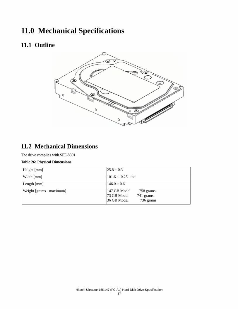
Hitachi Ultrastar 15K147 (FC-AL) Hard Disk Drive Specification37
11.0 Mechanical Specifications
11.1 Outline
11.2 Mechanical DimensionsThe drive complies with SFF-8301.
Table 26: Physical Dimensions
Height [mm] 25.8 ± 0.3
Width [mm] 101.6 ± 0.25 tbd
Length [mm] 146.0 ± 0.6
Weight [grams - maximum] 147 GB Model 758 grams73 GB Model 741 grams36 GB Model 736 grams
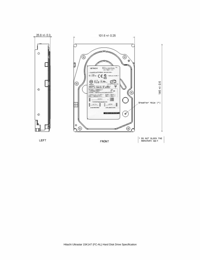
Hitachi Ultrastar 15K147 (FC-AL) Hard Disk Drive Specification
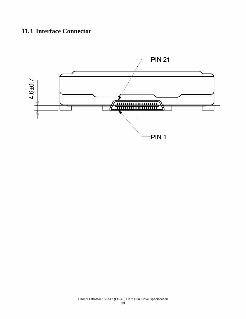
Hitachi Ultrastar 15K147 (FC-AL) Hard Disk Drive Specification39
11.3 Interface Connector
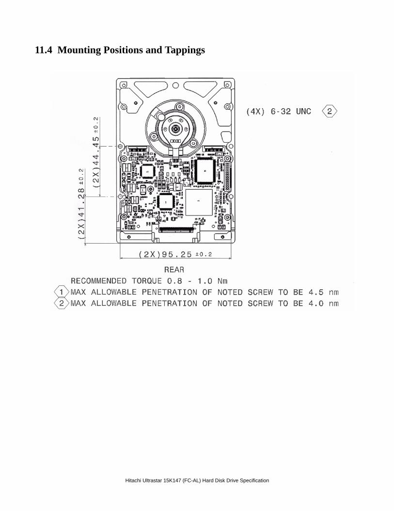
Hitachi Ultrastar 15K147 (FC-AL) Hard Disk Drive Specification
11.4 Mounting Positions and Tappings
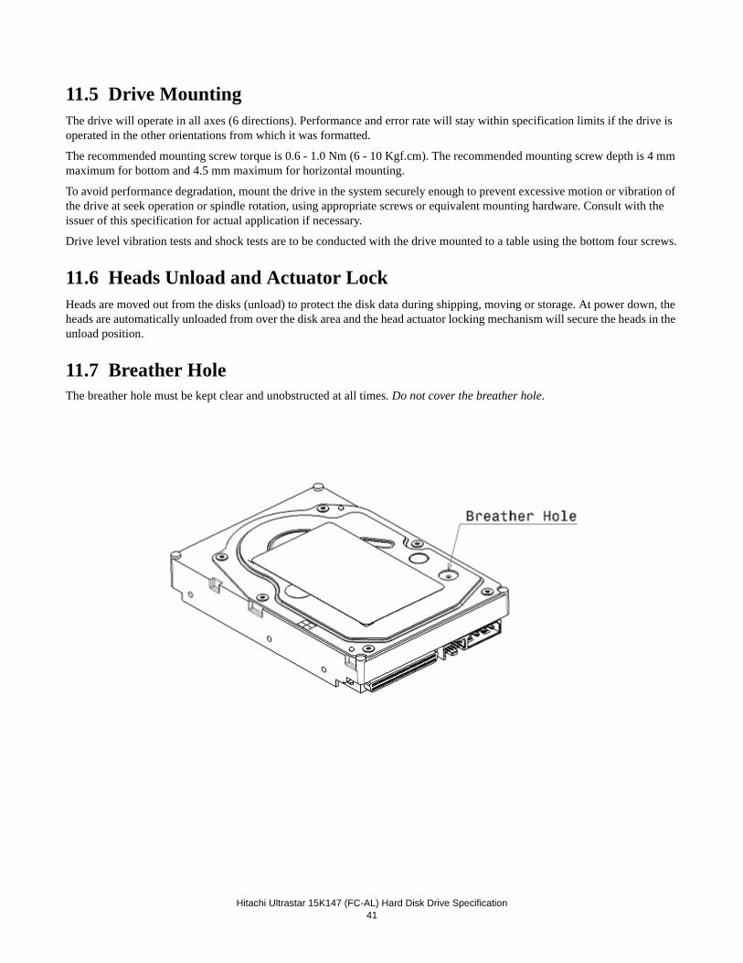
Hitachi Ultrastar 15K147 (FC-AL) Hard Disk Drive Specification41
11.5 Drive MountingThe drive will operate in all axes (6 directions). Performance and error rate will stay within specification limits if the drive is operated in the other orientations from which it was formatted.
The recommended mounting screw torque is 0.6 - 1.0 Nm (6 - 10 Kgf.cm). The recommended mounting screw depth is 4 mm maximum for bottom and 4.5 mm maximum for horizontal mounting.
To avoid performance degradation, mount the drive in the system securely enough to prevent excessive motion or vibration of the drive at seek operation or spindle rotation, using appropriate screws or equivalent mounting hardware. Consult with the issuer of this specification for actual application if necessary.
Drive level vibration tests and shock tests are to be conducted with the drive mounted to a table using the bottom four screws.
11.6 Heads Unload and Actuator LockHeads are moved out from the disks (unload) to protect the disk data during shipping, moving or storage. At power down, the heads are automatically unloaded from over the disk area and the head actuator locking mechanism will secure the heads in the unload position.
11.7 Breather HoleThe breather hole must be kept clear and unobstructed at all times. Do not cover the breather hole.

Hitachi Ultrastar 15K147 (FC-AL) Hard Disk Drive Specification
Hitachi Ultrastar 15K147 (FC-AL) Hard Disk Drive Specification43
12.0 Vibration and ShockAll vibration and shock measurements in this section are made with a drive that has no mounting attachments for the systems. The input power for the measurements is applied to the normal drive mounting points.
12.1 Operating Vibration
12.1.1 Random VibrationThe drive is designed to operate without unrecoverable errors while being subjected to the vibration levels as defined below.
The assessments are carried out during 30 minutes of random vibration using the power spectral density (PSD) levels as fol-lows.
No Errors: 0.4 G RMS, 5-500 Hz, flat PSD profile for each of the three mutually perpendicular axes.
No Data Loss: 1.2 G RMS, 5-500 Hz, flat PSD profile for each of the three mutually perpendicular axes.
Note: The specified levels are measured at the mounting points.
12.1.2 Swept Sine VibrationThe drive will meet the criterion while operating in the respective conditions as described below.
No errors: 0.5 G 0-peak, 5-400-5 Hz sine wave, 0.5 octave/minute sweep rate
No data loss: 0.75 G 0-peak, 5-400-5 Hz sine wave, 0.5 octave/minute sweep rate 1.0 G 0-peak, 5-300-5 Hz sine wave, 0.5 octave/minute sweep rate
12.2 Non-operating VibrationsThe drive will not sustain permanent damage or loss of recorded data after being subjected to the environments as described below.
12.2.1 Random VibrationThe test consists of a random vibration applied for each of the three mutually perpendicular axes at a time duration of ten min-utes per axis.
1.04 G RMS, 5-500 Hz, flat PSD profile
12.2.2 Swept Sine VibrationThe test consists of a swept sine vibration applied for each of the three mutually perpendicular axes.
2.0G 0-peak, 5-500-5 Hz sine wave, 0.5 octave/minute sweep rate
12.3 Operating shockThe drive will meet the criterion while operating in the respective conditions as described below.
No data loss: 15G, 11 ms duration, half sinewave shock pulse
No data loss: 30G, 2 ms duration, half sinewave shock pulse
The shock pulses of each level are applied to the drive, ten pulses for each direction and for all three mutually perpendicular
Hitachi Ultrastar 15K147 (FC-AL) Hard Disk Drive Specification 44
axes. There must be a minimum of thirty seconds delay between shock pulses. The input level is applied to a base plate where the drive is attached using four mounting screws.
12.4 Non-operating shockThe drive will not sustain permanent damage or loss of recorded data after being subjected to the environments as described below.
12.4.1 Half sinewave shock pulse80 G, 11 ms duration, half sinewave pulse
250 G, 2 ms duration, half sinewave pulse
The shocks are applied in each direction of the drive for the three mutually perpendicular axes, one axis at a time. The input level is applied to a base plate where the drive is attached using four mounting screws.
12.4.2 Rotational shock 30,000 radians /second2, 1 ms duration
20,000 radians /second2, 2 ms duration
The shock input is applied around the axis of the actuator pivot. The shock input does not displace the heads from the actuator latched position.
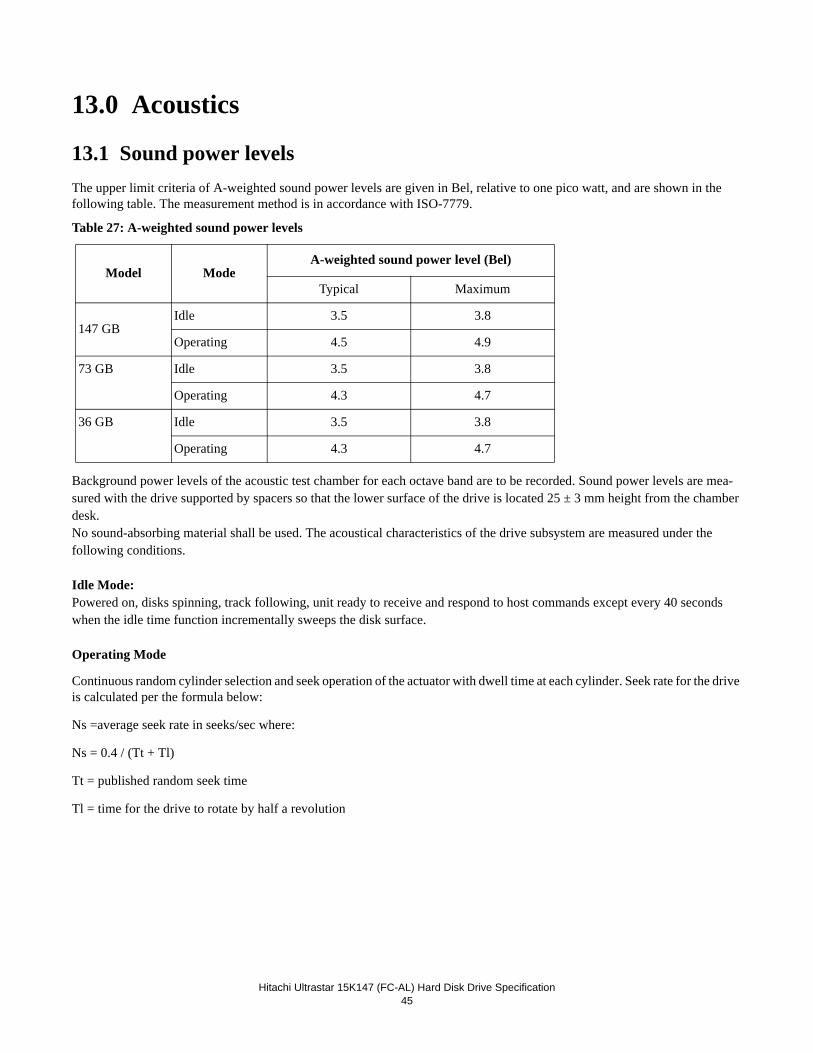
Hitachi Ultrastar 15K147 (FC-AL) Hard Disk Drive Specification
45
13.0 Acoustics
13.1 Sound power levelsThe upper limit criteria of A-weighted sound power levels are given in Bel, relative to one pico watt, and are shown in the following table. The measurement method is in accordance with ISO-7779.
Table 27: A-weighted sound power levels
Background power levels of the acoustic test chamber for each octave band are to be recorded. Sound power levels are mea-sured with the drive supported by spacers so that the lower surface of the drive is located 25 ± 3 mm height from the chamber desk.No sound-absorbing material shall be used. The acoustical characteristics of the drive subsystem are measured under thefollowing conditions.
Idle Mode:Powered on, disks spinning, track following, unit ready to receive and respond to host commands except every 40 seconds when the idle time function incrementally sweeps the disk surface.
Operating Mode
Continuous random cylinder selection and seek operation of the actuator with dwell time at each cylinder. Seek rate for the drive is calculated per the formula below:
Ns =average seek rate in seeks/sec where:
Ns = 0.4 / (Tt + Tl)
Tt = published random seek time
Tl = time for the drive to rotate by half a revolution
Model ModeA-weighted sound power level (Bel)
Typical Maximum
147 GBIdle 3.5 3.8
Operating 4.5 4.9
73 GB Idle 3.5 3.8
Operating 4.3 4.7
36 GB Idle 3.5 3.8
Operating 4.3 4.7

Hitachi Ultrastar 15K147 (FC-AL) Hard Disk Drive Specification46
Hitachi Ultrastar 15K147 (FC-AL) Hard Disk Drive Specification47
14.0 Identification
14.1 LabelsThe following labels are affixed to every hard disk drive shipped from the drive manufacturing location in accordance with appropriate hard disk drive assembly drawing:
• A label containing Hitachi Global Storage Technologies logo, Hitachi part number and the statement “Made by Hita-chi.”, or Hitachi approved equivalent.
• A label containing drive model number, manufacturing date, formatted capacity, country of origin or Hitachi approved equivalent and UL, C-UL, TUV, CE and CTICK logos.
• A bar code label containing the drive serial number.
• A user designed label, per agreement
• Interface definition mark, FC-AL-4 Model
The labels may be integrated with other labels.

Hitachi Ultrastar 15K147 (FC-AL) Hard Disk Drive Specification
48
Hitachi Ultrastar 15K147 (FC-AL) Hard Disk Drive Specification49
15.0 Electromagnetic CompatibilityThe drive, when installed in a suitable enclosure and exercised with a random accessing routine at maximum data rate meets the worldwide EMC requirements listed below.
Hitachi will provide technical support to meet the requirements to comply with the EMC specifications.
• United States Federal Communications Commission (FCC) Rules and Regulations (Class A), Part 15
• Hitachi Corporate Standard C-S 2-0001-005
• CISPR Publication 22; 1993 (Class A)
• CISPR Publication 22; Amendment 1, 1995
• CISPR Publication 22; Amendment 2, 1996
• Electrostatic Discharge Susceptibility limits for a Class 2 ESD environment specified in Hitachi Corporate Standard C-S 2-0001-034.
• Radiated Electromagnetic Susceptibility (RES) as specified in Hitachi Corporate Standard C-S 2-0001-037.

Hitachi Ultrastar 15K147 (FC-AL) Hard Disk Drive Specification
50
Hitachi Ultrastar 15K147 (FC-AL) Hard Disk Drive Specification
51
16.0 StandardsThe following shows the safety standards for different countries.
16.1 UL and C-UL Standard ConformityThe drive is qualified per ULIEC 60950-1: 2001, First Edition for use in Information Technology Equipment, including Elec-tric Business Equipment. The UL recognition, or the C-UL certification, is maintained for the product life. The UL and C-UL recognition mark appears on the drive.
16.2 European Standards ComplianceThe product is certified to EN60950.
16.3 German Safety MarkThe product is approved by TUV on Test requirement: EN 60950, but the GS mark is not applicable to internal devices such as these drives.
16.4 FlammabilityThe printed circuit boards used in this drive are made of material with a UL recognized flammability rating of V-1 or better. The flammability rating is marked or etched on the board. All other parts not considered electrical components are made of material with a UL recognized flammability rating of V-1 or better.
16.5 Corporate Standards ComplianceThis product has been designed to meet the following Corporate Standards:
- NB 3-0501-201 Product Safety, National Requirements-All Countries. - CS 3-0501-070 Electrical, Mechanical and Flammability - NB 3-0501-033 Product Safety National Certification Conformity Requirement - CS 1-9700-020 Eco-Product Design Requirement
Hitachi GST encourages owners of information technology (IT) equipment to responsibly recycle their equipment when it is no longer needed. Hitachi GST offers a variety of programs and services to assist equipment owners in recycling their IT products.

Hitachi Ultrastar 15K147 (FC-AL) Hard Disk Drive Specification
52
Hitachi Ultrastar 15K147 (FC-AL) Hard Disk Drive Specification53
17.0 FC-AL attachmentThis section defines some basic terminology and describes the behavior of the drive when attached to a Fibre Channel Arbi-trated Loop.
17.1 FundamentalsThis section introduces some of the terminology that is used in describing Fibre Channel and FC-AL.
Fibre Channel is logically a bi-directional serial data channel between two Nodes. Nodes are physically connected by a Link; the point of connection between the link and the node is called a Port.
Ports may be connected point-to-point by a single link or by a switching network (Fabric). If the port is part of the Fabric it is called an F_Port, otherwise it is an N_Port.
Fibre Channel is defined in terms of a hierarchy of functions or 'protocol layers'.
• FC-0: Physical Link
• FC-1: Transmission Protocol
• FC-2: Signaling and Framing Protocol
• FC-3: Common Services
• FC-4: Mapping
All layers except FC-4 are defined in
• “Fibre Channel Physical and Signaling Interface (FC-PH)” - ANSI
The Arbitrated Loop is an extension of FC-1 and FC-2 that allows more than two nodes to be connected without the expense of a Fabric. A port that connects to an Arbitrated Loop is generally referred to as an L_Port. However, the terms NL_Port and FL_Port are also used if it is necessary to distinguish whether or not the L_Port is part of a Fabric. FC-AL is defined in:
• “Fibre Channel Arbitrated Loop (FC-AL)” -ANSI
FC-4, the Mapping layer, defines how other communication protocols (e.g. SCSI, IPI-3, HIPPI) may use Fibre Channel func-tions. The FC-4 used by The Drive is SCSI-FCP, which is defined in:
• “Fibre Channel Protocol for SCSI (SCSI-FCP)” -ANSI
The 'Disk Profile', recommends which features from the other documents should and should not be implemented in order to ensure compatibility between devices from different manufacturers. The full title of the Disk Profile is:
• “Fibre Channel Private Loop SCSI Direct Attach (FC-PLDA)” -ANSI
An additional document, the ‘Public Loop Profile’, describes the additional features needed to support communication over a FC Fabric Topology. In addition to communicating with devices on their local loop, Public Loop devices can also communi-cate to devices across a network through the use of a “Fabric Port.” Public Loop behavior is defined in:
• “Fibre Channel - Fabric Loop Attach (FC-FLA)” -ANSI
The Drive complies with the FC-FLA, which makes the following requirements:1. The upper two bytes of the device’s NL_Port ID must not be zero.2. The device must be able to communicate with the Fabric Port i.e., open AL_PA 0x00.
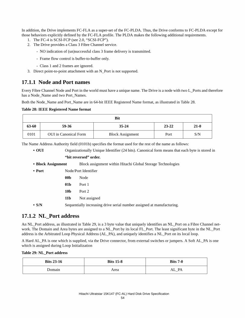
Hitachi Ultratstar 15K147 (FC-AL) Hard Disk Drive Specification54
In addition, the Drive implements FC-FLA as a super-set of the FC-PLDA. Thus, the Drive conforms to FC-PLDA except for those behaviors explicitly defined by the FC-FLA profile. The PLDA makes the following additional requirements.
1. The FC-4 is SCSI-FCP (see 2.0, “SCSI-FCP”). 2. The Drive provides a Class 3 Fibre Channel service.
- NO indication of (un)successful class 3 frame delivery is transmitted.
- Frame flow control is buffer-to-buffer only.
- Class 1 and 2 frames are ignored.3. Direct point-to-point attachment with an N_Port is not supported.
17.1.1 Node and Port names Every Fibre Channel Node and Port in the world must have a unique name. The Drive is a node with two L_Ports and therefore has a Node_Name and two Port_Names.
Both the Node_Name and Port_Name are in 64-bit IEEE Registered Name format, as illustrated in Table 28.
Table 28: IEEE Registered Name format
The Name Address Authority field (0101b) specifies the format used for the rest of the name as follows:• OUI Organizationally Unique Identifier (24 bits). Canonical form means that each byte is stored in
“bit reversed” order.
• Block Assignment Block assignment within Hitachi Global Storage Technologies
• Port Node/Port Identifier
00b Node
01b Port 1
10b Port 2
11b Not assigned
• S/N Sequentially increasing drive serial number assigned at manufacturing.
17.1.2 NL_Port addressAn NL_Port address, as illustrated in Table 29, is a 3 byte value that uniquely identifies an NL_Port on a Fibre Channel net-work. The Domain and Area bytes are assigned to a NL_Port by its local FL_Port. The least significant byte in the NL_Port address is the Arbitrated Loop Physical Address (AL_PA), and uniquely identifies a NL_Port on its local loop.
A Hard AL_PA is one which is supplied, via the Drive connector, from external switches or jumpers. A Soft AL_PA is one which is assigned during Loop Initialization
Table 29: NL_Port address
Bit
63-60 59-36 35-24 23-22 21-0
0101 OUI in Canonical Form Block Assignment Port S/N
Bits 23-16 Bits 15-8 Bits 7-0
Domain Area AL_PA
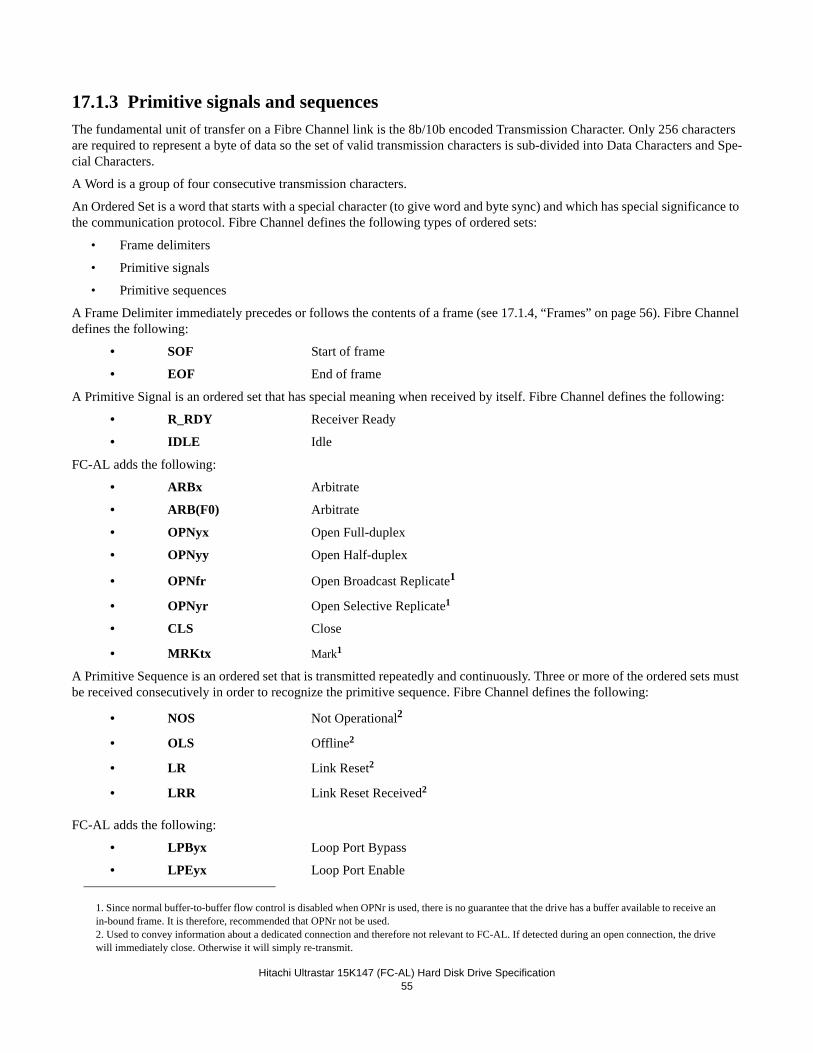
Hitachi Ultrastar 15K147 (FC-AL) Hard Disk Drive Specification55
17.1.3 Primitive signals and sequencesThe fundamental unit of transfer on a Fibre Channel link is the 8b/10b encoded Transmission Character. Only 256 characters are required to represent a byte of data so the set of valid transmission characters is sub-divided into Data Characters and Spe-cial Characters.
A Word is a group of four consecutive transmission characters.
An Ordered Set is a word that starts with a special character (to give word and byte sync) and which has special significance to the communication protocol. Fibre Channel defines the following types of ordered sets:
• Frame delimiters
• Primitive signals
• Primitive sequences
A Frame Delimiter immediately precedes or follows the contents of a frame (see 17.1.4, “Frames” on page 56). Fibre Channel defines the following:
• SOF Start of frame
• EOF End of frame
A Primitive Signal is an ordered set that has special meaning when received by itself. Fibre Channel defines the following:
• R_RDY Receiver Ready
• IDLE Idle
FC-AL adds the following:
• ARBx Arbitrate
• ARB(F0) Arbitrate
• OPNyx Open Full-duplex
• OPNyy Open Half-duplex
• OPNfr Open Broadcast Replicate1
• OPNyr Open Selective Replicate1
• CLS Close
• MRKtx Mark1
A Primitive Sequence is an ordered set that is transmitted repeatedly and continuously. Three or more of the ordered sets must be received consecutively in order to recognize the primitive sequence. Fibre Channel defines the following:
• NOS Not Operational2
• OLS Offline2
• LR Link Reset2
• LRR Link Reset Received2
FC-AL adds the following:
• LPByx Loop Port Bypass
• LPEyx Loop Port Enable
1. Since normal buffer-to-buffer flow control is disabled when OPNr is used, there is no guarantee that the drive has a buffer available to receive an in-bound frame. It is therefore, recommended that OPNr not be used.2. Used to convey information about a dedicated connection and therefore not relevant to FC-AL. If detected during an open connection, the drive will immediately close. Otherwise it will simply re-transmit.
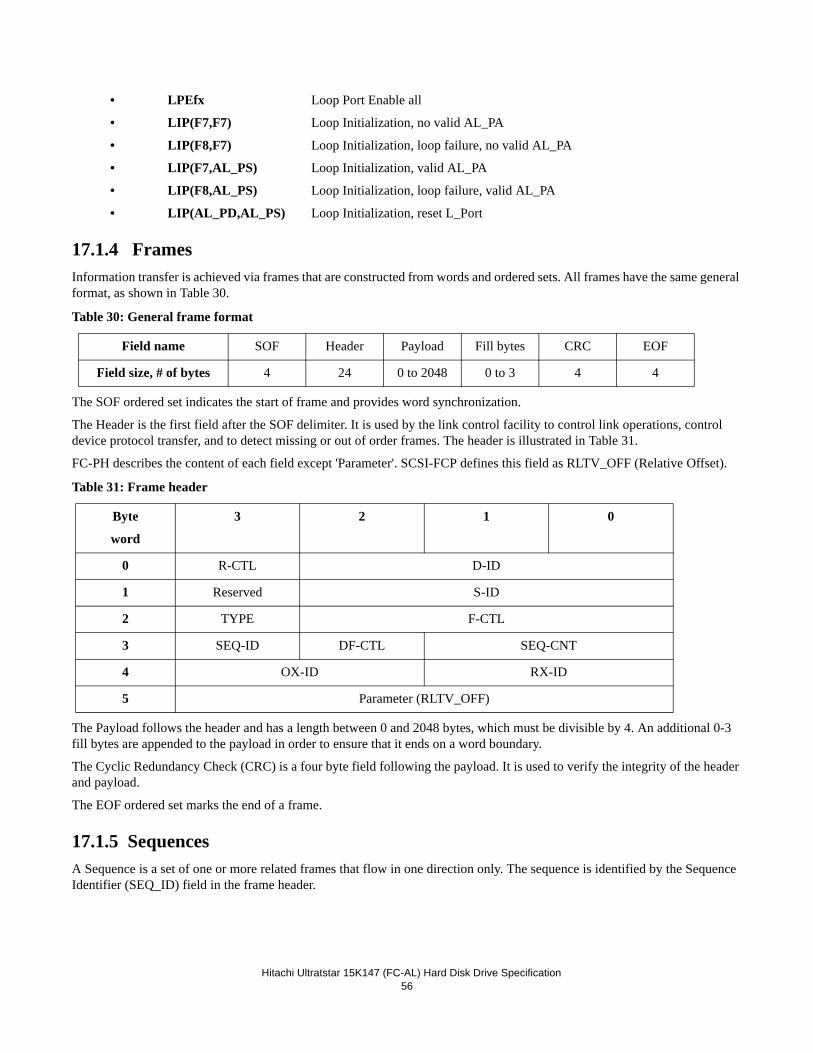
Hitachi Ultratstar 15K147 (FC-AL) Hard Disk Drive Specification56
• LPEfx Loop Port Enable all
• LIP(F7,F7) Loop Initialization, no valid AL_PA
• LIP(F8,F7) Loop Initialization, loop failure, no valid AL_PA
• LIP(F7,AL_PS) Loop Initialization, valid AL_PA
• LIP(F8,AL_PS) Loop Initialization, loop failure, valid AL_PA
• LIP(AL_PD,AL_PS) Loop Initialization, reset L_Port
17.1.4 FramesInformation transfer is achieved via frames that are constructed from words and ordered sets. All frames have the same general format, as shown in Table 30.
Table 30: General frame format
The SOF ordered set indicates the start of frame and provides word synchronization.
The Header is the first field after the SOF delimiter. It is used by the link control facility to control link operations, control device protocol transfer, and to detect missing or out of order frames. The header is illustrated in Table 31.
FC-PH describes the content of each field except 'Parameter'. SCSI-FCP defines this field as RLTV_OFF (Relative Offset).
Table 31: Frame header
The Payload follows the header and has a length between 0 and 2048 bytes, which must be divisible by 4. An additional 0-3 fill bytes are appended to the payload in order to ensure that it ends on a word boundary.
The Cyclic Redundancy Check (CRC) is a four byte field following the payload. It is used to verify the integrity of the header and payload.
The EOF ordered set marks the end of a frame.
17.1.5 SequencesA Sequence is a set of one or more related frames that flow in one direction only. The sequence is identified by the Sequence Identifier (SEQ_ID) field in the frame header.
Field name SOF Header Payload Fill bytes CRC EOF
Field size, # of bytes 4 24 0 to 2048 0 to 3 4 4
Byte
word
3 2 1 0
0 R-CTL D-ID
1 Reserved S-ID
2 TYPE F-CTL
3 SEQ-ID DF-CTL SEQ-CNT
4 OX-ID RX-ID
5 Parameter (RLTV_OFF)
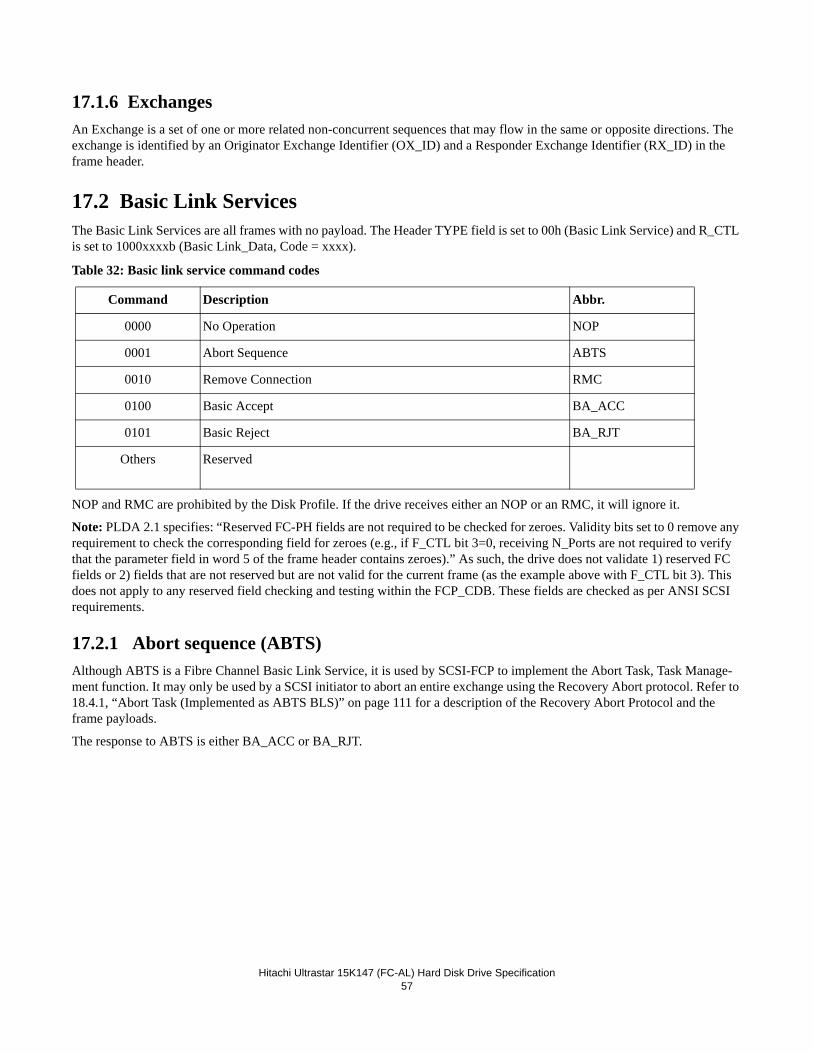
Hitachi Ultrastar 15K147 (FC-AL) Hard Disk Drive Specification57
17.1.6 ExchangesAn Exchange is a set of one or more related non-concurrent sequences that may flow in the same or opposite directions. The exchange is identified by an Originator Exchange Identifier (OX_ID) and a Responder Exchange Identifier (RX_ID) in the frame header.
17.2 Basic Link ServicesThe Basic Link Services are all frames with no payload. The Header TYPE field is set to 00h (Basic Link Service) and R_CTL is set to 1000xxxxb (Basic Link_Data, Code = xxxx).
Table 32: Basic link service command codes
NOP and RMC are prohibited by the Disk Profile. If the drive receives either an NOP or an RMC, it will ignore it.
Note: PLDA 2.1 specifies: “Reserved FC-PH fields are not required to be checked for zeroes. Validity bits set to 0 remove any requirement to check the corresponding field for zeroes (e.g., if F_CTL bit 3=0, receiving N_Ports are not required to verify that the parameter field in word 5 of the frame header contains zeroes).” As such, the drive does not validate 1) reserved FC fields or 2) fields that are not reserved but are not valid for the current frame (as the example above with F_CTL bit 3). This does not apply to any reserved field checking and testing within the FCP_CDB. These fields are checked as per ANSI SCSI requirements.
17.2.1 Abort sequence (ABTS)Although ABTS is a Fibre Channel Basic Link Service, it is used by SCSI-FCP to implement the Abort Task, Task Manage-ment function. It may only be used by a SCSI initiator to abort an entire exchange using the Recovery Abort protocol. Refer to 18.4.1, “Abort Task (Implemented as ABTS BLS)” on page 111 for a description of the Recovery Abort Protocol and the frame payloads.
The response to ABTS is either BA_ACC or BA_RJT.
Command Description Abbr.
0000 No Operation NOP
0001 Abort Sequence ABTS
0010 Remove Connection RMC
0100 Basic Accept BA_ACC
0101 Basic Reject BA_RJT
Others Reserved
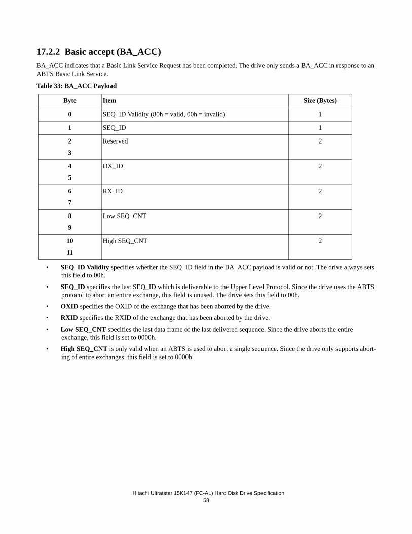
Hitachi Ultratstar 15K147 (FC-AL) Hard Disk Drive Specification58
17.2.2 Basic accept (BA_ACC)BA_ACC indicates that a Basic Link Service Request has been completed. The drive only sends a BA_ACC in response to an ABTS Basic Link Service.
Table 33: BA_ACC Payload
• SEQ_ID Validity specifies whether the SEQ_ID field in the BA_ACC payload is valid or not. The drive always sets this field to 00h.
• SEQ_ID specifies the last SEQ_ID which is deliverable to the Upper Level Protocol. Since the drive uses the ABTS protocol to abort an entire exchange, this field is unused. The drive sets this field to 00h.
• OXID specifies the OXID of the exchange that has been aborted by the drive.
• RXID specifies the RXID of the exchange that has been aborted by the drive.
• Low SEQ_CNT specifies the last data frame of the last delivered sequence. Since the drive aborts the entire exchange, this field is set to 0000h.
• High SEQ_CNT is only valid when an ABTS is used to abort a single sequence. Since the drive only supports abort-ing of entire exchanges, this field is set to 0000h.
Byte Item Size (Bytes)
0 SEQ_ID Validity (80h = valid, 00h = invalid) 1
1 SEQ_ID 1
2
3
Reserved 2
4
5
OX_ID 2
6
7
RX_ID 2
8
9
Low SEQ_CNT 2
10
11
High SEQ_CNT 2
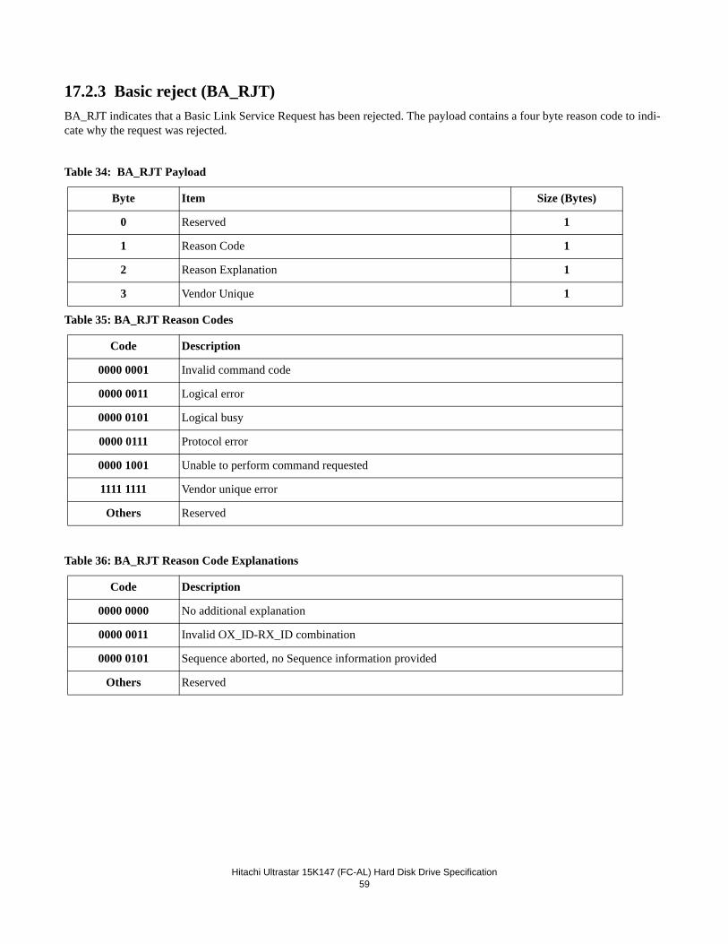
Hitachi Ultrastar 15K147 (FC-AL) Hard Disk Drive Specification59
17.2.3 Basic reject (BA_RJT)BA_RJT indicates that a Basic Link Service Request has been rejected. The payload contains a four byte reason code to indi-cate why the request was rejected.
Table 34: BA_RJT Payload
Table 35: BA_RJT Reason Codes
Table 36: BA_RJT Reason Code Explanations
Byte Item Size (Bytes)
0 Reserved 1
1 Reason Code 1
2 Reason Explanation 1
3 Vendor Unique 1
Code Description
0000 0001 Invalid command code
0000 0011 Logical error
0000 0101 Logical busy
0000 0111 Protocol error
0000 1001 Unable to perform command requested
1111 1111 Vendor unique error
Others Reserved
Code Description
0000 0000 No additional explanation
0000 0011 Invalid OX_ID-RX_ID combination
0000 0101 Sequence aborted, no Sequence information provided
Others Reserved
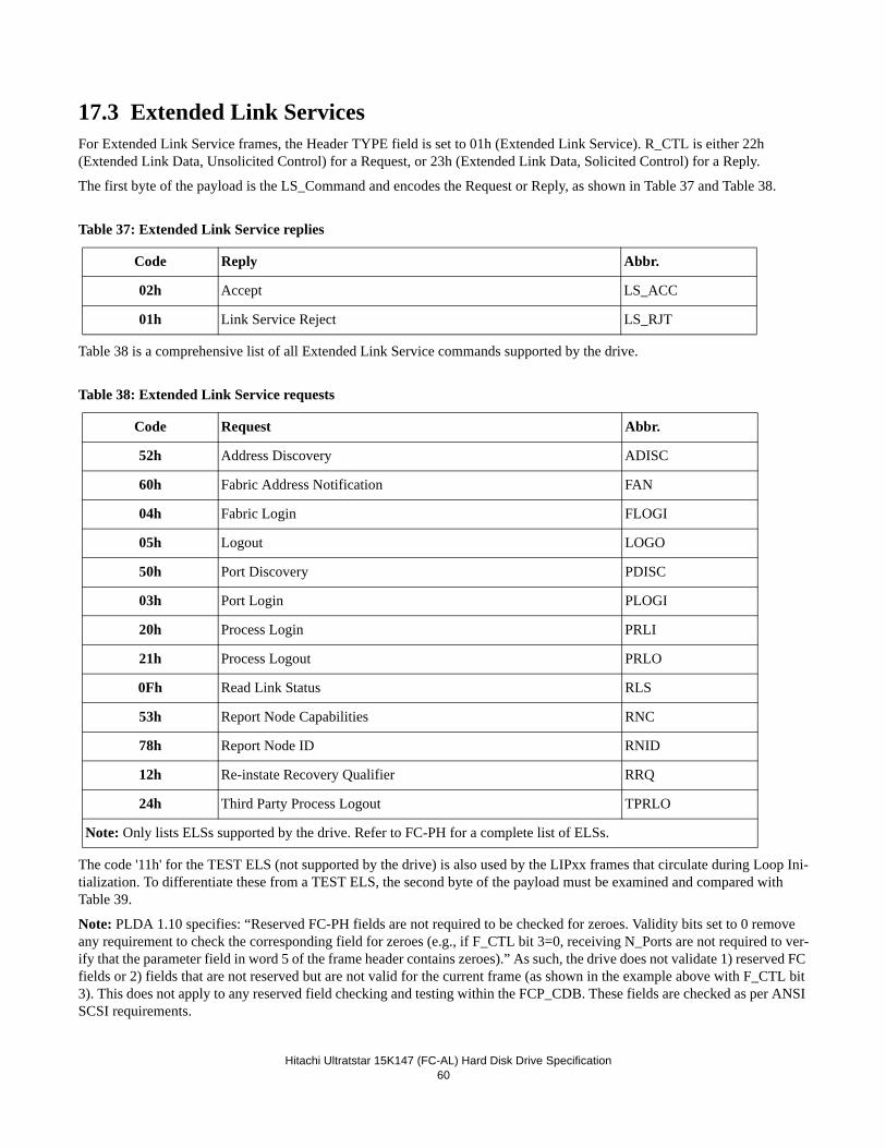
Hitachi Ultratstar 15K147 (FC-AL) Hard Disk Drive Specification60
17.3 Extended Link ServicesFor Extended Link Service frames, the Header TYPE field is set to 01h (Extended Link Service). R_CTL is either 22h (Extended Link Data, Unsolicited Control) for a Request, or 23h (Extended Link Data, Solicited Control) for a Reply.
The first byte of the payload is the LS_Command and encodes the Request or Reply, as shown in Table 37 and Table 38.
Table 37: Extended Link Service replies
Table 38 is a comprehensive list of all Extended Link Service commands supported by the drive.
Table 38: Extended Link Service requests
The code '11h' for the TEST ELS (not supported by the drive) is also used by the LIPxx frames that circulate during Loop Ini-tialization. To differentiate these from a TEST ELS, the second byte of the payload must be examined and compared with Table 39.
Note: PLDA 1.10 specifies: “Reserved FC-PH fields are not required to be checked for zeroes. Validity bits set to 0 remove any requirement to check the corresponding field for zeroes (e.g., if F_CTL bit 3=0, receiving N_Ports are not required to ver-ify that the parameter field in word 5 of the frame header contains zeroes).” As such, the drive does not validate 1) reserved FC fields or 2) fields that are not reserved but are not valid for the current frame (as shown in the example above with F_CTL bit 3). This does not apply to any reserved field checking and testing within the FCP_CDB. These fields are checked as per ANSI SCSI requirements.
Code Reply Abbr.
02h Accept LS_ACC
01h Link Service Reject LS_RJT
Code Request Abbr.
52h Address Discovery ADISC
60h Fabric Address Notification FAN
04h Fabric Login FLOGI
05h Logout LOGO
50h Port Discovery PDISC
03h Port Login PLOGI
20h Process Login PRLI
21h Process Logout PRLO
0Fh Read Link Status RLS
53h Report Node Capabilities RNC
78h Report Node ID RNID
12h Re-instate Recovery Qualifier RRQ
24h Third Party Process Logout TPRLO
Note: Only lists ELSs supported by the drive. Refer to FC-PH for a complete list of ELSs.
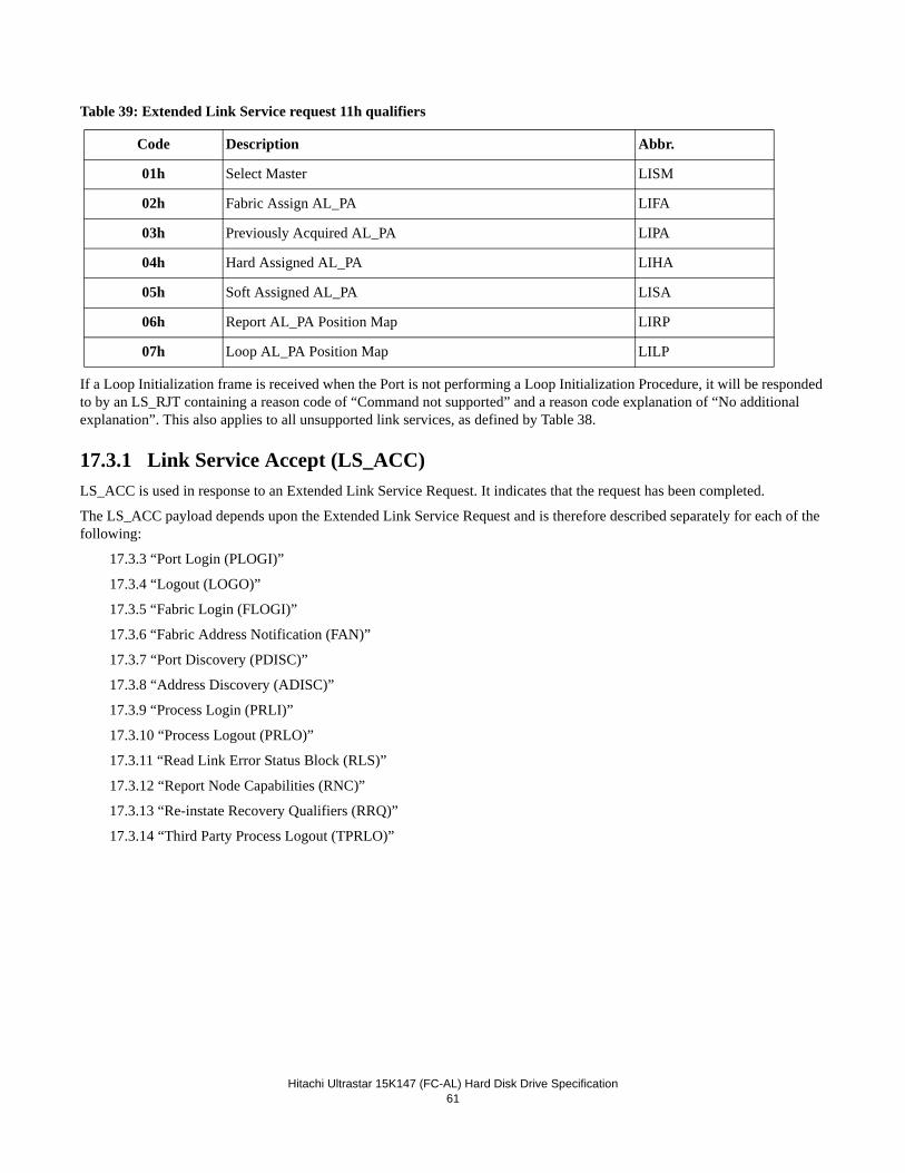
Hitachi Ultrastar 15K147 (FC-AL) Hard Disk Drive Specification61
Table 39: Extended Link Service request 11h qualifiers
If a Loop Initialization frame is received when the Port is not performing a Loop Initialization Procedure, it will be responded to by an LS_RJT containing a reason code of “Command not supported” and a reason code explanation of “No additional explanation”. This also applies to all unsupported link services, as defined by Table 38.
17.3.1 Link Service Accept (LS_ACC)LS_ACC is used in response to an Extended Link Service Request. It indicates that the request has been completed.
The LS_ACC payload depends upon the Extended Link Service Request and is therefore described separately for each of the following:
17.3.3 “Port Login (PLOGI)”
17.3.4 “Logout (LOGO)”
17.3.5 “Fabric Login (FLOGI)”
17.3.6 “Fabric Address Notification (FAN)”
17.3.7 “Port Discovery (PDISC)”
17.3.8 “Address Discovery (ADISC)”
17.3.9 “Process Login (PRLI)”
17.3.10 “Process Logout (PRLO)”
17.3.11 “Read Link Error Status Block (RLS)”
17.3.12 “Report Node Capabilities (RNC)”
17.3.13 “Re-instate Recovery Qualifiers (RRQ)”
17.3.14 “Third Party Process Logout (TPRLO)”
Code Description Abbr.
01h Select Master LISM
02h Fabric Assign AL_PA LIFA
03h Previously Acquired AL_PA LIPA
04h Hard Assigned AL_PA LIHA
05h Soft Assigned AL_PA LISA
06h Report AL_PA Position Map LIRP
07h Loop AL_PA Position Map LILP
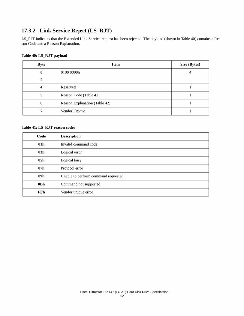
Hitachi Ultratstar 15K147 (FC-AL) Hard Disk Drive Specification62
17.3.2 Link Service Reject (LS_RJT)LS_RJT indicates that the Extended Link Service request has been rejected. The payload (shown in Table 40) contains a Rea-son Code and a Reason Explanation.
Table 40: LS_RJT payload
Table 41: LS_RJT reason codes
Byte Item Size (Bytes)
0
3
0100 0000h 4
4 Reserved 1
5 Reason Code (Table 41) 1
6 Reason Explanation (Table 42) 1
7 Vendor Unique 1
Code Description
01h Invalid command code
03h Logical error
05h Logical busy
07h Protocol error
09h Unable to perform command requested
0Bh Command not supported
FFh Vendor unique error
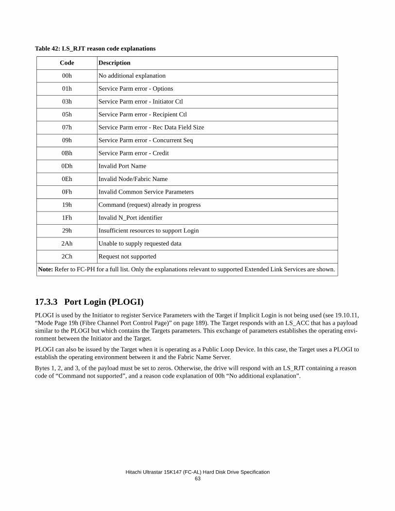
Hitachi Ultrastar 15K147 (FC-AL) Hard Disk Drive Specification63
Table 42: LS_RJT reason code explanations
17.3.3 Port Login (PLOGI)PLOGI is used by the Initiator to register Service Parameters with the Target if Implicit Login is not being used (see 19.10.11, “Mode Page 19h (Fibre Channel Port Control Page)” on page 189). The Target responds with an LS_ACC that has a payload similar to the PLOGI but which contains the Targets parameters. This exchange of parameters establishes the operating envi-ronment between the Initiator and the Target.
PLOGI can also be issued by the Target when it is operating as a Public Loop Device. In this case, the Target uses a PLOGI to establish the operating environment between it and the Fabric Name Server.
Bytes 1, 2, and 3, of the payload must be set to zeros. Otherwise, the drive will respond with an LS_RJT containing a reason code of “Command not supported”, and a reason code explanation of 00h “No additional explanation”.
Code Description
00h No additional explanation
01h Service Parm error - Options
03h Service Parm error - Initiator Ctl
05h Service Parm error - Recipient Ctl
07h Service Parm error - Rec Data Field Size
09h Service Parm error - Concurrent Seq
0Bh Service Parm error - Credit
0Dh Invalid Port Name
0Eh Invalid Node/Fabric Name
0Fh Invalid Common Service Parameters
19h Command (request) already in progress
1Fh Invalid N_Port identifier
29h Insufficient resources to support Login
2Ah Unable to supply requested data
2Ch Request not supported
Note: Refer to FC-PH for a full list. Only the explanations relevant to supported Extended Link Services are shown.
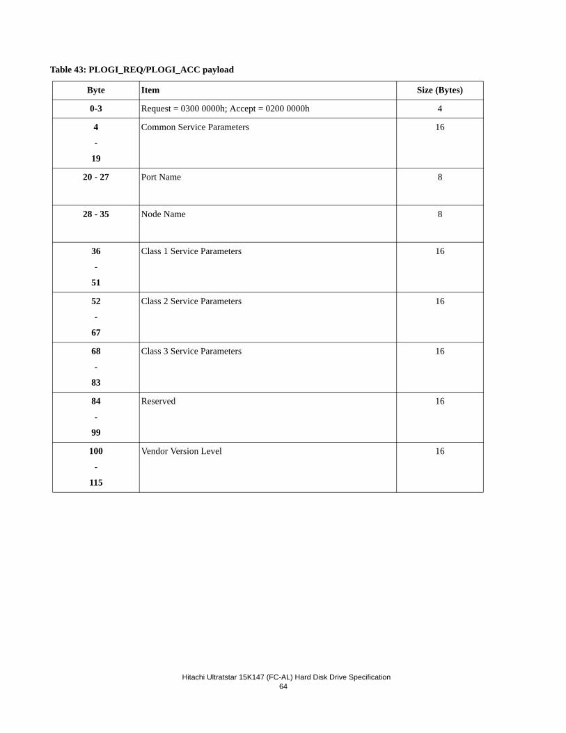
Hitachi Ultratstar 15K147 (FC-AL) Hard Disk Drive Specification64
Table 43: PLOGI_REQ/PLOGI_ACC payload
Byte Item Size (Bytes)
0-3 Request = 0300 0000h; Accept = 0200 0000h 4
4
-
19
Common Service Parameters 16
20 - 27 Port Name 8
28 - 35 Node Name 8
36
-
51
Class 1 Service Parameters 16
52
-
67
Class 2 Service Parameters 16
68
-
83
Class 3 Service Parameters 16
84
-
99
Reserved 16
100
-
115
Vendor Version Level 16
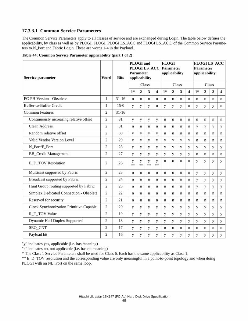
Hitachi Ultrastar 15K147 (FC-AL) Hard Disk Drive Specification65
17.3.3.1 Common Service ParametersThe Common Service Parameters apply to all classes of service and are exchanged during Login. The table below defines the applicability, by class as well as by PLOGI, FLOGI, PLOGI LS_ACC and FLOGI LS_ACC, of the Common Service Parame-ters to N_Port and Fabric Login. These are words 1-4 in the Payload..
Table 44: Common Service Parameter applicability (part 1 of 2)
"y" indicates yes, applicable (i.e. has meaning)"n" indicates no, not applicable (i.e. has no meaning)* The Class 1 Service Parameters shall be used for Class 6. Each has the same applicability as Class 1.** E_D_TOV resolution and the corresponding value are only meaningful in a point-to-point topology and when doing PLOGI with an NL_Port on the same loop.
Service parameter Word Bits
PLOGI andPLOGI LS_ACCParameterapplicability
FLOGI Parameterapplicability
FLOGI LS_ACCParameterapplicability
Class Class Class
1* 2 3 4 1* 2 3 4 1* 2 3 4
FC-PH Version - Obsolete 1 31-16 n n n n n n n n n n n n
Buffer-to-Buffer Credit 1 15-0 y y y n y y y n y y y n
Common Features 2 31-16
Continuously increasing relative offset 2 31 y y y y n n n n n n n n
Clean Address 2 31 n n n n n n n n y y y y
Random relative offset 2 30 y y y y n n n n n n n n
Valid Vendor Version Level 2 29 y y y y y y y y n n n n
N_Port/F_Port 2 28 y y y y y y y y y y y y
BB_Credit Management 2 27 y y y y y y y y n n n n
E_D_TOV Resolution 2 26 y**
y**
y**
y**
n n n n y y y y
Multicast supported by Fabric 2 25 n n n n n n n n y y y y
Broadcast supported by Fabric 2 24 n n n n n n n n y y y y
Hunt Group routing supported by Fabric 2 23 n n n n n n n n y y y y
Simplex Dedicated Connection - Obsolete 2 22 n n n n n n n n n n n n
Reserved for security 2 21 n n n n n n n n n n n n
Clock Synchronization Primitive Capable 2 20 y y y y y y y y y y y y
R_T_TOV Value 2 19 y y y y y y y y y y y y
Dynamic Half Duplex Supported 2 18 y y y y y y y y y y y y
SEQ_CNT 2 17 y y y y n n n n n n n n
Payload bit 2 16 y y y y y y y y y y y y
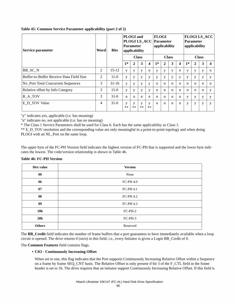
Hitachi Ultratstar 15K147 (FC-AL) Hard Disk Drive Specification66
Table 45: Common Service Parameter applicability (part 2 of 2)
"y" indicates yes, applicable (i.e. has meaning)"n" indicates no, not applicable (i.e. has no meaning)* The Class 1 Service Parameters shall be used for Class 6. Each has the same applicability as Class 1.** E_D_TOV resolution and the corresponding value are only meaningful in a point-to-point topology and when doing PLOGI with an NL_Port on the same loop.
The upper byte of the FC-PH Version field indicates the highest version of FC-PH that is supported and the lower byte indi-cates the lowest. The code/version relationship is shown in Table 46.
Table 46: FC-PH Version
The BB_Credit field indicates the number of frame buffers that a port guarantees to have immediately available when a loop circuit is opened. The drive returns 0 (zero) in this field; i.e., every Initiator is given a Login BB_Credit of 0.
The Common Features field contains flags.
• CIO - Continuously Increasing Offset
When set to one, this flag indicates that the Port supports Continuously Increasing Relative Offset within a Sequence on a frame by frame SEQ_CNT basis. The Relative Offset is only present if bit 3 of the F_CTL field in the frame header is set to 1b. The drive requires that an initiator support Continuously Increasing Relative Offset. If this field is
Service parameter Word Bits
PLOGI andPLOGI LS_ACCParameterapplicability
FLOGI Parameterapplicability
FLOGI LS_ACCParameterapplicability
Class Class Class
1* 2 3 4 1* 2 3 4 1* 2 3 4
BB_SC_N 2 15-12 y y y n y y y n y y y n
Buffer-to-Buffer Receive Data Field Size 2 11-0 y y y y y y y y y y y y
Nx_Port Total Concurrent Sequences 3 31-16 y y y y n n n n n n n n
Relative offset by Info Category 3 15-0 y y y y n n n n n n n y
R_A_TOV 3 31-0 n n n n n n n n y y y y
E_D_TOV Value 4 31-0 y**
y**
y**
y**
n n n n y y y y
Hex value Version
00 None
06 FC-PH 4.0
07 FC-PH 4.1
08 FC-PH 4.2
09 FC-PH 4.3
10h FC-PH-2
20h FC-PH-3
Others Reserved
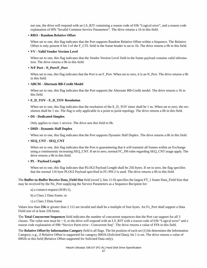
Hitachi Ultrastar 15K147 (FC-AL) Hard Disk Drive Specification67
not one, the drive will respond with an LS_RJT containing a reason code of 03h “Logical error”, and a reason code explanation of 0Fh “Invalid Common Service Parameters”. The drive returns a 1b in this field.
• RRO - Random Relative Offset
When set to one, this flag indicates that the Port supports Random Relative Offset within a Sequence. The Relative Offset is only present if bit 3 of the F_CTL field in the frame header is set to 1b. The drive returns a 0b in this field.
• VV - Valid Vendor Version Level
When set to one, this flag indicates that the Vendor Version Level field in the frame payload contains valid informa-tion. The drive returns a 0b in this field.
• N/F Port - N_Port/F_Port
When set to one, this flag indicates that the Port is an F_Port. When set to zero, it is an N_Port. The drive returns a 0b in this field.
• ABCM - Alternate BB-Credit Model
When set to one, this flag indicates that the Port supports the Alternate BB-Credit model. The drive returns a 1b in this field.
• E_D_TOV - E_D_TOV Resolution
When set to one, this flag indicates that the resolution of the E_D_TOV timer shall be 1 ns. When set to zero, the res-olution shall be 1 ms. The flag is only applicable in a point to point topology. The drive returns a 0b in this field.
• DS - Dedicated Simplex
Only applies to class 1 service. The drive sets this field to 0b.
• DHD - Dynamic Half Duplex
When set to one, this flag indicates that the Port supports Dynamic Half Duplex. The drive returns a 0b in this field.
• SEQ_CNT - SEQ_CNT
When set to one, this flag indicates that the Port is guaranteeing that it will transmit all frames within an Exchange using a continuously increasing SEQ_CNT. If set to zero, normal FC_PH rules regarding SEQ_CNT usage apply. The drive returns a 0b in this field.
• PL - Payload Length
When set to one, this flag indicates that PLOGI Payload Length shall be 256 bytes. If set to zero, the flag specifies that the normal 116 byte PLOGI Payload specified in FC-PH-2 is used. The drive returns a 0b in this field.
The Buffer-to-Buffer Receive Data_Field Size field (word 2, bits 11-0) specifies the largest FT_1 frame Data_Field Size that may be received by the Nx_Port supplying the Service Parameters as a Sequence Recipient for:
a) a connect-request (SOFc1),
b) a Class 2 Data frame, or
c) a Class 3 Data frame
Values less than 256 or greater than 2 112 are invalid and shall be a multiple of four bytes. An Fx_Port shall support a Data Field size of at least 256 bytes.
The Total Concurrent Sequences field indicates the number of concurrent sequences that the Port can support for all 3 classes. The value sent must be > 0, or the drive will respond with an LS_RJT with a reason code of 03h “Logical error” and a reason code explanation of 09h “Service Parm error - Concurrent Seq”. The drive returns a value of FFh in this field.
The Relative Offset by Information Category field is all flags. The bit position of each set (1) bit determines the Information Category; e.g., if Relative Offset is supported for category 0001b (Solicited Data), bit 1 is set. The drive returns a value of 0002h in this field (Relative Offset supported for Solicited Data only).
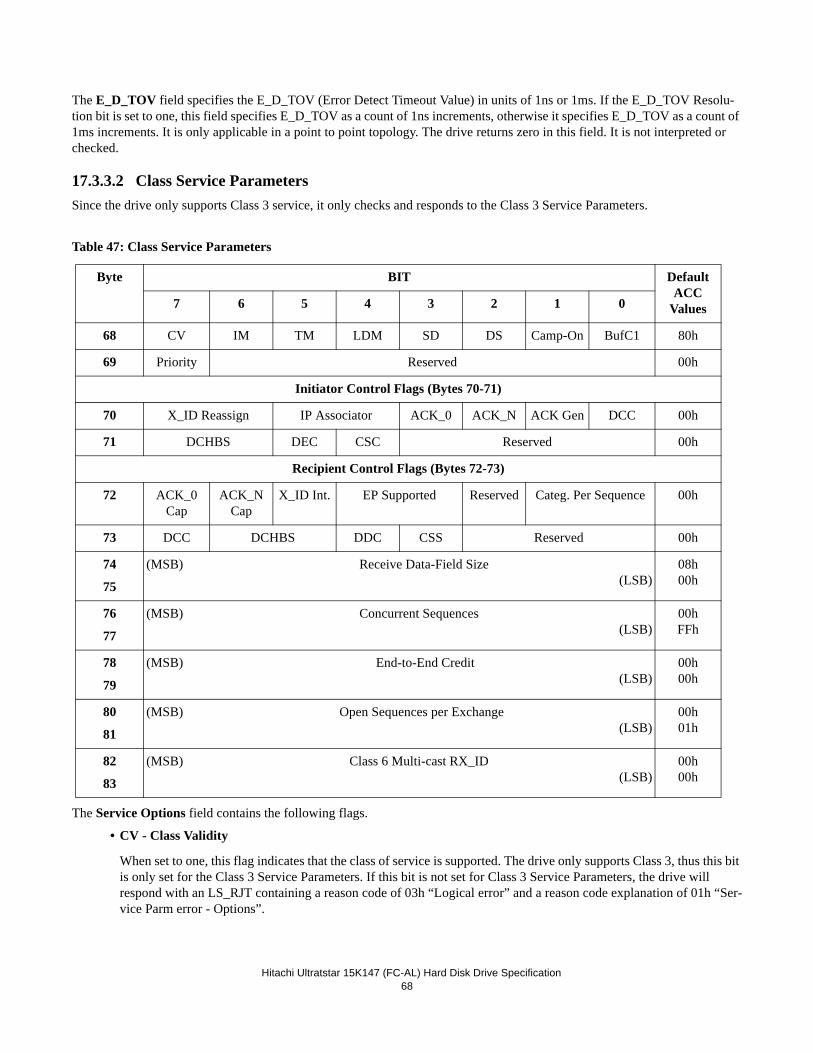
Hitachi Ultratstar 15K147 (FC-AL) Hard Disk Drive Specification68
The E_D_TOV field specifies the E_D_TOV (Error Detect Timeout Value) in units of 1ns or 1ms. If the E_D_TOV Resolu-tion bit is set to one, this field specifies E_D_TOV as a count of 1ns increments, otherwise it specifies E_D_TOV as a count of 1ms increments. It is only applicable in a point to point topology. The drive returns zero in this field. It is not interpreted or checked.
17.3.3.2 Class Service ParametersSince the drive only supports Class 3 service, it only checks and responds to the Class 3 Service Parameters.
Table 47: Class Service Parameters
The Service Options field contains the following flags.
• CV - Class Validity
When set to one, this flag indicates that the class of service is supported. The drive only supports Class 3, thus this bit is only set for the Class 3 Service Parameters. If this bit is not set for Class 3 Service Parameters, the drive will respond with an LS_RJT containing a reason code of 03h “Logical error” and a reason code explanation of 01h “Ser-vice Parm error - Options”.
Byte BIT DefaultACC
Values7 6 5 4 3 2 1 0
68 CV IM TM LDM SD DS Camp-On BufC1 80h
69 Priority Reserved 00h
Initiator Control Flags (Bytes 70-71)
70 X_ID Reassign IP Associator ACK_0 ACK_N ACK Gen DCC 00h
71 DCHBS DEC CSC Reserved 00h
Recipient Control Flags (Bytes 72-73)
72 ACK_0 Cap
ACK_N Cap
X_ID Int. EP Supported Reserved Categ. Per Sequence 00h
73 DCC DCHBS DDC CSS Reserved 00h
74
75
(MSB) Receive Data-Field Size(LSB)
08h00h
76
77
(MSB) Concurrent Sequences(LSB)
00hFFh
78
79
(MSB) End-to-End Credit(LSB)
00h00h
80
81
(MSB) Open Sequences per Exchange(LSB)
00h01h
82
83
(MSB) Class 6 Multi-cast RX_ID(LSB)
00h00h
Hitachi Ultrastar 15K147 (FC-AL) Hard Disk Drive Specification69
• IM - Intermix Mode
The flag only applies to class 1 service and is reserved for classes 2 and 3. The drive returns 0b in this field.
• TM - Transparent Mode
The flag does not apply to PLOGI. The drive returns 0b in this field.
• LDM - Lock Down Mode
This flag does not apply to PLOGI. The drive returns 0b in this field.
• SD - Sequential Delivery
This flag does not apply to PLOGI. The drive returns 0b in this field.
• DS - Dedicated Simplex
This flag only applies to class 1 service. The drive returns 0b in this field.
• Camp-On - Camp-On
This flag only applies to class 1 service. The drive returns 0b in this field.
• BufC1 - Buffered Class 1
This flag only applies to class 1 service. The drive returns 0b in this field.
• Priority
This flag does not apply to class 3 service. The drive returns 0b in this field.
The Initiator Control flags specify which protocols, policies, or functions the supplier of the Service Parameters requests of the recipient or is capable of.
• X_ID Reassign - X_ID Reassignment
0 0 X_ID Reassignment not supported.
0 1 X_ID Reassignment supported.
1 0 Reserved.
1 1 X_ID Reassignment required.
The X_ID Reassignment bits only apply to class 1 or 2 and therefore are not checked by the drive.
• IP Associator - Initial Process Associator
0 0 Initial Process Associator not supported.
0 1 Initial Process Associator supported.
1 0 Reserved.
1 1 Initial Process Associator required.
The drive accepts values of “00” and “01” in this field. If other values are sent, the drive responds with an LS_RJT containing a reason code of 03h “Logical error” and a reason code explanation of 03h “Service Parm error - Initiator Ctl”. The drive returns 00b in this field.
• ACK_0 - ACK_0 Capability
This flag does not apply to class 3 and therefore is not checked by the drive. The drive returns 0b in this field.
• ACK_N - ACK_N Capability
This flag does not apply to class 3 and therefore is not checked by the drive. The drive returns 0b in this field.
• ACK Gen - ACK generation assistance
This flag does not apply to class 3 and therefore is not checked by the drive. The drive returns 0b in this field.
Hitachi Ultratstar 15K147 (FC-AL) Hard Disk Drive Specification70
• DCC - Data compression capable
When set to one, this flag indicates the Port supports data compression as a Sequence Initiator. The drive does not support data compression, therefore the drive returns 0b in this field.
• DCHBS - Data compression History buffer size
This field indicates the History buffer size supported by the Port as a Sequence Initiator. The drive does not support data compression, therefore, the drive returns 00b in this field.
• DEC - Data encryption capable
When set to one, this flag indicates the Port supports data encryption as a Sequence Initiator. The drive does not sup-port data compression, therefore the drive returns 0b in this field.
• CSC - Clock synchronization capable
When set to one, this flag indicates the Port is capable of performing clock synchronization as a Sequence Initiator (Clock Synchronization Server). The drive is not capable of performing clock synchronization, therefore the drive returns 0b in this field.
The Recipient Control flags specify which functions the supplier of the Service Parameters supports when receiving frames.
• ACK_0 Cap - ACK_0 Capability
This flag only applies to class 1 or 2, therefore is not checked by the drive. The drive returns 0b in this field.
• ACK_N Cap - ACK_N Capability
This flag only applies to class 1 or 2, therefore is not checked by the drive. The drive returns 0b in this field.
• X_ID Int. - X_ID Interlock
This flag only applies to class 1 or 2, therefore is not checked by the drive. The drive returns 0b in this field.
• EPS - Error Policy Supported 0 0 Only discard supported 0 1 Reserved 1 0 Both discard and process supported 1 1 Reserved
The Error Policy bits are not checked by the drive. The drive returns 00b in this field.
• Categ. per Sequence - Categories per Sequence 0 0 1 Category/Sequence 0 1 2 Categories/Sequence 1 0 Reserved 1 1 More than 2 Categories/Sequence. The drive returns 00b in this field.
The Receive Data Field size is the largest payload (in bytes) that the Port is capable of receiving. It must be less than or equal to the Buffer to Buffer Receive Data Field specified in the Common Service Parameters. Sizes less than 128, greater than 2112, or not divisible by 4 are invalid, in which case the drive will respond with an LS_RJT containing a reason code of 03h “Logical error” and a reason code explanation of 07h “Service Parm error - Rec Data Field Size”. The drive returns 2048 in this field.
The Concurrent Sequences field specifies the number of separate Sequences that the drive is capable of tracking. The value sent must be > 0, or the drive will respond with an LS_RJT containing a reason code of 03h “Logical error” and a reason code explanation of 09h “Service Parm error - Concurrent Seq”. The drive returns a value of 255 in this field.
The End-to-end Credit field applies only to classes 1 and 2 and is therefore not checked by the drive. The drive returns 0 in this field.
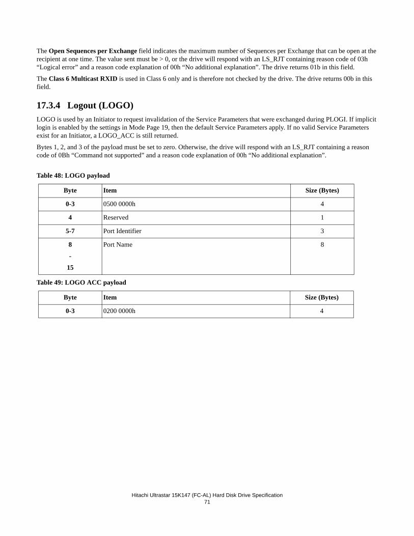
Hitachi Ultrastar 15K147 (FC-AL) Hard Disk Drive Specification71
The Open Sequences per Exchange field indicates the maximum number of Sequences per Exchange that can be open at the recipient at one time. The value sent must be > 0, or the drive will respond with an LS_RJT containing reason code of 03h “Logical error” and a reason code explanation of 00h “No additional explanation”. The drive returns 01b in this field.
The Class 6 Multicast RXID is used in Class 6 only and is therefore not checked by the drive. The drive returns 00b in this field.
17.3.4 Logout (LOGO)LOGO is used by an Initiator to request invalidation of the Service Parameters that were exchanged during PLOGI. If implicit login is enabled by the settings in Mode Page 19, then the default Service Parameters apply. If no valid Service Parameters exist for an Initiator, a LOGO_ACC is still returned.
Bytes 1, 2, and 3 of the payload must be set to zero. Otherwise, the drive will respond with an LS_RJT containing a reason code of 0Bh “Command not supported” and a reason code explanation of 00h “No additional explanation”.
Table 48: LOGO payload
Table 49: LOGO ACC payload
Byte Item Size (Bytes)
0-3 0500 0000h 4
4 Reserved 1
5-7 Port Identifier 3
8
-
15
Port Name 8
Byte Item Size (Bytes)
0-3 0200 0000h 4
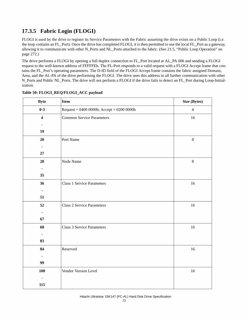
Hitachi Ultratstar 15K147 (FC-AL) Hard Disk Drive Specification72
17.3.5 Fabric Login (FLOGI)FLOGI is used by the drive to register its Service Parameters with the Fabric assuming the drive exists on a Public Loop (i.e. the loop contains an FL_Port). Once the drive has completed FLOGI, it is then permitted to use the local FL_Port as a gateway, allowing it to communicate with other N_Ports and NL_Ports attached to the fabric. (See 21.5, “Public Loop Operation” on page 272.)
The drive performs a FLOGI by opening a full duplex connection to FL_Port located at AL_PA 00h and sending a FLOGI request to the well-known address of FFFFFEh. The FL-Port responds to a valid request with a FLOGI Accept frame that con-tains the FL_Port’s operating parameters. The D-ID field of the FLOGI Accept frame contains the fabric assigned Domain, Area, and the AL-PA of the drive performing the FLOGI. The drive uses this address in all further communication with other N_Ports and Public NL_Ports. The drive will not perform a FLOGI if the drive fails to detect an FL_Port during Loop-Initial-ization.
Table 50: FLOGI_REQ/FLOGI_ACC payload
Byte Item Size (Bytes)
0-3 Request = 0400 0000h; Accept = 0200 0000h 4
4
-
19
Common Service Parameters 16
20
-
27
Port Name 8
28
-
35
Node Name 8
36
-
51
Class 1 Service Parameters 16
52
-
67
Class 2 Service Parameters 16
68
-
83
Class 3 Service Parameters 16
84
-
99
Reserved 16
100
-
115
Vendor Version Level 16
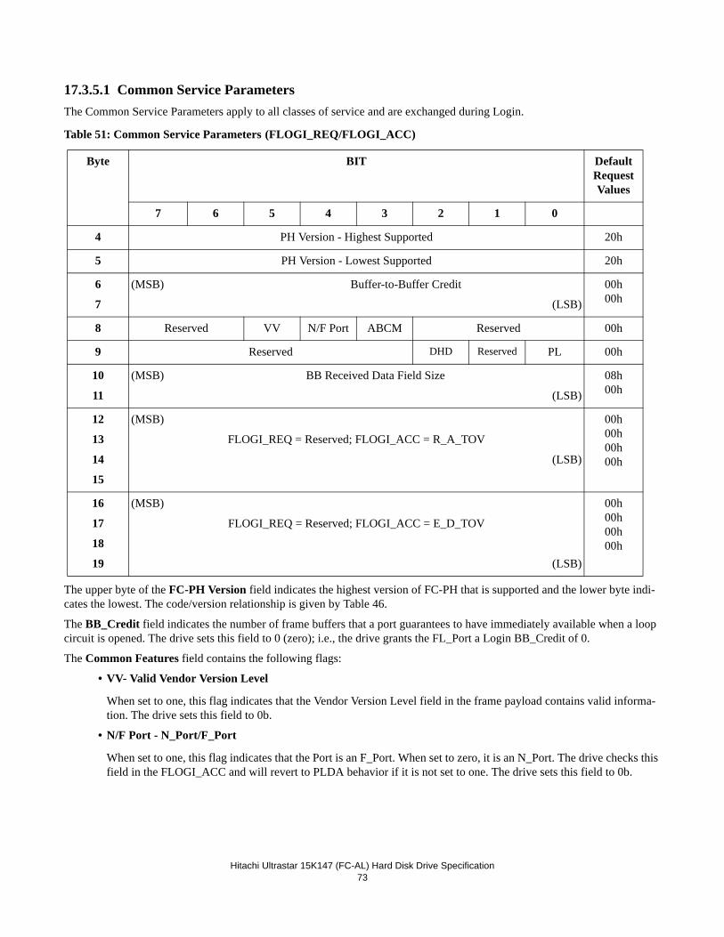
Hitachi Ultrastar 15K147 (FC-AL) Hard Disk Drive Specification73
17.3.5.1 Common Service ParametersThe Common Service Parameters apply to all classes of service and are exchanged during Login.
Table 51: Common Service Parameters (FLOGI_REQ/FLOGI_ACC)
The upper byte of the FC-PH Version field indicates the highest version of FC-PH that is supported and the lower byte indi-cates the lowest. The code/version relationship is given by Table 46.
The BB_Credit field indicates the number of frame buffers that a port guarantees to have immediately available when a loop circuit is opened. The drive sets this field to 0 (zero); i.e., the drive grants the FL_Port a Login BB_Credit of 0.
The Common Features field contains the following flags:
• VV- Valid Vendor Version Level
When set to one, this flag indicates that the Vendor Version Level field in the frame payload contains valid informa-tion. The drive sets this field to 0b.
• N/F Port - N_Port/F_Port
When set to one, this flag indicates that the Port is an F_Port. When set to zero, it is an N_Port. The drive checks this field in the FLOGI_ACC and will revert to PLDA behavior if it is not set to one. The drive sets this field to 0b.
Byte BIT DefaultRequest Values
7 6 5 4 3 2 1 0
4 PH Version - Highest Supported 20h
5 PH Version - Lowest Supported 20h
6
7
(MSB) Buffer-to-Buffer Credit
(LSB)
00h00h
8 Reserved VV N/F Port ABCM Reserved 00h
9 Reserved DHD Reserved PL 00h
10
11
(MSB) BB Received Data Field Size
(LSB)
08h00h
12
13
14
15
(MSB)
FLOGI_REQ = Reserved; FLOGI_ACC = R_A_TOV
(LSB)
00h00h00h00h
16
17
18
19
(MSB)
FLOGI_REQ = Reserved; FLOGI_ACC = E_D_TOV
(LSB)
00h00h00h00h
Hitachi Ultratstar 15K147 (FC-AL) Hard Disk Drive Specification74
• ABCM - Alternate BB-Credit model
When set to one, this flag indicates that the Port supports the Alternate BB-Credit model. As per the FC-AL Specifi-cation, an L_Port and must support the Alternate BB-Credit model. The drive checks the value returned by the FL_Port and will revert to PLDA behavior if it is not set to one. The drive sets this field to 1b.
• DHD - Dynamic Half Duplex
When set to one, this flag indicates that the Port supports the Dynamic Half Duplex. The drive sets this field to 0b.
• PL - Payload Length
When set to one, this flag indicates that FLOGI Payload Length shall be 256 bytes. If set to zero, the flag specifies that the normal 116 byte FLOGI payload specified in FC-PH-2. The drive sets this field to 0b.
The Buffer to Buffer Receive Data Field size indicates the largest frame payload (in bytes) that the Port can receive. Sizes less than 128, greater than 2112, or not divisible by 4 are invalid. The drive check this field in the FLOGI_ACC payload and will revert to PLDA behavior if an invalid value is returned. The drive sets this field to 2048.
The R_A_TOV field specifies the R_A_TOV (Resource Allocation Timeout Value) supplied by the fabric in units of 1ms. The fabric port sets this field in its FLOGI_ACC payload. This field is reserved in the FLOGI_REQ and the drive therefore sets this field to zero. After FLOGI is complete, the drive will use this value for R_A_TOV until the drive is reset, reverts to PLDA behavior, or performs another FLOGI.
The E_D_TOV field specifies the E_D_TOV (Error Detect Timeout Value) supplied by the fabric in units of 1ns or 1ms. The fabric port sets this field in its FLOGI_ACC payload. This field is reserved in the FLOGI_REQ and the drive therefore sets this field to zero. After FLOGI is complete, the drive will use this value for E_D_TOV until the drive is reset, reverts to PLDA behavior, or performs another FLOGI.
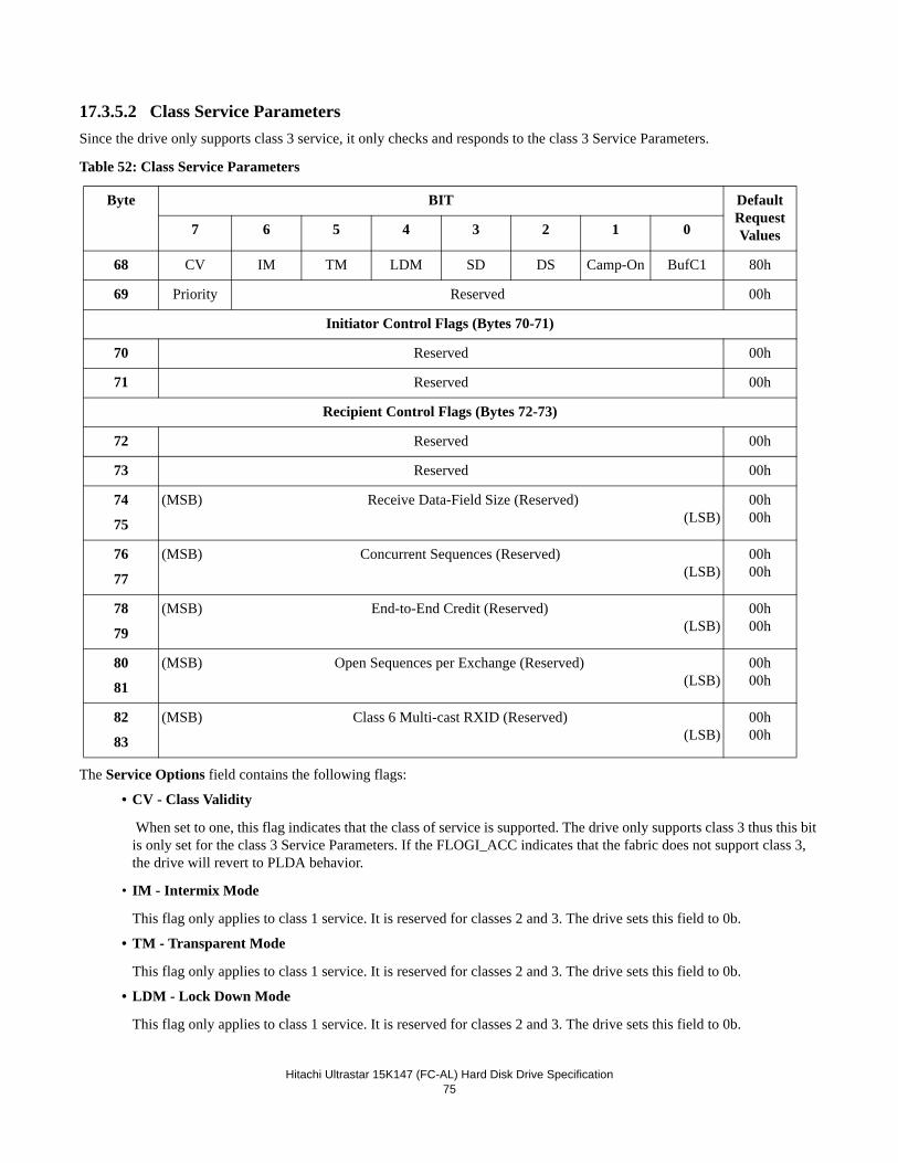
Hitachi Ultrastar 15K147 (FC-AL) Hard Disk Drive Specification75
17.3.5.2 Class Service ParametersSince the drive only supports class 3 service, it only checks and responds to the class 3 Service Parameters.
Table 52: Class Service Parameters
The Service Options field contains the following flags:
• CV - Class Validity
When set to one, this flag indicates that the class of service is supported. The drive only supports class 3 thus this bit is only set for the class 3 Service Parameters. If the FLOGI_ACC indicates that the fabric does not support class 3, the drive will revert to PLDA behavior.
• IM - Intermix Mode
This flag only applies to class 1 service. It is reserved for classes 2 and 3. The drive sets this field to 0b.
• TM - Transparent Mode
This flag only applies to class 1 service. It is reserved for classes 2 and 3. The drive sets this field to 0b.
• LDM - Lock Down Mode
This flag only applies to class 1 service. It is reserved for classes 2 and 3. The drive sets this field to 0b.
Byte BIT DefaultRequest Values7 6 5 4 3 2 1 0
68 CV IM TM LDM SD DS Camp-On BufC1 80h
69 Priority Reserved 00h
Initiator Control Flags (Bytes 70-71)
70 Reserved 00h
71 Reserved 00h
Recipient Control Flags (Bytes 72-73)
72 Reserved 00h
73 Reserved 00h
74
75
(MSB) Receive Data-Field Size (Reserved)(LSB)
00h00h
76
77
(MSB) Concurrent Sequences (Reserved)(LSB)
00h00h
78
79
(MSB) End-to-End Credit (Reserved)(LSB)
00h00h
80
81
(MSB) Open Sequences per Exchange (Reserved)(LSB)
00h00h
82
83
(MSB) Class 6 Multi-cast RXID (Reserved)(LSB)
00h00h
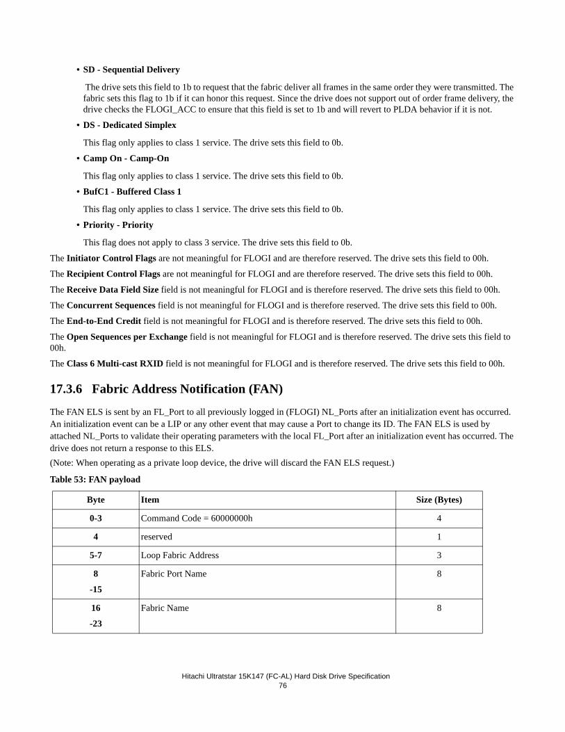
Hitachi Ultratstar 15K147 (FC-AL) Hard Disk Drive Specification76
• SD - Sequential Delivery
The drive sets this field to 1b to request that the fabric deliver all frames in the same order they were transmitted. The fabric sets this flag to 1b if it can honor this request. Since the drive does not support out of order frame delivery, the drive checks the FLOGI_ACC to ensure that this field is set to 1b and will revert to PLDA behavior if it is not.
• DS - Dedicated Simplex
This flag only applies to class 1 service. The drive sets this field to 0b.
• Camp On - Camp-On
This flag only applies to class 1 service. The drive sets this field to 0b.
• BufC1 - Buffered Class 1
This flag only applies to class 1 service. The drive sets this field to 0b.
• Priority - Priority
This flag does not apply to class 3 service. The drive sets this field to 0b.
The Initiator Control Flags are not meaningful for FLOGI and are therefore reserved. The drive sets this field to 00h.
The Recipient Control Flags are not meaningful for FLOGI and are therefore reserved. The drive sets this field to 00h.
The Receive Data Field Size field is not meaningful for FLOGI and is therefore reserved. The drive sets this field to 00h.
The Concurrent Sequences field is not meaningful for FLOGI and is therefore reserved. The drive sets this field to 00h.
The End-to-End Credit field is not meaningful for FLOGI and is therefore reserved. The drive sets this field to 00h.
The Open Sequences per Exchange field is not meaningful for FLOGI and is therefore reserved. The drive sets this field to 00h.
The Class 6 Multi-cast RXID field is not meaningful for FLOGI and is therefore reserved. The drive sets this field to 00h.
17.3.6 Fabric Address Notification (FAN)
The FAN ELS is sent by an FL_Port to all previously logged in (FLOGI) NL_Ports after an initialization event has occurred. An initialization event can be a LIP or any other event that may cause a Port to change its ID. The FAN ELS is used by attached NL_Ports to validate their operating parameters with the local FL_Port after an initialization event has occurred. The drive does not return a response to this ELS.(Note: When operating as a private loop device, the drive will discard the FAN ELS request.)
Table 53: FAN payload
Byte Item Size (Bytes)
0-3 Command Code = 60000000h 4
4 reserved 1
5-7 Loop Fabric Address 3
8
-15
Fabric Port Name 8
16
-23
Fabric Name 8
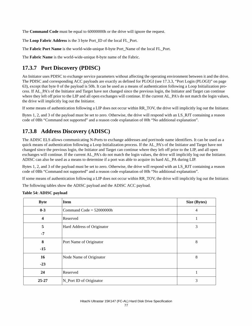
Hitachi Ultrastar 15K147 (FC-AL) Hard Disk Drive Specification77
The Command Code must be equal to 60000000h or the drive will ignore the request.
The Loop Fabric Address is the 3 byte Port_ID of the local FL_Port.
The Fabric Port Name is the world-wide-unique 8-byte Port_Name of the local FL_Port.
The Fabric Name is the world-wide-unique 8-byte name of the Fabric.
17.3.7 Port Discovery (PDISC)An Initiator uses PDISC to exchange service parameters without affecting the operating environment between it and the drive. The PDISC and corresponding ACC payloads are exactly as defined for PLOGI (see 17.3.3, “Port Login (PLOGI)” on page 63), except that byte 0 of the payload is 50h. It can be used as a means of authentication following a Loop Initialization pro-cess. If AL_PA's of the Initiator and Target have not changed since the previous login, the Initiator and Target can continue where they left off prior to the LIP and all open exchanges will continue. If the current AL_PA's do not match the login values, the drive will implicitly log out the Initiator.
If some means of authentication following a LIP does not occur within RR_TOV, the drive will implicitly log out the Initiator.
Bytes 1, 2, and 3 of the payload must be set to zero. Otherwise, the drive will respond with an LS_RJT containing a reason code of 0Bh “Command not supported” and a reason code explanation of 00h “No additional explanation”.
17.3.8 Address Discovery (ADISC)The ADISC ELS allows communicating N-Ports to exchange addresses and port/node name identifiers. It can be used as a quick means of authentication following a Loop Initialization process. If the AL_PA's of the Initiator and Target have not changed since the previous login, the Initiator and Target can continue where they left off prior to the LIP, and all open exchanges will continue. If the current AL_PA's do not match the login values, the drive will implicitly log out the Initiator. ADISC can also be used as a means to determine if a port was able to acquire its hard AL_PA during LIP.
Bytes 1, 2, and 3 of the payload must be set to zero. Otherwise, the drive will respond with an LS_RJT containing a reason code of 0Bh “Command not supported” and a reason code explanation of 00h “No additional explanation”.
If some means of authentication following a LIP does not occur within RR_TOV, the drive will implicitly log out the Initiator.
The following tables show the ADISC payload and the ADISC ACC payload.
Table 54: ADISC payload
Byte Item Size (Bytes)
0-3 Command Code = 52000000h 4
4 Reserved 1
5
-7
Hard Address of Originator 3
8
-15
Port Name of Originator 8
16
-23
Node Name of Originator 8
24 Reserved 1
25-27 N_Port ID of Originator 3
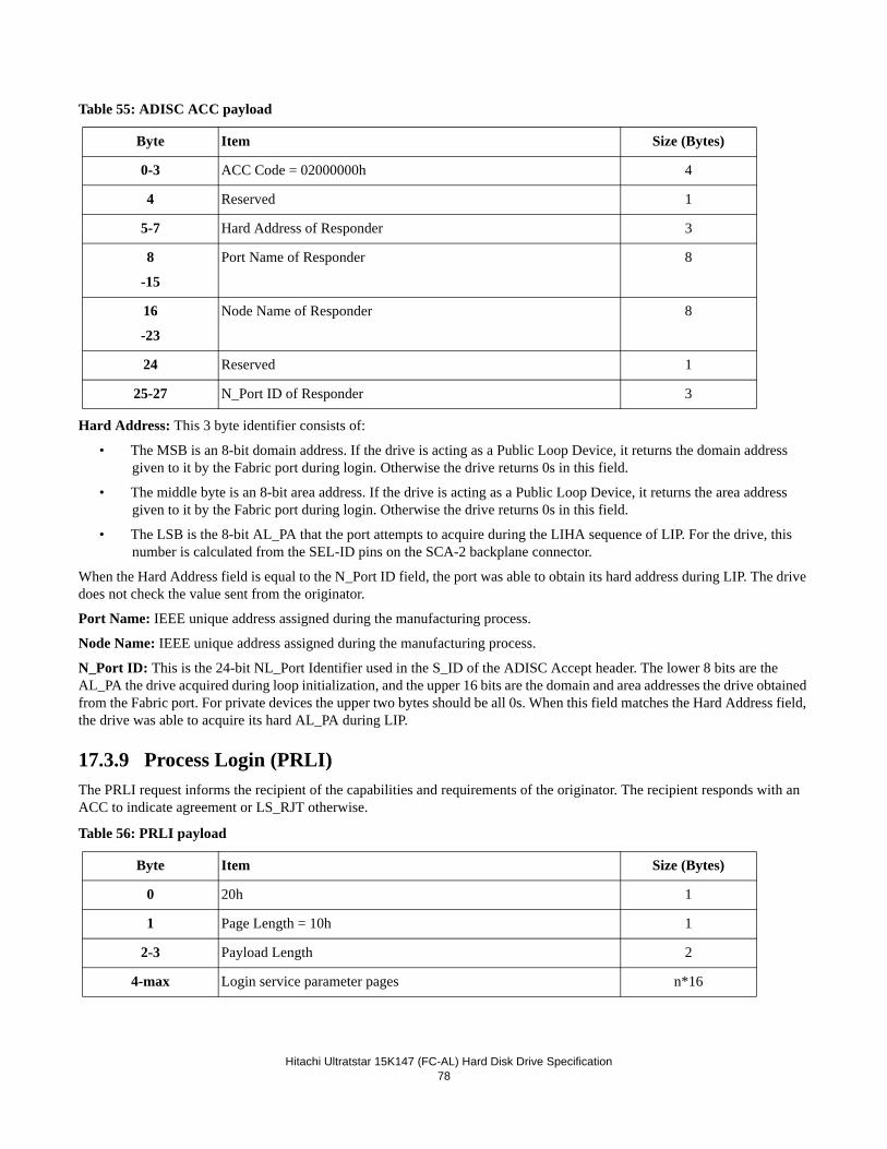
Hitachi Ultratstar 15K147 (FC-AL) Hard Disk Drive Specification78
Table 55: ADISC ACC payload
Hard Address: This 3 byte identifier consists of:
• The MSB is an 8-bit domain address. If the drive is acting as a Public Loop Device, it returns the domain address given to it by the Fabric port during login. Otherwise the drive returns 0s in this field.
• The middle byte is an 8-bit area address. If the drive is acting as a Public Loop Device, it returns the area address given to it by the Fabric port during login. Otherwise the drive returns 0s in this field.
• The LSB is the 8-bit AL_PA that the port attempts to acquire during the LIHA sequence of LIP. For the drive, this number is calculated from the SEL-ID pins on the SCA-2 backplane connector.
When the Hard Address field is equal to the N_Port ID field, the port was able to obtain its hard address during LIP. The drive does not check the value sent from the originator.
Port Name: IEEE unique address assigned during the manufacturing process.
Node Name: IEEE unique address assigned during the manufacturing process.
N_Port ID: This is the 24-bit NL_Port Identifier used in the S_ID of the ADISC Accept header. The lower 8 bits are the AL_PA the drive acquired during loop initialization, and the upper 16 bits are the domain and area addresses the drive obtained from the Fabric port. For private devices the upper two bytes should be all 0s. When this field matches the Hard Address field, the drive was able to acquire its hard AL_PA during LIP.
17.3.9 Process Login (PRLI)The PRLI request informs the recipient of the capabilities and requirements of the originator. The recipient responds with an ACC to indicate agreement or LS_RJT otherwise.
Table 56: PRLI payload
Byte Item Size (Bytes)
0-3 ACC Code = 02000000h 4
4 Reserved 1
5-7 Hard Address of Responder 3
8
-15
Port Name of Responder 8
16
-23
Node Name of Responder 8
24 Reserved 1
25-27 N_Port ID of Responder 3
Byte Item Size (Bytes)
0 20h 1
1 Page Length = 10h 1
2-3 Payload Length 2
4-max Login service parameter pages n*16
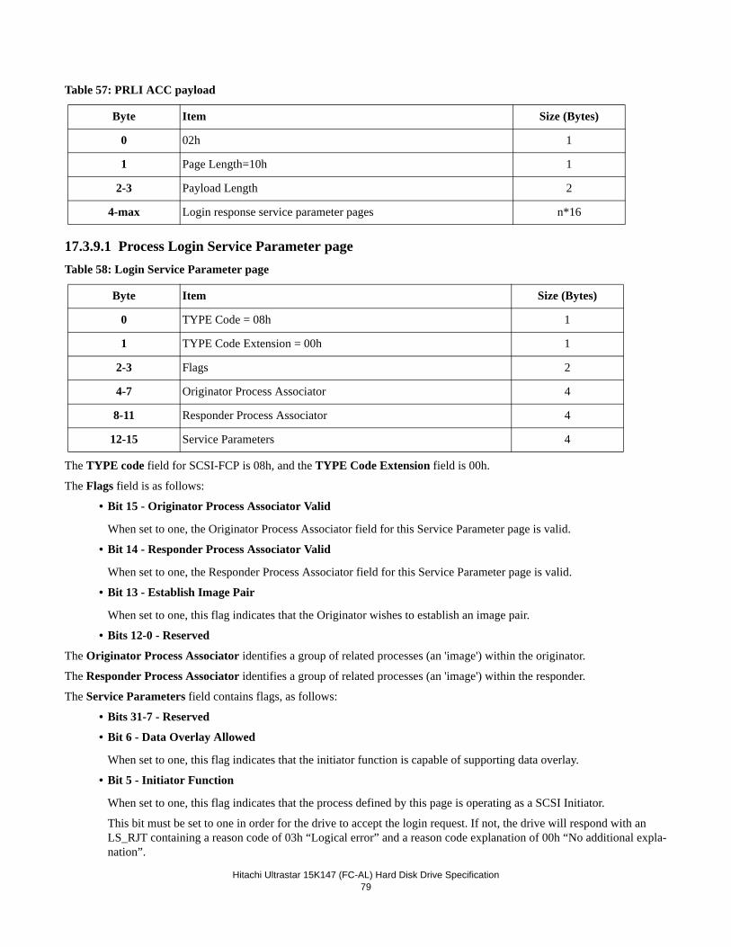
Hitachi Ultrastar 15K147 (FC-AL) Hard Disk Drive Specification79
Table 57: PRLI ACC payload
17.3.9.1 Process Login Service Parameter pageTable 58: Login Service Parameter page
The TYPE code field for SCSI-FCP is 08h, and the TYPE Code Extension field is 00h.
The Flags field is as follows:
• Bit 15 - Originator Process Associator Valid
When set to one, the Originator Process Associator field for this Service Parameter page is valid.
• Bit 14 - Responder Process Associator Valid
When set to one, the Responder Process Associator field for this Service Parameter page is valid.
• Bit 13 - Establish Image Pair
When set to one, this flag indicates that the Originator wishes to establish an image pair.
• Bits 12-0 - Reserved
The Originator Process Associator identifies a group of related processes (an 'image') within the originator.
The Responder Process Associator identifies a group of related processes (an 'image') within the responder.
The Service Parameters field contains flags, as follows:
• Bits 31-7 - Reserved
• Bit 6 - Data Overlay Allowed
When set to one, this flag indicates that the initiator function is capable of supporting data overlay.
• Bit 5 - Initiator Function
When set to one, this flag indicates that the process defined by this page is operating as a SCSI Initiator.
This bit must be set to one in order for the drive to accept the login request. If not, the drive will respond with an LS_RJT containing a reason code of 03h “Logical error” and a reason code explanation of 00h “No additional expla-nation”.
Byte Item Size (Bytes)
0 02h 1
1 Page Length=10h 1
2-3 Payload Length 2
4-max Login response service parameter pages n*16
Byte Item Size (Bytes)
0 TYPE Code = 08h 1
1 TYPE Code Extension = 00h 1
2-3 Flags 2
4-7 Originator Process Associator 4
8-11 Responder Process Associator 4
12-15 Service Parameters 4
Hitachi Ultratstar 15K147 (FC-AL) Hard Disk Drive Specification80
• Bit 4 - Target Function
When set to one, this flag indicates that the process defined by this page is operating as a SCSI Target.
• Bit 3 - Command/Data Mixed Allowed
When set to one, this flag indicates that FCP_CMND and FCP_DATA may be combined in one IU.
• Bit 2 - Data/Response Mixed Allowed
When set to one, this flag indicates that FCP_DATA and FCP_RSP may be combined in one IU.
• Bit 1 - Read XFER_RDY Disabled
When set to one, this flag indicates that the FCP_XFER_RDY IU may not be used for SCSI READ operations.
• Bit 0 - Write XFER_RDY Disabled
When set to one, this flag indicates that the FCP_XFER_RDY IU may not be used for SCSI WRITE operations.
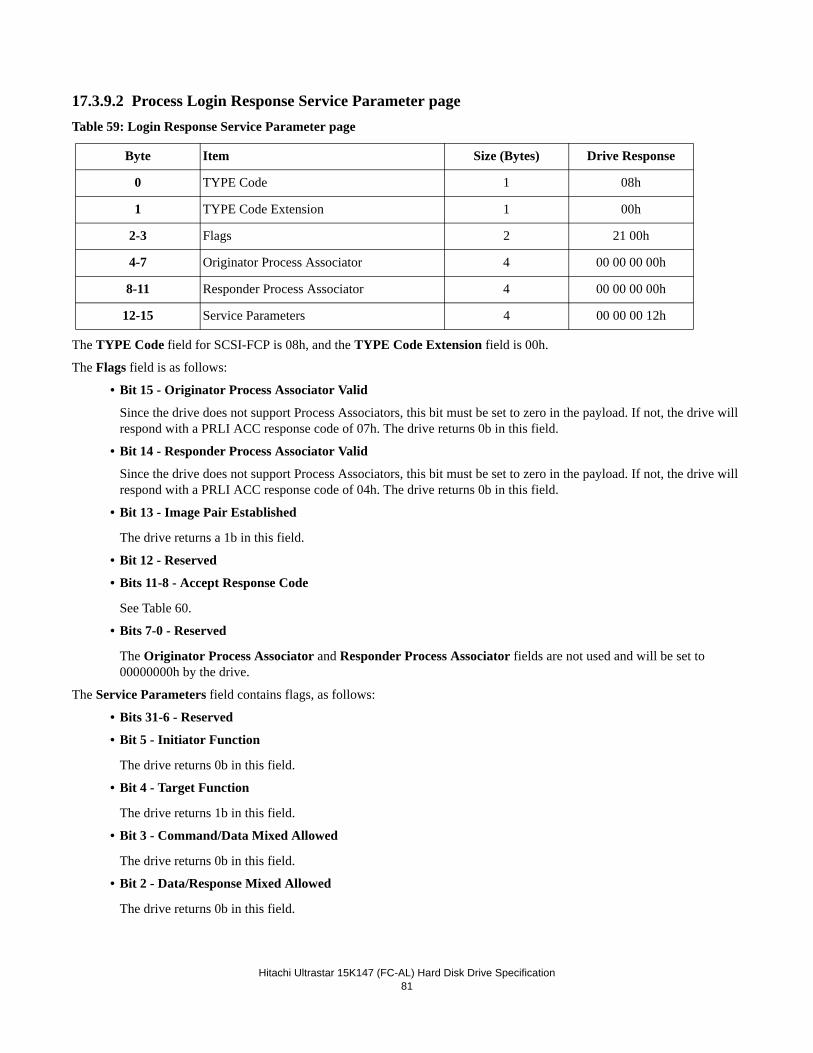
Hitachi Ultrastar 15K147 (FC-AL) Hard Disk Drive Specification81
17.3.9.2 Process Login Response Service Parameter pageTable 59: Login Response Service Parameter page
The TYPE Code field for SCSI-FCP is 08h, and the TYPE Code Extension field is 00h.
The Flags field is as follows:
• Bit 15 - Originator Process Associator Valid
Since the drive does not support Process Associators, this bit must be set to zero in the payload. If not, the drive will respond with a PRLI ACC response code of 07h. The drive returns 0b in this field.
• Bit 14 - Responder Process Associator Valid
Since the drive does not support Process Associators, this bit must be set to zero in the payload. If not, the drive will respond with a PRLI ACC response code of 04h. The drive returns 0b in this field.
• Bit 13 - Image Pair Established
The drive returns a 1b in this field.
• Bit 12 - Reserved
• Bits 11-8 - Accept Response Code
See Table 60.
• Bits 7-0 - Reserved
The Originator Process Associator and Responder Process Associator fields are not used and will be set to 00000000h by the drive.
The Service Parameters field contains flags, as follows:
• Bits 31-6 - Reserved
• Bit 5 - Initiator Function
The drive returns 0b in this field.
• Bit 4 - Target Function
The drive returns 1b in this field.
• Bit 3 - Command/Data Mixed Allowed
The drive returns 0b in this field.
• Bit 2 - Data/Response Mixed Allowed
The drive returns 0b in this field.
Byte Item Size (Bytes) Drive Response
0 TYPE Code 1 08h
1 TYPE Code Extension 1 00h
2-3 Flags 2 21 00h
4-7 Originator Process Associator 4 00 00 00 00h
8-11 Responder Process Associator 4 00 00 00 00h
12-15 Service Parameters 4 00 00 00 12h
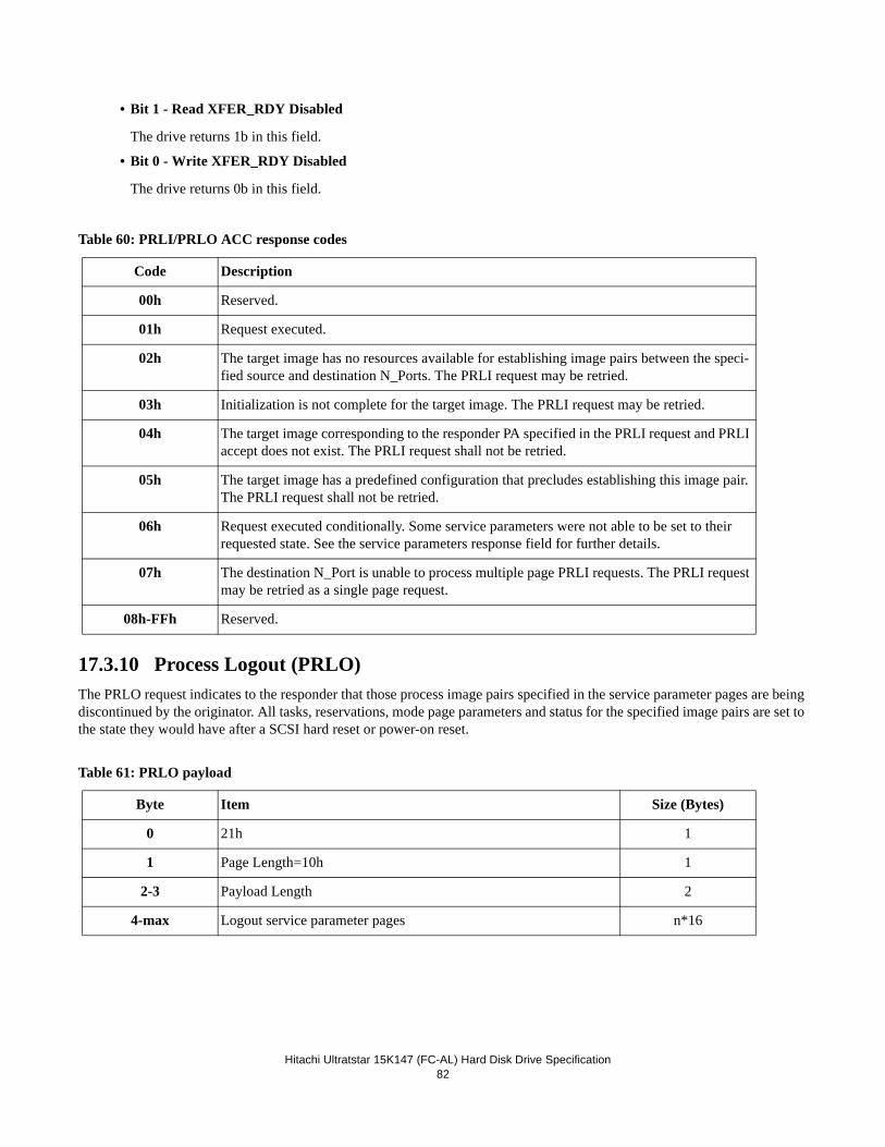
Hitachi Ultratstar 15K147 (FC-AL) Hard Disk Drive Specification82
• Bit 1 - Read XFER_RDY Disabled
The drive returns 1b in this field.
• Bit 0 - Write XFER_RDY Disabled
The drive returns 0b in this field.
Table 60: PRLI/PRLO ACC response codes
17.3.10 Process Logout (PRLO)The PRLO request indicates to the responder that those process image pairs specified in the service parameter pages are being discontinued by the originator. All tasks, reservations, mode page parameters and status for the specified image pairs are set to the state they would have after a SCSI hard reset or power-on reset.
Table 61: PRLO payload
Code Description
00h Reserved.
01h Request executed.
02h The target image has no resources available for establishing image pairs between the speci-fied source and destination N_Ports. The PRLI request may be retried.
03h Initialization is not complete for the target image. The PRLI request may be retried.
04h The target image corresponding to the responder PA specified in the PRLI request and PRLI accept does not exist. The PRLI request shall not be retried.
05h The target image has a predefined configuration that precludes establishing this image pair. The PRLI request shall not be retried.
06h Request executed conditionally. Some service parameters were not able to be set to their requested state. See the service parameters response field for further details.
07h The destination N_Port is unable to process multiple page PRLI requests. The PRLI request may be retried as a single page request.
08h-FFh Reserved.
Byte Item Size (Bytes)
0 21h 1
1 Page Length=10h 1
2-3 Payload Length 2
4-max Logout service parameter pages n*16
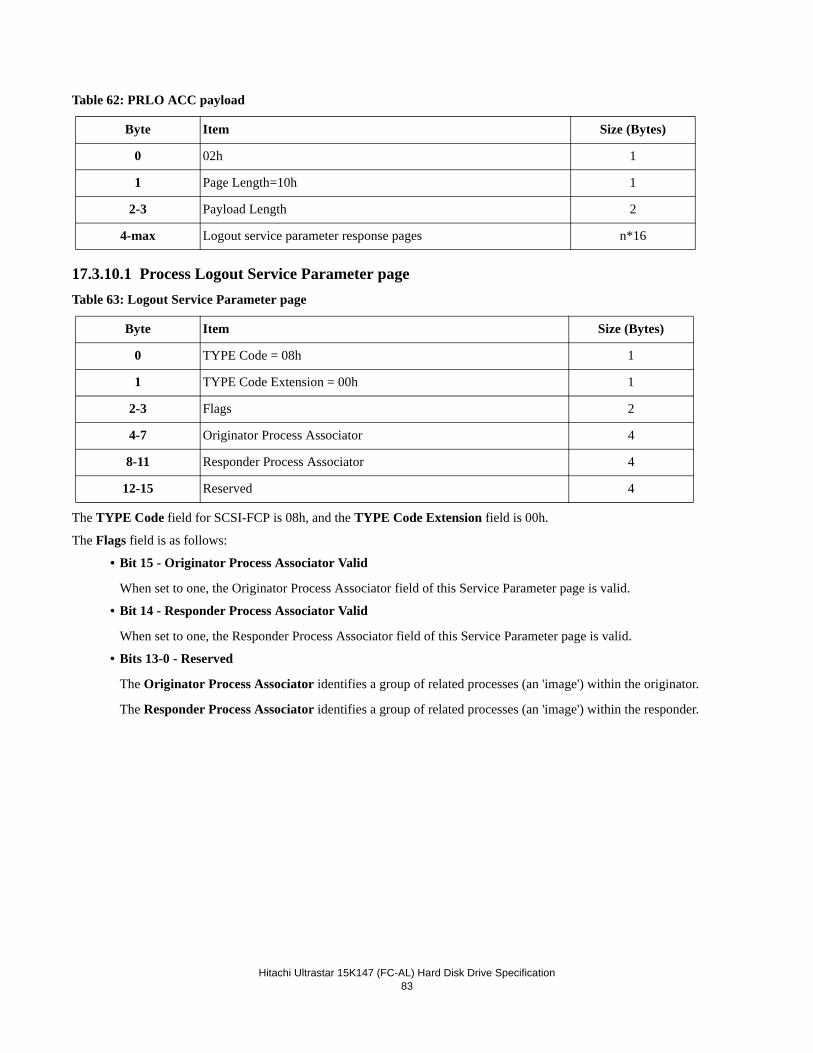
Hitachi Ultrastar 15K147 (FC-AL) Hard Disk Drive Specification83
Table 62: PRLO ACC payload
17.3.10.1 Process Logout Service Parameter pageTable 63: Logout Service Parameter page
The TYPE Code field for SCSI-FCP is 08h, and the TYPE Code Extension field is 00h.
The Flags field is as follows:
• Bit 15 - Originator Process Associator Valid
When set to one, the Originator Process Associator field of this Service Parameter page is valid.
• Bit 14 - Responder Process Associator Valid
When set to one, the Responder Process Associator field of this Service Parameter page is valid.
• Bits 13-0 - Reserved
The Originator Process Associator identifies a group of related processes (an 'image') within the originator.
The Responder Process Associator identifies a group of related processes (an 'image') within the responder.
Byte Item Size (Bytes)
0 02h 1
1 Page Length=10h 1
2-3 Payload Length 2
4-max Logout service parameter response pages n*16
Byte Item Size (Bytes)
0 TYPE Code = 08h 1
1 TYPE Code Extension = 00h 1
2-3 Flags 2
4-7 Originator Process Associator 4
8-11 Responder Process Associator 4
12-15 Reserved 4
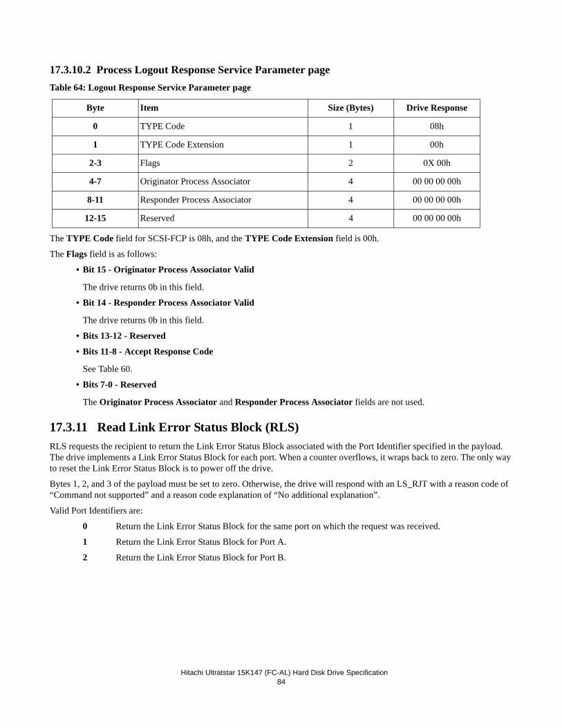
Hitachi Ultratstar 15K147 (FC-AL) Hard Disk Drive Specification84
17.3.10.2 Process Logout Response Service Parameter pageTable 64: Logout Response Service Parameter page
The TYPE Code field for SCSI-FCP is 08h, and the TYPE Code Extension field is 00h.
The Flags field is as follows:
• Bit 15 - Originator Process Associator Valid
The drive returns 0b in this field.
• Bit 14 - Responder Process Associator Valid
The drive returns 0b in this field.
• Bits 13-12 - Reserved
• Bits 11-8 - Accept Response Code
See Table 60.
• Bits 7-0 - Reserved
The Originator Process Associator and Responder Process Associator fields are not used.
17.3.11 Read Link Error Status Block (RLS)RLS requests the recipient to return the Link Error Status Block associated with the Port Identifier specified in the payload. The drive implements a Link Error Status Block for each port. When a counter overflows, it wraps back to zero. The only way to reset the Link Error Status Block is to power off the drive.
Bytes 1, 2, and 3 of the payload must be set to zero. Otherwise, the drive will respond with an LS_RJT with a reason code of “Command not supported” and a reason code explanation of “No additional explanation”.
Valid Port Identifiers are:
0 Return the Link Error Status Block for the same port on which the request was received.
1 Return the Link Error Status Block for Port A.
2 Return the Link Error Status Block for Port B.
Byte Item Size (Bytes) Drive Response
0 TYPE Code 1 08h
1 TYPE Code Extension 1 00h
2-3 Flags 2 0X 00h
4-7 Originator Process Associator 4 00 00 00 00h
8-11 Responder Process Associator 4 00 00 00 00h
12-15 Reserved 4 00 00 00 00h
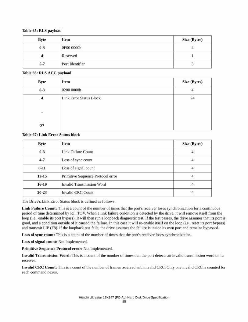
Hitachi Ultrastar 15K147 (FC-AL) Hard Disk Drive Specification85
Table 65: RLS payload
Table 66: RLS ACC payload
Table 67: Link Error Status block
The Drive's Link Error Status block is defined as follows:
Link Failure Count: This is a count of the number of times that the port's receiver loses synchronization for a continuous period of time determined by RT_TOV. When a link failure condition is detected by the drive, it will remove itself from the loop (i.e., enable its port bypass). It will then run a loopback diagnostic test. If the test passes, the drive assumes that its port is good, and a condition outside of it caused the failure. In this case it will re-enable itself on the loop (i.e., reset its port bypass) and transmit LIP (F8). If the loopback test fails, the drive assumes the failure is inside its own port and remains bypassed.
Loss of sync count: This is a count of the number of times that the port's receiver loses synchronization.
Loss of signal count: Not implemented.
Primitive Sequence Protocol error: Not implemented.
Invalid Transmission Word: This is a count of the number of times that the port detects an invalid transmission word on its receiver.
Invalid CRC Count: This is a count of the number of frames received with invalid CRC. Only one invalid CRC is counted for each command nexus.
Byte Item Size (Bytes)
0-3 0F00 0000h 4
4 Reserved 1
5-7 Port Identifier 3
Byte Item Size (Bytes)
0-3 0200 0000h 4
4
-
27
Link Error Status Block 24
Byte Item Size (Bytes)
0-3 Link Failure Count 4
4-7 Loss of sync count 4
8-11 Loss of signal count 4
12-15 Primitive Sequence Protocol error 4
16-19 Invalid Transmission Word 4
20-23 Invalid CRC Count 4
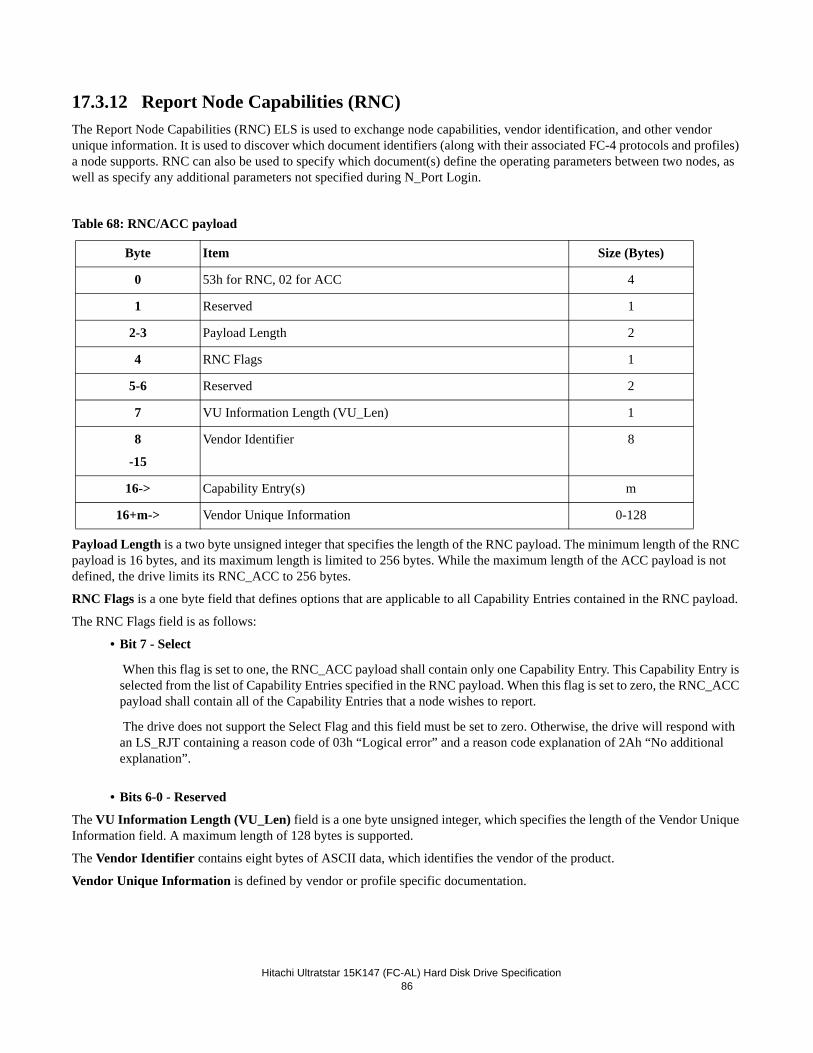
Hitachi Ultratstar 15K147 (FC-AL) Hard Disk Drive Specification86
17.3.12 Report Node Capabilities (RNC)The Report Node Capabilities (RNC) ELS is used to exchange node capabilities, vendor identification, and other vendor unique information. It is used to discover which document identifiers (along with their associated FC-4 protocols and profiles) a node supports. RNC can also be used to specify which document(s) define the operating parameters between two nodes, as well as specify any additional parameters not specified during N_Port Login.
Table 68: RNC/ACC payload
Payload Length is a two byte unsigned integer that specifies the length of the RNC payload. The minimum length of the RNC payload is 16 bytes, and its maximum length is limited to 256 bytes. While the maximum length of the ACC payload is not defined, the drive limits its RNC_ACC to 256 bytes.
RNC Flags is a one byte field that defines options that are applicable to all Capability Entries contained in the RNC payload.
The RNC Flags field is as follows:
• Bit 7 - Select
When this flag is set to one, the RNC_ACC payload shall contain only one Capability Entry. This Capability Entry is selected from the list of Capability Entries specified in the RNC payload. When this flag is set to zero, the RNC_ACC payload shall contain all of the Capability Entries that a node wishes to report.
The drive does not support the Select Flag and this field must be set to zero. Otherwise, the drive will respond with an LS_RJT containing a reason code of 03h “Logical error” and a reason code explanation of 2Ah “No additional explanation”.
• Bits 6-0 - Reserved
The VU Information Length (VU_Len) field is a one byte unsigned integer, which specifies the length of the Vendor Unique Information field. A maximum length of 128 bytes is supported.
The Vendor Identifier contains eight bytes of ASCII data, which identifies the vendor of the product.
Vendor Unique Information is defined by vendor or profile specific documentation.
Byte Item Size (Bytes)
0 53h for RNC, 02 for ACC 4
1 Reserved 1
2-3 Payload Length 2
4 RNC Flags 1
5-6 Reserved 2
7 VU Information Length (VU_Len) 1
8
-15
Vendor Identifier 8
16-> Capability Entry(s) m
16+m-> Vendor Unique Information 0-128
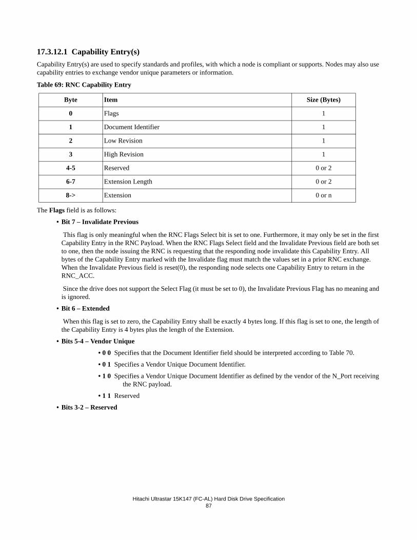
Hitachi Ultrastar 15K147 (FC-AL) Hard Disk Drive Specification87
17.3.12.1 Capability Entry(s) Capability Entry(s) are used to specify standards and profiles, with which a node is compliant or supports. Nodes may also use capability entries to exchange vendor unique parameters or information.
Table 69: RNC Capability Entry
The Flags field is as follows:
• Bit 7 – Invalidate Previous
This flag is only meaningful when the RNC Flags Select bit is set to one. Furthermore, it may only be set in the first Capability Entry in the RNC Payload. When the RNC Flags Select field and the Invalidate Previous field are both set to one, then the node issuing the RNC is requesting that the responding node invalidate this Capability Entry. All bytes of the Capability Entry marked with the Invalidate flag must match the values set in a prior RNC exchange. When the Invalidate Previous field is reset(0), the responding node selects one Capability Entry to return in the RNC_ACC.
Since the drive does not support the Select Flag (it must be set to 0), the Invalidate Previous Flag has no meaning and is ignored.
• Bit 6 – Extended
When this flag is set to zero, the Capability Entry shall be exactly 4 bytes long. If this flag is set to one, the length of the Capability Entry is 4 bytes plus the length of the Extension.
• Bits 5-4 – Vendor Unique
• 0 0 Specifies that the Document Identifier field should be interpreted according to Table 70.
• 0 1 Specifies a Vendor Unique Document Identifier.
• 1 0 Specifies a Vendor Unique Document Identifier as defined by the vendor of the N_Port receiving the RNC payload.
• 1 1 Reserved
• Bits 3-2 – Reserved
Byte Item Size (Bytes)
0 Flags 1
1 Document Identifier 1
2 Low Revision 1
3 High Revision 1
4-5 Reserved 0 or 2
6-7 Extension Length 0 or 2
8-> Extension 0 or n
Hitachi Ultratstar 15K147 (FC-AL) Hard Disk Drive Specification88
• Bits 1-0 - Preference
Preference is a two bit value that indicates the level of support or performance relative to the other capabilities sup-ported by the node. It is used to aid a node in selecting a specific capability when multiple capabilities are supported. The Preference field has a range from 0 to 3.
• 0 0 Best
• 0 1
• 1 0
• 1 1 Worst
The drive does not support the Preference field ignores it.
The Document Identifier field specifies which Profile or Standard is associated with each Capability Entry. Valid Document Identifiers are listed in Table 70. If the Vendor Unique Flag is set to a value other than 00h, then the Document Identifier spec-ifies a vendor unique capability.
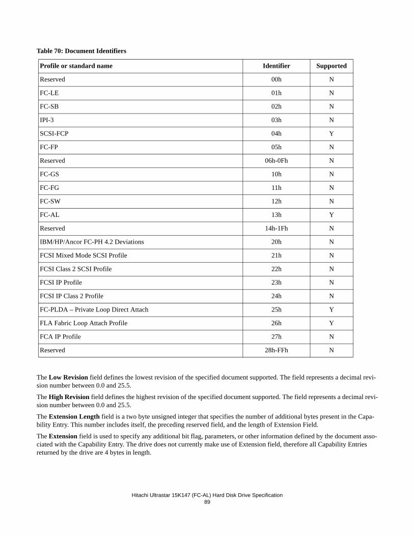
Hitachi Ultrastar 15K147 (FC-AL) Hard Disk Drive Specification89
Table 70: Document Identifiers
The Low Revision field defines the lowest revision of the specified document supported. The field represents a decimal revi-sion number between 0.0 and 25.5.
The High Revision field defines the highest revision of the specified document supported. The field represents a decimal revi-sion number between 0.0 and 25.5.
The Extension Length field is a two byte unsigned integer that specifies the number of additional bytes present in the Capa-bility Entry. This number includes itself, the preceding reserved field, and the length of Extension Field.
The Extension field is used to specify any additional bit flag, parameters, or other information defined by the document asso-ciated with the Capability Entry. The drive does not currently make use of Extension field, therefore all Capability Entries returned by the drive are 4 bytes in length.
Profile or standard name Identifier Supported
Reserved 00h N
FC-LE 01h N
FC-SB 02h N
IPI-3 03h N
SCSI-FCP 04h Y
FC-FP 05h N
Reserved 06h-0Fh N
FC-GS 10h N
FC-FG 11h N
FC-SW 12h N
FC-AL 13h Y
Reserved 14h-1Fh N
IBM/HP/Ancor FC-PH 4.2 Deviations 20h N
FCSI Mixed Mode SCSI Profile 21h N
FCSI Class 2 SCSI Profile 22h N
FCSI IP Profile 23h N
FCSI IP Class 2 Profile 24h N
FC-PLDA – Private Loop Direct Attach 25h Y
FLA Fabric Loop Attach Profile 26h Y
FCA IP Profile 27h N
Reserved 28h-FFh N
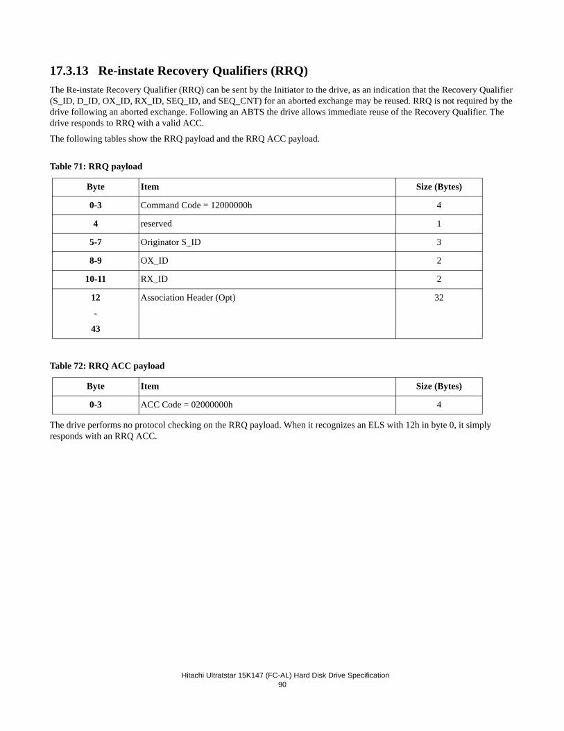
Hitachi Ultratstar 15K147 (FC-AL) Hard Disk Drive Specification90
17.3.13 Re-instate Recovery Qualifiers (RRQ)The Re-instate Recovery Qualifier (RRQ) can be sent by the Initiator to the drive, as an indication that the Recovery Qualifier (S_ID, D_ID, OX_ID, RX_ID, SEQ_ID, and SEQ_CNT) for an aborted exchange may be reused. RRQ is not required by the drive following an aborted exchange. Following an ABTS the drive allows immediate reuse of the Recovery Qualifier. The drive responds to RRQ with a valid ACC.
The following tables show the RRQ payload and the RRQ ACC payload.
Table 71: RRQ payload
Table 72: RRQ ACC payload
The drive performs no protocol checking on the RRQ payload. When it recognizes an ELS with 12h in byte 0, it simply responds with an RRQ ACC.
Byte Item Size (Bytes)
0-3 Command Code = 12000000h 4
4 reserved 1
5-7 Originator S_ID 3
8-9 OX_ID 2
10-11 RX_ID 2
12
-
43
Association Header (Opt) 32
Byte Item Size (Bytes)
0-3 ACC Code = 02000000h 4
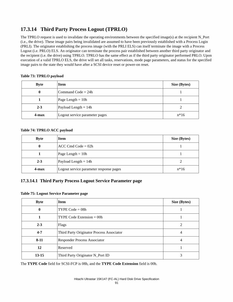
Hitachi Ultrastar 15K147 (FC-AL) Hard Disk Drive Specification91
17.3.14 Third Party Process Logout (TPRLO)The TPRLO request is used to invalidate the operating environments between the specified image(s) at the recipient N_Port (i.e., the drive). These image pairs being invalidated are assumed to have been previously established with a Process Login (PRLI). The originator establishing the process image (with the PRLI ELS) can itself terminate the image with a Process Logout (i.e. PRLO) ELS. An originator can terminate the process pair established between another third party originator and the recipient (i.e. the drive) using TPRLO. TPRLO has the same effect as if the third party originator performed PRLO. Upon execution of a valid TPRLO ELS, the drive will set all tasks, reservations, mode page parameters, and status for the specified image pairs to the state they would have after a SCSI device reset or power-on reset.
Table 73: TPRLO payload
Table 74: TPRLO ACC payload
17.3.14.1 Third Party Process Logout Service Parameter page
Table 75: Logout Service Parameter page
The TYPE Code field for SCSI-FCP is 08h, and the TYPE Code Extension field is 00h.
Byte Item Size (Bytes)
0 Command Code = 24h 1
1 Page Length = 10h 1
2-3 Payload Length = 14h 2
4-max Logout service parameter pages n*16
Byte Item Size (Bytes)
0 ACC Cmd Code = 02h 1
1 Page Length = 10h 1
2-3 Payload Length = 14h 2
4-max Logout service parameter response pages n*16
Byte Item Size (Bytes)
0 TYPE Code = 08h 1
1 TYPE Code Extension = 00h 1
2-3 Flags 2
4-7 Third Party Originator Process Associator 4
8-11 Responder Process Associator 4
12 Reserved 1
13-15 Third Party Originator N_Port ID 3
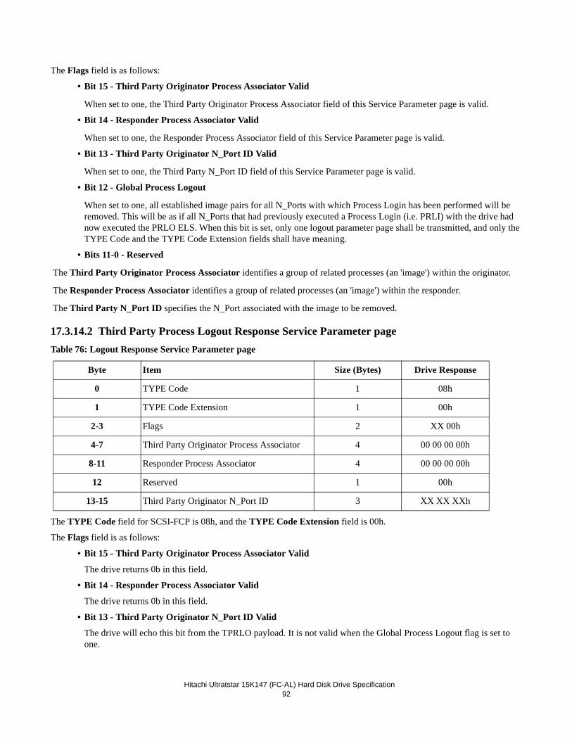
Hitachi Ultratstar 15K147 (FC-AL) Hard Disk Drive Specification92
The Flags field is as follows:
• Bit 15 - Third Party Originator Process Associator Valid
When set to one, the Third Party Originator Process Associator field of this Service Parameter page is valid.
• Bit 14 - Responder Process Associator Valid
When set to one, the Responder Process Associator field of this Service Parameter page is valid.
• Bit 13 - Third Party Originator N_Port ID Valid
When set to one, the Third Party N_Port ID field of this Service Parameter page is valid.
• Bit 12 - Global Process Logout
When set to one, all established image pairs for all N_Ports with which Process Login has been performed will be removed. This will be as if all N_Ports that had previously executed a Process Login (i.e. PRLI) with the drive had now executed the PRLO ELS. When this bit is set, only one logout parameter page shall be transmitted, and only the TYPE Code and the TYPE Code Extension fields shall have meaning.
• Bits 11-0 - Reserved
The Third Party Originator Process Associator identifies a group of related processes (an 'image') within the originator.
The Responder Process Associator identifies a group of related processes (an 'image') within the responder.
The Third Party N_Port ID specifies the N_Port associated with the image to be removed.
17.3.14.2 Third Party Process Logout Response Service Parameter pageTable 76: Logout Response Service Parameter page
The TYPE Code field for SCSI-FCP is 08h, and the TYPE Code Extension field is 00h.
The Flags field is as follows:
• Bit 15 - Third Party Originator Process Associator Valid
The drive returns 0b in this field.
• Bit 14 - Responder Process Associator Valid
The drive returns 0b in this field.
• Bit 13 - Third Party Originator N_Port ID Valid
The drive will echo this bit from the TPRLO payload. It is not valid when the Global Process Logout flag is set to one.
Byte Item Size (Bytes) Drive Response
0 TYPE Code 1 08h
1 TYPE Code Extension 1 00h
2-3 Flags 2 XX 00h
4-7 Third Party Originator Process Associator 4 00 00 00 00h
8-11 Responder Process Associator 4 00 00 00 00h
12 Reserved 1 00h
13-15 Third Party Originator N_Port ID 3 XX XX XXh
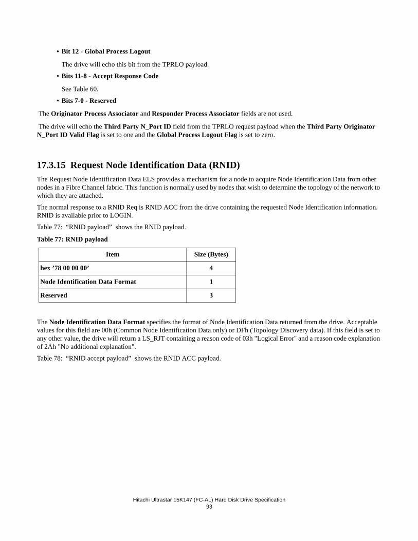
Hitachi Ultrastar 15K147 (FC-AL) Hard Disk Drive Specification93
• Bit 12 - Global Process Logout
The drive will echo this bit from the TPRLO payload.
• Bits 11-8 - Accept Response Code
See Table 60.
• Bits 7-0 - Reserved
The Originator Process Associator and Responder Process Associator fields are not used.
The drive will echo the Third Party N_Port ID field from the TPRLO request payload when the Third Party Originator N_Port ID Valid Flag is set to one and the Global Process Logout Flag is set to zero.
17.3.15 Request Node Identification Data (RNID)The Request Node Identification Data ELS provides a mechanism for a node to acquire Node Identification Data from other nodes in a Fibre Channel fabric. This function is normally used by nodes that wish to determine the topology of the network to which they are attached.
The normal response to a RNID Req is RNID ACC from the drive containing the requested Node Identification information. RNID is available prior to LOGIN.
Table 77: “RNID payload” shows the RNID payload.
Table 77: RNID payload
The Node Identification Data Format specifies the format of Node Identification Data returned from the drive. Acceptable values for this field are 00h (Common Node Identification Data only) or DFh (Topology Discovery data). If this field is set to any other value, the drive will return a LS_RJT containing a reason code of 03h "Logical Error" and a reason code explanation of 2Ah "No additional explanation".
Table 78: “RNID accept payload” shows the RNID ACC payload.
Item Size (Bytes)
hex ’78 00 00 00’ 4
Node Identification Data Format 1
Reserved 3
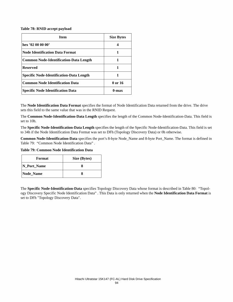
Hitachi Ultratstar 15K147 (FC-AL) Hard Disk Drive Specification94
Table 78: RNID accept payload
The Node Identification Data Format specifies the format of Node Identification Data returned from the drive. The drive sets this field to the same value that was in the RNID Request.
The Common Node-Identification-Data Length specifies the length of the Common Node-Identification-Data. This field is set to 10h.
The Specific Node-Identification-Data Length specifies the length of the Specific Node-Identification-Data. This field is set to 34h if the Node Identification Data Format was set to DFh (Topology Discovery Data) or 0h otherwise.
Common Node-Identification-Data specifies the port’s 8-byte Node_Name and 8-byte Port_Name. The format is defined in Table 79: “Common Node Identification Data” .
Table 79: Common Node Identification Data
The Specific Node-Identification-Data specifies Topology Discovery Data whose format is described in Table 80: “Topol-ogy Discovery Specific Node Identification Data” . This Data is only returned when the Node Identification Data Format is set to DFh "Topology Discovery Data".
Item Size Bytes
hex ’02 00 00 00’ 4
Node Identification Data Format 1
Common Node-Identification-Data Length 1
Reserved 1
Specific Node-Identification-Data Length 1
Common Node Identification Data 0 or 16
Specific Node Identification Data 0-max
Format Size (Bytes)
N_Port_Name 8
Node_Name 8
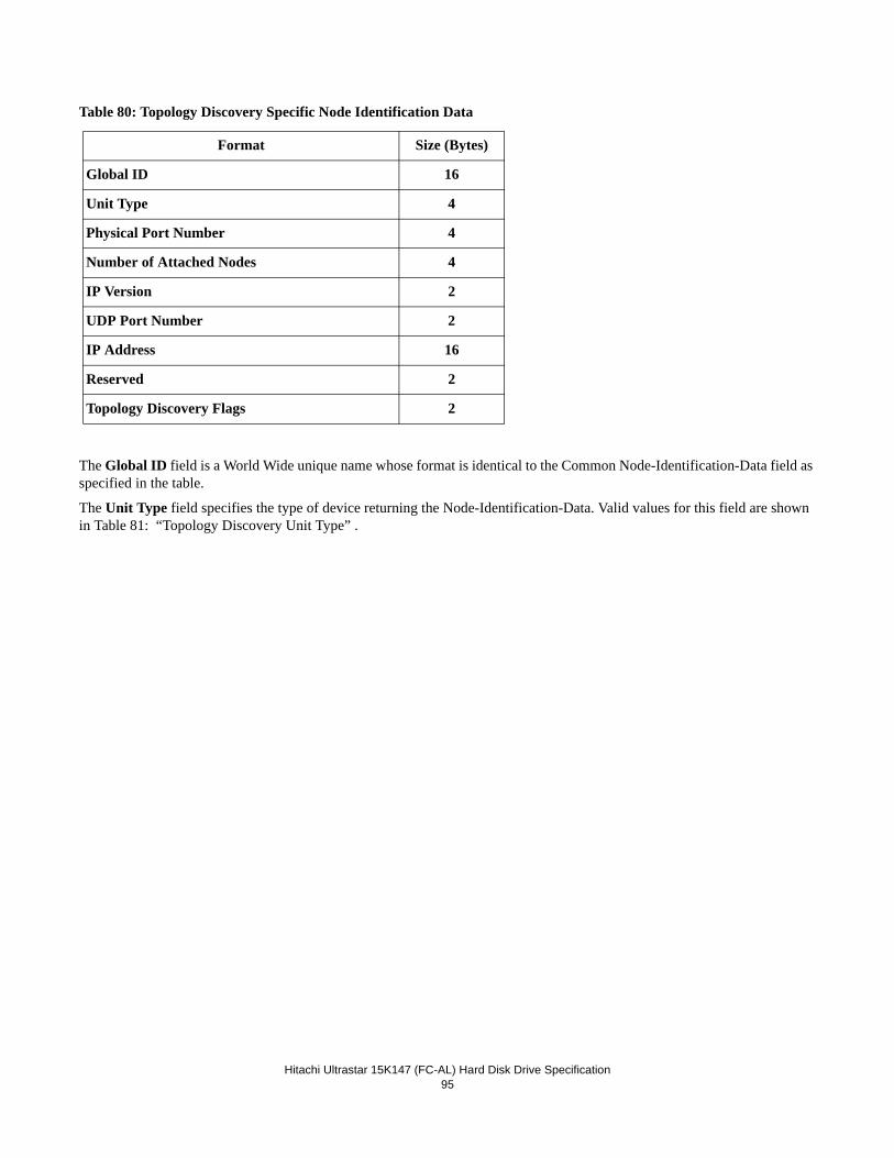
Hitachi Ultrastar 15K147 (FC-AL) Hard Disk Drive Specification95
Table 80: Topology Discovery Specific Node Identification Data
The Global ID field is a World Wide unique name whose format is identical to the Common Node-Identification-Data field as specified in the table.
The Unit Type field specifies the type of device returning the Node-Identification-Data. Valid values for this field are shown in Table 81: “Topology Discovery Unit Type” .
Format Size (Bytes)
Global ID 16
Unit Type 4
Physical Port Number 4
Number of Attached Nodes 4
IP Version 2
UDP Port Number 2
IP Address 16
Reserved 2
Topology Discovery Flags 2
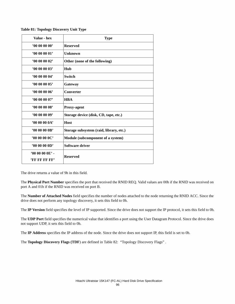
Hitachi Ultratstar 15K147 (FC-AL) Hard Disk Drive Specification96
Table 81: Topology Discovery Unit Type
The drive returns a value of 9h in this field.
The Physical Port Number specifies the port that received the RNID REQ. Valid values are 00h if the RNID was received on port A and 01h if the RNID was received on port B.
The Number of Attached Nodes field specifies the number of nodes attached to the node returning the RNID ACC. Since the drive does not perform any topology discovery, it sets this field to 0h.
The IP Version field specifies the level of IP supported. Since the drive does not support the IP protocol, it sets this field to 0h.
The UDP Port field specifies the numerical value that identifies a port using the User Datagram Protocol. Since the drive does not support UDP, it sets this field to 0h.
The IP Address specifies the IP address of the node. Since the drive does not support IP, this field is set to 0h.
The Topology Discovery Flags (TDF) are defined in Table 82: “Topology Discovery Flags” .
Value - hex Type
’00 00 00 00’ Reserved
’00 00 00 01’ Unknown
’00 00 00 02’ Other (none of the following)
’00 00 00 03’ Hub
’00 00 00 04’ Switch
’00 00 00 05’ Gateway
’00 00 00 06’ Converter
’00 00 00 07’ HBA
’00 00 00 08’ Proxy-agent
’00 00 00 09’ Storage device (disk, CD, tape, etc.)
’00 00 00 0A’ Host
’00 00 00 0B’ Storage subsystem (raid, library, etc.)
’00 00 00 0C’ Module (subcomponent of a system)
’00 00 00 0D’ Software driver
’00 00 00 0E’ -
’FF FF FF FF’Reserved
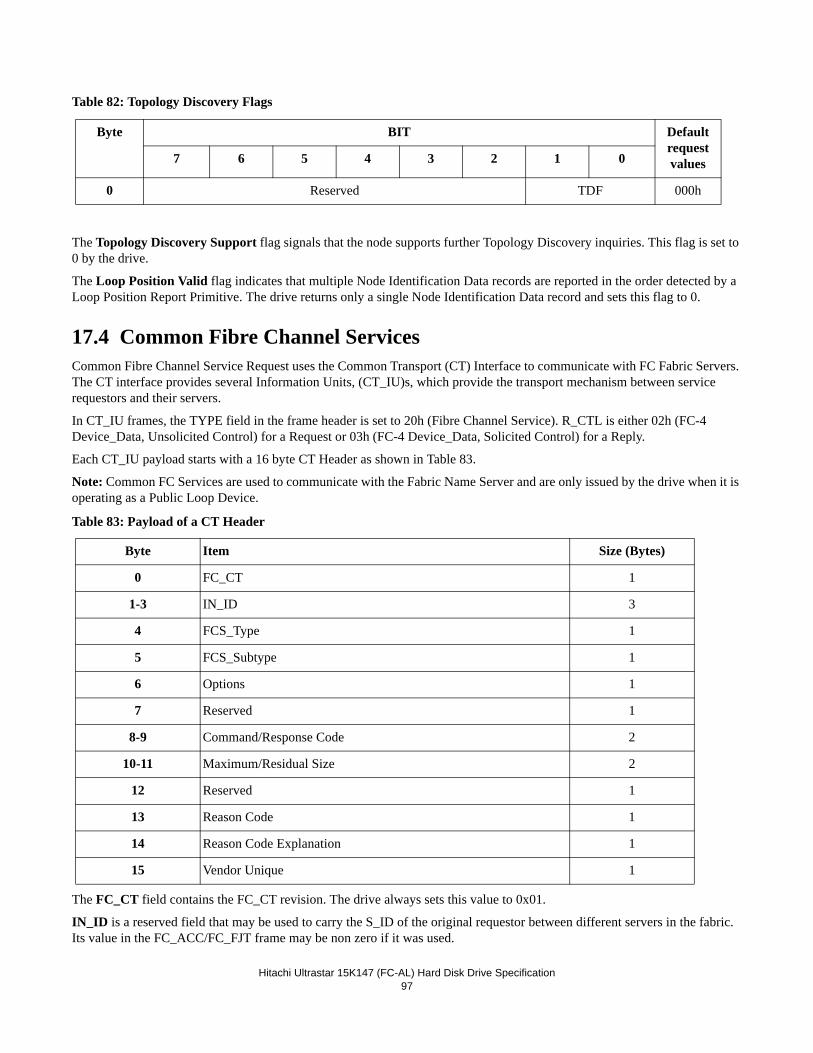
Hitachi Ultrastar 15K147 (FC-AL) Hard Disk Drive Specification97
Table 82: Topology Discovery Flags
The Topology Discovery Support flag signals that the node supports further Topology Discovery inquiries. This flag is set to 0 by the drive.
The Loop Position Valid flag indicates that multiple Node Identification Data records are reported in the order detected by a Loop Position Report Primitive. The drive returns only a single Node Identification Data record and sets this flag to 0.
17.4 Common Fibre Channel ServicesCommon Fibre Channel Service Request uses the Common Transport (CT) Interface to communicate with FC Fabric Servers. The CT interface provides several Information Units, (CT_IU)s, which provide the transport mechanism between service requestors and their servers.
In CT_IU frames, the TYPE field in the frame header is set to 20h (Fibre Channel Service). R_CTL is either 02h (FC-4 Device_Data, Unsolicited Control) for a Request or 03h (FC-4 Device_Data, Solicited Control) for a Reply.
Each CT_IU payload starts with a 16 byte CT Header as shown in Table 83.
Note: Common FC Services are used to communicate with the Fabric Name Server and are only issued by the drive when it is operating as a Public Loop Device.
Table 83: Payload of a CT Header
The FC_CT field contains the FC_CT revision. The drive always sets this value to 0x01.
IN_ID is a reserved field that may be used to carry the S_ID of the original requestor between different servers in the fabric. Its value in the FC_ACC/FC_FJT frame may be non zero if it was used.
Byte BIT Defaultrequest values7 6 5 4 3 2 1 0
0 Reserved TDF 000h
Byte Item Size (Bytes)
0 FC_CT 1
1-3 IN_ID 3
4 FCS_Type 1
5 FCS_Subtype 1
6 Options 1
7 Reserved 1
8-9 Command/Response Code 2
10-11 Maximum/Residual Size 2
12 Reserved 1
13 Reason Code 1
14 Reason Code Explanation 1
15 Vendor Unique 1
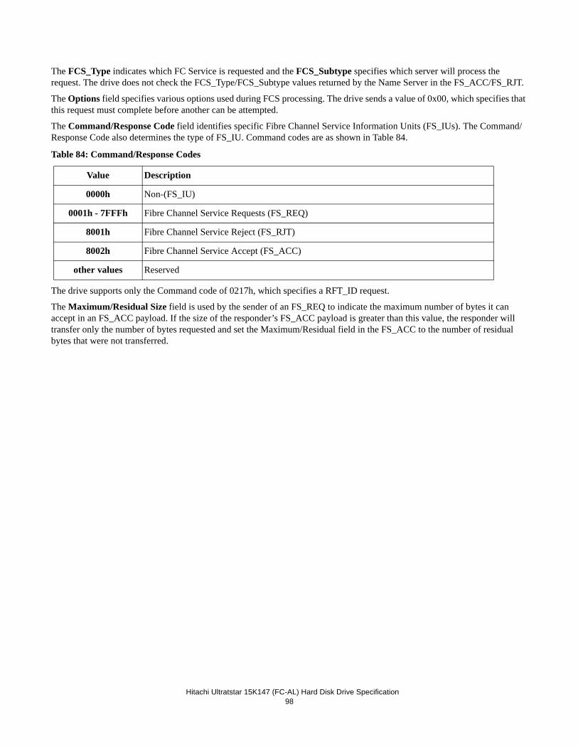
Hitachi Ultratstar 15K147 (FC-AL) Hard Disk Drive Specification98
The FCS_Type indicates which FC Service is requested and the FCS_Subtype specifies which server will process the request. The drive does not check the FCS_Type/FCS_Subtype values returned by the Name Server in the FS_ACC/FS_RJT.
The Options field specifies various options used during FCS processing. The drive sends a value of 0x00, which specifies that this request must complete before another can be attempted.
The Command/Response Code field identifies specific Fibre Channel Service Information Units (FS_IUs). The Command/Response Code also determines the type of FS_IU. Command codes are as shown in Table 84.
Table 84: Command/Response Codes
The drive supports only the Command code of 0217h, which specifies a RFT_ID request.
The Maximum/Residual Size field is used by the sender of an FS_REQ to indicate the maximum number of bytes it can accept in an FS_ACC payload. If the size of the responder’s FS_ACC payload is greater than this value, the responder will transfer only the number of bytes requested and set the Maximum/Residual field in the FS_ACC to the number of residual bytes that were not transferred.
Value Description
0000h Non-(FS_IU)
0001h - 7FFFh Fibre Channel Service Requests (FS_REQ)
8001h Fibre Channel Service Reject (FS_RJT)
8002h Fibre Channel Service Accept (FS_ACC)
other values Reserved
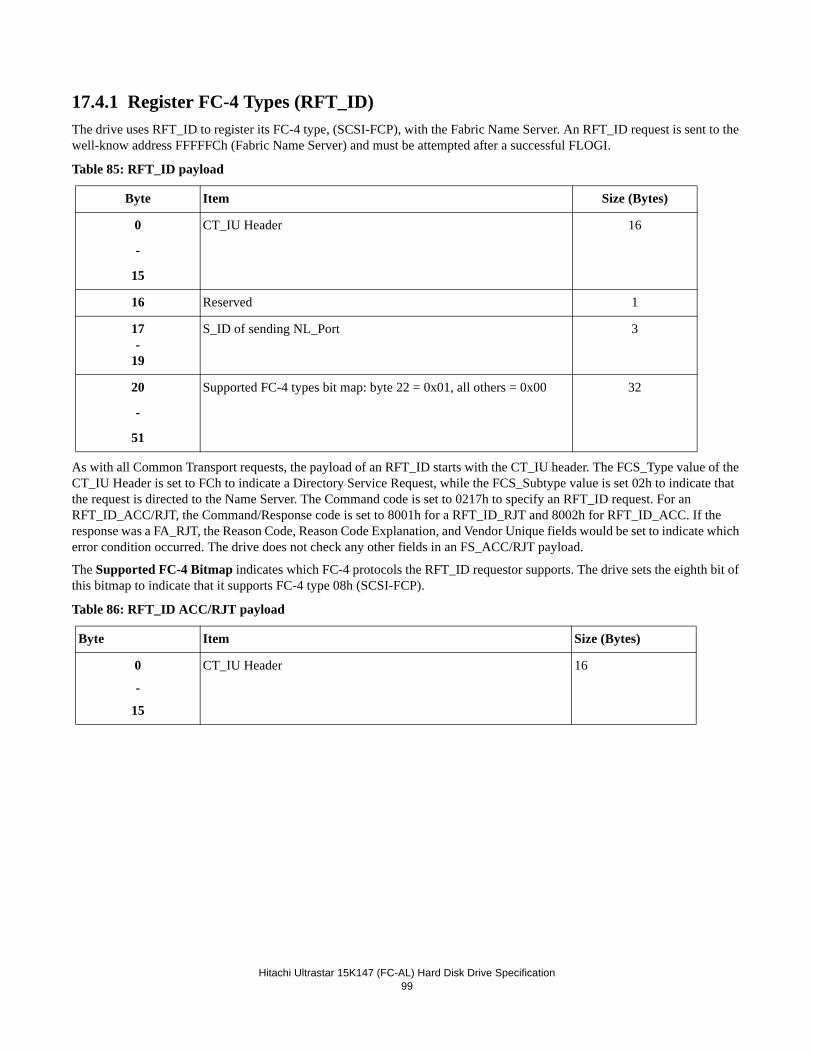
Hitachi Ultrastar 15K147 (FC-AL) Hard Disk Drive Specification99
17.4.1 Register FC-4 Types (RFT_ID)The drive uses RFT_ID to register its FC-4 type, (SCSI-FCP), with the Fabric Name Server. An RFT_ID request is sent to the well-know address FFFFFCh (Fabric Name Server) and must be attempted after a successful FLOGI.
Table 85: RFT_ID payload
As with all Common Transport requests, the payload of an RFT_ID starts with the CT_IU header. The FCS_Type value of the CT_IU Header is set to FCh to indicate a Directory Service Request, while the FCS_Subtype value is set 02h to indicate that the request is directed to the Name Server. The Command code is set to 0217h to specify an RFT_ID request. For an RFT_ID_ACC/RJT, the Command/Response code is set to 8001h for a RFT_ID_RJT and 8002h for RFT_ID_ACC. If the response was a FA_RJT, the Reason Code, Reason Code Explanation, and Vendor Unique fields would be set to indicate which error condition occurred. The drive does not check any other fields in an FS_ACC/RJT payload.
The Supported FC-4 Bitmap indicates which FC-4 protocols the RFT_ID requestor supports. The drive sets the eighth bit of this bitmap to indicate that it supports FC-4 type 08h (SCSI-FCP).
Table 86: RFT_ID ACC/RJT payload
Byte Item Size (Bytes)
0
-
15
CT_IU Header 16
16 Reserved 1
17-
19
S_ID of sending NL_Port 3
20
-
51
Supported FC-4 types bit map: byte 22 = 0x01, all others = 0x00 32
Byte Item Size (Bytes)
0
-
15
CT_IU Header 16
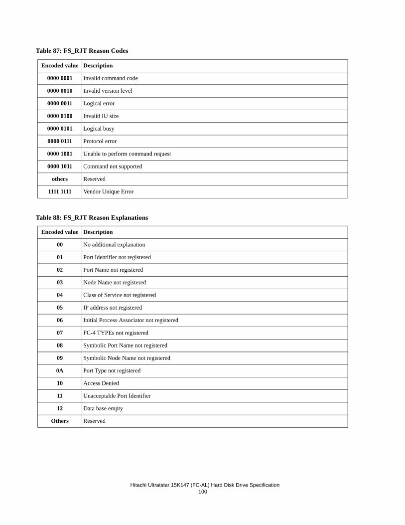
Hitachi Ultratstar 15K147 (FC-AL) Hard Disk Drive Specification100
Table 87: FS_RJT Reason Codes
Table 88: FS_RJT Reason Explanations
Encoded value Description
0000 0001 Invalid command code
0000 0010 Invalid version level
0000 0011 Logical error
0000 0100 Invalid IU size
0000 0101 Logical busy
0000 0111 Protocol error
0000 1001 Unable to perform command request
0000 1011 Command not supported
others Reserved
1111 1111 Vendor Unique Error
Encoded value Description
00 No additional explanation
01 Port Identifier not registered
02 Port Name not registered
03 Node Name not registered
04 Class of Service not registered
05 IP address not registered
06 Initial Process Associator not registered
07 FC-4 TYPEs not registered
08 Symbolic Port Name not registered
09 Symbolic Node Name not registered
0A Port Type not registered
10 Access Denied
11 Unacceptable Port Identifier
12 Data base empty
Others Reserved
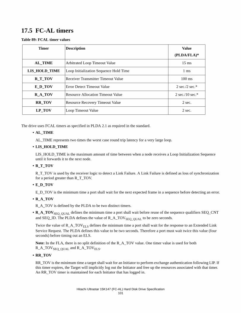
Hitachi Ultrastar 15K147 (FC-AL) Hard Disk Drive Specification101
17.5 FC-AL timersTable 89: FCAL timer values
The drive uses FCAL timers as specified in PLDA 2.1 as required in the standard.
• AL_TIME
AL_TIME represents two times the worst case round trip latency for a very large loop.
• LIS_HOLD_TIME
LIS_HOLD_TIME is the maximum amount of time between when a node receives a Loop Initialization Sequence until it forwards it to the next node.
• R_T_TOV
R_T_TOV is used by the receiver logic to detect a Link Failure. A Link Failure is defined as loss of synchronization for a period greater than R_T_TOV.
• E_D_TOV
E_D_TOV is the minimum time a port shall wait for the next expected frame in a sequence before detecting an error.
• R_A_TOV
R_A_TOV is defined by the PLDA to be two distinct timers.
• R_A_TOVSEQ_QUAL defines the minimum time a port shall wait before reuse of the sequence qualifiers SEQ_CNT and SEQ_ID. The PLDA defines the value of R_A_TOVSEQ_QUAL to be zero seconds.
Twice the value of R_A_TOVELS defines the minimum time a port shall wait for the response to an Extended Link Service Request. The PLDA defines this value to be two seconds. Therefore a port must wait twice this value (four seconds) before timing out an ELS.
Note: In the FLA, there is no split definition of the R_A_TOV value. One timer value is used for both R_A_TOVSEQ_QUAL and R_A_TOVELS.
• RR_TOV
RR_TOV is the minimum time a target shall wait for an Initiator to perform exchange authentication following LIP. If this timer expires, the Target will implicitly log out the Initiator and free up the resources associated with that timer. An RR_TOV timer is maintained for each Initiator that has logged in.
Timer Description Value
(PLDA/FLA)*
AL_TIME Arbitrated Loop Timeout Value 15 ms
LIS_HOLD_TIME Loop Initialization Sequence Hold Time 1 ms
R_T_TOV Receiver Transmitter Timeout Value 100 ms
E_D_TOV Error Detect Timeout Value 2 sec./2 sec.*
R_A_TOV Resource Allocation Timeout Value 2 sec./10 sec.*
RR_TOV Resource Recovery Timeout Value 2 sec.
LP_TOV Loop Timeout Value 2 sec.
Hitachi Ultratstar 15K147 (FC-AL) Hard Disk Drive Specification102
• LP_TOV
LP_TOV is used to keep a Loop from deteriorating due to protocol errors or lost Ordered Sets.
LP_TOV is also used during initialization and to reset the fairness window.
17.5.1 Link Failure Link Failure is defined when a receiver has continuously detected loss of synchronization for a period of R_T_TOV. When this occurs, the port will bypass itself and run a loopback test. If the loopback test passes, the port assumes that it is not the cause of the loop failure, and it resets its bypass circuit and transmits a LIP(F8). When it receives its own LIP(F8), the drives assumes the loop is now intact and issues a LIP(F7). If the port’s loopback test fails, it assumes that it was the cause of the loop failure, and it remains in the bypassed state.
17.6 Invalid frame delimiterIf an invalid frame delimiter is received for a:
•- FCP_DATA frame, the exchange shall terminate with a CHECK CONDITION status. The resulting Sense data will have the Sense Key set to Aborted command and the Additional Sense Code set to Data Phase Error.
•- non-FCP_DATA frame, the frame shall be discarded and ignored.
Hitachi Ultrastar 15K147 (FC-AL) Hard Disk Drive Specification103
18.0 SCSI-FCPThis section describes the drive’s implementation of SCSI-FCP. SCSI-FCP is the FC-4 mapping recommended by the Disk Profile. It maps the ANSI SCSI protocol onto the FC-PH functions.
Note: PLDA 2.1 specifies: “Reserved FC-PH fields are not required to be checked for zeroes. Validity bits set to 0 remove any requirement to check the corresponding field for zeroes (e.g., if F_CTL bit 3=0, receiving N_Ports are not required to verify that the parameter field in word 5 of the frame header contains zeroes).” As such, the drive does not validate 1) reserved FC fields or 2) fields that are not reserved but are not valid for the current frame (as the example above with F_CTL bit 3). This does not apply to any reserved field checking and testing within the FCP_CDB. These fields are checked as per ANSI SCSI requirements.
18.1 TerminologyThe SCSI Architecture Model (SAM) defines a new SCSI vocabulary in order to remain independent from physical protocol and interconnect. Common SCSI-2 terms have been replaced and new ones introduced.
As might be expected, the terminology used to describe SCSI-FCP is a problem. It needs elements of SAM and Fibre Channel. Most of the Fibre Channel terms have been introduced in 1.0, “FC-AL Attachment”, and some essential SAM terms are cov-ered here. However, SAM is still recommended reading!
SCSI-FCP describes all communication in terms of Fibre Channel Information Units (IUs). FC-PH defines these simply as "sequences that have special meaning to the FC-4" (i.e. SCSI-FCP).
IUs are used to send commands, data, and status; bus phases are part of parallel SCSI and no longer exist. Execution of a com-mand requires several IUs to pass between theTarget and Initiator so an I/O Process (IOP) equates to a Fibre Channel exchange. In fact, the exchange ID is used as the command tag.
An IOP is represented in the Target by a Task. The Initiator uses Task Management functions to control execution of the task in the Target. IUs are used to transfer Task Management functions.
SAM defines a Target as consisting of a Task Manager and one or more Logical Units. The Task Manager handles all the Task Management functions and the logical unit handles commands.
The logical unit consists of a Target and a Task Set. The Target actually executes the commands and the task set is simply what used to be known as the Command Queue.
SCSI-FCP recognizes that Targets and Initiators may simply be software procedures and therefore calls them Processes.
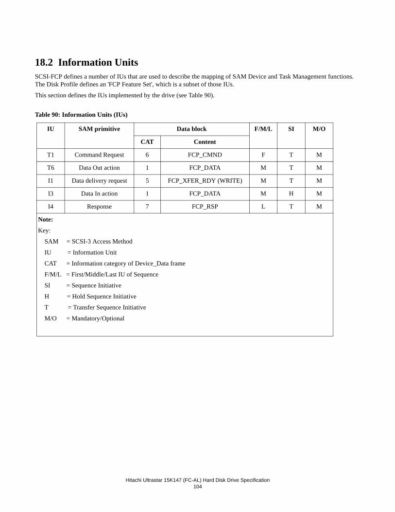
Hitachi Ultrastar 15K147 (FC-AL) Hard Disk Drive Specification104
18.2 Information UnitsSCSI-FCP defines a number of IUs that are used to describe the mapping of SAM Device and Task Management functions. The Disk Profile defines an 'FCP Feature Set', which is a subset of those IUs.
This section defines the IUs implemented by the drive (see Table 90).
Table 90: Information Units (IUs)
IU SAM primitive Data block F/M/L SI M/O
CAT Content
T1 Command Request 6 FCP_CMND F T M
T6 Data Out action 1 FCP_DATA M T M
I1 Data delivery request 5 FCP_XFER_RDY (WRITE) M T M
I3 Data In action 1 FCP_DATA M H M
I4 Response 7 FCP_RSP L T M
Note:
Key:
SAM = SCSI-3 Access Method
IU = Information Unit
CAT = Information category of Device_Data frame
F/M/L = First/Middle/Last IU of Sequence
SI = Sequence Initiative
H = Hold Sequence Initiative
T = Transfer Sequence Initiative
M/O = Mandatory/Optional
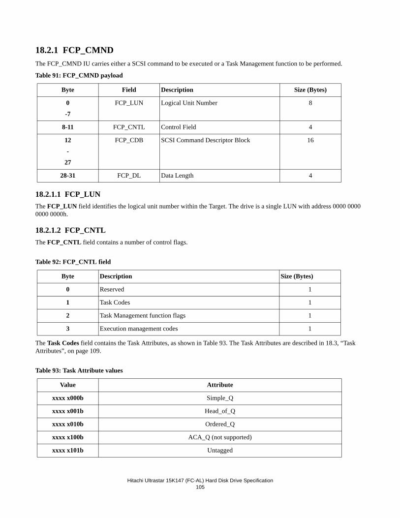
Hitachi Ultrastar 15K147 (FC-AL) Hard Disk Drive Specification105
18.2.1 FCP_CMNDThe FCP_CMND IU carries either a SCSI command to be executed or a Task Management function to be performed.
Table 91: FCP_CMND payload
18.2.1.1 FCP_LUNThe FCP_LUN field identifies the logical unit number within the Target. The drive is a single LUN with address 0000 0000 0000 0000h.
18.2.1.2 FCP_CNTLThe FCP_CNTL field contains a number of control flags.
Table 92: FCP_CNTL field
The Task Codes field contains the Task Attributes, as shown in Table 93. The Task Attributes are described in 18.3, “Task Attributes”, on page 109.
Table 93: Task Attribute values
Byte Field Description Size (Bytes)
0
-7
FCP_LUN Logical Unit Number 8
8-11 FCP_CNTL Control Field 4
12
-
27
FCP_CDB SCSI Command Descriptor Block 16
28-31 FCP_DL Data Length 4
Byte Description Size (Bytes)
0 Reserved 1
1 Task Codes 1
2 Task Management function flags 1
3 Execution management codes 1
Value Attribute
xxxx x000b Simple_Q
xxxx x001b Head_of_Q
xxxx x010b Ordered_Q
xxxx x100b ACA_Q (not supported)
xxxx x101b Untagged
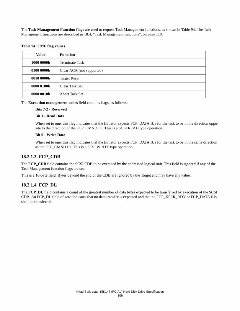
Hitachi Ultrastar 15K147 (FC-AL) Hard Disk Drive Specification106
The Task Management Function flags are used to request Task Management functions, as shown in Table 94. The Task Management functions are described in 18.4, “Task Management functions”, on page 110.
Table 94: TMF flag values
The Execution management codes field contains flags, as follows:
Bits 7-2 - Reserved
Bit 1 - Read Data
When set to one, this flag indicates that the Initiator expects FCP_DATA IUs for the task to be in the direction oppo-site to the direction of the FCP_CMND IU. This is a SCSI READ type operation.
Bit 0 - Write Data
When set to one, this flag indicates that the Initiator expects FCP_DATA IUs for the task to be in the same direction as the FCP_CMND IU. This is a SCSI WRITE type operation.
18.2.1.3 FCP_CDBThe FCP_CDB field contains the SCSI CDB to be executed by the addressed logical unit. This field is ignored if any of the Task Management function flags are set.
This is a 16-byte field. Bytes beyond the end of the CDB are ignored by the Target and may have any value.
18.2.1.4 FCP_DLThe FCP_DL field contains a count of the greatest number of data bytes expected to be transferred by execution of the SCSI CDB. An FCP_DL field of zero indicates that no data transfer is expected and that no FCP_XFER_RDY or FCP_DATA IUs shall be transferred.
Value Function
1000 0000b Terminate Task
0100 0000b Clear ACA (not supported)
0010 0000b Target Reset
0000 0100b Clear Task Set
0000 0010b Abort Task Set
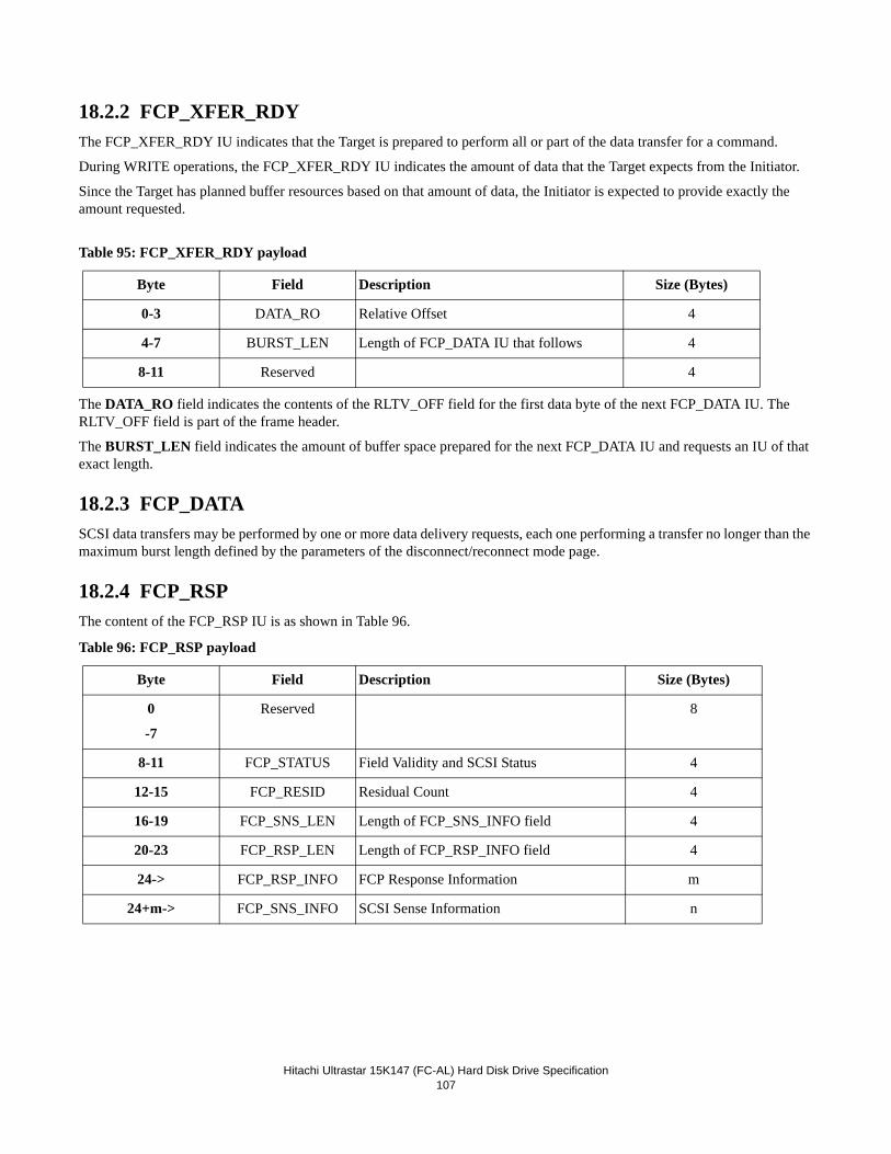
Hitachi Ultrastar 15K147 (FC-AL) Hard Disk Drive Specification107
18.2.2 FCP_XFER_RDYThe FCP_XFER_RDY IU indicates that the Target is prepared to perform all or part of the data transfer for a command.
During WRITE operations, the FCP_XFER_RDY IU indicates the amount of data that the Target expects from the Initiator.
Since the Target has planned buffer resources based on that amount of data, the Initiator is expected to provide exactly the amount requested.
Table 95: FCP_XFER_RDY payload
The DATA_RO field indicates the contents of the RLTV_OFF field for the first data byte of the next FCP_DATA IU. The RLTV_OFF field is part of the frame header.
The BURST_LEN field indicates the amount of buffer space prepared for the next FCP_DATA IU and requests an IU of that exact length.
18.2.3 FCP_DATASCSI data transfers may be performed by one or more data delivery requests, each one performing a transfer no longer than the maximum burst length defined by the parameters of the disconnect/reconnect mode page.
18.2.4 FCP_RSPThe content of the FCP_RSP IU is as shown in Table 96.
Table 96: FCP_RSP payload
Byte Field Description Size (Bytes)
0-3 DATA_RO Relative Offset 4
4-7 BURST_LEN Length of FCP_DATA IU that follows 4
8-11 Reserved 4
Byte Field Description Size (Bytes)
0
-7
Reserved 8
8-11 FCP_STATUS Field Validity and SCSI Status 4
12-15 FCP_RESID Residual Count 4
16-19 FCP_SNS_LEN Length of FCP_SNS_INFO field 4
20-23 FCP_RSP_LEN Length of FCP_RSP_INFO field 4
24-> FCP_RSP_INFO FCP Response Information m
24+m-> FCP_SNS_INFO SCSI Sense Information n
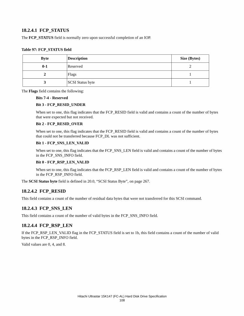
Hitachi Ultrastar 15K147 (FC-AL) Hard Disk Drive Specification108
18.2.4.1 FCP_STATUSThe FCP_STATUS field is normally zero upon successful completion of an IOP.
Table 97: FCP_STATUS field
The Flags field contains the following:
Bits 7-4 - Reserved
Bit 3 - FCP_RESID_UNDER
When set to one, this flag indicates that the FCP_RESID field is valid and contains a count of the number of bytes that were expected but not received.
Bit 2 - FCP_RESID_OVER
When set to one, this flag indicates that the FCP_RESID field is valid and contains a count of the number of bytes that could not be transferred because FCP_DL was not sufficient.
Bit 1 - FCP_SNS_LEN_VALID
When set to one, this flag indicates that the FCP_SNS_LEN field is valid and contains a count of the number of bytes in the FCP_SNS_INFO field.
Bit 0 - FCP_RSP_LEN_VALID
When set to one, this flag indicates that the FCP_RSP_LEN field is valid and contains a count of the number of bytes in the FCP_RSP_INFO field.
The SCSI Status byte field is defined in 20.0, “SCSI Status Byte”, on page 267.
18.2.4.2 FCP_RESIDThis field contains a count of the number of residual data bytes that were not transferred for this SCSI command.
18.2.4.3 FCP_SNS_LENThis field contains a count of the number of valid bytes in the FCP_SNS_INFO field.
18.2.4.4 FCP_RSP_LENIf the FCP_RSP_LEN_VALID flag in the FCP_STATUS field is set to 1b, this field contains a count of the number of valid bytes in the FCP_RSP_INFO field.
Valid values are 0, 4, and 8.
Byte Description Size (Bytes)
0-1 Reserved 2
2 Flags 1
3 SCSI Status byte 1
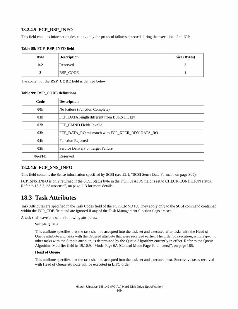
Hitachi Ultrastar 15K147 (FC-AL) Hard Disk Drive Specification109
18.2.4.5 FCP_RSP_INFOThis field contains information describing only the protocol failures detected during the execution of an IOP.
Table 98: FCP_RSP_INFO field
The content of the RSP_CODE field is defined below.
Table 99: RSP_CODE definitions
18.2.4.6 FCP_SNS_INFOThis field contains the Sense information specified by SCSI (see 22.1, “SCSI Sense Data Format”, on page 309).
FCP_SNS_INFO is only returned if the SCSI Status byte in the FCP_STATUS field is set to CHECK CONDITION status. Refer to 18.5.3, “Autosense”, on page 113 for more details.
18.3 Task AttributesTask Attributes are specified in the Task Codes field of the FCP_CMND IU. They apply only to the SCSI command contained within the FCP_CDB field and are ignored if any of the Task Management function flags are set.
A task shall have one of the following attributes:
Simple Queue
This attribute specifies that the task shall be accepted into the task set and executed after tasks with the Head of Queue attribute and tasks with the Ordered attribute that were received earlier. The order of execution, with respect to other tasks with the Simple attribute, is determined by the Queue Algorithm currently in effect. Refer to the Queue Algorithm Modifier field in 19.10.9, “Mode Page 0A (Control Mode Page Parameters)”, on page 185.
Head of Queue
This attribute specifies that the task shall be accepted into the task set and executed next. Successive tasks received with Head of Queue attribute will be executed in LIFO order.
Byte Description Size (Bytes)
0-2 Reserved 3
3 RSP_CODE 1
Code Description
00h No Failure (Function Complete)
01h FCP_DATA length different from BURST_LEN
02h FCP_CMND Fields Invalid
03h FCP_DATA_RO mismatch with FCP_XFER_RDY DATA_RO
04h Function Rejected
05h Service Delivery or Target Failure
06-FFh Reserved
Hitachi Ultrastar 15K147 (FC-AL) Hard Disk Drive Specification110
Ordered Queue
This attribute specifies that the task shall be accepted into the task set and executed in the order received. All tasks received earlier shall complete before this task. All tasks received later shall complete after this task, except for tasks received with Head of Queue attribute.
Untagged
This attribute specifies that the task shall be accepted into the task set according to the rules for an untagged task. Only one untagged task can exist for each logical unit/Initiator pair. A second untagged task for the same pair is treated as an overlapped command. SCSI-FCP commands are inherently tagged with the OXID/RXID specified in the frame header. Therefore, commands sent with the untagged task attribute are handled as if they had the Ordered Queue attribute.
Note: The uncoupled nature of FCAL makes it impossible for the drive to perform command overlap checking. (See Section 21.6.3 "Overlapped Commands")
18.4 Task Management functionsTask Management functions allow an Initiator to explicitly control the execution of one or more Tasks. SAM defines the fol-lowing:
• Abort Task (Implemented as ABTS BLS)
• Abort Task Set
• Reset LUN
• Clear ACA (not supported)
• Clear Task Set
• Target Reset
• Terminate Task
Note: The following description applies to all Task Management functions except Abort Task, which is described separately in 18.4.1, “Abort Task (Implemented as ABTS BLS)”, on page 111.
Task Management functions are transmitted in a new exchange using a T1 FCP_CMND IU (see 18.2.1, “FCP_CMND”, on page 105). The Task Management function flags in the IU specify the required function. If any flag is set, all CDB related fields of the IU are ignored (FCP_CDB, FCP_DL, the Task Codes and Execution Management fields of FCP_CNTL). Only one Task Management function flag may be set.
The Target responds to a Task Management function with an I4 FCP_RSP IU (see 18.2.4, “FCP_RSP”, on page 107). The RSP_CODE in the FCP_RSP_INFO field shall be as shown in Table 100 and all other fields shall be zeroes.
Table 100: Task Management function RSP_CODE definitions
Code Description
00h No Failure (Function Complete)
04h Function Rejected
05h Service Delivery or Target Failure
Hitachi Ultrastar 15K147 (FC-AL) Hard Disk Drive Specification111
18.4.1 Abort Task (Implemented as ABTS BLS)The Abort Task function is performed using the FC-PH link management functions. Specifically, the Abort Sequence (ABTS) Basic Link Service (BLS). Refer to 17.2.1, “Abort sequence (ABTS)”, on page 57 for a detailed description of this BLS.
Abort Task causes the Target to abort the specified task, if it exists. Previously established conditions such as Mode parameters and reservations are not affected.
The Initiator performs the Abort Task by using the FC-PH Recovery Abort Protocol. This protocol recovers any resources associated with the exchange that is being terminated.
The Initiator shall also use the recovery abort protocol for each open exchange following receipt of an FCP_RSP with a RSP_CODE of No Failure (Function Complete) to Abort Task Set, Clear Task Set, or Target Reset Task Management function.
The recovery abort protocol is as follows:
• The Initiator generates an ABTS sequence. This may be done regardless of whether or not the Initiator has sequence initiative. In the ABTS frame:
- SEQ_ID is set to the SEQ_ID of an open sequence at the Initiator. If no sequence is open, any SEQ_ID not cur-rently in use between the Initiator and the Target may be used.
- SEQ_CNT is set to one more than the SEQ_CNT of the last frame transmitted in the open sequence. If no sequence is open, SEQ_CNT is zero.
- OX_ID is set to the OX_ID assigned by the Initiator to the task that is being aborted.
- RX_ID is set to FFFFh if no FCP_XFR_RDY (WRITE) or READ data (READ) has been received from the Target. Otherwise, RX_ID is set to the RX_ID assigned by the Target to the task that is being aborted.
- F_CTL is set for Sequence Context = Initiator.
• The Target may reject the ABTS with a BA_RJT frame only if 1. the Target has assigned an RX_ID to an OX_ID in a previous frame, and2. the ABTS has an unknown OX_ID/RX_ID combination.
The reason code in the BA_RJT is Logical error and the reason code explanation is Invalid OX_ID-RX_ID combina-tion. The F_CTL field is set to indicate that this is the last frame of the exchange.
• The target accepts the ABTS with a BA_ACC frame. In the frame header:
- OX_ID is set from the OX_ID in the ABTS
- RX_ID is set from the RX_ID in the ABTS
- F_CTL is set to indicate that this is the last frame of the exchange (L_S = 1b) and Sequence Context =Recipient.
In the frame payload:
- SEQ_ID Validity is set to 00h
- SEQ_ID is ignored by the recipient and may therefore be any value
- OX_ID is set from the OX_ID in the ABTS
- RX_ID is set from the RX_ID in the ABTS
- Low SEQ_CNT is set to 0000h
- High SEQ_CNT is set to FFFFh
18.4.2 Abort Task SetAbort Task Set causes the Target to abort all tasks in the task set that were created by the Initiator. The action is equivalent to receiving a series of Abort Task requests. Previously established conditions such as Mode parameters and reservations are not affected.
Hitachi Ultrastar 15K147 (FC-AL) Hard Disk Drive Specification112
18.4.3 Terminate TaskThe drive does not support Terminate Task. An FCP_RSP with a RSP_CODE of Function Rejected will be returned.
18.4.4 Clear ACAThe drive does not support Clear ACA. An FCP_RSP with a RSP_CODE of Function Rejected will be returned.
18.4.5 Target ResetThe Target Reset Task Management function causes the Target to execute a hard reset, as defined by SAM. This means:
1. Abort all tasks for all Initiators. 2. Release any device reservation. 3. Return all internal states to their initial power-on and default values, as established by PRLI. 4. Set a unit attention condition for all Initiators.
Target Reset does not affect any login state.
18.4.6 Clear Task SetClear Task Set causes the Target to abort all tasks in the task set. The action is equivalent to receiving a series of Abort Task requests from all Initiators.
A unit attention condition shall be generated for all other Initiators with tasks in the task set. The Additional Sense Code shall be Commands cleared by another Initiator.
Previously established conditions such as Mode parameters and reservations are not affected.
18.4.7 Reset LUNThe Reset LUN Task Management function causes the drive to execute a hard reset with the same actions as Target Reset. See section 18.4.5.
18.5 Miscellaneous
18.5.1 TagsUsing SCSI-FCP, an I/O Process equates to a Fibre Channel Exchange. All IOPs are therefore implicitly tagged by the Fully Qualified Exchange ID (FQXID).
The FQXID is the 80-bit concatenation of the S_ID, D_ID, OX_ID and RX_ID from any frame in the exchange.
18.5.2 Auto-Contingent Allegiance (ACA)In parallel SCSI-2, a CHECK CONDITION generates sense data for the faulted initiator (the one that got the CHECK CON-DITION) and either suspends or aborts all commands queued by that Initiator. Execution of the next command from the faulted Initiator clears the sense data and allows queued commands to resume. This is 'Contingent Allegiance' (CA).
CA requires an interlocked interface to work. In a non-interlocked serial interface, the 'next' command could already be on its way before the faulted Initiator receives the CHECK CONDITION and sense data could be inadvertently lost.
In SCSI-3, ACA replaces the SCSI-2 Contingent Allegiance and Extended Contingent Allegiance conditions.
Hitachi Ultrastar 15K147 (FC-AL) Hard Disk Drive Specification113
ACA is a condition that is created within the Target task set whenever CHECK CONDITION is returned. While it exists, all tasks in the task set are blocked (i.e., the queue is frozen). New tasks from Initiators other than the faulted Initiator are not entered into the task set and are completed with a status of ACA ACTIVE.
New tasks from the faulted Initiator are entered into the task set under two different conditions, depending on the state of the NACA bit in the CDB Control Byte of the faulting command.
1. If the NACA bit was set to 0b, the previously described SCSI-2 CA rules apply. 2. If the NACA bit was set to 1b, the new task must have the ACA attribute and there must be no other task in the task set with the ACA attribute. If these conditions are not met, the task is completed with a status of ACA ACTIVE.
Note: Only NACA = 0b is supported.
18.5.3 AutosenseAutosense is the automatic return of sense data upon completion of the task. It is equivalent to an explicit REQUEST SENSE command being executed immediately after Check Condition status is returned.
The sense data is returned in the I4 FCP_RSP IU. The FCP_SNS_LEN field indicates how many bytes of valid sense are con-tained in the FCP_SNS_INFO field.

Hitachi Ultrastar 15K147 (FC-AL) Hard Disk Drive Specification114
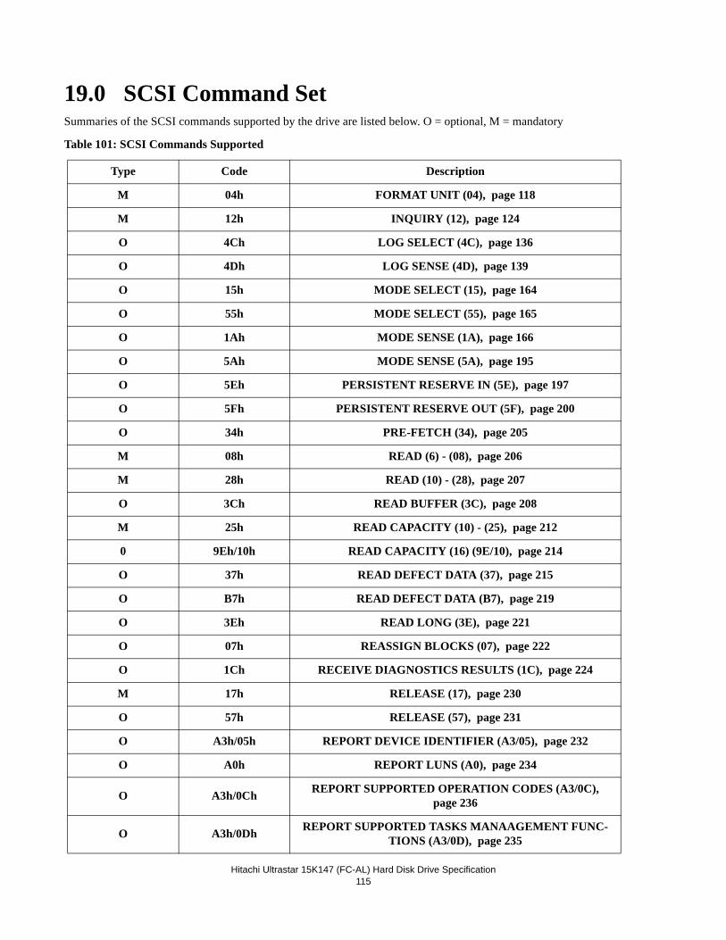
Hitachi Ultrastar 15K147 (FC-AL) Hard Disk Drive Specification
115
19.0 SCSI Command SetSummaries of the SCSI commands supported by the drive are listed below. O = optional, M = mandatory
Table 101: SCSI Commands Supported
Type Code Description
M 04h FORMAT UNIT (04), page 118
M 12h INQUIRY (12), page 124
O 4Ch LOG SELECT (4C), page 136
O 4Dh LOG SENSE (4D), page 139
O 15h MODE SELECT (15), page 164
O 55h MODE SELECT (55), page 165
O 1Ah MODE SENSE (1A), page 166
O 5Ah MODE SENSE (5A), page 195
O 5Eh PERSISTENT RESERVE IN (5E), page 197
O 5Fh PERSISTENT RESERVE OUT (5F), page 200
O 34h PRE-FETCH (34), page 205
M 08h READ (6) - (08), page 206
M 28h READ (10) - (28), page 207
O 3Ch READ BUFFER (3C), page 208
M 25h READ CAPACITY (10) - (25), page 212
0 9Eh/10h READ CAPACITY (16) (9E/10), page 214
O 37h READ DEFECT DATA (37), page 215
O B7h READ DEFECT DATA (B7), page 219
O 3Eh READ LONG (3E), page 221
O 07h REASSIGN BLOCKS (07), page 222
O 1Ch RECEIVE DIAGNOSTICS RESULTS (1C), page 224
M 17h RELEASE (17), page 230
O 57h RELEASE (57), page 231
O A3h/05h REPORT DEVICE IDENTIFIER (A3/05), page 232
O A0h REPORT LUNS (A0), page 234
O A3h/0Ch REPORT SUPPORTED OPERATION CODES (A3/0C), page 236
O A3h/0Dh REPORT SUPPORTED TASKS MANAAGEMENT FUNC-TIONS (A3/0D), page 235
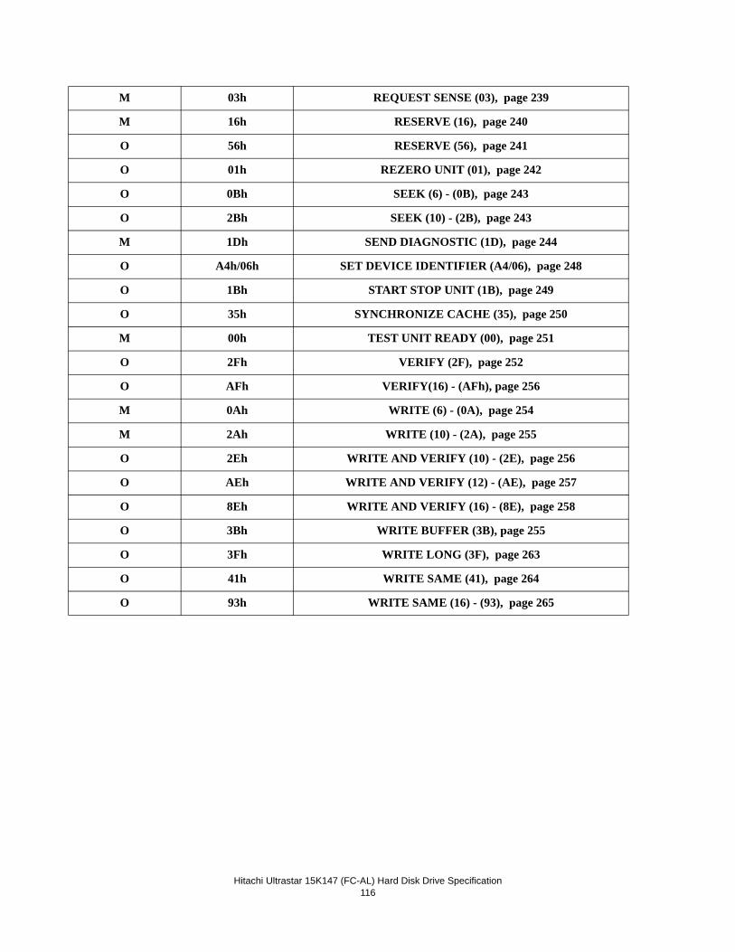
Hitachi Ultrastar 15K147 (FC-AL) Hard Disk Drive Specification
116
M 03h REQUEST SENSE (03), page 239
M 16h RESERVE (16), page 240
O 56h RESERVE (56), page 241
O 01h REZERO UNIT (01), page 242
O 0Bh SEEK (6) - (0B), page 243
O 2Bh SEEK (10) - (2B), page 243
M 1Dh SEND DIAGNOSTIC (1D), page 244
O A4h/06h SET DEVICE IDENTIFIER (A4/06), page 248
O 1Bh START STOP UNIT (1B), page 249
O 35h SYNCHRONIZE CACHE (35), page 250
M 00h TEST UNIT READY (00), page 251
O 2Fh VERIFY (2F), page 252
O AFh VERIFY(16) - (AFh), page 256
M 0Ah WRITE (6) - (0A), page 254
M 2Ah WRITE (10) - (2A), page 255
O 2Eh WRITE AND VERIFY (10) - (2E), page 256
O AEh WRITE AND VERIFY (12) - (AE), page 257
O 8Eh WRITE AND VERIFY (16) - (8E), page 258
O 3Bh WRITE BUFFER (3B), page 255
O 3Fh WRITE LONG (3F), page 263
O 41h WRITE SAME (41), page 264
O 93h WRITE SAME (16) - (93), page 265
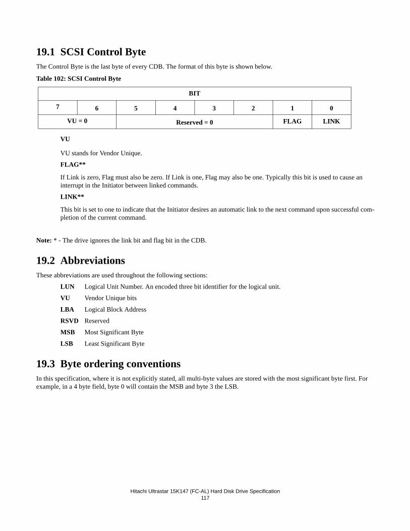
Hitachi Ultrastar 15K147 (FC-AL) Hard Disk Drive Specification
117
19.1 SCSI Control ByteThe Control Byte is the last byte of every CDB. The format of this byte is shown below.
Table 102: SCSI Control Byte
VU
VU stands for Vendor Unique.
FLAG**
If Link is zero, Flag must also be zero. If Link is one, Flag may also be one. Typically this bit is used to cause an interrupt in the Initiator between linked commands.
LINK**
This bit is set to one to indicate that the Initiator desires an automatic link to the next command upon successful com-pletion of the current command.
Note: * - The drive ignores the link bit and flag bit in the CDB.
19.2 AbbreviationsThese abbreviations are used throughout the following sections:
LUN Logical Unit Number. An encoded three bit identifier for the logical unit.
VU Vendor Unique bits
LBA Logical Block Address
RSVD Reserved
MSB Most Significant Byte
LSB Least Significant Byte
19.3 Byte ordering conventionsIn this specification, where it is not explicitly stated, all multi-byte values are stored with the most significant byte first. For example, in a 4 byte field, byte 0 will contain the MSB and byte 3 the LSB.
BIT
7 6 5 4 3 2 1 0
VU = 0 Reserved = 0 FLAG LINK
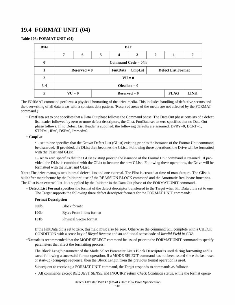
Hitachi Ultrastar 15K147 (FC-AL) Hard Disk Drive Specification
118
19.4 FORMAT UNIT (04)Table 103: FORMAT UNIT (04)
The FORMAT command performs a physical formatting of the drive media. This includes handling of defective sectors and the overwriting of all data areas with a constant data pattern. (Reserved areas of the media are not affected by the FORMAT command.)
• FmtData set to one specifies that a Data Out phase follows the Command phase. The Data Out phase consists of a defect list header followed by zero or more defect descriptors, the Glist. FmtData set to zero specifies that no Data Out phase follows. If no Defect List Header is supplied, the following defaults are assumed: DPRY=0, DCRT=1, STPF=1, IP=0, DSP=0, Immed=0.
• CmpLst • - set to one specifies that the Grown Defect List (GList) existing prior to the issuance of the Format Unit command be discarded. If provided, the DList then becomes the GList. Following these operations, the Drive will be formatted with the PList and GList.• - set to zero specifies that the GList existing prior to the issuance of the Format Unit command is retained. If pro-vided, the DList is combined with the GList to become the new GList. Following these operations, the Drive will be formatted with the PList and GList.
Note: The drive manages two internal defect lists and one external. The Plist is created at time of manufacture. The Glist is built after manufacture by the Initiators’ use of the REASSIGN BLOCK command and the Automatic Reallocate functions. The Dlist is an external list. It is supplied by the Initiator in the Data Out phase of the FORMAT UNIT command.
• Defect List Format specifies the format of the defect descriptor transferred to the Target when FmtData bit is set to one. The Target supports the following three defect descriptor formats for the FORMAT UNIT command:
Format Description
000b Block format
100b Bytes From Index format
101b Physical Sector format
If the FmtData bit is set to zero, this field must also be zero. Otherwise the command will complete with a CHECK CONDITION with a sense key of Illegal Request and an additional sense code of Invalid Field in CDB.
•Notes:It is recommended that the MODE SELECT command be issued prior to the FORMAT UNIT command to specify parameters that affect the formatting process.
The Block Length parameter of the Mode Select Parameter List’s Block Descriptor is used during formatting and is saved following a successful format operation. If a MODE SELECT command has not been issued since the last reset or start-up (bring-up) sequence, then the Block Length from the previous format operation is used.
Subsequent to receiving a FORMAT UNIT command, the Target responds to commands as follows:
- All commands except REQUEST SENSE and INQUIRY return Check Condition status, while the format opera-
Byte BIT
7 6 5 4 3 2 1 0
0 Command Code = 04h
1 Reserved = 0 FmtData CmpLst Defect List Format
2 VU = 0
3-4 Obsolete = 0
5 VU = 0 Reserved = 0 FLAG LINK
Hitachi Ultrastar 15K147 (FC-AL) Hard Disk Drive Specification
119
tion is an active I/O process.
- When tagged queuing is enabled (DQue = 0), all commands except REQUEST SENSE and INQUIRY return Queue Full status, while the FORMAT UNIT command is a queued I/O process.
- When tagged queuing is disabled (DQue = 1), all commands except REQUEST SENSE and INQUIRY return Busy status, while the FORMAT UNIT command is a queued I/O process
- If a REQUEST SENSE command is received while a format operation is an active I/O process, the Target returns Good status. The sense key is set to Not Ready and the additional sense code and qualifier is set to Format In Progress.
- If an INQUIRY command is received while a format operation is an active I/O process, the Target returns Good status and Inquiry data as requested.
The format operation must complete successfully for the Drive to be usable. If the command is interrupted by a reset, power down, or an unrecoverable error, the Drive enters a degraded mode of operation in which reading and writing are prohibited. To exit the degraded mode, another FORMAT UNIT command must be sent by the Initiator and com-pleted successfully by the Target.
The FORMAT UNIT command sets the Unit Attention Condition for all Initiators except the one that issued the FORMAT UNIT command.
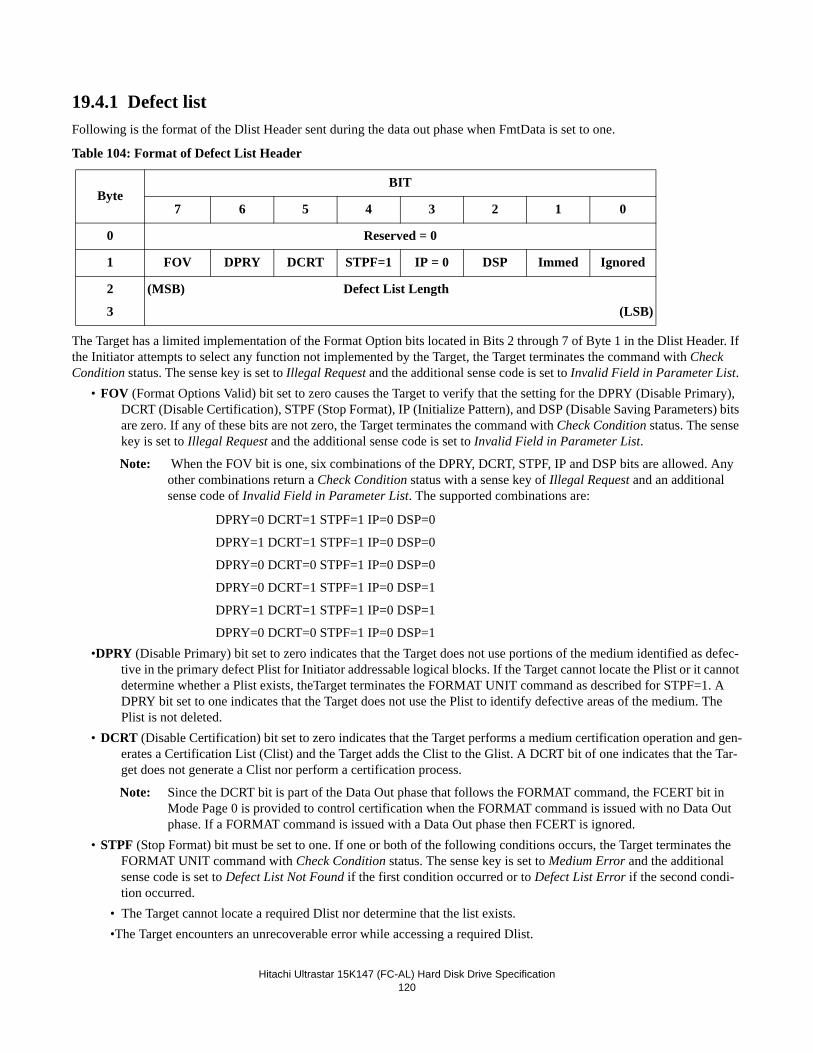
Hitachi Ultrastar 15K147 (FC-AL) Hard Disk Drive Specification
120
19.4.1 Defect listFollowing is the format of the Dlist Header sent during the data out phase when FmtData is set to one.
Table 104: Format of Defect List Header
The Target has a limited implementation of the Format Option bits located in Bits 2 through 7 of Byte 1 in the Dlist Header. If the Initiator attempts to select any function not implemented by the Target, the Target terminates the command with Check Condition status. The sense key is set to Illegal Request and the additional sense code is set to Invalid Field in Parameter List.
• FOV (Format Options Valid) bit set to zero causes the Target to verify that the setting for the DPRY (Disable Primary), DCRT (Disable Certification), STPF (Stop Format), IP (Initialize Pattern), and DSP (Disable Saving Parameters) bits are zero. If any of these bits are not zero, the Target terminates the command with Check Condition status. The sense key is set to Illegal Request and the additional sense code is set to Invalid Field in Parameter List.
Note: When the FOV bit is one, six combinations of the DPRY, DCRT, STPF, IP and DSP bits are allowed. Any other combinations return a Check Condition status with a sense key of Illegal Request and an additional sense code of Invalid Field in Parameter List. The supported combinations are:
DPRY=0 DCRT=1 STPF=1 IP=0 DSP=0
DPRY=1 DCRT=1 STPF=1 IP=0 DSP=0
DPRY=0 DCRT=0 STPF=1 IP=0 DSP=0
DPRY=0 DCRT=1 STPF=1 IP=0 DSP=1
DPRY=1 DCRT=1 STPF=1 IP=0 DSP=1
DPRY=0 DCRT=0 STPF=1 IP=0 DSP=1•DPRY (Disable Primary) bit set to zero indicates that the Target does not use portions of the medium identified as defec-
tive in the primary defect Plist for Initiator addressable logical blocks. If the Target cannot locate the Plist or it cannot determine whether a Plist exists, theTarget terminates the FORMAT UNIT command as described for STPF=1. A DPRY bit set to one indicates that the Target does not use the Plist to identify defective areas of the medium. The Plist is not deleted.
• DCRT (Disable Certification) bit set to zero indicates that the Target performs a medium certification operation and gen-erates a Certification List (Clist) and the Target adds the Clist to the Glist. A DCRT bit of one indicates that the Tar-get does not generate a Clist nor perform a certification process.
Note: Since the DCRT bit is part of the Data Out phase that follows the FORMAT command, the FCERT bit in Mode Page 0 is provided to control certification when the FORMAT command is issued with no Data Out phase. If a FORMAT command is issued with a Data Out phase then FCERT is ignored.
• STPF (Stop Format) bit must be set to one. If one or both of the following conditions occurs, the Target terminates the FORMAT UNIT command with Check Condition status. The sense key is set to Medium Error and the additional sense code is set to Defect List Not Found if the first condition occurred or to Defect List Error if the second condi-tion occurred.
• The Target cannot locate a required Dlist nor determine that the list exists. •The Target encounters an unrecoverable error while accessing a required Dlist.
ByteBIT
7 6 5 4 3 2 1 0
0 Reserved = 0
1 FOV DPRY DCRT STPF=1 IP = 0 DSP Immed Ignored
2
3
(MSB) Defect List Length
(LSB)
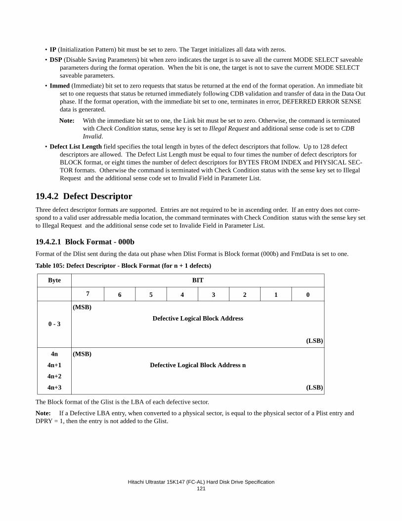
Hitachi Ultrastar 15K147 (FC-AL) Hard Disk Drive Specification
121
• IP (Initialization Pattern) bit must be set to zero. The Target initializes all data with zeros. • DSP (Disable Saving Parameters) bit when zero indicates the target is to save all the current MODE SELECT saveable
parameters during the format operation. When the bit is one, the target is not to save the current MODE SELECT saveable parameters.
• Immed (Immediate) bit set to zero requests that status be returned at the end of the format operation. An immediate bit set to one requests that status be returned immediately following CDB validation and transfer of data in the Data Out phase. If the format operation, with the immediate bit set to one, terminates in error, DEFERRED ERROR SENSE data is generated.
Note: With the immediate bit set to one, the Link bit must be set to zero. Otherwise, the command is terminated with Check Condition status, sense key is set to Illegal Request and additional sense code is set to CDB Invalid.
• Defect List Length field specifies the total length in bytes of the defect descriptors that follow. Up to 128 defect descriptors are allowed. The Defect List Length must be equal to four times the number of defect descriptors for BLOCK format, or eight times the number of defect descriptors for BYTES FROM INDEX and PHYSICAL SEC-TOR formats. Otherwise the command is terminated with Check Condition status with the sense key set to Illegal Request and the additional sense code set to Invalid Field in Parameter List.
19.4.2 Defect DescriptorThree defect descriptor formats are supported. Entries are not required to be in ascending order. If an entry does not corre-spond to a valid user addressable media location, the command terminates with Check Condition status with the sense key set to Illegal Request and the additional sense code set to Invalide Field in Parameter List.
19.4.2.1 Block Format - 000bFormat of the Dlist sent during the data out phase when Dlist Format is Block format (000b) and FmtData is set to one.
Table 105: Defect Descriptor - Block Format (for n + 1 defects)
The Block format of the Glist is the LBA of each defective sector.
Note: If a Defective LBA entry, when converted to a physical sector, is equal to the physical sector of a Plist entry and DPRY = 1, then the entry is not added to the Glist.
Byte BIT
7 6 5 4 3 2 1 0
0 - 3
(MSB)
Defective Logical Block Address
(LSB)
4n
4n+1
4n+2
4n+3
(MSB)
Defective Logical Block Address n
(LSB)
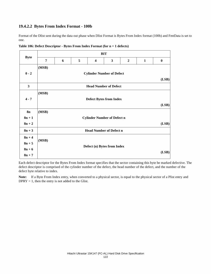
Hitachi Ultrastar 15K147 (FC-AL) Hard Disk Drive Specification
122
19.4.2.2 Bytes From Index Format - 100b
Format of the Dlist sent during the data out phase when Dlist Format is Bytes From Index format (100b) and FmtData is set to one.
Table 106: Defect Descriptor - Bytes From Index Format (for n = 1 defects)
Each defect descriptor for the Bytes From Index format specifies that the sector containing this byte be marked defective. The defect descriptor is comprised of the cylinder number of the defect, the head number of the defect, and the number of the defect byte relative to index.
Note: If a Byte From Index entry, when converted to a physical sector, is equal to the physical sector of a Plist entry and DPRY = 1, then the entry is not added to the Glist.
ByteBIT
7 6 5 4 3 2 1 0
0 - 2
(MSB)
Cylinder Number of Defect
(LSB)
3 Head Number of Defect
4 - 7
(MSB)
Defect Bytes from Index
(LSB)
8n
8n + 1
8n + 2
(MSB)
Cylinder Number of Defect n
(LSB)
8n + 3 Head Number of Defect n
8n + 4
8n + 5
8n + 6
8n + 7
(MSB)
Defect (n) Bytes from Index
(LSB)
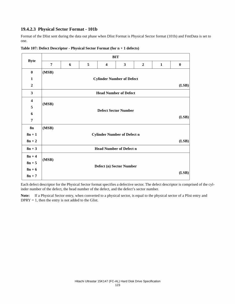
Hitachi Ultrastar 15K147 (FC-AL) Hard Disk Drive Specification
123
19.4.2.3 Physical Sector Format - 101bFormat of the Dlist sent during the data out phase when Dlist Format is Physical Sector format (101b) and FmtData is set to one.
Table 107: Defect Descriptor - Physical Sector Format (for n + 1 defects)
Each defect descriptor for the Physical Sector format specifies a defective sector. The defect descriptor is comprised of the cyl-inder number of the defect, the head number of the defect, and the defect’s sector number.
Note: If a Physical Sector entry, when converted to a physical sector, is equal to the physical sector of a Plist entry and DPRY = 1, then the entry is not added to the Glist.
ByteBIT
7 6 5 4 3 2 1 0
0
1
2
(MSB)
Cylinder Number of Defect
(LSB)
3 Head Number of Defect
4
5
6
7
(MSB)
Defect Sector Number
(LSB)
8n
8n + 1
8n + 2
(MSB)
Cylinder Number of Defect n
(LSB)
8n + 3 Head Number of Defect n
8n + 4
8n + 5
8n + 6
8n + 7
(MSB)
Defect (n) Sector Number
(LSB)
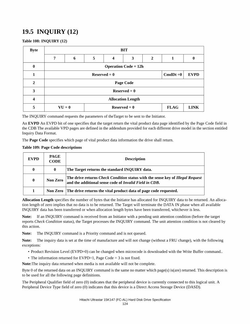
Hitachi Ultrastar 15K147 (FC-AL) Hard Disk Drive Specification
124
19.5 INQUIRY (12)Table 108: INQUIRY (12)
The INQUIRY command requests the parameters of theTarget to be sent to the Initiator.
An EVPD An EVPD bit of one specifies that the target return the vital product data page identified by the Page Code field in the CDB The available VPD pages are defined in the addendum provided for each different drive model in the section entitled Inquiry Data Format.
The Page Code specifies which page of vital product data information the drive shall return.
Table 109: Page Code descriptions
Allocation Length specifies the number of bytes that the Initiator has allocated for INQUIRY data to be returned. An alloca-tion length of zero implies that no data is to be returned. The Target will terminate the DATA IN phase when all available INQUIRY data has been transferred or when allocation length bytes have been transferred, whichever is less.
Note: If an INQUIRY command is received from an Initiator with a pending unit attention condition (before the target reports Check Condition status), the Target processes the INQUIRY command. The unit attention condition is not cleared by this action.
Note: The INQUIRY command is a Priority command and is not queued.
Note: The inquiry data is set at the time of manufacture and will not change (without a FRU change), with the following exceptions:
• Product Revision Level (EVPD=0) can be changed when microcode is downloaded with the Write Buffer command.. • The information returned for EVPD=1, Page Code = 3 is not fixed.
Note:The inquiry data returned when media is not available will not be complete.Byte 0 of the returned data on an INQUIRY command is the same no matter which page(s) is(are) returned. This description is to be used for all the following page definitions.
The Peripheral Qualifier field of zero (0) indicates that the peripheral device is currently connected to this logical unit. A Peripheral Device Type field of zero (0) indicates that this device is a Direct Access Storage Device (DASD).
Byte BIT
7 6 5 4 3 2 1 0
0 Operation Code = 12h
1 Reserved = 0 CmdDt =0 EVPD
2 Page Code
3 Reserved = 0
4 Allocation Length
5 VU = 0 Reserved = 0 FLAG LINK
EVPD PAGE CODE Description
0 0 The Target returns the standard INQUIRY data.
0 Non Zero The drive returns Check Condition status with the sense key of Illegal Request and the additional sense code of Invalid Field in CDB.
1 Non Zero The drive returns the vital product data of page code requested.
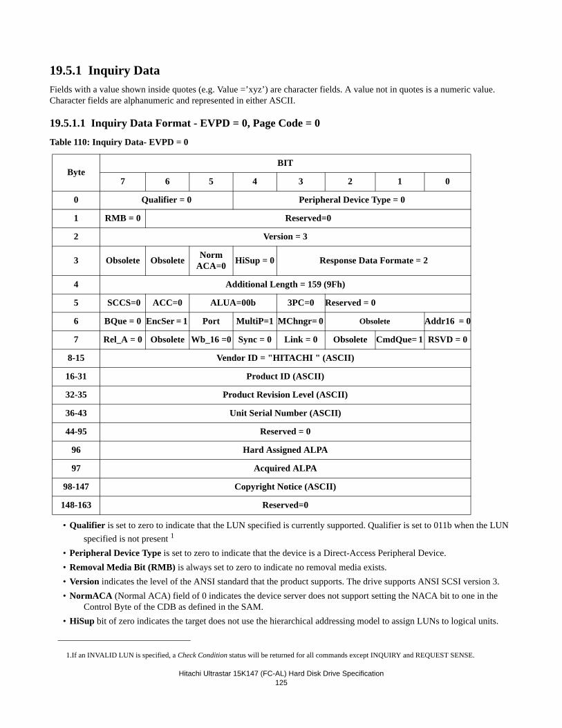
Hitachi Ultrastar 15K147 (FC-AL) Hard Disk Drive Specification
125
19.5.1 Inquiry DataFields with a value shown inside quotes (e.g. Value =’xyz’) are character fields. A value not in quotes is a numeric value. Character fields are alphanumeric and represented in either ASCII.
19.5.1.1 Inquiry Data Format - EVPD = 0, Page Code = 0
Table 110: Inquiry Data- EVPD = 0
• Qualifier is set to zero to indicate that the LUN specified is currently supported. Qualifier is set to 011b when the LUN specified is not present 1
• Peripheral Device Type is set to zero to indicate that the device is a Direct-Access Peripheral Device.• Removal Media Bit (RMB) is always set to zero to indicate no removal media exists. • Version indicates the level of the ANSI standard that the product supports. The drive supports ANSI SCSI version 3. • NormACA (Normal ACA) field of 0 indicates the device server does not support setting the NACA bit to one in the
Control Byte of the CDB as defined in the SAM. • HiSup bit of zero indicates the target does not use the hierarchical addressing model to assign LUNs to logical units.
ByteBIT
7 6 5 4 3 2 1 0
0 Qualifier = 0 Peripheral Device Type = 0
1 RMB = 0 Reserved=0
2 Version = 3
3 Obsolete Obsolete Norm ACA=0 HiSup = 0 Response Data Formate = 2
4 Additional Length = 159 (9Fh)
5 SCCS=0 ACC=0 ALUA=00b 3PC=0 Reserved = 0
6 BQue = 0 EncSer = 1 Port MultiP=1 MChngr= 0 Obsolete Addr16 = 0
7 Rel_A = 0 Obsolete Wb_16 =0 Sync = 0 Link = 0 Obsolete CmdQue= 1 RSVD = 0
8-15 Vendor ID = "HITACHI " (ASCII)
16-31 Product ID (ASCII)
32-35 Product Revision Level (ASCII)
36-43 Unit Serial Number (ASCII)
44-95 Reserved = 0
96 Hard Assigned ALPA
97 Acquired ALPA
98-147 Copyright Notice (ASCII)
148-163 Reserved=0
1.If an INVALID LUN is specified, a Check Condition status will be returned for all commands except INQUIRY and REQUEST SENSE.
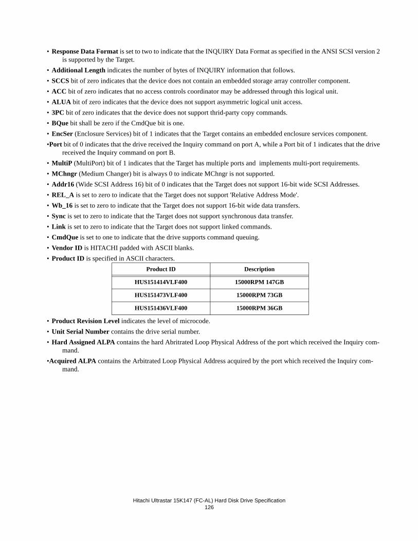
Hitachi Ultrastar 15K147 (FC-AL) Hard Disk Drive Specification
126
• Response Data Format is set to two to indicate that the INQUIRY Data Format as specified in the ANSI SCSI version 2 is supported by the Target.
• Additional Length indicates the number of bytes of INQUIRY information that follows. • SCCS bit of zero indicates that the device does not contain an embedded storage array controller component.• ACC bit of zero indicates that no access controls coordinator may be addressed through this logical unit.• ALUA bit of zero indicates that the device does not support asymmetric logical unit access.• 3PC bit of zero indicates that the device does not support thrid-party copy commands.• BQue bit shall be zero if the CmdQue bit is one.• EncSer (Enclosure Services) bit of 1 indicates that the Target contains an embedded enclosure services component. •Port bit of 0 indicates that the drive received the Inquiry command on port A, while a Port bit of 1 indicates that the drive
received the Inquiry command on port B.• MultiP (MultiPort) bit of 1 indicates that the Target has multiple ports and implements multi-port requirements. • MChngr (Medium Changer) bit is always 0 to indicate MChngr is not supported. • Addr16 (Wide SCSI Address 16) bit of 0 indicates that the Target does not support 16-bit wide SCSI Addresses. • REL_A is set to zero to indicate that the Target does not support 'Relative Address Mode'. • Wb_16 is set to zero to indicate that the Target does not support 16-bit wide data transfers.• Sync is set to zero to indicate that the Target does not support synchronous data transfer.• Link is set to zero to indicate that the Target does not support linked commands. • CmdQue is set to one to indicate that the drive supports command queuing. • Vendor ID is HITACHI padded with ASCII blanks. • Product ID is specified in ASCII characters.
• Product Revision Level indicates the level of microcode.• Unit Serial Number contains the drive serial number.• Hard Assigned ALPA contains the hard Abritrated Loop Physical Address of the port which received the Inquiry com-
mand. •Acquired ALPA contains the Arbitrated Loop Physical Address acquired by the port which received the Inquiry com-
mand.
Product ID Description
HUS151414VLF400 15000RPM 147GB
HUS151473VLF400 15000RPM 73GB
HUS151436VLF400 15000RPM 36GB
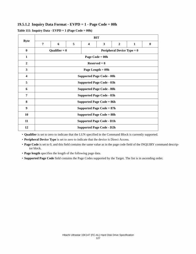
Hitachi Ultrastar 15K147 (FC-AL) Hard Disk Drive Specification
127
19.5.1.2 Inquiry Data Format - EVPD = 1 - Page Code = 00hTable 111: Inquiry Data - EVPD = 1 (Page Code = 00h)
• Qualifier is set to zero to indicate that the LUN specified in the Command Block is currently supported. • Peripheral Device Type is set to zero to indicate that the device is Direct Access. • Page Code is set to 0, and this field contains the same value as in the page code field of the INQUIRY command descrip-
tor block. • Page length specifies the length of the following page data. • Supported Page Code field contains the Page Codes supported by the Target. The list is in ascending order.
ByteBIT
7 6 5 4 3 2 1 0
0 Qualifier = 0 Peripheral Device Type = 0
1 Page Code = 00h
2 Reserved = 0
3 Page Length = 09h
4 Supported Page Code - 00h
5 Supported Page Code - 03h
6 Supported Page Code - 80h
7 Supported Page Code - 83h
8 Supported Page Code = 86h
9 Supported Page Code = 87h
10 Supported Page Code = 88h
11 Supported Page Code - D1h
12 Supported Page Code - D2h
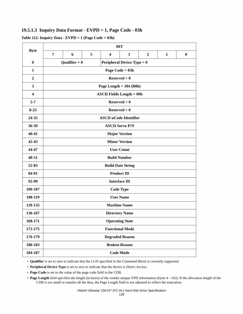
Hitachi Ultrastar 15K147 (FC-AL) Hard Disk Drive Specification
128
19.5.1.3 Inquiry Data Format - EVPD = 1, Page Code - 03hTable 112: Inquiry Data - EVPD = 1 (Page Code = 03h)
• Qualifier is set to zero to indicate that the LUN specified in the Command Block is currently supported.• Peripheral Device Type is set to zero to indicate that the device is Direct Access.• Page Code is set to the value of the page code field in the CDB.• Page Length field specifies the length (in bytes) of the vendor unique VPD information (bytes 4 - 163). If the allocation length of the
CDB is too small to transfer all the data, the Page Length field is not adjusted to reflect the truncation.
ByteBIT
7 6 5 4 3 2 1 0
0 Qualifier = 0 Peripheral Device Type = 0
1 Page Code = 03h
2 Reserved = 0
3 Page Length = 184 (B8h)
4 ASCII Fields Length = 00h
5-7 Reserved = 0
8-23 Reserved = 0
24-35 ASCII uCode Identifier
36-39 ASCII Servo P/N
40-41 Major Version
42-43 Minor Version
44-47 User Count
48-51 Build Number
52-83 Build Date String
84-91 Product ID
92-99 Interface ID
100-107 Code Type
108-119 User Name
120-135 Machine Name
136-167 Directory Name
168-171 Operating State
172-175 Functional Mode
176-179 Degraded Reason
180-183 Broken Reason
184-187 Code Mode
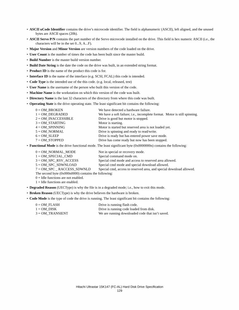
Hitachi Ultrastar 15K147 (FC-AL) Hard Disk Drive Specification
129
• ASCII uCode Identifier contains the drive’s microcode identifier. The field is alphanumeric (ASCII), left aligned, and the unused bytes are ASCII spaces (20h).
• ASCII Servo P/N contains the part number of the Servo microcode installed on the drive. This field is hex numeric ASCII (i.e., the characters will be in the set 0...9, A...F).
• Major Version and Minor Version are version numbers of the code loaded on the drive.• User Count is the number of times the code has been built since the master build.• Build Number is the master build version number.• Build Date String is the date the code on the drive was built, in an extended string format.• Product ID is the name of the product this code is for.• Interface ID is the name of the interface (e.g. SCSI, FCAL) this code is intended.• Code Type is the intended use of the this code. (e.g. local, released, test)• User Name is the username of the person who built this version of the code.• Machine Name is the workstation on which this version of the code was built.• Directory Name is the last 32 characters of the directory from where this code was built.• Operating State is the drive operating state. The least significant bit contains the following:
0 = OM_BROKEN We have detected a hardware failure.1 = OM_DEGRADED We have a soft failure; i.e., incomplete format. Motor is still spinning.2 = OM_INACCESSIBLE Drive is good but motor is stopped.3 = OM_STARTING Motor is starting.4 = OM_SPINNING Motor is started but reserved area is not loaded yet.5 = OM_NORMAL Drive is spinning and ready to read/write.6 = OM_SLEEP Drive is ready but has entered power save mode.7 = OM_STOPPED Drive has come ready but now has been stopped.
• Functional Mode is the drive functional mode. The least significant byte (0x0000000n) contains the following:
0 = OM_NORMAL_MODE Not in special or recovery mode. 1 = OM_SPECIAL_CMD Special command mode on.3 = OM_SPC_RSV_ACCESS Special cmd mode and access to reserved area allowed.5 = OM_SPC_SDWNLOAD Special cmd mode and special download allowed.7 = OM_SPC _ RACCESS_SDWNLD Special cmd, access to reserved area, and special download allowed.The second byte (0x000n0000) contains the following:0 = Idle functions are not enabled.1 = Idle functions are enabled.
• Degraded Reason (UECType) is why the file is in a degraded mode; i.e., how to exit this mode.• Broken Reason (UECType) is why the drive believes the hardware is broken. • Code Mode is the type of code the drive is running. The least significant bit contains the following:
0 = OM_FLASH Drive is running flash code.1 = OM_DISK Drive is running code loaded from disk.3 = OM_TRANSIENT We are running downloaded code that isn’t saved.
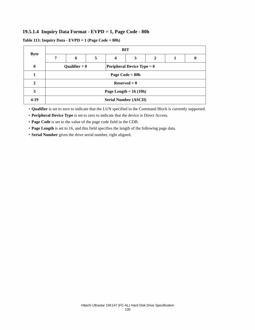
Hitachi Ultrastar 15K147 (FC-AL) Hard Disk Drive Specification
130
19.5.1.4 Inquiry Data Format - EVPD = 1, Page Code - 80h
Table 113: Inquiry Data - EVPD = 1 (Page Code = 80h)
• Qualifier is set to zero to indicate that the LUN specified in the Command Block is currently supported.• Peripheral Device Type is set to zero to indicate that the device is Direct Access.• Page Code is set to the value of the page code field in the CDB.• Page Length is set to 16, and this field specifies the length of the following page data.• Serial Number gives the drive serial number, right aligned.
ByteBIT
7 6 5 4 3 2 1 0
0 Qualifier = 0 Peripheral Device Type = 0
1 Page Code = 80h
2 Reserved = 0
3 Page Length = 16 (10h)
4-19 Serial Number (ASCII)
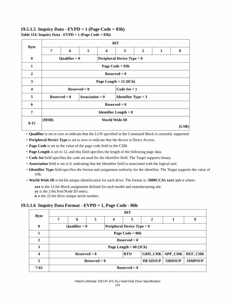
Hitachi Ultrastar 15K147 (FC-AL) Hard Disk Drive Specification
131
19.5.1.5 Inquiry Data - EVPD = 1 (Page Code = 83h)
• Qualifier is set to zero to indicate that the LUN specified in the Command Block is currently supported.• Peripheral Device Type is set to zero to indicate that the device is Direct Access.• Page Code is set to the value of the page code field in the CDB.• Page Length is set to 12, and this field specifies the length of the following page data.• Code Set field specifies the code set used for the identifier field. The Target supports binary.• Association field is set to 0, indicating that the Identifier field is associated with the logical unit. • Identifier Type field specifies the format and assignment authority for the identifier. The Target supports the value of
03h.• World Wide ID is 64-bit unique identification for each drive. The format is: 5000CCAh xxxh yyb n where:
xxx is the 12-bit Block assignment defined for each model and manufacturing site.yy is the 2-bit Port/Node ID select.n is the 22-bit drive unique serial number.
19.5.1.6 Inquiry Data Format - EVPD = 1, Page Code - 86h
Table 114: Inquiry Data - EVPD = 1 (Page Code = 83h)
ByteBIT
7 6 5 4 3 2 1 0
0 Qualifier = 0 Peripheral Device Type = 0
1 Page Code = 83h
2 Reserved = 0
3 Page Length = 12 (0Ch)
4 Reserved = 0 Code Set = 1
5 Reserved = 0 Association = 0 Identifier Type = 3
6 Reserved = 0
7 Identifier Length = 8
8-15(MSB) World Wide ID
(LSB)
ByteBIT
7 6 5 4 3 2 1 0
0 Qualifier = 0 Peripheral Device Type = 0
1 Page Code = 86h
2 Reserved = 0
3 Page Length = 60 (3Ch)
4 Reserved = 0 RTO GRD_CHK APP_CHK REF_CHK
5 Reserved = 0 HEADSUP ORDSUP SIMPSUP
7-63 Reserved = 0
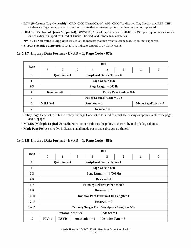
Hitachi Ultrastar 15K147 (FC-AL) Hard Disk Drive Specification
132
• RTO (Reference Tag Ownership), GRD_CHK (Guard Check), APP_CHK (Application Tag Check), and REF_CHK (Reference Tag Check) are set to zero to indicate that end-to-end protection features are not supported.
• HEADSUP (Head of Queue Supported), ORDSUP (Ordered Supported), and SIMPSUP (Simple Supported) are set to one to indicate support for Head of Queue, Ordered, and Simple task attributes.
• NV_SUP (Non-volatile Supported) is set to 0 to indicate that non-volatile cache features are not supported.• V_SUP (Volatile Supported) is set to 1 to indicate support of a volatile cache.
19.5.1.7 Inquiry Data Format - EVPD = 1, Page Code - 87h
• Policy Page Code set to 3Fh and Policy Subpage Code set to FFh indicate that the descriptor applies to all mode pages and subpages
• MILUS (Multiple Logical Units Share) set to one indicates the policy is sharded by multiple logical units. • Mode Page Policy set to 00b indicates that all mode pages and subpages are shared.
19.5.1.8 Inquiry Data Format - EVPD = 1, Page Code - 88h
ByteBIT
7 6 5 4 3 2 1 0
0 Qualifier = 0 Peripheral Device Type = 0
1 Page Code = 87h
2-3 Page Length = 0004h
4 Reserved=0 Policy Page Code = 3Fh
5 Policy Subpage Code = FFh
6 MILUS=1 Reserved = 0 Mode PagePolicy = 0
7 Reserved = 0
ByteBIT
7 6 5 4 3 2 1 0
0 Qualifier = 0 Peripheral Device Type = 0
1 Page Code = 88h
2-3 Page Length = 48 (0030h)
4-5 Reserved=0
6-7 Primary Relative Port = 0001h
8-9 Reserved = 0
10-11 Initiator Port Transport ID Length = 0
12-13 Reserved = 0
14-15 Primary Target Port Descriptors Length = 0Ch
16 Protocol Identifier Code Set = 1
17 PIV=1 RSVD Association = 1 Identifier Type = 3
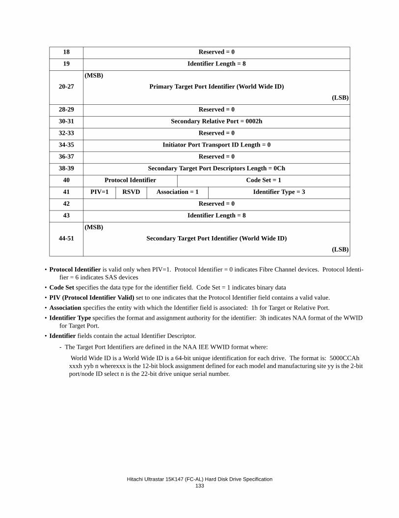
Hitachi Ultrastar 15K147 (FC-AL) Hard Disk Drive Specification
133
• Protocol Identifier is valid only when PIV=1. Protocol Identifier = 0 indicates Fibre Channel devices. Protocol Identi-fier = 6 indicates SAS devices
• Code Set specifies the data type for the identifier field. Code Set = 1 indicates binary data• PIV (Protocol Identifier Valid) set to one indicates that the Protocol Identifier field contains a valid value.• Association specifies the entity with which the Identifier field is associated: 1h for Target or Relative Port.• Identifier Type specifies the format and assignment authority for the identifier: 3h indicates NAA format of the WWID
for Target Port.• Identifier fields contain the actual Identifier Descriptor.
- The Target Port Identifiers are defined in the NAA IEE WWID format where:
World Wide ID is a World Wide ID is a 64-bit unique identification for each drive. The format is: 5000CCAh xxxh yyb n wherexxx is the 12-bit block assignment defined for each model and manufacturing site yy is the 2-bit port/node ID select n is the 22-bit drive unique serial number.
18 Reserved = 0
19 Identifier Length = 8
20-27
(MSB)
Primary Target Port Identifier (World Wide ID)
(LSB)
28-29 Reserved = 0
30-31 Secondary Relative Port = 0002h
32-33 Reserved = 0
34-35 Initiator Port Transport ID Length = 0
36-37 Reserved = 0
38-39 Secondary Target Port Descriptors Length = 0Ch
40 Protocol Identifier Code Set = 1
41 PIV=1 RSVD Association = 1 Identifier Type = 3
42 Reserved = 0
43 Identifier Length = 8
44-51
(MSB)
Secondary Target Port Identifier (World Wide ID)
(LSB)
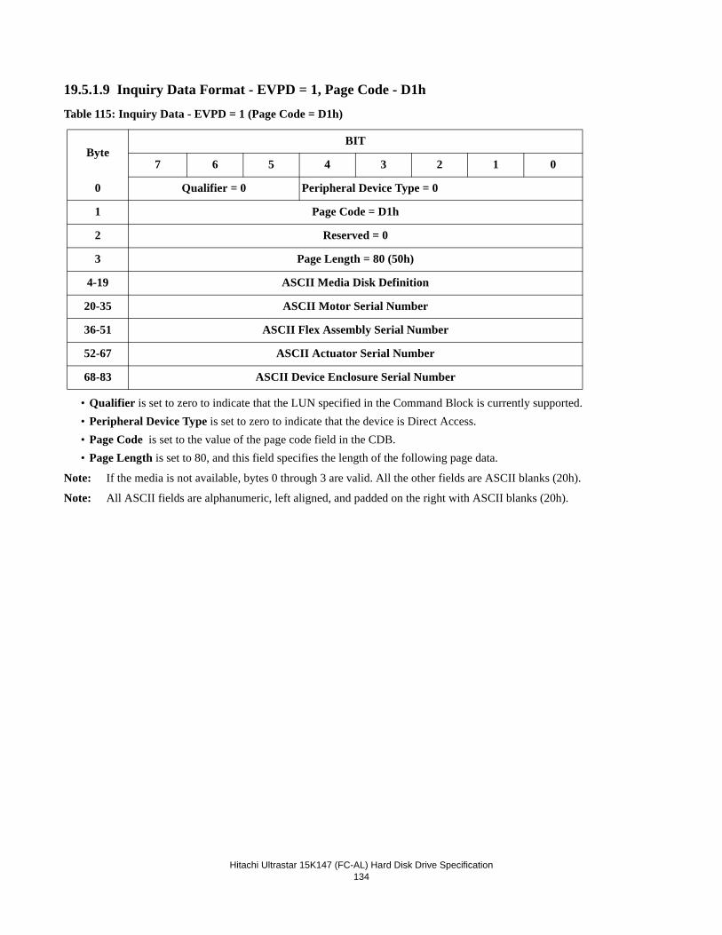
Hitachi Ultrastar 15K147 (FC-AL) Hard Disk Drive Specification
134
19.5.1.9 Inquiry Data Format - EVPD = 1, Page Code - D1h
Table 115: Inquiry Data - EVPD = 1 (Page Code = D1h)
• Qualifier is set to zero to indicate that the LUN specified in the Command Block is currently supported.• Peripheral Device Type is set to zero to indicate that the device is Direct Access.• Page Code is set to the value of the page code field in the CDB.• Page Length is set to 80, and this field specifies the length of the following page data.
Note: If the media is not available, bytes 0 through 3 are valid. All the other fields are ASCII blanks (20h).
Note: All ASCII fields are alphanumeric, left aligned, and padded on the right with ASCII blanks (20h).
ByteBIT
7 6 5 4 3 2 1 0
0 Qualifier = 0 Peripheral Device Type = 0
1 Page Code = D1h
2 Reserved = 0
3 Page Length = 80 (50h)
4-19 ASCII Media Disk Definition
20-35 ASCII Motor Serial Number
36-51 ASCII Flex Assembly Serial Number
52-67 ASCII Actuator Serial Number
68-83 ASCII Device Enclosure Serial Number
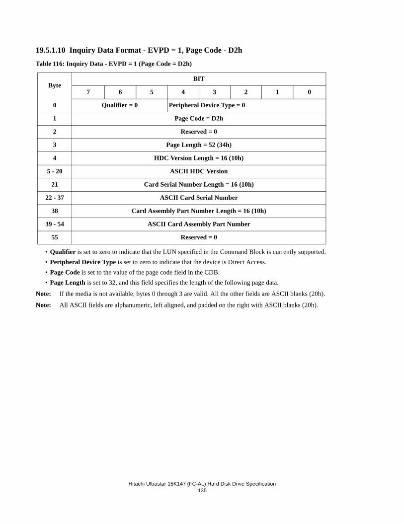
Hitachi Ultrastar 15K147 (FC-AL) Hard Disk Drive Specification
135
19.5.1.10 Inquiry Data Format - EVPD = 1, Page Code - D2h
Table 116: Inquiry Data - EVPD = 1 (Page Code = D2h)
• Qualifier is set to zero to indicate that the LUN specified in the Command Block is currently supported.• Peripheral Device Type is set to zero to indicate that the device is Direct Access.• Page Code is set to the value of the page code field in the CDB.• Page Length is set to 32, and this field specifies the length of the following page data.
Note: If the media is not available, bytes 0 through 3 are valid. All the other fields are ASCII blanks (20h).
Note: All ASCII fields are alphanumeric, left aligned, and padded on the right with ASCII blanks (20h).
ByteBIT
7 6 5 4 3 2 1 0
0 Qualifier = 0 Peripheral Device Type = 0
1 Page Code = D2h
2 Reserved = 0
3 Page Length = 52 (34h)
4 HDC Version Length = 16 (10h)
5 - 20 ASCII HDC Version
21 Card Serial Number Length = 16 (10h)
22 - 37 ASCII Card Serial Number
38 Card Assembly Part Number Length = 16 (10h)
39 - 54 ASCII Card Assembly Part Number
55 Reserved = 0
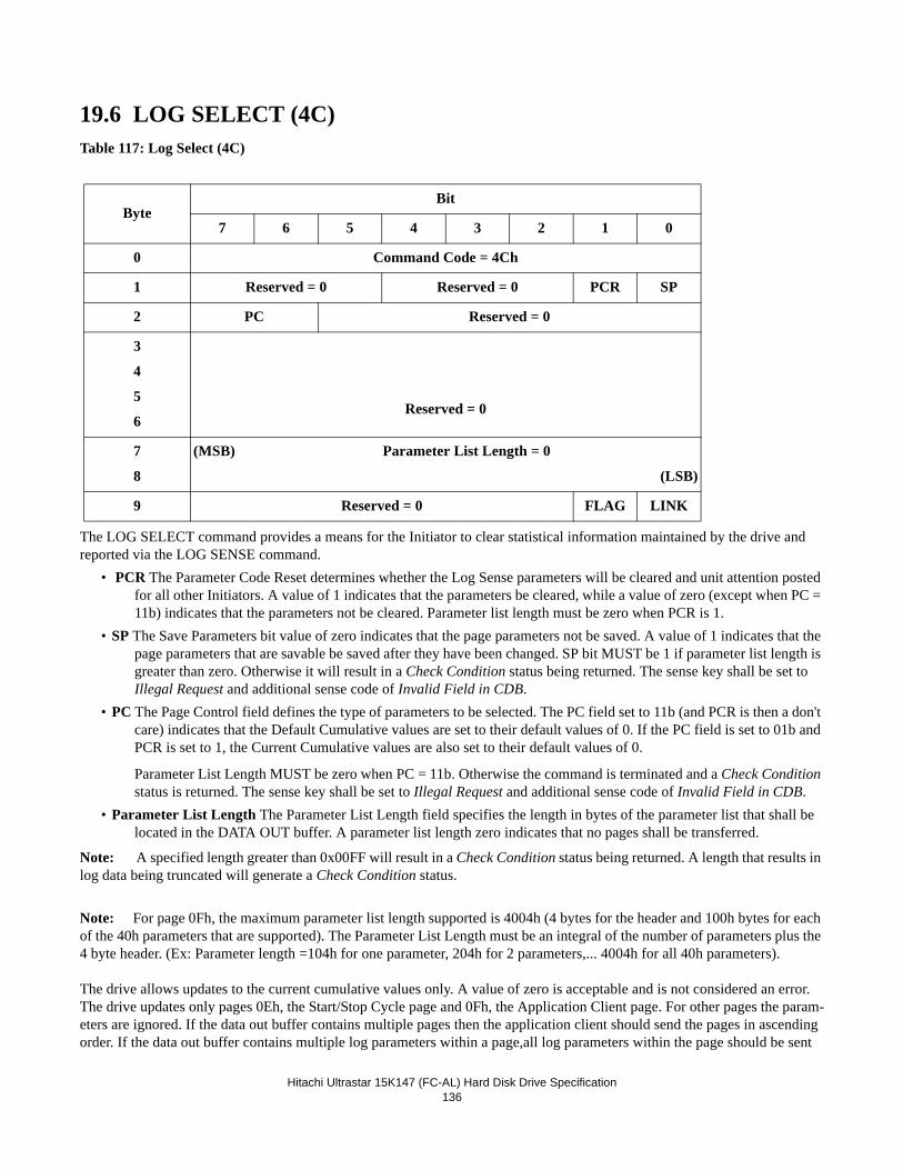
Hitachi Ultrastar 15K147 (FC-AL) Hard Disk Drive Specification
136
19.6 LOG SELECT (4C)Table 117: Log Select (4C)
The LOG SELECT command provides a means for the Initiator to clear statistical information maintained by the drive and reported via the LOG SENSE command.
• PCR The Parameter Code Reset determines whether the Log Sense parameters will be cleared and unit attention posted for all other Initiators. A value of 1 indicates that the parameters be cleared, while a value of zero (except when PC = 11b) indicates that the parameters not be cleared. Parameter list length must be zero when PCR is 1.
• SP The Save Parameters bit value of zero indicates that the page parameters not be saved. A value of 1 indicates that the page parameters that are savable be saved after they have been changed. SP bit MUST be 1 if parameter list length is greater than zero. Otherwise it will result in a Check Condition status being returned. The sense key shall be set to Illegal Request and additional sense code of Invalid Field in CDB.
• PC The Page Control field defines the type of parameters to be selected. The PC field set to 11b (and PCR is then a don't care) indicates that the Default Cumulative values are set to their default values of 0. If the PC field is set to 01b and PCR is set to 1, the Current Cumulative values are also set to their default values of 0.
Parameter List Length MUST be zero when PC = 11b. Otherwise the command is terminated and a Check Condition status is returned. The sense key shall be set to Illegal Request and additional sense code of Invalid Field in CDB.
• Parameter List Length The Parameter List Length field specifies the length in bytes of the parameter list that shall be located in the DATA OUT buffer. A parameter list length zero indicates that no pages shall be transferred.
Note: A specified length greater than 0x00FF will result in a Check Condition status being returned. A length that results in log data being truncated will generate a Check Condition status.
Note: For page 0Fh, the maximum parameter list length supported is 4004h (4 bytes for the header and 100h bytes for each of the 40h parameters that are supported). The Parameter List Length must be an integral of the number of parameters plus the 4 byte header. (Ex: Parameter length =104h for one parameter, 204h for 2 parameters,... 4004h for all 40h parameters).
The drive allows updates to the current cumulative values only. A value of zero is acceptable and is not considered an error.The drive updates only pages 0Eh, the Start/Stop Cycle page and 0Fh, the Application Client page. For other pages the param-eters are ignored. If the data out buffer contains multiple pages then the application client should send the pages in ascending order. If the data out buffer contains multiple log parameters within a page,all log parameters within the page should be sent
ByteBit
7 6 5 4 3 2 1 0
0 Command Code = 4Ch
1 Reserved = 0 Reserved = 0 PCR SP
2 PC Reserved = 0
3
4
5
6Reserved = 0
7
8
(MSB) Parameter List Length = 0
(LSB)
9 Reserved = 0 FLAG LINK
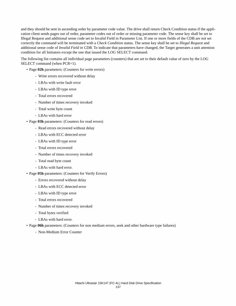
Hitachi Ultrastar 15K147 (FC-AL) Hard Disk Drive Specification
137
and they should be sent in ascending order by parameter code value. The drive shall return Check Condition status if the appli-cation client sends pages out of order, parameter codes out of order or missing parameter code. The sense key shall be set to Illegal Request and additional sense code set to Invalid Field in Parameter List. If one or more fields of the CDB are not set correctly the command will be terminated with a Check Condition status. The sense key shall be set to Illegal Request and additional sense code of Invalid Field in CDB. To indicate that parameters have changed, the Target generates a unit attention condition for all Initiators except the one that issued the LOG SELECT command.
The following list contains all individual page parameters (counters) that are set to their default value of zero by the LOG SELECT command (when PCR=1).
• Page 02h parameters: (Counters for write errors)
- Write errors recovered without delay
- LBAs with write fault error
- LBAs with ID type error
- Total errors recovered
- Number of times recovery invoked
- Total write byte count
- LBAs with hard error• Page 03h parameters: (Counters for read errors)
- Read errors recovered without delay
- LBAs with ECC detected error
- LBAs with ID type error
- Total errors recovered
- Number of times recovery invoked
- Total read byte count
- LBAs with hard error.• Page 05h parameters: (Counters for Verify Errors)
- Errors recovered without delay
- LBAs with ECC detected error
- LBAs with ID type error
- Total errors recovered
- Number of times recovery invoked
- Total bytes verified
- LBAs with hard error.• Page 06h parameters: (Counters for non medium errors, seek and other hardware type failures)
- Non-Medium Error Counter
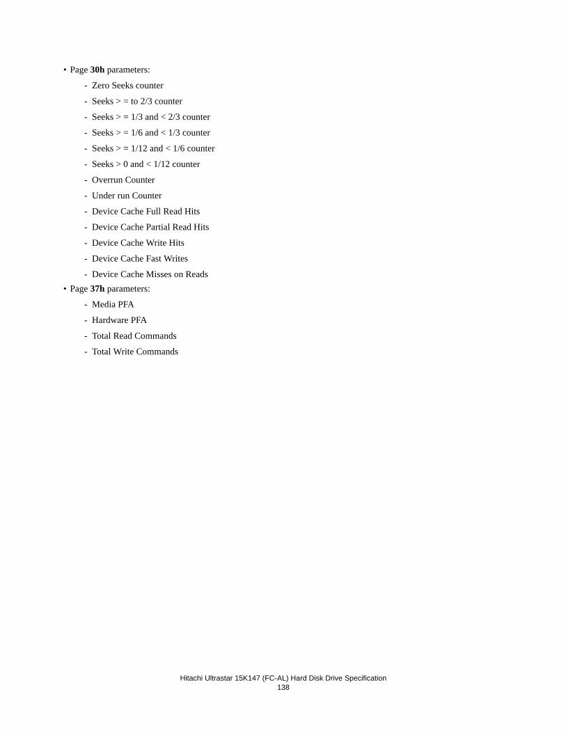
Hitachi Ultrastar 15K147 (FC-AL) Hard Disk Drive Specification
138
• Page 30h parameters:
- Zero Seeks counter
- Seeks > = to 2/3 counter
- Seeks > = 1/3 and < 2/3 counter
- Seeks > = 1/6 and < 1/3 counter
- Seeks > = 1/12 and < 1/6 counter
- Seeks > 0 and < 1/12 counter
- Overrun Counter
- Under run Counter
- Device Cache Full Read Hits
- Device Cache Partial Read Hits
- Device Cache Write Hits
- Device Cache Fast Writes
- Device Cache Misses on Reads• Page 37h parameters:
- Media PFA
- Hardware PFA
- Total Read Commands
- Total Write Commands
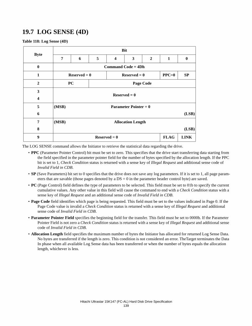
Hitachi Ultrastar 15K147 (FC-AL) Hard Disk Drive Specification
139
19.7 LOG SENSE (4D)Table 118: Log Sense (4D)
The LOG SENSE command allows the Initiator to retrieve the statistical data regarding the drive.• PPC (Parameter Pointer Control) bit must be set to zero. This specifies that the drive start transferring data starting from
the field specified in the parameter pointer field for the number of bytes specified by the allocation length. If the PPC bit is set to 1, Check Condition status is returned with a sense key of Illegal Request and additional sense code of Invalid Field in CDB.
• SP (Save Parameters) bit set to 0 specifies that the drive does not save any log parameters. If it is set to 1, all page param-eters that are savable (those pages denoted by a DS = 0 in the parameter header control byte) are saved.
• PC (Page Control) field defines the type of parameters to be selected. This field must be set to 01b to specify the current cumulative values. Any other value in this field will cause the command to end with a Check Condition status with a sense key of Illegal Request and an additional sense code of Invalid Field in CDB.
• Page Code field identifies which page is being requested. This field must be set to the values indicated in Page 0. If the Page Code value is invalid a Check Condition status is returned with a sense key of Illegal Request and additional sense code of Invalid Field in CDB.
• Parameter Pointer Field specifies the beginning field for the transfer. This field must be set to 0000h. If the Parameter Pointer Field is not zero a Check Condition status is returned with a sense key of Illegal Request and additional sense code of Invalid Field in CDB.
• Allocation Length field specifies the maximum number of bytes the Initiator has allocated for returned Log Sense Data. No bytes are transferred if the length is zero. This condition is not considered an error. TheTarget terminates the Data In phase when all available Log Sense data has been transferred or when the number of bytes equals the allocation length, whichever is less.
ByteBit
7 6 5 4 3 2 1 0
0 Command Code = 4Dh
1 Reserved = 0 Reserved = 0 PPC=0 SP
2 PC Page Code
3
4Reserved = 0
5
6
(MSB) Parameter Pointer = 0
(LSB)
7
8
(MSB) Allocation Length
(LSB)
9 Reserved = 0 FLAG LINK
Hitachi Ultrastar 15K147 (FC-AL) Hard Disk Drive Specification
140
19.7.1 Log Page parametersEach log page begins with a 4-byte page header followed by zero or more variable-length log parameters.
Page header Page Code field identifies which log page is being transferred.The Page Length field specifies the length in bytes of the following log parameters.
Log parameters Each log parameter begins with a 4-byte parameter header followed by one or more bytes of parameter value data.The Parameter Code field identifies which log parameter is being transferred for that log page.The Parameter Control field, the 3rd byte of each parameter header, contains several fields.
- DU The Disable Update bit is set to 0 to indicate that the drive updates the log parameter value to reflect events that should be noted by that parameter.
- DS The Disable Save bit is set to 1 to indicate the parameter is non-savable and is set to 0 to indicate that the parameter is savable.
- TSD The Target Save Disable bit is set to zero to indicate that the drive provides a Target defined method for sav-ing log parameters.
- ETC The enable Threshold Comparison bit is set to 0 to indicate the drive does not perform comparisons between cumulative and any threshold values.
- TMC The Threshold Met Criteria field is not valid because this drive does not perform threshold comparisons. This field is set to 0.
- LBIN The List Binary bit is only valid if the LP is 1. If the LP bit is 1 and the LBIN bit is 0, then the list parameter is a string of ASCII graphic code (20h - 7Eh). If the LP bit is 1 and the LBIN bit is 1, then the list parameter is a list of binary information.
- LP The List Parameter bit is set to 0 for parameters that are data counters. The LP bit is set to 1 for parameters that are lists.
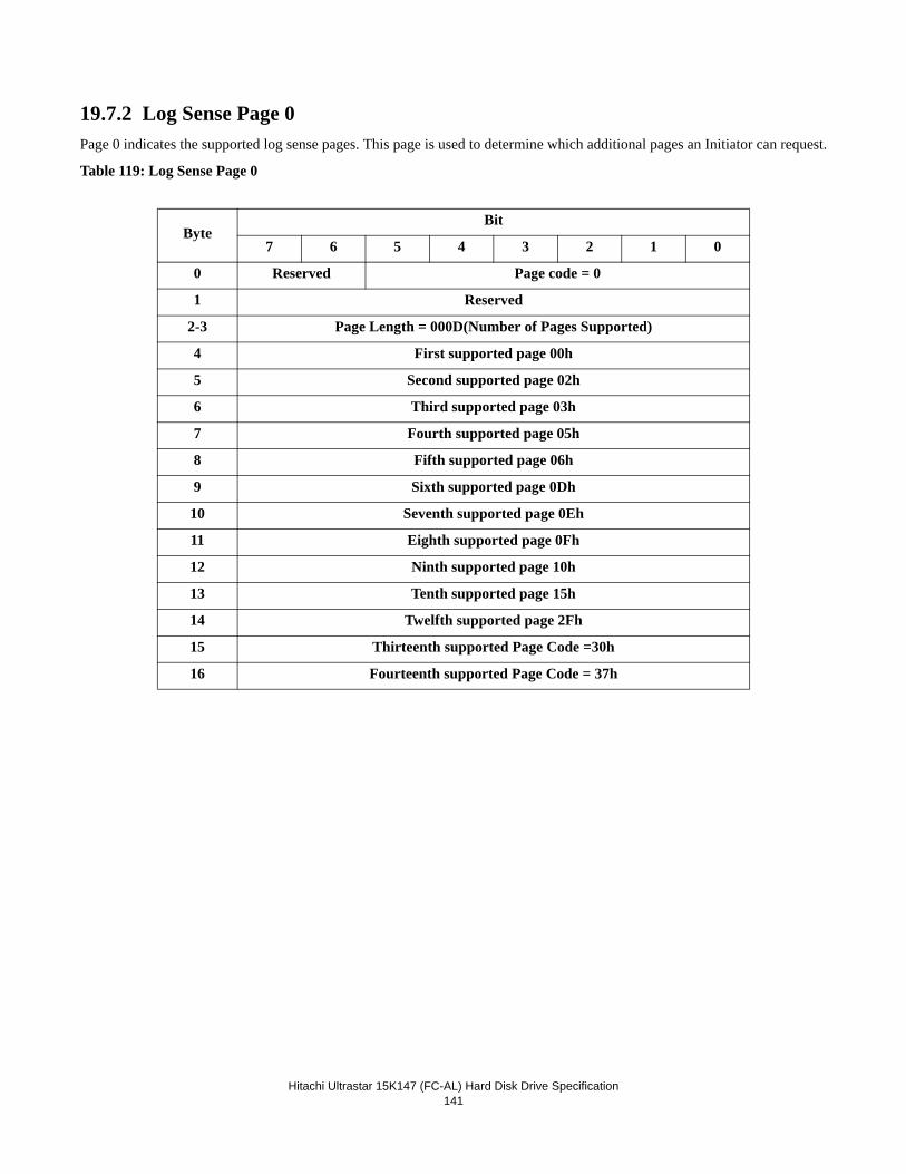
Hitachi Ultrastar 15K147 (FC-AL) Hard Disk Drive Specification
141
19.7.2 Log Sense Page 0Page 0 indicates the supported log sense pages. This page is used to determine which additional pages an Initiator can request.
Table 119: Log Sense Page 0
ByteBit
7 6 5 4 3 2 1 0
0 Reserved Page code = 0
1 Reserved
2-3 Page Length = 000D(Number of Pages Supported)
4 First supported page 00h
5 Second supported page 02h
6 Third supported page 03h
7 Fourth supported page 05h
8 Fifth supported page 06h
9 Sixth supported page 0Dh
10 Seventh supported page 0Eh
11 Eighth supported page 0Fh
12 Ninth supported page 10h
13 Tenth supported page 15h
14 Twelfth supported page 2Fh
15 Thirteenth supported Page Code =30h
16 Fourteenth supported Page Code = 37h
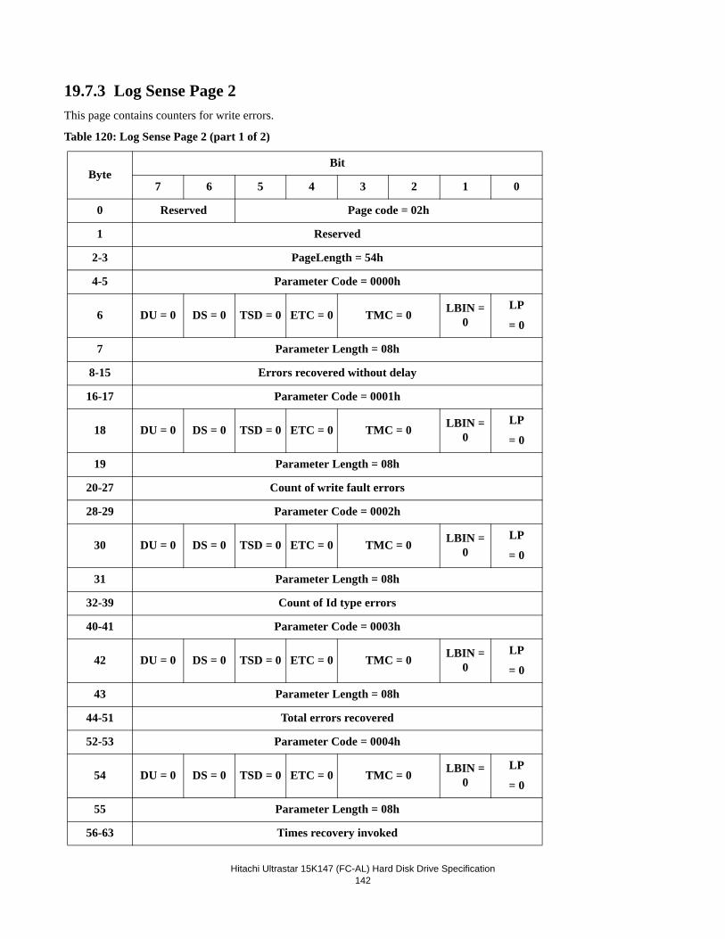
Hitachi Ultrastar 15K147 (FC-AL) Hard Disk Drive Specification
142
19.7.3 Log Sense Page 2This page contains counters for write errors.
Table 120: Log Sense Page 2 (part 1 of 2)
ByteBit
7 6 5 4 3 2 1 0
0 Reserved Page code = 02h
1 Reserved
2-3 PageLength = 54h
4-5 Parameter Code = 0000h
6 DU = 0 DS = 0 TSD = 0 ETC = 0 TMC = 0 LBIN = 0
LP
= 0
7 Parameter Length = 08h
8-15 Errors recovered without delay
16-17 Parameter Code = 0001h
18 DU = 0 DS = 0 TSD = 0 ETC = 0 TMC = 0 LBIN = 0
LP
= 0
19 Parameter Length = 08h
20-27 Count of write fault errors
28-29 Parameter Code = 0002h
30 DU = 0 DS = 0 TSD = 0 ETC = 0 TMC = 0 LBIN = 0
LP
= 0
31 Parameter Length = 08h
32-39 Count of Id type errors
40-41 Parameter Code = 0003h
42 DU = 0 DS = 0 TSD = 0 ETC = 0 TMC = 0 LBIN = 0
LP
= 0
43 Parameter Length = 08h
44-51 Total errors recovered
52-53 Parameter Code = 0004h
54 DU = 0 DS = 0 TSD = 0 ETC = 0 TMC = 0 LBIN = 0
LP
= 0
55 Parameter Length = 08h
56-63 Times recovery invoked
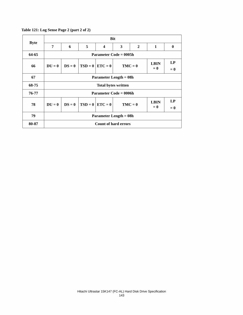
Hitachi Ultrastar 15K147 (FC-AL) Hard Disk Drive Specification
143
Table 121: Log Sense Page 2 (part 2 of 2)
ByteBit
7 6 5 4 3 2 1 0
64-65 Parameter Code = 0005h
66 DU = 0 DS = 0 TSD = 0 ETC = 0 TMC = 0 LBIN = 0
LP
= 0
67 Parameter Length = 08h
68-75 Total bytes written
76-77 Parameter Code = 0006h
78 DU = 0 DS = 0 TSD = 0 ETC = 0 TMC = 0 LBIN = 0
LP
= 0
79 Parameter Length = 08h
80-87 Count of hard errors
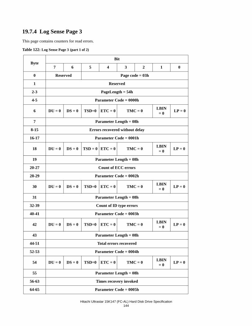
Hitachi Ultrastar 15K147 (FC-AL) Hard Disk Drive Specification
144
19.7.4 Log Sense Page 3This page contains counters for read errors. Table 122: Log Sense Page 3 (part 1 of 2)
ByteBit
7 6 5 4 3 2 1 0
0 Reserved Page code = 03h
1 Reserved
2-3 PageLength = 54h
4-5 Parameter Code = 0000h
6 DU = 0 DS = 0 TSD=0 ETC = 0 TMC = 0 LBIN = 0 LP = 0
7 Parameter Length = 08h
8-15 Errors recovered without delay
16-17 Parameter Code = 0001h
18 DU = 0 DS = 0 TSD = 0 ETC = 0 TMC = 0 LBIN = 0 LP = 0
19 Parameter Length = 08h
20-27 Count of ECC errors
28-29 Parameter Code = 0002h
30 DU = 0 DS = 0 TSD=0 ETC = 0 TMC = 0 LBIN = 0 LP = 0
31 Parameter Length = 08h
32-39 Count of ID type errors
40-41 Parameter Code = 0003h
42 DU = 0 DS = 0 TSD=0 ETC = 0 TMC = 0 LBIN = 0 LP = 0
43 Parameter Length = 08h
44-51 Total errors recovered
52-53 Parameter Code = 0004h
54 DU = 0 DS = 0 TSD=0 ETC = 0 TMC = 0 LBIN = 0 LP = 0
55 Parameter Length = 08h
56-63 Times recovery invoked
64-65 Parameter Code = 0005h
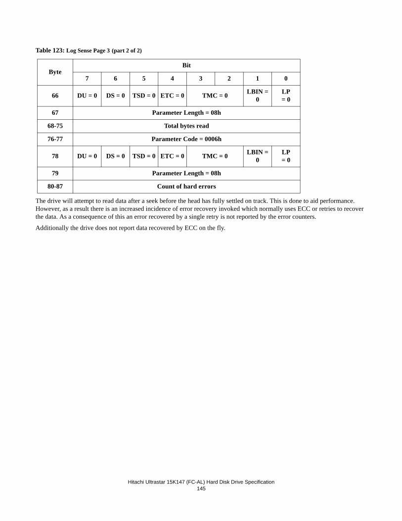
Hitachi Ultrastar 15K147 (FC-AL) Hard Disk Drive Specification
145
Table 123: Log Sense Page 3 (part 2 of 2)
The drive will attempt to read data after a seek before the head has fully settled on track. This is done to aid performance. However, as a result there is an increased incidence of error recovery invoked which normally uses ECC or retries to recover the data. As a consequence of this an error recovered by a single retry is not reported by the error counters.
Additionally the drive does not report data recovered by ECC on the fly.
ByteBit
7 6 5 4 3 2 1 0
66 DU = 0 DS = 0 TSD = 0 ETC = 0 TMC = 0 LBIN = 0
LP= 0
67 Parameter Length = 08h
68-75 Total bytes read
76-77 Parameter Code = 0006h
78 DU = 0 DS = 0 TSD = 0 ETC = 0 TMC = 0 LBIN = 0
LP= 0
79 Parameter Length = 08h
80-87 Count of hard errors
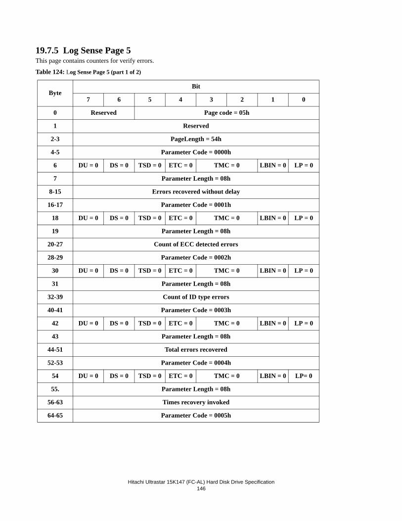
Hitachi Ultrastar 15K147 (FC-AL) Hard Disk Drive Specification
146
19.7.5 Log Sense Page 5This page contains counters for verify errors.
Table 124: Log Sense Page 5 (part 1 of 2)
ByteBit
7 6 5 4 3 2 1 0
0 Reserved Page code = 05h
1 Reserved
2-3 PageLength = 54h
4-5 Parameter Code = 0000h
6 DU = 0 DS = 0 TSD = 0 ETC = 0 TMC = 0 LBIN = 0 LP = 0
7 Parameter Length = 08h
8-15 Errors recovered without delay
16-17 Parameter Code = 0001h
18 DU = 0 DS = 0 TSD = 0 ETC = 0 TMC = 0 LBIN = 0 LP = 0
19 Parameter Length = 08h
20-27 Count of ECC detected errors
28-29 Parameter Code = 0002h
30 DU = 0 DS = 0 TSD = 0 ETC = 0 TMC = 0 LBIN = 0 LP = 0
31 Parameter Length = 08h
32-39 Count of ID type errors
40-41 Parameter Code = 0003h
42 DU = 0 DS = 0 TSD = 0 ETC = 0 TMC = 0 LBIN = 0 LP = 0
43 Parameter Length = 08h
44-51 Total errors recovered
52-53 Parameter Code = 0004h
54 DU = 0 DS = 0 TSD = 0 ETC = 0 TMC = 0 LBIN = 0 LP= 0
55. Parameter Length = 08h
56-63 Times recovery invoked
64-65 Parameter Code = 0005h
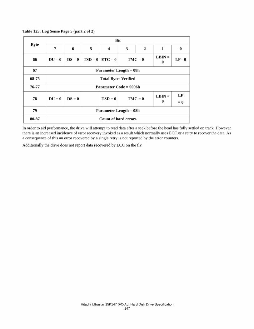
Hitachi Ultrastar 15K147 (FC-AL) Hard Disk Drive Specification
147
Table 125: Log Sense Page 5 (part 2 of 2)
In order to aid performance, the drive will attempt to read data after a seek before the head has fully settled on track. However there is an increased incidence of error recovery invoked as a result which normally uses ECC or a retry to recover the data. As a consequence of this an error recovered by a single retry is not reported by the error counters.
Additionally the drive does not report data recovered by ECC on the fly.
ByteBit
7 6 5 4 3 2 1 0
66 DU = 0 DS = 0 TSD = 0 ETC = 0 TMC = 0 LBIN = 0 LP= 0
67 Parameter Length = 08h
68-75 Total Bytes Verified
76-77 Parameter Code = 0006h
78 DU = 0 DS = 0 TSD = 0 TMC = 0 LBIN = 0
LP
= 0
79 Parameter Length = 08h
80-87 Count of hard errors
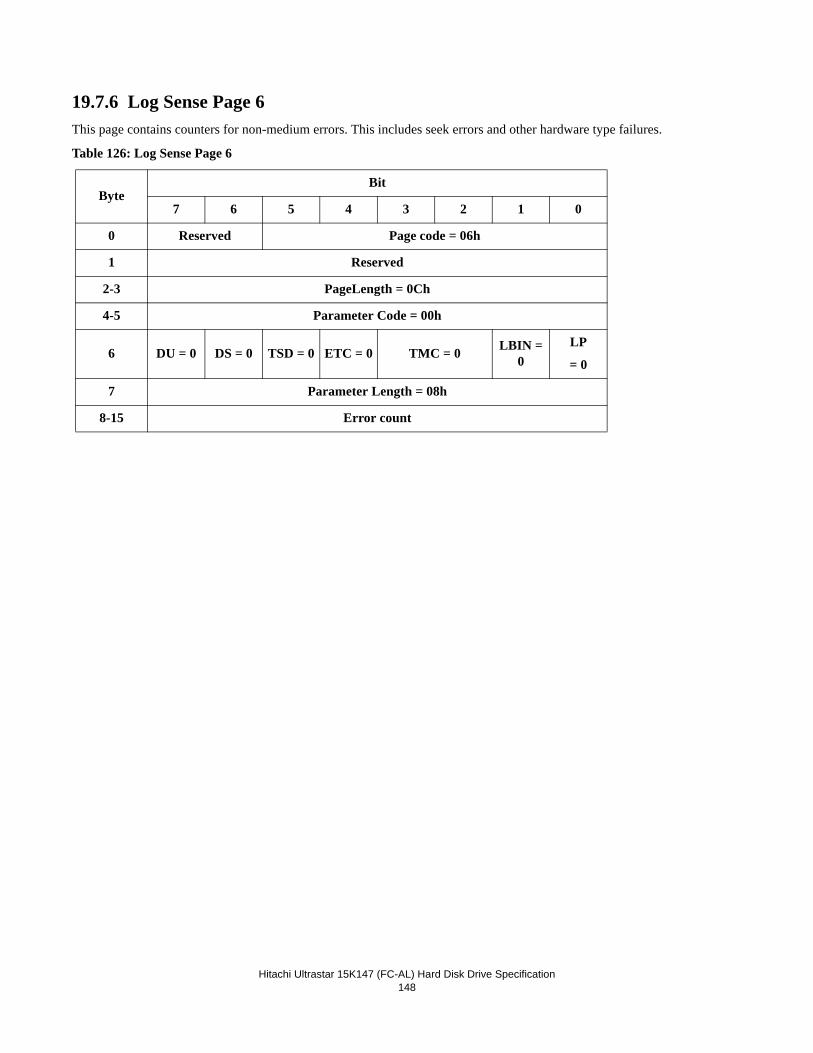
Hitachi Ultrastar 15K147 (FC-AL) Hard Disk Drive Specification
148
19.7.6 Log Sense Page 6This page contains counters for non-medium errors. This includes seek errors and other hardware type failures.
Table 126: Log Sense Page 6
ByteBit
7 6 5 4 3 2 1 0
0 Reserved Page code = 06h
1 Reserved
2-3 PageLength = 0Ch
4-5 Parameter Code = 00h
6 DU = 0 DS = 0 TSD = 0 ETC = 0 TMC = 0 LBIN = 0
LP
= 0
7 Parameter Length = 08h
8-15 Error count
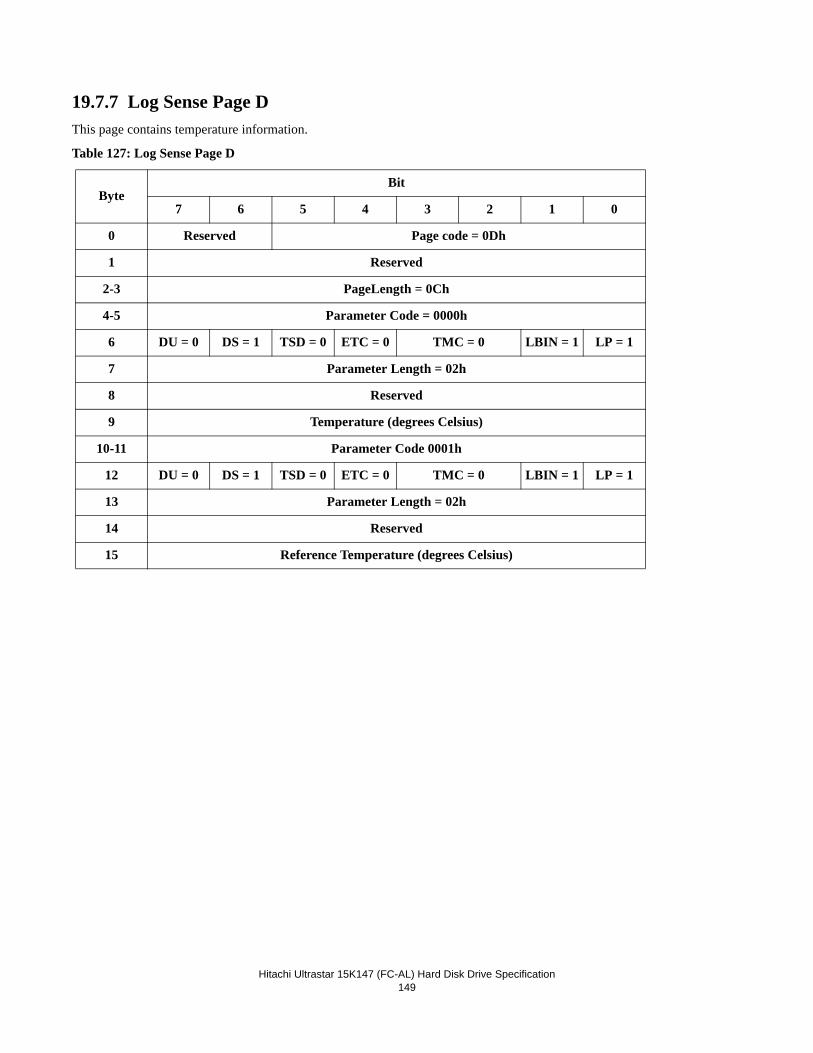
Hitachi Ultrastar 15K147 (FC-AL) Hard Disk Drive Specification
149
19.7.7 Log Sense Page DThis page contains temperature information.
Table 127: Log Sense Page D
ByteBit
7 6 5 4 3 2 1 0
0 Reserved Page code = 0Dh
1 Reserved
2-3 PageLength = 0Ch
4-5 Parameter Code = 0000h
6 DU = 0 DS = 1 TSD = 0 ETC = 0 TMC = 0 LBIN = 1 LP = 1
7 Parameter Length = 02h
8 Reserved
9 Temperature (degrees Celsius)
10-11 Parameter Code 0001h
12 DU = 0 DS = 1 TSD = 0 ETC = 0 TMC = 0 LBIN = 1 LP = 1
13 Parameter Length = 02h
14 Reserved
15 Reference Temperature (degrees Celsius)
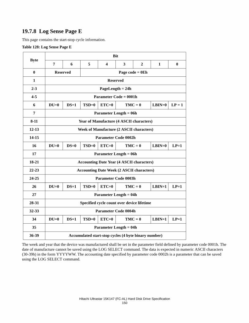
Hitachi Ultrastar 15K147 (FC-AL) Hard Disk Drive Specification
150
19.7.8 Log Sense Page EThis page contains the start-stop cycle information.
Table 128: Log Sense Page E
The week and year that the device was manufactured shall be set in the parameter field defined by parameter code 0001h. The date of manufacture cannot be saved using the LOG SELECT command. The data is expected in numeric ASCII characters (30-39h) in the form YYYYWW. The accounting date specified by parameter code 0002h is a parameter that can be saved using the LOG SELECT command.
ByteBit
7 6 5 4 3 2 1 0
0 Reserved Page code = 0Eh
1 Reserved
2-3 PageLength = 24h
4-5 Parameter Code = 0001h
6 DU=0 DS=1 TSD=0 ETC=0 TMC = 0 LBIN=0 LP = 1
7 Parameter Length = 06h
8-11 Year of Manufacture (4 ASCII characters)
12-13 Week of Manufacture (2 ASCII characters)
14-15 Parameter Code 0002h
16 DU=0 DS=0 TSD=0 ETC=0 TMC = 0 LBIN=0 LP=1
17 Parameter Length = 06h
18-21 Accounting Date Year (4 ASCII characters)
22-23 Accounting Date Week (2 ASCII characters)
24-25 Parameter Code 0003h
26 DU=0 DS=1 TSD=0 ETC=0 TMC = 0 LBIN=1 LP=1
27 Parameter Length = 04h
28-31 Specified cycle count over device lifetime
32-33 Parameter Code 0004h
34 DU=0 DS=1 TSD=0 ETC=0 TMC = 0 LBIN=1 LP=1
35 Parameter Length = 04h
36-39 Accumulated start-stop cycles (4 byte binary number)
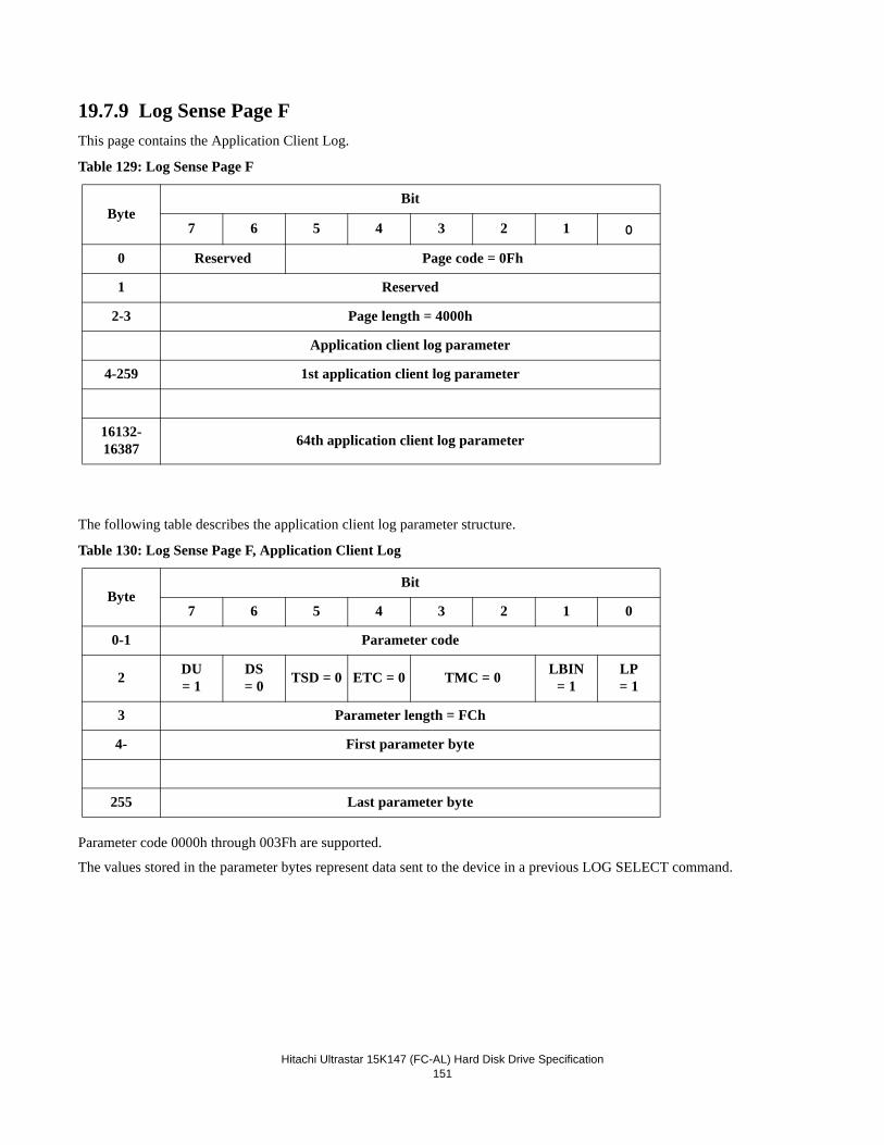
Hitachi Ultrastar 15K147 (FC-AL) Hard Disk Drive Specification
151
19.7.9 Log Sense Page FThis page contains the Application Client Log.
Table 129: Log Sense Page F
The following table describes the application client log parameter structure.
Table 130: Log Sense Page F, Application Client Log
Parameter code 0000h through 003Fh are supported.
The values stored in the parameter bytes represent data sent to the device in a previous LOG SELECT command.
ByteBit
7 6 5 4 3 2 1 0
0 Reserved Page code = 0Fh
1 Reserved
2-3 Page length = 4000h
Application client log parameter
4-259 1st application client log parameter
16132-16387 64th application client log parameter
ByteBit
7 6 5 4 3 2 1 0
0-1 Parameter code
2 DU= 1
DS= 0 TSD = 0 ETC = 0 TMC = 0 LBIN
= 1LP= 1
3 Parameter length = FCh
4- First parameter byte
255 Last parameter byte
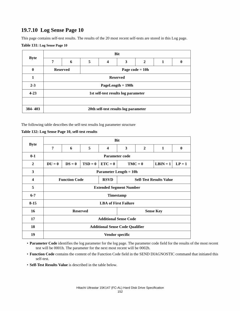
Hitachi Ultrastar 15K147 (FC-AL) Hard Disk Drive Specification
152
19.7.10 Log Sense Page 10This page contains self-test results. The results of the 20 most recent self-tests are stored in this Log page.
Table 131: Log Sense Page 10
The following table describes the self-test results log parameter structure
Table 132: Log Sense Page 10, self-test results
• Parameter Code identifies the log parameter for the log page. The parameter code field for the results of the most recent test will be 0001h. The parameter for the next most recent will be 0002h.
• Function Code contains the content of the Function Code field in the SEND DIAGNOSTIC command that initiated this self-test.
• Self-Test Results Value is described in the table below.
ByteBit
7 6 5 4 3 2 1 0
0 Reserved Page code = 10h
1 Reserved
2-3 PageLength = 190h
4-23 1st self-test results log parameter
384- 403 20th self-test results log parameter
ByteBit
7 6 5 4 3 2 1 0
0-1 Parameter code
2 DU = 0 DS = 0 TSD = 0 ETC = 0 TMC = 0 LBIN = 1 LP = 1
3 Parameter Length = 10h
4 Function Code RSVD Self-Test Results Value
5 Extended Segment Number
6-7 Timestamp
8-15 LBA of First Failure
16 Reserved Sense Key
17 Additional Sense Code
18 Additional Sense Code Qualifier
19 Vendor specific
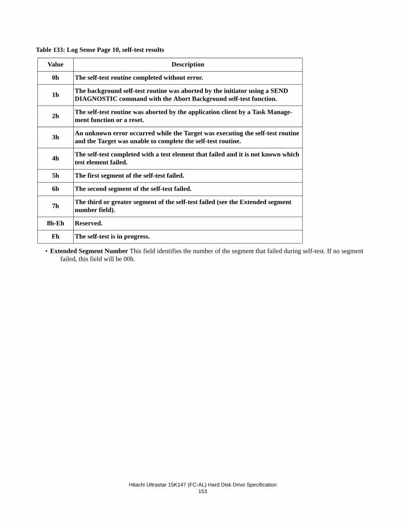
Hitachi Ultrastar 15K147 (FC-AL) Hard Disk Drive Specification
153
Table 133: Log Sense Page 10, self-test results
• Extended Segment Number This field identifies the number of the segment that failed during self-test. If no segment failed, this field will be 00h.
Value Description
0h The self-test routine completed without error.
1h The background self-test routine was aborted by the initiator using a SEND DIAGNOSTIC command with the Abort Background self-test function.
2h The self-test routine was aborted by the application client by a Task Manage-ment function or a reset.
3h An unknown error occurred while the Target was executing the self-test routine and the Target was unable to complete the self-test routine.
4h The self-test completed with a test element that failed and it is not known which test element failed.
5h The first segment of the self-test failed.
6h The second segment of the self-test failed.
7h The third or greater segment of the self-test failed (see the Extended segment number field).
8h-Eh Reserved.
Fh The self-test is in progress.
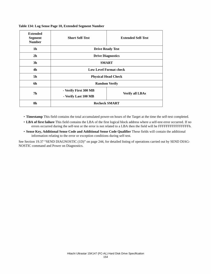
Hitachi Ultrastar 15K147 (FC-AL) Hard Disk Drive Specification
154
Table 134: Log Sense Page 10, Extended Segment Number
• Timestamp This field contains the total accumulated power-on hours of the Target at the time the self-test completed.• LBA of first failure This field contains the LBA of the first logical block address where a self-test error occurred. If no
errors occurred during the self-test or the error is not related to a LBA then the field will be FFFFFFFFFFFFFFFFh.• Sense Key, Additional Sense Code and Additional Sense Code Qualifier These fields will contain the additional
information relating to the error or exception conditions during self-test.
See Section 19.37 “SEND DIAGNOSTIC (1D)” on page 244, for detailed listing of operations carried out by SEND DIAG-NOSTIC command and Power on Diagnostics.
ExtendedSegmentNumber
Short Self-Test Extended Self-Test
1h Drive Ready Test
2h Drive Diagnostics
3h SMART
4h Low Level Format check
5h Physical Head Check
6h Random Verify
7h- Verify First 300 MB
- Verify Last 100 MBVerify all LBAs
8h Recheck SMART
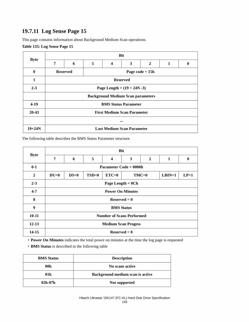
Hitachi Ultrastar 15K147 (FC-AL) Hard Disk Drive Specification
155
19.7.11 Log Sense Page 15This page contains information about Background Medium Scan operations.
Table 135: Log Sense Page 15
The following table describes the BMS Status Parameter structure.
• Power On Minutes indicates the total power on minutes at the time the log page is requested• BMS Status is described in the following table
ByteBit
7 6 5 4 3 2 1 0
0 Reserved Page code = 15h
1 Reserved
2-3 Page Length = (19 + 24N -3)
Background Medium Scan parameters
4-19 BMS Status Parameter
20-43 First Medium Scan Parameter
...
19+24N Last Medium Scan Parameter
ByteBit
7 6 5 4 3 2 1 0
0-1 Parameter Code = 0000h
2 DU=0 DS=0 TSD=0 ETC=0 TMC=0 LBIN=1 LP=1
2-3 Page Length = 0Ch
4-7 Power On Minutes
8 Reserved = 0
9 BMS Status
10-11 Number of Scans Performed
12-13 Medium Scan Progess
14-15 Reserved = 0
BMS Status Description
00h No scans active
01h Background medium scan is active
02h-07h Not supported
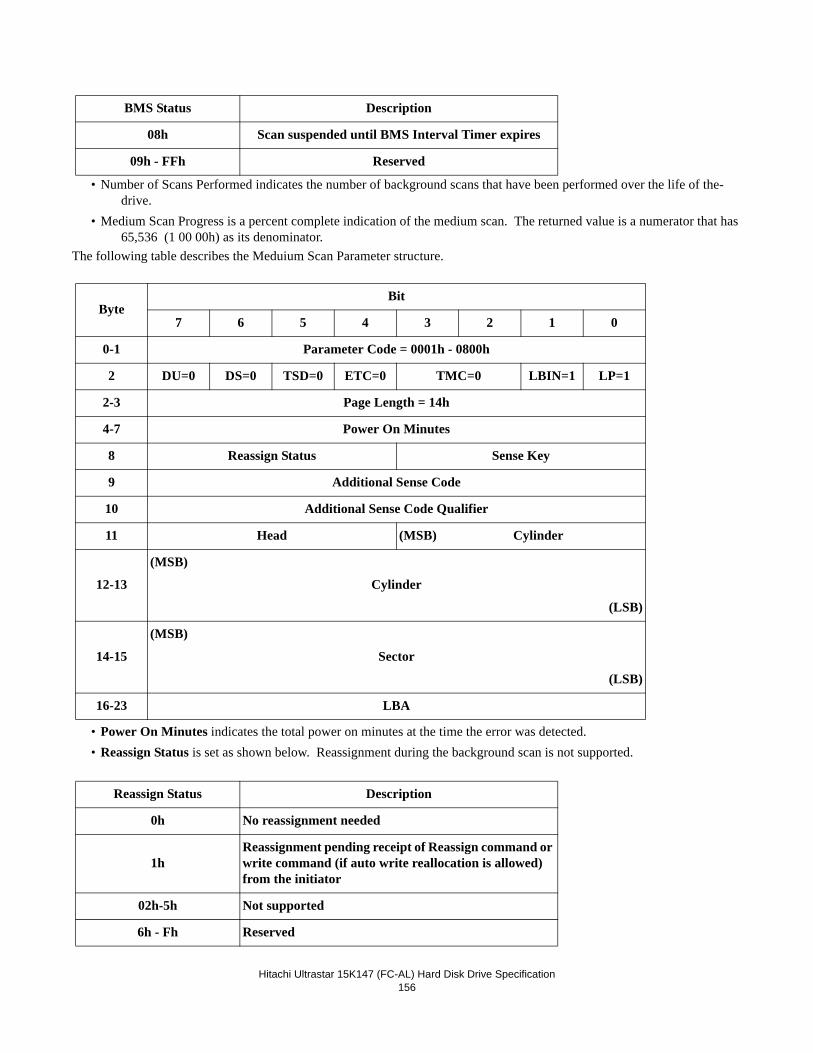
Hitachi Ultrastar 15K147 (FC-AL) Hard Disk Drive Specification
156
• Number of Scans Performed indicates the number of background scans that have been performed over the life of the-drive.
• Medium Scan Progress is a percent complete indication of the medium scan. The returned value is a numerator that has 65,536 (1 00 00h) as its denominator.
The following table describes the Meduium Scan Parameter structure.
• Power On Minutes indicates the total power on minutes at the time the error was detected.• Reassign Status is set as shown below. Reassignment during the background scan is not supported.
08h Scan suspended until BMS Interval Timer expires
09h - FFh Reserved
ByteBit
7 6 5 4 3 2 1 0
0-1 Parameter Code = 0001h - 0800h
2 DU=0 DS=0 TSD=0 ETC=0 TMC=0 LBIN=1 LP=1
2-3 Page Length = 14h
4-7 Power On Minutes
8 Reassign Status Sense Key
9 Additional Sense Code
10 Additional Sense Code Qualifier
11 Head (MSB) Cylinder
12-13
(MSB)
Cylinder
(LSB)
14-15
(MSB)
Sector
(LSB)
16-23 LBA
Reassign Status Description
0h No reassignment needed
1hReassignment pending receipt of Reassign command or write command (if auto write reallocation is allowed) from the initiator
02h-5h Not supported
6h - Fh Reserved
BMS Status Description
Hitachi Ultrastar 15K147 (FC-AL) Hard Disk Drive Specification
157
Additional Sense Code and Additional Sense Code Qualifier provide details about the error detected.
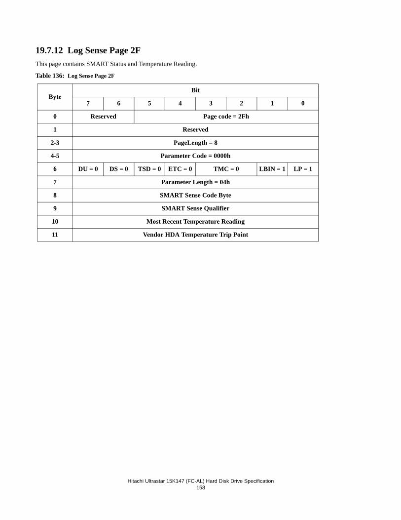
Hitachi Ultrastar 15K147 (FC-AL) Hard Disk Drive Specification
158
19.7.12 Log Sense Page 2FThis page contains SMART Status and Temperature Reading.
Table 136: Log Sense Page 2F
ByteBit
7 6 5 4 3 2 1 0
0 Reserved Page code = 2Fh
1 Reserved
2-3 PageLength = 8
4-5 Parameter Code = 0000h
6 DU = 0 DS = 0 TSD = 0 ETC = 0 TMC = 0 LBIN = 1 LP = 1
7 Parameter Length = 04h
8 SMART Sense Code Byte
9 SMART Sense Qualifier
10 Most Recent Temperature Reading
11 Vendor HDA Temperature Trip Point
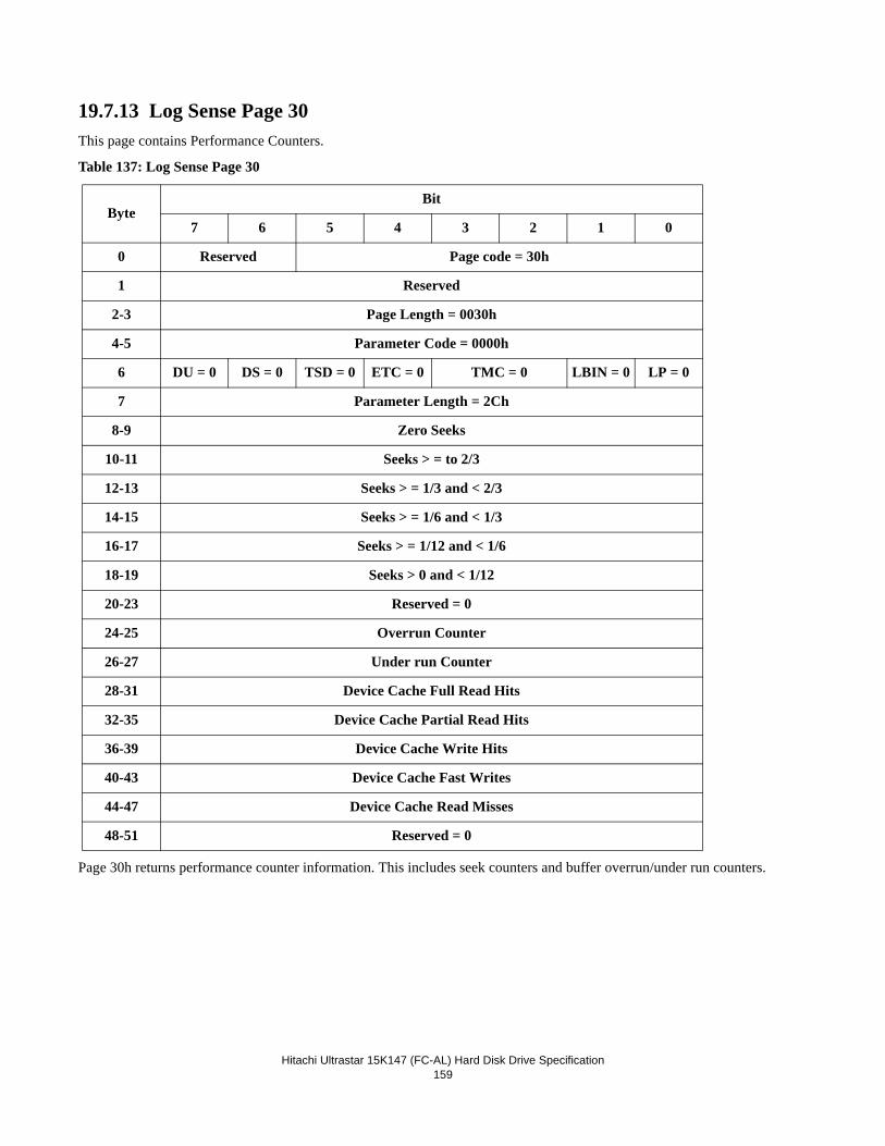
Hitachi Ultrastar 15K147 (FC-AL) Hard Disk Drive Specification
159
19.7.13 Log Sense Page 30This page contains Performance Counters.
Table 137: Log Sense Page 30
Page 30h returns performance counter information. This includes seek counters and buffer overrun/under run counters.
ByteBit
7 6 5 4 3 2 1 0
0 Reserved Page code = 30h
1 Reserved
2-3 Page Length = 0030h
4-5 Parameter Code = 0000h
6 DU = 0 DS = 0 TSD = 0 ETC = 0 TMC = 0 LBIN = 0 LP = 0
7 Parameter Length = 2Ch
8-9 Zero Seeks
10-11 Seeks > = to 2/3
12-13 Seeks > = 1/3 and < 2/3
14-15 Seeks > = 1/6 and < 1/3
16-17 Seeks > = 1/12 and < 1/6
18-19 Seeks > 0 and < 1/12
20-23 Reserved = 0
24-25 Overrun Counter
26-27 Under run Counter
28-31 Device Cache Full Read Hits
32-35 Device Cache Partial Read Hits
36-39 Device Cache Write Hits
40-43 Device Cache Fast Writes
44-47 Device Cache Read Misses
48-51 Reserved = 0
Hitachi Ultrastar 15K147 (FC-AL) Hard Disk Drive Specification
160
The appropriate seek counter is incremented once during execution of each of the following SCSI commands: • PRE-FETCH• READ (6)• READ (10)• VERIFY• VERIFY (16)• WRITE (6)• WRITE (10)• WRITE AND VERIFY• WRITE AND VERIFY (16)• WRITE SAME• WRITE SAME (16)• SEEK (6)• SEEK (10)
Only one seek counter is incremented for each of these commands and the counter is incremented only once per command. The length of the initial seek that is required to access the first Logical Block specified for the SCSI command determines which seek counter is incremented. The Zero Seek counter is incremented if a seek is not required or if only a head switch is required to access the first Logical Block. After the initial seek, no further counter incrementing is performed for that com-mand.
Note: The length of a seek as reported in page 30 may differ from expected results. The reason for this is that the drive exe-cutes Idle Time Functions between operations of the drive. The seek operations that occur in Idle Time Functions are not directly entered into page 30 seek counters but they change the length of the following seek. This is because after the Idle Time Function is completed, the heads will not necessarily be in the same position as they were at the completion of the previous command.
A buffer overrun or under run condition occurs when the Initiator does not transfer data to or from the Target data buffer fast enough to keep up with reading or writing the media. The buffer overrun counter is incremented during operations that require a Data In phase when a buffer full condition prevents the continued transfer of data from the media to the data buffer. The buffer under run counter is incremented during operations that require a Data Out phase when a buffer empty condition pre-vents the start or continuation of a data transfer from the data buffer to the media (or a data transfer from the media for a Verify command with BytChk=1).
Buffer Overrun conditions are detected during the following SCSI commands:• READ (6)• READ (10)
Buffer Under Run conditions are detected during the following SCSI commands:• VERIFY WITH BytChk=1• VERIFY (16) WITH BytChk=1• WRITE (6)• WRITE (10)• WRITE AND VERIFY• WRITE AND VERIFY (16)• WRITE SAME• WRITE SAME (16)• ZERO SEEKS
The number of times no seek was required. The operation may have resulted in a head switch.
Hitachi Ultrastar 15K147 (FC-AL) Hard Disk Drive Specification
161
• SEEKS >= 2/3 DISK The number of seeks equal to or greater than 2/3 of the disk.
• SEEKS >= 1/3 AND < 2/3 DISK The number of seeks equal to or greater than 1/3 and less than 2/3 of the disk.
• SEEKS >= 1/6 AND < 1/3 DISK The number of seeks equal to or greater than 1/6 and less than 1/3 of the disk.
• SEEKS >= 1/12 AND < 1/6 DISK The number of seeks equal to or greater than 1/12 and less than 1/6 of the disk.
• SEEKS > 0 AND < 1/12 DISK The number of seeks less than 1/12 of the disk.
• OVERRUN COUNTERThe number of times that data was available to be transferred from the media but the device buffer still contained data that had not been retrieved by the Initiator. Consequently, the disk had to take additional revolutions until the buffer was available to accept data.
• UNDER RUN COUNTERThe number of times that the drive was ready to transfer data to its disk (on a write), but its buffer was empty (i.e., had not been filled by the Initiator), thus the disk was forced to take extra revolutions.
• DEVICE CACHE FULL READ HITSThe number of times that all of the data requested by the read operation was obtained from the device read or write cache.
• DEVICE CACHE PARTIAL READ HITSThe number of times that a portion, but not all, of the data requested by the read operation was obtained from the device read or write cache. A physical operation to the device media was required to obtain the remaining data.
• DEVICE CACHE WRITE HITSThe number of times that the data associated with a write operation replaces, or is combined with, existing data in the device write cache, thereby eliminating a write operation.
• DEVICE CACHE FAST WRITESThe number of times that space was available in the device write cache for the data associated with a write operation and a response was returned immediately.
• DEVICE CACHE READ MISSES
The number of times that none of the data requested by the read operation was obtained from the read cache.
The statistics reported by this page are lost on a self-initiated reset or when the Drive is powered off. Even though the DS field equals zero, the parameters on this page are not savable.
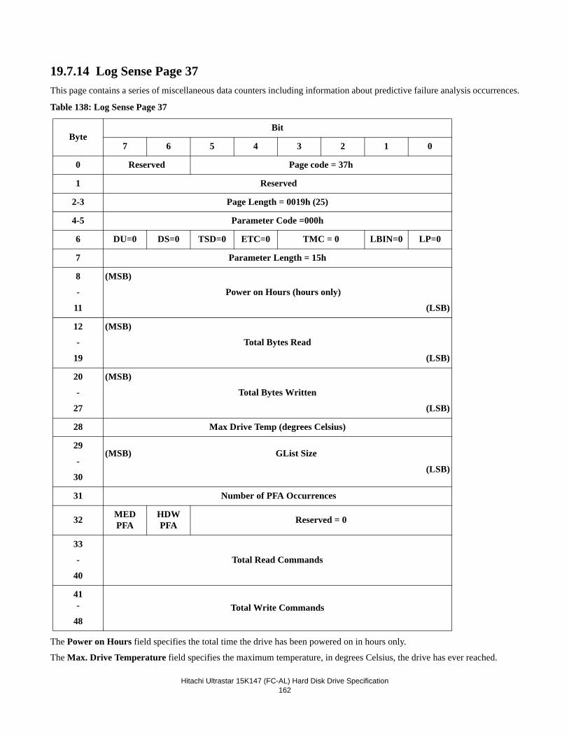
Hitachi Ultrastar 15K147 (FC-AL) Hard Disk Drive Specification
162
19.7.14 Log Sense Page 37This page contains a series of miscellaneous data counters including information about predictive failure analysis occurrences.
Table 138: Log Sense Page 37
The Power on Hours field specifies the total time the drive has been powered on in hours only.
The Max. Drive Temperature field specifies the maximum temperature, in degrees Celsius, the drive has ever reached.
ByteBit
7 6 5 4 3 2 1 0
0 Reserved Page code = 37h
1 Reserved
2-3 Page Length = 0019h (25)
4-5 Parameter Code =000h
6 DU=0 DS=0 TSD=0 ETC=0 TMC = 0 LBIN=0 LP=0
7 Parameter Length = 15h
8
-
11
(MSB)
Power on Hours (hours only)
(LSB)
12
-
19
(MSB)
Total Bytes Read
(LSB)
20
-
27
(MSB)
Total Bytes Written
(LSB)
28 Max Drive Temp (degrees Celsius)
29
-
30
(MSB) GList Size
(LSB)
31 Number of PFA Occurrences
32 MED PFA
HDW PFA Reserved = 0
33
-
40
Total Read Commands
41-
48Total Write Commands
Hitachi Ultrastar 15K147 (FC-AL) Hard Disk Drive Specification
163
The Glist Size field gives the total number of LBAs that have been reassigned on the drive.
The Number of PFA Occurrences field gives the number of PFA occurrences during the life of the drive and not the number of PFA events that have been reported. The number of reported PFA events may be less due to the settings of Mode Page 0x1C.
If set, the Media and Hardware PFA bits indicate that a PFA trip has occurred during the life of the drive. These flags are set during a PFA occurrence that may or may not coincide with the reporting of a PFA event as mentioned above.
Total Read Commands counter is incremented for each Read (6) and Read (10) command received.
Total Write Commands counter is incremented for each Write (6), Write (10), Write Verify and Write Verify (16) command received.
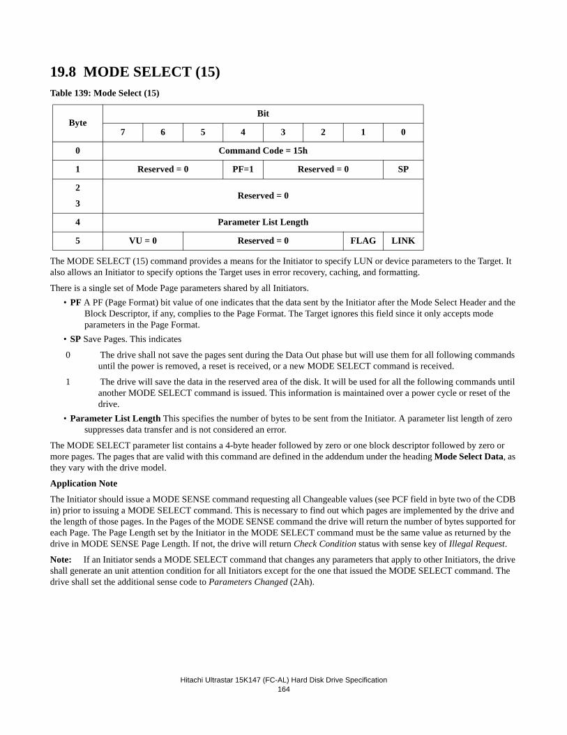
Hitachi Ultrastar 15K147 (FC-AL) Hard Disk Drive Specification
164
19.8 MODE SELECT (15)Table 139: Mode Select (15)
The MODE SELECT (15) command provides a means for the Initiator to specify LUN or device parameters to the Target. It also allows an Initiator to specify options the Target uses in error recovery, caching, and formatting.
There is a single set of Mode Page parameters shared by all Initiators.• PF A PF (Page Format) bit value of one indicates that the data sent by the Initiator after the Mode Select Header and the
Block Descriptor, if any, complies to the Page Format. The Target ignores this field since it only accepts mode parameters in the Page Format.
• SP Save Pages. This indicates
0 The drive shall not save the pages sent during the Data Out phase but will use them for all following commands until the power is removed, a reset is received, or a new MODE SELECT command is received.
1 The drive will save the data in the reserved area of the disk. It will be used for all the following commands until another MODE SELECT command is issued. This information is maintained over a power cycle or reset of the drive.
• Parameter List Length This specifies the number of bytes to be sent from the Initiator. A parameter list length of zero suppresses data transfer and is not considered an error.
The MODE SELECT parameter list contains a 4-byte header followed by zero or one block descriptor followed by zero or more pages. The pages that are valid with this command are defined in the addendum under the heading Mode Select Data, as they vary with the drive model.
Application Note
The Initiator should issue a MODE SENSE command requesting all Changeable values (see PCF field in byte two of the CDB in) prior to issuing a MODE SELECT command. This is necessary to find out which pages are implemented by the drive and the length of those pages. In the Pages of the MODE SENSE command the drive will return the number of bytes supported for each Page. The Page Length set by the Initiator in the MODE SELECT command must be the same value as returned by the drive in MODE SENSE Page Length. If not, the drive will return Check Condition status with sense key of Illegal Request.
Note: If an Initiator sends a MODE SELECT command that changes any parameters that apply to other Initiators, the drive shall generate an unit attention condition for all Initiators except for the one that issued the MODE SELECT command. The drive shall set the additional sense code to Parameters Changed (2Ah).
ByteBit
7 6 5 4 3 2 1 0
0 Command Code = 15h
1 Reserved = 0 PF=1 Reserved = 0 SP
2
3Reserved = 0
4 Parameter List Length
5 VU = 0 Reserved = 0 FLAG LINK
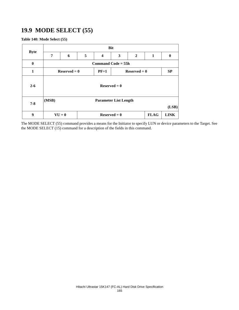
Hitachi Ultrastar 15K147 (FC-AL) Hard Disk Drive Specification
165
19.9 MODE SELECT (55)Table 140: Mode Select (55)
The MODE SELECT (55) command provides a means for the Initiator to specify LUN or device parameters to the Target. See the MODE SELECT (15) command for a description of the fields in this command.
ByteBit
7 6 5 4 3 2 1 0
0 Command Code = 55h
1 Reserved = 0 PF=1 Reserved = 0 SP
2-6 Reserved = 0
7-8(MSB) Parameter List Length
(LSB)
9 VU = 0 Reserved = 0 FLAG LINK
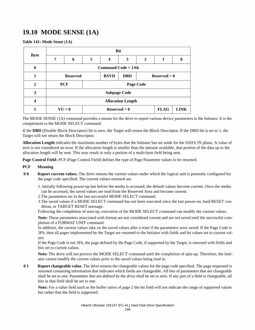
Hitachi Ultrastar 15K147 (FC-AL) Hard Disk Drive Specification
166
19.10 MODE SENSE (1A)Table 141: Mode Sense (1A)
The MODE SENSE (1A) command provides a means for the drive to report various device parameters to the Initiator. It is the complement to the MODE SELECT command.
If the DBD (Disable Block Descriptor) bit is zero, the Target will return the Block Descriptor. If the DBD bit is set to 1, the Target will not return the Block Descriptor.
Allocation Length indicates the maximum number of bytes that the Initiator has set aside for the DATA IN phase. A value of zero is not considered an error. If the allocation length is smaller than the amount available, that portion of the data up to the allocation length will be sent. This may result in only a portion of a multi-byte field being sent.
Page Control Field: PCF (Page Control Field) defines the type of Page Parameter values to be returned.
PCF Meaning
0 0 Report current values. The drive returns the current values under which the logical unit is presently configured for the page code specified. The current values returned are
1. Initially following power-up but before the media is accessed, the default values become current. Once the media can be accessed, the saved values are read from the Reserved Area and become current.
2.The parameters set in the last successful MODE SELECT command.3.The saved values if a MODE SELECT command has not been executed since the last power-on, hard RESET con-
dition, or TARGET RESET message.Following the completion of start-up, execution of the MODE SELECT command can modify the current values.Note: Those parameters associated with format are not considered current and are not saved until the successful com-pletion of a FORMAT UNIT command.In addition, the current values take on the saved values after a reset if the parameters were saved. If the Page Code is 3Fh, then all pages implemented by the Target are returned to the Initiator with fields and bit values set to current val-ues.If the Page Code is not 3Fh, the page defined by the Page Code, if supported by the Target, is returned with fields and bits set to current values.Note: The drive will not process the MODE SELECT command until the completion of spin-up. Therefore, the Initi-ator cannot modify the current values prior to the saved values being read in.
0 1 Report changeable value. The drive returns the changeable values for the page code specified. The page requested is returned containing information that indicates which fields are changeable. All bits of parameters that are changeable shall be set to one. Parameters that are defined by the drive shall be set to zero. If any part of a field is changeable, all bits in that field shall be set to one. Note: For a value field such as the buffer ratios of page 2 the bit field will not indicate the range of supported values but rather that the field is supported.
ByteBit
7 6 5 4 3 2 1 0
0 Command Code = 1Ah
1 Reserved RSVD DBD Reserved = 0
2 PCF Page Code
3 Subpage Code
4 Allocation Length
5 VU = 0 Reserved = 0 FLAG LINK
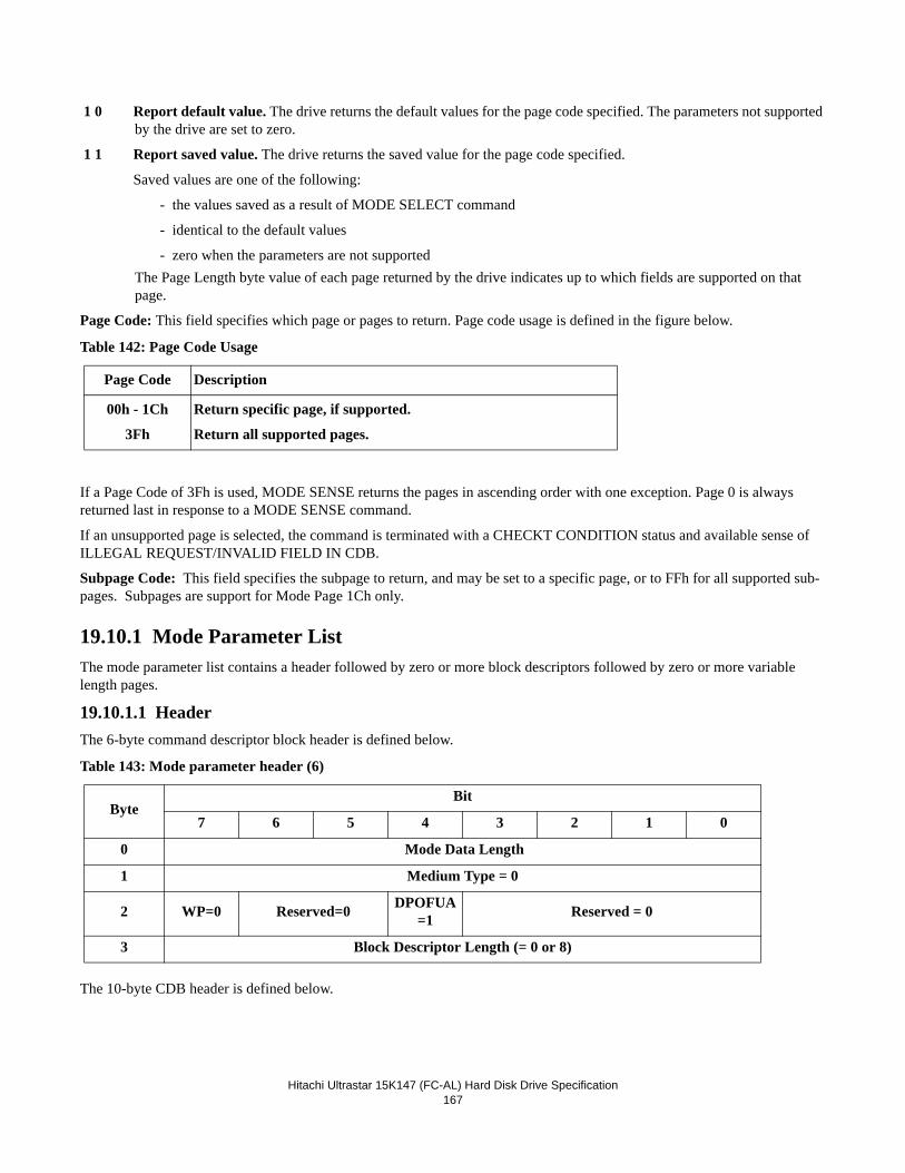
Hitachi Ultrastar 15K147 (FC-AL) Hard Disk Drive Specification
167
1 0 Report default value. The drive returns the default values for the page code specified. The parameters not supported by the drive are set to zero.
1 1 Report saved value. The drive returns the saved value for the page code specified.
Saved values are one of the following:
- the values saved as a result of MODE SELECT command
- identical to the default values
- zero when the parameters are not supportedThe Page Length byte value of each page returned by the drive indicates up to which fields are supported on that page.
Page Code: This field specifies which page or pages to return. Page code usage is defined in the figure below.
Table 142: Page Code Usage
If a Page Code of 3Fh is used, MODE SENSE returns the pages in ascending order with one exception. Page 0 is always returned last in response to a MODE SENSE command.
If an unsupported page is selected, the command is terminated with a CHECKT CONDITION status and available sense of ILLEGAL REQUEST/INVALID FIELD IN CDB.
Subpage Code: This field specifies the subpage to return, and may be set to a specific page, or to FFh for all supported sub-pages. Subpages are support for Mode Page 1Ch only.
19.10.1 Mode Parameter ListThe mode parameter list contains a header followed by zero or more block descriptors followed by zero or more variable length pages.
19.10.1.1 HeaderThe 6-byte command descriptor block header is defined below.
Table 143: Mode parameter header (6)
The 10-byte CDB header is defined below.
Page Code Description
00h - 1Ch
3Fh
Return specific page, if supported.
Return all supported pages.
ByteBit
7 6 5 4 3 2 1 0
0 Mode Data Length
1 Medium Type = 0
2 WP=0 Reserved=0 DPOFUA=1 Reserved = 0
3 Block Descriptor Length (= 0 or 8)
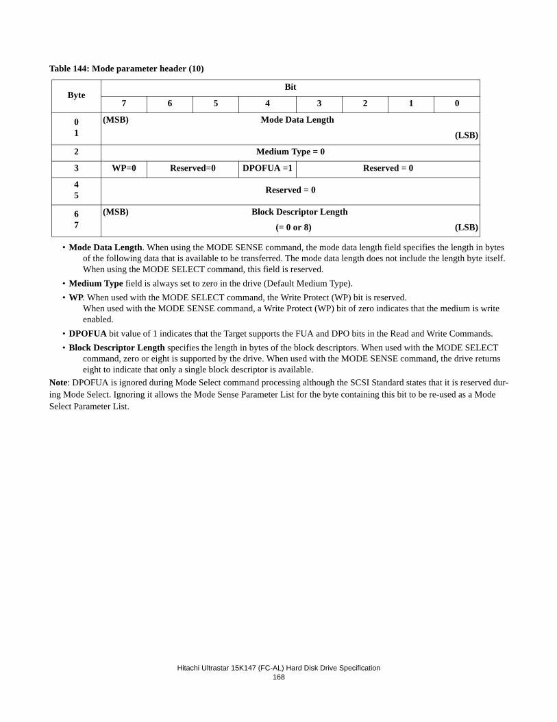
Hitachi Ultrastar 15K147 (FC-AL) Hard Disk Drive Specification
168
Table 144: Mode parameter header (10)
• Mode Data Length. When using the MODE SENSE command, the mode data length field specifies the length in bytes of the following data that is available to be transferred. The mode data length does not include the length byte itself. When using the MODE SELECT command, this field is reserved.
• Medium Type field is always set to zero in the drive (Default Medium Type).• WP. When used with the MODE SELECT command, the Write Protect (WP) bit is reserved.
When used with the MODE SENSE command, a Write Protect (WP) bit of zero indicates that the medium is write enabled.
• DPOFUA bit value of 1 indicates that the Target supports the FUA and DPO bits in the Read and Write Commands.• Block Descriptor Length specifies the length in bytes of the block descriptors. When used with the MODE SELECT
command, zero or eight is supported by the drive. When used with the MODE SENSE command, the drive returns eight to indicate that only a single block descriptor is available.
Note: DPOFUA is ignored during Mode Select command processing although the SCSI Standard states that it is reserved dur-ing Mode Select. Ignoring it allows the Mode Sense Parameter List for the byte containing this bit to be re-used as a Mode Select Parameter List.
ByteBit
7 6 5 4 3 2 1 0
01
(MSB) Mode Data Length
(LSB)
2 Medium Type = 0
3 WP=0 Reserved=0 DPOFUA =1 Reserved = 0
45 Reserved = 0
67
(MSB) Block Descriptor Length
(= 0 or 8) (LSB)
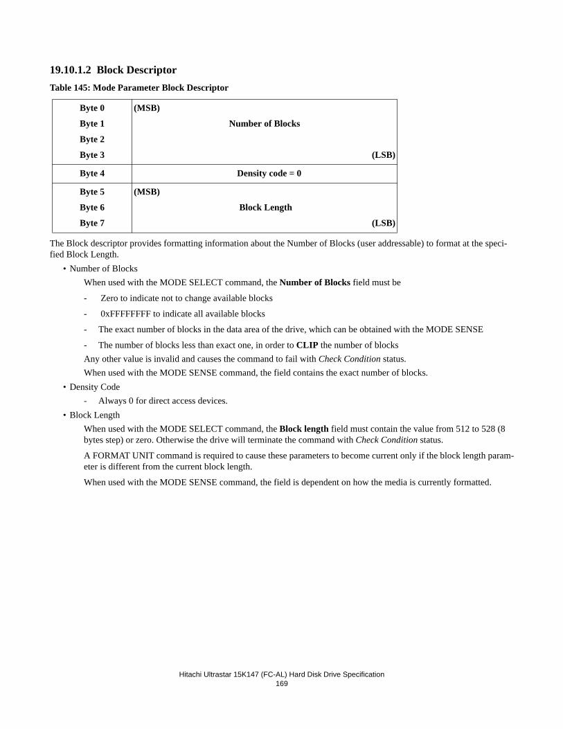
Hitachi Ultrastar 15K147 (FC-AL) Hard Disk Drive Specification
169
19.10.1.2 Block DescriptorTable 145: Mode Parameter Block Descriptor
The Block descriptor provides formatting information about the Number of Blocks (user addressable) to format at the speci-fied Block Length.
• Number of BlocksWhen used with the MODE SELECT command, the Number of Blocks field must be
- Zero to indicate not to change available blocks
- 0xFFFFFFFF to indicate all available blocks
- The exact number of blocks in the data area of the drive, which can be obtained with the MODE SENSE
- The number of blocks less than exact one, in order to CLIP the number of blocksAny other value is invalid and causes the command to fail with Check Condition status.When used with the MODE SENSE command, the field contains the exact number of blocks.
• Density Code- Always 0 for direct access devices.
• Block LengthWhen used with the MODE SELECT command, the Block length field must contain the value from 512 to 528 (8 bytes step) or zero. Otherwise the drive will terminate the command with Check Condition status.
A FORMAT UNIT command is required to cause these parameters to become current only if the block length param-eter is different from the current block length.
When used with the MODE SENSE command, the field is dependent on how the media is currently formatted.
Byte 0
Byte 1
Byte 2
Byte 3
(MSB)
Number of Blocks
(LSB)
Byte 4 Density code = 0
Byte 5
Byte 6
Byte 7
(MSB)
Block Length
(LSB)
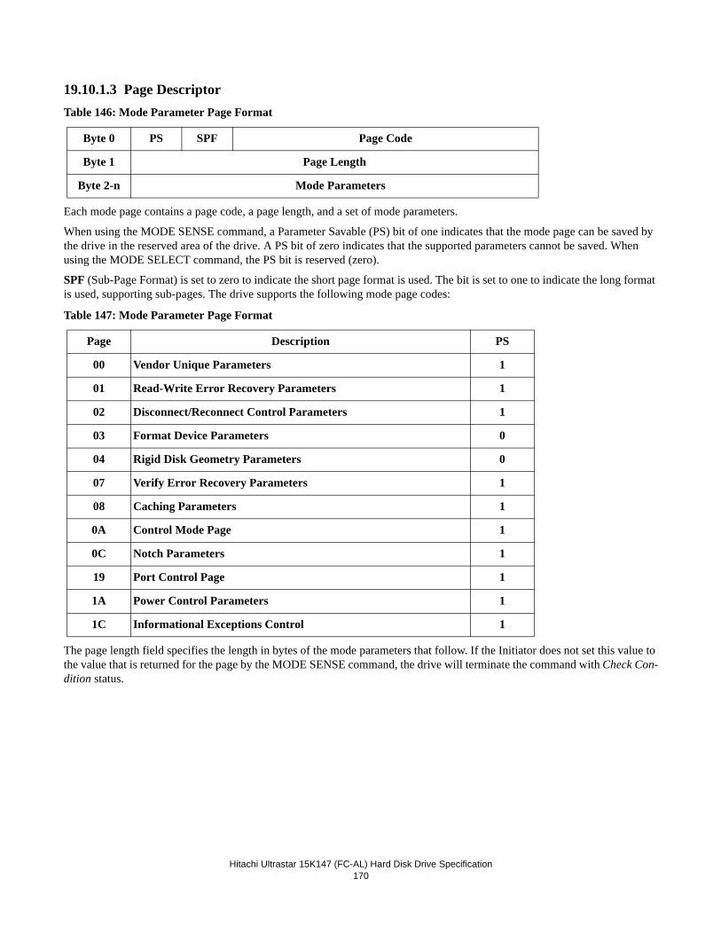
Hitachi Ultrastar 15K147 (FC-AL) Hard Disk Drive Specification
170
19.10.1.3 Page DescriptorTable 146: Mode Parameter Page Format
Each mode page contains a page code, a page length, and a set of mode parameters.
When using the MODE SENSE command, a Parameter Savable (PS) bit of one indicates that the mode page can be saved by the drive in the reserved area of the drive. A PS bit of zero indicates that the supported parameters cannot be saved. When using the MODE SELECT command, the PS bit is reserved (zero).
SPF (Sub-Page Format) is set to zero to indicate the short page format is used. The bit is set to one to indicate the long format is used, supporting sub-pages. The drive supports the following mode page codes:
Table 147: Mode Parameter Page Format
The page length field specifies the length in bytes of the mode parameters that follow. If the Initiator does not set this value to the value that is returned for the page by the MODE SENSE command, the drive will terminate the command with Check Con-dition status.
Byte 0 PS SPF Page Code
Byte 1 Page Length
Byte 2-n Mode Parameters
Page Description PS
00 Vendor Unique Parameters 1
01 Read-Write Error Recovery Parameters 1
02 Disconnect/Reconnect Control Parameters 1
03 Format Device Parameters 0
04 Rigid Disk Geometry Parameters 0
07 Verify Error Recovery Parameters 1
08 Caching Parameters 1
0A Control Mode Page 1
0C Notch Parameters 1
19 Port Control Page 1
1A Power Control Parameters 1
1C Informational Exceptions Control 1
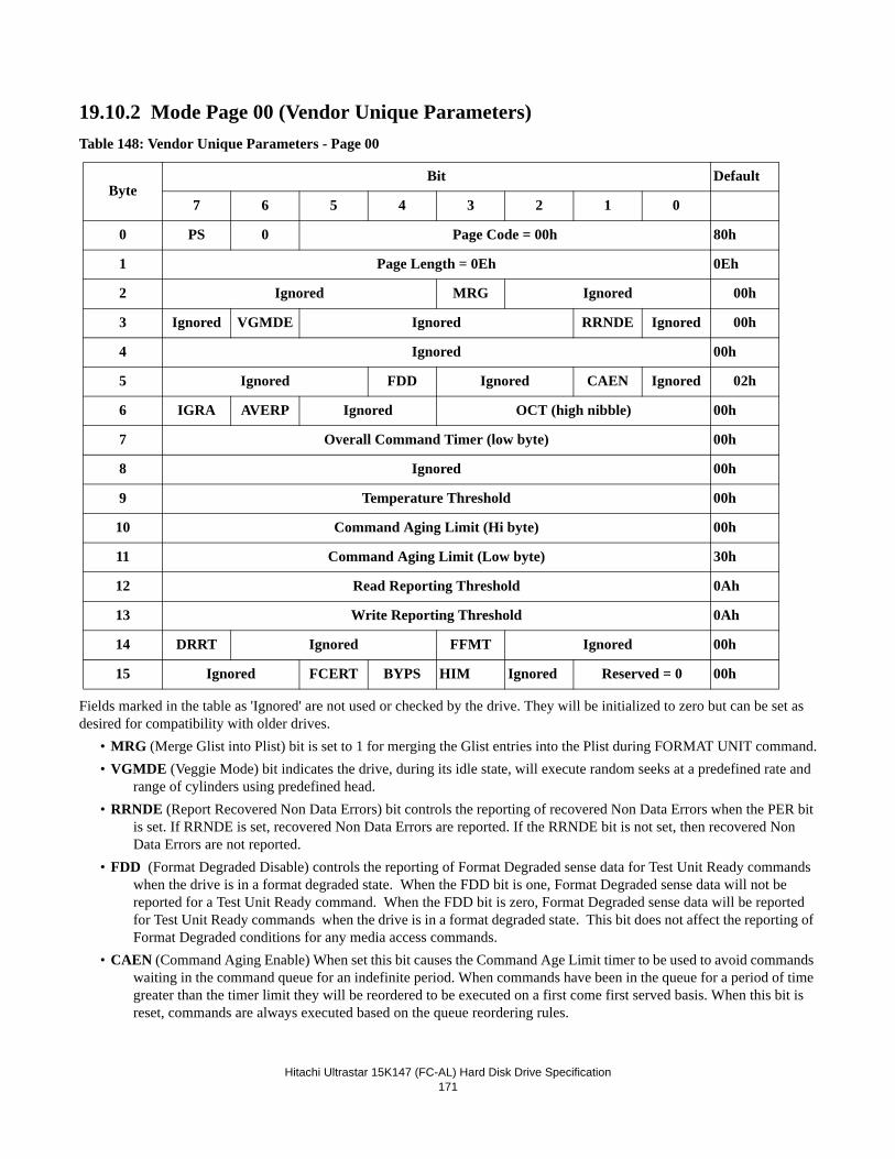
Hitachi Ultrastar 15K147 (FC-AL) Hard Disk Drive Specification
171
19.10.2 Mode Page 00 (Vendor Unique Parameters)Table 148: Vendor Unique Parameters - Page 00
Fields marked in the table as 'Ignored' are not used or checked by the drive. They will be initialized to zero but can be set as desired for compatibility with older drives.
• MRG (Merge Glist into Plist) bit is set to 1 for merging the Glist entries into the Plist during FORMAT UNIT command.• VGMDE (Veggie Mode) bit indicates the drive, during its idle state, will execute random seeks at a predefined rate and
range of cylinders using predefined head. • RRNDE (Report Recovered Non Data Errors) bit controls the reporting of recovered Non Data Errors when the PER bit
is set. If RRNDE is set, recovered Non Data Errors are reported. If the RRNDE bit is not set, then recovered Non Data Errors are not reported.
• FDD (Format Degraded Disable) controls the reporting of Format Degraded sense data for Test Unit Ready commands when the drive is in a format degraded state. When the FDD bit is one, Format Degraded sense data will not be reported for a Test Unit Ready command. When the FDD bit is zero, Format Degraded sense data will be reported for Test Unit Ready commands when the drive is in a format degraded state. This bit does not affect the reporting of Format Degraded conditions for any media access commands.
• CAEN (Command Aging Enable) When set this bit causes the Command Age Limit timer to be used to avoid commands waiting in the command queue for an indefinite period. When commands have been in the queue for a period of time greater than the timer limit they will be reordered to be executed on a first come first served basis. When this bit is reset, commands are always executed based on the queue reordering rules.
ByteBit Default
7 6 5 4 3 2 1 0
0 PS 0 Page Code = 00h 80h
1 Page Length = 0Eh 0Eh
2 Ignored MRG Ignored 00h
3 Ignored VGMDE Ignored RRNDE Ignored 00h
4 Ignored 00h
5 Ignored FDD Ignored CAEN Ignored 02h
6 IGRA AVERP Ignored OCT (high nibble) 00h
7 Overall Command Timer (low byte) 00h
8 Ignored 00h
9 Temperature Threshold 00h
10 Command Aging Limit (Hi byte) 00h
11 Command Aging Limit (Low byte) 30h
12 Read Reporting Threshold 0Ah
13 Write Reporting Threshold 0Ah
14 DRRT Ignored FFMT Ignored 00h
15 Ignored FCERT BYPS HIM Ignored Reserved = 0 00h
Hitachi Ultrastar 15K147 (FC-AL) Hard Disk Drive Specification
172
• IGRA (Ignore Reassigned LBA) bit is set to 1 for preventing the drive from reassigned processing against reassigned LBA when RC bit (Mode Page 1 byte 2 bit 4) is active. The main purpose of this bit is to avoid undesirable read pro-cessing time delay due to reassigned LBA processing for continuous data availability requirements such as Audio Visual application. IGRA bit set to 0 specifies that the drive shall process reassigned LBA even if RC bit is active.
• AVERP (AV ERP Mode) bit is set to one in order to specify maximum retry counts during Read DRP. When AVERP bit is set to one, the maximum retry counts for read operations is specified by Read Retry Count (Mode Page 1 Byte 3). AVERP bit is set to zero to specify that the drive shall process read DRP up to the default maximum retry count when Read Retry Count is set to a non-zero value.
• OCT (Overall Command Timer) controls the maximum command execution time, from receipt by the drive until status is returned. If the command is unable to complete in the specified amount of time, it will be aborted with Check Con-dition status, Aborted Command sense key. The Overall Command Timer does not alter the behavior of the Com-mand Aging Limit or Recovery Time Limit. Each unit of this timer is 50 milliseconds. Setting the value to zero disabled the feature.
• Temperature Threshold specifies the threshold value in degrees Celsius for the thermal sensor warning message. A value of 0 selects the default value (85 degrees Celsius).
• Command Aging Limit This value controls the maximum time a command should wait in the command queue when the CAEN bit is set. Each unit of this timer is 50 ms.
• Read Reporting Threshold specifies the error reporting threshold for recovered data errors during read operations when PER=1.
• Write Reporting Threshold specifies the error reporting threshold for recovered data errors during write operations when PER=1.
• DRRT (Disable Restore Reassign Target) bit disables the reading and restoration of the target LBA during a Reassign Blocks command. If the DRRT bit is zero, the reassign command attempts to restore the target LBA's data. If the data cannot be restored, the target LBA is reassigned and written with a data pattern of all 00s. If the DRRT bit is one, no attempt is made to restore the target LBA.
• FFMT (Fast Format Enable) bit allows the formatting of the drive without any writes to the customer media. All format operations are allowed including changing block sizes and manipulating defects. The drive will operate normally after a fast format with the following caveat: since no data is written to any customer data blocks as a result of a Fast Format operation, there is a possibility that a read attempt to any particular block (without having previously written to that block) will result in an unrecoverable data error. This will most likely happen if the block size is changed as every LBA will contain data of an incorrect length and apparently an incorrect starting point. It is also possible to generate an uncorrectable data error without changing block sizes if the defect list is shortened and previously bad blocks become visible in the customer address space. Of course ALL DATA ON THE DRIVE WILL BE LOST as the result of any format operation and so any attempt to read blocks which have not been written to will result in unpredictable behavior.
• FCERT (Format Certification) bit determines whether the certification step will be performed during a Format Unit command. FCERT bit set to 0 disables certification. FCERT bit set to 1 enables the certification step.
• BYPS (Bypass) controls the drive's actions following a self-initiated reset. If set, the drive will bypass both ports, and remain bypassed when all reset actions are complete. In this mode, intended for development and qualification use, a power cycle is required to re-establish loop communications. If the BYPS bit is zero, the drive will temporarily bypass both ports during the reset, but enable both when the reset actions are complete. A unit attention condition will be reported to indicate that the self-initiated reset has occurred.
• HIM (High Impedance Mode) bit determines how the drive will communicate with an 8067 compliant enclosure. When this bit is set to one, the drive configures its enclosure services bus drivers tobe standard open collector outputs. When set to zero, the drive will actively drive the bus lines high, rather than rely on an external pull-up resistor.
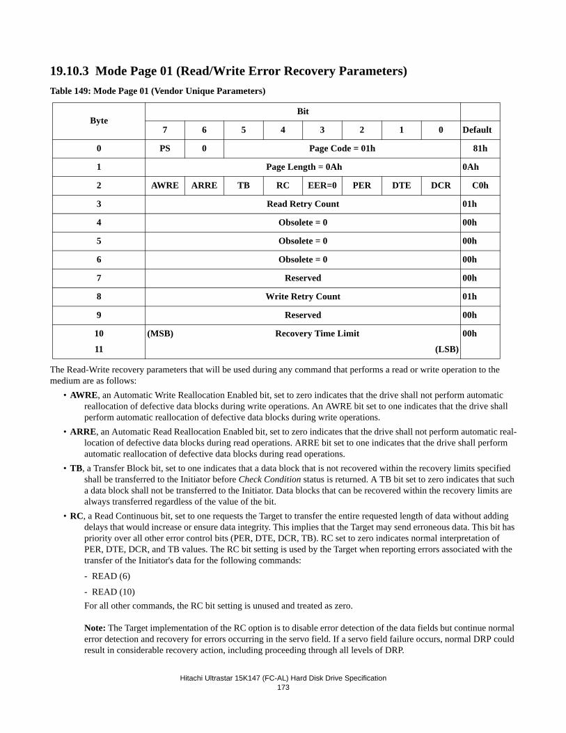
Hitachi Ultrastar 15K147 (FC-AL) Hard Disk Drive Specification
173
19.10.3 Mode Page 01 (Read/Write Error Recovery Parameters)Table 149: Mode Page 01 (Vendor Unique Parameters)
The Read-Write recovery parameters that will be used during any command that performs a read or write operation to the medium are as follows:
• AWRE, an Automatic Write Reallocation Enabled bit, set to zero indicates that the drive shall not perform automatic reallocation of defective data blocks during write operations. An AWRE bit set to one indicates that the drive shall perform automatic reallocation of defective data blocks during write operations.
• ARRE, an Automatic Read Reallocation Enabled bit, set to zero indicates that the drive shall not perform automatic real-location of defective data blocks during read operations. ARRE bit set to one indicates that the drive shall perform automatic reallocation of defective data blocks during read operations.
• TB, a Transfer Block bit, set to one indicates that a data block that is not recovered within the recovery limits specified shall be transferred to the Initiator before Check Condition status is returned. A TB bit set to zero indicates that such a data block shall not be transferred to the Initiator. Data blocks that can be recovered within the recovery limits are always transferred regardless of the value of the bit.
• RC, a Read Continuous bit, set to one requests the Target to transfer the entire requested length of data without adding delays that would increase or ensure data integrity. This implies that the Target may send erroneous data. This bit has priority over all other error control bits (PER, DTE, DCR, TB). RC set to zero indicates normal interpretation of PER, DTE, DCR, and TB values. The RC bit setting is used by the Target when reporting errors associated with the transfer of the Initiator's data for the following commands:
- READ (6)
- READ (10)For all other commands, the RC bit setting is unused and treated as zero.
Note: The Target implementation of the RC option is to disable error detection of the data fields but continue normal error detection and recovery for errors occurring in the servo field. If a servo field failure occurs, normal DRP could result in considerable recovery action, including proceeding through all levels of DRP.
ByteBit
7 6 5 4 3 2 1 0 Default
0 PS 0 Page Code = 01h 81h
1 Page Length = 0Ah 0Ah
2 AWRE ARRE TB RC EER=0 PER DTE DCR C0h
3 Read Retry Count 01h
4 Obsolete = 0 00h
5 Obsolete = 0 00h
6 Obsolete = 0 00h
7 Reserved 00h
8 Write Retry Count 01h
9 Reserved 00h
10
11
(MSB) Recovery Time Limit
(LSB)
00h
Hitachi Ultrastar 15K147 (FC-AL) Hard Disk Drive Specification
174
• EER, an Enable Early Recovery bit, must be set to zero, indicating that the drive shall use an error recovery procedure that minimizes the risk of misdetection or miscorrection during the data transfer. Data shall not be fabricated.
• PER, a Post Error bit, is set to one to indicate that the drive reports recovered errors.• DTE, a Disable Transfer on Error bit, must be set to 0 to indicate that the drive continues the DATA phase upon detec-
tion of a recovered error.• DCR, a Disable Correction bit, is set to one to indicate that Error Correction Code is not used for data error recovery. A
DCR bit of zero indicates that ECC is applied to recover the data.• Read Retry Count sets a limit on the amount of DRP passes in which the Target attempts to recover read errors. A value
of zero disables all data recovery procedures. When AVERP bit (Mode Page 0 Byte 6 Bit 6) is zero, a value of non-zero in Read Retry Count enables all steps of DRP. When AVERP bit is one, the number in Read Retry Count sets the maximum retry count of DRP.
• Write Retry Count sets a limit on the amount of DRP passes in which the Target attempts to recover write errors. A value of zero disables all data recovery procedures..
• Recovery Time Limit indicates the period in 1 millisecond increments for the maximum recovery time of a single LBA. The value must be from 40 ms to 65535 ms (65.5 seconds). The granularity of the timer is 50 ms. If an LBA is not able to be recovered within the limit, a Check Condition will be returned. The Recovery Time Limit will not be applied yo Writes when WCE=1. A value of zero disables the timer.
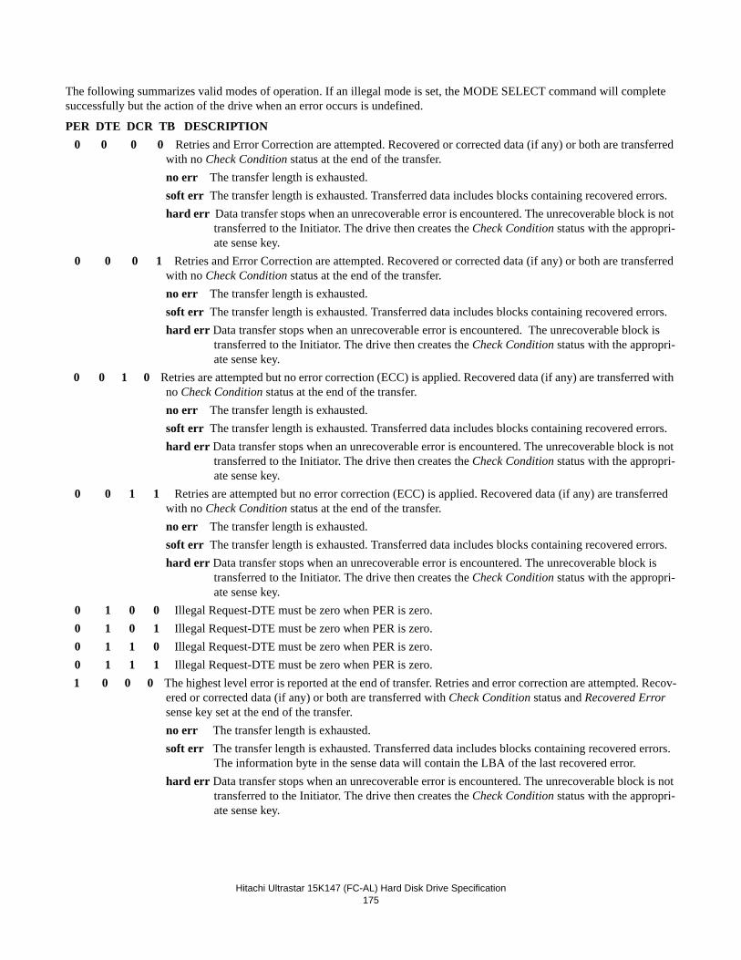
Hitachi Ultrastar 15K147 (FC-AL) Hard Disk Drive Specification
175
The following summarizes valid modes of operation. If an illegal mode is set, the MODE SELECT command will complete successfully but the action of the drive when an error occurs is undefined.
PER DTE DCR TB DESCRIPTION 0 0 0 0 Retries and Error Correction are attempted. Recovered or corrected data (if any) or both are transferred
with no Check Condition status at the end of the transfer.no err The transfer length is exhausted.soft err The transfer length is exhausted. Transferred data includes blocks containing recovered errors.hard err Data transfer stops when an unrecoverable error is encountered. The unrecoverable block is not
transferred to the Initiator. The drive then creates the Check Condition status with the appropri-ate sense key.
0 0 0 1 Retries and Error Correction are attempted. Recovered or corrected data (if any) or both are transferred with no Check Condition status at the end of the transfer.no err The transfer length is exhausted.soft err The transfer length is exhausted. Transferred data includes blocks containing recovered errors.hard err Data transfer stops when an unrecoverable error is encountered. The unrecoverable block is
transferred to the Initiator. The drive then creates the Check Condition status with the appropri-ate sense key.
0 0 1 0 Retries are attempted but no error correction (ECC) is applied. Recovered data (if any) are transferred with no Check Condition status at the end of the transfer.no err The transfer length is exhausted.soft err The transfer length is exhausted. Transferred data includes blocks containing recovered errors.hard err Data transfer stops when an unrecoverable error is encountered. The unrecoverable block is not
transferred to the Initiator. The drive then creates the Check Condition status with the appropri-ate sense key.
0 0 1 1 Retries are attempted but no error correction (ECC) is applied. Recovered data (if any) are transferred with no Check Condition status at the end of the transfer.no err The transfer length is exhausted.soft err The transfer length is exhausted. Transferred data includes blocks containing recovered errors.hard err Data transfer stops when an unrecoverable error is encountered. The unrecoverable block is
transferred to the Initiator. The drive then creates the Check Condition status with the appropri-ate sense key.
0 1 0 0 Illegal Request-DTE must be zero when PER is zero. 0 1 0 1 Illegal Request-DTE must be zero when PER is zero. 0 1 1 0 Illegal Request-DTE must be zero when PER is zero. 0 1 1 1 Illegal Request-DTE must be zero when PER is zero. 1 0 0 0 The highest level error is reported at the end of transfer. Retries and error correction are attempted. Recov-
ered or corrected data (if any) or both are transferred with Check Condition status and Recovered Error sense key set at the end of the transfer.no err The transfer length is exhausted.soft err The transfer length is exhausted. Transferred data includes blocks containing recovered errors.
The information byte in the sense data will contain the LBA of the last recovered error.hard err Data transfer stops when an unrecoverable error is encountered. The unrecoverable block is not
transferred to the Initiator. The drive then creates the Check Condition status with the appropri-ate sense key.
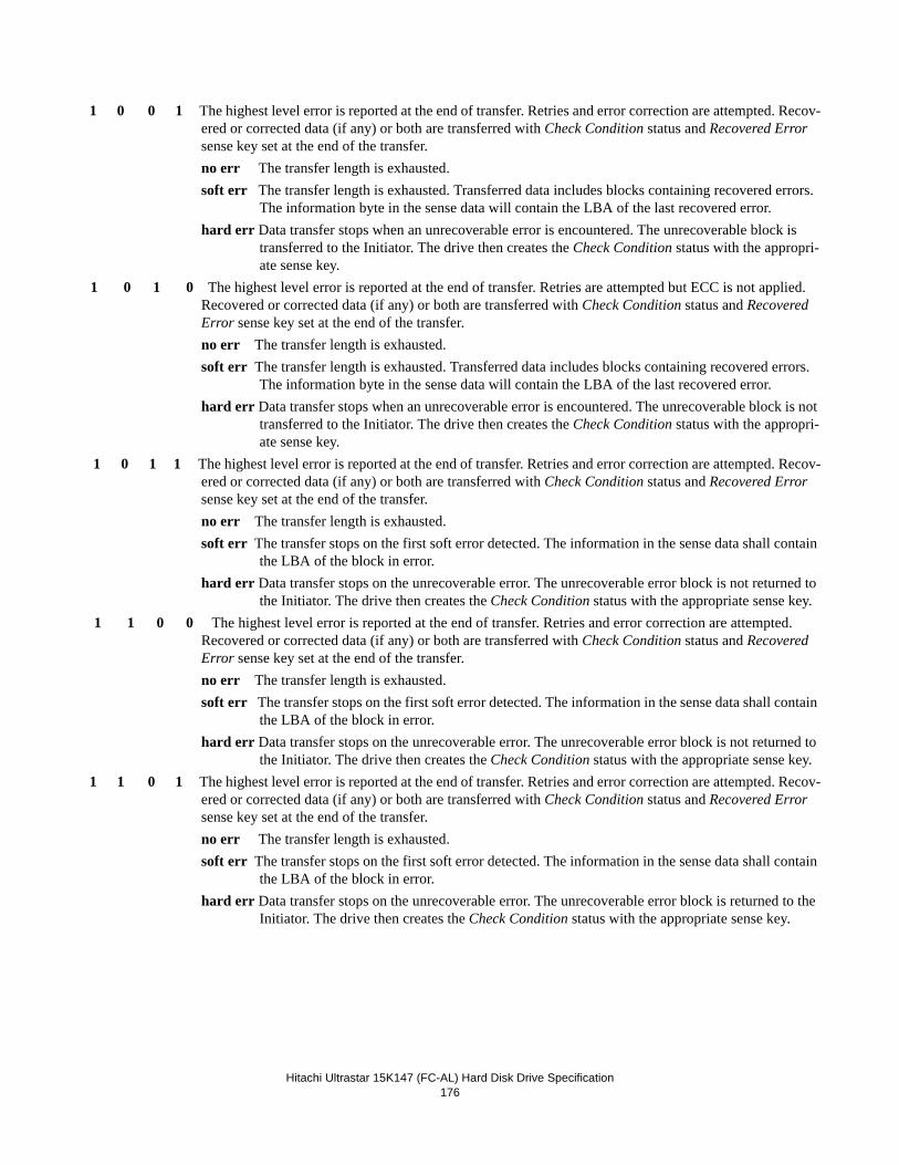
Hitachi Ultrastar 15K147 (FC-AL) Hard Disk Drive Specification
176
1 0 0 1 The highest level error is reported at the end of transfer. Retries and error correction are attempted. Recov-ered or corrected data (if any) or both are transferred with Check Condition status and Recovered Error sense key set at the end of the transfer.no err The transfer length is exhausted.soft err The transfer length is exhausted. Transferred data includes blocks containing recovered errors.
The information byte in the sense data will contain the LBA of the last recovered error.hard err Data transfer stops when an unrecoverable error is encountered. The unrecoverable block is
transferred to the Initiator. The drive then creates the Check Condition status with the appropri-ate sense key.
1 0 1 0 The highest level error is reported at the end of transfer. Retries are attempted but ECC is not applied. Recovered or corrected data (if any) or both are transferred with Check Condition status and Recovered Error sense key set at the end of the transfer.no err The transfer length is exhausted.soft err The transfer length is exhausted. Transferred data includes blocks containing recovered errors.
The information byte in the sense data will contain the LBA of the last recovered error.hard err Data transfer stops when an unrecoverable error is encountered. The unrecoverable block is not
transferred to the Initiator. The drive then creates the Check Condition status with the appropri-ate sense key.
1 0 1 1 The highest level error is reported at the end of transfer. Retries and error correction are attempted. Recov-ered or corrected data (if any) or both are transferred with Check Condition status and Recovered Error sense key set at the end of the transfer.no err The transfer length is exhausted.soft err The transfer stops on the first soft error detected. The information in the sense data shall contain
the LBA of the block in error.hard err Data transfer stops on the unrecoverable error. The unrecoverable error block is not returned to
the Initiator. The drive then creates the Check Condition status with the appropriate sense key. 1 1 0 0 The highest level error is reported at the end of transfer. Retries and error correction are attempted.
Recovered or corrected data (if any) or both are transferred with Check Condition status and Recovered Error sense key set at the end of the transfer.no err The transfer length is exhausted.soft err The transfer stops on the first soft error detected. The information in the sense data shall contain
the LBA of the block in error.hard err Data transfer stops on the unrecoverable error. The unrecoverable error block is not returned to
the Initiator. The drive then creates the Check Condition status with the appropriate sense key. 1 1 0 1 The highest level error is reported at the end of transfer. Retries and error correction are attempted. Recov-
ered or corrected data (if any) or both are transferred with Check Condition status and Recovered Error sense key set at the end of the transfer.no err The transfer length is exhausted.soft err The transfer stops on the first soft error detected. The information in the sense data shall contain
the LBA of the block in error.hard err Data transfer stops on the unrecoverable error. The unrecoverable error block is returned to the
Initiator. The drive then creates the Check Condition status with the appropriate sense key.
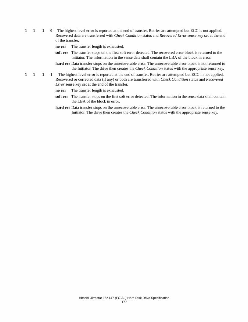
Hitachi Ultrastar 15K147 (FC-AL) Hard Disk Drive Specification
177
1 1 1 0 The highest level error is reported at the end of transfer. Retries are attempted but ECC is not applied. Recovered data are transferred with Check Condition status and Recovered Error sense key set at the end of the transfer.no err The transfer length is exhausted. soft err The transfer stops on the first soft error detected. The recovered error block is returned to the
initiator. The information in the sense data shall contain the LBA of the block in error.hard err Data transfer stops on the unrecoverable error. The unrecoverable error block is not returned to
the Initiator. The drive then creates the Check Condition status with the appropriate sense key. 1 1 1 1 The highest level error is reported at the end of transfer. Retries are attempted but ECC in not applied.
Recovered or corrected data (if any) or both are transferred with Check Condition status and Recovered Error sense key set at the end of the transfer.no err The transfer length is exhausted.soft err The transfer stops on the first soft error detected. The information in the sense data shall contain
the LBA of the block in error.hard err Data transfer stops on the unrecoverable error. The unrecoverable error block is returned to the
Initiator. The drive then creates the Check Condition status with the appropriate sense key.
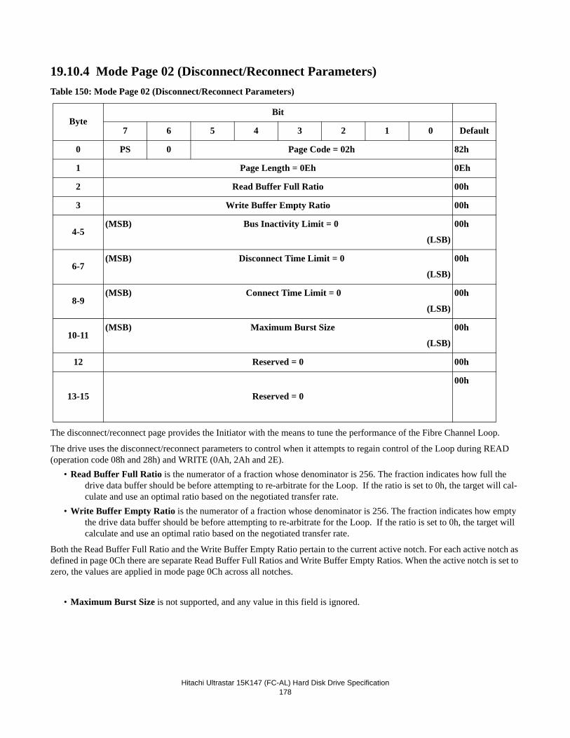
Hitachi Ultrastar 15K147 (FC-AL) Hard Disk Drive Specification
178
19.10.4 Mode Page 02 (Disconnect/Reconnect Parameters)Table 150: Mode Page 02 (Disconnect/Reconnect Parameters)
The disconnect/reconnect page provides the Initiator with the means to tune the performance of the Fibre Channel Loop.
The drive uses the disconnect/reconnect parameters to control when it attempts to regain control of the Loop during READ (operation code 08h and 28h) and WRITE (0Ah, 2Ah and 2E).
• Read Buffer Full Ratio is the numerator of a fraction whose denominator is 256. The fraction indicates how full the drive data buffer should be before attempting to re-arbitrate for the Loop. If the ratio is set to 0h, the target will cal-culate and use an optimal ratio based on the negotiated transfer rate.
• Write Buffer Empty Ratio is the numerator of a fraction whose denominator is 256. The fraction indicates how empty the drive data buffer should be before attempting to re-arbitrate for the Loop. If the ratio is set to 0h, the target will calculate and use an optimal ratio based on the negotiated transfer rate.
Both the Read Buffer Full Ratio and the Write Buffer Empty Ratio pertain to the current active notch. For each active notch as defined in page 0Ch there are separate Read Buffer Full Ratios and Write Buffer Empty Ratios. When the active notch is set to zero, the values are applied in mode page 0Ch across all notches.
• Maximum Burst Size is not supported, and any value in this field is ignored.
ByteBit
7 6 5 4 3 2 1 0 Default
0 PS 0 Page Code = 02h 82h
1 Page Length = 0Eh 0Eh
2 Read Buffer Full Ratio 00h
3 Write Buffer Empty Ratio 00h
4-5(MSB) Bus Inactivity Limit = 0
(LSB)
00h
6-7(MSB) Disconnect Time Limit = 0
(LSB)
00h
8-9(MSB) Connect Time Limit = 0
(LSB)
00h
10-11(MSB) Maximum Burst Size
(LSB)
00h
12 Reserved = 0 00h
13-15 Reserved = 0
00h
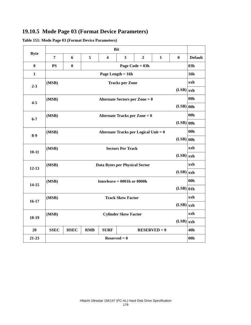
Hitachi Ultrastar 15K147 (FC-AL) Hard Disk Drive Specification
179
19.10.5 Mode Page 03 (Format Device Parameters)Table 151: Mode Page 03 (Format Device Parameters)
ByteBit
7 6 5 4 3 2 1 0 Default
0 PS 0 Page Code = 03h 03h
1 Page Length = 16h 16h
2-3(MSB) Tracks per Zone
(LSB)
xxh
xxh
4-5(MSB) Alternate Sectors per Zone = 0
(LSB)
00h
00h
6-7(MSB) Alternate Tracks per Zone = 0
(LSB)
00h
00h
8-9(MSB) Alternate Tracks per Logical Unit = 0
(LSB)
00h
00h
10-11(MSB) Sectors Per Track
(LSB)
xxh
xxh
12-13(MSB) Data Bytes per Physical Sector
(LSB)
xxh
xxh
14-15(MSB) Interleave = 0001h or 0000h
(LSB)
00h
01h
16-17(MSB) Track Skew Factor
(LSB)
xxh
xxh
18-19(MSB) Cylinder Skew Factor
(LSB)
xxh
xxh
20 SSEC HSEC RMB SURF RESERVED = 0 40h
21-23 Reserved = 0 00h
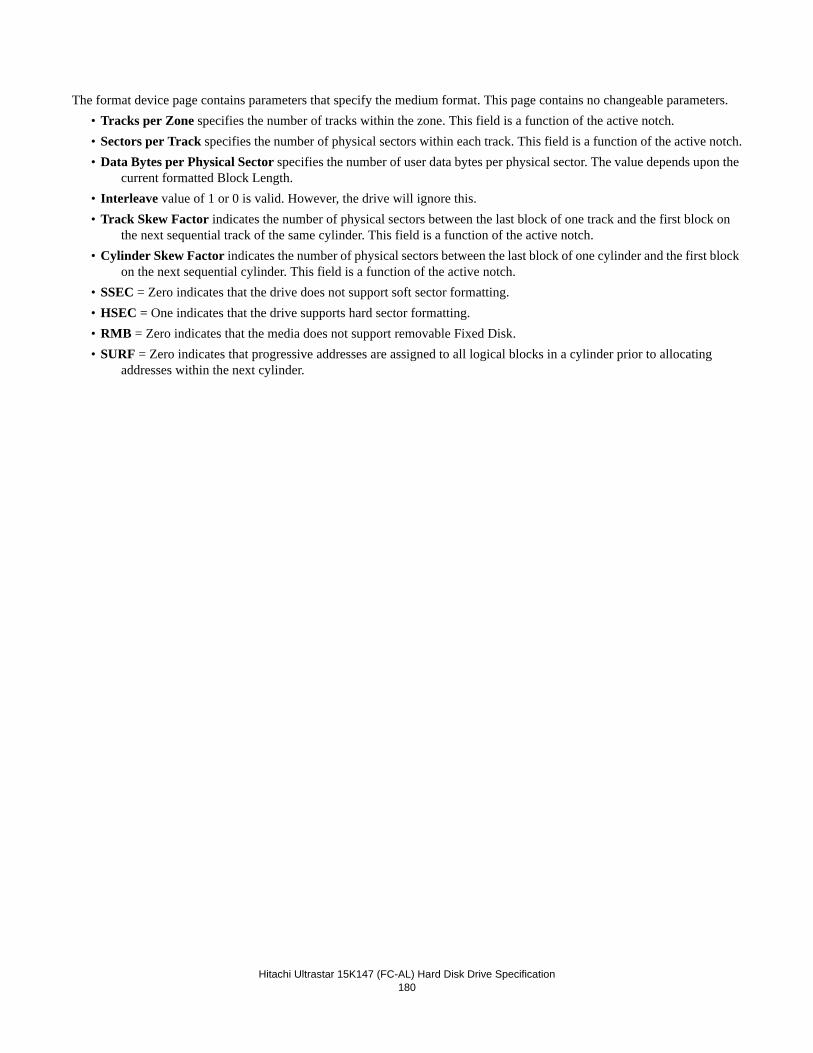
Hitachi Ultrastar 15K147 (FC-AL) Hard Disk Drive Specification
180
The format device page contains parameters that specify the medium format. This page contains no changeable parameters.• Tracks per Zone specifies the number of tracks within the zone. This field is a function of the active notch.• Sectors per Track specifies the number of physical sectors within each track. This field is a function of the active notch.• Data Bytes per Physical Sector specifies the number of user data bytes per physical sector. The value depends upon the
current formatted Block Length.• Interleave value of 1 or 0 is valid. However, the drive will ignore this.• Track Skew Factor indicates the number of physical sectors between the last block of one track and the first block on
the next sequential track of the same cylinder. This field is a function of the active notch.• Cylinder Skew Factor indicates the number of physical sectors between the last block of one cylinder and the first block
on the next sequential cylinder. This field is a function of the active notch.• SSEC = Zero indicates that the drive does not support soft sector formatting.• HSEC = One indicates that the drive supports hard sector formatting.• RMB = Zero indicates that the media does not support removable Fixed Disk.• SURF = Zero indicates that progressive addresses are assigned to all logical blocks in a cylinder prior to allocating
addresses within the next cylinder.
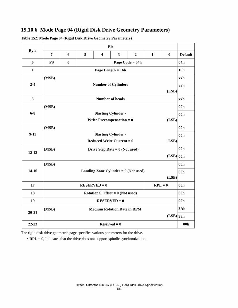
Hitachi Ultrastar 15K147 (FC-AL) Hard Disk Drive Specification
181
19.10.6 Mode Page 04 (Rigid Disk Drive Geometry Parameters)Table 152: Mode Page 04 (Rigid Disk Drive Geometry Parameters)
The rigid disk drive geometric page specifies various parameters for the drive.• RPL = 0, Indicates that the drive does not support spindle synchronization.
ByteBit
7 6 5 4 3 2 1 0 Default
0 PS 0 Page Code = 04h 04h
1 Page Length = 16h 16h
2-4
(MSB)
Number of Cylinders
(LSB)
xxh
xxh
5 Number of heads xxh
6-8
(MSB)
Starting Cylinder -
Write Precompensation = 0 (LSB)
00h
00h
9-11
(MSB)
Starting Cylinder -
Reduced Write Current = 0 LSB)
00h
00h
12-13(MSB) Drive Step Rate = 0 (Not used)
(LSB)
00h
00h
14-16
(MSB)
Landing Zone Cylinder = 0 (Not used)
(LSB)
00h
00h
17 RESERVED = 0 RPL = 0 00h
18 Rotational Offset = 0 (Not used) 00h
19 RESERVED = 0 00h
20-21(MSB) Medium Rotation Rate in RPM
(LSB)
3Ah
98h
22-23 Reserved = 0 00h
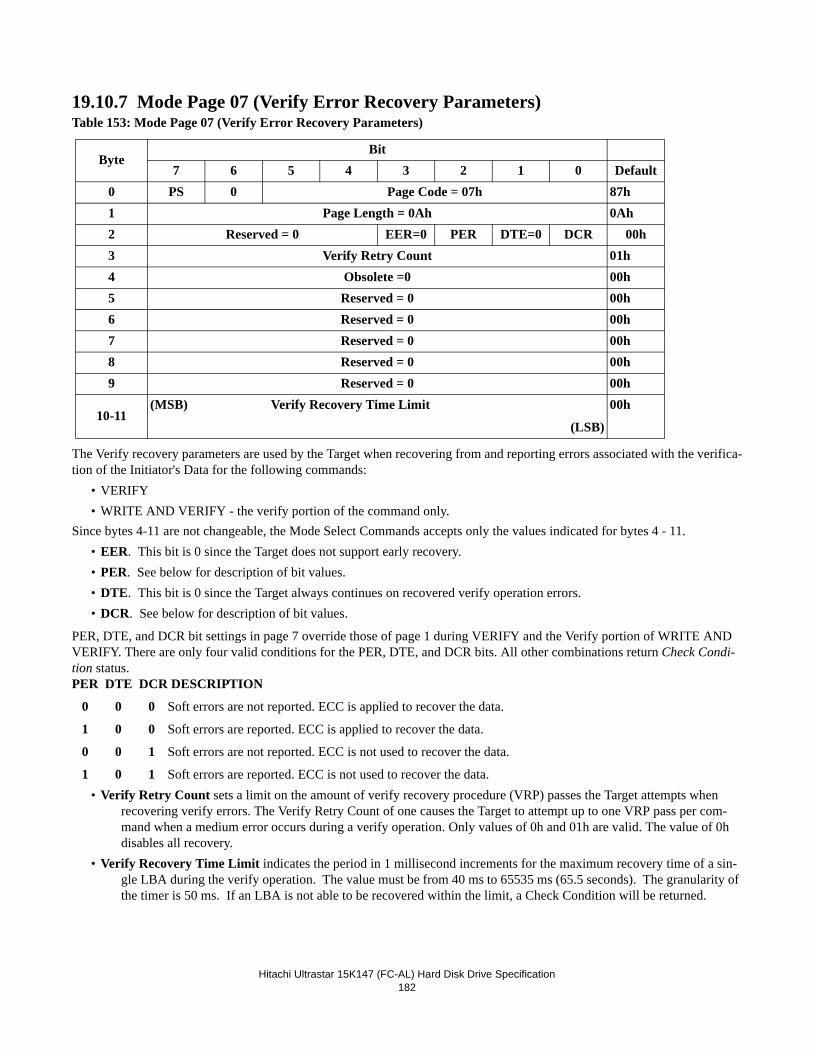
Hitachi Ultrastar 15K147 (FC-AL) Hard Disk Drive Specification
182
19.10.7 Mode Page 07 (Verify Error Recovery Parameters)Table 153: Mode Page 07 (Verify Error Recovery Parameters)
The Verify recovery parameters are used by the Target when recovering from and reporting errors associated with the verifica-tion of the Initiator's Data for the following commands:
• VERIFY• WRITE AND VERIFY - the verify portion of the command only.
Since bytes 4-11 are not changeable, the Mode Select Commands accepts only the values indicated for bytes 4 - 11.• EER. This bit is 0 since the Target does not support early recovery.• PER. See below for description of bit values.• DTE. This bit is 0 since the Target always continues on recovered verify operation errors.• DCR. See below for description of bit values.
PER, DTE, and DCR bit settings in page 7 override those of page 1 during VERIFY and the Verify portion of WRITE AND VERIFY. There are only four valid conditions for the PER, DTE, and DCR bits. All other combinations return Check Condi-tion status.PER DTE DCR DESCRIPTION
0 0 0 Soft errors are not reported. ECC is applied to recover the data.
1 0 0 Soft errors are reported. ECC is applied to recover the data.
0 0 1 Soft errors are not reported. ECC is not used to recover the data.
1 0 1 Soft errors are reported. ECC is not used to recover the data.• Verify Retry Count sets a limit on the amount of verify recovery procedure (VRP) passes the Target attempts when
recovering verify errors. The Verify Retry Count of one causes the Target to attempt up to one VRP pass per com-mand when a medium error occurs during a verify operation. Only values of 0h and 01h are valid. The value of 0h disables all recovery.
• Verify Recovery Time Limit indicates the period in 1 millisecond increments for the maximum recovery time of a sin-gle LBA during the verify operation. The value must be from 40 ms to 65535 ms (65.5 seconds). The granularity of the timer is 50 ms. If an LBA is not able to be recovered within the limit, a Check Condition will be returned.
ByteBit
7 6 5 4 3 2 1 0 Default0 PS 0 Page Code = 07h 87h1 Page Length = 0Ah 0Ah2 Reserved = 0 EER=0 PER DTE=0 DCR 00h3 Verify Retry Count 01h4 Obsolete =0 00h5 Reserved = 0 00h6 Reserved = 0 00h7 Reserved = 0 00h8 Reserved = 0 00h9 Reserved = 0 00h
10-11(MSB) Verify Recovery Time Limit
(LSB)
00h
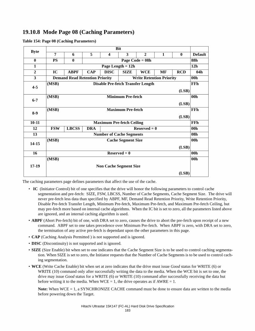
Hitachi Ultrastar 15K147 (FC-AL) Hard Disk Drive Specification
183
19.10.8 Mode Page 08 (Caching Parameters)Table 154: Page 08 (Caching Parameters)
The caching parameters page defines parameters that affect the use of the cache.
• IC (Initiator Control) bit of one specifies that the drive will honor the following parameters to control cache segmentation and pre-fetch: SIZE, FSW, LBCSS, Number of Cache Segments, Cache Segment Size. The drive will never pre-fetch less data than specified by ABPF, MF, Demand Read Retention Priority, Write Retention Priority, Disable Pre-fetch Transfer Length, Minimum Pre-fetch, Maximum Pre-fetch, and Maximum Pre-fetch Ceiling, but may pre-fetch more based on internal cache algorithms. When the IC bit is set to zero, all the parameters listed above are ignored, and an internal caching algorithm is used.
• ABPF (Abort Pre-fetch) bit of one, with DRA set to zero, causes the drive to abort the pre-fetch upon receipt of a new command. ABPF set to one takes precedence over Minimum Pre-fetch. When ABPF is zero, with DRA set to zero, the termination of any active pre-fetch is dependant upon the other parameters in this page.
• CAP (Caching Analysis Permitted ) is not supported and is ignored.• DISC (Discontinuity) is not supported and is ignored.• SIZE (Size Enable) bit when set to one indicates that the Cache Segment Size is to be used to control caching segmenta-
tion. When SIZE is set to zero, the Initiator requests that the Number of Cache Segments is to be used to control cach-ing segmentation.
• WCE (Write Cache Enable) bit when set at zero indicates that the drive must issue Good status for WRITE (6) or WRITE (10) command only after successfully writing the data to the media. When the WCE bit is set to one, the drive may issue Good status for a WRITE (6) or WRITE (10) command after successfully receiving the data but before writing it to the media. When WCE = 1, the drive operates as if AWRE = 1.
Note: When WCE = 1, a SYNCHRONIZE CACHE command must be done to ensure data are written to the media before powering down the Target.
ByteBit
7 6 5 4 3 2 1 0 Default0 PS 0 Page Code = 08h 88h1 Page Length = 12h 12h2 IC ABPF CAP DISC SIZE WCE MF RCD 04h3 Demand Read Retention Priority Write Retention Priority 00h
4-5(MSB) Disable Pre-fetch Transfer Length
(LSB)
FFh
6-7(MSB) Minimum Pre-fetch
(LSB)
00h
8-9(MSB) Maximum Pre-fetch
(LSB)
FFh
10-11 Maximum Pre-fetch Ceiling FFh12 FSW LBCSS DRA Reserved = 0 00h13 Number of Cache Segments 08h
14-15(MSB) Cache Segment Size
(LSB)
00h
16 Reserved = 0 00h
17-19
(MSB)
Non Cache Segment Size
(LSB)
00h
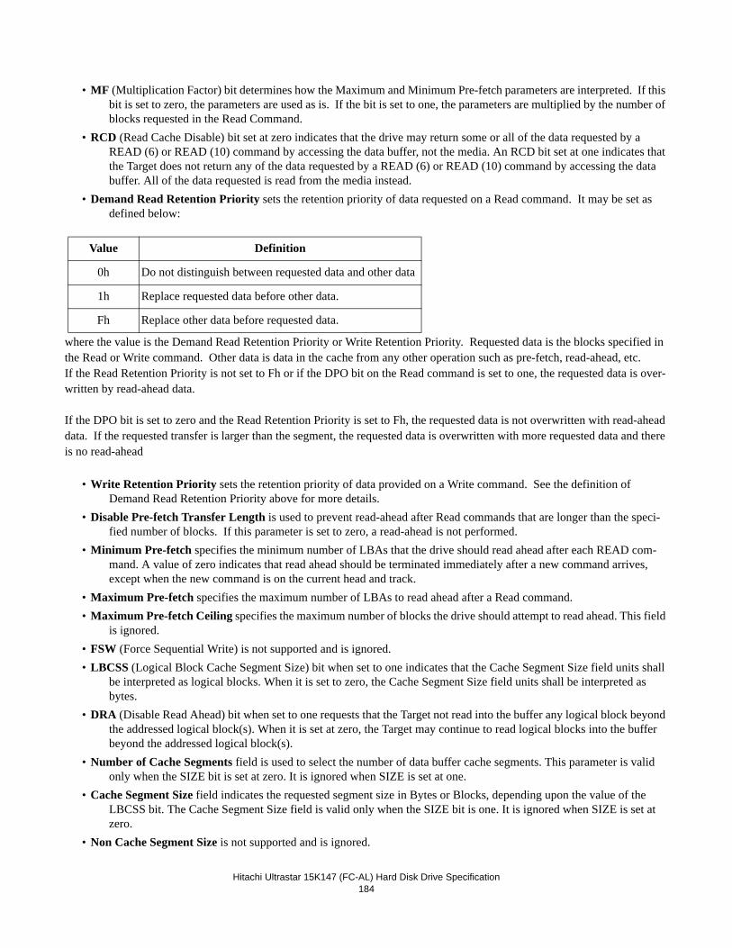
Hitachi Ultrastar 15K147 (FC-AL) Hard Disk Drive Specification
184
• MF (Multiplication Factor) bit determines how the Maximum and Minimum Pre-fetch parameters are interpreted. If this bit is set to zero, the parameters are used as is. If the bit is set to one, the parameters are multiplied by the number of blocks requested in the Read Command.
• RCD (Read Cache Disable) bit set at zero indicates that the drive may return some or all of the data requested by a READ (6) or READ (10) command by accessing the data buffer, not the media. An RCD bit set at one indicates that the Target does not return any of the data requested by a READ (6) or READ (10) command by accessing the data buffer. All of the data requested is read from the media instead.
• Demand Read Retention Priority sets the retention priority of data requested on a Read command. It may be set as defined below:
where the value is the Demand Read Retention Priority or Write Retention Priority. Requested data is the blocks specified in the Read or Write command. Other data is data in the cache from any other operation such as pre-fetch, read-ahead, etc. If the Read Retention Priority is not set to Fh or if the DPO bit on the Read command is set to one, the requested data is over-written by read-ahead data.
If the DPO bit is set to zero and the Read Retention Priority is set to Fh, the requested data is not overwritten with read-ahead data. If the requested transfer is larger than the segment, the requested data is overwritten with more requested data and there is no read-ahead
• Write Retention Priority sets the retention priority of data provided on a Write command. See the definition of Demand Read Retention Priority above for more details.
• Disable Pre-fetch Transfer Length is used to prevent read-ahead after Read commands that are longer than the speci-fied number of blocks. If this parameter is set to zero, a read-ahead is not performed.
• Minimum Pre-fetch specifies the minimum number of LBAs that the drive should read ahead after each READ com-mand. A value of zero indicates that read ahead should be terminated immediately after a new command arrives, except when the new command is on the current head and track.
• Maximum Pre-fetch specifies the maximum number of LBAs to read ahead after a Read command.• Maximum Pre-fetch Ceiling specifies the maximum number of blocks the drive should attempt to read ahead. This field
is ignored.• FSW (Force Sequential Write) is not supported and is ignored.• LBCSS (Logical Block Cache Segment Size) bit when set to one indicates that the Cache Segment Size field units shall
be interpreted as logical blocks. When it is set to zero, the Cache Segment Size field units shall be interpreted as bytes.
• DRA (Disable Read Ahead) bit when set to one requests that the Target not read into the buffer any logical block beyond the addressed logical block(s). When it is set at zero, the Target may continue to read logical blocks into the buffer beyond the addressed logical block(s).
• Number of Cache Segments field is used to select the number of data buffer cache segments. This parameter is valid only when the SIZE bit is set at zero. It is ignored when SIZE is set at one.
• Cache Segment Size field indicates the requested segment size in Bytes or Blocks, depending upon the value of the LBCSS bit. The Cache Segment Size field is valid only when the SIZE bit is one. It is ignored when SIZE is set at zero.
• Non Cache Segment Size is not supported and is ignored.
Value Definition
0h Do not distinguish between requested data and other data
1h Replace requested data before other data.
Fh Replace other data before requested data.
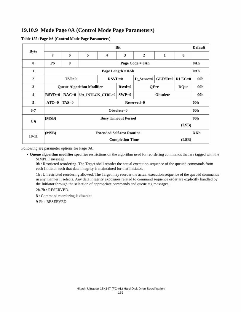
Hitachi Ultrastar 15K147 (FC-AL) Hard Disk Drive Specification
185
19.10.9 Mode Page 0A (Control Mode Page Parameters)Table 155: Page 0A (Control Mode Page Parameters)
Following are parameter options for Page 0A.• Queue algorithm modifier specifies restrictions on the algorithm used for reordering commands that are tagged with the
SIMPLE message.0h : Restricted reordering. The Target shall reorder the actual execution sequence of the queued commands from each Initiator such that data integrity is maintained for that Initiator.1h : Unrestricted reordering allowed. The Target may reorder the actual execution sequence of the queued commands in any manner it selects. Any data integrity exposures related to command sequence order are explicitly handled by the Initiator through the selection of appropriate commands and queue tag messages.2h-7h : RESERVED.8 : Command reordering is disabled9-Fh : RESERVED
ByteBit Default
7 6 5 4 3 2 1 0
0 PS 0 Page Code = 0Ah 8Ah
1 Page Length = 0Ah 0Ah
2 TST=0 RSVD=0 D_Sense=0 GLTSD=0 RLEC=0 00h
3 Queue Algorithm Modifier Rsvd=0 QErr DQue 00h
4 RSVD=0 RAC=0 UA_INTLCK_CTRL=0 SWP=0 Obsolete 00h
5 ATO=0 TAS=0 Reserved=0 00h
6-7 Obsolete=0 00h
8-9(MSB) Busy Timeout Period
(LSB)
00h
10-11(MSB) Extended Self-test Routine
Completion Time (LSB)
XXh
Hitachi Ultrastar 15K147 (FC-AL) Hard Disk Drive Specification
186
• QErr (Queue Error Management) The queue error management (QERR) field specifies how the device server shall han-dle blocked tasks when another task receives a Check Condition status.
• DQue (Disable Queuing) bit set at zero specifies that tagged queuing shall be enabled if the Target supports tagged queu-ing. A DQue bit set at one specifies that tagged queuing shall be disabled. Command queuing is always enabled on the drive, therefore this bit is ignored.
• Busy Timeout Period is ignored internally by the Target.• Extended Self-test Routine Completion Time is an advisory parameter that an Initiator may use to determine the time
in seconds that the Target requires to complete self-test routine when the Target is not interrupted by an Initiator and no errors occur during execution of the self-test routine.
QERR value Description
00b
Specifies that all tasks from all Initiators are blocked from execution when a Contintent Alligience (CA condition) is pending. Those blocked tasks are allowed to resume execution in a normal fashion after the CA condition is cleared.
01b
Specifies that all tasks from all Initiators are aborted when the Target returns Check Con-dition status. A unit attention condition will be generated for each Initiator that had com-mands in the queue except for the Initiator that received the Check Condition status. The sense key will be set to Unit Attention and the additional sense code will be set to Commands Cleared by Another Initiator.
10b Reserved
11b Blocked tasks in the task set belonging to the Initiator to which a Check Condition status is sent shall be aborted when the status is sent.
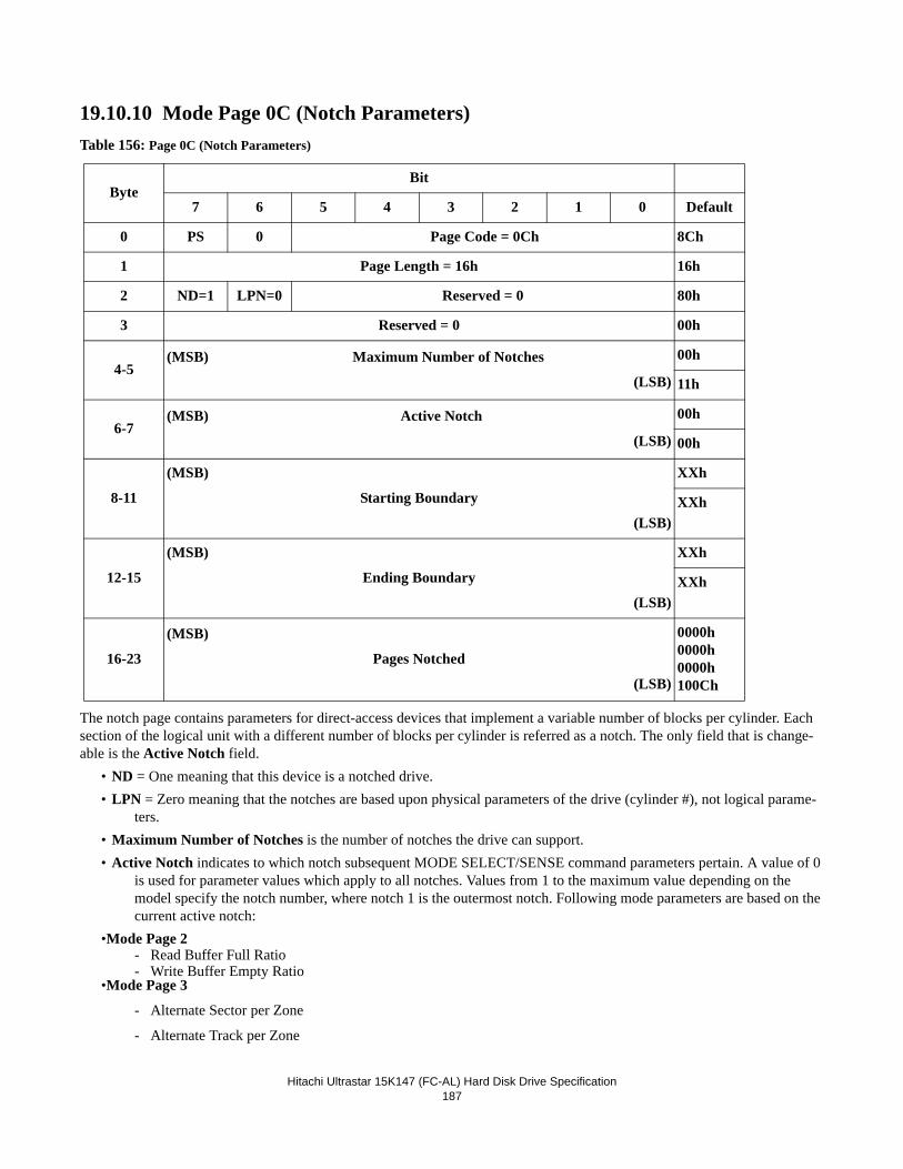
Hitachi Ultrastar 15K147 (FC-AL) Hard Disk Drive Specification
187
19.10.10 Mode Page 0C (Notch Parameters)Table 156: Page 0C (Notch Parameters)
The notch page contains parameters for direct-access devices that implement a variable number of blocks per cylinder. Each section of the logical unit with a different number of blocks per cylinder is referred as a notch. The only field that is change-able is the Active Notch field.
• ND = One meaning that this device is a notched drive.• LPN = Zero meaning that the notches are based upon physical parameters of the drive (cylinder #), not logical parame-
ters.• Maximum Number of Notches is the number of notches the drive can support.• Active Notch indicates to which notch subsequent MODE SELECT/SENSE command parameters pertain. A value of 0
is used for parameter values which apply to all notches. Values from 1 to the maximum value depending on the model specify the notch number, where notch 1 is the outermost notch. Following mode parameters are based on the current active notch:
•Mode Page 2- Read Buffer Full Ratio- Write Buffer Empty Ratio
•Mode Page 3
- Alternate Sector per Zone
- Alternate Track per Zone
ByteBit
7 6 5 4 3 2 1 0 Default
0 PS 0 Page Code = 0Ch 8Ch
1 Page Length = 16h 16h
2 ND=1 LPN=0 Reserved = 0 80h
3 Reserved = 0 00h
4-5(MSB) Maximum Number of Notches
(LSB)
00h
11h
6-7(MSB) Active Notch
(LSB)
00h
00h
8-11
(MSB)
Starting Boundary
(LSB)
XXh
XXh
12-15
(MSB)
Ending Boundary
(LSB)
XXh
XXh
16-23
(MSB)
Pages Notched
(LSB)
0000h0000h0000h100Ch
Hitachi Ultrastar 15K147 (FC-AL) Hard Disk Drive Specification
188
- Alternate Track per Logical Unit
- Sector per Track
- Track Skew Factor
- Cylinder Skew Factor• Starting Boundary contains the first physical location of the active notch. The first three bytes are the cylinder number
and the last byte is the head. The value sent in this field is ignored.• Ending Boundary contains the last physical location of the active notch. The first three bytes are the cylinder number
and the last byte is the head. The value sent in this field is ignored.• Pages Notched is a bit map of the mode page codes that indicates which pages contain parameters that may be different
for different notches. The most significant bit of this field corresponds to page code 3Fh and the least significant bit corresponds to page code 00h. If a bit is one, then the corresponding mode page contains parameters that may be dif-ferent for different notches. If a bit is zero, then the corresponding mode page contains parameters that are constant for all notches.
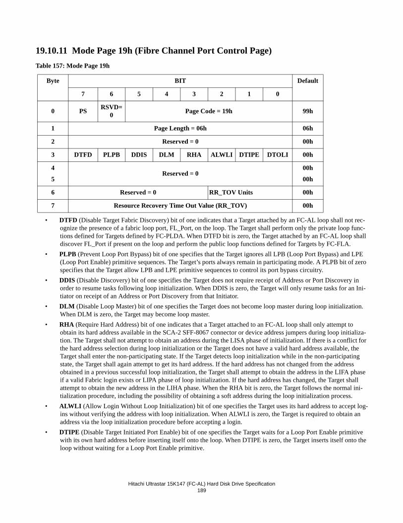
Hitachi Ultrastar 15K147 (FC-AL) Hard Disk Drive Specification
189
19.10.11 Mode Page 19h (Fibre Channel Port Control Page)Table 157: Mode Page 19h
• DTFD (Disable Target Fabric Discovery) bit of one indicates that a Target attached by an FC-AL loop shall not rec-ognize the presence of a fabric loop port, FL_Port, on the loop. The Target shall perform only the private loop func-tions defined for Targets defined by FC-PLDA. When DTFD bit is zero, the Target attached by an FC-AL loop shall discover FL_Port if present on the loop and perform the public loop functions defined for Targets by FC-FLA.
• PLPB (Prevent Loop Port Bypass) bit of one specifies that the Target ignores all LPB (Loop Port Bypass) and LPE (Loop Port Enable) primitive sequences. The Target’s ports always remain in participating mode. A PLPB bit of zero specifies that the Target allow LPB and LPE primitive sequences to control its port bypass circuitry.
• DDIS (Disable Discovery) bit of one specifies the Target does not require receipt of Address or Port Discovery in order to resume tasks following loop initialization. When DDIS is zero, the Target will only resume tasks for an Ini-tiator on receipt of an Address or Port Discovery from that Initiator.
• DLM (Disable Loop Master) bit of one specifies the Target does not become loop master during loop initialization. When DLM is zero, the Target may become loop master.
• RHA (Require Hard Address) bit of one indicates that a Target attached to an FC-AL loop shall only attempt to obtain its hard address available in the SCA-2 SFF-8067 connector or device address jumpers during loop initializa-tion. The Target shall not attempt to obtain an address during the LISA phase of initialization. If there is a conflict for the hard address selection during loop initialization or the Target does not have a valid hard address available, the Target shall enter the non-participating state. If the Target detects loop initialization while in the non-participating state, the Target shall again attempt to get its hard address. If the hard address has not changed from the address obtained in a previous successful loop initialization, the Target shall attempt to obtain the address in the LIFA phase if a valid Fabric login exists or LIPA phase of loop initialization. If the hard address has changed, the Target shall attempt to obtain the new address in the LIHA phase. When the RHA bit is zero, the Target follows the normal ini-tialization procedure, including the possibility of obtaining a soft address during the loop initialization process.
• ALWLI (Allow Login Without Loop Initialization) bit of one specifies the Target uses its hard address to accept log-ins without verifying the address with loop initialization. When ALWLI is zero, the Target is required to obtain an address via the loop initialization procedure before accepting a login.
• DTIPE (Disable Target Initiated Port Enable) bit of one specifies the Target waits for a Loop Port Enable primitive with its own hard address before inserting itself onto the loop. When DTIPE is zero, the Target inserts itself onto the loop without waiting for a Loop Port Enable primitive.
Byte BIT Default
7 6 5 4 3 2 1 0
0 PS RSVD=0 Page Code = 19h 99h
1 Page Length = 06h 06h
2 Reserved = 0 00h
3 DTFD PLPB DDIS DLM RHA ALWLI DTIPE DTOLI 00h
4
5 Reserved = 0
00h
00h
6 Reserved = 0 RR_TOV Units 00h
7 Resource Recovery Time Out Value (RR_TOV) 00h
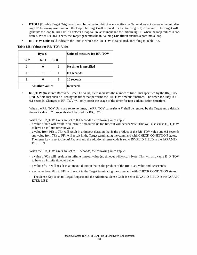
Hitachi Ultrastar 15K147 (FC-AL) Hard Disk Drive Specification
190
• DTOLI (Disable Target Originated Loop Initialization) bit of one specifies the Target does not generate the initializ-ing LIP following insertion into the loop. The Target will respond to an initializing LIP, if received. The Target will generate the loop failure LIP if it detects a loop failure at its input and the initializing LIP when the loop failure is cor-rected. When DTOLI is zero, the Target generates the initializing LIP after it enables a port into a loop.
• RR_TOV Units field indicates the units in which the RR_TOV is calculated, according to Table 158.
Table 158: Values for RR_TOV Units
• RR_TOV (Resource Recovery Time Out Value) field indicates the number of time units specified by the RR_TOV UNITS field that shall be used by the timer that performs the RR_TOV timeout functions. The timer accuracy is +/- 0.1 seconds. Changes to RR_TOV will only affect the usage of the timer for non-authentication situations.
When the RR_TOV Units are set to no timer, the RR_TOV value (byte 7) shall be ignored by the Target and a default timeout value of 2.0 seconds shall be used for RR_TOV.
When the RR_TOV Units are set to 0.1 seconds the following rules apply:- a value of 00h will result in an infinite timeout value (no timeout will occur) Note: This well also cause E_D_TOV
to have an infinite timeout value. - a value from 01h to 7Eh will result in a timeout duration that is the product of the RR_TOV value and 0.1 seconds any value from 7Fh to FFh will result in the Target terminating the command with CHECK CONDITION status.
The sense key is set to Illegal Request and the additional sense code is set to INVALID FIELD in the PARAME-TER LIST.
When the RR_TOV Units are set to 10 seconds, the following rules apply:
- a value of 00h will result in an infinite timeout value (no timeout will occur) Note: This will also cause E_D_TOV to have an infinite timeout value.
- a value of 01h will result in a timeout duration that is the product of the RR_TOV value and 10 seconds
- any value from 02h to FFh will result in the Target terminating the command with CHECK CONDITION status.
- The Sense Key is set to Illegal Request and the Additional Sense Code is set to INVALID FIELD in the PARAM-ETER LIST.
Byte 6 Units of measure for RR_TOV
bit 2 bit 1 bit 0
0 0 0 No timer is specified
0 1 1 0.1 seconds
1 0 1 10 seconds
All other values Reserved
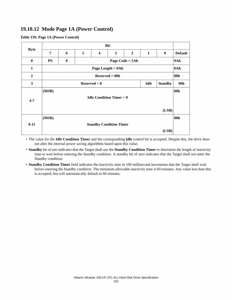
Hitachi Ultrastar 15K147 (FC-AL) Hard Disk Drive Specification
191
19.10.12 Mode Page 1A (Power Control)Table 159: Page 1A (Power Control)
• The value for the Idle Condition Timer and the corresponding Idle control bit is accepted. Despite this, the drive does not alter the internal power saving algorithms based upon this value.
• Standby bit of one indicates that the Target shall use the Standby Condition Timer to determine the length of inactivity time to wait before entering the Standby condition. A standby bit of zero indicates that the Target shall not enter the Standby condition.
• Standby Condition Timer field indicates the inactivity time in 100 millisecond increments that the Target shall wait before entering the Standby condition. The minimum allowable inactivity time is 60 minutes. Any value less than this is accepted, but will automatically default to 60 minutes.
ByteBit
7 6 5 4 3 2 1 0 Default
0 PS 0 Page Code = 1Ah 9Ah
1 Page Length = 0Ah 0Ah
2 Reserved = 00h 00h
3 Reserved = 0 Idle Standby 00h
4-7
(MSB)
Idle Condition Timer = 0
(LSB)
00h
8-11
(MSB)
Standby Condition Timer
(LSB)
00h
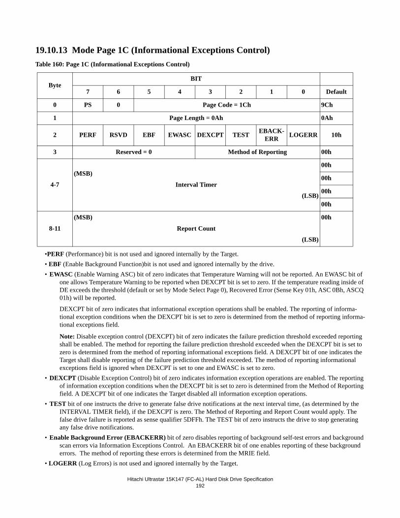
Hitachi Ultrastar 15K147 (FC-AL) Hard Disk Drive Specification
192
19.10.13 Mode Page 1C (Informational Exceptions Control)Table 160: Page 1C (Informational Exceptions Control)
•PERF (Performance) bit is not used and ignored internally by the Target.• EBF (Enable Background Function)bit is not used and ignored internally by the drive.• EWASC (Enable Warning ASC) bit of zero indicates that Temperature Warning will not be reported. An EWASC bit of
one allows Temperature Warning to be reported when DEXCPT bit is set to zero. If the temperature reading inside of DE exceeds the threshold (default or set by Mode Select Page 0), Recovered Error (Sense Key 01h, ASC 0Bh, ASCQ 01h) will be reported.
DEXCPT bit of zero indicates that informational exception operations shall be enabled. The reporting of informa-tional exception conditions when the DEXCPT bit is set to zero is determined from the method of reporting informa-tional exceptions field.
Note: Disable exception control (DEXCPT) bit of zero indicates the failure prediction threshold exceeded reporting shall be enabled. The method for reporting the failure prediction threshold exceeded when the DEXCPT bit is set to zero is determined from the method of reporting informational exceptions field. A DEXCPT bit of one indicates the Target shall disable reporting of the failure prediction threshold exceeded. The method of reporting informational exceptions field is ignored when DEXCPT is set to one and EWASC is set to zero.
• DEXCPT (Disable Exception Control) bit of zero indicates information exception operations are enabled. The reporting of information exception conditions when the DEXCPT bit is set to zero is determined from the Method of Reporting field. A DEXCPT bit of one indicates the Target disabled all information exception operations.
• TEST bit of one instructs the drive to generate false drive notifications at the next interval time, (as determined by the INTERVAL TIMER field), if the DEXCPT is zero. The Method of Reporting and Report Count would apply. The false drive failure is reported as sense qualifier 5DFFh. The TEST bit of zero instructs the drive to stop generating any false drive notifications.
• Enable Background Error (EBACKERR) bit of zero disables reporting of background self-test errors and background scan errors via Information Exceptions Control. An EBACKERR bit of one enables reporting of these background errors. The method of reporting these errors is determined from the MRIE field.
• LOGERR (Log Errors) is not used and ignored internally by the Target.
ByteBIT
7 6 5 4 3 2 1 0 Default
0 PS 0 Page Code = 1Ch 9Ch
1 Page Length = 0Ah 0Ah
2 PERF RSVD EBF EWASC DEXCPT TEST EBACK-ERR LOGERR 10h
3 Reserved = 0 Method of Reporting 00h
4-7
(MSB)
Interval Timer
(LSB)
00h
00h
00h
00h
8-11
(MSB)
Report Count
(LSB)
00h
Hitachi Ultrastar 15K147 (FC-AL) Hard Disk Drive Specification
193
• Method of Reporting Informational Exceptions indicates the methods used by the Target to report informational excep-tion conditions.
Code Description
0h No reporting of informational exception condition: This method instructs the Target to not report infor-mational exception condition.
1h Asynchronous event reporting: Not supported.
2h Generate unit attention: This method instructs the Target to report informational exception conditions by returning a Check Condition status on any command. The sense key is set to Unit Attention and the addi-tional sense code indicates the cause of the informational exception condition. The command that has the Check Condition is not executed before the informational exception condition is reported.
3h Conditionally generate recovered error: This method instructs the Target to report informational excep-tion conditions, dependent on the value of the PER bit of the error recovery parameters mode page, by returning a Check Condition status on any command. The sense key is set to Recovered Error and the addi-tional sense code indicates the cause of the informational exception condition. The command that has the Check Condition completes without error before any informational exception condition is reported.
4h Unconditionally generate recovered error: This method instructs the Target to report informational exception conditions, regardless of the value of the PER bit of the error recovery parameters mode page, by returning a Check Condition status on any command. The sense key is set to Recovered Error and the addi-tional sense code indicates the cause of the informational exception condition. The command that has the Check Condition completes without error before any informational exception condition is reported.
5h Generate no sense: This method instructs the Target to report informational exception conditions by return-ing a Check Condition status on any command. The sense key is set to No Sense and the additional sense code indicates the cause of the informational exception condition. The command that has the Check Condi-tion completes without error before any informational exception condition is reported.
6h Only report informational exception condition on request: This method instructs the Target to preserve the informational exception(s) information. To find out about information exception conditions the Applica-tion Client polls the Target by issuing an unsolicited Request Sense command. The sense key is set to No Sense and the additional sense code indicates the cause of the informational exception condition.
7h-Fh Reserved.• Interval Timer field indicates the period in 100 millisecond increments for reporting that an informational exception
condition has occurred. The target shall not report informational exception conditions more frequently than the time specified by the Interval Timer field and as soon as possible after the time interval has elapsed. After the informa-tional exception condition has been reported the interval timer is restarted. A value of zero or 0xFFFFFFFF in the Interval Timer field indicates that the target only reports the informational exception condition one time and will override the value set in the Report Count field.
• Report Count field indicates the number of times the Target reports an informational exception condition. The Report Count of ZERO indicates no limits on the number of times the Target reports an informational exception condition.
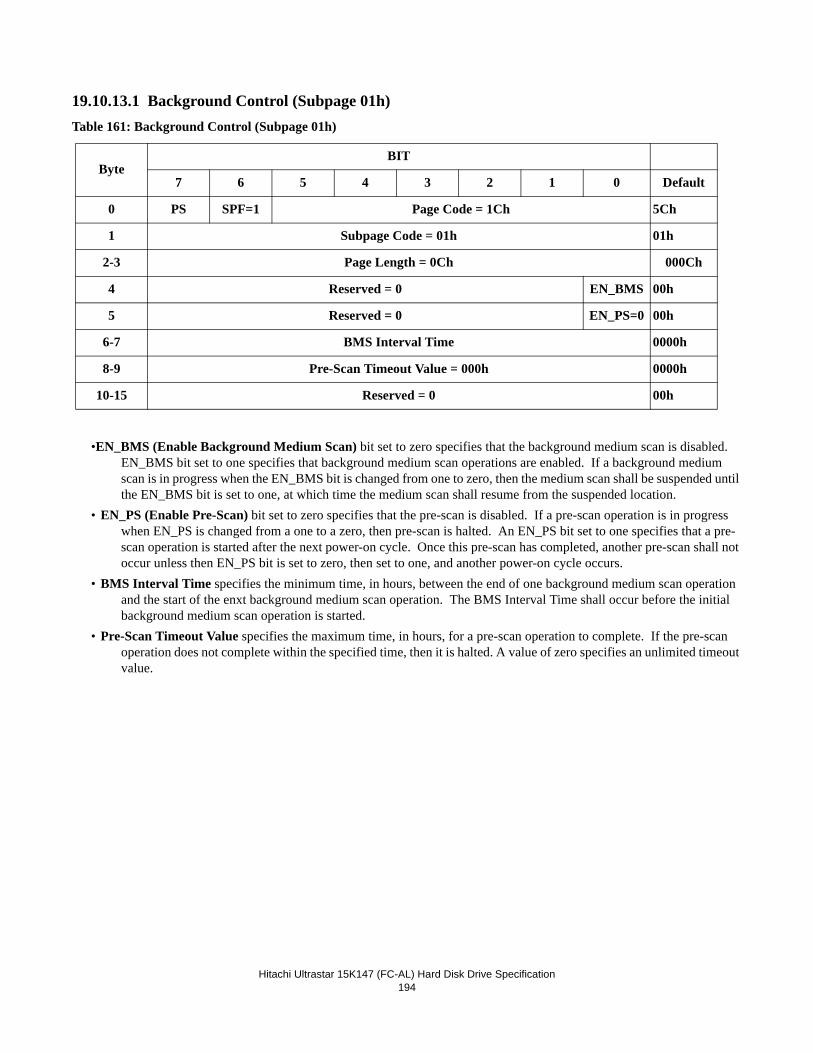
Hitachi Ultrastar 15K147 (FC-AL) Hard Disk Drive Specification
194
19.10.13.1 Background Control (Subpage 01h)Table 161: Background Control (Subpage 01h)
•EN_BMS (Enable Background Medium Scan) bit set to zero specifies that the background medium scan is disabled. EN_BMS bit set to one specifies that background medium scan operations are enabled. If a background medium scan is in progress when the EN_BMS bit is changed from one to zero, then the medium scan shall be suspended until the EN_BMS bit is set to one, at which time the medium scan shall resume from the suspended location.
• EN_PS (Enable Pre-Scan) bit set to zero specifies that the pre-scan is disabled. If a pre-scan operation is in progress when EN_PS is changed from a one to a zero, then pre-scan is halted. An EN_PS bit set to one specifies that a pre-scan operation is started after the next power-on cycle. Once this pre-scan has completed, another pre-scan shall not occur unless then EN_PS bit is set to zero, then set to one, and another power-on cycle occurs.
• BMS Interval Time specifies the minimum time, in hours, between the end of one background medium scan operation and the start of the enxt background medium scan operation. The BMS Interval Time shall occur before the initial background medium scan operation is started.
• Pre-Scan Timeout Value specifies the maximum time, in hours, for a pre-scan operation to complete. If the pre-scan operation does not complete within the specified time, then it is halted. A value of zero specifies an unlimited timeout value.
ByteBIT
7 6 5 4 3 2 1 0 Default
0 PS SPF=1 Page Code = 1Ch 5Ch
1 Subpage Code = 01h 01h
2-3 Page Length = 0Ch 000Ch
4 Reserved = 0 EN_BMS 00h
5 Reserved = 0 EN_PS=0 00h
6-7 BMS Interval Time 0000h
8-9 Pre-Scan Timeout Value = 000h 0000h
10-15 Reserved = 0 00h
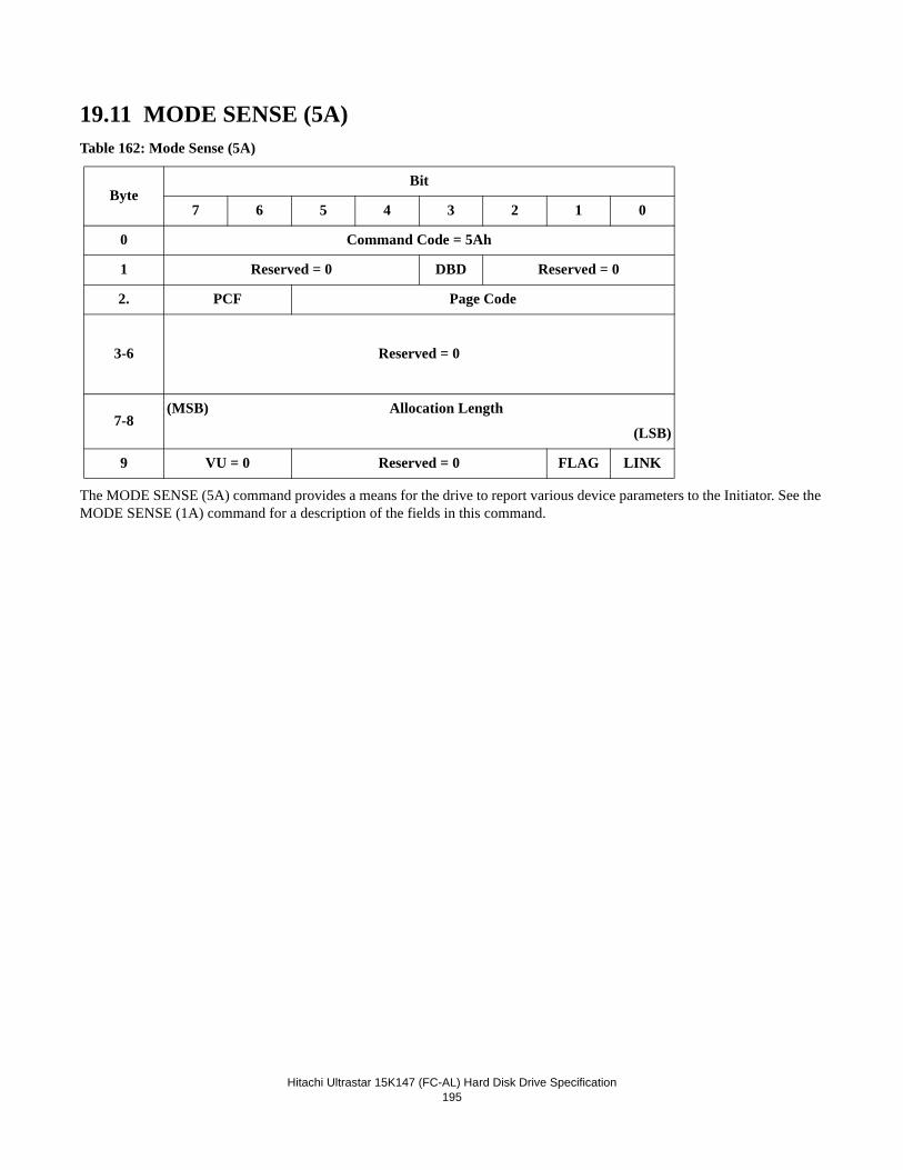
Hitachi Ultrastar 15K147 (FC-AL) Hard Disk Drive Specification
195
19.11 MODE SENSE (5A)Table 162: Mode Sense (5A)
The MODE SENSE (5A) command provides a means for the drive to report various device parameters to the Initiator. See the MODE SENSE (1A) command for a description of the fields in this command.
ByteBit
7 6 5 4 3 2 1 0
0 Command Code = 5Ah
1 Reserved = 0 DBD Reserved = 0
2. PCF Page Code
3-6 Reserved = 0
7-8(MSB) Allocation Length
(LSB)
9 VU = 0 Reserved = 0 FLAG LINK

Hitachi Ultrastar 15K147 (FC-AL) Hard Disk Drive Specification
196
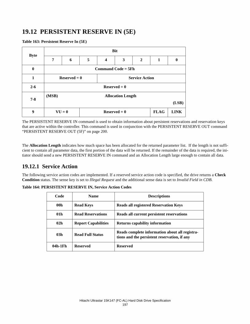
Hitachi Ultrastar 15K147 (FC-AL) Hard Disk Drive Specification197
19.12 PERSISTENT RESERVE IN (5E)Table 163: Persistent Reserve In (5E)
The PERSISTENT RESERVE IN command is used to obtain information about persistent reservations and reservation keys that are active within the controller. This command is used in conjunction with the PERSISTENT RESERVE OUT command “PERSISTENT RESERVE OUT (5F)” on page 200.
The Allocation Length indicates how much space has been allocated for the returned parameter list. If the length is not suffi-cient to contain all parameter data, the first portion of the data will be returned. If the remainder of the data is required, the ini-tiator should send a new PERSISTENT RESERVE IN command and an Allocation Length large enough to contain all data.
19.12.1 Service ActionThe following service action codes are implemented. If a reserved service action code is specified, the drive returns a Check Condition status. The sense key is set to Illegal Request and the additional sense data is set to Invalid Field in CDB.
Table 164: PERSISTENT RESERVE IN, Service Action Codes
ByteBit
7 6 5 4 3 2 1 0
0 Command Code = 5Fh
1 Reserved = 0 Service Action
2-6 Reserved = 0
7-8(MSB) Allocation Length
(LSB)
9 VU = 0 Reserved = 0 FLAG LINK
Code Name Descriptions
00h Read Keys Reads all registered Reservation Keys
01h Read Reservations Reads all current persistent reservations
02h Report Capabilities Returns capability information
03h Read Full Status Reads complete information about all registra-tions and the persistent reservation, if any
04h-1Fh Reserved Reserved
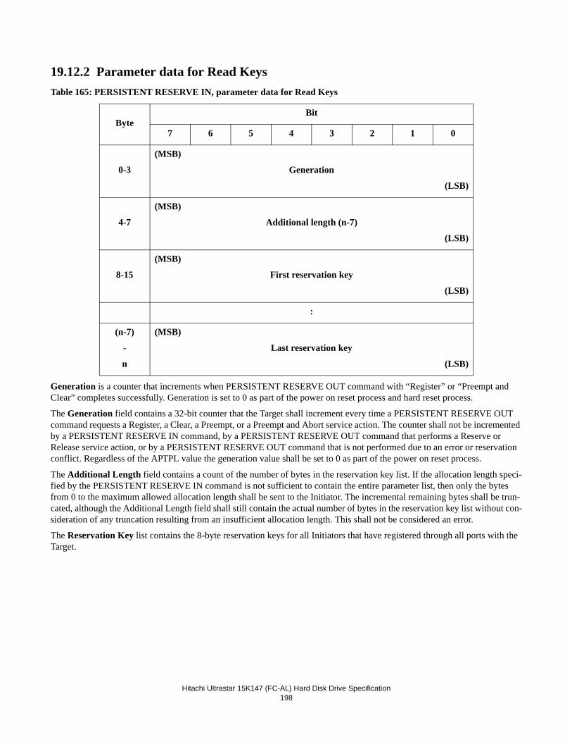
Hitachi Ultrastar 15K147 (FC-AL) Hard Disk Drive Specification198
19.12.2 Parameter data for Read KeysTable 165: PERSISTENT RESERVE IN, parameter data for Read Keys
Generation is a counter that increments when PERSISTENT RESERVE OUT command with “Register” or “Preempt and Clear” completes successfully. Generation is set to 0 as part of the power on reset process and hard reset process.
The Generation field contains a 32-bit counter that the Target shall increment every time a PERSISTENT RESERVE OUT command requests a Register, a Clear, a Preempt, or a Preempt and Abort service action. The counter shall not be incremented by a PERSISTENT RESERVE IN command, by a PERSISTENT RESERVE OUT command that performs a Reserve or Release service action, or by a PERSISTENT RESERVE OUT command that is not performed due to an error or reservation conflict. Regardless of the APTPL value the generation value shall be set to 0 as part of the power on reset process.
The Additional Length field contains a count of the number of bytes in the reservation key list. If the allocation length speci-fied by the PERSISTENT RESERVE IN command is not sufficient to contain the entire parameter list, then only the bytes from 0 to the maximum allowed allocation length shall be sent to the Initiator. The incremental remaining bytes shall be trun-cated, although the Additional Length field shall still contain the actual number of bytes in the reservation key list without con-sideration of any truncation resulting from an insufficient allocation length. This shall not be considered an error.
The Reservation Key list contains the 8-byte reservation keys for all Initiators that have registered through all ports with the Target.
ByteBit
7 6 5 4 3 2 1 0
0-3
(MSB)
Generation
(LSB)
4-7
(MSB)
Additional length (n-7)
(LSB)
8-15
(MSB)
First reservation key
(LSB)
:
(n-7)
-
n
(MSB)
Last reservation key
(LSB)
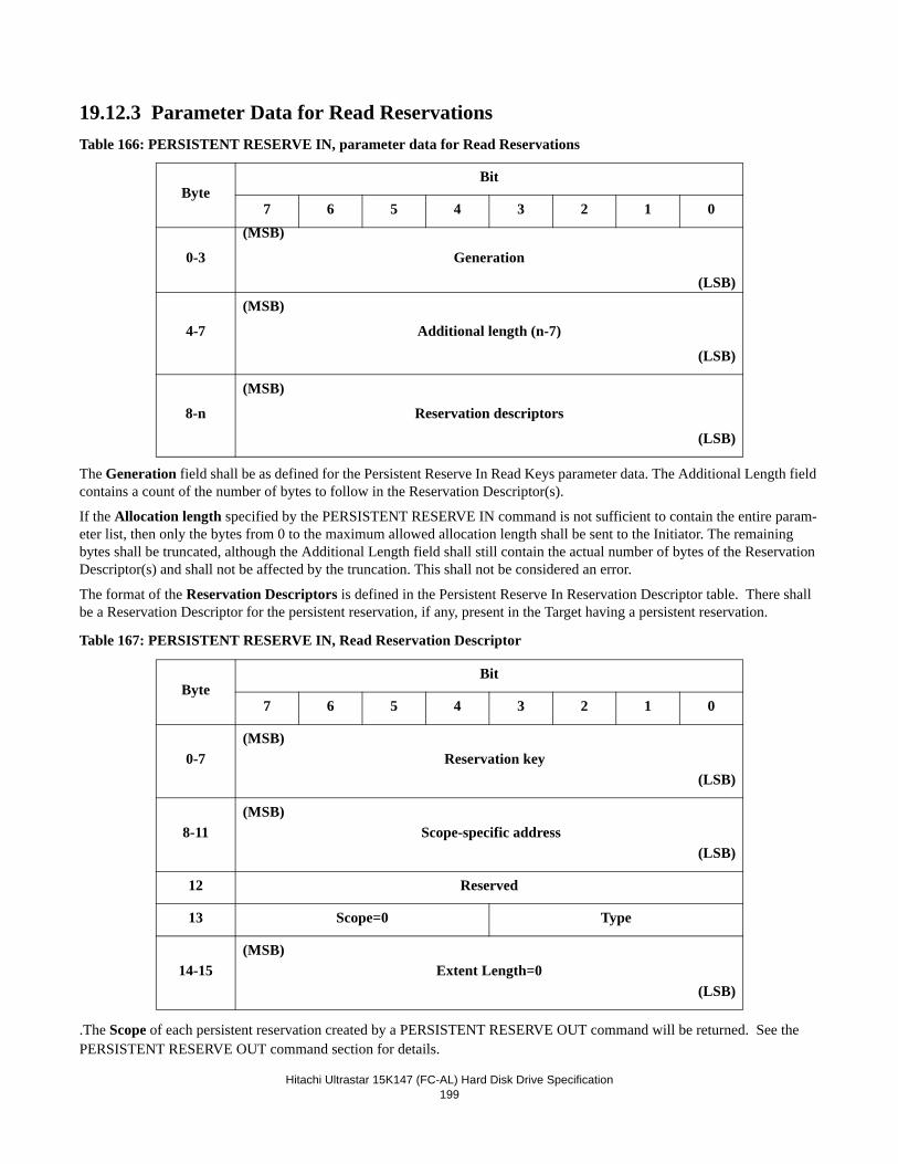
Hitachi Ultrastar 15K147 (FC-AL) Hard Disk Drive Specification199
19.12.3 Parameter Data for Read ReservationsTable 166: PERSISTENT RESERVE IN, parameter data for Read Reservations
The Generation field shall be as defined for the Persistent Reserve In Read Keys parameter data. The Additional Length field contains a count of the number of bytes to follow in the Reservation Descriptor(s).
If the Allocation length specified by the PERSISTENT RESERVE IN command is not sufficient to contain the entire param-eter list, then only the bytes from 0 to the maximum allowed allocation length shall be sent to the Initiator. The remaining bytes shall be truncated, although the Additional Length field shall still contain the actual number of bytes of the Reservation Descriptor(s) and shall not be affected by the truncation. This shall not be considered an error.
The format of the Reservation Descriptors is defined in the Persistent Reserve In Reservation Descriptor table. There shall be a Reservation Descriptor for the persistent reservation, if any, present in the Target having a persistent reservation.
Table 167: PERSISTENT RESERVE IN, Read Reservation Descriptor
.The Scope of each persistent reservation created by a PERSISTENT RESERVE OUT command will be returned. See the PERSISTENT RESERVE OUT command section for details.
ByteBit
7 6 5 4 3 2 1 0
0-3
(MSB)
Generation
(LSB)
4-7
(MSB)
Additional length (n-7)
(LSB)
8-n
(MSB)
Reservation descriptors
(LSB)
ByteBit
7 6 5 4 3 2 1 0
0-7(MSB)
Reservation key(LSB)
8-11(MSB)
Scope-specific address(LSB)
12 Reserved
13 Scope=0 Type
14-15(MSB)
Extent Length=0(LSB)
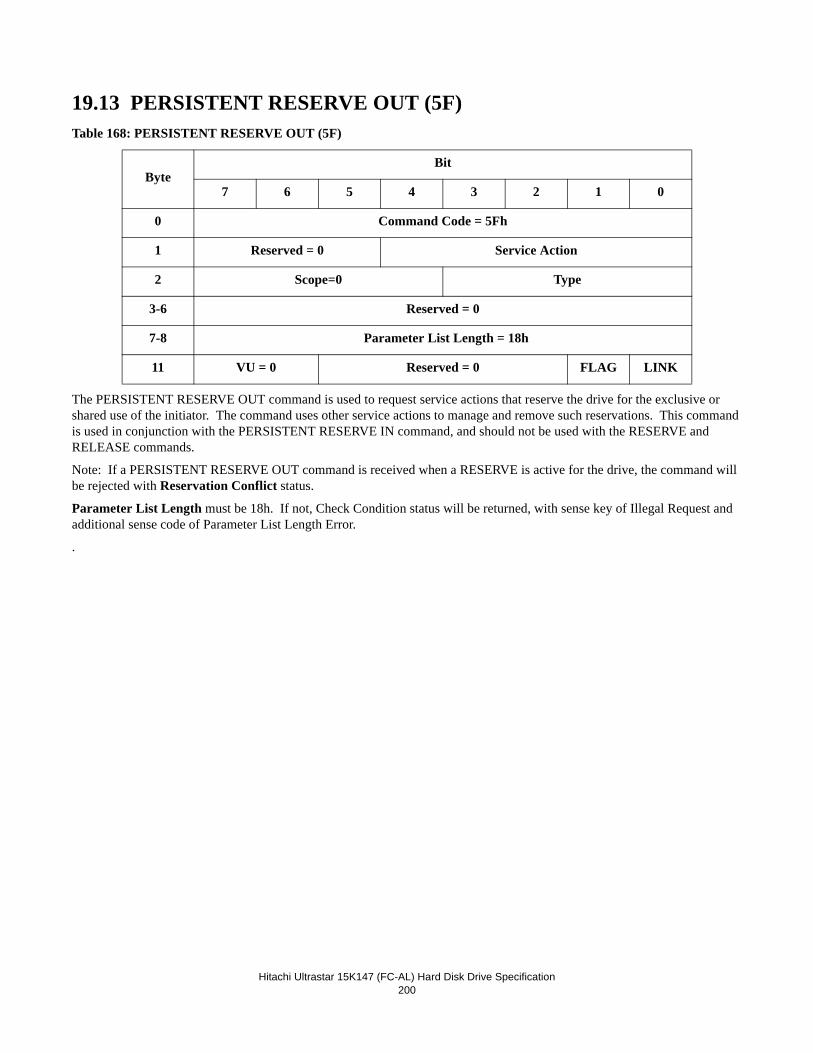
Hitachi Ultrastar 15K147 (FC-AL) Hard Disk Drive Specification200
19.13 PERSISTENT RESERVE OUT (5F)Table 168: PERSISTENT RESERVE OUT (5F)
The PERSISTENT RESERVE OUT command is used to request service actions that reserve the drive for the exclusive or shared use of the initiator. The command uses other service actions to manage and remove such reservations. This command is used in conjunction with the PERSISTENT RESERVE IN command, and should not be used with the RESERVE and RELEASE commands.
Note: If a PERSISTENT RESERVE OUT command is received when a RESERVE is active for the drive, the command will be rejected with Reservation Conflict status.
Parameter List Length must be 18h. If not, Check Condition status will be returned, with sense key of Illegal Request and additional sense code of Parameter List Length Error.
.
ByteBit
7 6 5 4 3 2 1 0
0 Command Code = 5Fh
1 Reserved = 0 Service Action
2 Scope=0 Type
3-6 Reserved = 0
7-8 Parameter List Length = 18h
11 VU = 0 Reserved = 0 FLAG LINK
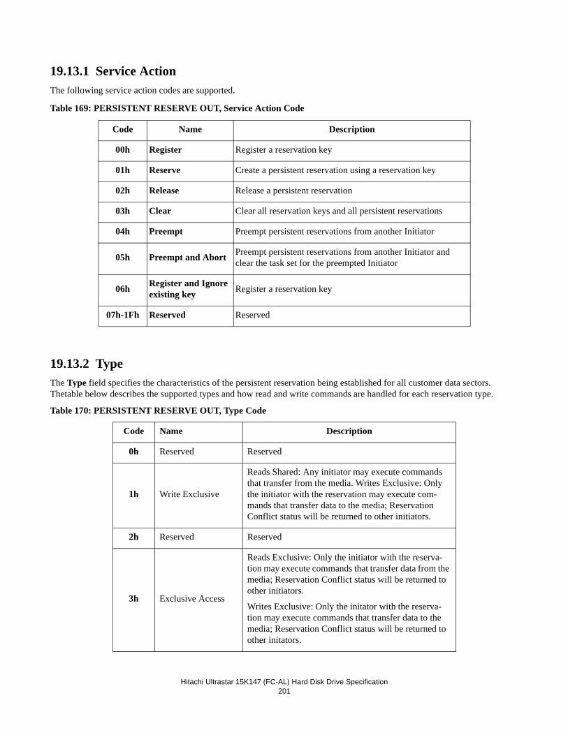
Hitachi Ultrastar 15K147 (FC-AL) Hard Disk Drive Specification201
19.13.1 Service ActionThe following service action codes are supported.
Table 169: PERSISTENT RESERVE OUT, Service Action Code
19.13.2 TypeThe Type field specifies the characteristics of the persistent reservation being established for all customer data sectors. Thetable below describes the supported types and how read and write commands are handled for each reservation type.
Table 170: PERSISTENT RESERVE OUT, Type Code
Code Name Description
00h Register Register a reservation key
01h Reserve Create a persistent reservation using a reservation key
02h Release Release a persistent reservation
03h Clear Clear all reservation keys and all persistent reservations
04h Preempt Preempt persistent reservations from another Initiator
05h Preempt and Abort Preempt persistent reservations from another Initiator and clear the task set for the preempted Initiator
06h Register and Ignore existing key Register a reservation key
07h-1Fh Reserved Reserved
Code Name Description
0h Reserved Reserved
1h Write Exclusive
Reads Shared: Any initiator may execute commands that transfer from the media. Writes Exclusive: Only the initiator with the reservation may execute com-mands that transfer data to the media; Reservation Conflict status will be returned to other initiators.
2h Reserved Reserved
3h Exclusive Access
Reads Exclusive: Only the initiator with the reserva-tion may execute commands that transfer data from the media; Reservation Conflict status will be returned to other initiators.
Writes Exclusive: Only the initator with the reserva-tion may execute commands that transfer data to the media; Reservation Conflict status will be returned to other initators.
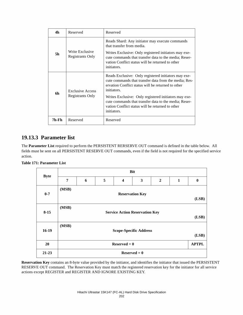
Hitachi Ultrastar 15K147 (FC-AL) Hard Disk Drive Specification202
19.13.3 Parameter listThe Parameter List required to perform the PERSISTENT RERSERVE OUT command is defined in the table below. All fields must be sent on all PERSISTENT RESERVE OUT commands, even if the field is not required for the specified service action.
Table 171: Parameter List
Reservation Key contains an 8-byte value provided by the initiator, and identifies the initiator that issued the PERSISTENT RESERVE OUT command. The Reservation Key must match the registered reservation key for the initiator for all service actions except REGISTER and REGISTER AND IGNORE EXISTING KEY.
4h Reserved Reserved
5h Write Exclusive Registrants Only
Reads Shard: Any initiator may execute commands that transfer from media.
Writes Exclusive: Only registered initiators may exe-cute commands that transfer data to the media; Reser-vation Conflict status will be returned to other initiators.
6h Exclusive Access Registrants Only
Reads Exclusive: Only registered initiators may exe-cute commands that transfer data from the media; Res-ervation Conflict status will be returned to other initiators.
Writes Exclusive: Only registered initiators may exe-cute commands that transfer data to the media; Reser-vation Conflict status will be returned to other initiators.
7h-Fh Reserved Reserved
ByteBit
7 6 5 4 3 2 1 0
0-7(MSB)
Reservation Key(LSB)
8-15(MSB)
Service Action Reservation Key(LSB)
16-19(MSB)
Scope-Specific Address(LSB)
20 Reserved = 0 APTPL
21-23 Reserved = 0
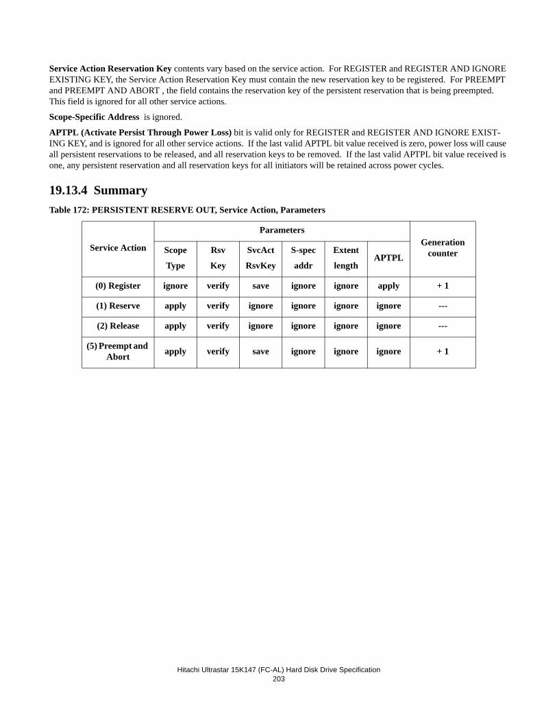
Hitachi Ultrastar 15K147 (FC-AL) Hard Disk Drive Specification203
Service Action Reservation Key contents vary based on the service action. For REGISTER and REGISTER AND IGNORE EXISTING KEY, the Service Action Reservation Key must contain the new reservation key to be registered. For PREEMPT and PREEMPT AND ABORT , the field contains the reservation key of the persistent reservation that is being preempted. This field is ignored for all other service actions.
Scope-Specific Address is ignored.
APTPL (Activate Persist Through Power Loss) bit is valid only for REGISTER and REGISTER AND IGNORE EXIST-ING KEY, and is ignored for all other service actions. If the last valid APTPL bit value received is zero, power loss will cause all persistent reservations to be released, and all reservation keys to be removed. If the last valid APTPL bit value received is one, any persistent reservation and all reservation keys for all initiators will be retained across power cycles.
19.13.4 SummaryTable 172: PERSISTENT RESERVE OUT, Service Action, Parameters
Service Action
ParametersGeneration
counterScope
Type
Rsv
Key
SvcAct
RsvKey
S-spec
addr
Extent
lengthAPTPL
(0) Register ignore verify save ignore ignore apply + 1
(1) Reserve apply verify ignore ignore ignore ignore ---
(2) Release apply verify ignore ignore ignore ignore ---
(5) Preempt and Abort apply verify save ignore ignore ignore + 1
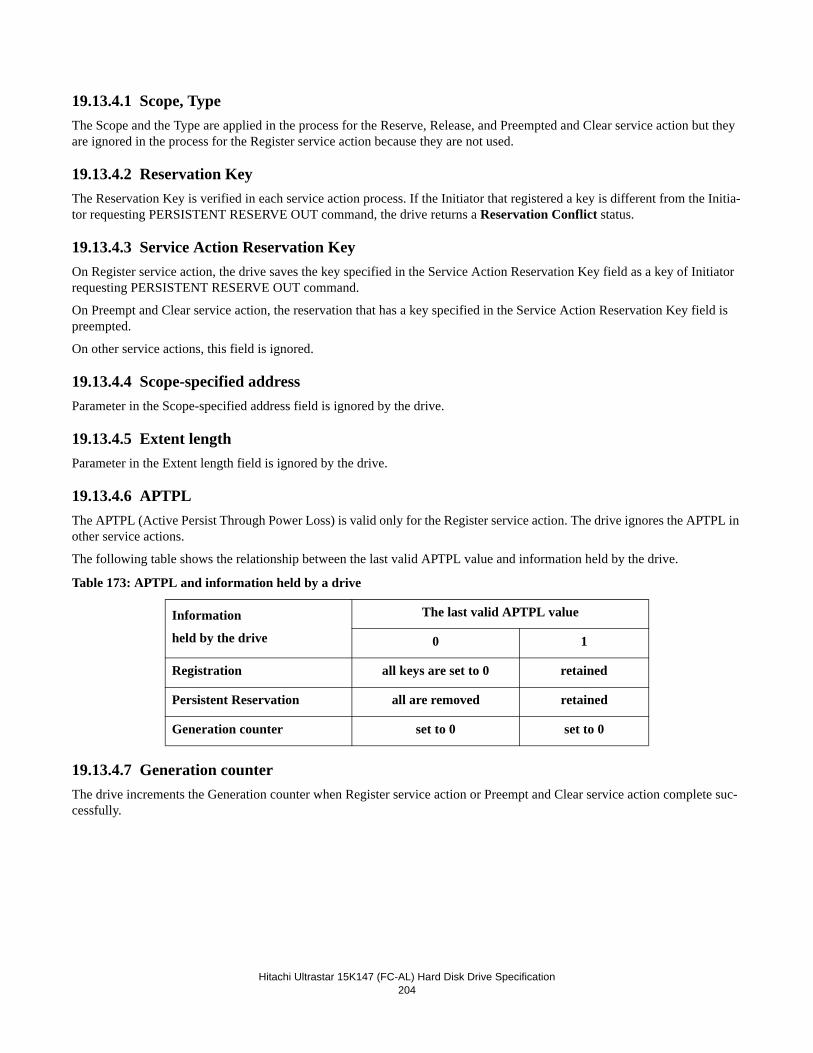
Hitachi Ultrastar 15K147 (FC-AL) Hard Disk Drive Specification204
19.13.4.1 Scope, TypeThe Scope and the Type are applied in the process for the Reserve, Release, and Preempted and Clear service action but they are ignored in the process for the Register service action because they are not used.
19.13.4.2 Reservation KeyThe Reservation Key is verified in each service action process. If the Initiator that registered a key is different from the Initia-tor requesting PERSISTENT RESERVE OUT command, the drive returns a Reservation Conflict status.
19.13.4.3 Service Action Reservation KeyOn Register service action, the drive saves the key specified in the Service Action Reservation Key field as a key of Initiator requesting PERSISTENT RESERVE OUT command.
On Preempt and Clear service action, the reservation that has a key specified in the Service Action Reservation Key field is preempted.
On other service actions, this field is ignored.
19.13.4.4 Scope-specified addressParameter in the Scope-specified address field is ignored by the drive.
19.13.4.5 Extent lengthParameter in the Extent length field is ignored by the drive.
19.13.4.6 APTPLThe APTPL (Active Persist Through Power Loss) is valid only for the Register service action. The drive ignores the APTPL in other service actions.
The following table shows the relationship between the last valid APTPL value and information held by the drive.
Table 173: APTPL and information held by a drive
19.13.4.7 Generation counterThe drive increments the Generation counter when Register service action or Preempt and Clear service action complete suc-cessfully.
Information
held by the drive
The last valid APTPL value
0 1
Registration all keys are set to 0 retained
Persistent Reservation all are removed retained
Generation counter set to 0 set to 0
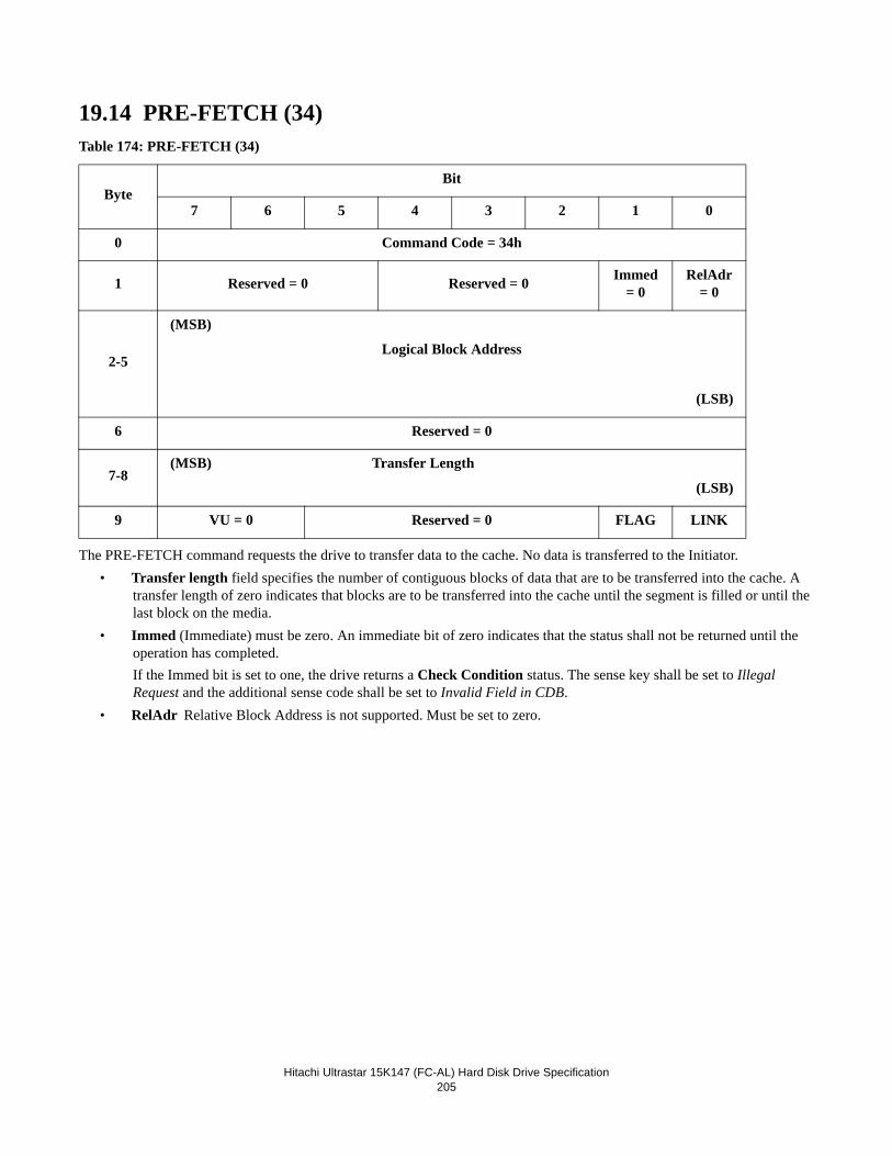
Hitachi Ultrastar 15K147 (FC-AL) Hard Disk Drive Specification205
19.14 PRE-FETCH (34)Table 174: PRE-FETCH (34)
The PRE-FETCH command requests the drive to transfer data to the cache. No data is transferred to the Initiator.• Transfer length field specifies the number of contiguous blocks of data that are to be transferred into the cache. A
transfer length of zero indicates that blocks are to be transferred into the cache until the segment is filled or until the last block on the media.
• Immed (Immediate) must be zero. An immediate bit of zero indicates that the status shall not be returned until the operation has completed. If the Immed bit is set to one, the drive returns a Check Condition status. The sense key shall be set to Illegal Request and the additional sense code shall be set to Invalid Field in CDB.
• RelAdr Relative Block Address is not supported. Must be set to zero.
ByteBit
7 6 5 4 3 2 1 0
0 Command Code = 34h
1 Reserved = 0 Reserved = 0 Immed = 0
RelAdr = 0
2-5
(MSB)
Logical Block Address
(LSB)
6 Reserved = 0
7-8(MSB) Transfer Length
(LSB)
9 VU = 0 Reserved = 0 FLAG LINK
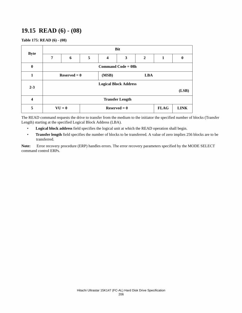
Hitachi Ultrastar 15K147 (FC-AL) Hard Disk Drive Specification206
19.15 READ (6) - (08)Table 175: READ (6) - (08)
The READ command requests the drive to transfer from the medium to the initiator the specified number of blocks (Transfer Length) starting at the specified Logical Block Address (LBA).
• Logical block address field specifies the logical unit at which the READ operation shall begin.• Transfer length field specifies the number of blocks to be transferred. A value of zero implies 256 blocks are to be
transferred.
Note: Error recovery procedure (ERP) handles errors. The error recovery parameters specified by the MODE SELECT command control ERPs.
ByteBit
7 6 5 4 3 2 1 0
0 Command Code = 08h
1 Reserved = 0 (MSB) LBA
2-3Logical Block Address
(LSB)
4 Transfer Length
5 VU = 0 Reserved = 0 FLAG LINK
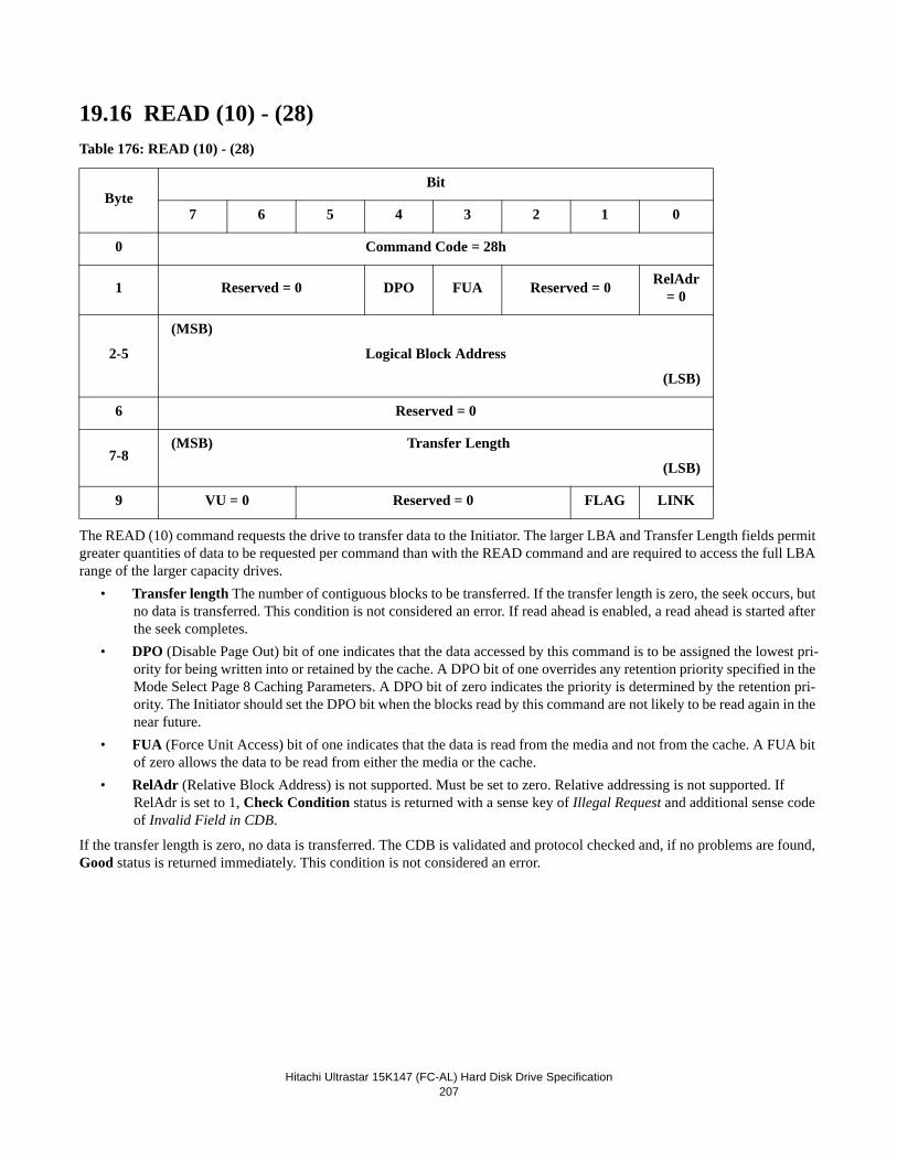
Hitachi Ultrastar 15K147 (FC-AL) Hard Disk Drive Specification207
19.16 READ (10) - (28) Table 176: READ (10) - (28)
The READ (10) command requests the drive to transfer data to the Initiator. The larger LBA and Transfer Length fields permit greater quantities of data to be requested per command than with the READ command and are required to access the full LBA range of the larger capacity drives.
• Transfer length The number of contiguous blocks to be transferred. If the transfer length is zero, the seek occurs, but no data is transferred. This condition is not considered an error. If read ahead is enabled, a read ahead is started after the seek completes.
• DPO (Disable Page Out) bit of one indicates that the data accessed by this command is to be assigned the lowest pri-ority for being written into or retained by the cache. A DPO bit of one overrides any retention priority specified in the Mode Select Page 8 Caching Parameters. A DPO bit of zero indicates the priority is determined by the retention pri-ority. The Initiator should set the DPO bit when the blocks read by this command are not likely to be read again in the near future.
• FUA (Force Unit Access) bit of one indicates that the data is read from the media and not from the cache. A FUA bit of zero allows the data to be read from either the media or the cache.
• RelAdr (Relative Block Address) is not supported. Must be set to zero. Relative addressing is not supported. If RelAdr is set to 1, Check Condition status is returned with a sense key of Illegal Request and additional sense code of Invalid Field in CDB.
If the transfer length is zero, no data is transferred. The CDB is validated and protocol checked and, if no problems are found, Good status is returned immediately. This condition is not considered an error.
ByteBit
7 6 5 4 3 2 1 0
0 Command Code = 28h
1 Reserved = 0 DPO FUA Reserved = 0 RelAdr = 0
2-5
(MSB)
Logical Block Address
(LSB)
6 Reserved = 0
7-8(MSB) Transfer Length
(LSB)
9 VU = 0 Reserved = 0 FLAG LINK
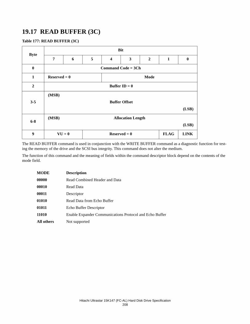
Hitachi Ultrastar 15K147 (FC-AL) Hard Disk Drive Specification208
19.17 READ BUFFER (3C)Table 177: READ BUFFER (3C)
The READ BUFFER command is used in conjunction with the WRITE BUFFER command as a diagnostic function for test-ing the memory of the drive and the SCSI bus integrity. This command does not alter the medium.
The function of this command and the meaning of fields within the command descriptor block depend on the contents of the mode field.
MODE Description
00000 Read Combined Header and Data
00010 Read Data
00011 Descriptor
01010 Read Data from Echo Buffer
01011 Echo Buffer Descriptor
11010 Enable Expander Communications Protocol and Echo Buffer
All others Not supported
ByteBit
7 6 5 4 3 2 1 0
0 Command Code = 3Ch
1 Reserved = 0 Mode
2 Buffer ID = 0
3-5
(MSB)
Buffer Offset
(LSB)
6-8(MSB) Allocation Length
(LSB)
9 VU = 0 Reserved = 0 FLAG LINK
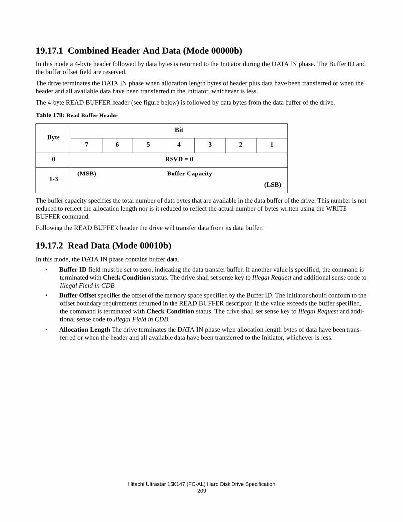
Hitachi Ultrastar 15K147 (FC-AL) Hard Disk Drive Specification209
19.17.1 Combined Header And Data (Mode 00000b)In this mode a 4-byte header followed by data bytes is returned to the Initiator during the DATA IN phase. The Buffer ID and the buffer offset field are reserved.
The drive terminates the DATA IN phase when allocation length bytes of header plus data have been transferred or when the header and all available data have been transferred to the Initiator, whichever is less.
The 4-byte READ BUFFER header (see figure below) is followed by data bytes from the data buffer of the drive.
Table 178: Read Buffer Header
The buffer capacity specifies the total number of data bytes that are available in the data buffer of the drive. This number is not reduced to reflect the allocation length nor is it reduced to reflect the actual number of bytes written using the WRITE BUFFER command.
Following the READ BUFFER header the drive will transfer data from its data buffer.
19.17.2 Read Data (Mode 00010b)In this mode, the DATA IN phase contains buffer data.
• Buffer ID field must be set to zero, indicating the data transfer buffer. If another value is specified, the command is terminated with Check Condition status. The drive shall set sense key to Illegal Request and additional sense code to Illegal Field in CDB.
• Buffer Offset specifies the offset of the memory space specified by the Buffer ID. The Initiator should conform to the offset boundary requirements returned in the READ BUFFER descriptor. If the value exceeds the buffer specified, the command is terminated with Check Condition status. The drive shall set sense key to Illegal Request and addi-tional sense code to Illegal Field in CDB.
• Allocation Length The drive terminates the DATA IN phase when allocation length bytes of data have been trans-ferred or when the header and all available data have been transferred to the Initiator, whichever is less.
ByteBit
7 6 5 4 3 2 1
0 RSVD = 0
1-3(MSB) Buffer Capacity
(LSB)
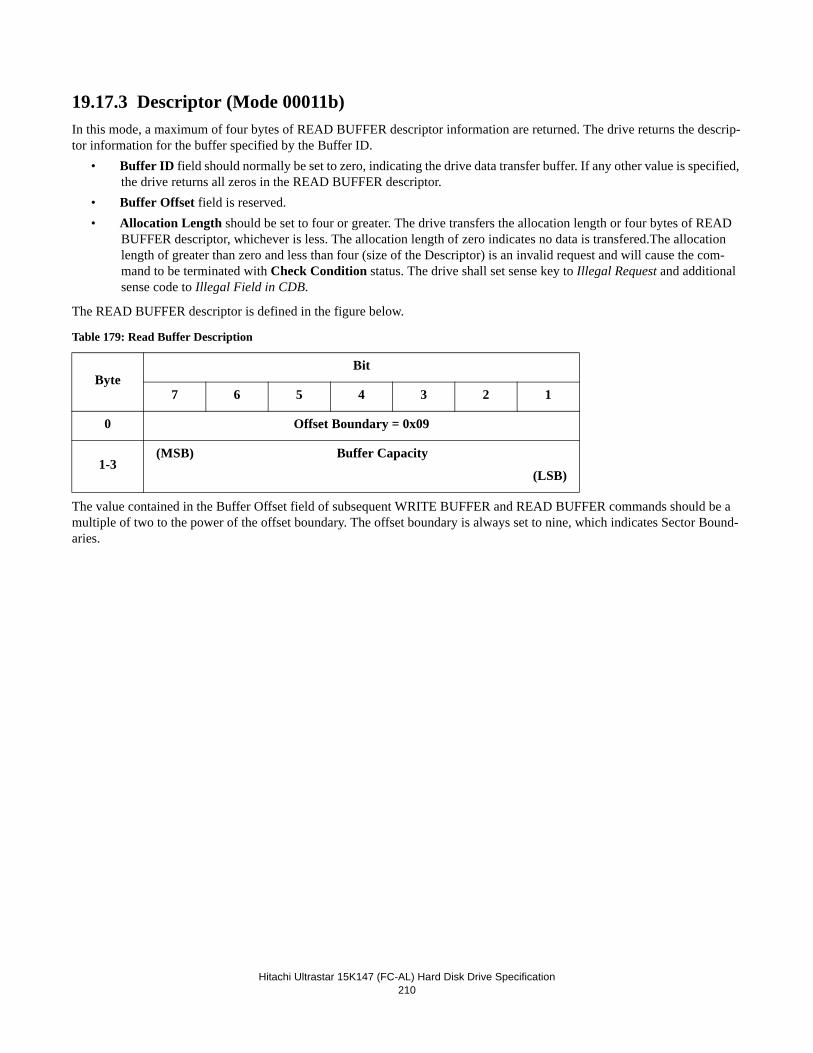
Hitachi Ultrastar 15K147 (FC-AL) Hard Disk Drive Specification210
19.17.3 Descriptor (Mode 00011b)In this mode, a maximum of four bytes of READ BUFFER descriptor information are returned. The drive returns the descrip-tor information for the buffer specified by the Buffer ID.
• Buffer ID field should normally be set to zero, indicating the drive data transfer buffer. If any other value is specified, the drive returns all zeros in the READ BUFFER descriptor.
• Buffer Offset field is reserved.• Allocation Length should be set to four or greater. The drive transfers the allocation length or four bytes of READ
BUFFER descriptor, whichever is less. The allocation length of zero indicates no data is transfered.The allocation length of greater than zero and less than four (size of the Descriptor) is an invalid request and will cause the com-mand to be terminated with Check Condition status. The drive shall set sense key to Illegal Request and additional sense code to Illegal Field in CDB.
The READ BUFFER descriptor is defined in the figure below. Table 179: Read Buffer Description
The value contained in the Buffer Offset field of subsequent WRITE BUFFER and READ BUFFER commands should be a multiple of two to the power of the offset boundary. The offset boundary is always set to nine, which indicates Sector Bound-aries.
ByteBit
7 6 5 4 3 2 1
0 Offset Boundary = 0x09
1-3(MSB) Buffer Capacity
(LSB)
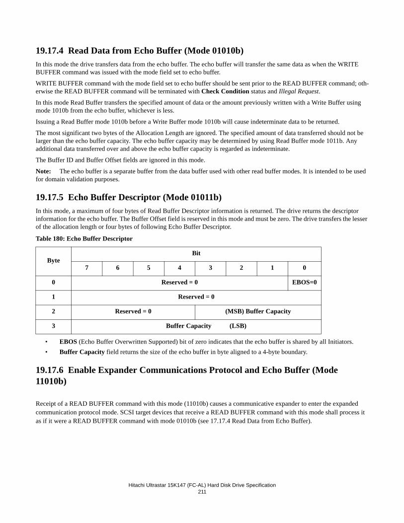
Hitachi Ultrastar 15K147 (FC-AL) Hard Disk Drive Specification211
19.17.4 Read Data from Echo Buffer (Mode 01010b)In this mode the drive transfers data from the echo buffer. The echo buffer will transfer the same data as when the WRITE BUFFER command was issued with the mode field set to echo buffer.
WRITE BUFFER command with the mode field set to echo buffer should be sent prior to the READ BUFFER command; oth-erwise the READ BUFFER command will be terminated with Check Condition status and Illegal Request.
In this mode Read Buffer transfers the specified amount of data or the amount previously written with a Write Buffer using mode 1010b from the echo buffer, whichever is less.
Issuing a Read Buffer mode 1010b before a Write Buffer mode 1010b will cause indeterminate data to be returned.
The most significant two bytes of the Allocation Length are ignored. The specified amount of data transferred should not be larger than the echo buffer capacity. The echo buffer capacity may be determined by using Read Buffer mode 1011b. Any additional data transferred over and above the echo buffer capacity is regarded as indeterminate.
The Buffer ID and Buffer Offset fields are ignored in this mode.
Note: The echo buffer is a separate buffer from the data buffer used with other read buffer modes. It is intended to be used for domain validation purposes.
19.17.5 Echo Buffer Descriptor (Mode 01011b)In this mode, a maximum of four bytes of Read Buffer Descriptor information is returned. The drive returns the descriptor information for the echo buffer. The Buffer Offset field is reserved in this mode and must be zero. The drive transfers the lesser of the allocation length or four bytes of following Echo Buffer Descriptor.
Table 180: Echo Buffer Descriptor
• EBOS (Echo Buffer Overwritten Supported) bit of zero indicates that the echo buffer is shared by all Initiators.• Buffer Capacity field returns the size of the echo buffer in byte aligned to a 4-byte boundary.
19.17.6 Enable Expander Communications Protocol and Echo Buffer (Mode 11010b)
Receipt of a READ BUFFER command with this mode (11010b) causes a communicative expander to enter the expanded communication protocol mode. SCSI target devices that receive a READ BUFFER command with this mode shall process it as if it were a READ BUFFER command with mode 01010b (see 17.17.4 Read Data from Echo Buffer).
ByteBit
7 6 5 4 3 2 1 0
0 Reserved = 0 EBOS=0
1 Reserved = 0
2 Reserved = 0 (MSB) Buffer Capacity
3 Buffer Capacity (LSB)
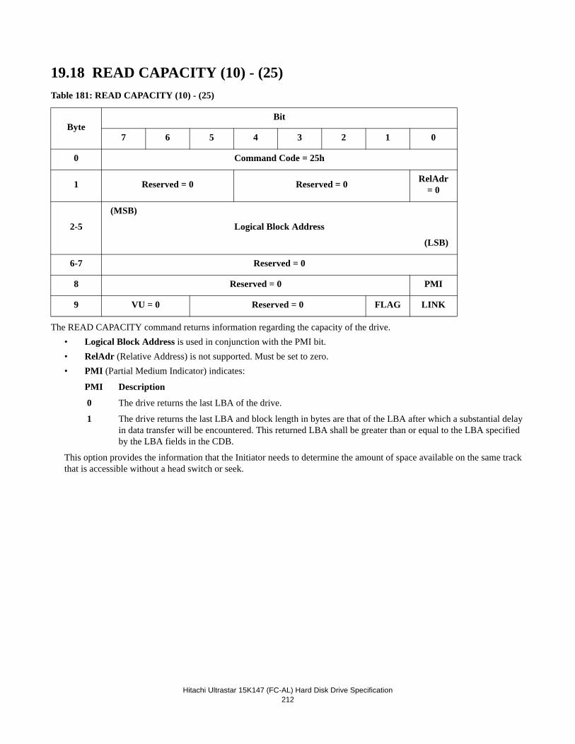
Hitachi Ultrastar 15K147 (FC-AL) Hard Disk Drive Specification212
19.18 READ CAPACITY (10) - (25)Table 181: READ CAPACITY (10) - (25)
The READ CAPACITY command returns information regarding the capacity of the drive.• Logical Block Address is used in conjunction with the PMI bit.• RelAdr (Relative Address) is not supported. Must be set to zero.• PMI (Partial Medium Indicator) indicates:
PMI Description
0 The drive returns the last LBA of the drive.
1 The drive returns the last LBA and block length in bytes are that of the LBA after which a substantial delay in data transfer will be encountered. This returned LBA shall be greater than or equal to the LBA specified by the LBA fields in the CDB.
This option provides the information that the Initiator needs to determine the amount of space available on the same track that is accessible without a head switch or seek.
ByteBit
7 6 5 4 3 2 1 0
0 Command Code = 25h
1 Reserved = 0 Reserved = 0 RelAdr = 0
2-5
(MSB)
Logical Block Address
(LSB)
6-7 Reserved = 0
8 Reserved = 0 PMI
9 VU = 0 Reserved = 0 FLAG LINK
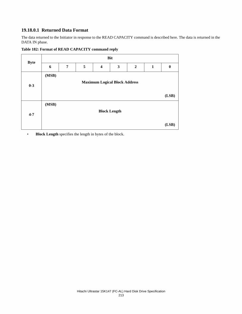
Hitachi Ultrastar 15K147 (FC-AL) Hard Disk Drive Specification213
19.18.0.1 Returned Data FormatThe data returned to the Initiator in response to the READ CAPACITY command is described here. The data is returned in the DATA IN phase.
Table 182: Format of READ CAPACITY command reply
• Block Length specifies the length in bytes of the block.
ByteBit
6 7 5 4 3 2 1 0
0-3
(MSB)
Maximum Logical Block Address
(LSB)
4-7
(MSB)
Block Length
(LSB)
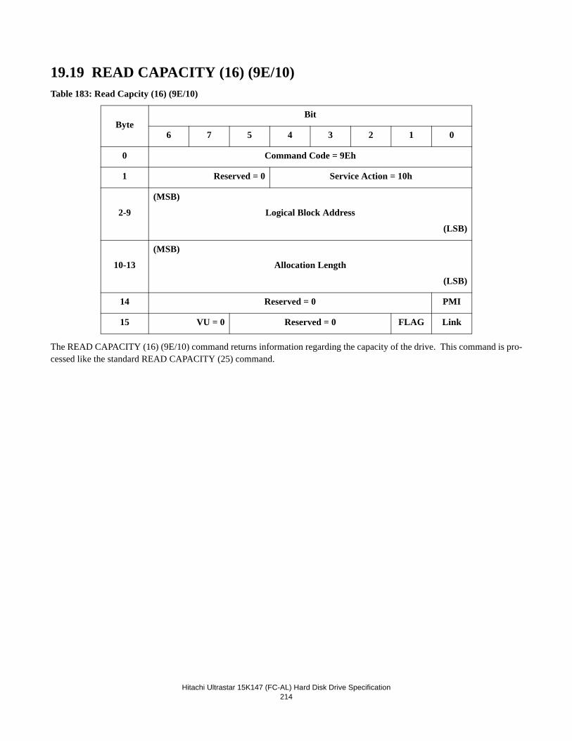
Hitachi Ultrastar 15K147 (FC-AL) Hard Disk Drive Specification214
19.19 READ CAPACITY (16) (9E/10)Table 183: Read Capcity (16) (9E/10)
The READ CAPACITY (16) (9E/10) command returns information regarding the capacity of the drive. This command is pro-cessed like the standard READ CAPACITY (25) command.
ByteBit
6 7 5 4 3 2 1 0
0 Command Code = 9Eh
1 Reserved = 0 Service Action = 10h
2-9
(MSB)
Logical Block Address
(LSB)
10-13
(MSB)
Allocation Length
(LSB)
14 Reserved = 0 PMI
15 VU = 0 Reserved = 0 FLAG Link
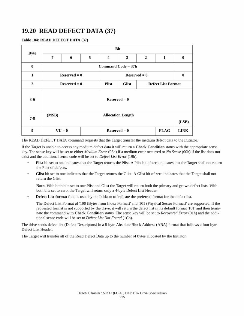
Hitachi Ultrastar 15K147 (FC-AL) Hard Disk Drive Specification215
19.20 READ DEFECT DATA (37)Table 184: READ DEFECT DATA (37)
The READ DEFECT DATA command requests that the Target transfer the medium defect data to the Initiator.
If the Target is unable to access any medium defect data it will return a Check Condition status with the appropriate sense key. The sense key will be set to either Medium Error (03h) if a medium error occurred or No Sense (00h) if the list does not exist and the additional sense code will be set to Defect List Error (19h).
• Plist bit set to one indicates that the Target returns the Plist. A Plist bit of zero indicates that the Target shall not return the Plist of defects.
• Glist bit set to one indicates that the Target returns the Glist. A Glist bit of zero indicates that the Target shall not return the Glist.
Note: With both bits set to one Plist and Glist the Target will return both the primary and grown defect lists. With both bits set to zero, the Target will return only a 4-byte Defect List Header.
• Defect List format field is used by the Initiator to indicate the preferred format for the defect list.
The Defect List Format of '100 (Bytes from Index Format)' and '101 (Physical Sector Format)' are supported. If the requested format is not supported by the drive, it will return the defect list in its default format '101' and then termi-nate the command with Check Condition status. The sense key will be set to Recovered Error (01h) and the addi-tional sense code will be set to Defect List Not Found (1Ch).
The drive sends defect list (Defect Descriptors) in a 8-byte Absolute Block Address (ABA) format that follows a four byte Defect List Header.
The Target will transfer all of the Read Defect Data up to the number of bytes allocated by the Initiator.
ByteBit
7 6 5 4 3 2 1 0
0 Command Code = 37h
1 Reserved = 0 Reserved = 0 0
2 Reserved = 0 Plist Glist Defect List Format
3-6 Reserved = 0
7-8(MSB) Allocation Length
(LSB)
9 VU = 0 Reserved = 0 FLAG LINK
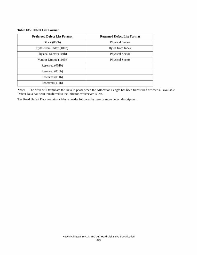
Hitachi Ultrastar 15K147 (FC-AL) Hard Disk Drive Specification216
Table 185: Defect List Format
Note: The drive will terminate the Data In phase when the Allocation Length has been transferred or when all available Defect Data has been transferred to the Initiator, whichever is less.
The Read Defect Data contains a 4-byte header followed by zero or more defect descriptors.
Preferred Defect List Format Returned Defect List Format
Block (000b) Physical Sector
Bytes from Index (100b) Bytes from Index
Physical Sector (101b) Physical Sector
Vendor Unique (110b) Physical Sector
Reserved (001b)
Reserved (010b)
Reserved (011b)
Reserved (111b)
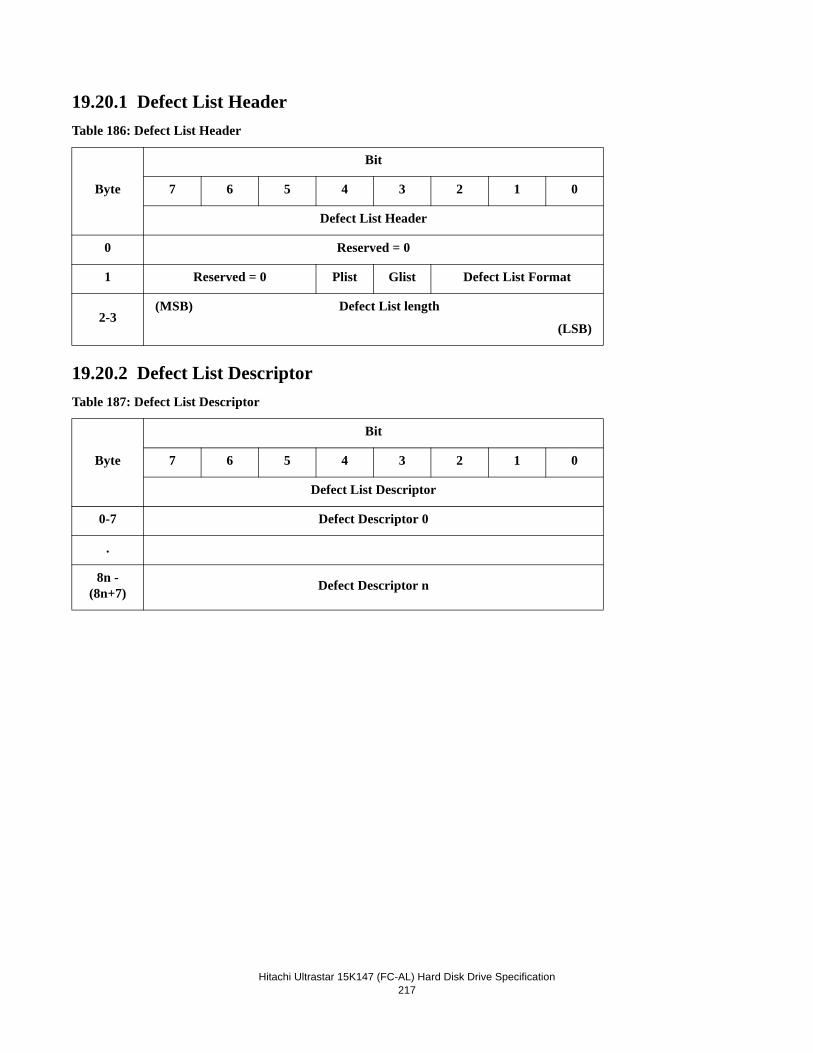
Hitachi Ultrastar 15K147 (FC-AL) Hard Disk Drive Specification217
19.20.1 Defect List HeaderTable 186: Defect List Header
19.20.2 Defect List DescriptorTable 187: Defect List Descriptor
Byte
Bit
7 6 5 4 3 2 1 0
Defect List Header
0 Reserved = 0
1 Reserved = 0 Plist Glist Defect List Format
2-3(MSB) Defect List length
(LSB)
Byte
Bit
7 6 5 4 3 2 1 0
Defect List Descriptor
0-7 Defect Descriptor 0
.
8n - (8n+7) Defect Descriptor n
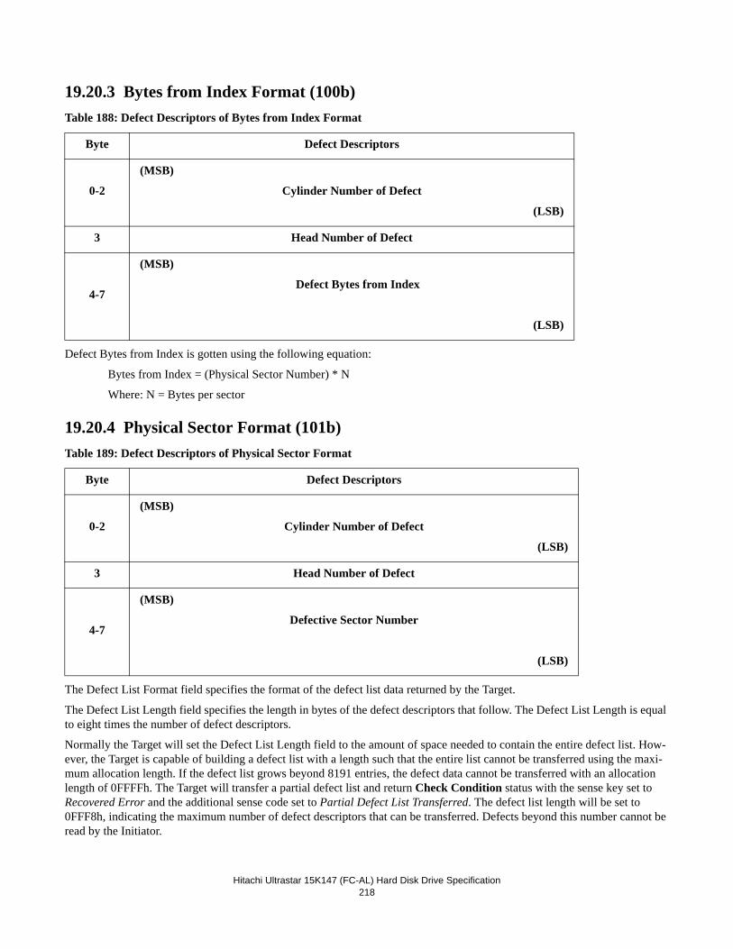
Hitachi Ultrastar 15K147 (FC-AL) Hard Disk Drive Specification218
19.20.3 Bytes from Index Format (100b)Table 188: Defect Descriptors of Bytes from Index Format
Defect Bytes from Index is gotten using the following equation:
Bytes from Index = (Physical Sector Number) * N
Where: N = Bytes per sector
19.20.4 Physical Sector Format (101b)Table 189: Defect Descriptors of Physical Sector Format
The Defect List Format field specifies the format of the defect list data returned by the Target.
The Defect List Length field specifies the length in bytes of the defect descriptors that follow. The Defect List Length is equal to eight times the number of defect descriptors.
Normally the Target will set the Defect List Length field to the amount of space needed to contain the entire defect list. How-ever, the Target is capable of building a defect list with a length such that the entire list cannot be transferred using the maxi-mum allocation length. If the defect list grows beyond 8191 entries, the defect data cannot be transferred with an allocation length of 0FFFFh. The Target will transfer a partial defect list and return Check Condition status with the sense key set to Recovered Error and the additional sense code set to Partial Defect List Transferred. The defect list length will be set to 0FFF8h, indicating the maximum number of defect descriptors that can be transferred. Defects beyond this number cannot be read by the Initiator.
Byte Defect Descriptors
0-2
(MSB)
Cylinder Number of Defect
(LSB)
3 Head Number of Defect
4-7
(MSB)
Defect Bytes from Index
(LSB)
Byte Defect Descriptors
0-2
(MSB)
Cylinder Number of Defect
(LSB)
3 Head Number of Defect
4-7
(MSB)
Defective Sector Number
(LSB)
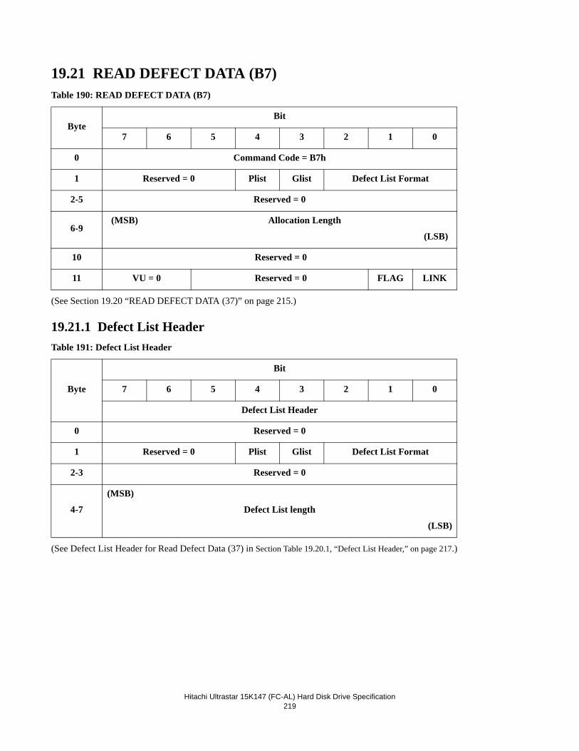
Hitachi Ultrastar 15K147 (FC-AL) Hard Disk Drive Specification219
19.21 READ DEFECT DATA (B7)Table 190: READ DEFECT DATA (B7)
(See Section 19.20 “READ DEFECT DATA (37)” on page 215.)
19.21.1 Defect List HeaderTable 191: Defect List Header
(See Defect List Header for Read Defect Data (37) in Section Table 19.20.1, “Defect List Header,” on page 217.)
ByteBit
7 6 5 4 3 2 1 0
0 Command Code = B7h
1 Reserved = 0 Plist Glist Defect List Format
2-5 Reserved = 0
6-9(MSB) Allocation Length
(LSB)
10 Reserved = 0
11 VU = 0 Reserved = 0 FLAG LINK
Byte
Bit
7 6 5 4 3 2 1 0
Defect List Header
0 Reserved = 0
1 Reserved = 0 Plist Glist Defect List Format
2-3 Reserved = 0
4-7
(MSB)
Defect List length
(LSB)
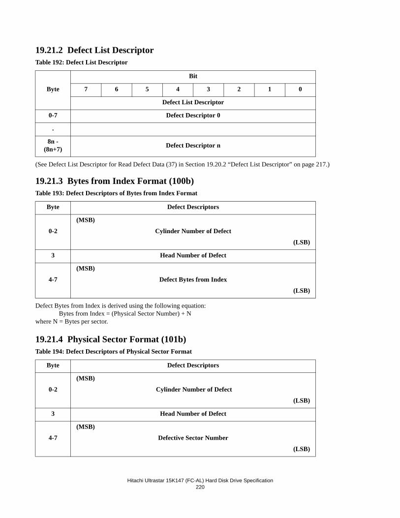
Hitachi Ultrastar 15K147 (FC-AL) Hard Disk Drive Specification220
19.21.2 Defect List DescriptorTable 192: Defect List Descriptor
(See Defect List Descriptor for Read Defect Data (37) in Section 19.20.2 “Defect List Descriptor” on page 217.)
19.21.3 Bytes from Index Format (100b)Table 193: Defect Descriptors of Bytes from Index Format
Defect Bytes from Index is derived using the following equation:Bytes from Index = (Physical Sector Number) + N
where N = Bytes per sector.
19.21.4 Physical Sector Format (101b)Table 194: Defect Descriptors of Physical Sector Format
Byte
Bit
7 6 5 4 3 2 1 0
Defect List Descriptor
0-7 Defect Descriptor 0
.
8n - (8n+7) Defect Descriptor n
Byte Defect Descriptors
0-2
(MSB)
Cylinder Number of Defect
(LSB)
3 Head Number of Defect
4-7
(MSB)
Defect Bytes from Index
(LSB)
Byte Defect Descriptors
0-2
(MSB)
Cylinder Number of Defect
(LSB)
3 Head Number of Defect
4-7
(MSB)
Defective Sector Number
(LSB)
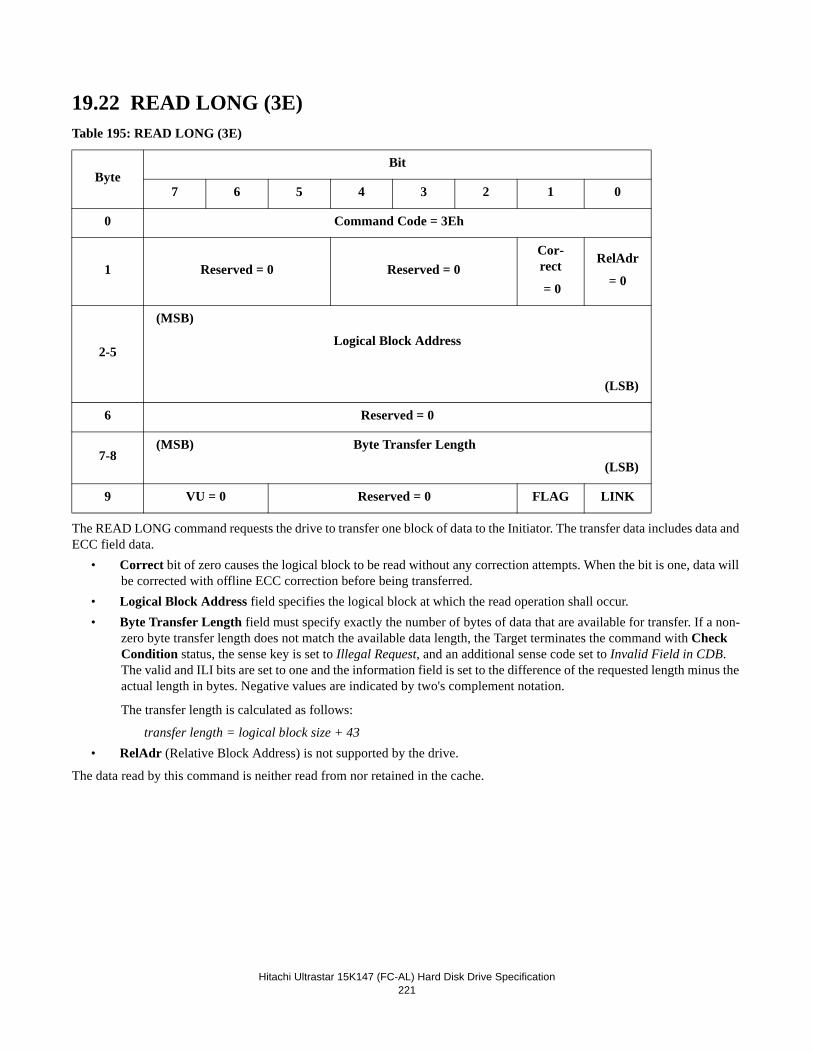
Hitachi Ultrastar 15K147 (FC-AL) Hard Disk Drive Specification221
19.22 READ LONG (3E)Table 195: READ LONG (3E)
The READ LONG command requests the drive to transfer one block of data to the Initiator. The transfer data includes data and ECC field data.
• Correct bit of zero causes the logical block to be read without any correction attempts. When the bit is one, data will be corrected with offline ECC correction before being transferred.
• Logical Block Address field specifies the logical block at which the read operation shall occur.• Byte Transfer Length field must specify exactly the number of bytes of data that are available for transfer. If a non-
zero byte transfer length does not match the available data length, the Target terminates the command with Check Condition status, the sense key is set to Illegal Request, and an additional sense code set to Invalid Field in CDB. The valid and ILI bits are set to one and the information field is set to the difference of the requested length minus the actual length in bytes. Negative values are indicated by two's complement notation.
The transfer length is calculated as follows:
transfer length = logical block size + 43• RelAdr (Relative Block Address) is not supported by the drive.
The data read by this command is neither read from nor retained in the cache.
ByteBit
7 6 5 4 3 2 1 0
0 Command Code = 3Eh
1 Reserved = 0 Reserved = 0Cor-rect
= 0
RelAdr
= 0
2-5
(MSB)
Logical Block Address
(LSB)
6 Reserved = 0
7-8(MSB) Byte Transfer Length
(LSB)
9 VU = 0 Reserved = 0 FLAG LINK
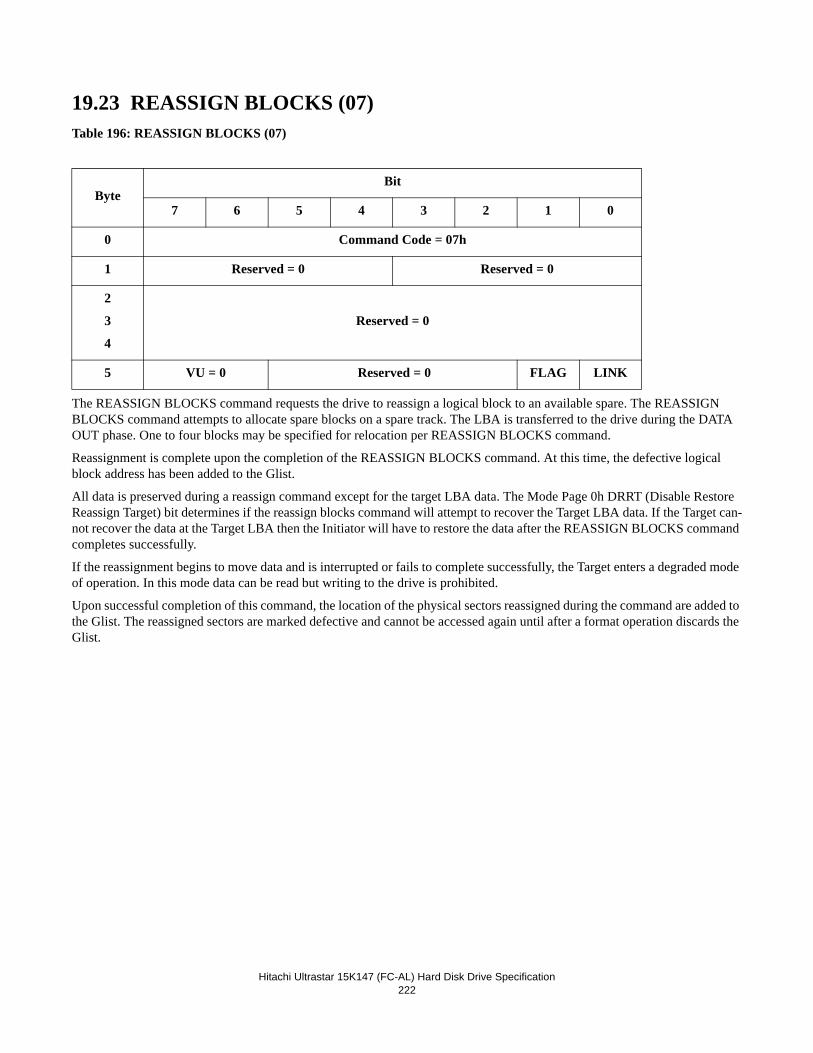
Hitachi Ultrastar 15K147 (FC-AL) Hard Disk Drive Specification222
19.23 REASSIGN BLOCKS (07)Table 196: REASSIGN BLOCKS (07)
The REASSIGN BLOCKS command requests the drive to reassign a logical block to an available spare. The REASSIGN BLOCKS command attempts to allocate spare blocks on a spare track. The LBA is transferred to the drive during the DATA OUT phase. One to four blocks may be specified for relocation per REASSIGN BLOCKS command.
Reassignment is complete upon the completion of the REASSIGN BLOCKS command. At this time, the defective logical block address has been added to the Glist.
All data is preserved during a reassign command except for the target LBA data. The Mode Page 0h DRRT (Disable Restore Reassign Target) bit determines if the reassign blocks command will attempt to recover the Target LBA data. If the Target can-not recover the data at the Target LBA then the Initiator will have to restore the data after the REASSIGN BLOCKS command completes successfully.
If the reassignment begins to move data and is interrupted or fails to complete successfully, the Target enters a degraded mode of operation. In this mode data can be read but writing to the drive is prohibited.
Upon successful completion of this command, the location of the physical sectors reassigned during the command are added to the Glist. The reassigned sectors are marked defective and cannot be accessed again until after a format operation discards the Glist.
ByteBit
7 6 5 4 3 2 1 0
0 Command Code = 07h
1 Reserved = 0 Reserved = 0
2
3
4
Reserved = 0
5 VU = 0 Reserved = 0 FLAG LINK
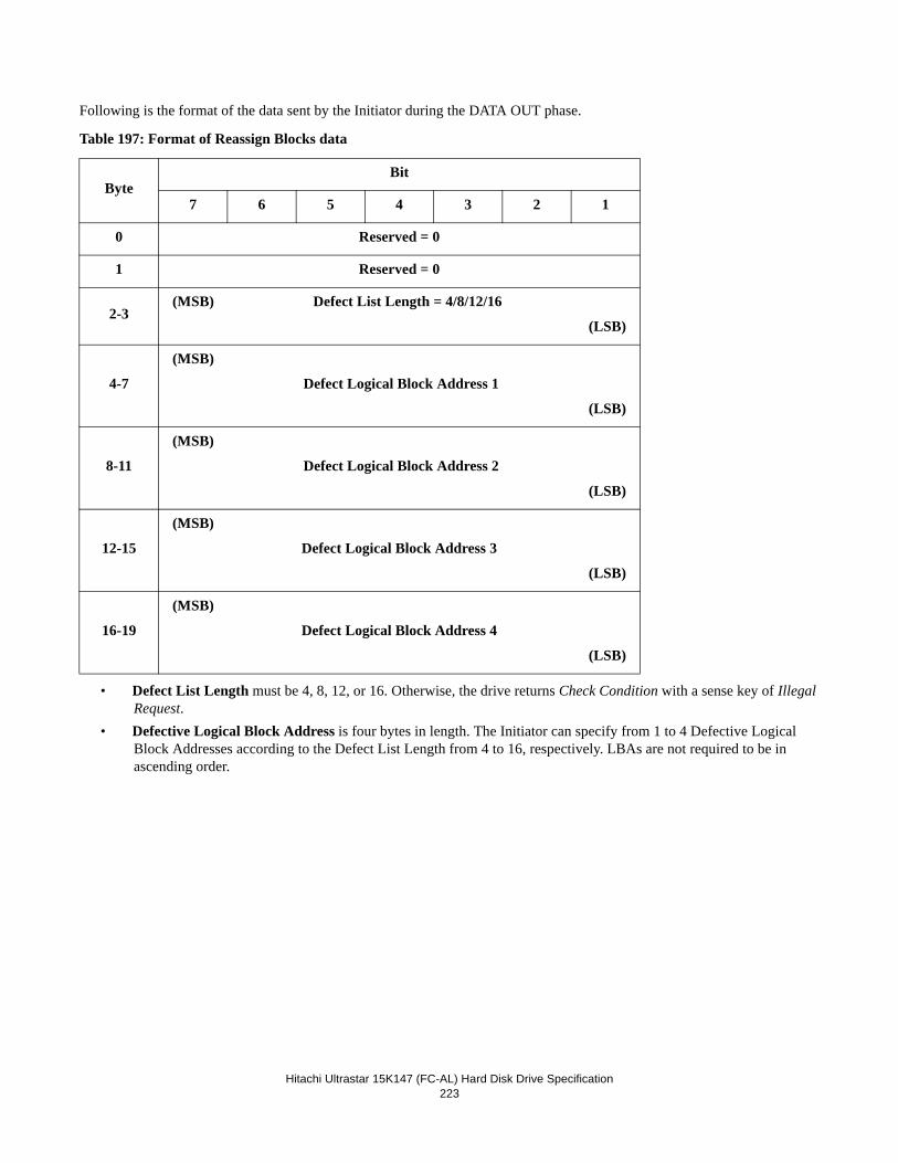
Hitachi Ultrastar 15K147 (FC-AL) Hard Disk Drive Specification223
Following is the format of the data sent by the Initiator during the DATA OUT phase.
Table 197: Format of Reassign Blocks data
• Defect List Length must be 4, 8, 12, or 16. Otherwise, the drive returns Check Condition with a sense key of Illegal Request.
• Defective Logical Block Address is four bytes in length. The Initiator can specify from 1 to 4 Defective Logical Block Addresses according to the Defect List Length from 4 to 16, respectively. LBAs are not required to be in ascending order.
ByteBit
7 6 5 4 3 2 1
0 Reserved = 0
1 Reserved = 0
2-3(MSB) Defect List Length = 4/8/12/16
(LSB)
4-7
(MSB)
Defect Logical Block Address 1
(LSB)
8-11
(MSB)
Defect Logical Block Address 2
(LSB)
12-15
(MSB)
Defect Logical Block Address 3
(LSB)
16-19
(MSB)
Defect Logical Block Address 4
(LSB)
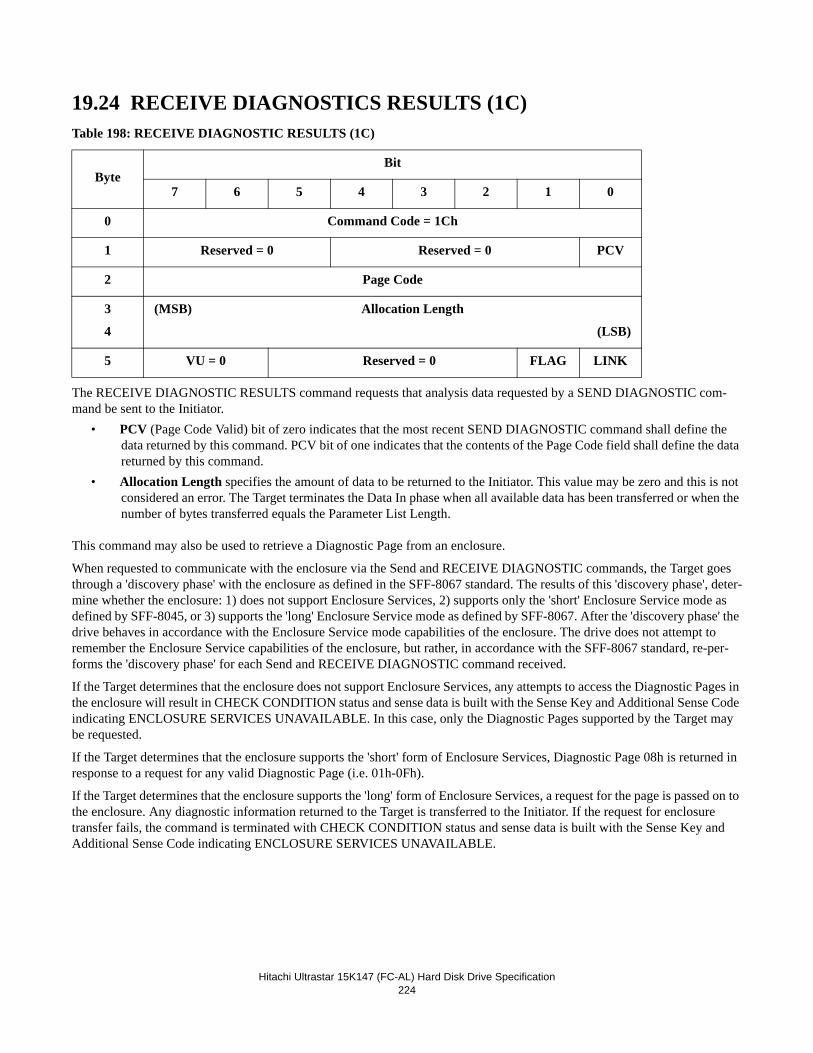
Hitachi Ultrastar 15K147 (FC-AL) Hard Disk Drive Specification224
19.24 RECEIVE DIAGNOSTICS RESULTS (1C)Table 198: RECEIVE DIAGNOSTIC RESULTS (1C)
The RECEIVE DIAGNOSTIC RESULTS command requests that analysis data requested by a SEND DIAGNOSTIC com-mand be sent to the Initiator.
• PCV (Page Code Valid) bit of zero indicates that the most recent SEND DIAGNOSTIC command shall define the data returned by this command. PCV bit of one indicates that the contents of the Page Code field shall define the data returned by this command.
• Allocation Length specifies the amount of data to be returned to the Initiator. This value may be zero and this is not considered an error. The Target terminates the Data In phase when all available data has been transferred or when the number of bytes transferred equals the Parameter List Length.
This command may also be used to retrieve a Diagnostic Page from an enclosure.
When requested to communicate with the enclosure via the Send and RECEIVE DIAGNOSTIC commands, the Target goes through a 'discovery phase' with the enclosure as defined in the SFF-8067 standard. The results of this 'discovery phase', deter-mine whether the enclosure: 1) does not support Enclosure Services, 2) supports only the 'short' Enclosure Service mode as defined by SFF-8045, or 3) supports the 'long' Enclosure Service mode as defined by SFF-8067. After the 'discovery phase' the drive behaves in accordance with the Enclosure Service mode capabilities of the enclosure. The drive does not attempt to remember the Enclosure Service capabilities of the enclosure, but rather, in accordance with the SFF-8067 standard, re-per-forms the 'discovery phase' for each Send and RECEIVE DIAGNOSTIC command received.
If the Target determines that the enclosure does not support Enclosure Services, any attempts to access the Diagnostic Pages in the enclosure will result in CHECK CONDITION status and sense data is built with the Sense Key and Additional Sense Code indicating ENCLOSURE SERVICES UNAVAILABLE. In this case, only the Diagnostic Pages supported by the Target may be requested.
If the Target determines that the enclosure supports the 'short' form of Enclosure Services, Diagnostic Page 08h is returned in response to a request for any valid Diagnostic Page (i.e. 01h-0Fh).
If the Target determines that the enclosure supports the 'long' form of Enclosure Services, a request for the page is passed on to the enclosure. Any diagnostic information returned to the Target is transferred to the Initiator. If the request for enclosure transfer fails, the command is terminated with CHECK CONDITION status and sense data is built with the Sense Key and Additional Sense Code indicating ENCLOSURE SERVICES UNAVAILABLE.
ByteBit
7 6 5 4 3 2 1 0
0 Command Code = 1Ch
1 Reserved = 0 Reserved = 0 PCV
2 Page Code
3
4
(MSB) Allocation Length
(LSB)
5 VU = 0 Reserved = 0 FLAG LINK
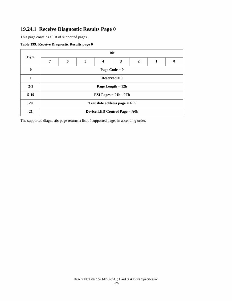
Hitachi Ultrastar 15K147 (FC-AL) Hard Disk Drive Specification225
19.24.1 Receive Diagnostic Results Page 0This page contains a list of supported pages.
Table 199: Receive Diagnostic Results page 0
The supported diagnostic page returns a list of supported pages in ascending order.
ByteBit
7 6 5 4 3 2 1 0
0 Page Code = 0
1 Reserved = 0
2-3 Page Length = 12h
5-19 ESI Pages = 01h - 0Fh
20 Translate address page = 40h
21 Device LED Control Page = A0h
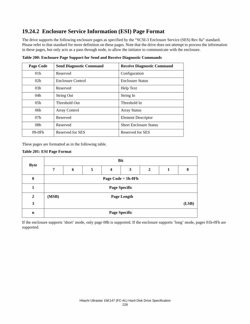
Hitachi Ultrastar 15K147 (FC-AL) Hard Disk Drive Specification226
19.24.2 Enclosure Service Information (ESI) Page FormatThe drive supports the following enclosure pages as specified by the “SCSI-3 Enclosure Service (SES) Rev 8a” standard. Please refer to that standard for more definition on these pages. Note that the drive does not attempt to process the information in these pages, but only acts as a pass through node, to allow the initiator to communicate with the enclosure.
Table 200: Enclosure Page Support for Send and Receive Diagnostic Commands
These pages are formatted as in the following table.
Table 201: ESI Page Format
If the enclosure supports ’short’ mode, only page 08h is supported. If the enclosure supports ’long’ mode, pages 01h-0Fh are supported.
Page Code Send Diagnostic Command Receive Diagnostic Command
01h Reserved Configuration
02h Enclosure Control Enclosure Status
03h Reserved Help Text
04h String Out String In
05h Threshold Out Threshold In
06h Array Control Array Status
07h Reserved Element Descriptor
08h Reserved Short Enclosure Status
09-0Fh Reserved for SES Reserved for SES
ByteBit
7 6 5 4 3 2 1 0
0 Page Code = 1h-0Fh
1 Page Specific
2
3
(MSB) Page Length
(LSB)
n Page Specific
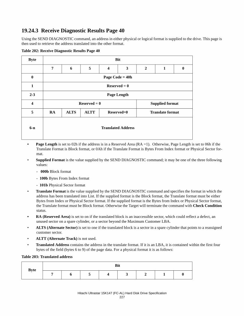
Hitachi Ultrastar 15K147 (FC-AL) Hard Disk Drive Specification227
19.24.3 Receive Diagnostic Results Page 40Using the SEND DIAGNOSTIC command, an address in either physical or logical format is supplied to the drive. This page is then used to retrieve the address translated into the other format.
Table 202: Receive Diagnostic Results Page 40
• Page Length is set to 02h if the address is in a Reserved Area (RA =1). Otherwise, Page Length is set to 06h if the Translate Format is Block format, or 0Ah if the Translate Format is Bytes From Index format or Physical Sector for-mat.
• Supplied Format is the value supplied by the SEND DIAGNOSTIC command; it may be one of the three following values:
- 000b Block format
- 100b Bytes From Index format
- 101b Physical Sector format• Translate Format is the value supplied by the SEND DIAGNOSTIC command and specifies the format in which the
address has been translated into List. If the supplied format is the Block format, the Translate format must be either Bytes from Index or Physical Sector format. If the supplied format is the Bytes from Index or Physical Sector format, the Translate format must be Block format. Otherwise the Target will terminate the command with Check Condition status.
• RA (Reserved Area) is set to on if the translated block is an inaccessible sector, which could reflect a defect, an unused sector on a spare cylinder, or a sector beyond the Maximum Customer LBA.
• ALTS (Alternate Sector) is set to one if the translated block is a sector in a spare cylinder that points to a reassigned customer sector.
• ALTT (Alternate Track) is not used. • Translated Address contains the address in the translate format. If it is an LBA, it is contained within the first four
bytes of the field (bytes 6 to 9) of the page data. For a physical format it is as follows:
Table 203: Translated address
Byte Bit
7 6 5 4 3 2 1 0
0 Page Code = 40h
1 Reserved = 0
2-3 Page Length
4 Reserved = 0 Supplied format
5 RA ALTS ALTT Reserved=0 Translate format
6-n Translated Address
ByteBit
7 6 5 4 3 2 1 0
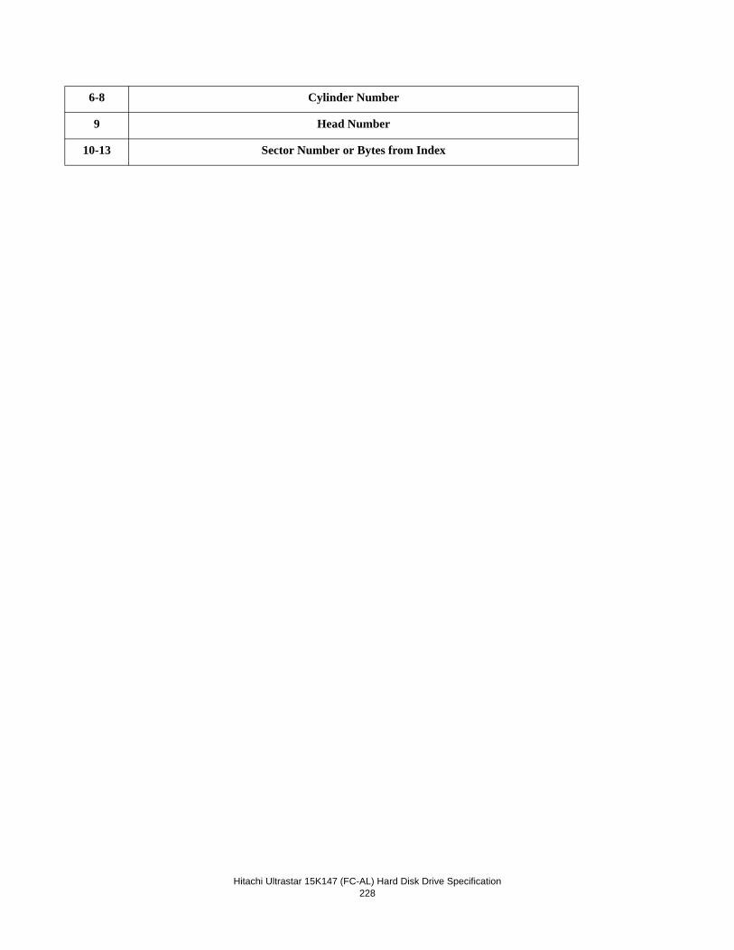
Hitachi Ultrastar 15K147 (FC-AL) Hard Disk Drive Specification228
6-8 Cylinder Number
9 Head Number
10-13 Sector Number or Bytes from Index
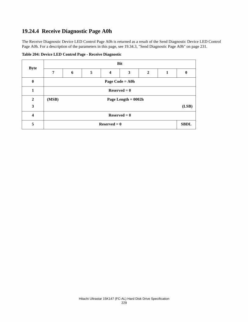
Hitachi Ultrastar 15K147 (FC-AL) Hard Disk Drive Specification229
19.24.4 Receive Diagnostic Page A0h
The Receive Diagnostic Device LED Control Page A0h is returned as a result of the Send Diagnostic Device LED Control Page A0h. For a description of the parameters in this page, see 19.34.3, "Send Diagnostic Page A0h" on page 231.
Table 204: Device LED Control Page - Receive Diagnostic
ByteBit
7 6 5 4 3 2 1 0
0 Page Code = A0h
1 Reserved = 0
2
3
(MSB) Page Length = 0002h
(LSB)
4 Reserved = 0
5 Reserved = 0 SBDL
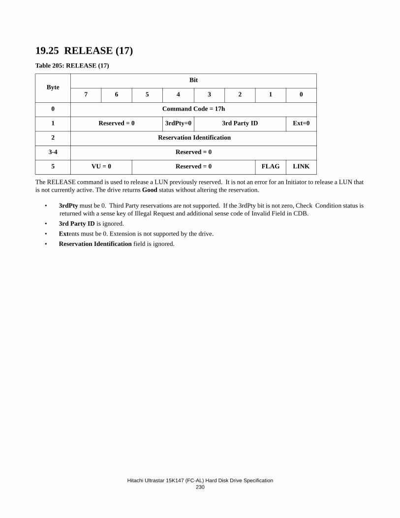
Hitachi Ultrastar 15K147 (FC-AL) Hard Disk Drive Specification230
19.25 RELEASE (17)Table 205: RELEASE (17)
The RELEASE command is used to release a LUN previously reserved. It is not an error for an Initiator to release a LUN that is not currently active. The drive returns Good status without altering the reservation.
• 3rdPty must be 0. Third Party reservations are not supported. If the 3rdPty bit is not zero, Check Condition status is returned with a sense key of Illegal Request and additional sense code of Invalid Field in CDB.
• 3rd Party ID is ignored.• Extents must be 0. Extension is not supported by the drive.• Reservation Identification field is ignored.
ByteBit
7 6 5 4 3 2 1 0
0 Command Code = 17h
1 Reserved = 0 3rdPty=0 3rd Party ID Ext=0
2 Reservation Identification
3-4 Reserved = 0
5 VU = 0 Reserved = 0 FLAG LINK
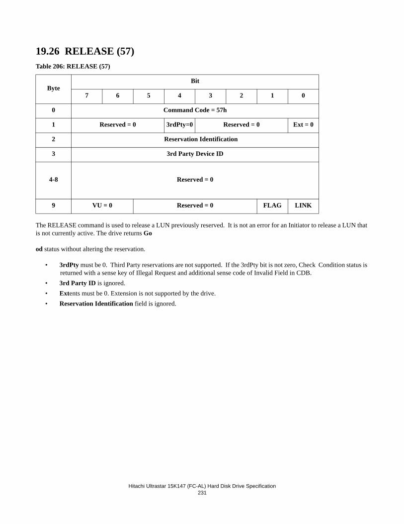
Hitachi Ultrastar 15K147 (FC-AL) Hard Disk Drive Specification231
19.26 RELEASE (57)Table 206: RELEASE (57)
The RELEASE command is used to release a LUN previously reserved. It is not an error for an Initiator to release a LUN that is not currently active. The drive returns Go
od status without altering the reservation.
• 3rdPty must be 0. Third Party reservations are not supported. If the 3rdPty bit is not zero, Check Condition status is returned with a sense key of Illegal Request and additional sense code of Invalid Field in CDB.
• 3rd Party ID is ignored.• Extents must be 0. Extension is not supported by the drive.• Reservation Identification field is ignored.
ByteBit
7 6 5 4 3 2 1 0
0 Command Code = 57h
1 Reserved = 0 3rdPty=0 Reserved = 0 Ext = 0
2 Reservation Identification
3 3rd Party Device ID
4-8 Reserved = 0
9 VU = 0 Reserved = 0 FLAG LINK
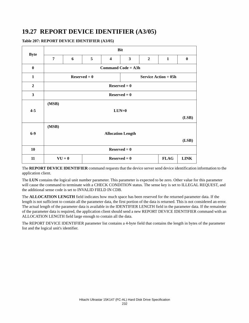
Hitachi Ultrastar 15K147 (FC-AL) Hard Disk Drive Specification232
19.27 REPORT DEVICE IDENTIFIER (A3/05)Table 207: REPORT DEVICE IDENTIFIER (A3/05)
The REPORT DEVICE IDENTIFIER command requests that the device server send device identification information to the application client.
The LUN contains the logical unit number parameter. This parameter is expected to be zero. Other value for this parameter will cause the command to terminate with a CHECK CONDITION status. The sense key is set to ILLEGAL REQUEST, and the additional sense code is set to INVALID FIELD IN CDB.
The ALLOCATION LENGTH field indicates how much space has been reserved for the returned parameter data. If the length is not sufficient to contain all the parameter data, the first portion of the data is returned. This is not considered an error. The actual length of the parameter data is available in the IDENTIFIER LENGTH field in the parameter data. If the remainder of the parameter data is required, the application client should send a new REPORT DEVICE IDENTIFIER command with an ALLOCATION LENGTH field large enough to contain all the data.
The REPORT DEVICE IDENTIFIER parameter list contains a 4-byte field that contains the length in bytes of the parameter list and the logical unit's identifier.
ByteBit
7 6 5 4 3 2 1 0
0 Command Code = A3h
1 Reserved = 0 Service Action = 05h
2 Reserved = 0
3 Reserved = 0
4-5
(MSB)
LUN=0
(LSB)
6-9
(MSB)
Allocation Length
(LSB)
10 Reserved = 0
11 VU = 0 Reserved = 0 FLAG LINK
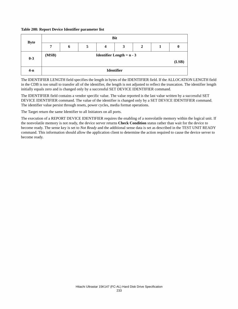
Hitachi Ultrastar 15K147 (FC-AL) Hard Disk Drive Specification233
Table 208: Report Device Identifier parameter list
The IDENTIFIER LENGTH field specifies the length in bytes of the IDENTIFIER field. If the ALLOCATION LENGTH field in the CDB is too small to transfer all of the identifier, the length is not adjusted to reflect the truncation. The identifier length initially equals zero and is changed only by a successful SET DEVICE IDENTIFIER command.
The IDENTIFIER field contains a vendor specific value. The value reported is the last value written by a successful SET DEVICE IDENTIFIER command. The value of the identifier is changed only by a SET DEVICE IDENTIFIER command. The identifier value persist through resets, power cycles, media format operations.
The Target return the same Identifier to all Initiators on all ports.
The execution of a REPORT DEVICE IDENTIFIER requires the enabling of a nonvolatile memory within the logical unit. If the nonvolatile memory is not ready, the device server returns Check Condition status rather than wait for the device to become ready. The sense key is set to Not Ready and the additional sense data is set as described in the TEST UNIT READY command. This information should allow the application client to determine the action required to cause the device server to become ready.
ByteBit
7 6 5 4 3 2 1 0
0-3(MSB) Identifier Length = n - 3
(LSB)
4-n Identifier
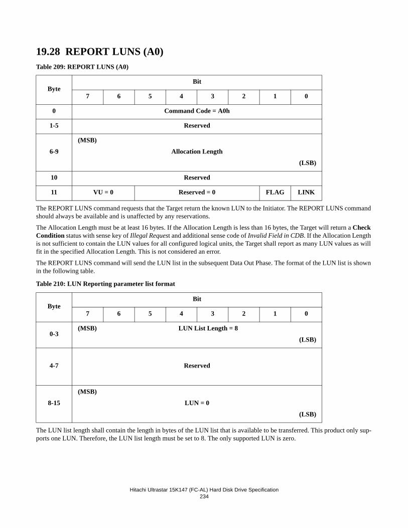
Hitachi Ultrastar 15K147 (FC-AL) Hard Disk Drive Specification234
19.28 REPORT LUNS (A0)Table 209: REPORT LUNS (A0)
The REPORT LUNS command requests that the Target return the known LUN to the Initiator. The REPORT LUNS command should always be available and is unaffected by any reservations.
The Allocation Length must be at least 16 bytes. If the Allocation Length is less than 16 bytes, the Target will return a Check Condition status with sense key of Illegal Request and additional sense code of Invalid Field in CDB. If the Allocation Length is not sufficient to contain the LUN values for all configured logical units, the Target shall report as many LUN values as will fit in the specified Allocation Length. This is not considered an error.
The REPORT LUNS command will send the LUN list in the subsequent Data Out Phase. The format of the LUN list is shown in the following table.
Table 210: LUN Reporting parameter list format
The LUN list length shall contain the length in bytes of the LUN list that is available to be transferred. This product only sup-ports one LUN. Therefore, the LUN list length must be set to 8. The only supported LUN is zero.
ByteBit
7 6 5 4 3 2 1 0
0 Command Code = A0h
1-5 Reserved
6-9
(MSB)
Allocation Length
(LSB)
10 Reserved
11 VU = 0 Reserved = 0 FLAG LINK
ByteBit
7 6 5 4 3 2 1 0
0-3(MSB) LUN List Length = 8
(LSB)
4-7 Reserved
8-15
(MSB)
LUN = 0
(LSB)
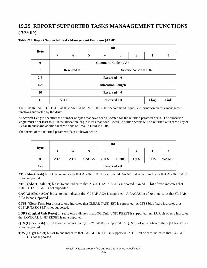
Hitachi Ultrastar 15K147 (FC-AL) Hard Disk Drive Specification235
19.29 REPORT SUPPORTED TASKS MANAAGEMENT FUNCTIONS (A3/0D)Table 211: Report Supported Tasks Management Functions (A3/0D)
The REPORT SUPPORTED TASK MANAGEMENT FUNCTIONS command requests information on task management functions supported by the drive.
Allocation Length specifies the number of bytes that have been allocated for the returned parameter data. The allocation length must be at least four. If the allocation length is less than four, Check Condition Status will be returned with sense key of Illegal Request and additional sense code of Invalid Field in CDB.
The format of the returned parameter data is shown below.
ATS (Abort Task) bit set to one indicates that ABORT TASK is supported. An ATS bit of zero indicates that ABORT TASK is not supported.
ATSS (Abort Task Set) bit set to one indicates that ABORT TASK SET is supported. An ATSS bit of zero indicates that ABORT TASK SET is not supported.
CACAS (Clear ACA) bit set to one indicates that CLEAR ACA is supported. A CACAS bit of zero indicates that CLEAR ACA is not supported.
CTSS (Clear Task Set) bit set to one indicates that CLEAR TASK SET is supported. A CTSS bit of zero indicates that CLEAR TASK SET is not supported.
LURS (Logical Unit Reset) bit set to one indicates that LOGICAL UNIT RESET is supported. An LUR bit of zero indicates that LOGICAL UNIT RESET is not supported.
QTS (Query Task) bit set to one indicates that QUERY TASK is supported. A QTS bit of zero indicates that QUERY TASK is not supported.
TRS (Target Reset) bit set to one indicates that TARGET RESET is supported. A TRS bit of zero indicates that TARGET RESET is not supported.
ByteBit
7 6 5 4 3 2 1 0
0 Command Code = A3h
1 Reserved = 0 Service Action = 0Dh
2-5 Reserved = 0
6-9 Allocation Length
10 Reserved = 0
11 VU = 0 Reserved = 0 Flag Link
ByteBit
7 6 5 4 3 2 1 0
0 ATS ATSS CACAS CTSS LURS QTS TRS WAKES
1-3 Reserved = 0
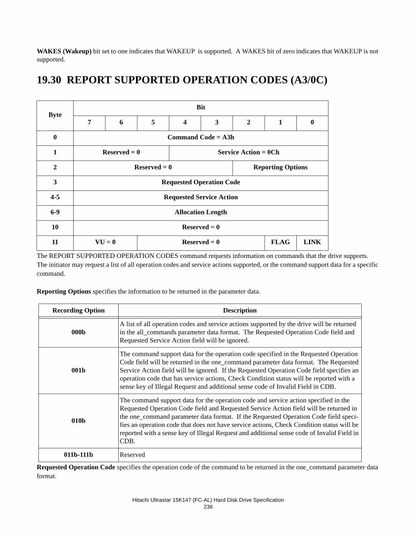
Hitachi Ultrastar 15K147 (FC-AL) Hard Disk Drive Specification236
WAKES (Wakeup) bit set to one indicates that WAKEUP is supported. A WAKES bit of zero indicates that WAKEUP is not supported.
19.30 REPORT SUPPORTED OPERATION CODES (A3/0C)
The REPORT SUPPORTED OPERATION CODES command requests information on commands that the drive supports. The initiator may request a list of all operation codes and service actions supported, or the command support data for a specific command.
Reporting Options specifies the information to be returned in the parameter data.
Requested Operation Code specifies the operation code of the command to be returned in the one_command parameter data format.
ByteBit
7 6 5 4 3 2 1 0
0 Command Code = A3h
1 Reserved = 0 Service Action = 0Ch
2 Reserved = 0 Reporting Options
3 Requested Operation Code
4-5 Requested Service Action
6-9 Allocation Length
10 Reserved = 0
11 VU = 0 Reserved = 0 FLAG LINK
Recording Option Description
000bA list of all operation codes and service actions supported by the drive will be returned in the all_commands parameter data format. The Requested Operation Code field and Requested Service Action field will be ignored.
001b
The command support data for the operation code specified in the Requested Operation Code field will be returned in the one_command parameter data format. The Requested Service Action field will be ignored. If the Requested Operation Code field specifies an operation code that has service actions, Check Condition status will be reported with a sense key of Illegal Request and additional sense code of Invalid Field in CDB.
010b
The command support data for the operation code and service action specified in the Requested Operation Code field and Requested Service Action field will be returned in the one_command parameter data format. If the Requested Operation Code field speci-fies an operation code that does not have service actions, Check Condition status will be reported with a sense key of Illegal Request and additional sense code of Invalid Field in CDB.
011b-111b Reserved
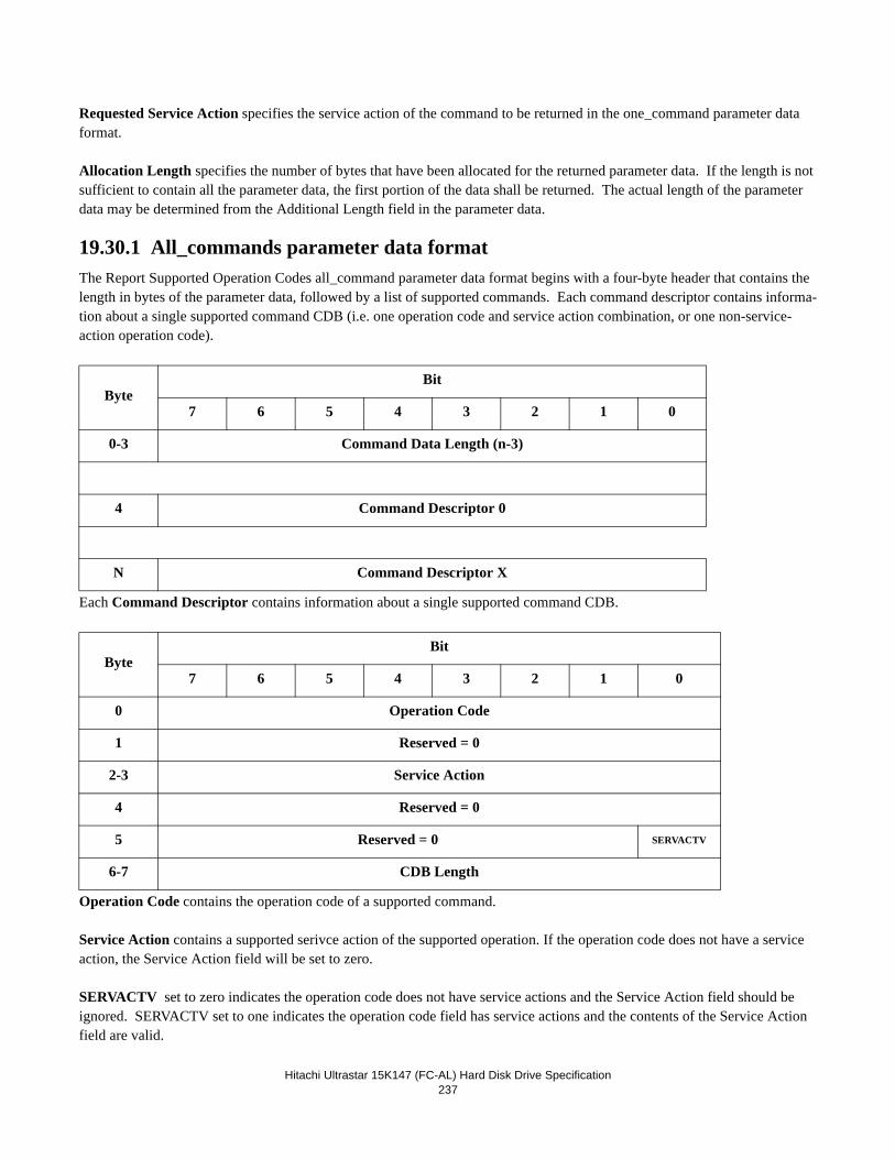
Hitachi Ultrastar 15K147 (FC-AL) Hard Disk Drive Specification237
Requested Service Action specifies the service action of the command to be returned in the one_command parameter data format.
Allocation Length specifies the number of bytes that have been allocated for the returned parameter data. If the length is not sufficient to contain all the parameter data, the first portion of the data shall be returned. The actual length of the parameter data may be determined from the Additional Length field in the parameter data.
19.30.1 All_commands parameter data formatThe Report Supported Operation Codes all_command parameter data format begins with a four-byte header that contains the length in bytes of the parameter data, followed by a list of supported commands. Each command descriptor contains informa-tion about a single supported command CDB (i.e. one operation code and service action combination, or one non-service-action operation code).
Each Command Descriptor contains information about a single supported command CDB.
Operation Code contains the operation code of a supported command.
Service Action contains a supported serivce action of the supported operation. If the operation code does not have a service action, the Service Action field will be set to zero.
SERVACTV set to zero indicates the operation code does not have service actions and the Service Action field should be ignored. SERVACTV set to one indicates the operation code field has service actions and the contents of the Service Action field are valid.
ByteBit
7 6 5 4 3 2 1 0
0-3 Command Data Length (n-3)
4 Command Descriptor 0
N Command Descriptor X
ByteBit
7 6 5 4 3 2 1 0
0 Operation Code
1 Reserved = 0
2-3 Service Action
4 Reserved = 0
5 Reserved = 0 SERVACTV
6-7 CDB Length
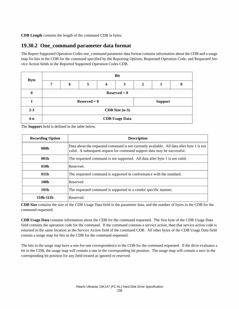
Hitachi Ultrastar 15K147 (FC-AL) Hard Disk Drive Specification238
CDB Length contains the length of the command CDB in bytes.
19.30.2 One_command parameter data formatThe Report Supported Operation Codes one_command parameter data format contains information about the CDB and a usage map for bits in the CDB for the command specified by the Reporting Options, Requested Operation Code, and Requested Ser-vice Action fields in the Reported Supported Operation Codes CDB.
The Support field is defined in the table below.
CDB Size contains the size of the CDB Usage Data field in the parameter data, and the number of bytes in the CDB for the command requested.
CDB Usage Data contains information about the CDB for the command requested. The first byte of the CDB Usage Data field contains the operation code for the command. If the command contains a service action, then that service action code is returned in the same location as the Service Action field of the command CDB. All other bytes of the CDB Usage Data field contain a usage map for bits in the CDB for the command requested.
The bits in the usage map have a one-for-one correspondence to the CDB for the command requested. If the drive evaluates a bit in the CDB, the usage map will contain a one in the corresponding bit position. The usage map will contain a zero in the corresponding bit position for any field treated as ignored or reserved.
ByteBit
7 6 5 4 3 2 1 0
0 Reserved = 0
1 Reserved = 0 Support
2-3 CDB Size (n-3)
4-n CDB Usage Data
Recording Option Description
000b Data about the requested command is not currently available. All data after byte 1 is not valid. A subsequent request for command support data may be successful.
001b The requested command is not supported. All data after byte 1 is not valid.
010b Reserved.
011b The requested command is supported in conformance with the standard.
100b Reserved
101b The requested command is supported in a vendor specific manner.
110b-111b Reserved.
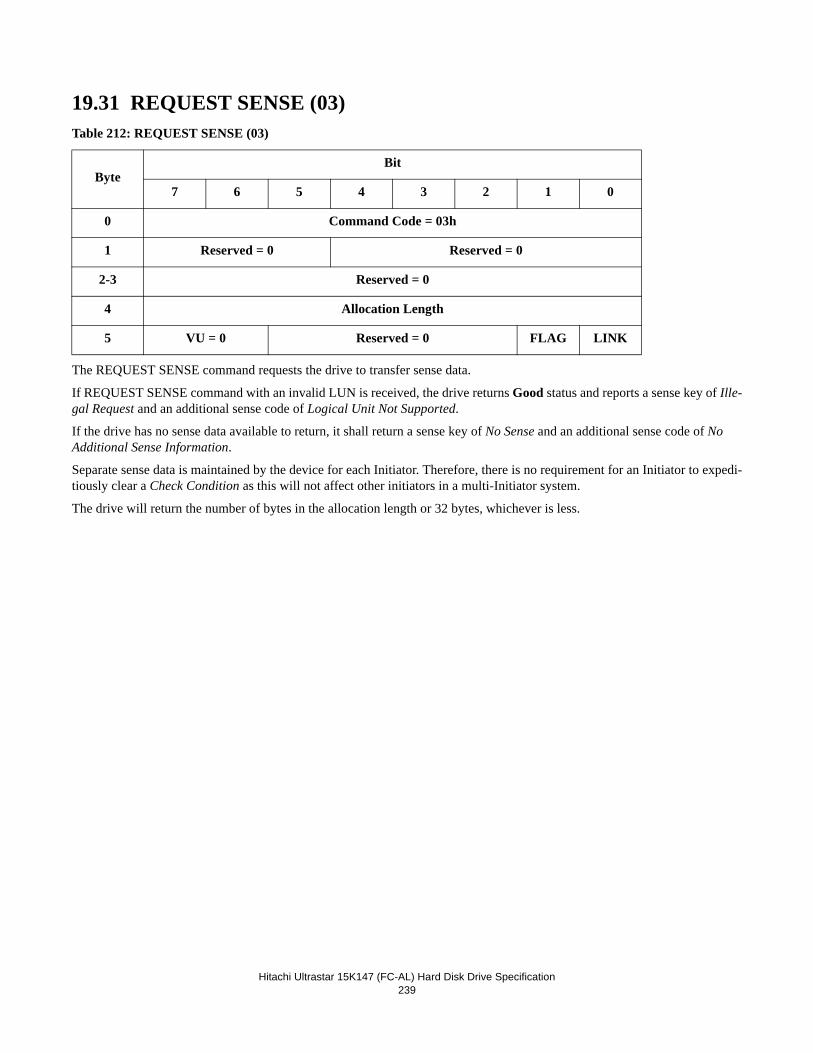
Hitachi Ultrastar 15K147 (FC-AL) Hard Disk Drive Specification239
19.31 REQUEST SENSE (03)Table 212: REQUEST SENSE (03)
The REQUEST SENSE command requests the drive to transfer sense data.
If REQUEST SENSE command with an invalid LUN is received, the drive returns Good status and reports a sense key of Ille-gal Request and an additional sense code of Logical Unit Not Supported.
If the drive has no sense data available to return, it shall return a sense key of No Sense and an additional sense code of No Additional Sense Information.
Separate sense data is maintained by the device for each Initiator. Therefore, there is no requirement for an Initiator to expedi-tiously clear a Check Condition as this will not affect other initiators in a multi-Initiator system.
The drive will return the number of bytes in the allocation length or 32 bytes, whichever is less.
ByteBit
7 6 5 4 3 2 1 0
0 Command Code = 03h
1 Reserved = 0 Reserved = 0
2-3 Reserved = 0
4 Allocation Length
5 VU = 0 Reserved = 0 FLAG LINK
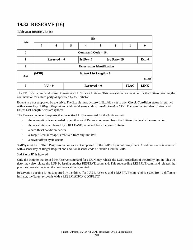
Hitachi Ultrastar 15K147 (FC-AL) Hard Disk Drive Specification240
19.32 RESERVE (16)Table 213: RESERVE (16)
The RESERVE command is used to reserve a LUN for an Initiator. This reservation can be either for the Initiator sending the command or for a third party as specified by the Initiator.
Extents are not supported by the drive. The Ext bit must be zero. If Ext bit is set to one, Check Condition status is returned with a sense key of Illegal Request and additional sense code of Invalid Field in CDB. The Reservation Identification and Extent List Length fields are ignored.
The Reserve command requests that the entire LUN be reserved for the Initiator until• the reservation is superseded by another valid Reserve command from the Initiator that made the reservation.• the reservation is released by a RELEASE command from the same Initiator.• a hard Reset condition occurs.• a Target Reset message is received from any Initiator.• a power off/on cycle occurs.
3rdPty must be 0. Third Party reservations are not supported. If the 3rdPty bit is not zero, Check Condition status is returned with a sense key of Illegal Request and additional sense code of Invalid Field in CDB.
3rd Party ID is ignored.
Only the Initiator that issued the Reserve command for a LUN may release the LUN, regardless of the 3rdPty option. This Ini-tiator may also release the LUN by issuing another RESERVE command. This superseding RESERVE command releases the previous reservation when the new reservation is granted.
Reservation queuing is not supported by the drive. If a LUN is reserved and a RESERVE command is issued from a different Initiator, the Target responds with a RESERVATION CONFLICT.
ByteBit
7 6 5 4 3 2 1 0
0 Command Code = 16h
1 Reserved = 0 3rdPty=0 3rd Party ID Ext=0
2 Reservation Identification
3-4(MSB) Extent List Length = 0
(LSB)
5 VU = 0 Reserved = 0 FLAG LINK
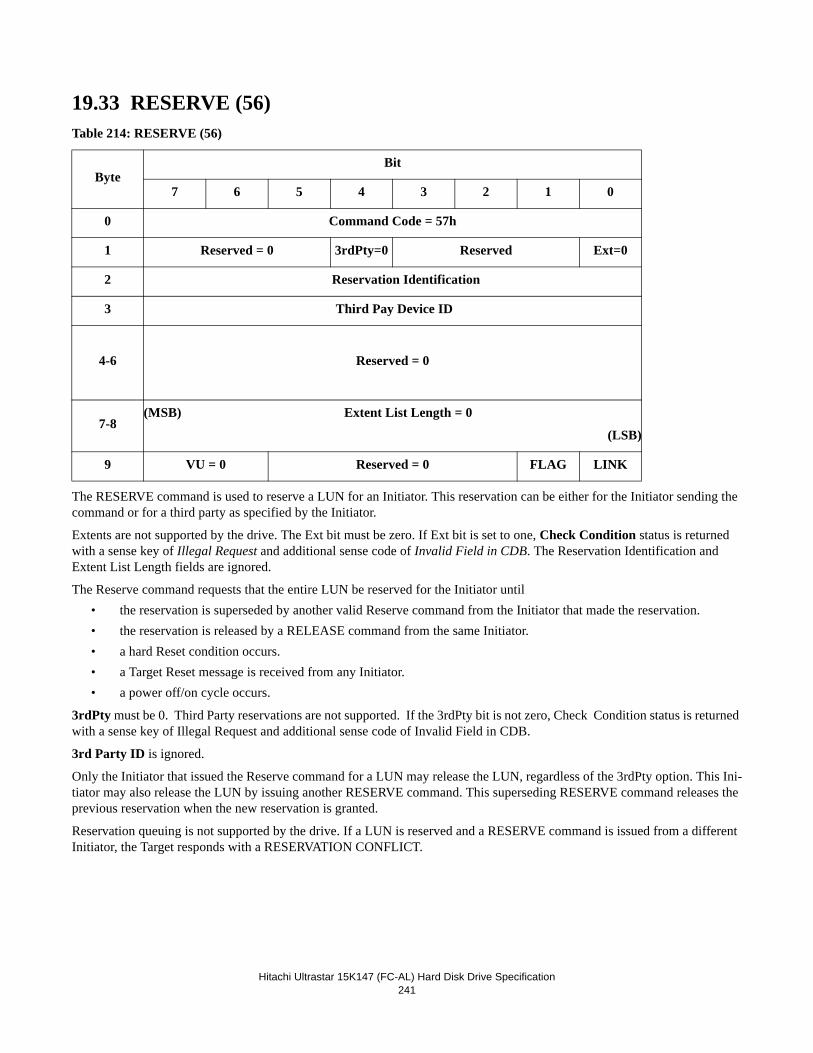
Hitachi Ultrastar 15K147 (FC-AL) Hard Disk Drive Specification241
19.33 RESERVE (56)Table 214: RESERVE (56)
The RESERVE command is used to reserve a LUN for an Initiator. This reservation can be either for the Initiator sending the command or for a third party as specified by the Initiator.
Extents are not supported by the drive. The Ext bit must be zero. If Ext bit is set to one, Check Condition status is returned with a sense key of Illegal Request and additional sense code of Invalid Field in CDB. The Reservation Identification and Extent List Length fields are ignored.
The Reserve command requests that the entire LUN be reserved for the Initiator until• the reservation is superseded by another valid Reserve command from the Initiator that made the reservation.• the reservation is released by a RELEASE command from the same Initiator.• a hard Reset condition occurs.• a Target Reset message is received from any Initiator.• a power off/on cycle occurs.
3rdPty must be 0. Third Party reservations are not supported. If the 3rdPty bit is not zero, Check Condition status is returned with a sense key of Illegal Request and additional sense code of Invalid Field in CDB.
3rd Party ID is ignored.
Only the Initiator that issued the Reserve command for a LUN may release the LUN, regardless of the 3rdPty option. This Ini-tiator may also release the LUN by issuing another RESERVE command. This superseding RESERVE command releases the previous reservation when the new reservation is granted.
Reservation queuing is not supported by the drive. If a LUN is reserved and a RESERVE command is issued from a different Initiator, the Target responds with a RESERVATION CONFLICT.
ByteBit
7 6 5 4 3 2 1 0
0 Command Code = 57h
1 Reserved = 0 3rdPty=0 Reserved Ext=0
2 Reservation Identification
3 Third Pay Device ID
4-6 Reserved = 0
7-8(MSB) Extent List Length = 0
(LSB)
9 VU = 0 Reserved = 0 FLAG LINK
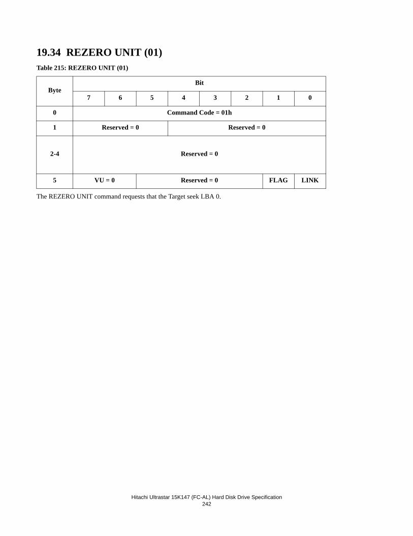
Hitachi Ultrastar 15K147 (FC-AL) Hard Disk Drive Specification242
19.34 REZERO UNIT (01)Table 215: REZERO UNIT (01)
The REZERO UNIT command requests that the Target seek LBA 0.
ByteBit
7 6 5 4 3 2 1 0
0 Command Code = 01h
1 Reserved = 0 Reserved = 0
2-4 Reserved = 0
5 VU = 0 Reserved = 0 FLAG LINK
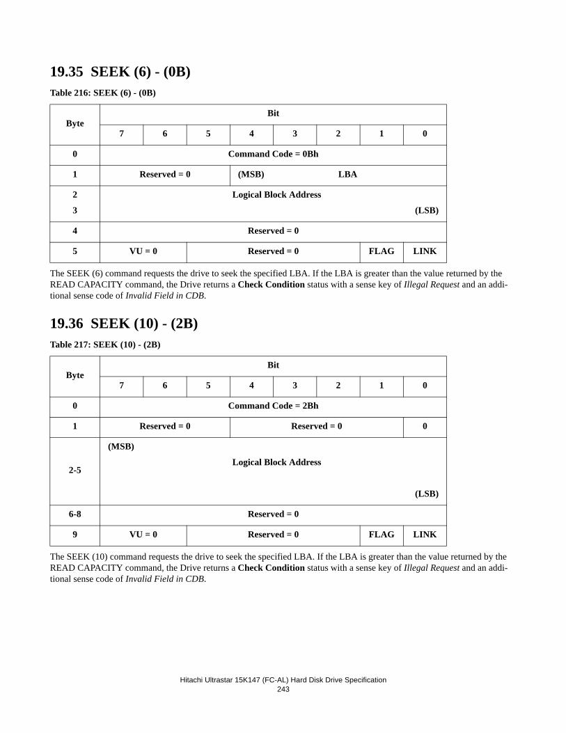
Hitachi Ultrastar 15K147 (FC-AL) Hard Disk Drive Specification243
19.35 SEEK (6) - (0B)Table 216: SEEK (6) - (0B)
The SEEK (6) command requests the drive to seek the specified LBA. If the LBA is greater than the value returned by the READ CAPACITY command, the Drive returns a Check Condition status with a sense key of Illegal Request and an addi-tional sense code of Invalid Field in CDB.
19.36 SEEK (10) - (2B)Table 217: SEEK (10) - (2B)
The SEEK (10) command requests the drive to seek the specified LBA. If the LBA is greater than the value returned by the READ CAPACITY command, the Drive returns a Check Condition status with a sense key of Illegal Request and an addi-tional sense code of Invalid Field in CDB.
ByteBit
7 6 5 4 3 2 1 0
0 Command Code = 0Bh
1 Reserved = 0 (MSB) LBA
2
3
Logical Block Address
(LSB)
4 Reserved = 0
5 VU = 0 Reserved = 0 FLAG LINK
ByteBit
7 6 5 4 3 2 1 0
0 Command Code = 2Bh
1 Reserved = 0 Reserved = 0 0
2-5
(MSB)
Logical Block Address
(LSB)
6-8 Reserved = 0
9 VU = 0 Reserved = 0 FLAG LINK
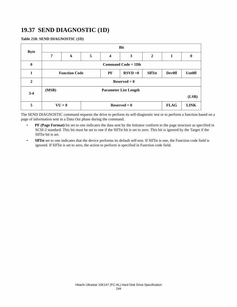
Hitachi Ultrastar 15K147 (FC-AL) Hard Disk Drive Specification244
19.37 SEND DIAGNOSTIC (1D)Table 218: SEND DIAGNOSTIC (1D)
The SEND DIAGNOSTIC command requests the drive to perform its self-diagnostic test or to perform a function based on a page of information sent in a Data Out phase during the command.
• PF (Page Format) bit set to one indicates the data sent by the Initiator conform to the page structure as specified in SCSI-2 standard. This bit must be set to one if the SlfTst bit is set to zero. This bit is ignored by the Target if the SlfTst bit is set.
• SlfTst set to one indicates that the device performs its default self-test. If SlfTst is one, the Function code field is ignored. If SlfTst is set to zero, the action to perform is specified in Function code field.
ByteBit
7 6 5 4 3 2 1 0
0 Command Code = 1Dh
1 Function Code PF RSVD =0 SlfTst Dev0fl Unt0fl
2 Reserved = 0
3-4(MSB) Parameter List Length
(LSB)
5 VU = 0 Reserved = 0 FLAG LINK
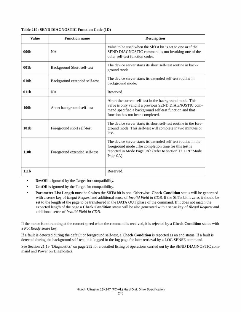
Hitachi Ultrastar 15K147 (FC-AL) Hard Disk Drive Specification245
Table 219: SEND DIAGNOSTIC Function Code (1D)
• DevOfl is ignored by the Target for compatibility.• UntOfl is ignored by the Target for compatibility.• Parameter List Length must be 0 when the SlfTst bit is one. Otherwise, Check Condition status will be generated
with a sense key of Illegal Request and additional sense of Invalid Field in CDB. If the SlfTst bit is zero, it should be set to the length of the page to be transferred in the DATA OUT phase of the command. If it does not match the expected length of the page a Check Condition status will be also generated with a sense key of Illegal Request and additional sense of Invalid Field in CDB.
If the motor is not running at the correct speed when the command is received, it is rejected by a Check Condition status with a Not Ready sense key.
If a fault is detected during the default or foreground self-test, a Check Condition is reported as an end status. If a fault is detected during the background self-test, it is logged in the log page for later retrieval by a LOG SENSE command.
See Section 21.19 "Diagnostics" on page 292 for a detailed listing of operations carried out by the SEND DIAGNOSTIC com-mand and Power on Diagnostics.
Value Function name Description
000b NAValue to be used when the SlfTst bit is set to one or if the SEND DIAGNOSTIC command is not invoking one of the other self-test function codes.
001b Background Short self-test The device server starts its short self-test routine in back-ground mode.
010b Background extended self-test The device server starts its extended self-test routine in background mode.
011b NA Reserved.
100b Abort background self-test
Abort the current self-test in the background mode. This value is only valid if a previous SEND DIAGNOSTIC com-mand specified a background self-test function and that function has not been completed.
101b Foreground short self-testThe device server starts its short self-test routine in the fore-ground mode. This self-test will complete in two minutes or less.
110b Foreground extended self-test
The device server starts its extended self-test routine in the foreground mode .The completion time for this test is reported in Mode Page 0Ah (refer to section 17.11.9 "Mode Page 0A).
111b Reserved.
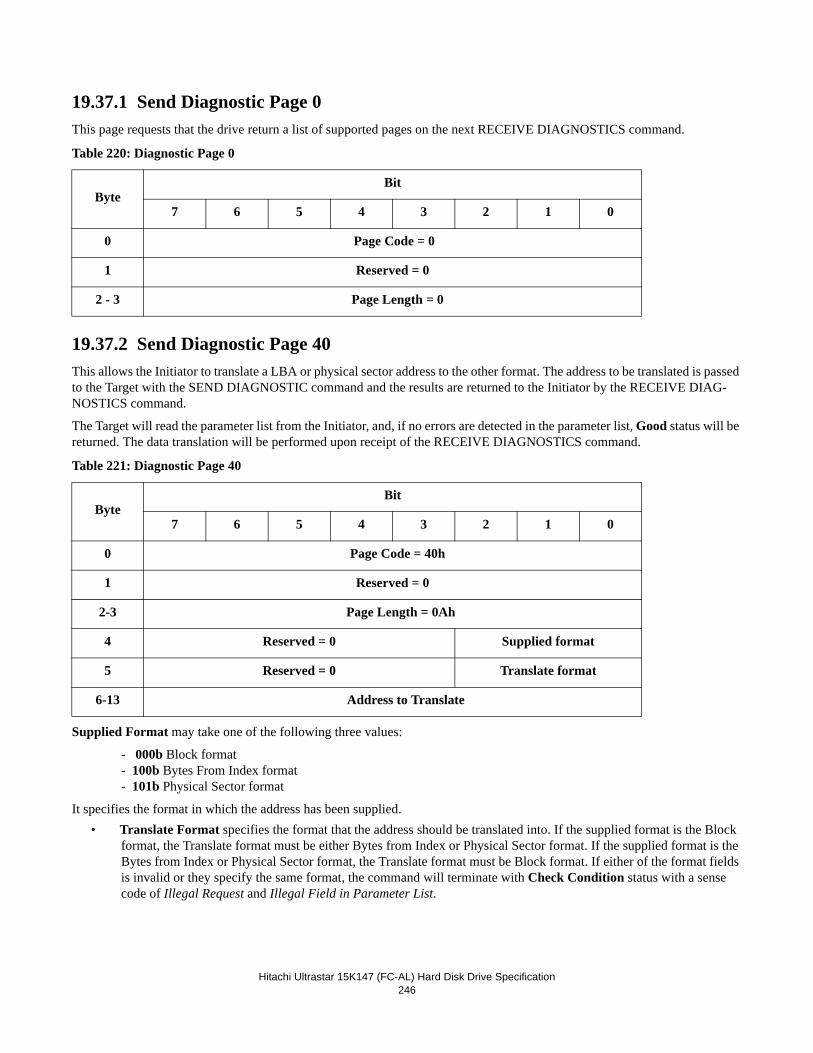
Hitachi Ultrastar 15K147 (FC-AL) Hard Disk Drive Specification246
19.37.1 Send Diagnostic Page 0This page requests that the drive return a list of supported pages on the next RECEIVE DIAGNOSTICS command.
Table 220: Diagnostic Page 0
19.37.2 Send Diagnostic Page 40This allows the Initiator to translate a LBA or physical sector address to the other format. The address to be translated is passed to the Target with the SEND DIAGNOSTIC command and the results are returned to the Initiator by the RECEIVE DIAG-NOSTICS command.
The Target will read the parameter list from the Initiator, and, if no errors are detected in the parameter list, Good status will be returned. The data translation will be performed upon receipt of the RECEIVE DIAGNOSTICS command.
Table 221: Diagnostic Page 40
Supplied Format may take one of the following three values:
- 000b Block format- 100b Bytes From Index format- 101b Physical Sector format
It specifies the format in which the address has been supplied.• Translate Format specifies the format that the address should be translated into. If the supplied format is the Block
format, the Translate format must be either Bytes from Index or Physical Sector format. If the supplied format is the Bytes from Index or Physical Sector format, the Translate format must be Block format. If either of the format fields is invalid or they specify the same format, the command will terminate with Check Condition status with a sense code of Illegal Request and Illegal Field in Parameter List.
ByteBit
7 6 5 4 3 2 1 0
0 Page Code = 0
1 Reserved = 0
2 - 3 Page Length = 0
ByteBit
7 6 5 4 3 2 1 0
0 Page Code = 40h
1 Reserved = 0
2-3 Page Length = 0Ah
4 Reserved = 0 Supplied format
5 Reserved = 0 Translate format
6-13 Address to Translate
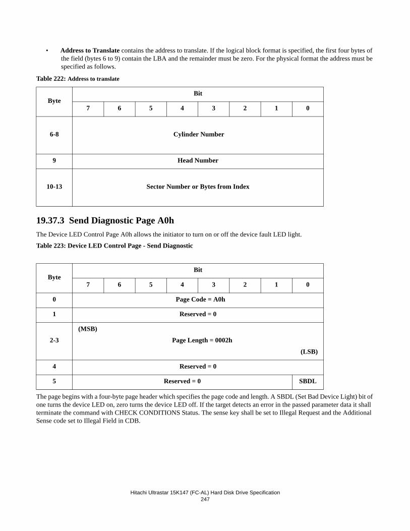
Hitachi Ultrastar 15K147 (FC-AL) Hard Disk Drive Specification247
• Address to Translate contains the address to translate. If the logical block format is specified, the first four bytes of the field (bytes 6 to 9) contain the LBA and the remainder must be zero. For the physical format the address must be specified as follows.
Table 222: Address to translate
19.37.3 Send Diagnostic Page A0hThe Device LED Control Page A0h allows the initiator to turn on or off the device fault LED light.
Table 223: Device LED Control Page - Send Diagnostic
The page begins with a four-byte page header which specifies the page code and length. A SBDL (Set Bad Device Light) bit of one turns the device LED on, zero turns the device LED off. If the target detects an error in the passed parameter data it shall terminate the command with CHECK CONDITIONS Status. The sense key shall be set to Illegal Request and the Additional Sense code set to Illegal Field in CDB.
ByteBit
7 6 5 4 3 2 1 0
6-8
Cylinder Number
9 Head Number
10-13 Sector Number or Bytes from Index
ByteBit
7 6 5 4 3 2 1 0
0 Page Code = A0h
1 Reserved = 0
2-3
(MSB)
Page Length = 0002h
(LSB)
4 Reserved = 0
5 Reserved = 0 SBDL
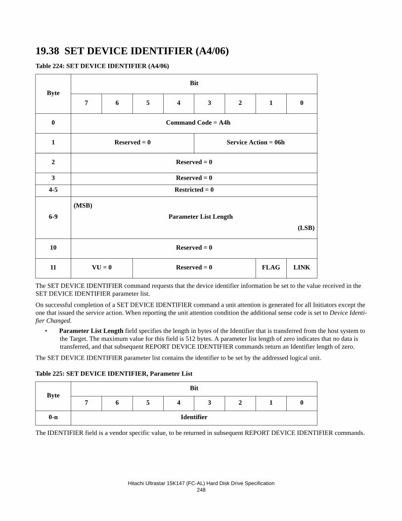
Hitachi Ultrastar 15K147 (FC-AL) Hard Disk Drive Specification248
19.38 SET DEVICE IDENTIFIER (A4/06)Table 224: SET DEVICE IDENTIFIER (A4/06)
The SET DEVICE IDENTIFIER command requests that the device identifier information be set to the value received in the SET DEVICE IDENTIFIER parameter list.
On successful completion of a SET DEVICE IDENTIFIER command a unit attention is generated for all Initiators except the one that issued the service action. When reporting the unit attention condition the additional sense code is set to Device Identi-fier Changed.
• Parameter List Length field specifies the length in bytes of the Identifier that is transferred from the host system to the Target. The maximum value for this field is 512 bytes. A parameter list length of zero indicates that no data is transferred, and that subsequent REPORT DEVICE IDENTIFIER commands return an Identifier length of zero.
The SET DEVICE IDENTIFIER parameter list contains the identifier to be set by the addressed logical unit.
Table 225: SET DEVICE IDENTIFIER, Parameter List
The IDENTIFIER field is a vendor specific value, to be returned in subsequent REPORT DEVICE IDENTIFIER commands.
ByteBit
7 6 5 4 3 2 1 0
0 Command Code = A4h
1 Reserved = 0 Service Action = 06h
2 Reserved = 0
3 Reserved = 0
4-5 Restricted = 0
6-9
(MSB)
Parameter List Length
(LSB)
10 Reserved = 0
11 VU = 0 Reserved = 0 FLAG LINK
ByteBit
7 6 5 4 3 2 1 0
0-n Identifier
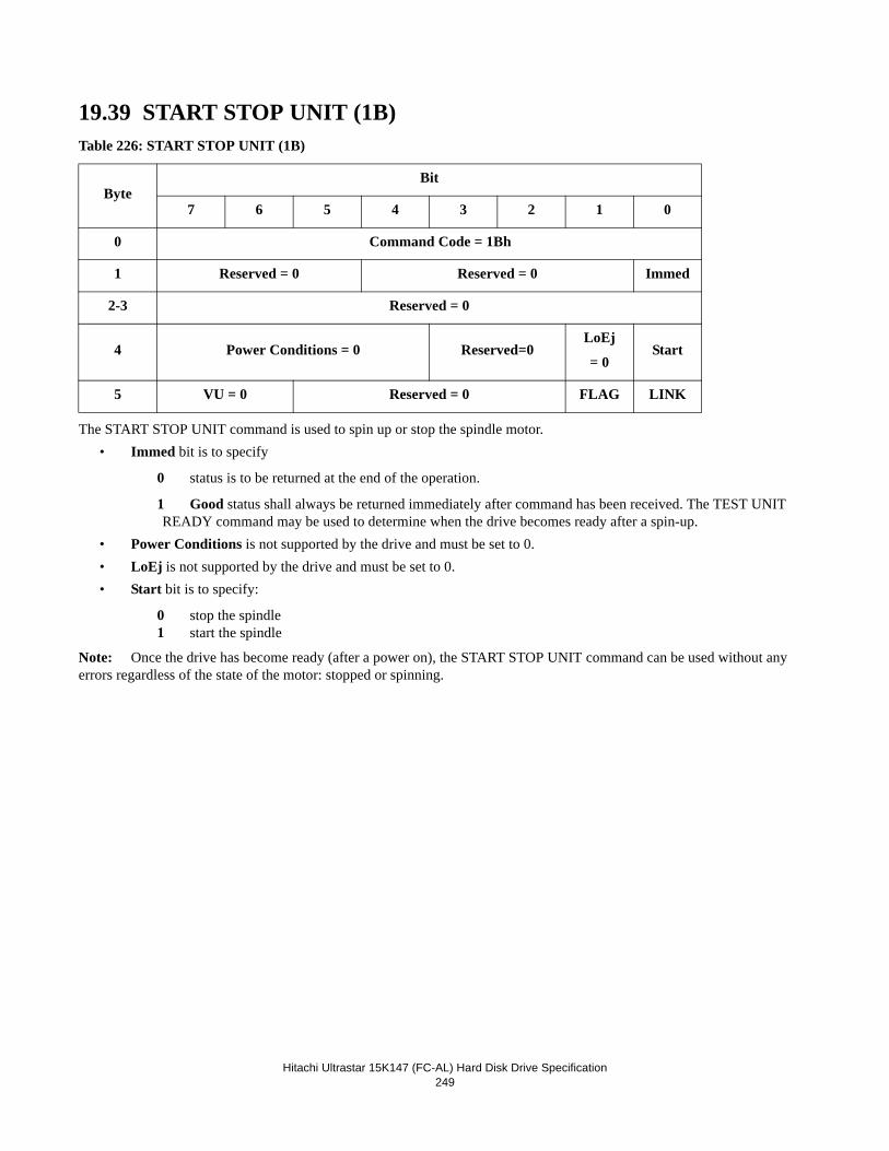
Hitachi Ultrastar 15K147 (FC-AL) Hard Disk Drive Specification249
19.39 START STOP UNIT (1B)Table 226: START STOP UNIT (1B)
The START STOP UNIT command is used to spin up or stop the spindle motor.• Immed bit is to specify
0 status is to be returned at the end of the operation.
1 Good status shall always be returned immediately after command has been received. The TEST UNIT READY command may be used to determine when the drive becomes ready after a spin-up.
• Power Conditions is not supported by the drive and must be set to 0.• LoEj is not supported by the drive and must be set to 0.• Start bit is to specify:
0 stop the spindle1 start the spindle
Note: Once the drive has become ready (after a power on), the START STOP UNIT command can be used without any errors regardless of the state of the motor: stopped or spinning.
ByteBit
7 6 5 4 3 2 1 0
0 Command Code = 1Bh
1 Reserved = 0 Reserved = 0 Immed
2-3 Reserved = 0
4 Power Conditions = 0 Reserved=0LoEj
= 0Start
5 VU = 0 Reserved = 0 FLAG LINK
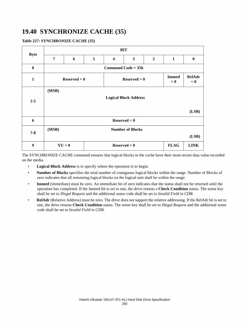
Hitachi Ultrastar 15K147 (FC-AL) Hard Disk Drive Specification250
19.40 SYNCHRONIZE CACHE (35)Table 227: SYNCHRONIZE CACHE (35)
The SYNCHRONIZE CACHE command ensures that logical blocks in the cache have their most recent data value recorded on the media.
• Logical Block Address is to specify where the operation is to begin.• Number of Blocks specifies the total number of contiguous logical blocks within the range. Number of Blocks of
zero indicates that all remaining logical blocks on the logical unit shall be within the range.• Immed (immediate) must be zero. An immediate bit of zero indicates that the status shall not be returned until the
operation has completed. If the Immed bit is set to one, the drive returns a Check Condition status. The sense key shall be set to Illegal Request and the additional sense code shall be set to Invalid Field in CDB.
• RelAdr (Relative Address) must be zero. The drive does not support the relative addressing. If the RelAdr bit is set to one, the drive returns Check Condition status. The sense key shall be set to Illegal Request and the additional sense code shall be set to Invalid Field in CDB.
ByteBIT
7 6 5 4 3 2 1 0
0 Command Code = 35h
1 Reserved = 0 Reserved = 0 Immed = 0
RelAdr = 0
2-5
(MSB)
Logical Block Address
(LSB)
6 Reserved = 0
7-8(MSB) Number of Blocks
(LSB)
9 VU = 0 Reserved = 0 FLAG LINK
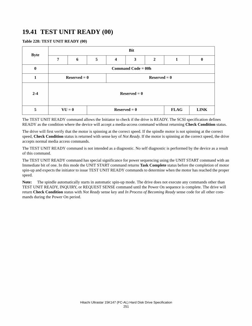
Hitachi Ultrastar 15K147 (FC-AL) Hard Disk Drive Specification251
19.41 TEST UNIT READY (00)Table 228: TEST UNIT READY (00)
The TEST UNIT READY command allows the Initiator to check if the drive is READY. The SCSI specification defines READY as the condition where the device will accept a media-access command without returning Check Condition status.
The drive will first verify that the motor is spinning at the correct speed. If the spindle motor is not spinning at the correct speed, Check Condition status is returned with sense key of Not Ready. If the motor is spinning at the correct speed, the drive accepts normal media access commands.
The TEST UNIT READY command is not intended as a diagnostic. No self diagnostic is performed by the device as a result of this command.
The TEST UNIT READY command has special significance for power sequencing using the UNIT START command with an Immediate bit of one. In this mode the UNIT START command returns Task Complete status before the completion of motor spin-up and expects the initiator to issue TEST UNIT READY commands to determine when the motor has reached the proper speed.
Note: The spindle automatically starts in automatic spin-up mode. The drive does not execute any commands other than TEST UNIT READY, INQUIRY, or REQUEST SENSE command until the Power On sequence is complete. The drive will return Check Condition status with Not Ready sense key and In Process of Becoming Ready sense code for all other com-mands during the Power On period.
ByteBit
7 6 5 4 3 2 1 0
0 Command Code = 00h
1 Reserved = 0 Reserved = 0
2-4 Reserved = 0
5 VU = 0 Reserved = 0 FLAG LINK
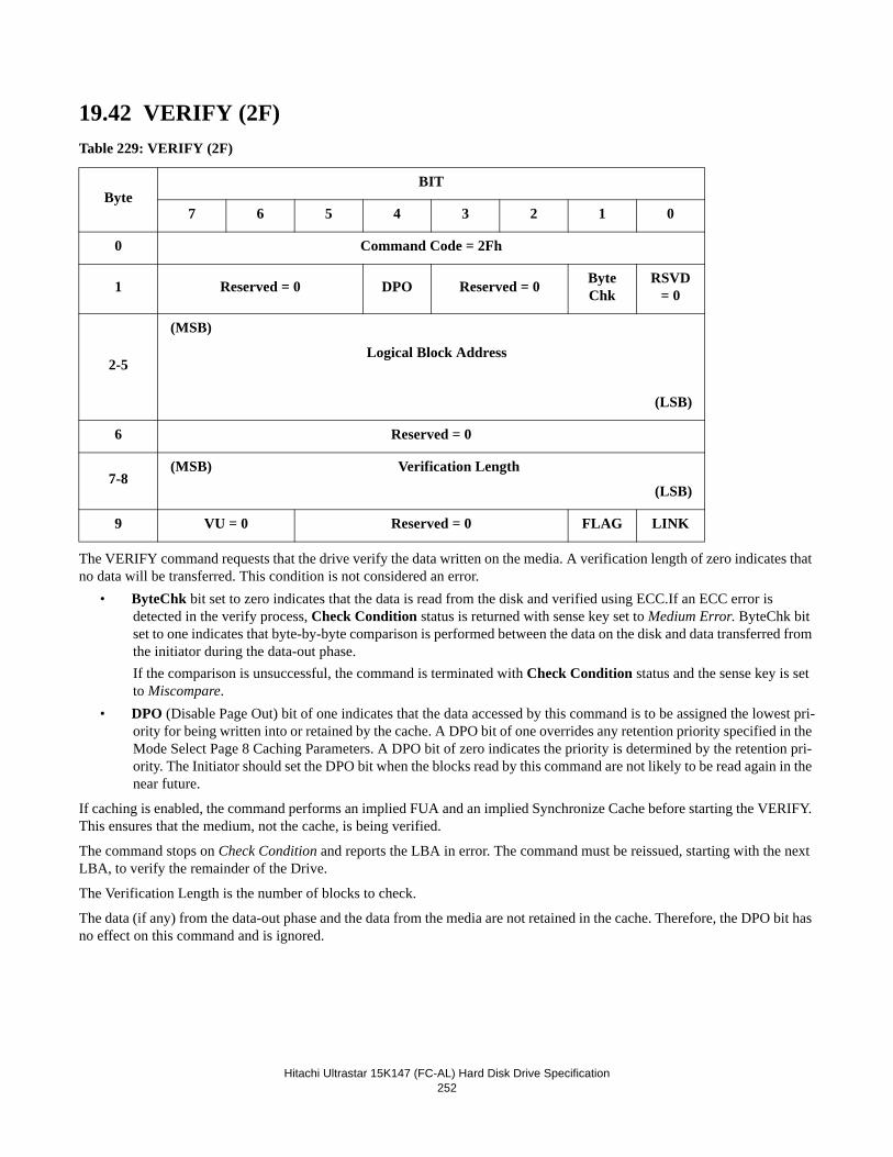
Hitachi Ultrastar 15K147 (FC-AL) Hard Disk Drive Specification252
19.42 VERIFY (2F)Table 229: VERIFY (2F)
The VERIFY command requests that the drive verify the data written on the media. A verification length of zero indicates that no data will be transferred. This condition is not considered an error.
• ByteChk bit set to zero indicates that the data is read from the disk and verified using ECC.If an ECC error is detected in the verify process, Check Condition status is returned with sense key set to Medium Error. ByteChk bit set to one indicates that byte-by-byte comparison is performed between the data on the disk and data transferred from the initiator during the data-out phase.If the comparison is unsuccessful, the command is terminated with Check Condition status and the sense key is set to Miscompare.
• DPO (Disable Page Out) bit of one indicates that the data accessed by this command is to be assigned the lowest pri-ority for being written into or retained by the cache. A DPO bit of one overrides any retention priority specified in the Mode Select Page 8 Caching Parameters. A DPO bit of zero indicates the priority is determined by the retention pri-ority. The Initiator should set the DPO bit when the blocks read by this command are not likely to be read again in the near future.
If caching is enabled, the command performs an implied FUA and an implied Synchronize Cache before starting the VERIFY. This ensures that the medium, not the cache, is being verified.
The command stops on Check Condition and reports the LBA in error. The command must be reissued, starting with the next LBA, to verify the remainder of the Drive.
The Verification Length is the number of blocks to check.
The data (if any) from the data-out phase and the data from the media are not retained in the cache. Therefore, the DPO bit has no effect on this command and is ignored.
ByteBIT
7 6 5 4 3 2 1 0
0 Command Code = 2Fh
1 Reserved = 0 DPO Reserved = 0 ByteChk
RSVD = 0
2-5
(MSB)
Logical Block Address
(LSB)
6 Reserved = 0
7-8(MSB) Verification Length
(LSB)
9 VU = 0 Reserved = 0 FLAG LINK
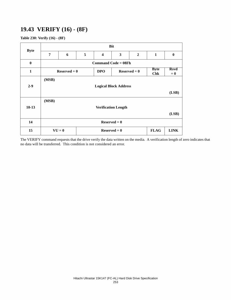
Hitachi Ultrastar 15K147 (FC-AL) Hard Disk Drive Specification253
19.43 VERIFY (16) - (8F)Table 230: Verify (16) - (8F)
The VERIFY command requests that the drive verify the data written on the media. A verification length of zero indicates that no data will be transferred. This condition is not considered an error.
ByteBit
7 6 5 4 3 2 1 0
0 Command Code = 08Fh
1 Reserved = 0 DPO Reserved = 0 Byte Chk
Rsvd = 0
2-9
(MSB)
Logical Block Address
(LSB)
10-13
(MSB)
Verification Length
(LSB)
14 Reserved = 0
15 VU = 0 Reserved = 0 FLAG LINK
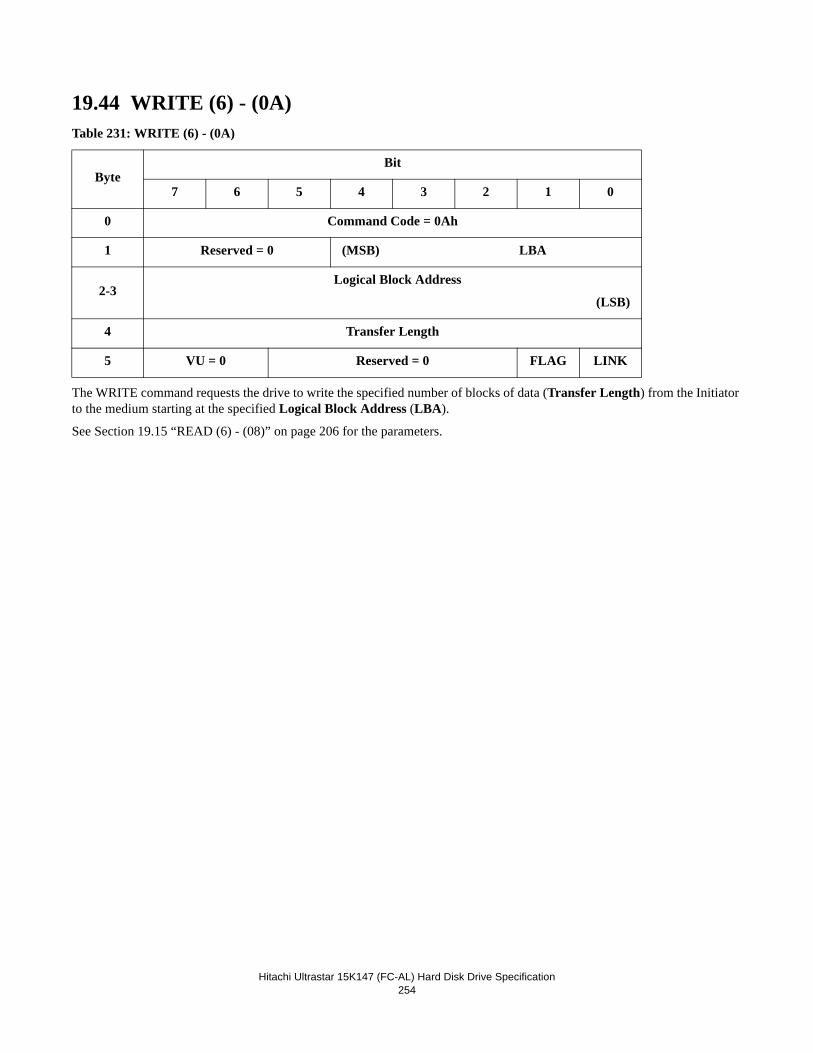
Hitachi Ultrastar 15K147 (FC-AL) Hard Disk Drive Specification254
19.44 WRITE (6) - (0A)Table 231: WRITE (6) - (0A)
The WRITE command requests the drive to write the specified number of blocks of data (Transfer Length) from the Initiator to the medium starting at the specified Logical Block Address (LBA).
See Section 19.15 “READ (6) - (08)” on page 206 for the parameters.
ByteBit
7 6 5 4 3 2 1 0
0 Command Code = 0Ah
1 Reserved = 0 (MSB) LBA
2-3 Logical Block Address
(LSB)
4 Transfer Length
5 VU = 0 Reserved = 0 FLAG LINK
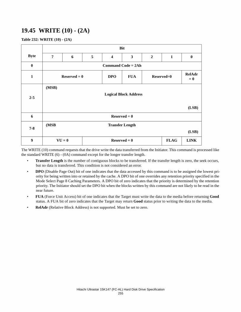
Hitachi Ultrastar 15K147 (FC-AL) Hard Disk Drive Specification255
19.45 WRITE (10) - (2A)Table 232: WRITE (10) - (2A)
The WRITE (10) command requests that the drive write the data transferred from the Initiator. This command is processed like the standard WRITE (6) - (0A) command except for the longer transfer length.
• Transfer Length is the number of contiguous blocks to be transferred. If the transfer length is zero, the seek occurs, but no data is transferred. This condition is not considered an error.
• DPO (Disable Page Out) bit of one indicates that the data accessed by this command is to be assigned the lowest pri-ority for being written into or retained by the cache. A DPO bit of one overrides any retention priority specified in the Mode Select Page 8 Caching Parameters. A DPO bit of zero indicates that the priority is determined by the retention priority. The Initiator should set the DPO bit when the blocks written by this command are not likely to be read in the near future.
• FUA (Force Unit Access) bit of one indicates that the Target must write the data to the media before returning Good status. A FUA bit of zero indicates that the Target may return Good status prior to writing the data to the media.
• RelAdr (Relative Block Address) is not supported. Must be set to zero.
Byte
Bit
7 6 5 4 3 2 1 0
0 Command Code = 2Ah
1 Reserved = 0 DPO FUA Reserved=0 RelAdr = 0
2-5
(MSB)
Logical Block Address
(LSB)
6 Reserved = 0
7-8(MSB Transfer Length
(LSB)
9 VU = 0 Reserved = 0 FLAG LINK
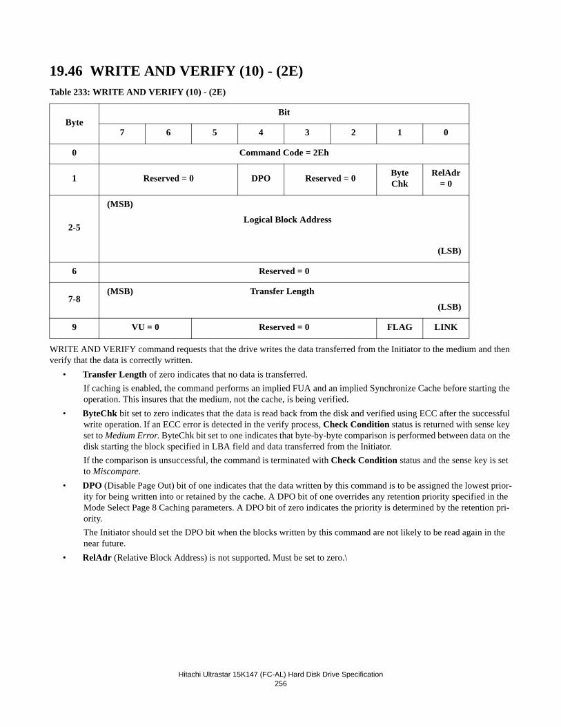
Hitachi Ultrastar 15K147 (FC-AL) Hard Disk Drive Specification256
19.46 WRITE AND VERIFY (10) - (2E)Table 233: WRITE AND VERIFY (10) - (2E)
WRITE AND VERIFY command requests that the drive writes the data transferred from the Initiator to the medium and then verify that the data is correctly written.
• Transfer Length of zero indicates that no data is transferred.If caching is enabled, the command performs an implied FUA and an implied Synchronize Cache before starting the operation. This insures that the medium, not the cache, is being verified.
• ByteChk bit set to zero indicates that the data is read back from the disk and verified using ECC after the successful write operation. If an ECC error is detected in the verify process, Check Condition status is returned with sense key set to Medium Error. ByteChk bit set to one indicates that byte-by-byte comparison is performed between data on the disk starting the block specified in LBA field and data transferred from the Initiator.If the comparison is unsuccessful, the command is terminated with Check Condition status and the sense key is set to Miscompare.
• DPO (Disable Page Out) bit of one indicates that the data written by this command is to be assigned the lowest prior-ity for being written into or retained by the cache. A DPO bit of one overrides any retention priority specified in the Mode Select Page 8 Caching parameters. A DPO bit of zero indicates the priority is determined by the retention pri-ority.The Initiator should set the DPO bit when the blocks written by this command are not likely to be read again in the near future.
• RelAdr (Relative Block Address) is not supported. Must be set to zero.\
ByteBit
7 6 5 4 3 2 1 0
0 Command Code = 2Eh
1 Reserved = 0 DPO Reserved = 0 ByteChk
RelAdr = 0
2-5
(MSB)
Logical Block Address
(LSB)
6 Reserved = 0
7-8(MSB) Transfer Length
(LSB)
9 VU = 0 Reserved = 0 FLAG LINK
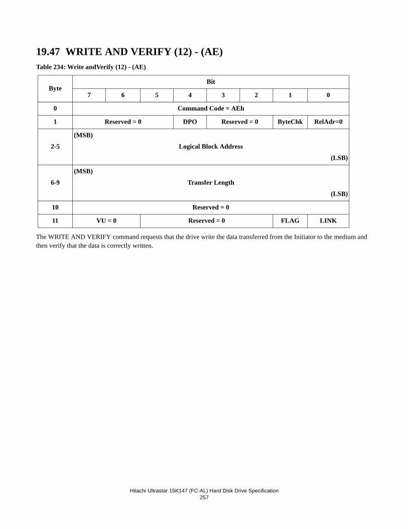
Hitachi Ultrastar 15K147 (FC-AL) Hard Disk Drive Specification257
19.47 WRITE AND VERIFY (12) - (AE)Table 234: Write andVerify (12) - (AE)
The WRITE AND VERIFY command requests that the drive write the data transferred from the Initiator to the medium and then verify that the data is correctly written.
ByteBit
7 6 5 4 3 2 1 0
0 Command Code = AEh
1 Reserved = 0 DPO Reserved = 0 ByteChk RelAdr=0
2-5
(MSB)
Logical Block Address
(LSB)
6-9
(MSB)
Transfer Length
(LSB)
10 Reserved = 0
11 VU = 0 Reserved = 0 FLAG LINK
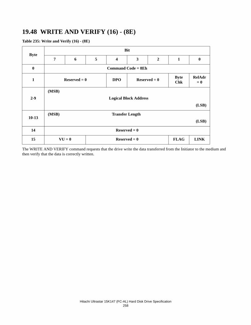
Hitachi Ultrastar 15K147 (FC-AL) Hard Disk Drive Specification258
19.48 WRITE AND VERIFY (16) - (8E)Table 235: Write and Verify (16) - (8E)
The WRITE AND VERIFY command requests that the drive write the data transferred from the Initiator to the medium and then verify that the data is correctly written.
ByteBit
7 6 5 4 3 2 1 0
0 Command Code = 8Eh
1 Reserved = 0 DPO Reserved = 0 ByteChk
RelAdr = 0
2-9
(MSB)
Logical Block Address
(LSB)
10-13(MSB) Transfer Length
(LSB)
14 Reserved = 0
15 VU = 0 Reserved = 0 FLAG LINK
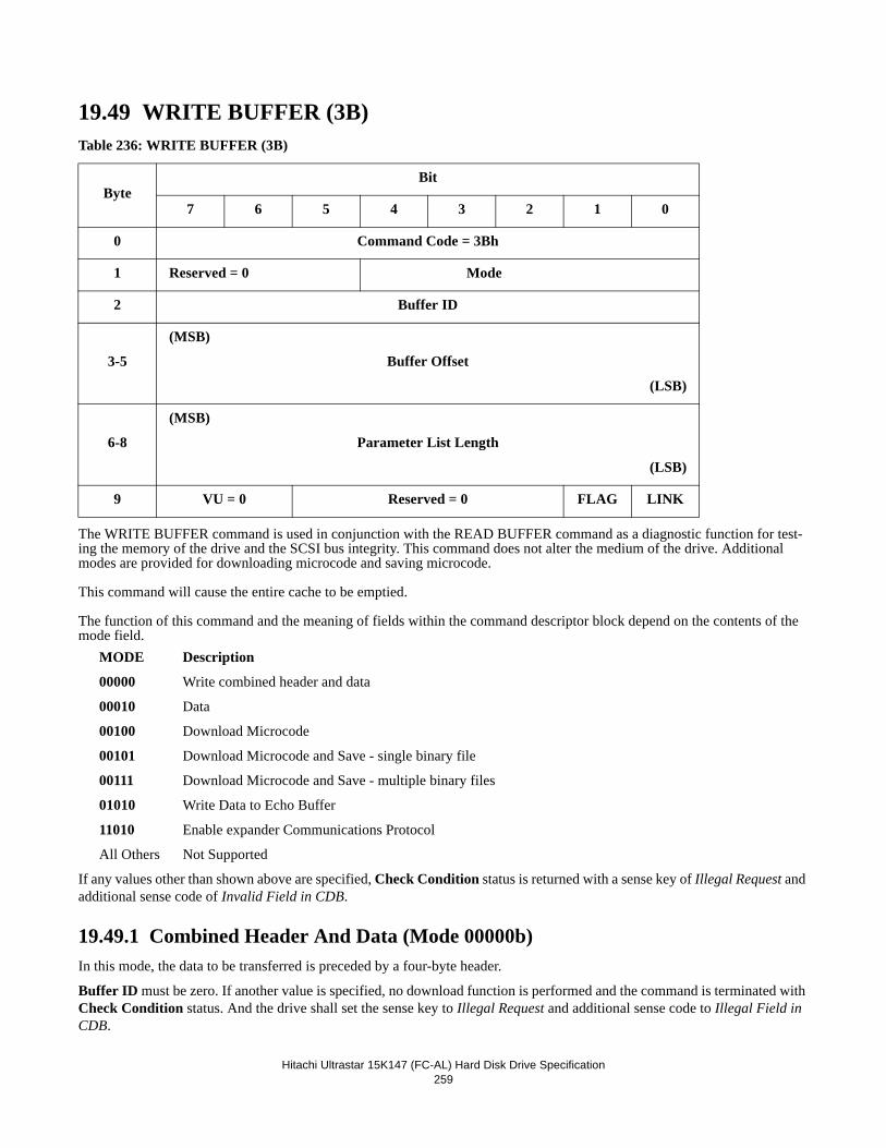
Hitachi Ultrastar 15K147 (FC-AL) Hard Disk Drive Specification259
19.49 WRITE BUFFER (3B)Table 236: WRITE BUFFER (3B)
The WRITE BUFFER command is used in conjunction with the READ BUFFER command as a diagnostic function for test-ing the memory of the drive and the SCSI bus integrity. This command does not alter the medium of the drive. Additional modes are provided for downloading microcode and saving microcode.
This command will cause the entire cache to be emptied.
The function of this command and the meaning of fields within the command descriptor block depend on the contents of the mode field.
MODE Description
00000 Write combined header and data
00010 Data
00100 Download Microcode
00101 Download Microcode and Save - single binary file
00111 Download Microcode and Save - multiple binary files
01010 Write Data to Echo Buffer
11010 Enable expander Communications Protocol
All Others Not Supported
If any values other than shown above are specified, Check Condition status is returned with a sense key of Illegal Request and additional sense code of Invalid Field in CDB.
19.49.1 Combined Header And Data (Mode 00000b)In this mode, the data to be transferred is preceded by a four-byte header.
Buffer ID must be zero. If another value is specified, no download function is performed and the command is terminated with Check Condition status. And the drive shall set the sense key to Illegal Request and additional sense code to Illegal Field in CDB.
ByteBit
7 6 5 4 3 2 1 0
0 Command Code = 3Bh
1 Reserved = 0 Mode
2 Buffer ID
3-5
(MSB)
Buffer Offset
(LSB)
6-8
(MSB)
Parameter List Length
(LSB)
9 VU = 0 Reserved = 0 FLAG LINK
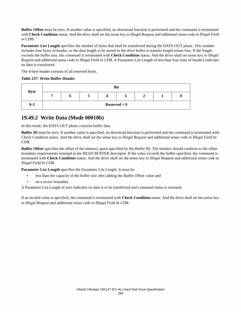
Hitachi Ultrastar 15K147 (FC-AL) Hard Disk Drive Specification260
Buffer Offset must be zero. If another value is specified, no download function is performed and the command is terminated with Check Condition status. And the drive shall set the sense key to Illegal Request and additional sense code to Illegal Field in CDB.
Parameter List Length specifies the number of bytes that shall be transferred during the DATA OUT phase. This number includes four bytes of header, so the data length to be stored in the drive buffer is transfer length minus four. If the length exceeds the buffer size, the command is terminated with Check Condition status. And the drive shall set sense key to Illegal Request and additional sense code to Illegal Field in CDB. A Parameter List Length of less than four (size of header) indicates no data is transferred.
The 4-byte header consists of all reserved bytes.
Table 237: Write Buffer Header
19.49.2 Write Data (Mode 00010b)In this mode, the DATA OUT phase contains buffer data.
Buffer ID must be zero. If another value is specified, no download function is performed and the command is terminated with Check Condition status. And the drive shall set the sense key to Illegal Request and additional sense code to Illegal Field In CDB.
Buffer Offset specifies the offset of the memory space specified by the Buffer ID. The initiator should conform to the offset boundary requirements returned in the READ BUFFER descriptor. If the value exceeds the buffer specified, the command is terminated with Check Condition status. And the drive shall set the sense key to Illegal Request and additional sense code to Illegal Field In CDB.
Parameter List Length specifies the Parameter List Length. It must be• less than the capacity of the buffer size after adding the Buffer Offset value and• on a sector boundary
A Parameter List Length of zero indicates no data is to be transferred and command status is returned.
If an invalid value is specified, the command is terminated with Check Condition status. And the drive shall set the sense key to Illegal Request and additional sense code to Illegal Field In CDB.
ByteBit
7 6 5 4 3 2 1 0
0-3 Reserved = 0
Hitachi Ultrastar 15K147 (FC-AL) Hard Disk Drive Specification261
19.49.3 Download Microcode (Mode 00100b)NOTE: It is not expected that a customer will ever issue this format of the command.
In this mode, the microcode is transferred to the control memory space of the drive. When downloaded, the drive will operate with the newly downloaded code immediately until the next power cycle.
Buffer ID field is used to indicate which portion of the microcode image is being downloaded. The following Buffer IDs are supported by the Target:
- 00h: Main Microprocessor Code
- nnh : ID of Vendor Unique Reserved Area
Any unsupported value for the Buffer ID will cause the command to terminate with Check Condition status. And the drive shall set the sense key to Illegal Request and additional sense code to Illegal Field In CDB.
Buffer Offset must be zero. If an invalid value is specified, the command is terminated with Check Condition status. The drive shall set the sense key to Illegal Request and additional sense code to Illegal Field in CDB.
Parameter List Length must be the size of the data set to be downloaded. It may also be set to 0000h in which case no code is updated and command status is returned. If an invalid value is specified, the command is terminated with Check Condition status. And the drive shall set the sense key to Illegal Request and additional sense code to Illegal Field In CDB.
This process generates a unit attention condition for MICROCODE HAS BEEN CHANGED for all Initiators except the one which sent the WRITE BUFFER command. Upon the completion of the WRITE BUFFER command the new microcode is immediately ready for operation.
Note: The Download Microcode mode described in this specification is to indicate that the drive will accept a command with this mode, though it is not expected that a user will ever issue such a command. To use the write buffer command with this mode, a special microcode version is required from development. If such a microcode is released from development, then it will include appropriate instructions on the function of new microcode and its effect on the drive operations after download.
19.49.4 Download Microcode and Save (Mode 00101b) -Single Binary FileIn this mode the data is transferred to the drive to save into the System reserved area on the disk. This is for functional upgrade and configuration change reflecting the user's requirements and the manufacturer’s reason or both, and it is stored in the media as a permanent copy. The newly downloaded code becomes effective after the drive issues and completes a self-initiated Power On Reset.
Note: It requires up to 30 seconds to update the microcode including the Flash ROM update.
Note: New code to be downloaded to the drive will be provided by development either by request of a customer for an addi-tional function or as a result of a functional change by development. However please note that not all possible fixes or new functions can be applied to a drive in this manner and that there is a very high dependency on the level of ROM code contained within the drive. If an invalid code or a code not compatible with the ROM code is downloaded, the drive will usually reject this code and will continue normal operation. However there is a small possibility that an invalid code will be accepted. If this occurs, the unit usually becomes inoperable and will have to be returned to the manufacturer for recovery.
Buffer ID field is used to indicate which portion of the microcode image is being downloaded. To download microcode, the buffer ID should be set to 00h. Other values are reserved for Hitachi development purposes only.
19.49.5 Download Microprocessor Microcode and Save (Mode 00111b) - Multiple Binary FilesIn this mode the target receives a segment of the binary microcode file. The Parameter List Length (segment length) of each segment shall be a multiple of 8K bytes. The total length of all segments received shall be equal to the total length of the binary microcode file. All segments must be sent in the proper sequential order.
Hitachi Ultrastar 15K147 (FC-AL) Hard Disk Drive Specification262
If an invalid Parameter List Length is specified, Check Condition status is returned with sense key of Illegal Request and additional sense code of Invalid Field in CDB.
The first segment sent in this mode indicates, by default, the first segment of the binary microcode file. If a Check Condition status is returned in this mode, a Buffer ID == 00h in the subsequent Write Buffer command in this mode indicates the first segment of the binary microcode file. Otherwise the Buffer ID field is ignored.
The Buffer Offset field is ignored.
After all segments of the binary microcode file have been received, the drive behavior is the same as Download Microcode and Save (Mode 00101b) - Single Binary File.
19.49.6 Write Data to Echo Buffer (Mode 01010b)In this mode the Target transfers data into the echo buffer. The echo buffer is assigned in the same manner by the Target as it would for a WRITE operation. Data will be sent aligned on 4-byte boundaries.
Upon successful completion of a WRITE BUFFER command the data will be preserved in the echo buffer unless there is an intervening command to any logical unit, in which case it may be changed.
19.49.7 Enable Expander Communications Protocol (Mode 11010b)In this mode the drive behavior is the same as Write Data to Echo Buffer (Mode 0101b).
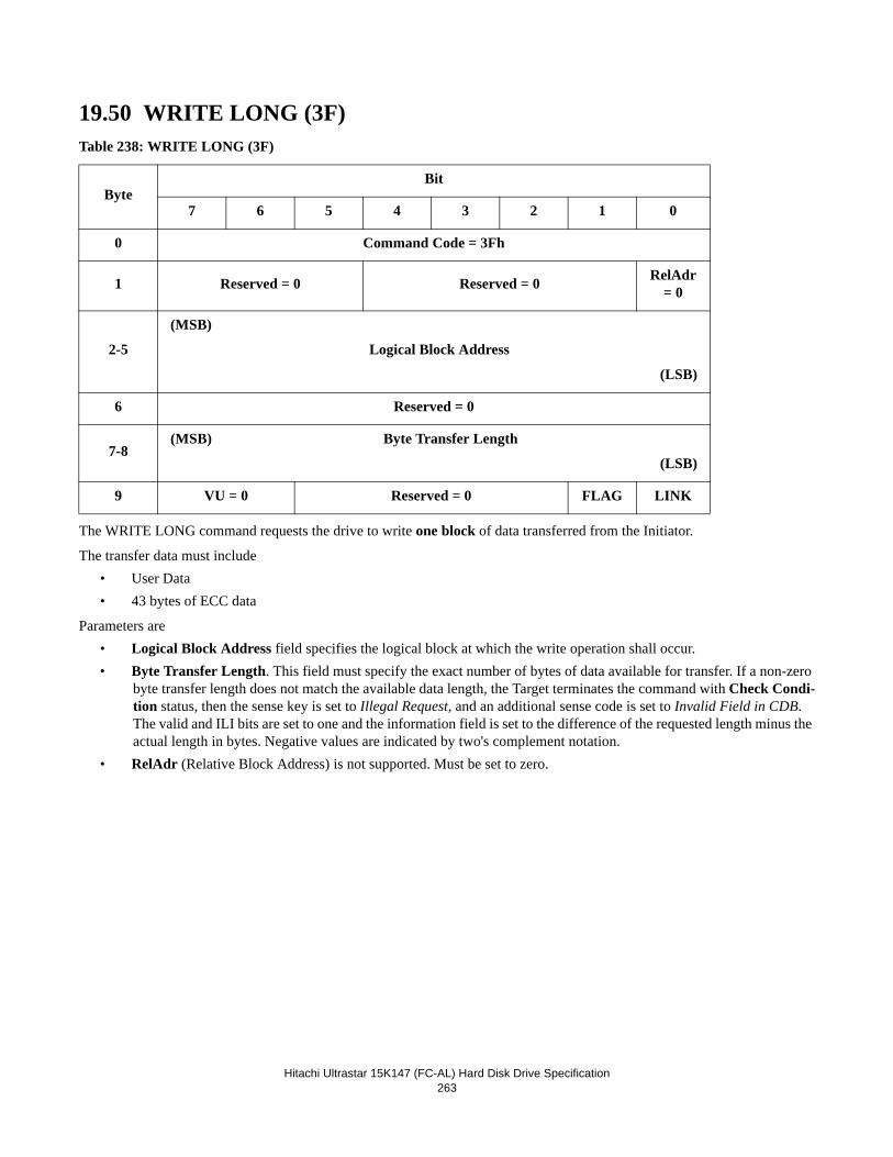
Hitachi Ultrastar 15K147 (FC-AL) Hard Disk Drive Specification263
19.50 WRITE LONG (3F)Table 238: WRITE LONG (3F)
The WRITE LONG command requests the drive to write one block of data transferred from the Initiator.
The transfer data must include• User Data• 43 bytes of ECC data
Parameters are• Logical Block Address field specifies the logical block at which the write operation shall occur.• Byte Transfer Length. This field must specify the exact number of bytes of data available for transfer. If a non-zero
byte transfer length does not match the available data length, the Target terminates the command with Check Condi-tion status, then the sense key is set to Illegal Request, and an additional sense code is set to Invalid Field in CDB. The valid and ILI bits are set to one and the information field is set to the difference of the requested length minus the actual length in bytes. Negative values are indicated by two's complement notation.
• RelAdr (Relative Block Address) is not supported. Must be set to zero.
ByteBit
7 6 5 4 3 2 1 0
0 Command Code = 3Fh
1 Reserved = 0 Reserved = 0 RelAdr = 0
2-5
(MSB)
Logical Block Address
(LSB)
6 Reserved = 0
7-8(MSB) Byte Transfer Length
(LSB)
9 VU = 0 Reserved = 0 FLAG LINK
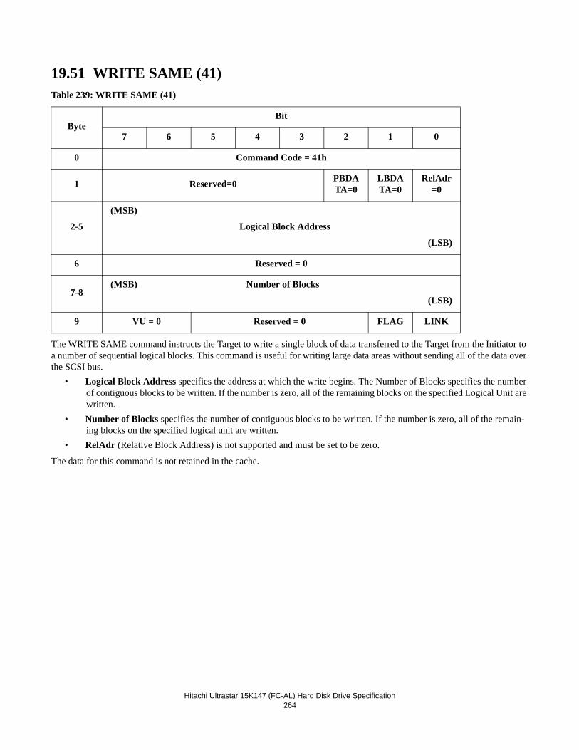
Hitachi Ultrastar 15K147 (FC-AL) Hard Disk Drive Specification264
19.51 WRITE SAME (41)Table 239: WRITE SAME (41)
The WRITE SAME command instructs the Target to write a single block of data transferred to the Target from the Initiator to a number of sequential logical blocks. This command is useful for writing large data areas without sending all of the data over the SCSI bus.
• Logical Block Address specifies the address at which the write begins. The Number of Blocks specifies the number of contiguous blocks to be written. If the number is zero, all of the remaining blocks on the specified Logical Unit are written.
• Number of Blocks specifies the number of contiguous blocks to be written. If the number is zero, all of the remain-ing blocks on the specified logical unit are written.
• RelAdr (Relative Block Address) is not supported and must be set to be zero.
The data for this command is not retained in the cache.
ByteBit
7 6 5 4 3 2 1 0
0 Command Code = 41h
1 Reserved=0 PBDATA=0
LBDATA=0
RelAdr=0
2-5
(MSB)
Logical Block Address
(LSB)
6 Reserved = 0
7-8(MSB) Number of Blocks
(LSB)
9 VU = 0 Reserved = 0 FLAG LINK
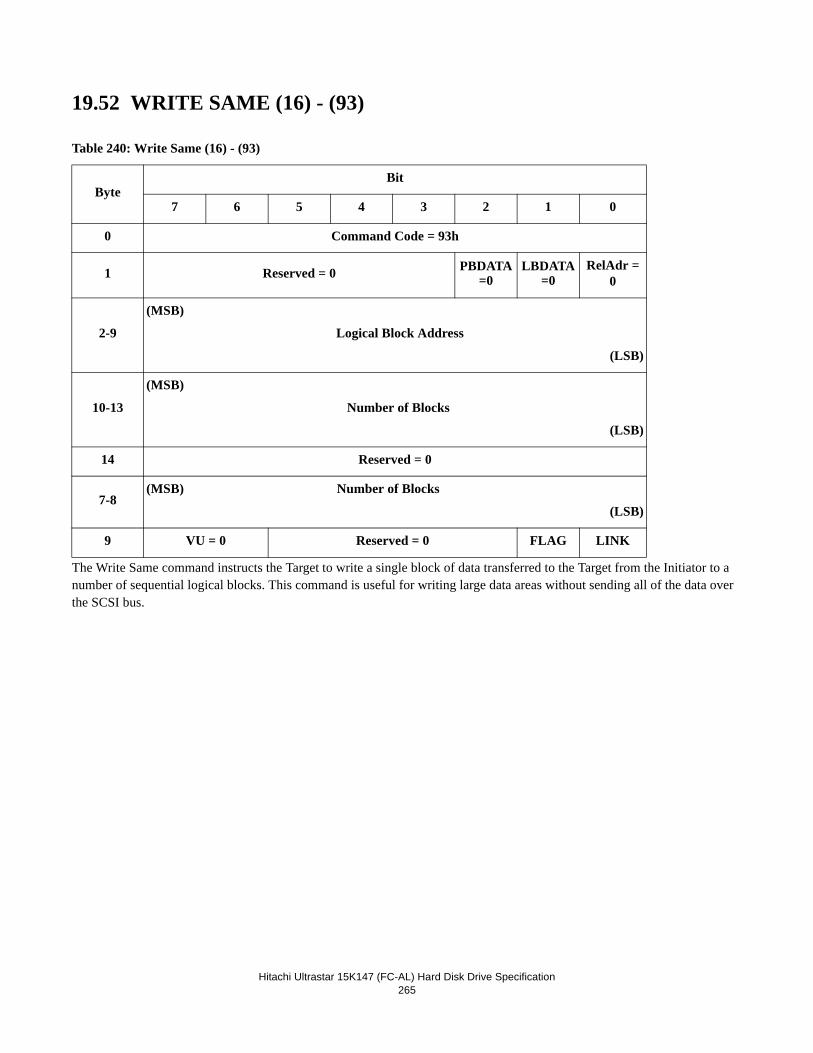
Hitachi Ultrastar 15K147 (FC-AL) Hard Disk Drive Specification265
19.52 WRITE SAME (16) - (93)
The Write Same command instructs the Target to write a single block of data transferred to the Target from the Initiator to a number of sequential logical blocks. This command is useful for writing large data areas without sending all of the data over the SCSI bus.
Table 240: Write Same (16) - (93)
ByteBit
7 6 5 4 3 2 1 0
0 Command Code = 93h
1 Reserved = 0 PBDATA=0
LBDATA=0
RelAdr = 0
2-9
(MSB)
Logical Block Address
(LSB)
10-13
(MSB)
Number of Blocks
(LSB)
14 Reserved = 0
7-8(MSB) Number of Blocks
(LSB)
9 VU = 0 Reserved = 0 FLAG LINK

Hitachi Ultrastar 15K147 (FC-AL) Hard Disk Drive Specification266
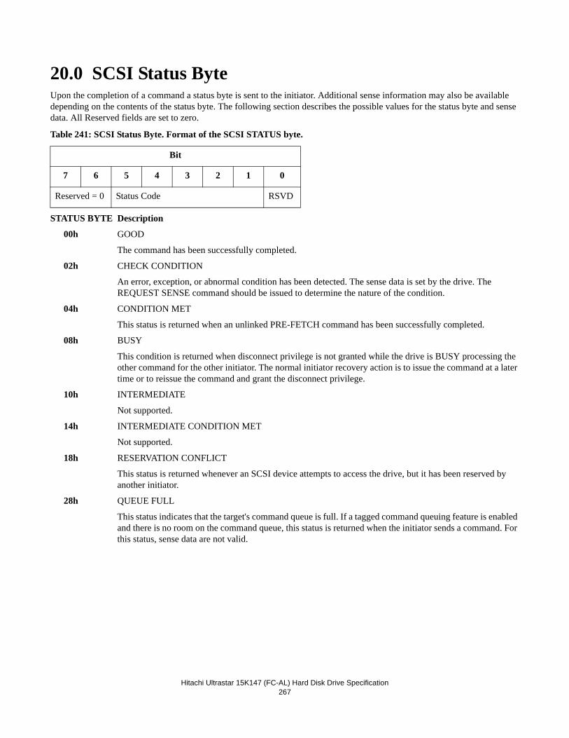
Hitachi Ultrastar 15K147 (FC-AL) Hard Disk Drive Specification267
20.0 SCSI Status ByteUpon the completion of a command a status byte is sent to the initiator. Additional sense information may also be available depending on the contents of the status byte. The following section describes the possible values for the status byte and sense data. All Reserved fields are set to zero.
Table 241: SCSI Status Byte. Format of the SCSI STATUS byte.
STATUS BYTE Description
00h GOOD
The command has been successfully completed.
02h CHECK CONDITION
An error, exception, or abnormal condition has been detected. The sense data is set by the drive. The REQUEST SENSE command should be issued to determine the nature of the condition.
04h CONDITION MET
This status is returned when an unlinked PRE-FETCH command has been successfully completed.
08h BUSY
This condition is returned when disconnect privilege is not granted while the drive is BUSY processing the other command for the other initiator. The normal initiator recovery action is to issue the command at a later time or to reissue the command and grant the disconnect privilege.
10h INTERMEDIATE
Not supported.
14h INTERMEDIATE CONDITION MET
Not supported.
18h RESERVATION CONFLICT
This status is returned whenever an SCSI device attempts to access the drive, but it has been reserved by another initiator.
28h QUEUE FULL
This status indicates that the target's command queue is full. If a tagged command queuing feature is enabled and there is no room on the command queue, this status is returned when the initiator sends a command. For this status, sense data are not valid.
Bit
7 6 5 4 3 2 1 0
Reserved = 0 Status Code RSVD

Hitachi Ultrastar 15K147 (FC-AL) Hard Disk Drive Specification
268
Hitachi Ultrastar 15K147 (FC-AL) Hard Disk Drive Specification269
21.0 Additional informationThis chapter provides additional information or descriptions of various functions, features, or operating models supported by the Target that are not fully described in previous chapters.
21.1 Obtaining an AL_PAThe SCA-2 FC-AL connector used by the drive provides 7 bits which encode a preferred Hard AL_PA for use on both loops. If this value is set to 7Fh, a Soft AL_PA will be used.
Note: Loop Initialization cannot be bypassed if Soft AL_PA is selected.
A Soft AL_PA will also be used if, for any reason, the Hard AL_PA cannot be obtained. If this happens, The drive will
• log out all initiators
• accept new port logins
• accept each process login with a reason code of: 05h
No special action is taken if the connector supplied AL_PA is changed while the drive is participating on the loop(s).
21.2 Loop Initialization ProcedureL_Ports use the Loop Initialization Procedure in order to acquire an AL_PA and participate on the loop.
The drive optionally initiates the Loop Initialization Procedure shortly after power-on, depending on the configured mode set-tings. In addition, it may (depending on the mode settings) initiate the Loop Initialization Procedure for the following reasons:
3. When it has been unable to obtain the loop for E_D_TOV. 4. When a loop failure has been detected (loss of sync for R_T_TOV)
The Loop Initialization Procedure is disruptive to any communication that is actually in progress on the loop. IOPs that are queued or active but without any frames 'in flight' are not affected.
Initiators are not logged out by the Loop Initialization Procedure, but it is their responsibility to login if their AL_PA changes. The drive detects (via the Port_Name) this situation and implicitly ends the prior login. The initiator may perform a 'Port Dis-covery' sequence to check that the targets have not physically changed.
The L_Port that initiates the Loop Initialization Procedure must transmit LIPs for 2 x AL_TIME to ensure that all L_Ports par-ticipate. By default, AL_TIME is set to 15ms.
All L_Ports must provide sufficient buffering to receive and transmit the LIxx frames that are circulated during the Loop Ini-tialization Procedure. The largest of these (LILP and LIRP) have a 132 byte payload and are supported by the drive.
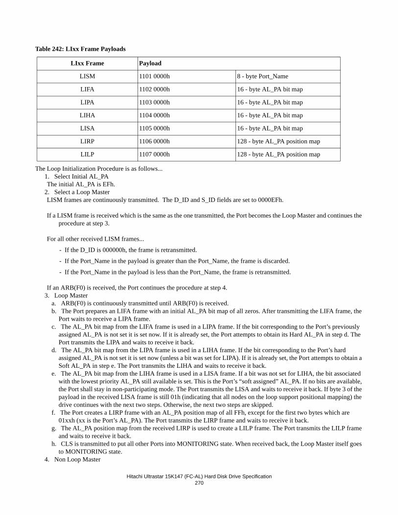
Hitachi Ultrastar 15K147 (FC-AL) Hard Disk Drive Specification270
Table 242: LIxx Frame Payloads
The Loop Initialization Procedure is as follows... 1. Select Initial AL_PA The initial AL_PA is EFh.
2. Select a Loop Master LISM frames are continuously transmitted. The D_ID and S_ID fields are set to 0000EFh.
If a LISM frame is received which is the same as the one transmitted, the Port becomes the Loop Master and continues the procedure at step 3.
For all other received LISM frames...
- If the D_ID is 000000h, the frame is retransmitted.
- If the Port_Name in the payload is greater than the Port_Name, the frame is discarded.
- If the Port_Name in the payload is less than the Port_Name, the frame is retransmitted.
If an ARB(F0) is received, the Port continues the procedure at step 4. 3. Loop Master
a. ARB(F0) is continuously transmitted until ARB(F0) is received. b. The Port prepares an LIFA frame with an initial AL_PA bit map of all zeros. After transmitting the LIFA frame, the
Port waits to receive a LIPA frame. c. The AL_PA bit map from the LIFA frame is used in a LIPA frame. If the bit corresponding to the Port’s previously
assigned AL_PA is not set it is set now. If it is already set, the Port attempts to obtain its Hard AL_PA in step d. The Port transmits the LIPA and waits to receive it back.
d. The AL_PA bit map from the LIPA frame is used in a LIHA frame. If the bit corresponding to the Port’s hard assigned AL_PA is not set it is set now (unless a bit was set for LIPA). If it is already set, the Port attempts to obtain a Soft AL_PA in step e. The Port transmits the LIHA and waits to receive it back.
e. The AL_PA bit map from the LIHA frame is used in a LISA frame. If a bit was not set for LIHA, the bit associated with the lowest priority AL_PA still available is set. This is the Port’s “soft assigned” AL_PA. If no bits are available, the Port shall stay in non-participating mode. The Port transmits the LISA and waits to receive it back. If byte 3 of the payload in the received LISA frame is still 01h (indicating that all nodes on the loop support positional mapping) the drive continues with the next two steps. Otherwise, the next two steps are skipped.
f. The Port creates a LIRP frame with an AL_PA position map of all FFh, except for the first two bytes which are 01xxh (xx is the Port’s AL_PA). The Port transmits the LIRP frame and waits to receive it back.
g. The AL_PA position map from the received LIRP is used to create a LILP frame. The Port transmits the LILP frame and waits to receive it back.
h. CLS is transmitted to put all other Ports into MONITORING state. When received back, the Loop Master itself goes to MONITORING state.
4. Non Loop Master
LIxx Frame Payload
LISM 1101 0000h 8 - byte Port_Name
LIFA 1102 0000h 16 - byte AL_PA bit map
LIPA 1103 0000h 16 - byte AL_PA bit map
LIHA 1104 0000h 16 - byte AL_PA bit map
LISA 1105 0000h 16 - byte AL_PA bit map
LIRP 1106 0000h 128 - byte AL_PA position map
LILP 1107 0000h 128 - byte AL_PA position map
Hitachi Ultrastar 15K147 (FC-AL) Hard Disk Drive Specification271
The Port retransmits received ARB(F0) and prepares to receive the following frames, followed by CLS. a. When a LIFA frame is received, the Port will set the bit corresponding to the Port’s “Fabric Assigned” AL_PA if the
Port was logged-in to the local FL_Port prior to the LIP. (See 21.5, “Public Loop Operation” on page 272.) After transmitting the LIFA frame, The Port waits to receive a LIPA frame.
b. When a LIPA frame is received (and a bit was not set for LIPA), the bit corresponding to any previously assigned AL_PA is checked. If not set, it is set now. If it is already set, the Port attempts to obtain its Hard AL_PA in step c. The Port transmits the LIPA.
c. When a LIHA frame is received (and a bit was not set for LIPA), the bit corresponding to any required hard assigned AL_PA is checked. If not set, it is set now. If it is already set, the Port attempts to obtain a Soft AL_PA in step d. The Port transmits the LIHA.
d. When a LISA frame is received (and a bit was not set for LIHA), the bit associated with the lowest priority AL_PA still available is set. This is the Port’s soft assigned AL_PA. If no bits are available, the Port shall stay in non-partici-pating mode. The Port transmits the LISA.
e. If a LIRP frame is received, and the Port was able to claim an AL_PA in one of the LIxA frames, the left most byte is incremented by one and used as an offset at which to store the Port’s AL_PA. The Port transmits the LIRP.
f. If a LILP frame is received, the Port may store the AL_PA position map for use in error recovery. The Port transmits the LILP.
g. When CLS is received, the Port retransmits it and goes to MONITORING state.
21.3 Flow ControlThe drive provides a Class 3 service. Flow control is maintained using R_RDYs.
Each initiator is required to login with every target. This establishes the Login BB_Credit, (i.e. how many frames the initiator or target may send immediately on opening or being opened.)
Prior to login, BB_Credit is zero.
The Alternate BB_Credit Model is operated as follows...
• On opening, the Available BB_Credit in each direction is set to the agreed Login BB_Credit value.
• Each frame sent decrements the Available BB_Credit and each R_RDY received increments it.
• If the Available BB_Credit reaches zero, the node must stop sending frames until enough R_RDYs have been received to restore positive credit.
• It is permissible to close before credit is balanced (i.e. R_RDY received for each frame sent) but only when enough buffers are available to satisfy the maximum Login BB_Credit that has been extended.
Available BB_Credit may exceed Login BB_Credit but a point to note is that R_RDY is not specific to any frame type. There-fore, the amount of Available BB_Credit that the drive will extend is limited by the amount of buffer space available for FCP_CMND or FCP_DATA IUs. For example, during the execution of a 512K WRITE command, there may be buffer space for 256 2K FCP_DATA IUs and 10 FCP_CMND IUs. The amount of credit extended will be for 10 frames.
21.4 Login RequirementsIn order to communicate effectively, a pair of L_Ports must exchange operational parameters. The same applies to any SCSI processes that use the L_Ports.
The exchange of parameters is called Login and may be either explicit or implicit.
• Explicit Login is the default. L_Ports use the PLOGI Extended Link Service sequence to exchange parameters and SCSI Processes use the PRLI Extended Link Service.
• Implicit Login is enabled via setting of mode page 19h. When enabled, PLOGI and PRLI are not required and a default set of parameters is assumed.
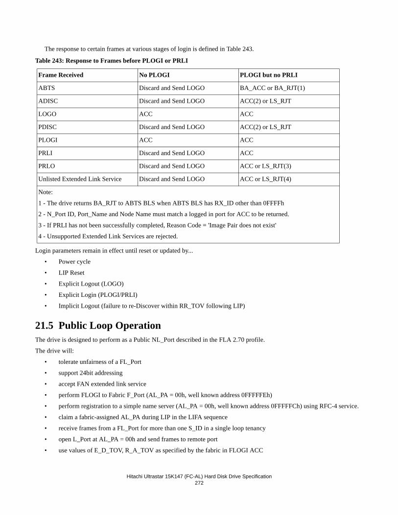
Hitachi Ultrastar 15K147 (FC-AL) Hard Disk Drive Specification272
The response to certain frames at various stages of login is defined in Table 243.
Table 243: Response to Frames before PLOGI or PRLI
Login parameters remain in effect until reset or updated by...
• Power cycle
• LIP Reset
• Explicit Logout (LOGO)
• Explicit Login (PLOGI/PRLI)
• Implicit Logout (failure to re-Discover within RR_TOV following LIP)
21.5 Public Loop OperationThe drive is designed to perform as a Public NL_Port described in the FLA 2.70 profile.
The drive will:
• tolerate unfairness of a FL_Port
• support 24bit addressing
• accept FAN extended link service
• perform FLOGI to Fabric F_Port (AL_PA = 00h, well known address 0FFFFFEh)
• perform registration to a simple name server (AL_PA = 00h, well known address 0FFFFFCh) using RFC-4 service.
• claim a fabric-assigned AL_PA during LIP in the LIFA sequence
• receive frames from a FL_Port for more than one S_ID in a single loop tenancy
• open L_Port at AL_PA = 00h and send frames to remote port
• use values of E_D_TOV, R_A_TOV as specified by the fabric in FLOGI ACC
Frame Received No PLOGI PLOGI but no PRLI
ABTS Discard and Send LOGO BA_ACC or BA_RJT(1)
ADISC Discard and Send LOGO ACC(2) or LS_RJT
LOGO ACC ACC
PDISC Discard and Send LOGO ACC(2) or LS_RJT
PLOGI ACC ACC
PRLI Discard and Send LOGO ACC
PRLO Discard and Send LOGO ACC or LS_RJT(3)
Unlisted Extended Link Service Discard and Send LOGO ACC or LS_RJT(4)
Note:
1 - The drive returns BA_RJT to ABTS BLS when ABTS BLS has RX_ID other than 0FFFFh
2 - N_Port ID, Port_Name and Node Name must match a logged in port for ACC to be returned.
3 - If PRLI has not been successfully completed, Reason Code = 'Image Pair does not exist'
4 - Unsupported Extended Link Services are rejected.
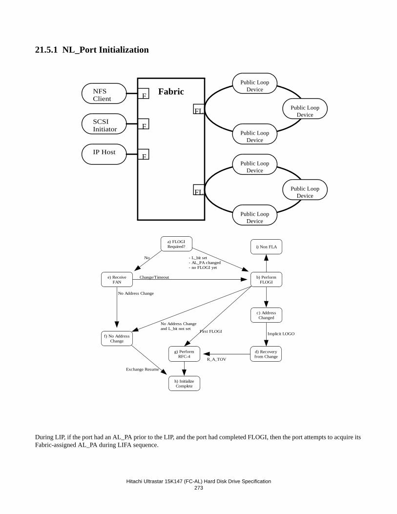
Hitachi Ultrastar 15K147 (FC-AL) Hard Disk Drive Specification273
21.5.1 NL_Port Initialization
During LIP, if the port had an AL_PA prior to the LIP, and the port had completed FLOGI, then the port attempts to acquire its Fabric-assigned AL_PA during LIFA sequence.
Fabric F
F
F
NFSClient
SCSIInitiator
IP Host
FL
FL
Public LoopDevice
Public LoopDevice
Public LoopDevice
Public LoopDevice
Public LoopDevice
Public LoopDevice
e) ReceiveFAN
f) No AddressChange
a) FLOGIRequired? i) Non FLA
b) PerformFLOGI
c) AddressChanged
d) Recoveryfrom Change
g) PerformRFC-4
h) InitializeComplete
No Address Changeand L_bit not set First FLOGI Implicit LOGO
R_A_TOV
Exchange Resume
No Address Change
- L_bit set- AL_PA changed- no FLOGI yet
Change/Timeout
No
Hitachi Ultrastar 15K147 (FC-AL) Hard Disk Drive Specification274
a) FLOGI Required
Upon completion of LIP, the port will implicitly log out with the Fabric and perform FLOGI if one or more of the fol-lowing is true:
• the L_bit was set to one in at least the LISA sequence during the LIP.
• the port did not acquire the AL_PA it had prior to the LIP.
• the port did not have an AL_PA prior to the LIP.
• the port had not completed FLOGI prior to the LIP b) Perform FLOGI
The port attempts to send FLOGI to the FL_Port by opening AL_PA = 00h using Full-Duplex. Meanwhile the port ignores any FAN ELS and responds to ADISC or PLOGI request sequences with an LS_RJT reply sequence, with a Reason code of “Unable to perform Command Request at this time”. If the FLOGI request fails for any reason, the port proceeds to step i). If no address change occurred and the L_bit is not set then the port proceeds to step f). If this is the first FLOGI or if the address has not changed and the L_bit is set, then the port proceeds to step g).
c) Address has changed
The port has determined that its own addressing information and/or that of the FL_Port has changed, or that it did not have completed addressing information (via FLOGI) prior to the initialization. The port discards all pending Exchanges, and performs implicit LOGO with all other ports. The port proceeds to step d).
d) Recovery from address change
The port waits R_A_TOV. During this time the port discards all frame received except for the PLOGI and ADISC request sequences and LOGO ACC reply sequences. The port responds to all PLOGI request with an LS_RJT reply sequence, with a Reason code of “Unable to perform Command Request at this time”. The port responds to each ADISC request sequence with a LOGO request sequence. The port proceeds to step g).
e) Receive FAN
If FLOGI is not required, the port waits E_D_TOV to receive FAN ELS. The port discards all frames received except ADISC and PLOGI requests until FAN is received. The port responds to ADISC and PLOGI request sequences with an LS_RJT reply sequence, with a Reason code of “Unable to perform Command Request at this time”.
After receiving the FAN ELS, if the port determines the FL_Port has the same address, F_Port_Name and Fabric_Name that the FL_Port had before initialization, the port proceeds to f). Otherwise, the port implicitly logs out with the Fabric and proceeds to b).
If the port does not receive a FAN ELS within E_D_TOV the port proceeds to b).
f) Address has not changed
The port resumes all suspended Exchanges with Remote Ports and with Local Ports that are known to be Public NL_Ports. If the port has any suspended Exchanges with Private Loop devices on the Local Loop, the port requires the private loop authentication described in PLDA profile. The port proceeds to step h).
g) Perform RFC-4
The port performs PLOGI with the Directory Server (AL_PA = 00h, well known address 0FFFFFCh) and attempts an RFC-4 request with the Name Service. Regardless of this attempt of RFC-4, the port proceeds to step h).
h) Initialize complete
This completes initialization for the port.
i) Non FLA
The port is not connected to a loop that contains an FL_Port. The port completes initialization based on the rules described in PLDA profile.
Hitachi Ultrastar 15K147 (FC-AL) Hard Disk Drive Specification275
21.6 SCSI ProtocolThere are various operating conditions that prevent the Target from executing a SCSI command. This section describes each of these operating conditions and their relative priority.
21.6.1 Priority of SCSI Status Byte ReportingAfter establishing the I_T_L nexus or I_T_L_Q nexus the Target must first determine whether command execution is allowed. Execution is deferred until a later time if the command must be added to the command queue. Execution may also be pre-vented by an internal Target condition that requires the reporting of a Check Condition, Queue Full, Busy, or Reservation Con-flict Status. There are several different internal conditions to be active at the same time. The order in which the Target checks for each of these conditions determines their priority (highest priority first) as follows:
1. Check Condition status for invalid Logical Unit Number. (See Section 21.6.2, “Invalid LUN Processing” on page 275)2. Check Condition status for Incorrect Initiator Connection (See Section21.6.3, “Overlapped Commands” on page 275)3. Check Condition status for Unit Attention Condition (See Section 21.6.5, “Unit Attention Condition” on page 2774. Busy Status or Queue Full Status (See 21.6.4, “Command Processing During Execution of Active I/O Process” on
page 2765. Check Condition status for Deferred Error Condition (See Section 21.6.8, “Deferred Error Condition” on page 279)6. Check Condition status during Startup and Format operations (See Section “21.6.6, “Command Processing During
Startup and Format Operations” on page 279)7. Reservation Conflict status (See Section 21.6.10, “Command Processing while Reserved” on page 287)8. Check Condition status for invalid command opcode9. Check Condition status for invalid command descriptor block
The highest priority internal condition that prevents command execution is reported by the Target provided there is no bus error.
For all Check Conditions Sense data is built by the target provided a valid LUN address is known. Sense data is cleared by the Target upon receipt of any subsequent command to the LUN from the initiator receiving the Check Condition.
21.6.2 Invalid LUN ProcessingAny value other than zero in the FCP_LUN field of the FCP_CMD IU is invalid.
The target's response to an invalid LUN varies with the command, as follows:
Inquiry: Execute the command, return the INQUIRY data that indicates unknown device type (byte 0 = 7Fh), and return GOOD status. All other bytes are valid (see 19.5, “INQUIRY (12)” on page 124).
Request Sense: Execute the command, return the sense data with the Sense Key set to Illegal Request and the Additional Sense Code and Additional Sense Code Qualifier set to LOGICAL UNIT NOT SUPPORTED, and return GOOD status (see also 19.31, “REQUEST SENSE (03)” on page 239).
All Others: Do not execute the command and return CHECK CONDITION status, along with the auto-sense data with the Sense Key set to Illegal Request and the Additional Sense Code and Additional Sense Code Qualifier set to LOGICAL UNIT NOT SUPPORTED.
In all cases, the target's response to the command for an invalid LUN does not affect the current execution of a command on the valid LUN for this initiator or any other initiator.
21.6.3 Overlapped CommandsFibre Channel Protocol for SCSI Revision 012 (X3.269-1996) says the following: "5.5.9 The value of the OX_ID is the tag defined by X3.270-1996. Since the value of the OX_ID is required by FC-PH to be unique, there is no requirement for an FCP logical unit to check for overlapping commands." Thus the drive does not perform any overlapped command checking.
Hitachi Ultrastar 15K147 (FC-AL) Hard Disk Drive Specification276
21.6.4 Command Processing During Execution of Active I/O Process
When the target is not executing any I/O processes, a new I/O process is permitted to execute (unless execution is prevented by another internal target condition listed in 21.6.1, “Priority of SCSI Status Byte Reporting” on page 275).
If an active I/O process exists when the target receives a new command, then the target determines if:
• the command is permitted to execute
• the command is added to the queue
• Queue Full status is to be returned
• Busy status is to be returned
If an active I/O process exists when the target receives a new command, then the target determines how the new command should be handled based on the following rules:
• Check Condition status is returned with sense key set to Logical Unit Not Ready if:
• the startup operation or a format operation is active. See 21.6.6, “Command Processing During Startup and For-mat Operations” on page 279 for the exact conditions which cause this response.
Note: If a Unit Attention is pending when this condition exists, the sense key is set to Unit Attention rather than Logical Unit Not Ready since Unit Attention has a higher reporting priority (see 21.6.1, “Priority of SCSI Status Byte Reporting” on page 275).
• The command is permitted to execute if:
• the command is a priority command (see 21.7, “Priority Commands” on page 287).
• the conditions to execute concurrently are met (see 21.10, “Concurrent I/O Process” on page 288).
• The command is added to the queue if:
• any I/O process already exists at the target, and
• this is not an incorrect initiator connection.
• Queue Full status is returned if:
• the command would otherwise be added to the queue (according to the rules described above), but all slots in the queue are full, or
• the command would otherwise be added to the queue (according to the rules described above), but all of the available queue slots not reserved for use by another initiator are full, or
• a Format Unit command was previously queued but has not yet begun execution, or
• the target is in a Degraded Mode (see 21.6.9, “Degraded Mode” on page 280) and a Start Unit command was pre-viously queued but has not yet begun execution.
• Busy status is never returned.
Hitachi Ultrastar 15K147 (FC-AL) Hard Disk Drive Specification277
21.6.5 Unit Attention Condition
The target generates a unit attention condition when one of the following occurs: • The target has been reset
This includes a power-on reset or a reset caused by a Target Reset Task Management function or Reset LIP. In all of these cases, a unit attention condition is generated for each initiator. In addition, a process login (PRLI) will cause a Unit Attention Condition Power-On Reset for that initiator with an Additional Sense Code and Additional Sense Code Qualifier reported as Power-On Reset, Power-On Reset Occurred.
• MODE SELECT command has been executed
In this case, a unit attention condition is generated for all initiators except the one that issued the MODE SELECT command. The Additional Sense Code and Additional Sense Code Qualifier reported is MODE PARAMETERS CHANGED. The unit attention condition is generated if any of the current page parameters are set by the MODE SELECT command. The target does not check to see that the old parameters are different from the new parameters. For example: If the initiator issues a MODE SENSE command with a page code to report the current values followed by a MODE SELECT command with the same parameter list, a unit attention condition is generated despite the fact that the current parameters were not changed from their previous value. However, if the target detects an illegal parameter or error condition prior to modifying the current parameters, a unit attention condition is not generated since the parameters were not set. The unit attention condition is also not generated if the MODE SELECT command parameter list does not include any pages and only the header or header/block descriptor is present.
• FORMAT UNIT command has been executed
In this case, a unit attention condition is generated for all initiators except the one that issued the FORMAT UNIT command. The Additional Sense Code and Additional Sense Code Qualifier reported is NOT READY TO READY TRANSITION, (MEDIUM MAY HAVE CHANGED). This indicates that the block descriptor parameters from the last MODE SELECT command have been used and are now considered current values.
• WRITE BUFFER command to download microcode has been executed
In this case, a unit attention condition is generated for all initiators except the one that issued the WRITE BUFFER command. The Additional Sense Code and Additional Sense Code Qualifier reported is MICROCODE HAS BEEN CHANGED.
• Commands Cleared by another initiator
This unit attention condition is generated after an initiator sends a Clear Task Set Task Management function. The unit attention condition is generated for all other initiators with I/O processes that were either active or queued for the logical unit. The Additional Sense Code and Additional Sense Code Qualifier reported is COMMANDS CLEARED BY ANOTHER INITIATOR.
• LOG SELECT command with PCR bit has cleared parameters.
In this case, a unit attention condition is generated for all initiators except the one that issued the LOG SELECT command. The additional sense code and additional sense code qualifier reported is Log Select Parameters Changed.
• The registration or reservation made by a Persistent Reserve Out command was cleared by another initiator.
In this case, a unit attention condition is generated for the initiator that held the cleared registration or reservation.
• A Predictive Failure Analysis threshold has been reached and the Method of Reporting field of mode page 1Ch is 2h.
Hitachi Ultrastar 15K147 (FC-AL) Hard Disk Drive Specification278
The unit attention condition persists for each initiator until that initiator clears the condition from the logical unit as described below. Several commands are handled as special cases during a unit attention condition These cases are also discussed below.
If the target receives a command from an initiator before reporting a CHECK CONDITION status for a pending unit attention condition for that initiator, the target's response varies with the command as follows: Inquiry Execute the command, return GOOD status, and preserve the unit attention condition.
Report Luns Same as above
Request Sense Execute the command, return any pending sense data, return GOOD status, and preserve the unit attention condition. If there is not any pending sense data, the sense data associated with the highest priority unit attention condition is returned and the highest priority unit attention condition is cleared for this initiator.
All Others Do not execute the command, return a CHECK CONDITION status, clear the highest priority unit attention condition for this initiator and return the associated sense data.
More than one unit attention condition may be generated for an initiator before that initiator clears the unit attention condition.
Hitachi Ultrastar 15K147 (FC-AL) Hard Disk Drive Specification279
21.6.6 Command Processing During Startup and Format OperationsIf the Target receives a command from an Initiator while the Target is executing a startup or format operation, the response of the Target varies with the command as follows:
INQUIRY The drive sends inquiry data and returns appropriate status.
REQUEST SENSE Executes the command, returns a Sense key of NOT READY and an Additional Sense Code of LOGICAL UNIT NOT READY and returns GOOD STATUS.
The Additional Sense Code Qualifier that is returned depends on type of I/O processes that are active:
For the START/UNIT STOP and the Auto-start operation, the qualifier returned is LOGICAL UNIT IS IN PROCESS OF BECOMING READY. For the FORMAT UNIT command, the quali-fier returned is LOGICAL UNIT NOT READY, FORMAT IN PROGRESS, and the Sense key spe-cific bytes are set to return the progress indication.
REPORT LUNS The drive sends REPORT LUNS data and approprate status.
ALL OTHER The drive terminates the command with CHECK CONDITION status. The Sense data generated is described in Request Sense above.
21.6.7 Internal Error ConditionThe Target generates an Internal Error condition for all Initiators when an internally initiated operation ends with an unrecov-erable error, that is, the startup sequence for Auto Start enabled terminates after the SCSI bus has been enabled and prior to completion of the bring-up sequence.
An Internal Error condition causes Sense data to be generated and saved for all Initiators. The Error Code field of the Sense is set for a Current Error (70h) and the Sense Key is set to HARDWARE ERROR. Recovered errors are not reported.
The Internal Error condition persists for each Initiator until that Initiator clears the condition from the logical unit as described below. Several commands are handled as special cases during an Internal Error condition. These cases are also discussed.
If the Target receives a command from an Initiator while an Internal Error condition exists for that Initiator, the response of the Target varies with the command as follows:
INQUIRY The drive executes the command with GOOD status and does not clear the Internal Error condition.
REQUEST SENSE The drive executes the command, returns the sense data generated by the Internal Error condition, returns Good Status, and clears the Internal Error condition for that Initiator.
ALL OTHER The drive terminates the command with a CHECK CONDITION status and clears the Internal Error condition.
21.6.8 Deferred Error ConditionError code (71h) of sense data indicates that the Check Condition status returned is the result of an error or exception condition that occurred during execution of a previous command for which Good status has already been returned.
The drive creates an Deferred Error condition when
• Execution of a Format Unit command with the immediate bit of one ends with an error.
• Execution of a Write command with WCE (Write Cache Enable) bit of one ends with an error.
Hitachi Ultrastar 15K147 (FC-AL) Hard Disk Drive Specification280
21.6.9 Degraded ModeThere are certain errors or conditions which may impair the ability of the drive to function normally. Rather than fail hard the drive is designed to be as responsive as possible. Also, in most cases, some action on the part of the initiator may be used to restore normal operation. This mode of limited operation is called Degraded Mode.
There are 3 conditions in the Degraded Mode:
• Spindle Motor Degrade which is caused by one of the following conditions:
- Spindle Motor is not started by the option jumper setting (Disable Auto Spin Up)
- Spindle Motor is delayed from spinning up by the option jumper setting (Auto Start Delay)
- Spindle Motor was started (by POR or Unit Start command) and the Target is under Self Configuration.
- Spindle Motor Failed to start.
- Spindle Motor was stopped by Unit Stop command after the Target successfully completed the Self Configuration.
• Self Configuration Failure Degraded which is caused by one of the following conditions:
- RAM Code, Configuration Sector Read Failure
- RAM Code, Configuration Sector Revision Mismatch
• Format Command Failure Degraded. This condition is caused when Format Unit command failed or was interrupted abnormally (Mode Page 0, byte 5, bit 4 FDD controls Format Degraded mode)
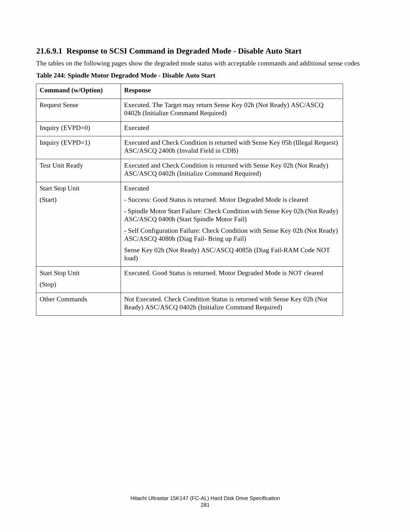
Hitachi Ultrastar 15K147 (FC-AL) Hard Disk Drive Specification281
21.6.9.1 Response to SCSI Command in Degraded Mode - Disable Auto StartThe tables on the following pages show the degraded mode status with acceptable commands and additional sense codes
Table 244: Spindle Motor Degraded Mode - Disable Auto Start
Command (w/Option) Response
Request Sense Executed. The Target may return Sense Key 02h (Not Ready) ASC/ASCQ 0402h (Initialize Command Required)
Inquiry (EVPD=0) Executed
Inquiry (EVPD=1) Executed and Check Condition is returned with Sense Key 05h (Illegal Request) ASC/ASCQ 2400h (Invalid Field in CDB)
Test Unit Ready Executed and Check Condition is returned with Sense Key 02h (Not Ready) ASC/ASCQ 0402h (Initialize Command Required)
Start Stop Unit
(Start)
Executed
- Success: Good Status is returned. Motor Degraded Mode is cleared
- Spindle Motor Start Failure: Check Condition with Sense Key 02h (Not Ready) ASC/ASCQ 0400h (Start Spindle Motor Fail)
- Self Configuration Failure: Check Condition with Sense Key 02h (Not Ready) ASC/ASCQ 4080h (Diag Fail- Bring up Fail)
Sense Key 02h (Not Ready) ASC/ASCQ 4085h (Diag Fail-RAM Code NOT load)
Start Stop Unit
(Stop)
Executed. Good Status is returned. Motor Degraded Mode is NOT cleared
Other Commands Not Executed. Check Condition Status is returned with Sense Key 02h (Not Ready) ASC/ASCQ 0402h (Initialize Command Required)
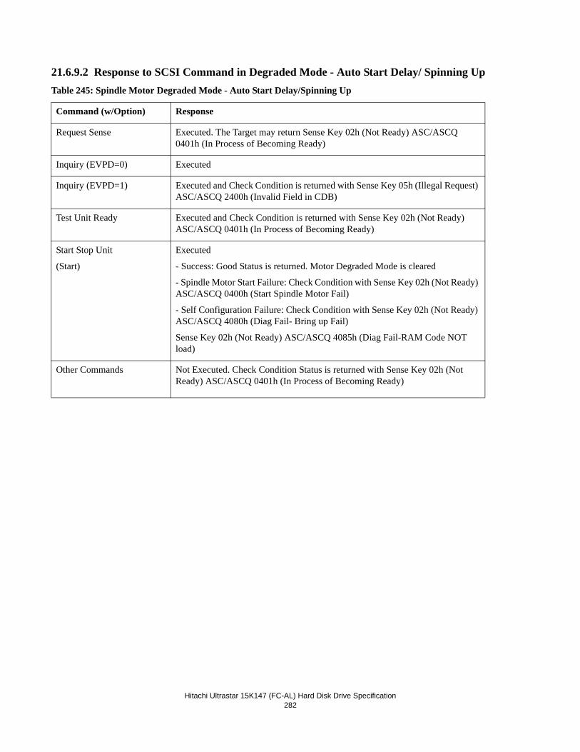
Hitachi Ultrastar 15K147 (FC-AL) Hard Disk Drive Specification282
21.6.9.2 Response to SCSI Command in Degraded Mode - Auto Start Delay/ Spinning UpTable 245: Spindle Motor Degraded Mode - Auto Start Delay/Spinning Up
Command (w/Option) Response
Request Sense Executed. The Target may return Sense Key 02h (Not Ready) ASC/ASCQ 0401h (In Process of Becoming Ready)
Inquiry (EVPD=0) Executed
Inquiry (EVPD=1) Executed and Check Condition is returned with Sense Key 05h (Illegal Request) ASC/ASCQ 2400h (Invalid Field in CDB)
Test Unit Ready Executed and Check Condition is returned with Sense Key 02h (Not Ready) ASC/ASCQ 0401h (In Process of Becoming Ready)
Start Stop Unit
(Start)
Executed
- Success: Good Status is returned. Motor Degraded Mode is cleared
- Spindle Motor Start Failure: Check Condition with Sense Key 02h (Not Ready) ASC/ASCQ 0400h (Start Spindle Motor Fail)
- Self Configuration Failure: Check Condition with Sense Key 02h (Not Ready) ASC/ASCQ 4080h (Diag Fail- Bring up Fail)
Sense Key 02h (Not Ready) ASC/ASCQ 4085h (Diag Fail-RAM Code NOT load)
Other Commands Not Executed. Check Condition Status is returned with Sense Key 02h (Not Ready) ASC/ASCQ 0401h (In Process of Becoming Ready)
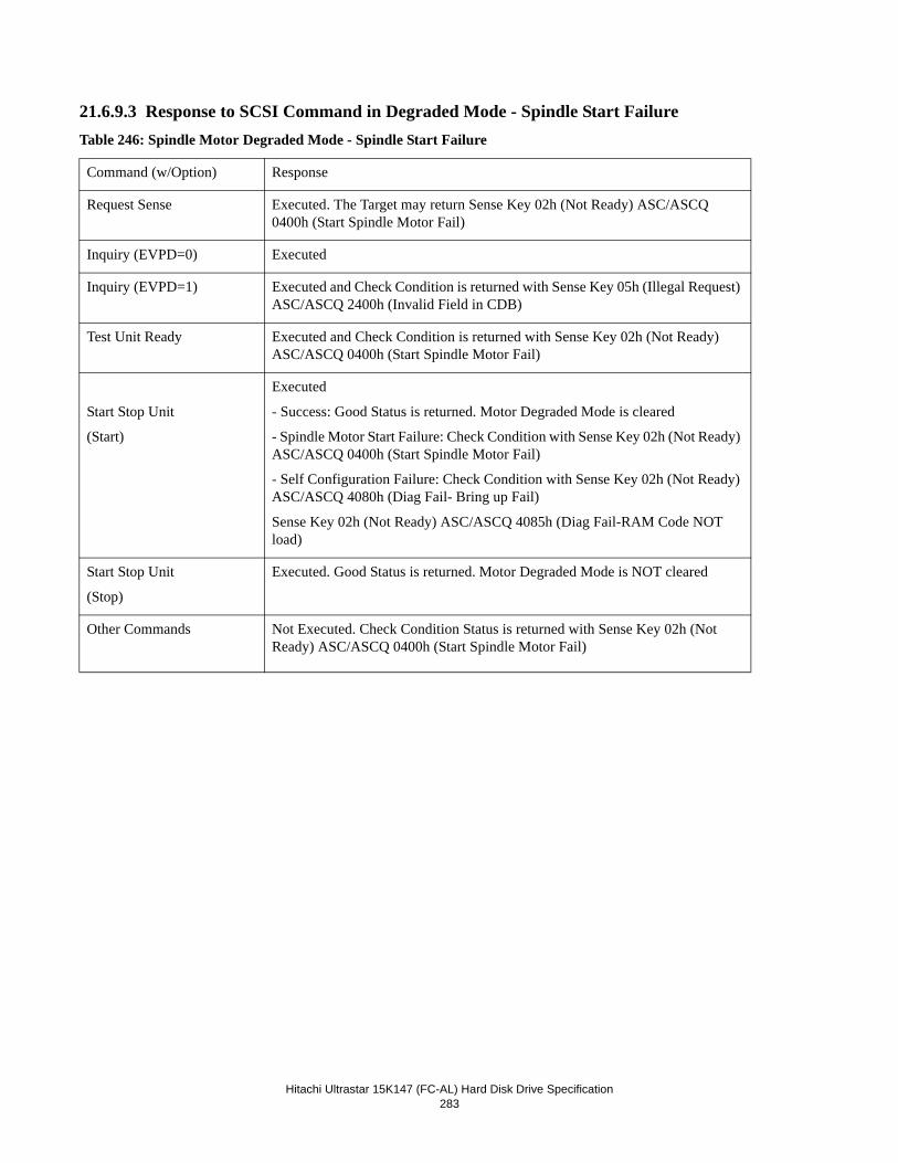
Hitachi Ultrastar 15K147 (FC-AL) Hard Disk Drive Specification283
21.6.9.3 Response to SCSI Command in Degraded Mode - Spindle Start FailureTable 246: Spindle Motor Degraded Mode - Spindle Start Failure
Command (w/Option) Response
Request Sense Executed. The Target may return Sense Key 02h (Not Ready) ASC/ASCQ 0400h (Start Spindle Motor Fail)
Inquiry (EVPD=0) Executed
Inquiry (EVPD=1) Executed and Check Condition is returned with Sense Key 05h (Illegal Request) ASC/ASCQ 2400h (Invalid Field in CDB)
Test Unit Ready Executed and Check Condition is returned with Sense Key 02h (Not Ready) ASC/ASCQ 0400h (Start Spindle Motor Fail)
Start Stop Unit
(Start)
Executed
- Success: Good Status is returned. Motor Degraded Mode is cleared
- Spindle Motor Start Failure: Check Condition with Sense Key 02h (Not Ready) ASC/ASCQ 0400h (Start Spindle Motor Fail)
- Self Configuration Failure: Check Condition with Sense Key 02h (Not Ready) ASC/ASCQ 4080h (Diag Fail- Bring up Fail)
Sense Key 02h (Not Ready) ASC/ASCQ 4085h (Diag Fail-RAM Code NOT load)
Start Stop Unit
(Stop)
Executed. Good Status is returned. Motor Degraded Mode is NOT cleared
Other Commands Not Executed. Check Condition Status is returned with Sense Key 02h (Not Ready) ASC/ASCQ 0400h (Start Spindle Motor Fail)
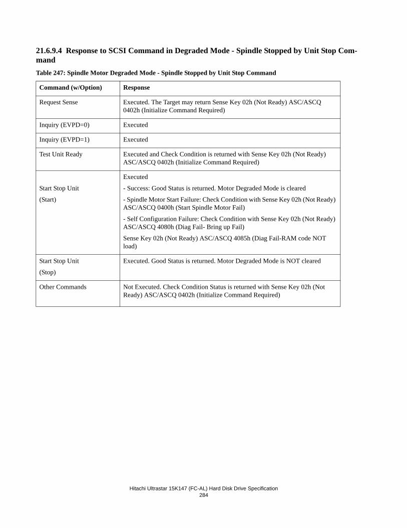
Hitachi Ultrastar 15K147 (FC-AL) Hard Disk Drive Specification284
21.6.9.4 Response to SCSI Command in Degraded Mode - Spindle Stopped by Unit Stop Com-mandTable 247: Spindle Motor Degraded Mode - Spindle Stopped by Unit Stop Command
Command (w/Option) Response
Request Sense Executed. The Target may return Sense Key 02h (Not Ready) ASC/ASCQ 0402h (Initialize Command Required)
Inquiry (EVPD=0) Executed
Inquiry (EVPD=1) Executed
Test Unit Ready Executed and Check Condition is returned with Sense Key 02h (Not Ready) ASC/ASCQ 0402h (Initialize Command Required)
Start Stop Unit
(Start)
Executed
- Success: Good Status is returned. Motor Degraded Mode is cleared
- Spindle Motor Start Failure: Check Condition with Sense Key 02h (Not Ready) ASC/ASCQ 0400h (Start Spindle Motor Fail)
- Self Configuration Failure: Check Condition with Sense Key 02h (Not Ready) ASC/ASCQ 4080h (Diag Fail- Bring up Fail)
Sense Key 02h (Not Ready) ASC/ASCQ 4085h (Diag Fail-RAM code NOT load)
Start Stop Unit
(Stop)
Executed. Good Status is returned. Motor Degraded Mode is NOT cleared
Other Commands Not Executed. Check Condition Status is returned with Sense Key 02h (Not Ready) ASC/ASCQ 0402h (Initialize Command Required)
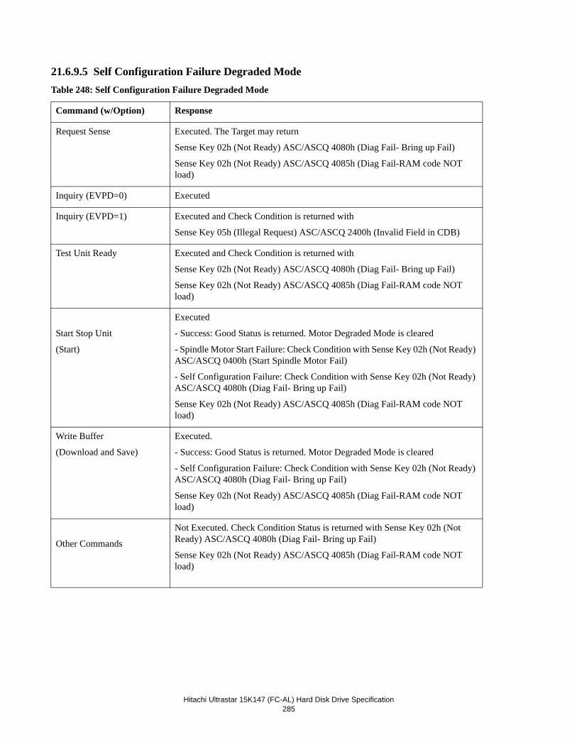
Hitachi Ultrastar 15K147 (FC-AL) Hard Disk Drive Specification285
21.6.9.5 Self Configuration Failure Degraded ModeTable 248: Self Configuration Failure Degraded Mode
Command (w/Option) Response
Request Sense Executed. The Target may return
Sense Key 02h (Not Ready) ASC/ASCQ 4080h (Diag Fail- Bring up Fail)
Sense Key 02h (Not Ready) ASC/ASCQ 4085h (Diag Fail-RAM code NOT load)
Inquiry (EVPD=0) Executed
Inquiry (EVPD=1) Executed and Check Condition is returned with
Sense Key 05h (Illegal Request) ASC/ASCQ 2400h (Invalid Field in CDB)
Test Unit Ready Executed and Check Condition is returned with
Sense Key 02h (Not Ready) ASC/ASCQ 4080h (Diag Fail- Bring up Fail)
Sense Key 02h (Not Ready) ASC/ASCQ 4085h (Diag Fail-RAM code NOT load)
Start Stop Unit
(Start)
Executed
- Success: Good Status is returned. Motor Degraded Mode is cleared
- Spindle Motor Start Failure: Check Condition with Sense Key 02h (Not Ready) ASC/ASCQ 0400h (Start Spindle Motor Fail)
- Self Configuration Failure: Check Condition with Sense Key 02h (Not Ready) ASC/ASCQ 4080h (Diag Fail- Bring up Fail)
Sense Key 02h (Not Ready) ASC/ASCQ 4085h (Diag Fail-RAM code NOT load)
Write Buffer
(Download and Save)
Executed.
- Success: Good Status is returned. Motor Degraded Mode is cleared
- Self Configuration Failure: Check Condition with Sense Key 02h (Not Ready) ASC/ASCQ 4080h (Diag Fail- Bring up Fail)
Sense Key 02h (Not Ready) ASC/ASCQ 4085h (Diag Fail-RAM code NOT load)
Other Commands
Not Executed. Check Condition Status is returned with Sense Key 02h (Not Ready) ASC/ASCQ 4080h (Diag Fail- Bring up Fail)
Sense Key 02h (Not Ready) ASC/ASCQ 4085h (Diag Fail-RAM code NOT load)
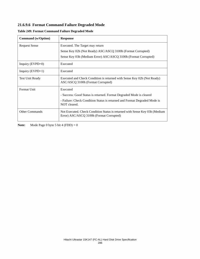
Hitachi Ultrastar 15K147 (FC-AL) Hard Disk Drive Specification286
21.6.9.6 Format Command Failure Degraded ModeTable 249: Format Command Failure Degraded Mode
Note: Mode Page 0 byte 5 bit 4 (FDD) = 0
Command (w/Option) Response
Request Sense Executed. The Target may return
Sense Key 02h (Not Ready) ASC/ASCQ 3100h (Format Corrupted)
Sense Key 03h (Medium Error) ASC/ASCQ 3100h (Format Corrupted)
Inquiry (EVPD=0) Executed
Inquiry (EVPD=1) Executed
Test Unit Ready Executed and Check Condition is returned with Sense Key 02h (Not Ready) ASC/ASCQ 3100h (Format Corrupted)
Format Unit Executed
- Success: Good Status is returned. Format Degraded Mode is cleared
- Failure: Check Condition Status is returned and Format Degraded Mode is NOT cleared.
Other Commands Not Executed. Check Condition Status is returned with Sense Key 03h (Medium Error) ASC/ASCQ 3100h (Format Corrupted)
Hitachi Ultrastar 15K147 (FC-AL) Hard Disk Drive Specification287
21.6.10 Command Processing while ReservedA logical unit is reserved after successful execution of the Reserve command. Each time a Reserve command is executed suc-cessfully, the Target records the SCSI ID of the Initiator that made the reservation and the SCSI ID of the Initiator that is to receive the reservation. This information is needed to determine whether subsequent commands should be permitted or if the Reservation Conflict Status should be reported. The Initiator that made the reservation is the Initiator that issued the Reserve command. The Initiator to receive the reservation may be either the same or a different Initiator (third-party reservation).
If the logical unit is reserved when a new command is received, the Target examines the command opcode and the SCSI ID of the issuing Initiator to determine whether a Reservation Conflict Status should be returned based on the following rules:
If the issuing Initiator is the one that made the reservation and also the one to receive the reservation, then all com-mands are permitted.
If the issuing Initiator is neither the one that made the reservation nor the one to receive the reservation, then
- A Request Sense or Inquiry command is permitted.
- A Release command is permitted but is ignored.
- Any other command results in a Reservation Conflict Status.
If the issuing Initiator is the one that made the reservation but is not the one to receive the reservation, then
- An Inquiry, Request Sense, Reserve, or Release command is permitted.
- Any other command results in a Reservation Conflict Status.
If the issuing Initiator is not the one that made the reservation but is the one to receive the reservation, then
- A Reserve command results in a Reservation Conflict Status.
- A Release command is permitted but is ignored.
- Any other command is permitted.
If a Reservation Conflict Status is not reported and the command is permitted, then the Target checks the next highest priority internal condition to determine whether execution is allowed. See Section 21.6.1, “Priority of SCSI Status Byte Reporting” on page 275.
21.7 Priority CommandsCertain SCSI commands always execute without returning a Busy Status or Reservation Conflict Status in response to the command. These commands are
• Inquiry
• Request Sense
• Report LUNs
• Test Unit Ready
These commands are executed prior to attempting to complete the execution of any other pending command in the queue. These commands are never queued.
Hitachi Ultrastar 15K147 (FC-AL) Hard Disk Drive Specification288
21.8 Command QueuingWhen the initiator specifies that the drive shall disable command queuing, the initiator must send only untagged commands. When the initiator specifies that the target shall enable command queuing, the initiator may send either tagged or untagged command, but shall not use both at the same time.
The following commands are never queued.
• Priority Commands (i.e.: Request Sense and Inquiry)
• Commands for an invalid LUN.
21.8.1 Queue DepthAny initiator can queue at least one command at any time irrespective of the actions of any other initiators in the system. A sin-gle initiator may queue up to 128 commands, if no other initiator has more than one command in the queue, although at times this maximum may be reduced as the drive can reserve command blocks for internal use.
21.8.2 Queue Full StatusThe drive will respond with QUEUE FULL status to a SCSI command when all queue slots are utilitzed. The SCSI command is not placed in the command queue under this condition.
21.8.3 Effects of LIP on Command QueuingWhen a loop re-initializes (via a LIP sequence) command execution for all initiators on the initializing port is suspended. After loop initialization is complete, the drive will maintain all queued commands for all initiators up to RR_TOV. If an initiator per-forms Exchange Authentication (via PDISC or ADISC) within RR_TOV, its queued commands will now be free to execute.
If an initiator fails to authenticate within RR_TOV, the initiator will be implicitly logged out, and the commands will be removed from the command queue.
21.8.4 Termination of I/O ProcessesNormal termination of I/O processes occurs when the target returns SCSI status. I/O processes may also be terminated by the following:
• An ABORT TASK terminates the specified I/O process from the issuing initator
• An ABORT TASK SET terminates all I/O processes from the issuing initiator
• A CLEAR TASK SET, TARGET RESET or reset terminates all I/O processes from all initiators
• Failure by an initiator to initiate Exchange Authentication within RR_TOV of the completion of Loop Initialization results in an implicit logout and termination of all associated I/O processes (21.8.5 Effects of LIP on Command Que-ing on a page 291)
21.9 Command ReorderingCommand reordering is supported when enabled by the Queue Algorithm Modifier in mode page 0A ( see 19.10.9, “Mode Page 0A (Control Mode Page Parameters)” on page 185.
21.10 Concurrent I/O ProcessConcurrent command are always allowed to execute concurrently with non-priority commands. A second priority command received while a priority command is being executed is put at the head of the command queue.
• WRITE commands when another WRITE command is an active I/O process
• READ commands when another READ command is an active I/O processWhen a concurrent command ends in CHECK CONDITION status, the QErr bit on the Mode Page 0Ah will determine how other active I/O processes from the same initiator for that drive will be handled.
Hitachi Ultrastar 15K147 (FC-AL) Hard Disk Drive Specification289
21.11 Write CacheIf the WCE (Write cache enable) bit is 1, the drive returns Good Status and Task complete message and goes to Bus Free immediately after receiving the data of the last sector before actually writing the data onto the media.
If the drive detects an error after it returns a Good Status, the drive sets a Deferred Error (Error Code of sense data = 71h) and a following command will be returned with Check Condition and the Contingent allegiance condition is established. Under the Contingent allegiance condition all queued processes including commands from other initiators are suspended.
21.12 Automatic Rewrite/ReallocateThe target supports Auto and Recommended Reallocate for READ, WRITE, WRITE VERIFY, and VERIFY.
Automatic and Recommend Reallocate operate from within the read/write command. When an automatic reallocation occurs, the read or write command takes longer to complete.
This operation is sometimes referred to as auto-reassignment due to its similarity to the operation performed by the reassign command.
Following is a description of the target behavior for each setting of ARRE. ARRE setting affects all data errors. (No Sector Found, Data Sync Byte Errors and Data ECC Errors.)
ARRE=1: An error site determined to need rewriting or reallocation during a read is automatically rewritten or reallo-cated at the conclusion of the read and prior to the sending of the status. The site will be automatically rewritten or reallocated only if the data has been successfully read.
ARRE=0: An error site determined to need rewriting or reassignment during a read is recommended for rewriting or reassignment at the conclusion of the read.
The setting of the ARRE bit is checked and the target will automatically rewrite/reallocate or recommend rewrite/reassign for the following commands.
• Read(6)
• Read(10)
• Verify
• Verify Portion of Write and Verify
For all other commands the ARRE setting is ignored and the target will not automatically rewrite/ reallocate or recommend rewrite/reassign.
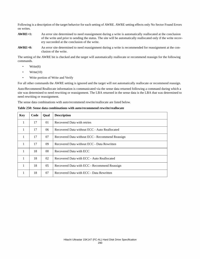
Hitachi Ultrastar 15K147 (FC-AL) Hard Disk Drive Specification290
Following is a description of the target behavior for each setting of AWRE. AWRE setting effects only No Sector Found Errors on writes.
AWRE=1: An error site determined to need reassignment during a write is automatically reallocated at the conclusion of the write and prior to sending the status. The site will be automatically reallocated only if the write recov-ery succeeded at the conclusion of the write.
AWRE=0: An error site determined to need reassignment during a write is recommended for reassignment at the con-clusion of the write.
The setting of the AWRE bit is checked and the target will automatically reallocate or recommend reassign for the following commands.
• Write(6)
• Write(10)
• Write portion of Write and Verify
For all other commands the AWRE setting is ignored and the target will not automatically reallocate or recommend reassign.
Auto/Recommend Reallocate information is communicated via the sense data returned following a command during which a site was determined to need rewriting or reassignment. The LBA returned in the sense data is the LBA that was determined to need rewriting or reassignment.
The sense data combinations with auto/recommend rewrite/reallocate are listed below.
Table 250: Sense data combinations with auto/recommend rewrite/reallocate
Key Code Qual Description
1 17 01 Recovered Data with retries
1 17 06 Recovered Data without ECC - Auto Reallocated
1 17 07 Recovered Data without ECC - Recommend Reassign
1 17 09 Recovered Data without ECC - Data Rewritten
1 18 00 Recovered Data with ECC
1 18 02 Recovered Data with ECC - Auto Reallocated
1 18 05 Recovered Data with ECC - Recommend Reassign
1 18 07 Recovered Data with ECC - Data Rewritten
Hitachi Ultrastar 15K147 (FC-AL) Hard Disk Drive Specification291
21.13 Segmented Caching
21.13.1 OverviewSegmented Caching divides the data buffer into several smaller buffers. Each buffer is used as Read/ Write/Read-Ahead buffer.
21.13.2 Read AheadThe Read Ahead function consists of reading data that the Initiator has not yet requested to the drive buffer. This function is intended to improve performance for an initiator that frequently accesses sequential data with successive SCSI read com-mands. The Read Ahead function works when RCD (the read cache disable) bit of read cache page (page 08h) is set to zero.
The drive initiates the Read ahead function when the following conditions exist:
• RCD is 0
• Read(6), Read (10), Read Verify, and Write and Verify is received
• The consecutive LBA of the requested LBA is not available in the buffer
If SCSI reset or target reset message is received, all contents of segmented buffer is flushed.
Even if an error occurs during the Read ahead, the error will not be reported to the Initiator. The data read before the error occurred will be stored as valid data by the Read Ahead function.
21.14 Multiple Initiator SystemsThis section describes how the target behaves in a multiple initiator system. Up to 32 initiators may be supported at any one time.
21.14.1 Sense DataA separate sense data area is reserved for each initiator. Each area is maintained independently. This allows a command from one initiator to complete with a CHECK CONDITION status and generate sense data without being affected by a subsequent command from a different initiator. There is no requirement for the first initiator to send a REQUEST SENSE command to retrieve the Sense Data prior to the execution of a command from a different initiator.
21.14.2 Mode PagesA single set of Mode pages is maintained. This includes both current and saved parameters. If a MODE SELECT command is executed that updates the current parameters, a unit attention condition is generated for all initiators except the one that issued the command. See 21.6.5, “Unit Attention Condition” on page 277 for more information.
21.15 Enclosure ServicesEnclosure Services allow the Host Computer System to access information held by the Enclosure Microcontroller using the same industry standard interface as the enclosed devices.
This disk drive supports the ESI (Enclosure Services Interface) for this purpose, as described in the Functional Specification.
The drive sets the EncServ bit to 1b in the Standard INQUIRY Data indicating that it supports enclosure services. This indi-cates that the Host may use the SEND DIAGNOSTIC and RECEIVE DIAGNOSTIC RESULTS commands to access informa-tion held by the Enclosure. This information is in the form of 'Diagnostic Pages'.
Diagnostic Pages 01h to 0Fh are reserved for Enclosure Services.
There are two distinct forms of Enclosure Services. The EncServ bit does not specify which form the Target and Enclosure are capable of (if any). The Host can discover this by using a RECEIVE DIAGNOSTIC RESULTS command to request Diag-notic Page 00h.
When requested to communicate with the enclosure via the SEND and RECEIVE DIAGNOSTIC commands, the drive goes
Hitachi Ultrastar 15K147 (FC-AL) Hard Disk Drive Specification292
through a 'discovery phase' with the enclosure as defined in the SFF-8067 standard. The results of this discovery phase deter-mine whether the enclosure: 1) does not support Enclosure Services, 2) supports only the 'short' Enclosure Services mode as defined by SFF-8045, or 3) supports the 'long' Enclosure Services mode as defined by SFF-8067. After the discovery phase, the drive behaves in accordance with the Enclosure Services mode capabilities of the enclosure. The drive does not attempt to remember the Enclosure Services capabilities of the enclosure, but rather, in accordance with the SFF-8067 standard, re-per-forms the discovery phase for each SEND and RECIEVE DIAGNOSTIC command received.
Note: For a more detailed description of Enclosure Services, please refer to the following specifications:
• SFF-8067 Specification
21.15.1 Enclosure Initiated ESIThis drive supports Enclosure Initiated ESI as described in the SFF-8067 standard.
21.16 Multiple Initiator Environment
21.16.1 Initiator Sense DataSeparate sense data is reserved for each I-T-L. Each sense data is maintained independent of commands from other initiators.
21.16.2 Initiator Mode Select/Mode Sense ParametersA single shared copy of the Mode Select/Mode Sense parameters is maintained by the drive. This includes both the current and saved parameters.
21.17 ResetReset actions will return the drive to a known, initialized state.
Modify the remaining sentence to read: This device supports the Hard reset option as defined in the SCSI standards (see 7.1.9 Dev_Ctrl_Code_x on page 33) and the reset sources discussed below.
Short
This mode is defined for use when an Enclosure simply supplies an 7-bit parame-ter as defined by the SFF-8045 standard to the drive.
When mounted in this type of Enclosure, an attempt to access any Enclosure Ser-vice Diagnostic Page using the SEND DIAGNOSTIC command will terminate the command with CHECK CONDITION status. The sense data will have a Sense Key of Illegal Request and an Additional Sense Code of UNSUPPORTED ENCLOSURE FUNCTION.
Requesting any Enclosure Service Diagnostic Page using the RECEIVE DIAG-NOSTIC RESULTS command will return only Diagnostic Page 08h (Short Enclo-sure Status).
Long This form is defined for use when the Enclosure and target are able to communi-cate using the secondary interface as defined in the SFF-8067 standard.
When mounted in this type of Enclosure, any attempt to access an Enclosure Ser-vice Diagnostic Page using the SEND DIAGNOSTIC or RECEIVE DIAGNOS-TIC RESULTS commands results in the Diagnostic Page being transferred to/from the enclosure. CHECK CONDITION status and sense data with an appropriate Sense Key and Additional Sense Code is generated if the transfer fails or cannot be performed.
Hitachi Ultrastar 15K147 (FC-AL) Hard Disk Drive Specification293
21.17.1 Reset SourcesThere are four sources of resets detected by the target:
21.17.2 Reset ActionsThe action taken by the drive following a reset is dependent on the source of the reset.
21.17.2.1 Power-On reset and Self-Initiated resetThese two reset conditions cause the following to be performed in the order shown:
• A power-up sequence
• A startup sequence is necessary to put the drive in a ready stateThese reset conditions cause the following actions:
• If the reset occurs during the power-up sequence, the power-up sequence is re-started.
• If the auto-start option is enabled and a start-up sequence has not yet completed, the start-up sequence is restarted. Note: The power-up sequence is not re-run, since it has already completed.
• If the reset occurs while a physical sector is being written, the WRITE operation is disabled at the end of the current sector. The media is not corrupted if power is maintained to the end of the current sector.
21.18 DiagnosticsThe drive will execute Power on Diagnostics at power on time to assure the correct operation of the drive by validating com-ponents (ROM, RAM, Sector Buffer, EEPROM, HDC, Spindle Motor, Actuator), checking stored information in the Reserved Area and EEPROM, and verifying fault detects circuits.
Self-test can be invoked by issuing a SEND DIAGNOSTIC command.
21.18.1 Power on DiagnosticsAt power on time the following tests are executed:
1. Validation of ROM and EEPROM2. RAM test for internal RAM3. Test and Initialize HDC registers4. RAM test for Sector Buffer5. Start Spindle Motor (if Auto spin up enable)
Reset Name Reset Source
Power-On Reset This is the signal generated by the hardware at initial power-on
Self-Initiated reset This is a software-generated reset that occurs when a catastrophic error is detected by the microcode.
LIP Reset This is a LIP(AL_PS_PD) primitive sequence where the AL_PD matches the AL_PA of the drive.
Target Reset This is an FCP_CMD IU with the TARGET RESET TMF flag set.
Reset LUN This is a FCP_CMD IU with the RESET LUN TMF flag set.
Hitachi Ultrastar 15K147 (FC-AL) Hard Disk Drive Specification294
6. Calibration of Actuator7. Read/Write test for all Heads8. Validation of RAM code and data table (RDM, Log, Mode Page) from the Reserved Area
If Auto spin up is disabled, steps 5 - 8 will be executed by the first START STOP UNIT command which has the Start bit set.
Faults detected before successful completion of the HDC section could prevent the drive from responding to a selection.
Faults detected after the successful completion of the HDC test section will be reported as CHECK CONDITION status to the Initiator on the first command issued after a fault is detected (except for the INQUIRY, REPORT LUNS and REQUEST SENSE commands). The INQUIRY, REPORT LUNS and REQUEST SENSE commands will always be responded with a GOOD status. Detecting a fault during power on will not terminate execution of the tests nor will it terminate the power on process.
21.18.2 Self-test via SEND DIAGNOSTIC Command
21.18.2.1 Default Self-testThe default self-test is invoked by the SlfTst bit in the SEND DIAGNOSTIC command. The response is simply a GOOD sta-tus if the test is successful or a CHECK CONDITION status if the test fails.
The following tests are performed by the default self-test (in the order defined):
1. Spin check is to check if the spindle motor is running at the correct speed.2. Write, Read and Compare test is a disk read/write test. It writes data to a predefined location in the reserved area and
then reads it back and validates the content. All heads are tested. 3. ECC circuit test is a test for ECC circuit to ensure that errors can be corrected by the circuit.4. Seek test is a servo test. It validates seeks to 256 random locations out of the full volume.
21.18.2.2 Short and Extended Self-testsThere are two other types of self-tests that may be invoked using the Function Code field in the SEND DIAGNOSTIC com-mand: a short self-test and an extended self-test. The tests performed in the short and extended self-tests are described later. The time required by a logical unit to complete its extended self- test is specified in the Extended self-test Completion Time field in the Control Mode Page. The results of self-test can be retrieved via the LOG SENSE command for Log Page 10.
21.18.2.3 Self-test ModesThere are two modes for short and extended self-tests: a foreground mode and a background mode. These modes are described in the following clauses.
Foreground mode
When the drive receives a SEND DIAGNOSTIC command specifying a self-test to be performed in the foreground mode, the drive will return status for that command after the self-test has been completed. While performing a self-test in the foreground mode, the drive will respond to all commands except INQUIRY, REPORT LUNS, and REQUEST SENSE with a CHECK CONDITION status, a sense key of NOT READY and an additional sense code of LOGICAL UNIT NOT READY - SELF-TEST IN PROGRESS.
If the drive is performing a self-test in the foreground mode and a test error occurs, the drive will update the self-test results log page and report CHECK CONDITION status with a sense key of HARDWARE ERROR and an additional sense code of LOGICAL UNIT FAILED SELF-TEST. The application client may obtain additional information about the failure by reading the self-test results log page.
An application client may terminate a self-test that is being performed in the foreground mode using an ABORT TASK, ABORT TASK SET, or CLEAR TASK SET task management function. If the drive receives an ABORT TASK, ABORT TASK SET, or CLEAR TASK SET task management function while performing a self-test in the foreground mode, it will abort the self-test and update the self-test results log page.
Background mode
Hitachi Ultrastar 15K147 (FC-AL) Hard Disk Drive Specification295
When the drive receives a SEND DIAGNOSTIC command specifying a self-test to be performed in the background mode, the drive will return status for that command as soon as the command descriptor block has been validated. After returning status for the SEND DIAGNOSTIC command specifying a self- test to be performed in the background mode, the drive will initial-ize the self-test results log page as follows. The Function Code from the SEND DIAGNOSTIC command will be placed in the Function Code field in the log page. The self-test Results field shall be set to 0Fh. After the self-test results log page is initial-ized, the drive will begin the first self-test segment.
While the device server is performing a self-test in the background mode, it shall terminate with a CHECK CONDITION sta-tus any SEND DIAGNOSTIC command it receives that meets one of the following criteria:
a. The SlfTst bit is oneb. The Function Code field contains a value other than 000b or 100b.
When terminating the SEND DIAGNOSTIC command, the sense key shall be set to NOT READY and the additional sense While performing a self-test in the background mode, the drive will suspend the self- test to service any other command other than SEND DIAGNOSTIC (with Function Code field set to 100b) WRITE BUFFER (with the mode set to any download microcode option), FORMAT UNIT and START UNIT STOP command. Suspension of the self-test to service the command will occur within 2 seconds. If SEND DIAGNOSTIC (with Function Code field set to 100b), WRITE BUFFER (with the mode set to any download microcode option), FORMAT UNIT or START UNIT STOP command is received, the drive will abort the self-test, update the self-test log, and service the command within two seconds after the command descriptor block has been validated.
An application client may terminate a self-test that is being performed in the background mode by issuing a SEND DIAG-NOSTIC command with the Function Code field set to 100b (Abort background self-test function).
Elements common to foreground and background self-test modes
The Progress Indication field returned in response to a REQUEST SENSE command may be used by the application client at any time during execution of a self-test to poll the progress of the test. While executing a self-test unless an error has occurred, the drive will respond to a REQUEST SENSE command by returning a sense key of NOT READY and an additional sense code of LOGICAL UNIT NOT READY - SELF-TEST IN PROGRESS with the sense key specific bytes set for progress indi-cation.
The application client may obtain information about the twenty most recently completed self-tests by reading the self-test results log page. This is the only method for an application client to obtain information about self-tests performed in the back-ground mode. The default self-test results are not logged in the log page.
Tests performed in the Short and Extended Self-test
The following table defines the tests performed in the short and extended self test. They are defined by their segment number which is also used to report Self-Test Results, in Log Sense Page 10. Note that the only difference between the Short and the Extended tests, is the sequential verify test in segment 9h. Also note that either of these tests can be run in foreground or back-
Hitachi Ultrastar 15K147 (FC-AL) Hard Disk Drive Specification296
ground mode as previously described.
Table 251: Short and Extended Self-Test Description
21.18.2.4 Background Medium ScanFor a related function, see Mode Page 1C (Informational Exceptions Control), page 192
Segment
Number
Short Self-Test
Extended Self-Test
Test Description
1h Drive Ready Test Internal check to insure drive is “ready”, similar to a Test Unit Ready command.
2h Drive Diagnostics This test is comprised of the Default Self Test as defined in Section 21.18.2.1, “Default Self-test” on page 294
3h SMART Perform SMART testing and check results to ensure that SMART threshold criteria are not exceeded
4h Low Level Format check Check to insure that the media is currently not in the MEDIA FORMAT CORRUPTED state.
5h Physical Head Check Write/Read test on each head in a predefined location in the drive's Reserved Area of the disk.
6h Random Verify Perform 4000 random verify operations and insure no uncorrectable errors.
7h - Verify First 300MB
- Verify Last 100 MB
Verify all LBA’s
Sequential verify operation. Ensure that no uncorrect-able errors occur within the verify range.
8h Recheck SMART Same as segment 3h.
Hitachi Ultrastar 15K147 (FC-AL) Hard Disk Drive Specification297
21.19 Idle Time FunctionThe drive periodically saves data in logs and PFA counters in the reserved area of the disks. The information is used by the drive to support various SCSI commands and for the purpose of failure analysis. This is performed if the drive has not received a SCSI command for 10 minutes.
21.20 Command Time out Limits The 'Command Time-out Limits' are defined as the time period from the SCSI Arbitration phase through the SCSI Task com-plete message, associated with a particular command.
The following times are for environments where Automatic Reallocation is disabled and there are no queued commands.
21.20.1 Reassignment TimeThe drive should be allowed a minimum of 5 seconds to complete a “Reassign Blocks” command.
21.20.2 Format TimeApproximately 60 minutes should be allowed to complete a "Format Unit" command when certification is disabled. Allow 120 minutes when certification is enabled. If "Fast Format" is enabled via the FFMT bit in mode page 00h, allow 30 seconds for completion."
21.20.3 Start/Unit Stop TimeThe drive should be allowed a minimum of 30 seconds to complete a “Start Stop Unit” command (with Immed bit = 0). Initia-tors should also use this time to allow startup sequences initiated by auto start ups and “Start Stop Unit” commands (with Immed bit = 1) to complete and place the drive in a “ready for use” state.
Note: A time-out of one minute or more is recommended but NOT required. The larger system time-out limit allows the system to take advantage of the extensive ERP/DRP that the drive may attempt in order to successfully complete the startup sequence.
Hitachi Ultrastar 15K147 (FC-AL) Hard Disk Drive Specification298
21.20.4 Medium Access Command TimeThe time-out limit for medium access commands that transfer user data or non-user data or both should be a minimum of 30 seconds. These commands are
Pre-Fetch
Read
Read Defect Data
Seek
Send Diagnostic (Function Code = 0)
Read Long
Reassign Blocks
Write
Write and Verify
Write Buffer
Write Same
Verify
Note: The 30-second limit assumes the absence of bus contention and data transfers of 64 blocks or less. This time should be adjusted for anticipated bus contention and if longer user data transfers are requested.
21.20.5 Time-out Limits for Other CommandsThe drive should be allowed a minimum of 5 seconds to complete these commands:
Inquiry
Log Select
Log Sense
Mode Select
Mode Sense
Persistent Reserve In/Out
Read Buffer
Read Capacity
Read Long
Release
Request Sense
Reserve
Set/Report Device Identifier
Start/Stop Unit (with Immed bit = 1)
Synchronize Cache
Test Unit Ready
Writer Long
The command time-out for a command that is not located at the head of the command queue should be increased by the sum of command time-outs for all of the commands that are performed before it is.
Hitachi Ultrastar 15K147 (FC-AL) Hard Disk Drive Specification299
21.21 Recommended Initiator ERPThe Drive's design points for error reporting to the system assumes certain system action for the error return codes. These assumptions are:
1. SCSI protocol will be the first priority in reporting errors.2. The system will maintain a log of all reported errors.3. System architecture should include all error handling recommendations made in this section. Deviations should have
mutual agreement between Drive development and system integration.
This section is directed toward documenting the assumptions made by the Drive that the system is expected to implement. The two error classes that the system should be concerned with are DATA and NON-DATA errors.
Data errors are those errors that deal with the handling of data to and from the MEDIA and are identified by the Additional Sense Code contained in the sense data. The Additional Sense Codes for data errors are as follows:
• OC - Write error
• 11 - Unrecovered read error
• 14 - No record found
• 16 - Data Synchronization mark error
• 17 - Recovered read error without ECC correction
• 18 - Recovered read error with ECC correction
Typically, data errors do not include positioning of the heads or the data path though the electronics.
Nondata errors are those errors that do not have a direct relationship with transferring data to and from the media. Nondata errors can include data handling if the media is not associated with the error (that is, interface error).
The system action assumed for each class of error is outlined here.
21.21.1 Drive Service StrategyThe Drive service strategy is defined so the customer will be able to use the system as soon after a failure is detected as possi-ble. The first priority is to replace the entire drive to make the system operational with minimal service time. The service rep-resentative should:
1. Back up all the customer data on this drive if possible2. Replace the complete drive3. Restore the customer data4. Return the drive to customer service
Hitachi Ultrastar 15K147 (FC-AL) Hard Disk Drive Specification300
21.21.2 Recommendations for System Error LogThe system error log should contain information about the Drive error that will allow recovery actions. The system error logs should contain all the error information returned in the sense data. At a minimum, the following information about each error occurrence should be logged.
• Valid bit and error code (Sense byte 0)
• Sense Key (Sense byte 2)
• Information bytes (Sense bytes 3 through 6)
• Command specific information (Sense bytes 8 through 11)
• Additional Sense Code (Sense byte 12)
• Additional Sense Code Qualifier (Sense byte 13)
• Field Replaceable Unit (Sense byte 14)
• Sense Key Specific (Sense bytes 15, 16, and 17)
• Vender Unique error information (Sense bytes 20 through 23)
21.21.3 Data Recovery ProcedureStatistically, most data error activity is noise related and has nothing to do with defects in the media. It is wrong for the system to assume that every data error reported occurred because of a defect in the media. It is also wrong for the system to assume that every data error that occurred because of a media defect rendered the Drive unusable.
Recurring data error activity at the same physical location is an indication of a problem. The problem can be due to a media defect or magnetic damage. A media defect is physical damage to the recording capability of the media while magnetic dam-age is a defect in the bit pattern written to the media.
In both cases, the error can be corrected without replacing the unit. The physical sector may require relocation. The Drive determines the need to reassign a sector. The Mode Select Page 1 option bit ARRE (See Section 19.10.3, “Mode Page 01 (Read/Write Error Recovery Parameters)” on page 173) set active allows the Drive to relocate recovered read data errors. Non recovered data errors or the ARRE bit being inactive will have additional sense codes returned to recommend reassignment of sectors.
The need to reassign a sector should be infrequent. Sites not meeting error rate criteria are removed from use during SAT (Sur-face Analysis Test) in Drive manufacturing. With the exception of some early life SAT escapes (sites that were marginally missed during SAT), reassigning defective sectors should be rare. Frequent sector reassignment may be an (early) indication of another type of failure. Sector reassignments are monitored as part of the predictive failure analysis. When a threshold is exceeded, the Drive will notify the initiator that a scheduled service action is required.
Drive soft error rates are based on extraneous random faults that are not predictable. Media defects discovered after the Drive completes manufacturing final test need to be relocated so that soft error rates are not influenced by predictable known error sites. Failure of the system to properly relocate defective media sites can have a direct influence on system throughput and drive error rates.
Hitachi Ultrastar 15K147 (FC-AL) Hard Disk Drive Specification301
21.21.3.1 Reassign a Physical SectorThe Drive determines the need to reassign physical sectors based on error activity. Once a physical sector requires reassign-ment, the Drive will either reassign the physical sector, or recommend to the initiator that the LBA associated with the physical sector be reassigned.
When the following Sense Key, Additional Sense Code, and Additional Sense Code Qualifier combinations are returned, the initiator should reassign the LBA reported at the next opportunity.
Note: In Table 252, the Key, Code, and Qualifier fields are all hex values (i.e., Sense Key 1 is 1h, Sense Code 17 is 17h, etc.).
Table 252: Recommend Reassign Errors
To reassign an LBA that has sense data recommending a reassignment, the initiator should:
1. Attempt to recover the data from the sector being reassigned with a Read (08) or Read (28) command.2. Reassign the LBA using the Reassign Blocks (07) command.
- If the reassignment completes successfully (Good Status), log the error in the system error log.
- If the reassignment completes unsuccessfully (Check Condition Status), follow the procedure in Section 21.21.3.3, “Reassign Blocks Recovery” on page 302.
3. Write the LBA that was reassigned.
21.21.3.2 Data Error LoggingThe Drive will report data errors to the initiator that do not require immediate action (successful auto reallocation, successful auto rewrite, or no action needed on this occurrence). The initiator should log these errors in the system error log. No other action is required.
Table 253: Log Only Errors
Key Code Qual Description
1 17 07 Recovered Data without ECC - Recommend Reassignment
1 18 05 Recovered Data with ECC - Recommend Reassignment
Key Code Qual Description
1 16 00 Data Synchronization Mark Error
1 17 01 Recovered Data with Retries
1 17 06 Recovered Data without ECC - Auto Reallocated
1 17 09 Recovered Data without ECC - Data Rewritten
1 18 00 Recovered Data with ECC
1 18 02 Recovered Data with ECC - Auto Reallocated
1 18 07 Recovered Data with ECC - Data Rewritten
Hitachi Ultrastar 15K147 (FC-AL) Hard Disk Drive Specification302
21.21.3.3 Reassign Blocks RecoveryThe Drive provides the capability to remove media defects without reducing capacity. If the mode parameter bit ARRE is active, the Drive will automatically reallocate LBA's determined to be defective. For those LBA's where the error is unrecov-erable or the initiator elects to not have the Drive automatically reallocate LBA's, the Drive will recommend reassignment of the LBA.
Recovery from a failed reassignment consists of the following actions:
• Updating the defect descriptor to remove the LBA's that have been successfully reassigned and then retry the Reas-sign Blocks command. The LBA contained in the Command Specific Information field of the Sense Data is the LBA in the first defect descriptor that was not reassigned because of the failure. If the command failed because of an unre-coverable read error other than those specified in the defect descriptor, add this LBA to the defect descriptor and retry the command. Refer to Section 19.23, “REASSIGN BLOCKS (07)” on page 222, for additional information.
• If the retried Reassign Blocks (07) command completes successfully, returning to normal processing.
• If the retried Reassign Blocks (07) command fails, servicing the drive using the service guidelines recommended in Section 21.21.1, “Drive Service Strategy” on page 299.
21.21.4 Nondata Error Recovery ProcedureThe Drive will follow a logical recovery procedure for nondata errors. The initiator options for non-data errors are limited to logging the error, retrying the failing command, or replacing the drive.
These recovery procedures assume the initiator practices data back-up and logs errors at the system level for interrogation by service personnel.
21.21.4.1 Drive BusyThe Drive is busy performing an operation. This is not an error condition. The initiator can test for completion of the opera-tion by issuing Test Unit Ready (00) (or media access) commands.
• If the Test Unit Ready (00) (or media access) command completes with Check Condition Status then issue a Request Sense (03)
- If the specified recovery procedure for the sense data is for a condition other than drive busy, follow the recovery procedure for the condition reported.
- If the specified recovery procedure for the sense data is for a drive busy condition, then continue re-issuing the Test Unit Ready (00) and Request Sense commands for the duration of a media access time-out or until the drive returns Good Status.
- If the drive has been busy for longer than the limit specified in Section 21.20, “Command Time out Limits” on page 297, then service the drive using the service guidelines recommended in Section 21.21.1, “Drive Service Strategy” on page 299. Otherwise return to normal processing.
• If the Test Unit Ready (00) (or media access) command completes with Good Status, then return to normal process-ing.
21.21.4.2 Unrecovered Drive ErrorThe initiator should retry the failing command.
1. If the retry of the failing command completes with Good Status or recovered Sense Key, follow the recovery procedure in Section 21.21.4.3, “Recovered Drive Error” on page 303.
2. If the retry of the failing command completes with hardware error sense, verify there is no outside cause (e.g., power supply) for the failure, then retry the failing command. a. If the retry of the failing command completes with Good Status, follow the recovery procedure in next Section
21.21.4.3, “Recovered Drive Error” on page 303.b. If the retry of the failing command completes with Recovered sense or Hardware error sense, then service the drive
using the service guideline recommended in Section 21.21.1, “Drive Service Strategy” on page 299.
Hitachi Ultrastar 15K147 (FC-AL) Hard Disk Drive Specification303
21.21.4.3 Recovered Drive ErrorThe Initiator should log the error as soft with the recovery level.
21.21.4.4 Drive Not ReadyThe initiator should do the following:
1. Issue a Start Stop Unit (1B) command.2. Verify that the drive comes ready within the time specified in Section 4.5.2, “Drive ready time” on page 13.3. If the drive fails to come ready within the specified time, service the drive using the service guidelines specified in Sec-tion 21.21.1, “Drive Service Strategy” on page 299.
4. Retry the failing command. a. If the failing command completes with Good Status, log the error as recovered.b. If the failing command completes with Not Ready sense, verify there is no outside cause (for example, the power
supply). Then service the drive using the service guidelines specified in Section 21.21.1, “Drive Service Strategy” on page 299.
21.21.4.5 No Defect SpareThree conditions can cause this error:
1. When the Reassign Blocks (07) command is issued and there are no spares available for the Drive to use for the reloca-tion requested.
2. When the Glist is full and the sector to be reassigned cannot be added.3. During a format operation, there was not enough space available to fulfill the spare requirement (Dlist is too large).
Service the Drive following Section 21.21.1, “Drive Service Strategy” on page 299.
21.21.4.6 Degraded ModeRefer to Section 21.6.9, “Degraded Mode” on page 280, for the definition of this state. There are three causes for entering degraded mode. In all cases the Sense Key is Not Ready. The causes are the following:
1. Sense Code/Qualifier of Logical Unit Not Ready, initializing command required. The spindle motor not spinning or not at the proper speed. This may not be an error condition. The initiator should issue a Unit start (1B) command to start the spindle motor. If the Drive fails to come ready in the time specified in Section 21.20, “Command Time out Limits” on page 297, service the drive using the service guideline recommended in Section 21.21.1, “Drive Service Strategy” on page 299.
2. Sense Code/Qualifier of Diagnostic Failure. Failure of a Send Diagnostic self test, a start up sequence, or other internal target failures.
- Failure of a send diagnostic self test or a start up sequence.
This failure is the result of the diagnostics that are executed during power on or when the Send Diagnostic (1D) com-mand is executed detecting a failure. As with the RAM code not loaded and the configuration data not loaded, the recovery is either a power cycle or issuing the Send Diagnostic (1D) command with the self test bit set active.Recovery for a failed Send Diagnostic (1D) is achieved in one of the following ways:
Executing the Send Diagnostic (1D) command
Power cycling the drive
If the failure repeats, service the drive using the service guideline recommended in Section 21.21.1, “Drive Service Strategy” on page 299.
Recovery for a failed power up sequence is achieved in one of the following ways:
Issuing a Unit start (1B) command
Power cycling the drive.
If the failure repeats, service the drive using the service guideline recommended in Section 21.21.1, “Drive Service Strategy” on page 299.
Hitachi Ultrastar 15K147 (FC-AL) Hard Disk Drive Specification304
- Internal target failures
The drive periodically adjusts the track following for each head to compensate for expansion and contraction of the disks due to temperature changes. If one of these adjustments fails, the drive will enter a degraded mode to prevent writing data off track.
Recovery of this condition is either a power cycle or successful completion of the Send Diagnostic (1D). Service the drive using the recommended service guidelines specified in Section 21.21.1, “Drive Service Strategy” on page 299, if the power cycle or the Send Diagnostic (1D) command fail to complete successfully.
3. Sense Code/Qualifier of Format Command Failed Format Unit (04), Sense Code/Qualifier of Medium Format Cor-rupted Reassign Failed Reassign Blocks (07) command, or an automatic reallocation failed or was abnormally termi-nated.
Recovery from a failed Format Unit (04) is achieved by retrying the command. If the command fails a second time, ser-vice the drive following the procedure defined in Section 21.21.1, “Drive Service Strategy” on page 299.
If the above defined recovery procedures fail to clear the degraded mode condition, the Drive should be replaced. Follow the procedure in Section 21.21.1, “Drive Service Strategy” on page 299, when replacing the drive.
21.21.4.7 Reserved Area Hard ErrorSectors found defective in the reserved area of the disk cannot be reassigned after the Drive leaves the factory. The data in the reserved area is not directly accessible by the initiator. For this reason, the reserved area has all data. A data error must occur in both copies of the data record before the Drive considers a reserved area read error. When this happens, the integrity of the drive is questionable.
Service the Drive using Section 21.21.1, “Drive Service Strategy” on page 299.
21.21.4.8 Interface ProtocolFor all interface protocol errors, the initiator should complete the following steps:
1. Correct the parameter that caused the Illegal Request2. Retry the failing command3. If the first retry of the failing command completes with
- Good Status, log the error as recovered
- Check Condition Status with sense data for an Illegal Request, verify there is no outside cause (for example, the power supply) for the failure
- Other, follow the recommendations for the error condition reported. Retry the failing command. If this retry of the failing command completes with
• Good Status, log the error as recovered
• Check Condition Status with sense data for an Illegal Request, service the drive using the service guideline rec-ommended in Section 21.21.1, “Drive Service Strategy” on page 299.
• Other, follow the recommendations for the error condition reported.
21.21.4.9 Aborted CommandThe initiator should determine the cause from the Additional Sense Code (byte 12):
• Sense Key = B (Aborted Command) with Additional Sense Codes of 1B, 25, 43, 49, and 4E are initiator caused abort conditions. The initiator should correct the condition that caused the abort and retry the failing command.
• Sense Key = B (Aborted Command) with Additional Sense Code of 44 or 48 are drive caused abort conditions. The initiator should:1. Retry the failing command.2. If the retry of the failing command completes with
Hitachi Ultrastar 15K147 (FC-AL) Hard Disk Drive Specification305
- Good Status, log the error as recovered.
- Abort Command Sense, verify there is no outside cause (e.g. power supply) for the failure.3. Retry the failing command.4. If the retry of the failing command completes with
- Good Status, log the error as recovered.
- Abort command sense, then service the drive using the service guideline recommended in Section 21.21.1, “Drive Service Strategy” on page 299.
• Sense Key = B (Aborted Command) and an Additional Sense Code of 47 can be an initiator or Drive caused abort condition. The initiator should follow the above procedure for initiator caused abort conditions if the Drive detected the SCSI bus parity error. The initiator should follow the above procedure for Drive caused abort conditions if the ini-tiator detected the SCSI bus parity error.
21.21.4.10 Unit Attention ConditionUnit Attention Conditions are not errors. They alert the initiator that the drive had an action that may have changed an initiator controlled state in the drive. These conditions are the following:
Not Ready to Ready Transition
Not ready to ready transition, unit formatted. This Unit Attention Condition will not be reported to the initiator that issued the Format Unit (04).
Reset
Reset - This means the drive was reset by either a power-on reset, LIP Reset, Target Reset or an internal reset.
Mode Parameters Changed
A Mode Select (15) command successfully completed. This means that the mode parameters that are the current value may have changed. The parameters may or may not have changed but the command to change the parameters successfully com-pleted. The Drive does not actually compare the old current and the new current parameters to determine if the parameters changed. This Unit Attention Condition will not be reported to the initiator that issued the Mode Select (15).
Microcode Has Changed
Write Buffer (3B) to download microcode has successfully completed. This means that the microcode that controls the Drive has been changed. The code may or may not be the same as the code currently being executed. The Drive does not compare old level code with new code.
Commands Cleared by Another Initiator
Tagged commands cleared by a clear queue message. This means that the command queue has been cleared. The Unit Atten-tion Condition is not reported to the initiator that issued the clear queue message. Unit Attention Condition is reported to all initiators that had commands active or queued.
Reissue any outstanding command.
Log Select Parameters Changed
A Log Select (4C) command successfully completed. This means that the Log Select command cleared statistical information successfully (See Section 19.6, “LOG SELECT (4C)” on page 136). Unit Attention Condition is reported to all initiators excluding the initiator that issued the Log Select command.
Device Identifier Changed
A Set Device Identifier (A4) command successfully completed. This means that the Set Device Identifier information field has been updated. (See 19.38, “SET DEVICE IDENTIFIER (A4/06)” on page 248) A Unit Attention Condition is reported to all initiators excluding the initiator that issued the Set Device Identifier command.
Hitachi Ultrastar 15K147 (FC-AL) Hard Disk Drive Specification306
21.21.4.11 Components MismatchThe compatibility test is performed at a power cycle. The compatibility test verifies the microcode version of the electronics. When the Drive detects the microcode version mismatch, the most likely cause is the result of incorrect parts used during a ser-vice action.
If the error reported is Key/code/qualifier 4/40/80, Diagnostic failure, bring-up fail, the initiator should do the following:
1. Retry Power cycle
2. Check the send diagnostic end status. If the status is
- GOOD, Return to normal processing
- Check Condition Status, issue a Request Sense (03) and follow the recommendations for the sense data returned unless the sense data is for a component mismatch. If the sense data is for component mismatch, service the drive using the service guideline recommended in Section 21.21.1, “Drive Service Strategy” on page 299.
21.21.4.12 Self Initiated ResetThe Drive will initiate a self reset when the condition of the Drive cannot be determined. The internal reset will terminate any outstanding commands, release any reserved initiators, and stop the spindle motor. The initiator can recover by
1. Logging the error
2. Retrying the failing command. If the failing command completes with:
- Good Status, return to normal processing
- Self initiated reset sense, service the drive according the guidelines recommended in Section 21.21.1, “Drive Ser-vice Strategy” on page 299.
- Other, follow the recommendations for the error reported.
21.21.4.13 Defect List RecoveryThis is not an error condition.
The initiator either requested a defect list in a format (block or vendor specific) that the Drive does not support or the requested defect list(s) exceed the maximum list length that can be returned. If the Sense Key/Code/Qualifier are:
1/1F/00, the requested list(s) exceed the maximum length that can be supported. The initiator should request one list at a time. If a single list exceeds the maximum returnable length, this may be an indication of a marginally operational drive. Service the drive following the service guidelines in Section 21.21.1, “Drive Service Strategy” on page 299.
1/1C/01 or 1/1C/02, the requested defect list is not in the format that the Drive supports. The requested defect list is returned in the physical (cylinder, sector, head) format. This is the default format. There is no initiator action required for this condition.
Hitachi Ultrastar 15K147 (FC-AL) Hard Disk Drive Specification307
21.21.4.14 Miscompare RecoveryA miscompare can occur on a Verify (2F) command or a Write and Verify (2E) with the byte check (BytChk) bit active. Recov-ery for a miscompare error is different for the two commands.
Verify Command
The initiator should do the following:
1. Verify that the data sent to the drive is the correct data for the byte-by-byte compare.
2. Read the data from the media with a Read (08) or Read (28) command and verify that the data from the media is the expected data for the byte-by-byte compare.
- If all data are correct, this is an indication that the data may have been read from the media incorrectly without an error detected. Service the drive using the procedure specified in Section 21.21.1, “Drive Service Strategy” on page 299.
- If all data are not correct, this is an indication that the data on the media is not the data the initiator expected. Rewrite the correct data to the media.
Write and Verify Command
The drive uses the same data in the data buffer to write then read and compare. A miscompare error on the Write and Verify (2E) command is an indication that the drive cannot reliably write or read the media. Service the drive using the procedures specified in Section 21.21.1, “Drive Service Strategy” on page 299.
21.21.4.15 Microcode ErrorThe microcode from the interface is validated before the device operates using that microcode. When the validation detects incorrect or incomplete data, the Drive enters degraded mode.
If the initiator attempted to load microcode using the Write Buffer (3B) retry the Write Buffer (3B). If the command completes with
• Good Status - return to normal processing
• Check Condition Status - service the drive using the service guidelines recommended in Section 21.21.1, “Drive Ser-vice Strategy” on page 299.
If the check sum error occurred during normal processing, the initiator may attempt to load microcode before deciding to ser-vice the drive using the service guidelines recommended in Section 21.21.1, “Drive Service Strategy” on page 299.
To load new microcode, the initiator should issue a Write Buffer (3B) command with the download and save option. If the Write Buffer (3B) command completes with
• Good Status, return to normal processing. Retry the failing command. If the task complete with
- Good Status - Continue normal processing.
- Check Condition Status for check sum error - Service the drive using the service guidelines recommended in Sec-tion 21.21.1, “Drive Service Strategy” on page 299.
- Check Condition Status for any other error - follow the recommended recovery procedure for the error reported.
• Check Condition Status for Check sum error, service the drive using the service guidelines recommended in Section 21.21.1, “Drive Service Strategy” on page 299.
• Check Condition Status for any other error, follow the recommendations for the returned sense data.
Hitachi Ultrastar 15K147 (FC-AL) Hard Disk Drive Specification308
21.21.4.16 Predictive Failure AnalysisThe Drive performs error log analysis and will alert the initiator of a potential failure. The initiator should determine if this device is the only device with error activity.
If this drive is the only drive attached to the initiator with error activity, service the drive using the procedures specified in Sec-tion 21.21.1, “Drive Service Strategy” on page 299.
Note: Service for this drive can be deferred. The longer service is deferred, the more probable a failure can occur that will require immediate service.
If more than this drive is experiencing error activity, the drive is probably not at fault. Locate and service the outside source causing error activity on this drive.
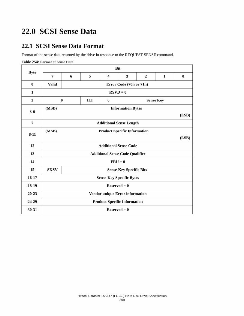
Hitachi Ultrastar 15K147 (FC-AL) Hard Disk Drive Specification309
22.0 SCSI Sense Data
22.1 SCSI Sense Data FormatFormat of the sense data returned by the drive in response to the REQUEST SENSE command.
Table 254: Format of Sense Data.
ByteBit
7 6 5 4 3 2 1 0
0 Valid Error Code (70h or 71h)
1 RSVD = 0
2 0 ILI 0 Sense Key
3-6(MSB) Information Bytes
(LSB)
7 Additional Sense Length
8-11(MSB) Product Specific Information
(LSB)
12 Additional Sense Code
13 Additional Sense Code Qualifier
14 FRU = 0
15 SKSV Sense-Key Specific Bits
16-17 Sense-Key Specific Bytes
18-19 Reserved = 0
20-23 Vendor unique Error information
24-29 Product Specific Information
30-31 Reserved = 0
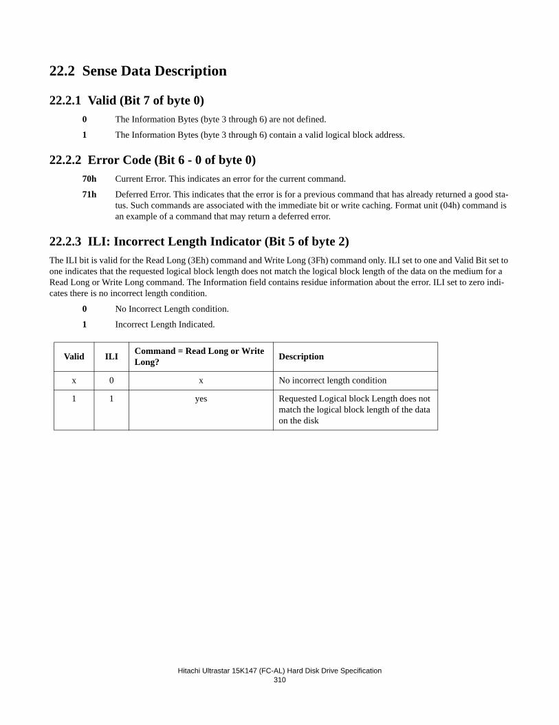
Hitachi Ultrastar 15K147 (FC-AL) Hard Disk Drive Specification310
22.2 Sense Data Description
22.2.1 Valid (Bit 7 of byte 0)0 The Information Bytes (byte 3 through 6) are not defined.
1 The Information Bytes (byte 3 through 6) contain a valid logical block address.
22.2.2 Error Code (Bit 6 - 0 of byte 0)70h Current Error. This indicates an error for the current command.
71h Deferred Error. This indicates that the error is for a previous command that has already returned a good sta-tus. Such commands are associated with the immediate bit or write caching. Format unit (04h) command is an example of a command that may return a deferred error.
22.2.3 ILI: Incorrect Length Indicator (Bit 5 of byte 2)The ILI bit is valid for the Read Long (3Eh) command and Write Long (3Fh) command only. ILI set to one and Valid Bit set to one indicates that the requested logical block length does not match the logical block length of the data on the medium for a Read Long or Write Long command. The Information field contains residue information about the error. ILI set to zero indi-cates there is no incorrect length condition.
0 No Incorrect Length condition.
1 Incorrect Length Indicated.
Valid ILI Command = Read Long or Write Long? Description
x 0 x No incorrect length condition
1 1 yes Requested Logical block Length does not match the logical block length of the data on the disk
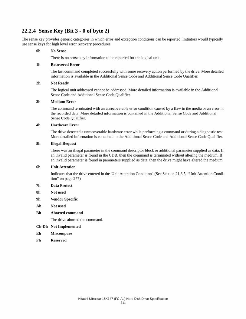
Hitachi Ultrastar 15K147 (FC-AL) Hard Disk Drive Specification311
22.2.4 Sense Key (Bit 3 - 0 of byte 2)The sense key provides generic categories in which error and exception conditions can be reported. Initiators would typically use sense keys for high level error recovery procedures.
0h No Sense
There is no sense key information to be reported for the logical unit.
1h Recovered Error
The last command completed successfully with some recovery action performed by the drive. More detailed information is available in the Additional Sense Code and Additional Sense Code Qualifier.
2h Not Ready
The logical unit addressed cannot be addressed. More detailed information is available in the Additional Sense Code and Additional Sense Code Qualifier.
3h Medium Error
The command terminated with an unrecoverable error condition caused by a flaw in the media or an error in the recorded data. More detailed information is contained in the Additional Sense Code and Additional Sense Code Qualifier.
4h Hardware Error
The drive detected a unrecoverable hardware error while performing a command or during a diagnostic test. More detailed information is contained in the Additional Sense Code and Additional Sense Code Qualifier.
5h Illegal Request
There was an illegal parameter in the command descriptor block or additional parameter supplied as data. If an invalid parameter is found in the CDB, then the command is terminated without altering the medium. If an invalid parameter is found in parameters supplied as data, then the drive might have altered the medium.
6h Unit Attention
Indicates that the drive entered in the 'Unit Attention Condition'. (See Section 21.6.5, “Unit Attention Condi-tion” on page 277)
7h Data Protect
8h Not used
9h Vendor Specific
Ah Not used
Bh Aborted command
The drive aborted the command.
Ch-Dh Not Implemented
Eh Miscompare
Fh Reserved
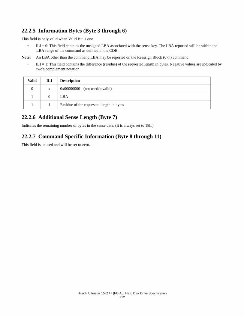
Hitachi Ultrastar 15K147 (FC-AL) Hard Disk Drive Specification312
22.2.5 Information Bytes (Byte 3 through 6)This field is only valid when Valid Bit is one.
• ILI = 0: This field contains the unsigned LBA associated with the sense key. The LBA reported will be within the LBA range of the command as defined in the CDB.
Note: An LBA other than the command LBA may be reported on the Reassign Block (07h) command.
• ILI = 1: This field contains the difference (residue) of the requested length in bytes. Negative values are indicated by two's complement notation.
22.2.6 Additional Sense Length (Byte 7)Indicates the remaining number of bytes in the sense data. (It is always set to 18h.)
22.2.7 Command Specific Information (Byte 8 through 11)This field is unused and will be set to zero.
Valid ILI Description
0 x 0x00000000 - (not used/invalid)
1 0 LBA
1 1 Residue of the requested length in bytes
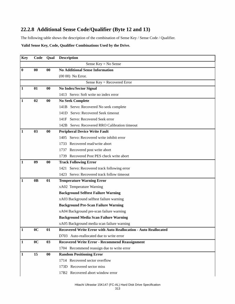
Hitachi Ultrastar 15K147 (FC-AL) Hard Disk Drive Specification313
22.2.8 Additional Sense Code/Qualifier (Byte 12 and 13)The following table shows the description of the combination of Sense Key / Sense Code / Qualifier.
Valid Sense Key, Code, Qualifier Combinations Used by the Drive.
Key Code Qual Description Sense Key = No Sense
0 00 00 No Additional Sense Information(00 00) No Error. Sense Key = Recovered Error
1 01 00 No Index/Sector Signal1413 Servo: Soft write no index error
1 02 00 No Seek Complete141B Servo: Recovered No seek complete141D Servo: Recovered Seek timeout141F Servo: Recovered Seek error142B Servo: Recovered RRO Calibration timeout
1 03 00 Peripheral Device Write Fault1405 Servo: Recovered write inhibit error1733 Recovered read/write abort1737 Recovered post write abort1739 Recovered Post PES check write abort
1 09 00 Track Following Error1421 Servo: Recovered track following error1423 Servo: Recovered track follow timeout
1 0B 01 Temperature Warning ErrorxA02 Temperature WarningBackground Selftest Failure WarningxA03 Background selftest failure warningBackground Pre-Scan Failure WarningxA04 Background pre-scan failure warningBackground Media Scan Failure WarningxA05 Background media scan failure warning
1 0C 01 Recovered Write Error with Auto Reallocation - Auto ReallocatedD703 Auto-reallocated due to write error
1 0C 03 Recovered Write Error - Recommend Reassignment1704 Recommend reassign due to write error
1 15 00 Random Positioning Error1714 Recovered sector overflow173D Recovered sector miss17B2 Recovered abort window error
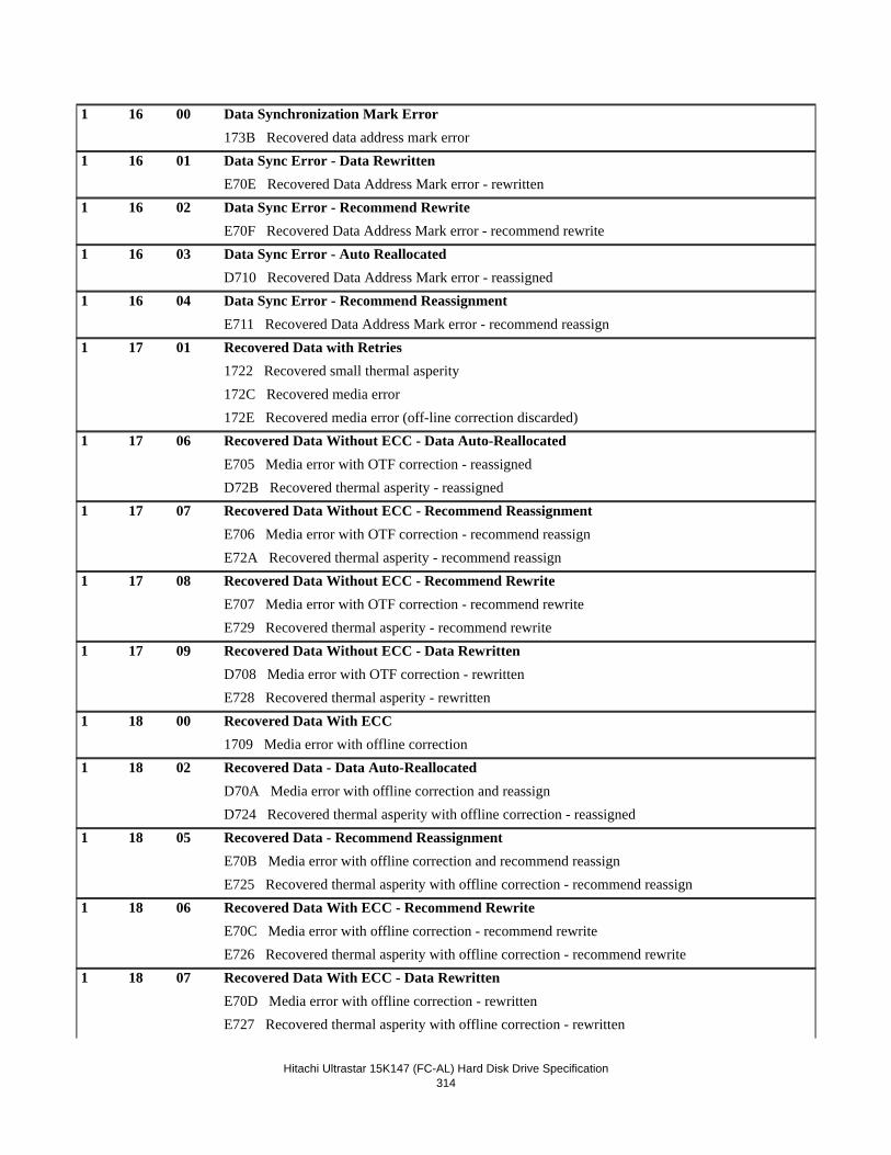
Hitachi Ultrastar 15K147 (FC-AL) Hard Disk Drive Specification314
1 16 00 Data Synchronization Mark Error173B Recovered data address mark error
1 16 01 Data Sync Error - Data RewrittenE70E Recovered Data Address Mark error - rewritten
1 16 02 Data Sync Error - Recommend RewriteE70F Recovered Data Address Mark error - recommend rewrite
1 16 03 Data Sync Error - Auto ReallocatedD710 Recovered Data Address Mark error - reassigned
1 16 04 Data Sync Error - Recommend ReassignmentE711 Recovered Data Address Mark error - recommend reassign
1 17 01 Recovered Data with Retries1722 Recovered small thermal asperity172C Recovered media error172E Recovered media error (off-line correction discarded)
1 17 06 Recovered Data Without ECC - Data Auto-ReallocatedE705 Media error with OTF correction - reassignedD72B Recovered thermal asperity - reassigned
1 17 07 Recovered Data Without ECC - Recommend ReassignmentE706 Media error with OTF correction - recommend reassignE72A Recovered thermal asperity - recommend reassign
1 17 08 Recovered Data Without ECC - Recommend RewriteE707 Media error with OTF correction - recommend rewriteE729 Recovered thermal asperity - recommend rewrite
1 17 09 Recovered Data Without ECC - Data RewrittenD708 Media error with OTF correction - rewrittenE728 Recovered thermal asperity - rewritten
1 18 00 Recovered Data With ECC1709 Media error with offline correction
1 18 02 Recovered Data - Data Auto-ReallocatedD70A Media error with offline correction and reassignD724 Recovered thermal asperity with offline correction - reassigned
1 18 05 Recovered Data - Recommend ReassignmentE70B Media error with offline correction and recommend reassignE725 Recovered thermal asperity with offline correction - recommend reassign
1 18 06 Recovered Data With ECC - Recommend RewriteE70C Media error with offline correction - recommend rewriteE726 Recovered thermal asperity with offline correction - recommend rewrite
1 18 07 Recovered Data With ECC - Data RewrittenE70D Media error with offline correction - rewrittenE727 Recovered thermal asperity with offline correction - rewritten
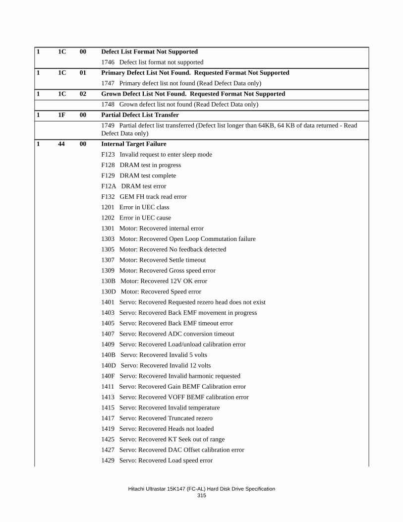
Hitachi Ultrastar 15K147 (FC-AL) Hard Disk Drive Specification315
1 1C 00 Defect List Format Not Supported1746 Defect list format not supported
1 1C 01 Primary Defect List Not Found. Requested Format Not Supported1747 Primary defect list not found (Read Defect Data only)
1 1C 02 Grown Defect List Not Found. Requested Format Not Supported1748 Grown defect list not found (Read Defect Data only)
1 1F 00 Partial Defect List Transfer1749 Partial defect list transferred (Defect list longer than 64KB, 64 KB of data returned - Read Defect Data only)
1 44 00 Internal Target FailureF123 Invalid request to enter sleep modeF128 DRAM test in progressF129 DRAM test completeF12A DRAM test errorF132 GEM FH track read error1201 Error in UEC class1202 Error in UEC cause1301 Motor: Recovered internal error1303 Motor: Recovered Open Loop Commutation failure1305 Motor: Recovered No feedback detected1307 Motor: Recovered Settle timeout1309 Motor: Recovered Gross speed error130B Motor: Recovered 12V OK error130D Motor: Recovered Speed error1401 Servo: Recovered Requested rezero head does not exist1403 Servo: Recovered Back EMF movement in progress1405 Servo: Recovered Back EMF timeout error1407 Servo: Recovered ADC conversion timeout1409 Servo: Recovered Load/unload calibration error140B Servo: Recovered Invalid 5 volts140D Servo: Recovered Invalid 12 volts140F Servo: Recovered Invalid harmonic requested1411 Servo: Recovered Gain BEMF Calibration error1413 Servo: Recovered VOFF BEMF calibration error1415 Servo: Recovered Invalid temperature1417 Servo: Recovered Truncated rezero1419 Servo: Recovered Heads not loaded1425 Servo: Recovered KT Seek out of range1427 Servo: Recovered DAC Offset calibration error1429 Servo: Recovered Load speed error
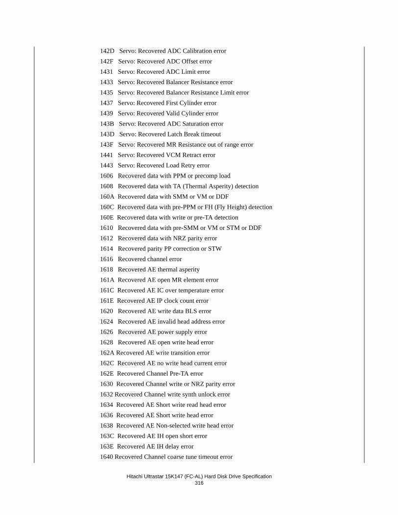
Hitachi Ultrastar 15K147 (FC-AL) Hard Disk Drive Specification316
142D Servo: Recovered ADC Calibration error142F Servo: Recovered ADC Offset error1431 Servo: Recovered ADC Limit error1433 Servo: Recovered Balancer Resistance error1435 Servo: Recovered Balancer Resistance Limit error1437 Servo: Recovered First Cylinder error1439 Servo: Recovered Valid Cylinder error143B Servo: Recovered ADC Saturation error143D Servo: Recovered Latch Break timeout143F Servo: Recovered MR Resistance out of range error1441 Servo: Recovered VCM Retract error1443 Servo: Recovered Load Retry error1606 Recovered data with PPM or precomp load1608 Recovered data with TA (Thermal Asperity) detection160A Recovered data with SMM or VM or DDF160C Recovered data with pre-PPM or FH (Fly Height) detection160E Recovered data with write or pre-TA detection1610 Recovered data with pre-SMM or VM or STM or DDF1612 Recovered data with NRZ parity error1614 Recovered parity PP correction or STW1616 Recovered channel error1618 Recovered AE thermal asperity161A Recovered AE open MR element error161C Recovered AE IC over temperature error161E Recovered AE IP clock count error1620 Recovered AE write data BLS error1624 Recovered AE invalid head address error1626 Recovered AE power supply error1628 Recovered AE open write head error162A Recovered AE write transition error162C Recovered AE no write head current error162E Recovered Channel Pre-TA error1630 Recovered Channel write or NRZ parity error1632 Recovered Channel write synth unlock error1634 Recovered AE Short write read head error1636 Recovered AE Short write head error1638 Recovered AE Non-selected write head error163C Recovered AE IH open short error163E Recovered AE IH delay error1640 Recovered Channel coarse tune timeout error
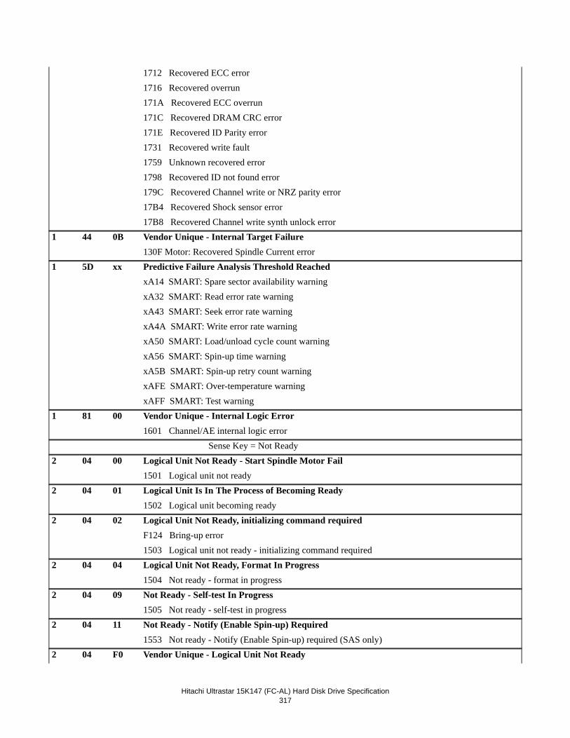
Hitachi Ultrastar 15K147 (FC-AL) Hard Disk Drive Specification317
1712 Recovered ECC error1716 Recovered overrun171A Recovered ECC overrun171C Recovered DRAM CRC error171E Recovered ID Parity error1731 Recovered write fault1759 Unknown recovered error1798 Recovered ID not found error179C Recovered Channel write or NRZ parity error17B4 Recovered Shock sensor error17B8 Recovered Channel write synth unlock error
1 44 0B Vendor Unique - Internal Target Failure130F Motor: Recovered Spindle Current error
1 5D xx Predictive Failure Analysis Threshold ReachedxA14 SMART: Spare sector availability warningxA32 SMART: Read error rate warningxA43 SMART: Seek error rate warningxA4A SMART: Write error rate warningxA50 SMART: Load/unload cycle count warningxA56 SMART: Spin-up time warningxA5B SMART: Spin-up retry count warningxAFE SMART: Over-temperature warningxAFF SMART: Test warning
1 81 00 Vendor Unique - Internal Logic Error1601 Channel/AE internal logic error Sense Key = Not Ready
2 04 00 Logical Unit Not Ready - Start Spindle Motor Fail1501 Logical unit not ready
2 04 01 Logical Unit Is In The Process of Becoming Ready1502 Logical unit becoming ready
2 04 02 Logical Unit Not Ready, initializing command requiredF124 Bring-up error1503 Logical unit not ready - initializing command required
2 04 04 Logical Unit Not Ready, Format In Progress1504 Not ready - format in progress
2 04 09 Not Ready - Self-test In Progress1505 Not ready - self-test in progress
2 04 11 Not Ready - Notify (Enable Spin-up) Required1553 Not ready - Notify (Enable Spin-up) required (SAS only)
2 04 F0 Vendor Unique - Logical Unit Not Ready
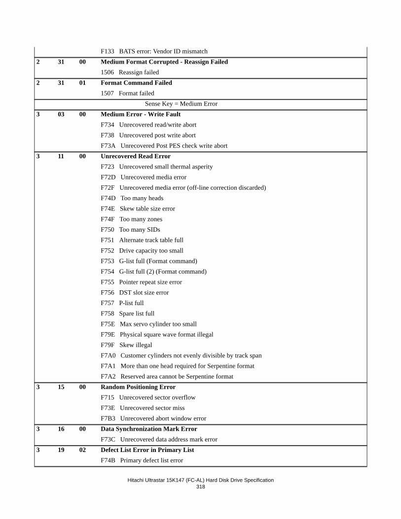
Hitachi Ultrastar 15K147 (FC-AL) Hard Disk Drive Specification318
F133 BATS error: Vendor ID mismatch2 31 00 Medium Format Corrupted - Reassign Failed
1506 Reassign failed2 31 01 Format Command Failed
1507 Format failed Sense Key = Medium Error
3 03 00 Medium Error - Write FaultF734 Unrecovered read/write abortF738 Unrecovered post write abortF73A Unrecovered Post PES check write abort
3 11 00 Unrecovered Read ErrorF723 Unrecovered small thermal asperityF72D Unrecovered media errorF72F Unrecovered media error (off-line correction discarded)F74D Too many headsF74E Skew table size errorF74F Too many zonesF750 Too many SIDsF751 Alternate track table fullF752 Drive capacity too smallF753 G-list full (Format command)F754 G-list full (2) (Format command)F755 Pointer repeat size errorF756 DST slot size errorF757 P-list fullF758 Spare list fullF75E Max servo cylinder too smallF79E Physical square wave format illegalF79F Skew illegalF7A0 Customer cylinders not evenly divisible by track spanF7A1 More than one head required for Serpentine formatF7A2 Reserved area cannot be Serpentine format
3 15 00 Random Positioning ErrorF715 Unrecovered sector overflowF73E Unrecovered sector missF7B3 Unrecovered abort window error
3 16 00 Data Synchronization Mark ErrorF73C Unrecovered data address mark error
3 19 02 Defect List Error in Primary ListF74B Primary defect list error
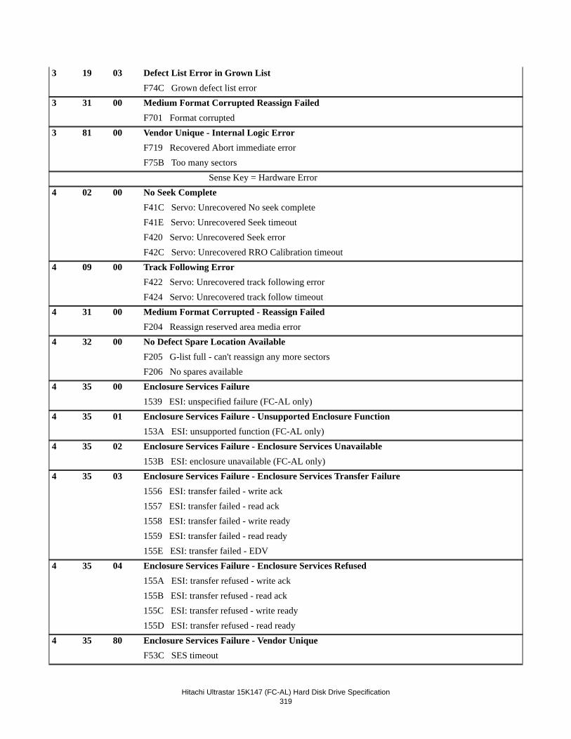
Hitachi Ultrastar 15K147 (FC-AL) Hard Disk Drive Specification319
3 19 03 Defect List Error in Grown ListF74C Grown defect list error
3 31 00 Medium Format Corrupted Reassign FailedF701 Format corrupted
3 81 00 Vendor Unique - Internal Logic ErrorF719 Recovered Abort immediate errorF75B Too many sectors Sense Key = Hardware Error
4 02 00 No Seek CompleteF41C Servo: Unrecovered No seek completeF41E Servo: Unrecovered Seek timeoutF420 Servo: Unrecovered Seek errorF42C Servo: Unrecovered RRO Calibration timeout
4 09 00 Track Following ErrorF422 Servo: Unrecovered track following errorF424 Servo: Unrecovered track follow timeout
4 31 00 Medium Format Corrupted - Reassign FailedF204 Reassign reserved area media error
4 32 00 No Defect Spare Location AvailableF205 G-list full - can't reassign any more sectorsF206 No spares available
4 35 00 Enclosure Services Failure1539 ESI: unspecified failure (FC-AL only)
4 35 01 Enclosure Services Failure - Unsupported Enclosure Function153A ESI: unsupported function (FC-AL only)
4 35 02 Enclosure Services Failure - Enclosure Services Unavailable153B ESI: enclosure unavailable (FC-AL only)
4 35 03 Enclosure Services Failure - Enclosure Services Transfer Failure1556 ESI: transfer failed - write ack1557 ESI: transfer failed - read ack1558 ESI: transfer failed - write ready1559 ESI: transfer failed - read ready155E ESI: transfer failed - EDV
4 35 04 Enclosure Services Failure - Enclosure Services Refused155A ESI: transfer refused - write ack155B ESI: transfer refused - read ack155C ESI: transfer refused - write ready155D ESI: transfer refused - read ready
4 35 80 Enclosure Services Failure - Vendor UniqueF53C SES timeout
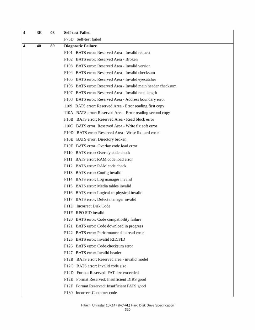
Hitachi Ultrastar 15K147 (FC-AL) Hard Disk Drive Specification320
4 3E 03 Self-test FailedF75D Self-test failed
4 40 80 Diagnostic FailureF101 BATS error: Reserved Area - Invalid requestF102 BATS error: Reserved Area - BrokenF103 BATS error: Reserved Area - Invalid versionF104 BATS error: Reserved Area - Invalid checksumF105 BATS error: Reserved Area - Invalid eyecatcherF106 BATS error: Reserved Area - Invalid main header checksumF107 BATS error: Reserved Area - Invalid read lengthF108 BATS error: Reserved Area - Address boundary error1109 BATS error: Reserved Area - Error reading first copy110A BATS error: Reserved Area - Error reading second copyF10B BATS error: Reserved Area - Read block error110C BATS error: Reserved Area - Write fix soft errorF10D BATS error: Reserved Area - Write fix hard errorF10E BATS error: Directory brokenF10F BATS error: Overlay code load errorF110 BATS error: Overlay code checkF111 BATS error: RAM code load errorF112 BATS error: RAM code checkF113 BATS error: Config invalidF114 BATS error: Log manager invalidF115 BATS error: Media tables invalidF116 BATS error: Logical-to-physical invalidF117 BATS error: Defect manager invalidF11D Incorrect Disk CodeF11F RPO SID invalidF120 BATS error: Code compatibility failureF121 BATS error: Code download in progressF122 BATS error: Performance data read errorF125 BATS error: Invalid RID/FIDF126 BATS error: Code checksum errorF127 BATS error: Invalid headerF12B BATS error: Reserved area - invalid modelF12C BATS error: Invalid code sizeF12D Format Reserved: FAT size exceededF12E Format Reserved: Insufficient DIRS goodF12F Format Reserved: Insufficient FATS goodF130 Incorrect Customer code
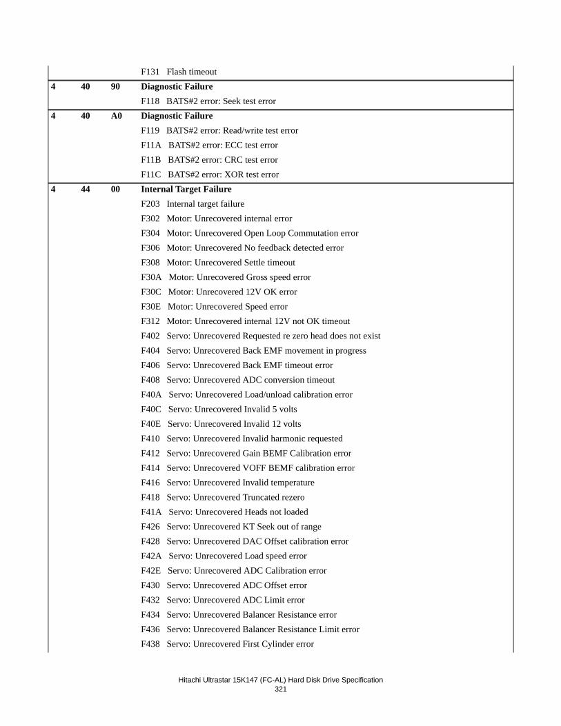
Hitachi Ultrastar 15K147 (FC-AL) Hard Disk Drive Specification321
F131 Flash timeout4 40 90 Diagnostic Failure
F118 BATS#2 error: Seek test error4 40 A0 Diagnostic Failure
F119 BATS#2 error: Read/write test errorF11A BATS#2 error: ECC test errorF11B BATS#2 error: CRC test errorF11C BATS#2 error: XOR test error
4 44 00 Internal Target FailureF203 Internal target failureF302 Motor: Unrecovered internal errorF304 Motor: Unrecovered Open Loop Commutation errorF306 Motor: Unrecovered No feedback detected errorF308 Motor: Unrecovered Settle timeoutF30A Motor: Unrecovered Gross speed errorF30C Motor: Unrecovered 12V OK errorF30E Motor: Unrecovered Speed errorF312 Motor: Unrecovered internal 12V not OK timeoutF402 Servo: Unrecovered Requested re zero head does not existF404 Servo: Unrecovered Back EMF movement in progressF406 Servo: Unrecovered Back EMF timeout errorF408 Servo: Unrecovered ADC conversion timeoutF40A Servo: Unrecovered Load/unload calibration errorF40C Servo: Unrecovered Invalid 5 voltsF40E Servo: Unrecovered Invalid 12 voltsF410 Servo: Unrecovered Invalid harmonic requestedF412 Servo: Unrecovered Gain BEMF Calibration errorF414 Servo: Unrecovered VOFF BEMF calibration errorF416 Servo: Unrecovered Invalid temperatureF418 Servo: Unrecovered Truncated rezeroF41A Servo: Unrecovered Heads not loadedF426 Servo: Unrecovered KT Seek out of rangeF428 Servo: Unrecovered DAC Offset calibration errorF42A Servo: Unrecovered Load speed errorF42E Servo: Unrecovered ADC Calibration errorF430 Servo: Unrecovered ADC Offset errorF432 Servo: Unrecovered ADC Limit errorF434 Servo: Unrecovered Balancer Resistance errorF436 Servo: Unrecovered Balancer Resistance Limit errorF438 Servo: Unrecovered First Cylinder error
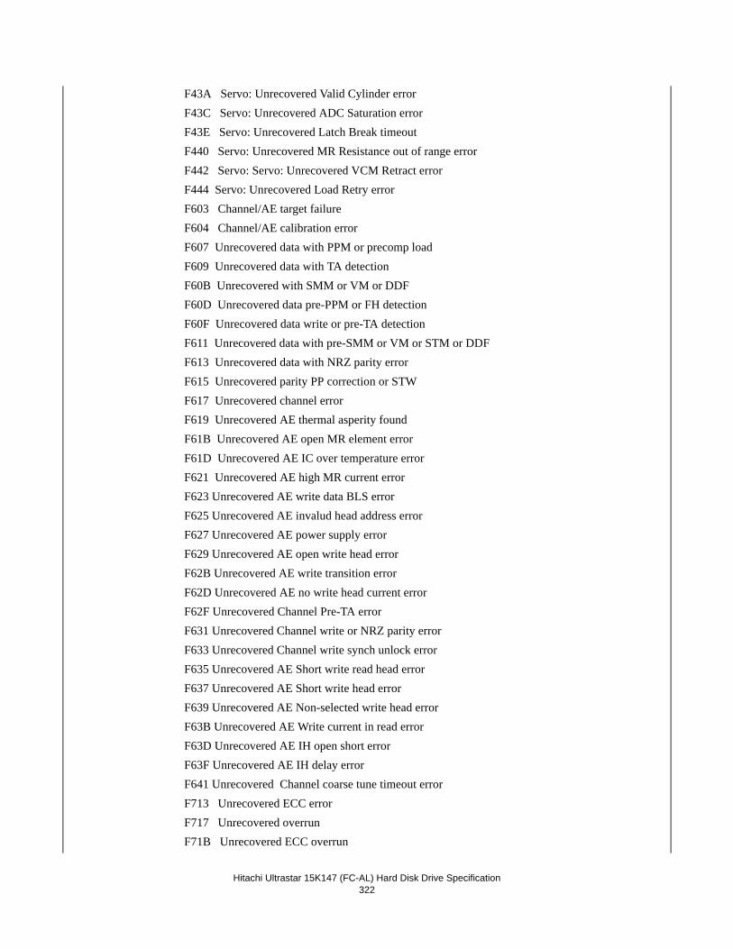
Hitachi Ultrastar 15K147 (FC-AL) Hard Disk Drive Specification322
F43A Servo: Unrecovered Valid Cylinder errorF43C Servo: Unrecovered ADC Saturation errorF43E Servo: Unrecovered Latch Break timeoutF440 Servo: Unrecovered MR Resistance out of range errorF442 Servo: Servo: Unrecovered VCM Retract errorF444 Servo: Unrecovered Load Retry errorF603 Channel/AE target failureF604 Channel/AE calibration errorF607 Unrecovered data with PPM or precomp loadF609 Unrecovered data with TA detectionF60B Unrecovered with SMM or VM or DDFF60D Unrecovered data pre-PPM or FH detectionF60F Unrecovered data write or pre-TA detectionF611 Unrecovered data with pre-SMM or VM or STM or DDFF613 Unrecovered data with NRZ parity errorF615 Unrecovered parity PP correction or STWF617 Unrecovered channel errorF619 Unrecovered AE thermal asperity foundF61B Unrecovered AE open MR element errorF61D Unrecovered AE IC over temperature errorF621 Unrecovered AE high MR current errorF623 Unrecovered AE write data BLS errorF625 Unrecovered AE invalud head address errorF627 Unrecovered AE power supply errorF629 Unrecovered AE open write head errorF62B Unrecovered AE write transition errorF62D Unrecovered AE no write head current error F62F Unrecovered Channel Pre-TA errorF631 Unrecovered Channel write or NRZ parity errorF633 Unrecovered Channel write synch unlock errorF635 Unrecovered AE Short write read head errorF637 Unrecovered AE Short write head errorF639 Unrecovered AE Non-selected write head errorF63B Unrecovered AE Write current in read errorF63D Unrecovered AE IH open short errorF63F Unrecovered AE IH delay errorF641 Unrecovered Channel coarse tune timeout errorF713 Unrecovered ECC errorF717 Unrecovered overrunF71B Unrecovered ECC overrun
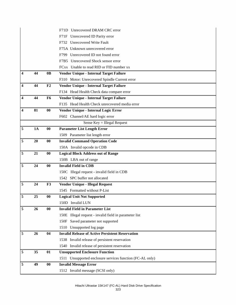
Hitachi Ultrastar 15K147 (FC-AL) Hard Disk Drive Specification323
F71D Unrecovered DRAM CRC errorF71F Unrecovered ID Parity errorF732 Unrecovered Write FaultF75A Unknown unrecovered errorF799 Unrecovered ID not found errorF7B5 Unrecovered Shock sensor errorFCxx Unable to read RID or FID number xx
4 44 0B Vendor Unique - Internal Target FailureF310 Motor: Unrecovered Spindle Current error
4 44 F2 Vendor Unique - Internal Target FailureF134 Head Health Check data compare error
4 44 F6 Vendor Unique - Internal Target FailureF135 Head Health Check unrecovered media error
4 81 00 Vendor Unique - Internal Logic ErrorF602 Channel/AE hard logic error Sense Key = Illegal Request
5 1A 00 Parameter List Length Error1509 Parameter list length error
5 20 00 Invalid Command Operation Code150A Invalid opcode in CDB
5 21 00 Logical Block Address out of Range150B LBA out of range
5 24 00 Invalid Field in CDB150C Illegal request - invalid field in CDB1542 SPC buffer not allocated
5 24 F3 Vendor Unique - Illegal Request1545 Formatted without P-List
5 25 00 Logical Unit Not Supported150D Invalid LUN
5 26 00 Invalid Field in Parameter List150E Illegal request - invalid field in parameter list150F Saved parameter not supported1510 Unsupported log page
5 26 04 Invalid Release of Active Persistent Reservation1538 Invalid release of persistent reservation1540 Invalid release of persistent reservation
5 35 01 Unsupported Enclosure Function1511 Unsupported enclosure services function (FC-AL only)
5 49 00 Invalid Message Error1512 Invalid message (SCSI only)
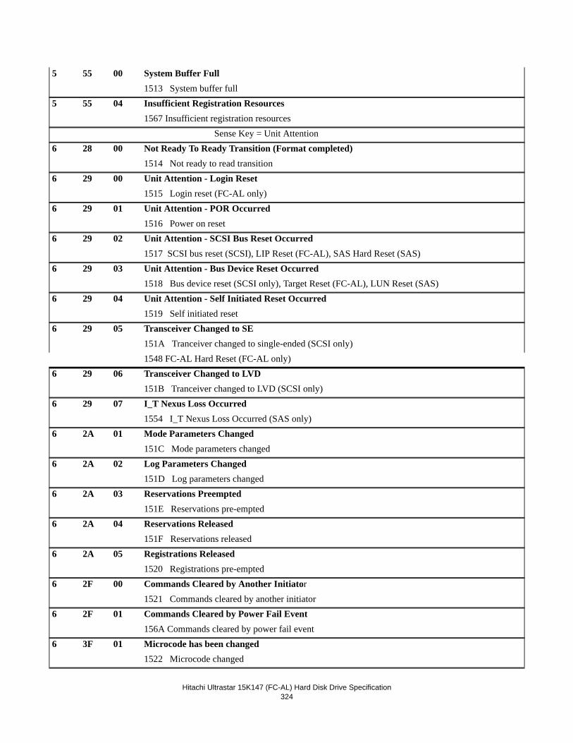
Hitachi Ultrastar 15K147 (FC-AL) Hard Disk Drive Specification324
5 55 00 System Buffer Full1513 System buffer full
5 55 04 Insufficient Registration Resources1567 Insufficient registration resources Sense Key = Unit Attention
6 28 00 Not Ready To Ready Transition (Format completed)1514 Not ready to read transition
6 29 00 Unit Attention - Login Reset1515 Login reset (FC-AL only)
6 29 01 Unit Attention - POR Occurred1516 Power on reset
6 29 02 Unit Attention - SCSI Bus Reset Occurred1517 SCSI bus reset (SCSI), LIP Reset (FC-AL), SAS Hard Reset (SAS)
6 29 03 Unit Attention - Bus Device Reset Occurred1518 Bus device reset (SCSI only), Target Reset (FC-AL), LUN Reset (SAS)
6 29 04 Unit Attention - Self Initiated Reset Occurred1519 Self initiated reset
6 29 05 Transceiver Changed to SE151A Tranceiver changed to single-ended (SCSI only)1548 FC-AL Hard Reset (FC-AL only)
6 29 06 Transceiver Changed to LVD151B Tranceiver changed to LVD (SCSI only)
6 29 07 I_T Nexus Loss Occurred1554 I_T Nexus Loss Occurred (SAS only)
6 2A 01 Mode Parameters Changed151C Mode parameters changed
6 2A 02 Log Parameters Changed151D Log parameters changed
6 2A 03 Reservations Preempted151E Reservations pre-empted
6 2A 04 Reservations Released151F Reservations released
6 2A 05 Registrations Released1520 Registrations pre-empted
6 2F 00 Commands Cleared by Another Initiator1521 Commands cleared by another initiator
6 2F 01 Commands Cleared by Power Fail Event156A Commands cleared by power fail event
6 3F 01 Microcode has been changed1522 Microcode changed
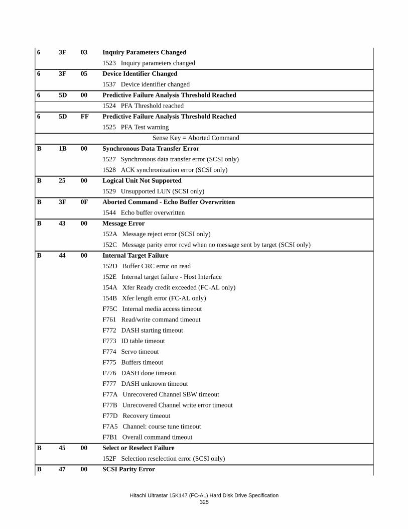
Hitachi Ultrastar 15K147 (FC-AL) Hard Disk Drive Specification325
6 3F 03 Inquiry Parameters Changed1523 Inquiry parameters changed
6 3F 05 Device Identifier Changed1537 Device identifier changed
6 5D 00 Predictive Failure Analysis Threshold Reached1524 PFA Threshold reached
6 5D FF Predictive Failure Analysis Threshold Reached1525 PFA Test warning Sense Key = Aborted Command
B 1B 00 Synchronous Data Transfer Error1527 Synchronous data transfer error (SCSI only)1528 ACK synchronization error (SCSI only)
B 25 00 Logical Unit Not Supported1529 Unsupported LUN (SCSI only)
B 3F 0F Aborted Command - Echo Buffer Overwritten1544 Echo buffer overwritten
B 43 00 Message Error152A Message reject error (SCSI only)152C Message parity error rcvd when no message sent by target (SCSI only)
B 44 00 Internal Target Failure152D Buffer CRC error on read152E Internal target failure - Host Interface154A Xfer Ready credit exceeded (FC-AL only)154B Xfer length error (FC-AL only)F75C Internal media access timeoutF761 Read/write command timeoutF772 DASH starting timeoutF773 ID table timeoutF774 Servo timeoutF775 Buffers timeoutF776 DASH done timeoutF777 DASH unknown timeoutF77A Unrecovered Channel SBW timeoutF77B Unrecovered Channel write error timeoutF77D Recovery timeoutF7A5 Channel: course tune timeoutF7B1 Overall command timeout
B 45 00 Select or Reselect Failure152F Selection reselection error (SCSI only)
B 47 00 SCSI Parity Error
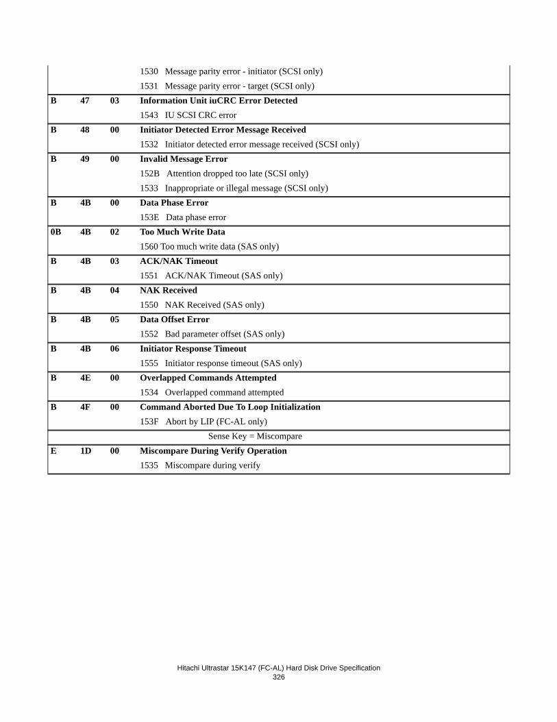
Hitachi Ultrastar 15K147 (FC-AL) Hard Disk Drive Specification326
1530 Message parity error - initiator (SCSI only)1531 Message parity error - target (SCSI only)
B 47 03 Information Unit iuCRC Error Detected1543 IU SCSI CRC error
B 48 00 Initiator Detected Error Message Received1532 Initiator detected error message received (SCSI only)
B 49 00 Invalid Message Error152B Attention dropped too late (SCSI only)1533 Inappropriate or illegal message (SCSI only)
B 4B 00 Data Phase Error153E Data phase error
0B 4B 02 Too Much Write Data1560 Too much write data (SAS only)
B 4B 03 ACK/NAK Timeout1551 ACK/NAK Timeout (SAS only)
B 4B 04 NAK Received1550 NAK Received (SAS only)
B 4B 05 Data Offset Error1552 Bad parameter offset (SAS only)
B 4B 06 Initiator Response Timeout1555 Initiator response timeout (SAS only)
B 4E 00 Overlapped Commands Attempted1534 Overlapped command attempted
B 4F 00 Command Aborted Due To Loop Initialization153F Abort by LIP (FC-AL only) Sense Key = Miscompare
E 1D 00 Miscompare During Verify Operation1535 Miscompare during verify
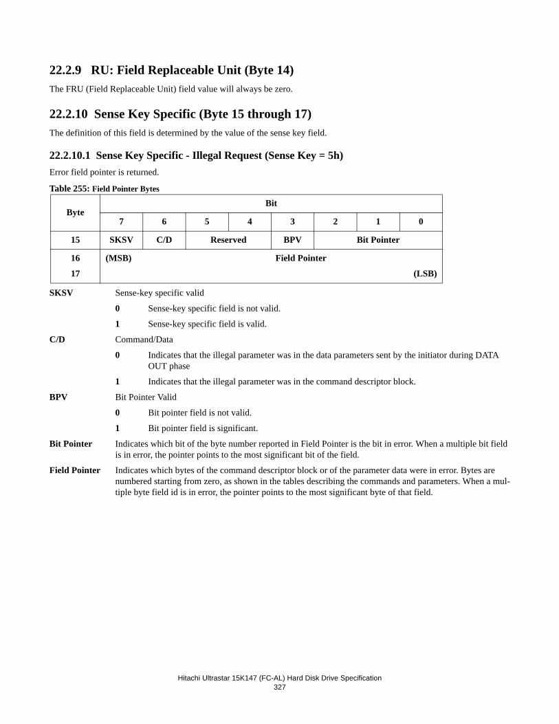
Hitachi Ultrastar 15K147 (FC-AL) Hard Disk Drive Specification327
22.2.9 RU: Field Replaceable Unit (Byte 14)The FRU (Field Replaceable Unit) field value will always be zero.
22.2.10 Sense Key Specific (Byte 15 through 17)The definition of this field is determined by the value of the sense key field.
22.2.10.1 Sense Key Specific - Illegal Request (Sense Key = 5h)Error field pointer is returned.
Table 255: Field Pointer Bytes
SKSV Sense-key specific valid
0 Sense-key specific field is not valid.
1 Sense-key specific field is valid.
C/D Command/Data
0 Indicates that the illegal parameter was in the data parameters sent by the initiator during DATA OUT phase
1 Indicates that the illegal parameter was in the command descriptor block.
BPV Bit Pointer Valid
0 Bit pointer field is not valid.
1 Bit pointer field is significant.
Bit Pointer Indicates which bit of the byte number reported in Field Pointer is the bit in error. When a multiple bit field is in error, the pointer points to the most significant bit of the field.
Field Pointer Indicates which bytes of the command descriptor block or of the parameter data were in error. Bytes are numbered starting from zero, as shown in the tables describing the commands and parameters. When a mul-tiple byte field id is in error, the pointer points to the most significant byte of that field.
ByteBit
7 6 5 4 3 2 1 0
15 SKSV C/D Reserved BPV Bit Pointer
16
17
(MSB) Field Pointer
(LSB)
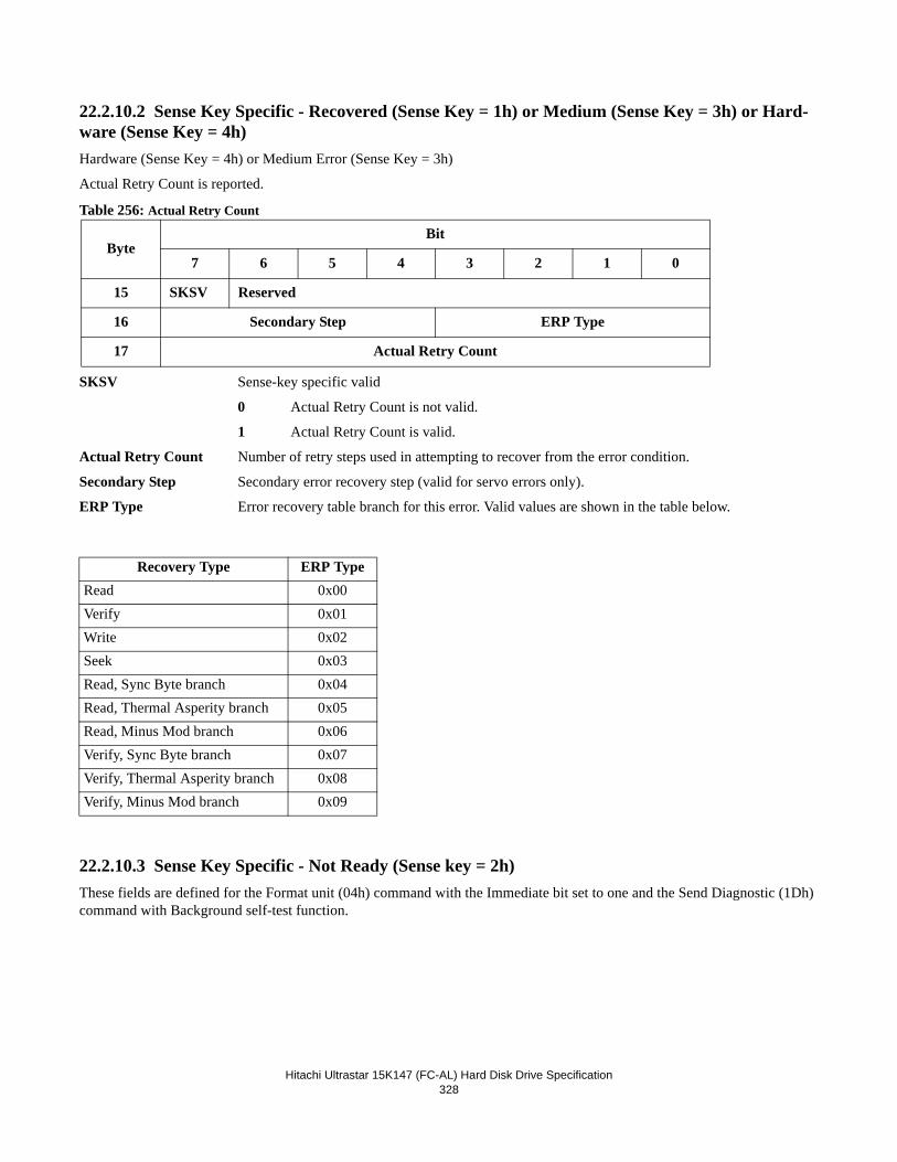
Hitachi Ultrastar 15K147 (FC-AL) Hard Disk Drive Specification328
22.2.10.2 Sense Key Specific - Recovered (Sense Key = 1h) or Medium (Sense Key = 3h) or Hard-ware (Sense Key = 4h)Hardware (Sense Key = 4h) or Medium Error (Sense Key = 3h)
Actual Retry Count is reported.
Table 256: Actual Retry Count
SKSV Sense-key specific valid
0 Actual Retry Count is not valid.
1 Actual Retry Count is valid.
Actual Retry Count Number of retry steps used in attempting to recover from the error condition.
Secondary Step Secondary error recovery step (valid for servo errors only).
ERP Type Error recovery table branch for this error. Valid values are shown in the table below.
22.2.10.3 Sense Key Specific - Not Ready (Sense key = 2h)These fields are defined for the Format unit (04h) command with the Immediate bit set to one and the Send Diagnostic (1Dh) command with Background self-test function.
ByteBit
7 6 5 4 3 2 1 0
15 SKSV Reserved
16 Secondary Step ERP Type
17 Actual Retry Count
Recovery Type ERP TypeRead 0x00Verify 0x01Write 0x02Seek 0x03Read, Sync Byte branch 0x04Read, Thermal Asperity branch 0x05Read, Minus Mod branch 0x06Verify, Sync Byte branch 0x07Verify, Thermal Asperity branch 0x08Verify, Minus Mod branch 0x09
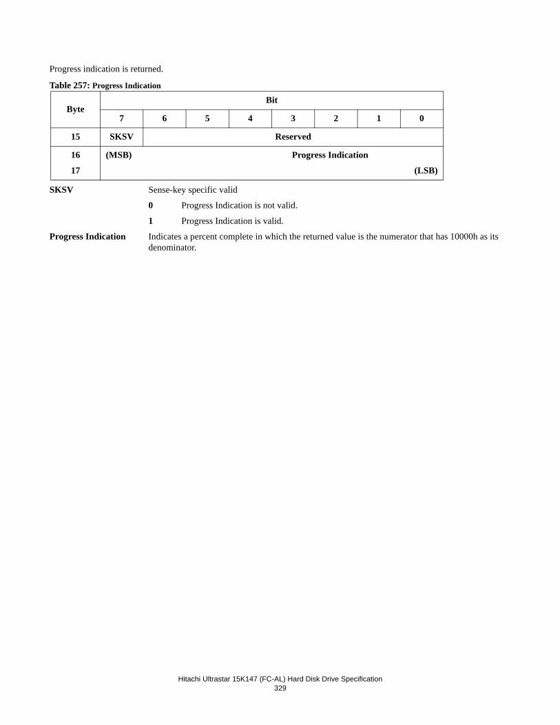
Hitachi Ultrastar 15K147 (FC-AL) Hard Disk Drive Specification329
Progress indication is returned.
Table 257: Progress Indication
SKSV Sense-key specific valid
0 Progress Indication is not valid.
1 Progress Indication is valid.
Progress Indication Indicates a percent complete in which the returned value is the numerator that has 10000h as its denominator.
ByteBit
7 6 5 4 3 2 1 0
15 SKSV Reserved
16
17
(MSB) Progress Indication
(LSB)
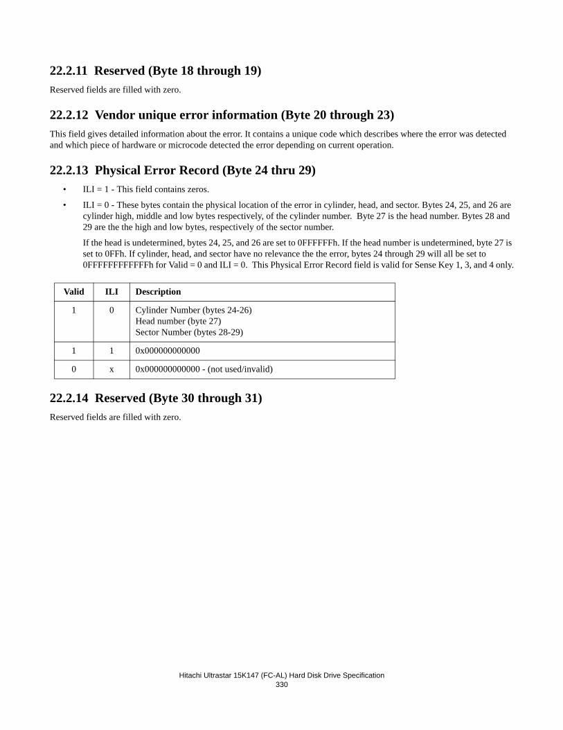
Hitachi Ultrastar 15K147 (FC-AL) Hard Disk Drive Specification330
22.2.11 Reserved (Byte 18 through 19)Reserved fields are filled with zero.
22.2.12 Vendor unique error information (Byte 20 through 23)This field gives detailed information about the error. It contains a unique code which describes where the error was detected and which piece of hardware or microcode detected the error depending on current operation.
22.2.13 Physical Error Record (Byte 24 thru 29)• ILI = 1 - This field contains zeros.
• ILI = 0 - These bytes contain the physical location of the error in cylinder, head, and sector. Bytes 24, 25, and 26 are cylinder high, middle and low bytes respectively, of the cylinder number. Byte 27 is the head number. Bytes 28 and 29 are the the high and low bytes, respectively of the sector number.
If the head is undetermined, bytes 24, 25, and 26 are set to 0FFFFFFh. If the head number is undetermined, byte 27 is set to 0FFh. If cylinder, head, and sector have no relevance the the error, bytes 24 through 29 will all be set to 0FFFFFFFFFFFFh for Valid = 0 and ILI = 0. This Physical Error Record field is valid for Sense Key 1, 3, and 4 only.
22.2.14 Reserved (Byte 30 through 31)Reserved fields are filled with zero.
Valid ILI Description
1 0 Cylinder Number (bytes 24-26)Head number (byte 27)Sector Number (bytes 28-29)
1 1 0x000000000000
0 x 0x000000000000 - (not used/invalid)
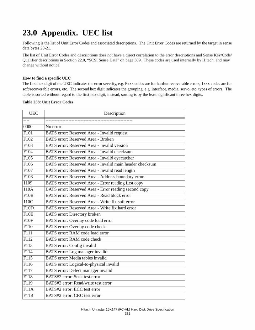
Hitachi Ultrastar 15K147 (FC-AL) Hard Disk Drive Specification331
23.0 Appendix. UEC listFollowing is the list of Unit Error Codes and associated descriptions. The Unit Error Codes are returned by the target in sense data bytes 20-21.
The list of Unit Error Codes and descriptions does not have a direct correlation to the error descriptions and Sense Key/Code/Qualifier descriptions in Section 22.0, “SCSI Sense Data” on page 309. These codes are used internally by Hitachi and may change without notice.
How to find a specific UECThe first hex digit of the UEC indicates the error severity, e.g. Fxxx codes are for hard/unrecoverable errors, 1xxx codes are for soft/recoverable errors, etc. The second hex digit indicates the grouping, e.g. interface, media, servo, etc. types of errors. The table is sorted without regard to the first hex digit; instead, sorting is by the least significant three hex digits.
Table 258: Unit Error Codes
UEC Description---- ---------------------------------------------------------0000 No errorF101 BATS error: Reserved Area - Invalid requestF102 BATS error: Reserved Area - BrokenF103 BATS error: Reserved Area - Invalid versionF104 BATS error: Reserved Area - Invalid checksumF105 BATS error: Reserved Area - Invalid eyecatcherF106 BATS error: Reserved Area - Invalid main header checksumF107 BATS error: Reserved Area - Invalid read lengthF108 BATS error: Reserved Area - Address boundary error1109 BATS error: Reserved Area - Error reading first copy110A BATS error: Reserved Area - Error reading second copyF10B BATS error: Reserved Area - Read block error110C BATS error: Reserved Area - Write fix soft errorF10D BATS error: Reserved Area - Write fix hard errorF10E BATS error: Directory brokenF10F BATS error: Overlay code load errorF110 BATS error: Overlay code checkF111 BATS error: RAM code load errorF112 BATS error: RAM code checkF113 BATS error: Config invalidF114 BATS error: Log manager invalidF115 BATS error: Media tables invalidF116 BATS error: Logical-to-physical invalidF117 BATS error: Defect manager invalidF118 BATS#2 error: Seek test errorF119 BATS#2 error: Read/write test errorF11A BATS#2 error: ECC test errorF11B BATS#2 error: CRC test error
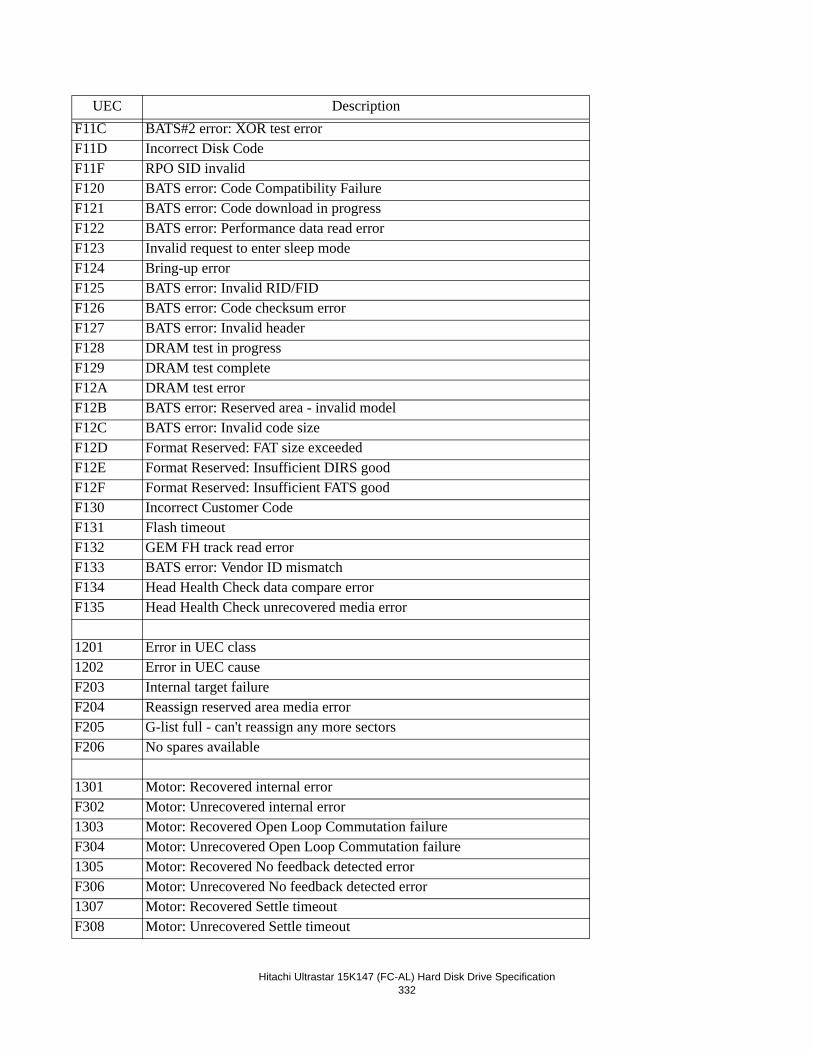
Hitachi Ultrastar 15K147 (FC-AL) Hard Disk Drive Specification332
F11C BATS#2 error: XOR test errorF11D Incorrect Disk CodeF11F RPO SID invalidF120 BATS error: Code Compatibility FailureF121 BATS error: Code download in progressF122 BATS error: Performance data read errorF123 Invalid request to enter sleep modeF124 Bring-up errorF125 BATS error: Invalid RID/FIDF126 BATS error: Code checksum errorF127 BATS error: Invalid headerF128 DRAM test in progressF129 DRAM test completeF12A DRAM test errorF12B BATS error: Reserved area - invalid modelF12C BATS error: Invalid code sizeF12D Format Reserved: FAT size exceededF12E Format Reserved: Insufficient DIRS goodF12F Format Reserved: Insufficient FATS goodF130 Incorrect Customer CodeF131 Flash timeoutF132 GEM FH track read errorF133 BATS error: Vendor ID mismatchF134 Head Health Check data compare errorF135 Head Health Check unrecovered media error
1201 Error in UEC class1202 Error in UEC causeF203 Internal target failureF204 Reassign reserved area media errorF205 G-list full - can't reassign any more sectorsF206 No spares available
1301 Motor: Recovered internal errorF302 Motor: Unrecovered internal error1303 Motor: Recovered Open Loop Commutation failureF304 Motor: Unrecovered Open Loop Commutation failure1305 Motor: Recovered No feedback detected errorF306 Motor: Unrecovered No feedback detected error1307 Motor: Recovered Settle timeoutF308 Motor: Unrecovered Settle timeout
UEC Description
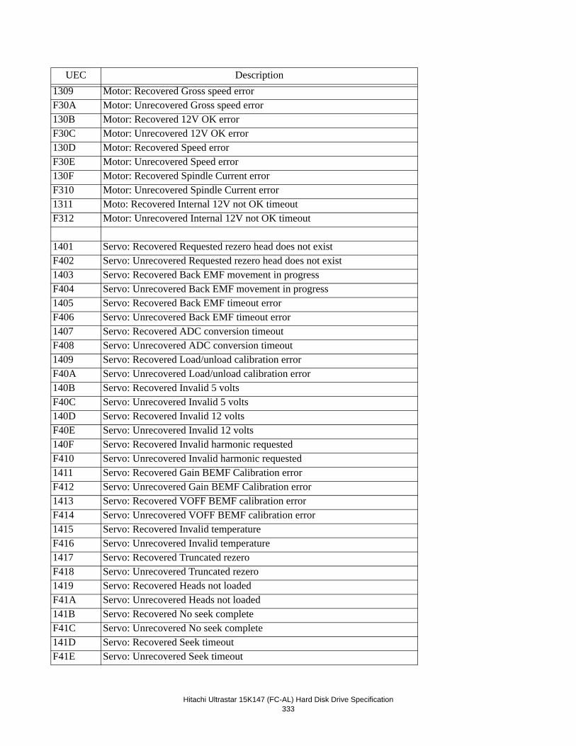
Hitachi Ultrastar 15K147 (FC-AL) Hard Disk Drive Specification333
1309 Motor: Recovered Gross speed errorF30A Motor: Unrecovered Gross speed error130B Motor: Recovered 12V OK errorF30C Motor: Unrecovered 12V OK error130D Motor: Recovered Speed errorF30E Motor: Unrecovered Speed error130F Motor: Recovered Spindle Current errorF310 Motor: Unrecovered Spindle Current error1311 Moto: Recovered Internal 12V not OK timeoutF312 Motor: Unrecovered Internal 12V not OK timeout
1401 Servo: Recovered Requested rezero head does not existF402 Servo: Unrecovered Requested rezero head does not exist1403 Servo: Recovered Back EMF movement in progressF404 Servo: Unrecovered Back EMF movement in progress1405 Servo: Recovered Back EMF timeout errorF406 Servo: Unrecovered Back EMF timeout error1407 Servo: Recovered ADC conversion timeoutF408 Servo: Unrecovered ADC conversion timeout1409 Servo: Recovered Load/unload calibration errorF40A Servo: Unrecovered Load/unload calibration error140B Servo: Recovered Invalid 5 voltsF40C Servo: Unrecovered Invalid 5 volts140D Servo: Recovered Invalid 12 voltsF40E Servo: Unrecovered Invalid 12 volts140F Servo: Recovered Invalid harmonic requestedF410 Servo: Unrecovered Invalid harmonic requested1411 Servo: Recovered Gain BEMF Calibration errorF412 Servo: Unrecovered Gain BEMF Calibration error1413 Servo: Recovered VOFF BEMF calibration errorF414 Servo: Unrecovered VOFF BEMF calibration error1415 Servo: Recovered Invalid temperatureF416 Servo: Unrecovered Invalid temperature1417 Servo: Recovered Truncated rezeroF418 Servo: Unrecovered Truncated rezero1419 Servo: Recovered Heads not loadedF41A Servo: Unrecovered Heads not loaded141B Servo: Recovered No seek completeF41C Servo: Unrecovered No seek complete141D Servo: Recovered Seek timeoutF41E Servo: Unrecovered Seek timeout
UEC Description
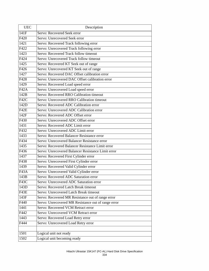
Hitachi Ultrastar 15K147 (FC-AL) Hard Disk Drive Specification334
141F Servo: Recovered Seek errorF420 Servo: Unrecovered Seek error1421 Servo: Recovered Track following errorF422 Servo: Unrecovered Track following error1423 Servo: Recovered Track follow timeoutF424 Servo: Unrecovered Track follow timeout1425 Servo: Recovered KT Seek out of rangeF426 Servo: Unrecovered KT Seek out of range1427 Servo: Recovered DAC Offset calibration errorF428 Servo: Unrecovered DAC Offset calibration error1429 Servo: Recovered Load speed errorF42A Servo: Unrecovered Load speed error142B Servo: Recovered RRO Calibration timeoutF42C Servo: Unrecovered RRO Calibration timeout142D Servo: Recovered ADC Calibration errorF42E Servo: Unrecovered ADC Calibration error142F Servo: Recovered ADC Offset errorF430 Servo: Unrecovered ADC Offset error1431 Servo: Recovered ADC Limit errorF432 Servo: Unrecovered ADC Limit error1433 Servo: Recovered Balancer Resistance errorF434 Servo: Unrecovered Balancer Resistance error1435 Servo: Recovered Balancer Resistance Limit errorF436 Servo: Unrecovered Balancer Resistance Limit error1437 Servo: Recovered First Cylinder errorF438 Servo: Unrecovered First Cylinder error1439 Servo: Recovered Valid Cylinder errorF43A Servo: Unrecovered Valid Cylinder error143B Servo: Recovered ADC Saturation errorF43C Servo: Unrecovered ADC Saturation error143D Servo: Recovered Latch Break timeoutF43E Servo: Unrecovered Latch Break timeout143F Servo: Recovered MR Resistance out of range errorF440 Servo: Unrecovered MR Resistance out of range error1441 Servo: Recovered VCM Retract errorF442 Servo: Unrecovered VCM Retract error1443 Servo: Recovered Load Retry errorF444 Servo: Unrecovered Load Retry error
1501 Logical unit not ready1502 Logical unit becoming ready
UEC Description
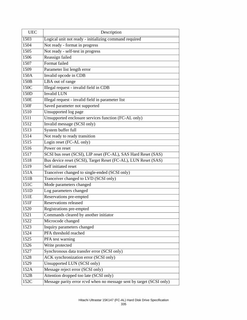
Hitachi Ultrastar 15K147 (FC-AL) Hard Disk Drive Specification335
1503 Logical unit not ready - initializing command required1504 Not ready - format in progress1505 Not ready - self-test in progress1506 Reassign failed1507 Format failed1509 Parameter list length error150A Invalid opcode in CDB150B LBA out of range150C Illegal request - invalid field in CDB150D Invalid LUN150E Illegal request - invalid field in parameter list150F Saved parameter not supported1510 Unsupported log page1511 Unsupported enclosure services function (FC-AL only)1512 Invalid message (SCSI only)1513 System buffer full1514 Not ready to ready transition1515 Login reset (FC-AL only)1516 Power on reset1517 SCSI bus reset (SCSI), LIP reset (FC-AL), SAS Hard Reset (SAS)1518 Bus device reset (SCSI), Target Reset (FC-AL), LUN Reset (SAS)1519 Self initiated reset151A Tranceiver changed to single-ended (SCSI only)151B Tranceiver changed to LVD (SCSI only)151C Mode parameters changed151D Log parameters changed151E Reservations pre-empted151F Reservations released1520 Registrations pre-empted1521 Commands cleared by another initiator1522 Microcode changed1523 Inquiry parameters changed1524 PFA threshold reached1525 PFA test warning1526 Write protected1527 Synchronous data transfer error (SCSI only)1528 ACK synchronization error (SCSI only)1529 Unsupported LUN (SCSI only)152A Message reject error (SCSI only)152B Attention dropped too late (SCSI only)152C Message parity error rcvd when no message sent by target (SCSI only)
UEC Description
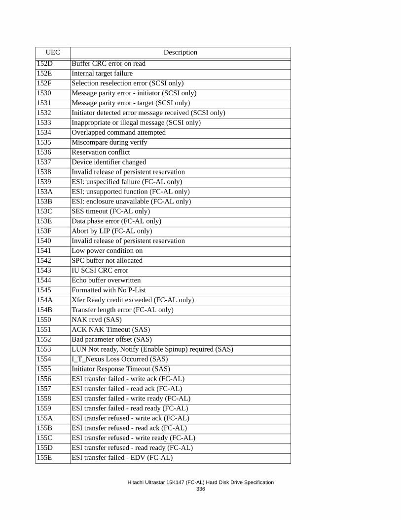
Hitachi Ultrastar 15K147 (FC-AL) Hard Disk Drive Specification336
152D Buffer CRC error on read152E Internal target failure152F Selection reselection error (SCSI only)1530 Message parity error - initiator (SCSI only)1531 Message parity error - target (SCSI only)1532 Initiator detected error message received (SCSI only)1533 Inappropriate or illegal message (SCSI only)1534 Overlapped command attempted1535 Miscompare during verify1536 Reservation conflict1537 Device identifier changed1538 Invalid release of persistent reservation1539 ESI: unspecified failure (FC-AL only)153A ESI: unsupported function (FC-AL only)153B ESI: enclosure unavailable (FC-AL only)153C SES timeout (FC-AL only)153E Data phase error (FC-AL only)153F Abort by LIP (FC-AL only)1540 Invalid release of persistent reservation1541 Low power condition on1542 SPC buffer not allocated1543 IU SCSI CRC error1544 Echo buffer overwritten1545 Formatted with No P-List154A Xfer Ready credit exceeded (FC-AL only)154B Transfer length error (FC-AL only)1550 NAK rcvd (SAS)1551 ACK NAK Timeout (SAS)1552 Bad parameter offset (SAS)1553 LUN Not ready, Notify (Enable Spinup) required (SAS)1554 I_T_Nexus Loss Occurred (SAS)1555 Initiator Response Timeout (SAS)1556 ESI transfer failed - write ack (FC-AL)1557 ESI transfer failed - read ack (FC-AL)1558 ESI transfer failed - write ready (FC-AL)1559 ESI transfer failed - read ready (FC-AL)155A ESI transfer refused - write ack (FC-AL)155B ESI transfer refused - read ack (FC-AL)155C ESI transfer refused - write ready (FC-AL)155D ESI transfer refused - read ready (FC-AL)155E ESI transfer failed - EDV (FC-AL)
UEC Description
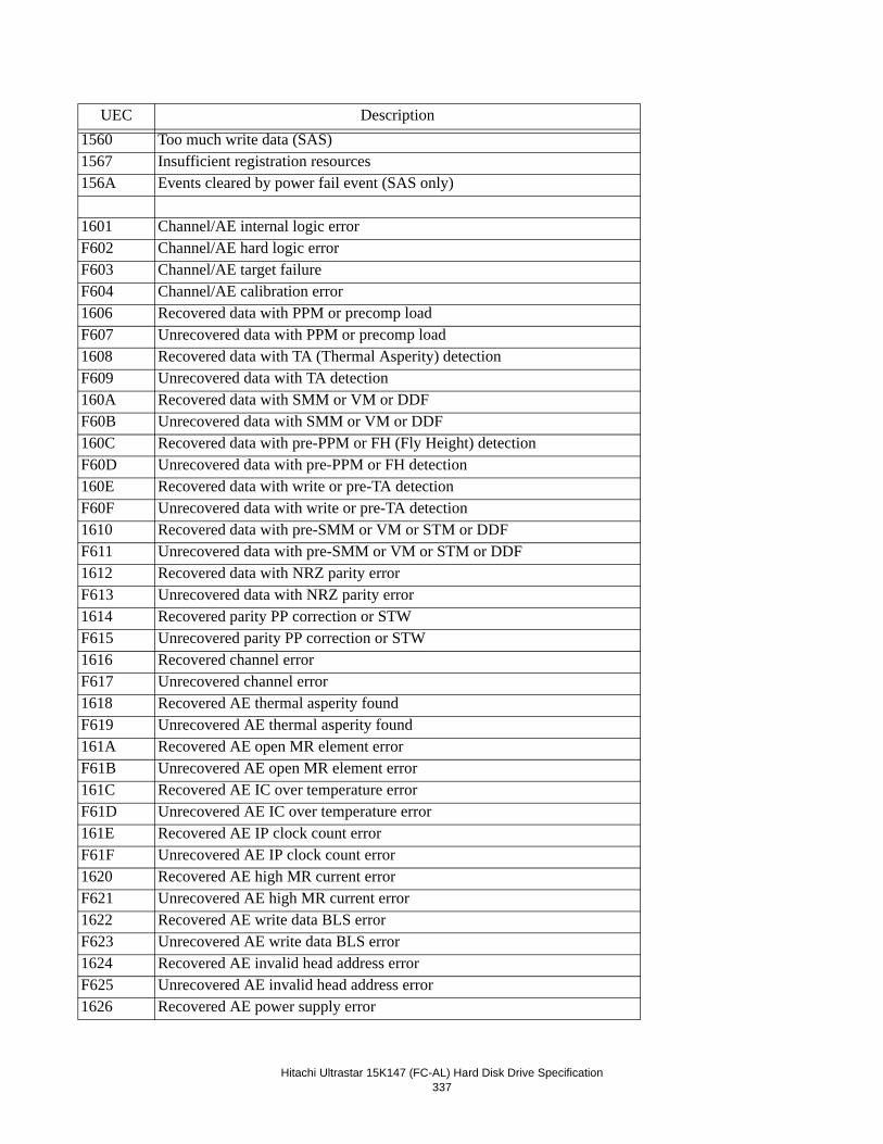
Hitachi Ultrastar 15K147 (FC-AL) Hard Disk Drive Specification337
1560 Too much write data (SAS)1567 Insufficient registration resources156A Events cleared by power fail event (SAS only)
1601 Channel/AE internal logic errorF602 Channel/AE hard logic errorF603 Channel/AE target failureF604 Channel/AE calibration error1606 Recovered data with PPM or precomp loadF607 Unrecovered data with PPM or precomp load1608 Recovered data with TA (Thermal Asperity) detectionF609 Unrecovered data with TA detection160A Recovered data with SMM or VM or DDFF60B Unrecovered data with SMM or VM or DDF160C Recovered data with pre-PPM or FH (Fly Height) detectionF60D Unrecovered data with pre-PPM or FH detection160E Recovered data with write or pre-TA detectionF60F Unrecovered data with write or pre-TA detection1610 Recovered data with pre-SMM or VM or STM or DDFF611 Unrecovered data with pre-SMM or VM or STM or DDF1612 Recovered data with NRZ parity errorF613 Unrecovered data with NRZ parity error1614 Recovered parity PP correction or STWF615 Unrecovered parity PP correction or STW1616 Recovered channel errorF617 Unrecovered channel error1618 Recovered AE thermal asperity foundF619 Unrecovered AE thermal asperity found161A Recovered AE open MR element errorF61B Unrecovered AE open MR element error161C Recovered AE IC over temperature errorF61D Unrecovered AE IC over temperature error161E Recovered AE IP clock count errorF61F Unrecovered AE IP clock count error1620 Recovered AE high MR current errorF621 Unrecovered AE high MR current error1622 Recovered AE write data BLS errorF623 Unrecovered AE write data BLS error1624 Recovered AE invalid head address errorF625 Unrecovered AE invalid head address error1626 Recovered AE power supply error
UEC Description
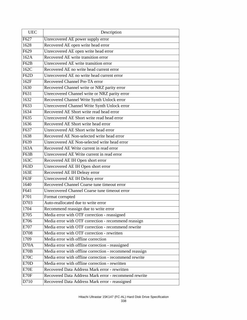
Hitachi Ultrastar 15K147 (FC-AL) Hard Disk Drive Specification338
F627 Unrecovered AE power supply error1628 Recovered AE open write head errorF629 Unrecovered AE open write head error162A Recovered AE write transition errorF62B Unrecovered AE write transition error162C Recovered AE no write head current errorF62D Unrecovered AE no write head current error162F Recovered Channel Pre-TA error1630 Recovered Channel write or NRZ parity errorF631 Unrecovered Channel write or NRZ parity error1632 Recovered Channel Write Synth Unlock errorF633 Unrecovered Channel Write Synth Unlock error1634 Recovered AE Short write read head errorF635 Unrecovered AE Short write read head error1636 Recovered AE Short write head errorF637 Unrecovered AE Short write head error1638 Recovered AE Non-selected write head errorF639 Unrecovered AE Non-selected write head error163A Recovered AE Write current in read errorF63B Unrecovered AE Write current in read error163C Recovered AE IH Open short errorF63D Unrecovered AE IH Open short error163E Recovered AE IH Deleay errorF63F Unrecovered AE IH Deleay error1640 Recovered Channel Coarse tune timeout errorF641 Unrecovered Channel Coarse tune timeout errorF701 Format corruptedD703 Auto-reallocated due to write error1704 Recommend reassign due to write errorE705 Media error with OTF correction - reassignedE706 Media error with OTF correction - recommend reassignE707 Media error with OTF correction - recommend rewriteD708 Media error with OTF correction - rewritten1709 Media error with offline correctionD70A Media error with offline correction - reassignedE70B Media error with offline correction - recommend reassignE70C Media error with offline correction - recommend rewriteE70D Media error with offline correction - rewrittenE70E Recovered Data Address Mark error - rewrittenE70F Recovered Data Address Mark error - recommend rewriteD710 Recovered Data Address Mark error - reassigned
UEC Description
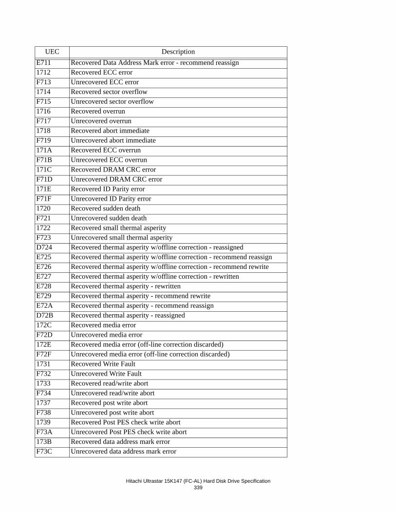
Hitachi Ultrastar 15K147 (FC-AL) Hard Disk Drive Specification339
E711 Recovered Data Address Mark error - recommend reassign1712 Recovered ECC errorF713 Unrecovered ECC error1714 Recovered sector overflowF715 Unrecovered sector overflow1716 Recovered overrunF717 Unrecovered overrun1718 Recovered abort immediateF719 Unrecovered abort immediate171A Recovered ECC overrunF71B Unrecovered ECC overrun171C Recovered DRAM CRC errorF71D Unrecovered DRAM CRC error171E Recovered ID Parity errorF71F Unrecovered ID Parity error1720 Recovered sudden deathF721 Unrecovered sudden death1722 Recovered small thermal asperityF723 Unrecovered small thermal asperityD724 Recovered thermal asperity w/offline correction - reassignedE725 Recovered thermal asperity w/offline correction - recommend reassignE726 Recovered thermal asperity w/offline correction - recommend rewriteE727 Recovered thermal asperity w/offline correction - rewrittenE728 Recovered thermal asperity - rewrittenE729 Recovered thermal asperity - recommend rewriteE72A Recovered thermal asperity - recommend reassignD72B Recovered thermal asperity - reassigned172C Recovered media errorF72D Unrecovered media error172E Recovered media error (off-line correction discarded)F72F Unrecovered media error (off-line correction discarded)1731 Recovered Write FaultF732 Unrecovered Write Fault1733 Recovered read/write abortF734 Unrecovered read/write abort1737 Recovered post write abortF738 Unrecovered post write abort1739 Recovered Post PES check write abortF73A Unrecovered Post PES check write abort173B Recovered data address mark errorF73C Unrecovered data address mark error
UEC Description
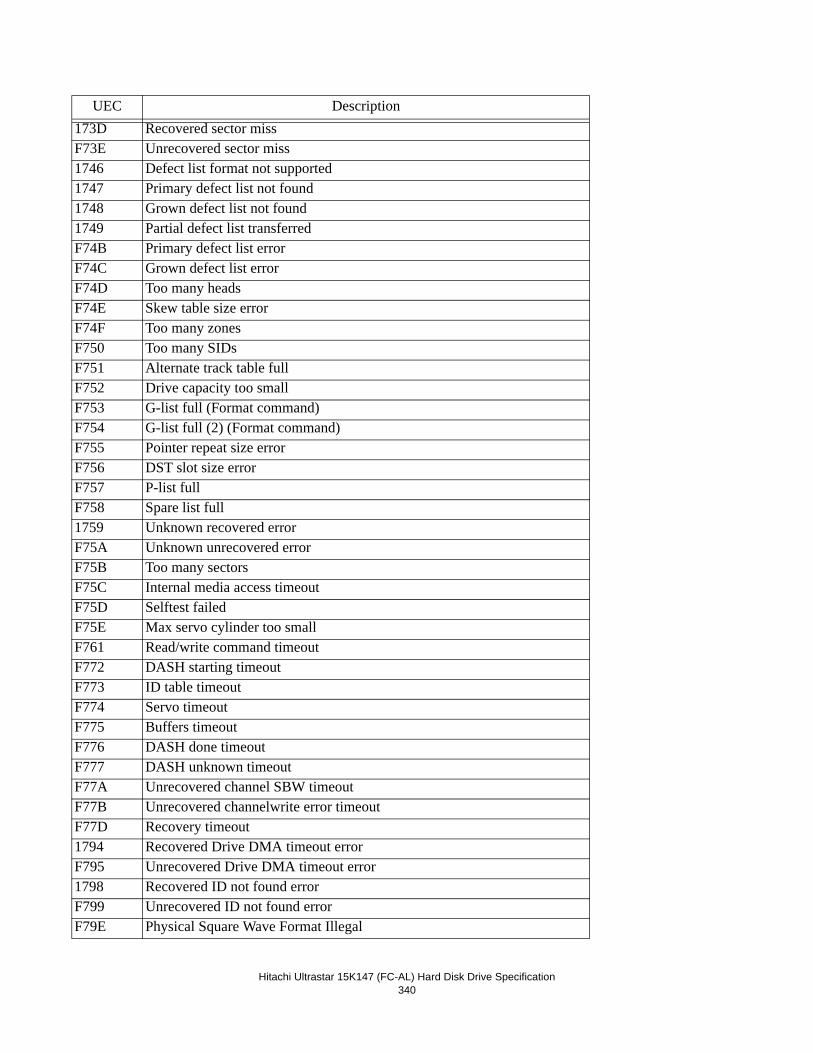
Hitachi Ultrastar 15K147 (FC-AL) Hard Disk Drive Specification340
173D Recovered sector missF73E Unrecovered sector miss1746 Defect list format not supported1747 Primary defect list not found1748 Grown defect list not found1749 Partial defect list transferredF74B Primary defect list errorF74C Grown defect list errorF74D Too many headsF74E Skew table size errorF74F Too many zonesF750 Too many SIDsF751 Alternate track table fullF752 Drive capacity too smallF753 G-list full (Format command)F754 G-list full (2) (Format command)F755 Pointer repeat size errorF756 DST slot size errorF757 P-list fullF758 Spare list full1759 Unknown recovered errorF75A Unknown unrecovered errorF75B Too many sectorsF75C Internal media access timeoutF75D Selftest failedF75E Max servo cylinder too smallF761 Read/write command timeoutF772 DASH starting timeoutF773 ID table timeoutF774 Servo timeoutF775 Buffers timeoutF776 DASH done timeoutF777 DASH unknown timeoutF77A Unrecovered channel SBW timeoutF77B Unrecovered channelwrite error timeoutF77D Recovery timeout1794 Recovered Drive DMA timeout errorF795 Unrecovered Drive DMA timeout error1798 Recovered ID not found errorF799 Unrecovered ID not found errorF79E Physical Square Wave Format Illegal
UEC Description
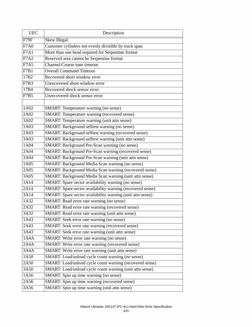
Hitachi Ultrastar 15K147 (FC-AL) Hard Disk Drive Specification341
F79F Skew IllegalF7A0 Customer cylinders not evenly divisible by track spanF7A1 More than one head required for Serpentine formatF7A2 Reserved area cannot be Serpentine formatF7A5 Channel:Course tune timeoutF7B1 Overall Command Timeout17B2 Recovered abort window errorF7B3 Unrecovered abort window error17B4 Recovered shock sensor errorF7B5 Unrecovered shock sensor error
1A02 SMART: Temperature warning (no sense)2A02 SMART: Temperature warning (recovered sense)3A02 SMART: Temperature warning (unit attn sense)1A03 SMART: Background selftest warning (no sense)2A03 SMART: Background selftest warning (recovered sense)3A03 SMART: Background selftest warning (unit attn sense)1A04 SMART: Background Pre-Scan warning (no sense)2A04 SMART: Background Pre-Scan warning (recovered sense)3A04 SMART: Background Pre-Scan warning (unit attn sense)1A05 SMART: Background Media Scan warning (no sense)2A05 SMART: Background Media Scan warning (recovered sense)3A05 SMART: Background Media Scan warning (unit attn sense)1A14 SMART: Spare sector availability warning (no sense)2A14 SMART: Spare sector availability warning (recovered sense)3A14 SMART: Spare sector availability warning (unit attn sense)1A32 SMART: Read error rate warning (no sense)2A32 SMART: Read error rate warning (recovered sense)3A32 SMART: Read error rate warning (unit attn sense)1A43 SMART: Seek error rate warning (no sense)2A43 SMART: Seek error rate warning (recovered sense)3A43 SMART: Seek error rate warning (unit attn sense)1A4A SMART: Write error rate warning (no sense)2A4A SMART: Write error rate warning (recovered sense)3A4A SMART: Write error rate warning (unit attn sense)1A50 SMART: Load/unload cycle count warning (no sense)2A50 SMART: Load/unload cycle count warning (recovered sense)3A50 SMART: Load/unload cycle count warning (unit attn sense)1A56 SMART: Spin up time warning (no sense)2A56 SMART: Spin up time warning (recovered sense)3A56 SMART: Spin up time warning (unit attn sense)
UEC Description
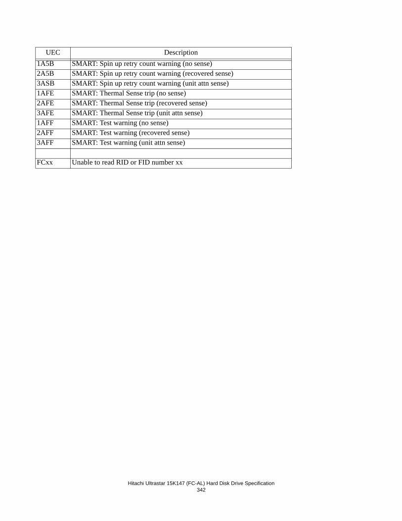
Hitachi Ultrastar 15K147 (FC-AL) Hard Disk Drive Specification342
1A5B SMART: Spin up retry count warning (no sense)2A5B SMART: Spin up retry count warning (recovered sense)3ASB SMART: Spin up retry count warning (unit attn sense)1AFE SMART: Thermal Sense trip (no sense)2AFE SMART: Thermal Sense trip (recovered sense)3AFE SMART: Thermal Sense trip (unit attn sense)1AFF SMART: Test warning (no sense)2AFF SMART: Test warning (recovered sense)3AFF SMART: Test warning (unit attn sense)
FCxx Unable to read RID or FID number xx
UEC Description
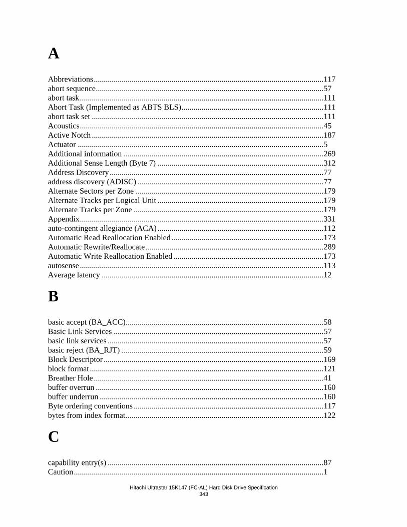
Hitachi Ultrastar 15K147 (FC-AL) Hard Disk Drive Specification343
AAbbreviations...................................................................................................................117abort sequence..................................................................................................................57abort task..........................................................................................................................111Abort Task (Implemented as ABTS BLS).......................................................................111abort task set ....................................................................................................................111Acoustics..........................................................................................................................45Active Notch ....................................................................................................................187Actuator ...........................................................................................................................5Additional information ....................................................................................................269Additional Sense Length (Byte 7) ...................................................................................312Address Discovery ...........................................................................................................77address discovery (ADISC) .............................................................................................77Alternate Sectors per Zone ..............................................................................................179Alternate Tracks per Logical Unit ...................................................................................179Alternate Tracks per Zone ...............................................................................................179Appendix..........................................................................................................................331auto-contingent allegiance (ACA) ...................................................................................112Automatic Read Reallocation Enabled ............................................................................173Automatic Rewrite/Reallocate .........................................................................................289Automatic Write Reallocation Enabled ...........................................................................173autosense ..........................................................................................................................113Average latency ...............................................................................................................12
Bbasic accept (BA_ACC)...................................................................................................58Basic Link Services .........................................................................................................57basic link services ............................................................................................................57basic reject (BA_RJT) .....................................................................................................59Block Descriptor ..............................................................................................................169block format .....................................................................................................................121Breather Hole ...................................................................................................................41buffer overrun ..................................................................................................................160buffer underrun ................................................................................................................160Byte ordering conventions ...............................................................................................117bytes from index format...................................................................................................122
Ccapability entry(s) ............................................................................................................87Caution.............................................................................................................................1
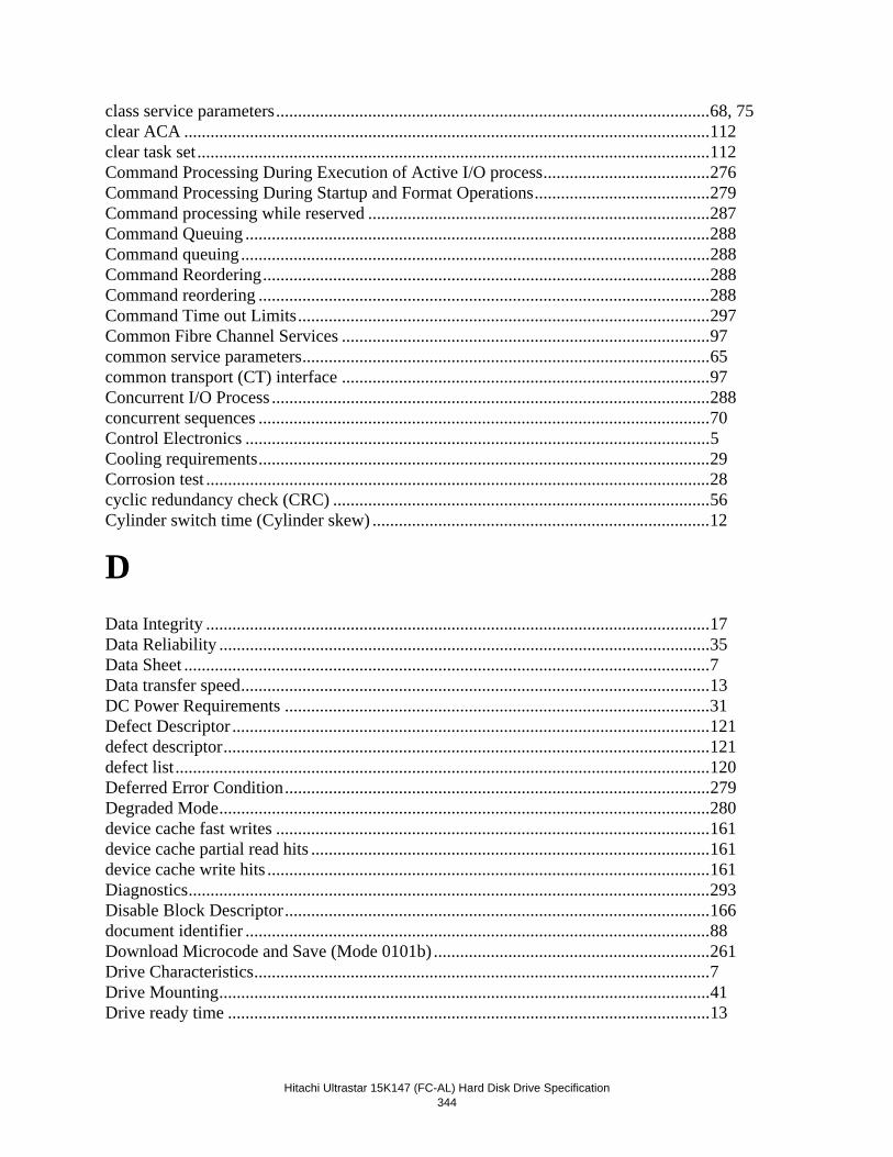
Hitachi Ultrastar 15K147 (FC-AL) Hard Disk Drive Specification
344
class service parameters...................................................................................................68, 75clear ACA ........................................................................................................................112clear task set.....................................................................................................................112Command Processing During Execution of Active I/O process......................................276Command Processing During Startup and Format Operations........................................279Command processing while reserved ..............................................................................287Command Queuing ..........................................................................................................288Command queuing...........................................................................................................288Command Reordering......................................................................................................288Command reordering .......................................................................................................288Command Time out Limits..............................................................................................297Common Fibre Channel Services ....................................................................................97common service parameters.............................................................................................65common transport (CT) interface ....................................................................................97Concurrent I/O Process ....................................................................................................288concurrent sequences .......................................................................................................70Control Electronics ..........................................................................................................5Cooling requirements.......................................................................................................29Corrosion test ...................................................................................................................28cyclic redundancy check (CRC) ......................................................................................56Cylinder switch time (Cylinder skew) .............................................................................12
DData Integrity ...................................................................................................................17Data Reliability ................................................................................................................35Data Sheet ........................................................................................................................7Data transfer speed...........................................................................................................13DC Power Requirements .................................................................................................31Defect Descriptor .............................................................................................................121defect descriptor...............................................................................................................121defect list..........................................................................................................................120Deferred Error Condition.................................................................................................279Degraded Mode................................................................................................................280device cache fast writes ...................................................................................................161device cache partial read hits ...........................................................................................161device cache write hits .....................................................................................................161Diagnostics.......................................................................................................................293Disable Block Descriptor.................................................................................................166document identifier ..........................................................................................................88Download Microcode and Save (Mode 0101b) ...............................................................261Drive Characteristics........................................................................................................7Drive Mounting................................................................................................................41Drive ready time ..............................................................................................................13
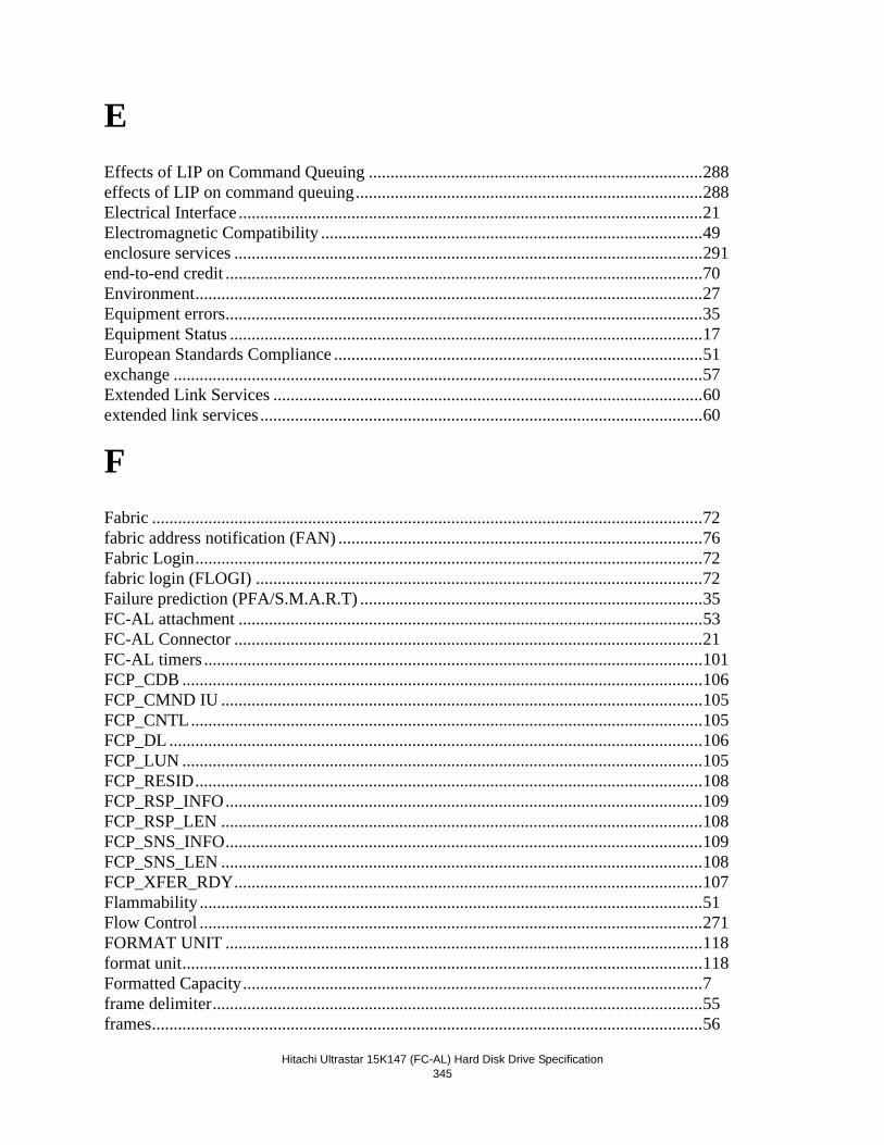
Hitachi Ultrastar 15K147 (FC-AL) Hard Disk Drive Specification345
EEffects of LIP on Command Queuing .............................................................................288effects of LIP on command queuing................................................................................288Electrical Interface ...........................................................................................................21Electromagnetic Compatibility ........................................................................................49enclosure services ............................................................................................................291end-to-end credit ..............................................................................................................70Environment.....................................................................................................................27Equipment errors..............................................................................................................35Equipment Status .............................................................................................................17European Standards Compliance .....................................................................................51exchange ..........................................................................................................................57Extended Link Services ...................................................................................................60extended link services ......................................................................................................60
FFabric ...............................................................................................................................72fabric address notification (FAN) ....................................................................................76Fabric Login.....................................................................................................................72fabric login (FLOGI) .......................................................................................................72Failure prediction (PFA/S.M.A.R.T) ...............................................................................35FC-AL attachment ...........................................................................................................53FC-AL Connector ............................................................................................................21FC-AL timers ...................................................................................................................101FCP_CDB ........................................................................................................................106FCP_CMND IU ...............................................................................................................105FCP_CNTL......................................................................................................................105FCP_DL ...........................................................................................................................106FCP_LUN ........................................................................................................................105FCP_RESID.....................................................................................................................108FCP_RSP_INFO..............................................................................................................109FCP_RSP_LEN ...............................................................................................................108FCP_SNS_INFO..............................................................................................................109FCP_SNS_LEN ...............................................................................................................108FCP_XFER_RDY............................................................................................................107Flammability ....................................................................................................................51Flow Control ....................................................................................................................271FORMAT UNIT ..............................................................................................................118format unit........................................................................................................................118Formatted Capacity..........................................................................................................7frame delimiter.................................................................................................................55frames...............................................................................................................................56
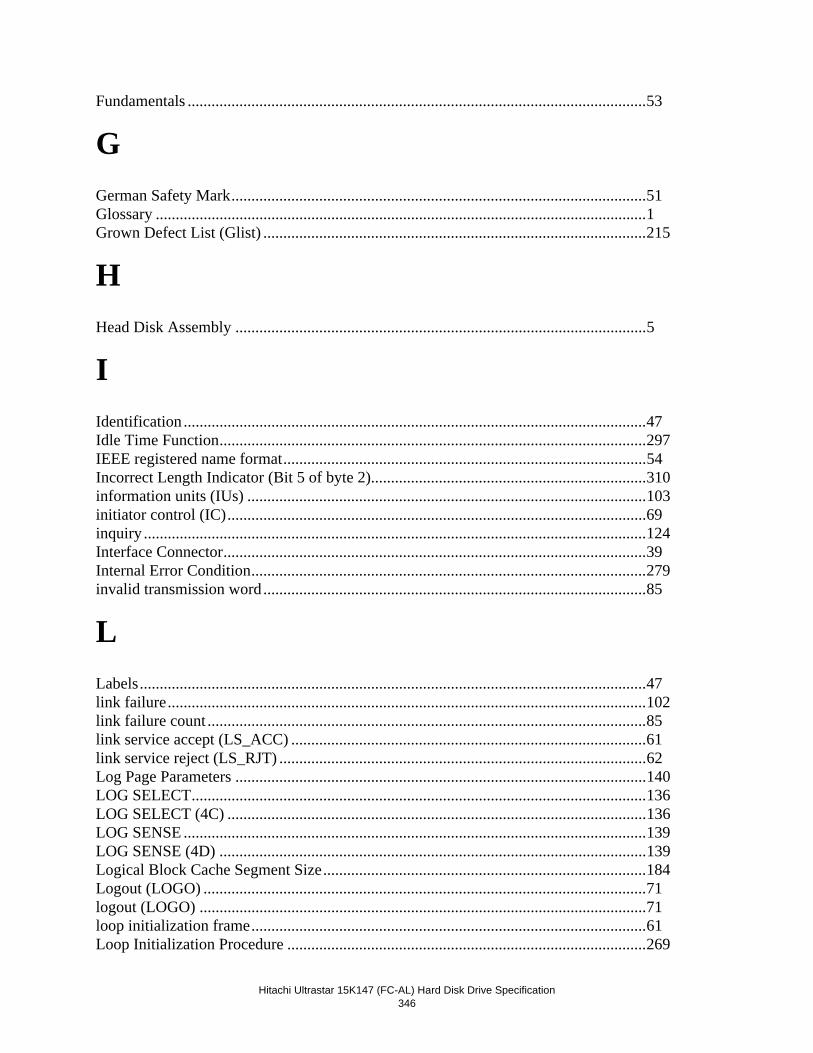
Hitachi Ultrastar 15K147 (FC-AL) Hard Disk Drive Specification
346
Fundamentals ...................................................................................................................53
GGerman Safety Mark........................................................................................................51Glossary ...........................................................................................................................1Grown Defect List (Glist) ................................................................................................215
HHead Disk Assembly .......................................................................................................5
IIdentification ....................................................................................................................47Idle Time Function...........................................................................................................297IEEE registered name format...........................................................................................54Incorrect Length Indicator (Bit 5 of byte 2).....................................................................310information units (IUs) ....................................................................................................103initiator control (IC).........................................................................................................69inquiry ..............................................................................................................................124Interface Connector..........................................................................................................39Internal Error Condition...................................................................................................279invalid transmission word................................................................................................85
LLabels...............................................................................................................................47link failure........................................................................................................................102link failure count ..............................................................................................................85link service accept (LS_ACC) .........................................................................................61link service reject (LS_RJT) ............................................................................................62Log Page Parameters .......................................................................................................140LOG SELECT..................................................................................................................136LOG SELECT (4C) .........................................................................................................136LOG SENSE ....................................................................................................................139LOG SENSE (4D) ...........................................................................................................139Logical Block Cache Segment Size.................................................................................184Logout (LOGO) ...............................................................................................................71logout (LOGO) ................................................................................................................71loop initialization frame...................................................................................................61Loop Initialization Procedure ..........................................................................................269
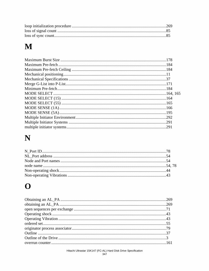
Hitachi Ultrastar 15K147 (FC-AL) Hard Disk Drive Specification347
loop initialization procedure ............................................................................................269loss of signal count ..........................................................................................................85loss of sync count.............................................................................................................85
MMaximum Burst Size .......................................................................................................178Maximum Pre-fetch .........................................................................................................184Maximum Pre-fetch Ceiling ............................................................................................184Mechanical positioning....................................................................................................11Mechanical Specifications ...............................................................................................37Merge G-List into P-List..................................................................................................171Minimum Pre-fetch..........................................................................................................184MODE SELECT ..............................................................................................................164, 165MODE SELECT (15) ......................................................................................................164MODE SELECT (55) ......................................................................................................165MODE SENSE (1A) ........................................................................................................166MODE SENSE (5A) ........................................................................................................195Multiple Initiator Environment ........................................................................................292Multiple Initiator Systems ...............................................................................................291multiple initiator systems.................................................................................................291
NN_Port ID.........................................................................................................................78NL_Port address ..............................................................................................................54Node and Port names .......................................................................................................54node name ........................................................................................................................54, 78Non-operating shock........................................................................................................44Non-operating Vibrations ................................................................................................43
OObtaining an AL_PA .......................................................................................................269obtaining an AL_PA ........................................................................................................269open sequences per exchange ..........................................................................................71Operating shock ...............................................................................................................43Operating Vibration .........................................................................................................43ordered set........................................................................................................................55originator process associator............................................................................................79Outline .............................................................................................................................37Outline of the Drive .........................................................................................................3overrun counter ................................................................................................................161
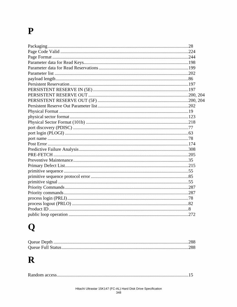
Hitachi Ultrastar 15K147 (FC-AL) Hard Disk Drive Specification
348
PPackaging.........................................................................................................................28Page Code Valid ..............................................................................................................224Page Format .....................................................................................................................244Parameter data for Read Keys..........................................................................................198Parameter data for Read Reservations .............................................................................199Parameter list ...................................................................................................................202payload length..................................................................................................................86Persistent Reservation......................................................................................................197PERSISTENT RESERVE IN (5E) ..................................................................................197PERSISTENT RESERVE OUT ......................................................................................200, 204PERSISTENT RESERVE OUT (5F) ..............................................................................200, 204Persistent Reserve Out Parameter list ..............................................................................202Physical Format ...............................................................................................................19physical sector format ......................................................................................................123Physical Sector Format (101b) ........................................................................................218port discovery (PDISC) ...................................................................................................77port login (PLOGI) ..........................................................................................................63port name .........................................................................................................................78Post Error .........................................................................................................................174Predictive Failure Analysis ..............................................................................................308PRE-FETCH ....................................................................................................................205Preventive Maintenance...................................................................................................35Primary Defect List..........................................................................................................215primitive sequence ...........................................................................................................55primitive sequence protocol error ....................................................................................85primitive signal ................................................................................................................55Priority Commands ..........................................................................................................287Priority commands ...........................................................................................................287process login (PRLI) ........................................................................................................78process logout (PRLO) ....................................................................................................82Product ID........................................................................................................................8public loop operation .......................................................................................................272
QQueue Depth ....................................................................................................................288Queue Full Status.............................................................................................................288
RRandom access.................................................................................................................15
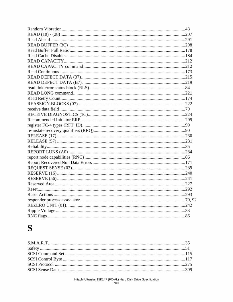
Hitachi Ultrastar 15K147 (FC-AL) Hard Disk Drive Specification349
Random Vibration............................................................................................................43READ (10) - (28) .............................................................................................................207Read Ahead......................................................................................................................291READ BUFFER (3C) ......................................................................................................208Read Buffer Full Ratio.....................................................................................................178Read Cache Disable .........................................................................................................184READ CAPACITY..........................................................................................................212READ CAPACITY command.........................................................................................212Read Continuous..............................................................................................................173READ DEFECT DATA (37)...........................................................................................215READ DEFECT DATA (B7) ..........................................................................................219read link error status block (RLS)....................................................................................84READ LONG command..................................................................................................221Read Retry Count.............................................................................................................174REASSIGN BLOCKS (07) .............................................................................................222receive data field ..............................................................................................................70RECEIVE DIAGNOSTICS (1C).....................................................................................224Recommended Initiator ERP ...........................................................................................299register FC-4 types (RFT_ID)..........................................................................................99re-instate recovery qualifiers (RRQ)................................................................................90RELEASE (17) ................................................................................................................230RELEASE (57) ................................................................................................................231Reliability.........................................................................................................................35REPORT LUNS (A0) ......................................................................................................234report node capabilities (RNC) ........................................................................................86Report Recovered Non Data Errors .................................................................................171REQUEST SENSE (03)...................................................................................................239RESERVE (16) ................................................................................................................240RESERVE (56) ................................................................................................................241Reserved Area..................................................................................................................227Reset.................................................................................................................................292Reset Actions ...................................................................................................................293responder process associator............................................................................................79, 92REZERO UNIT (01)........................................................................................................242Ripple Voltage .................................................................................................................33RNC flags ........................................................................................................................86
SS.M.A.R.T........................................................................................................................35Safety ...............................................................................................................................51SCSI Command Set .........................................................................................................115SCSI Control Byte ...........................................................................................................117SCSI Protocol ..................................................................................................................275SCSI Sense Data ..............................................................................................................309
Hitachi Ultrastar 15K147 (FC-AL) Hard Disk Drive Specification
350
SCSI Sense Data Format..................................................................................................309SCSI Status Byte..............................................................................................................267SCSI Status Byte Reporting.............................................................................................275SCSI-FCP.........................................................................................................................103Sectors per Track .............................................................................................................180SEEK (10) - (2B) .............................................................................................................243SEEK (6) - (0B) ...............................................................................................................243seek counter .....................................................................................................................160Seek errors .......................................................................................................................35seeks.................................................................................................................................160Segmented Caching .........................................................................................................291SEND DIAGNOSTIC (1D) .............................................................................................244sense data .........................................................................................................................291Sense Data Description ....................................................................................................310Sense Key (Bit 3 - 0 of byte 2) ........................................................................................311SenseData.........................................................................................................................309sequence...........................................................................................................................56Service Action..................................................................................................................197, 201Size Enable ......................................................................................................................183Sound power levels ..........................................................................................................45Spindle stop time .............................................................................................................13START STOP UNIT (1B) ...............................................................................................249Start/Stop Cycles..............................................................................................................35Storage requirements .......................................................................................................28Storage time .....................................................................................................................28Summary ..........................................................................................................................203Swept Sine Vibration .......................................................................................................43SYNCHRONIZE CACHE (35) .......................................................................................250
Ttarget reset........................................................................................................................112Task Attributes.................................................................................................................109Task Management functions ............................................................................................110task management functions..............................................................................................103Temperature and humidity...............................................................................................27Temperature Threshold....................................................................................................172terminate task ...................................................................................................................112Terminology.....................................................................................................................103TEST UNIT READY (00) ...............................................................................................251third party N_Port ID.......................................................................................................92third party originator process associator ..........................................................................92third party process logout (TPRLO) ................................................................................91Throughput.......................................................................................................................14Track Skew Factor ...........................................................................................................180
Hitachi Ultrastar 15K147 (FC-AL) Hard Disk Drive Specification351
Tracks per Zone ...............................................................................................................180Transfer Block .................................................................................................................173transmission character......................................................................................................55Type .................................................................................................................................201
UUEC list............................................................................................................................331UL and CSA Standard Conformity..................................................................................51underrun counter ..............................................................................................................161Unit Attention Condition .................................................................................................305unit attention condition ....................................................................................................277
Vvendor identifier...............................................................................................................86vendor unique information...............................................................................................86Verify ...............................................................................................................................307VERIFY (2F) ...................................................................................................................252Vibration and Shock ........................................................................................................43VU information length (VU_Len) ...................................................................................86
Wword .................................................................................................................................55WRITE (10) - (2A) ..........................................................................................................255WRITE (6) - (0A) ............................................................................................................254WRITE AND VERIFY (2E)............................................................................................256, 258WRITE BUFFER (3B) ....................................................................................................262Write Buffer Empty Ratio................................................................................................178Write Cache .....................................................................................................................289Write Cache Enable .........................................................................................................183WRITE LONG (3F).........................................................................................................263Write Retention Priority...................................................................................................184Write Retry Count............................................................................................................174WRITE SAME (41) .........................................................................................................264
Zzero seeks .........................................................................................................................160

Hitachi Ultrastar 15K147 (FC-AL) Hard Disk Drive Specification
352
© Copyright Hitachi Global Storage Technologies
Hitachi Global Storage Technologies5600 Cottle RoadSan Jose, CA 95193Produced in the United States
03/06
All rights reserved Ultrastar™ is a trademark ofHitachi Global Storage Technologies.
Microsoft, Windows XP, and Windows are trademarks of Microsoft Corporation in the United States, other countries, or both.
Other product names are trademarks or registered trade-marks of their respective companies. References in this publication to Hitachi Global Storage Technologies products, programs or services do not imply that Hitachi Global Storage Technologies intends to make these available in all countries in which Hitachi Global Storage Technologies operates.
Product information is provided for information pur-poses only and does not constitute a warranty. Information is true as of the date of publication and is subject to change. Actual results may vary. This publication is for general guidance only. Photo-graphs may show design models.
07 March 2006