operating manual - gilson co
TRANSCRIPT

OPERATING MANUAL
Gilson Economy 8in Sieve ShakersSS-15 & SS-15D
Rev: 07/11/2016
PHONE: 800-444-1508 P.O. Box 200, Lewis Center, Ohio 43035-0200 FAX: 800-255-5314 740-548-7298 E-mail: [email protected] Website: www.globalgilson.com 740-548-5314
SS-15 SS-15D
Gilson Company, Inc. Gilson Economy 8in Sieve Shaker: SS-15
Page 2
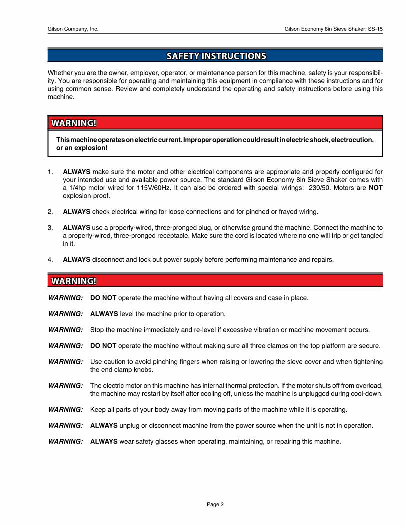
SAFETY INSTRUCTIONS
Whether you are the owner, employer, operator, or maintenance person for this machine, safety is your responsibil-ity. You are responsible for operating and maintaining this equipment in compliance with these instructions and for using common sense. Review and completely understand the operating and safety instructions before using this machine.
WARNING!
This machine operates on electric current. Improper operation could result in electric shock, electrocution, or an explosion!
1. ALWAYS make sure the motor and other electrical components are appropriate and properly configured for your intended use and available power source. The standard Gilson Economy 8in Sieve Shaker comes with a 1/4hp motor wired for 115V/60Hz. It can also be ordered with special wirings: 230/50. Motors are NOT explosion-proof.
2. ALWAYS check electrical wiring for loose connections and for pinched or frayed wiring.
3. ALWAYS use a properly-wired, three-pronged plug, or otherwise ground the machine. Connect the machine to a properly-wired, three-pronged receptacle. Make sure the cord is located where no one will trip or get tangled in it.
4. ALWAYS disconnect and lock out power supply before performing maintenance and repairs.
WARNING!
WARNING: DO NOT operate the machine without having all covers and case in place.
WARNING: ALWAYS level the machine prior to operation.
WARNING: Stop the machine immediately and re-level if excessive vibration or machine movement occurs.
WARNING: DO NOT operate the machine without making sure all three clamps on the top platform are secure.
WARNING: Use caution to avoid pinching fingers when raising or lowering the sieve cover and when tightening the end clamp knobs.
WARNING: The electric motor on this machine has internal thermal protection. If the motor shuts off from overload, the machine may restart by itself after cooling off, unless the machine is unplugged during cool-down.
WARNING: Keep all parts of your body away from moving parts of the machine while it is operating.
WARNING: ALWAYS unplug or disconnect machine from the power source when the unit is not in operation.
WARNING: ALWAYS wear safety glasses when operating, maintaining, or repairing this machine.

Gilson Company, Inc. Gilson Economy 8in Sieve Shaker: SS-15
Page 3
Table of Contents
Page
Safety Instructions 2 Table of Contents 3 1.0 Unpacking & Set-Up 4
2.0 Operating Instructions 4 3.0 Maintenance 5 3.1 Cleaning the Unit 5 3.2 Drive Belt 5 3.3 Motor 5 3.4a Spring Wound Timer 6 3.4b Digital Timer 6 3.5 Main Shaft 6 3.6 Reassembly of the Unit 6
4.0 Troubleshooting 6
5.0 Sieving Accuracy 6
6.0 Parts Diagram 8 6.1 SS-15 8
7.0 Parts List 9 7.1 SS-15 Parts List 9
8.0 Additional Information 10 8.1 Gilson Test Sieves 10 8.2 Test Sieve & Screen Tray Verification & Services 11 8.3 8in Diameter ASTM Test Sieves 13
Gilson Company, Inc. Gilson Economy 8in Sieve Shaker: SS-15
Page 4
1.0 UNPACKING & SET-UP:
NOTE: DO NOT plug in or otherwise connect the SS-15 to a power source until this initial inspection is complete. Damage claims MUST be filed with shipping carrier within ten days. The SS-15 is ready to operate as shipped.
1.1 The SS-15 weighs approximately 52lb (24kg). Use appropriate equipment and manpower to uncrate the sieve shaker. Wear safety glasses and work gloves.
1.2 Open the top of the carton and lift the SS-15 out by the stabilizer bar. If at all possible, DO NOT cut away the carton since you will need it if the machine must be returned. If you do not have equipment for lifting the machine, you will have to cut away the carton. Set the unit on a solid, substantial surface, and inspect it for shipping damage and for loose or missing parts or documents.
1.3 Inspect the SS-15 for shipping damages. Damage claims should be noted on carrier's bill of lading before signing for acceptance. It is the recipient's responsibility to immediately file damage claims with the carrier.
Check that the unit is wired to match your power sup-ply. The standard SS-15 comes with a 1/4hp, 115V, 60-cycle motor.
1.4 On the bottom of the unit are four small rubber feet. These may be removed to use the base holes for permanent mounting if desired. Use appropriately sized mounting screws and bolts 5/16in if you plan to secure the unit to the table. Turn the machine upright on the table. Permanently bolting the machine may cause premature wear of parts.
2.0 OPERATING INSTRUCTIONS:
Please read understand all safety and operating instruc-tions for the Gilson Economy 8in Sieve Shaker before putting it into service.
2.1 Make sure that the SS-15 is unplugged from the power supply before beginning operation.
2.2 Rotate EZ-Clamp knobs so buttons face inward. While holding the knobs, push both buttons in firmly and slide the cover up to the desired position. When you release the buttons, the cover assembly will remain in position, allowing insertion of the sieve stack.
2.3 Load your sieve stack onto the sieve platform of the SS-15, insuring it is centered on the platform.
2.4 Turn the E-Z-Clamp knobs so buttons face inward, depress the buttons and slide the cover assembly down firmly on top of the sieve stack.
2.5 Tighten the knobs by turning them clockwise until the lid feels securely clamped. If the knobs “pop”, they were turned too far. Simply retighten to again secure the cover assembly on the stack.
2.6 Plug in the SS-15 after confirming your power supply is configured correctly and grounded properly. Set the timer and turn on the machine.
2.6.1 If your Gilson 8in/12in Sieve Shaker comes with a spring-wound timer, it is a model SS-15, and the timer serves as the on/off switch as well as test timer. The timer ring stop may be rotated and set to exactly repeat test times by tightening the slotted knurled clamp screw. The stop peg should be set for greater than five minutes.
NOTE: The main device that the timer controls may be restricted to operating on a more limited electrical supply range. Check the device carefully to insure compatibility with your electrical supply.
2.6.2 If your machine is equipped with a digital timer it is a model SS-15D
NOTE: ALWAYS disconnect the unit after use.
NOTE: The main device that the timer controls may be restricted to operating on a more limited electrical supply range. Check the device carefully to insure compatibility with your electrical supply.
Current timer mode is indicated by the four red LED’s on the timer face:
A=MMSS (99min:59sec x 1 second) B=HHMM (99hr:59min x 1 minute) C-SSSS (9999sec x 1 second) D=MMMM (9999min x 1 minute)

Gilson Company, Inc. Gilson Economy 8in Sieve Shaker: SS-15
Page 5
(H is for hours, M for minutes, and S for seconds.) To adjust the timer mode, press and hold both <UP> and <DOWN> keys at the same time until the display shows the mode. Once the mode letters are displayed, press <UP> or <DOWN> to change modes. Press <START/STOP> to accept new mode.
To set the run time, press either <UP> or <DOWN>. The first digit on the right hand will flash in half-second intervals. Press either arrow key to adjust to the de-sired value. To enter the displayed digit and move to the next, press <START/STOP>. Once the last digit on the left is entered, the timer is ready to start.
Press <START/STOP> to initiate the current run program. Once running, pressing <START/STOP> again will pause the timer with the current amount of time remaining on screen. When allowed to time-out, the timer beeps and displays DONE. Press any key to continue. Setting and Mode values are saved automatically.
3.0 MAINTENANCE:
Before performing maintenance or repairs on the sieve shaker, ALWAYS read and understand the safety, operat-ing, and maintenance instructions.
ALWAYS disconnect the SS-15 from its power before performing maintenance or repair. The SS-15's motor has internal thermal protection which may cause it to restart automatically.
Send back your unit's registration card. This card regis-ters the serial number in Gilson's master file and assures supply of proper parts when service is required. Provide this serial number whenever ordering replacement parts.
3.1 Cleaning the Unit:
3.1.1 Clean the unit AT LEAST once a year. It is de-signed to give consistent results. Dirt can affect test results. An appropriate cleaning schedule for your unit depends on the frequency of use, exposure to dirt, and sample makeup.
3.1.2 Clean beneath the unit at least annually. Take care not to introduce cleaning agents into the timer or the motor. If a thorough cleaning is required, the motor and timer must first be removed. See below.
3.1.3 To perform maintenance or repairs, or to inspect the internal parts of the SS-15, place the unit on either of its sides or on its back as appropriate. Make sure to prop up the machine as necessary to avoid damage to the power cord or platform.
3.2 Drive Belt:
3.2.1 Periodically check drive belt for wear, tension, and alignment. A worn, loose, tight, or misaligned drive belt can affect the operation of your SS-15. The belt should be snug: neither too tight nor too loose. A snug fit assures longer life, less bearing wear, and quieter operation than a belt which is too tight. A loose belt may cause the unit to run too slowly or to slip. The drive belt should deflect 1/64 of the value of the space of the pulleys. The pulleys should be aligned to avoid excessive edge wear on the belt.
3.2.2 To adjust or replace the belt, lay the unit on its left side, making sure not to pinch the electrical cord. Loosen the four Motor Mounting Bolts (#26) on the top of the outer case (see Parts Diagram). Move the motor up or down to adjust tension in the drive belt. Use a straight edge to maintain pulley alignment. If you must adjust the belt past the end of the slots to get proper snugness, replace the belt. NEVER force or pry the belt over the pulley flanges.
3.3 Motor:
3.3.1 Apply a few drops of oil to the motor and bearings at least once a year.
3.3.2 To remove the motor, lay the unit on back or left side so that it will fall away from other internal parts when the mounting bolts are removed. Remove the four motor mounting bolts on top of the outer case. As the motor loosens remove the drive belt. Remove the motor terminal cover plate which is held with two screws located where the power and timer cords enter the motor.
3.3.3 Disconnect the power and timer wire terminals, noting where each is attached, loosen the cord and remove the wires from the motor terminal box. The motor is now completely free. Remove motor belt pulley by loosening the set screw.
3.3.4 Have the motor cleaned or overhauled by a trained electric motor repair person. Replacement motors are available from Gilson. To install the motor, reverse the steps of the procedure described previously. Make sure that both pulleys are aligned and that the belt is properly tensioned.
Gilson Company, Inc. Gilson Economy 8in Sieve Shaker: SS-15
Page 6
4.0 TROUBLESHOOTING:
Unit Fails to Operate:First establish that power is being delivered to it. The wall outlet should be tested with a meter or other device for evaluating current.
Check the Timer to make sure it is functioning properly. If the Timer is not functioning, order a new one from Gilson.
Next, loosen the Motor Mounting Bolts and remove the Drive Belt.
If the motor still will not run, continue with the Motor re-moval procedure described in the Maintenance Section. To gain access to the motor terminal cover plate, remove the plate and test for power cord continuity. If the power cord is not at fault, then repair or replace the motor.
Drive Shaft Binding is Evident:Remove and inspect the bearings, bushings, and other components attached to the Main Shaft. To disassemble the drive shaft components, see the procedure outlined in the Maintenance Section. Note belt alignment and component spacing for reassembly.
Unit Operates but is Excessively Noisy:Excessive noise may come from loose sieve retainer clamps, bolts, nuts, egg-shaping of bushings, or worn bearings. Always check for loose nuts, bolts and clamps before disassembling the SS-15's components. Replace the frame guide bushing (#21) when the bushing makes a flopping sound.
5.0 SIEVING ACCURACY:
Accurate sieving is achieved by applying a proper com-bination of equipment, including standard quality sieves, and sieving technique.
The following suggestions will help improve test results:
5.1 Determine suitable test times for each type of sample. One method is to shake each sieve singly with a pan (by machine or by hand) for an additional minute fol-lowing a test. If a significant percentage, say 1—2%, of the retained materials passes with the added sieving time, test time should be increased.
5.2 Use only sample types within the design range of the test apparatus. The SS-15 has an approximate design
3.4a Spring Wound Timer:
To remove the Timer, loosen both Timer terminals, and pull off the leads. Remove both screws from the retain-ing bracket on the back of the timer. This should free the timer unit.
3.4b Digital Timer:
To remove the digital timer, disconnect power from unit by unplugging machine from power source. Then disconnect wiring harness connection from motor and power supply by pulling connection apart, being careful not to discon-nect sections (or wires) so they remain properly oriented to easily reconnect.
Loosen and remove nuts from back of plastic box, this will now allow you to remove the timer out the front of the machine and the box to inside of machine.
3.5 Main Shaft:
3.5.1 To remove the Main Shaft (#1) and attached subunits, lay the unit on either side (but NOT on its back) and loosen the drive belt following the instructions in Section 3.2., and remove it. Loosen the four set screws touching the Main Shaft: Main Shaft Pulley (#11), Counterweight (#10), Eccentric (#9), and Main Shaft Collar (#3). Remove the Yoke Bushing Shoulder Bolts (#8). This frees the Main Shaft to be pushed to the right toward the front of the unit creating enough space to remove the Main Shaft Pulley (#11), Counterweight (#10), Eccentric (#9), Eccentric Bearing (#5), Yoke Bearing Collar (#6), and Main Shaft Collar (#4) respectively.
3.5.2 The Main Shaft can be moved to the left (to the rear of the outer case) if only a few components on the right side are being serviced. Notice the spacing as each piece is removed. Inspect each disassembled piece for wear, especially the Main Shaft Bushing (#2), Main Shaft (#1), and Eccentric (#9). Any signs of wear or egg-shaping warrant the part's replacement. Order replacement parts from Gilson by name and key number.
3.6 Reassembly of the Unit:
To reassemble the unit, follow the above described se-quence in reverse, taking caution to reestablish drive belt alignment and spacing of components. Use the SS-15 Parts Diagram as a guide.

Gilson Company, Inc. Gilson Economy 8in Sieve Shaker: SS-15
Page 7
range of No.4—No.50 sieve sizes, but acceptable results may be possible over a wider range depend-ing on sample specific gravity, particle shape, and fraction of sample that is outside the normal design range.
5.3 DO NOT overload sieves. Maximum loading at completion of sieving is about 132cc on individual 8in (203mm) diameter sieves in the design range. If the loading is greater, either reduce the starting sample size or insert an extra intermediate sieve to reduce loading on the critical sieve.
5.4 Check sieves periodically to ensure that the wire cloth is in accordance with ASTM E11 standards. A Gilson's TSA-175 Pocket Magnifier is useful for spot checking for flaws and for mesh size identification. Calibration beads are also available for precision work where effective sieve opening ratings are determined for each sieve rather than using the nominal size ratings.

Gilson Company, Inc. Gilson Economy 8in Sieve Shaker: SS-15
Page 8
© 2016 GILSON SCREEN INCORPORATED. ALL RIGHTS RESERVED. THIS DOCUMENT IS THE PROPERTY OFGILSON SCREEN INCORPORATED, AND IS LICENSED UNDER A CONFIDENTIAL RELATIONSHIP FOR ASPECIFIC PURPOSE. RECIPIENT AGREES BY RECEIPT HEREOF NOT TO SUPPLY OR DISCLOSE ANYINFORMATION CONTAINED IN THIS DOCUMENT TO ANY OUTSIDE PARTIES WITHOUT GILSON SCREENINCORPORATED’S WRITTEN PERMISSION.
6.0 PARTS DIAGRAM:
6.1 SS-15
SS-15 Parts Diagram
42
41
21
43
44
36
37
40
38
39
35
41
42
12
7
8
27
2
11
104
9
6
5
3
1
2
24
25
23
28D
22
26
28 Spring-Wound Timer
Digital Timer
Parts 5,6 and 9 are factory-assembled and must be
ordered together.
Gilson Company, Inc. Gilson Economy 8in Sieve Shaker: SS-15
Page 9
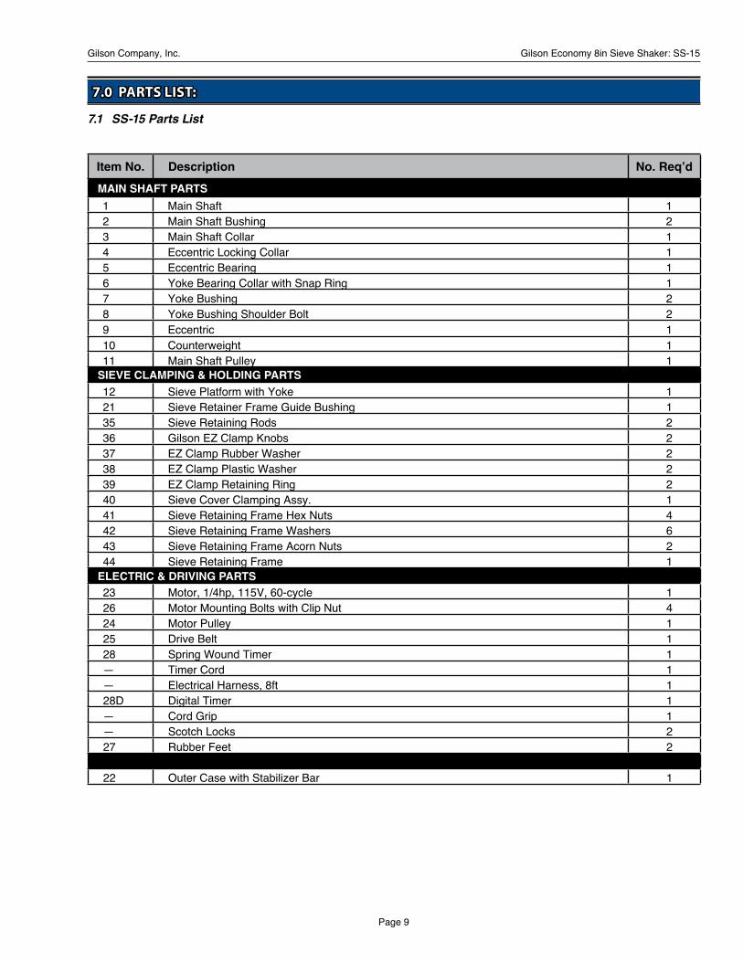
7.0 PARTS LIST:
7.1 SS-15 Parts List
Item No. Description No. Req’d
1 Main Shaft 12 Main Shaft Bushing 23 Main Shaft Collar 14 Eccentric Locking Collar 15 Eccentric Bearing 16 Yoke Bearing Collar with Snap Ring 17 Yoke Bushing 28 Yoke Bushing Shoulder Bolt 29 Eccentric 110 Counterweight 111 Main Shaft Pulley 1
12 Sieve Platform with Yoke 121 Sieve Retainer Frame Guide Bushing 135 Sieve Retaining Rods 236 Gilson EZ Clamp Knobs 237 EZ Clamp Rubber Washer 238 EZ Clamp Plastic Washer 239 EZ Clamp Retaining Ring 240 Sieve Cover Clamping Assy. 141 Sieve Retaining Frame Hex Nuts 442 Sieve Retaining Frame Washers 643 Sieve Retaining Frame Acorn Nuts 244 Sieve Retaining Frame 1
23 Motor, 1/4hp, 115V, 60-cycle 126 Motor Mounting Bolts with Clip Nut 424 Motor Pulley 125 Drive Belt 128 Spring Wound Timer 1— Timer Cord 1— Electrical Harness, 8ft 128D Digital Timer 1— Cord Grip 1— Scotch Locks 227 Rubber Feet 2
22 Outer Case with Stabilizer Bar 1
MAIN SHAFT PARTS
SIEVE CLAMPING & HOLDING PARTS
ELECTRIC & DRIVING PARTS

Gilson Company, Inc. Gilson Economy 8in Sieve Shaker: SS-15
Page 10
8.0 ADDITIONAL INFORMATION:
8.1 Gilson Test Sieves
Gilson stocks the widest range and largest quantity of sieves of any major supplier. Immediate shipment is available for all popular sizes. Custom sieves with special diameters and stacking heights are also available.
ASTM Sieves meet the requirements of ASTM E11. ISO Sieves meet ISO 565 specifications with tolerances to ISO 3310-1. All are serial numbered and supplied with a certificate of manufacturing conformance.
ASTM and ISO Test Sieves are categorized in three different classes.
• Compliance Test Sieves are supplied with a basic certificate of manufacturing conformance. All Gilson Test Sieves meet Compliance grade requirements.
• Inspection Test Sieves have a specified number of openings measured and reported for each sieve.
• Calibration Test Sieves have two to three times as many openings measured on each sieve, and are supplied with more detailed documentation.
Mesh OpeningOpening Sizes are listed using standard millimeter (mm) or micrometer (μm) descriptions, as well as traditional inch and number designations where appropriate. Gilson offers all mesh sizes, but not all sizes are available in
every frame diameter. Common coarse sizes are also listed. Normally, every second or fourth size is used, although precision testing may require consecutive sizes. Additional sieves are often inserted into the sequence to avoid overloading of individual sieves or to better define a particular size range.
ISO Sieve Cloth can be mounted in 8in (203mm) frames when special-ordered. These items are nonreturnable when supplied as ordered.
Frame Diameter Frames should accommodate the entire sample volume with enough surface area to avoid overloading individual sieves. The diameter selected must also fit the sieve shaker being used. Gilson stocks most common sizes. Inquire for custom sizes.
Frame Height Sieve frames are designated as Full-Height or Half-Height. Intermediate-Height sieves are also available for 3in and 12in diameters. Half or Intermediate-Height frames allow a greater number of sieves to be used when stack height is limited. Full-Height frames allow free movement of larger particles during agitation for more efficient separation. ISO Test Sieves are fitted with black rubber O-Rings.
Frame and Cloth Material • Stainless Steel Frame with Stainless Steel Cloth assures
a sieve with the longest possible service life. This is the
Sieve Frame Height Particle Topsize Diameter Frame Designation Stacked Overall Recommended Limit
3in (75mm) FH 1-1/8 1-3/4 No.8 3/8in IH 1 1-1/2 No.8 3/8in HH 5/8 1-1/4 No.8 1/4in
6in (152mm) FH 1-7/8 2-5/8 No.4 1/2in HH 1-1/8 1-7/8 No.4 3/8in
8in (203mm) FH 2-1/8 2-5/8 No.4 1/2in HH 1-1/8 1-5/8 No.4 3/8in 200mm FH 2-1/8 2-5/8 No.4 1/2in HH 1-1/8 1-5/8 No.4 3/8in 10in (254mm) FH 3-1/8 4 3/8in 3/4in
12in (305mm) FH 3-3/8 4-1/4 1/2in 1in IH 2-1/8 3 1/2in 3/4in HH 1-3/4 2-5/8 1/2in 1/2in 300mm FH 2-1/2 3 1/2in 3/4in HH 1-1/2 2 1/2in 1/2in 18in (457mm) FH 4-1/4 5-1/2 1-1/2in 2in
SIEVE FRAME HEIGHTS & PARTICLE TOPSIZE LIMITS
Gilson Company, Inc. Gilson Economy 8in Sieve Shaker: SS-15
Page 11
best choice where contamination, sanitation or extreme wear is an issue.
• Brass Frame with Stainless Steel Cloth is a popular choice that offers extended service and cost-effectiveness.
• Brass Frame with Brass Cloth is economical for light-duty applications. Coarse-series sieves are not available with brass cloth.
Backing ClothBack-up cloth prevents sagging or tearing of expensive fine stainless steel mesh. Unsatisfactory service life from a sieve would suggest replacement by a sieve built with backing cloth. To order, add the code “BU” to the model number of the sieve. These sieves are made-to-order, have longer delivery times and are non-returnable.
Pans and Covers • Pans collect fines at the bottom of the sieve stack.
Extended-Rim pans are also available to insert into the middle of a stack, allowing two samples to be tested at once.
• Covers are not necessary with most Gilson sieve shakers, but may be needed if using a different shaker or shaking by hand. The Cover-with-Ring has a wire finger loop in the center to facilitate removal.
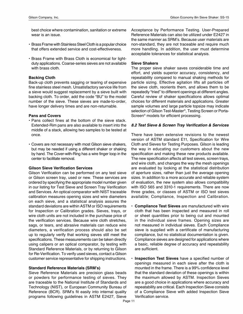
Gilson Sieve Verification Services Gilson Verification can be performed on any test sieve or Gilson screen tray, used or new. These services are ordered by specifying the appropriate model number given in our listing for Test Sieve and Screen Tray Verification and Services. An optical comparator with NIST traceable calibration measures opening sizes and wire diameters on each sieve, and a statistical analysis assures the standard deviations are within ASTM or ISO requirements for Inspection or Calibration grades. Sieves, trays, or wire cloth units are not included in the purchase price of the verification services. Because wire cloth stretches, sags, or tears, and abrasive materials can reduce wire diameters, a verification process should also be set up to regularly verify that working sieves still meet the specifications. These measurements can be taken directly using calipers or an optical comparator, by testing with Standard Reference Materials, or by returning to Gilson for Re-Verification. To verify used sieves, contact a Gilson customer service representative for shipping instructions.
Standard Reference Materials (SRM’s) Sieve Reference Materials are precision glass beads or powders for performance testing of sieves. They are traceable to the National Institute of Standards and Technology (NIST), or European Community Bureau of Reference (BCR). SRM’s fit easily into internal quality programs following guidelines in ASTM E2427, Sieve
Acceptance by Performance Testing. User-Prepared Reference Materials can also be utilized under E2427 in the same manner as SRM’s. Because user materials are non-standard, they are not traceable and require much more handling. In addition, the user must determine acceptable tolerances for statistical analysis.
Sieve Shakers The proper sieve shaker saves considerable time and effort, and yields superior accuracy, consistency, and repeatability compared to manual shaking methods for particle sizing. Effective agitation lifts all particles off the sieve cloth, reorients them, and allows them to be repeatedly “tried” to different openings at different angles. Careful review of shaker specifications allows optimal choices for different materials and applications. Greater sample volumes and large particle topsize may indicate selection of Gilson Test-Master®, Testing Screen or Porta-Screen® models for efficient processing.
8.2 Test Sieve & Screen Tray Verification & Services
There have been extensive revisions to the newest version of ASTM standard E11, Specification for Wire Cloth and Sieves for Testing Purposes. Gilson is leading the way in educating our customers about the new specification and making these new products available. The new specification affects all test sieves, screen trays, and wire cloth, and changes the way the mesh openings are evaluated by looking at the statistical distribution of aperture sizes, rather than just the average opening sizes. In addition to a more accurate and reliable system of evaluation, the new system also allows compatibility with ISO 565 and 3310-1 requirements. There are now three grades, or classes of ASTM or ISO test sieves available; Compliance, Inspection and Calibration.
• Compliance Test Sieves are manufactured with wire cloth that has been inspected and measured in roll or sheet quantities prior to being cut and mounted in the individual sieve frames. Opening sizes are not measured in individual sieves. Each Compliance sieve is supplied with a certificate of manufacturing compliance, but no statistical documentation is given. Compliance sieves are designed for applications where a basic, reliable degree of accuracy and repeatability are sufficient.
• Inspection Test Sieves have a specified number of openings measured in each sieve after the cloth is mounted in the frame. There is a 99% confidence level that the standard deviation of these openings is within the maximum allowed by ASTM. Inspection Sieves are a good choice in applications where accuracy and repeatability are critical. Each Inspection Sieve consists of a Compliance Sieve with added Inspection Sieve Verification service.
Gilson Company, Inc. Gilson Economy 8in Sieve Shaker: SS-15
Page 12
• Calibration Test Sieves have about twice as many openings measured as Inspection Sieves. The higher number of openings measured on each sieve increases the confidence level to 99.73% that the standard deviation of these openings is within the maximum allowed by ASTM. Calibration Sieves should be used in applications where a very high degree of accuracy is required. Each Calibration Sieve consists of a compliance sieve with added Calibration Sieve Verification service.
New Gilson Test Sieves are guaranteed to meet the requirements of ASTM or ISO for Compliance, Inspection or Calibration grades as ordered, but for continued assurance of performance, procedures should be in place to regularly check working sieves as they age. Wire cloth stretches, sags, or even tears, and abrasive materials reduce wire diameter, causing an increase in opening size and loss of accuracy over time.
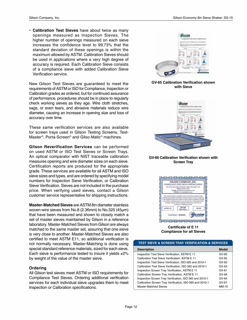
These same verification services are also available for screen trays used in Gilson Testing Screens, Test-Master®, Porta-Screen® and Gilso-Matic® machines.
Gilson Reverification Services can be performed on used ASTM or ISO Test Sieves or Screen Trays. An optical comparator with NIST traceable calibration measures opening and wire diameter sizes on each sieve. Certification reports are produced for the appropriate grade. These services are available for all ASTM and ISO sieve sizes and types, and are ordered by specifying model numbers for Inspection Sieve Verification, or Calibration Sieve Verification. Sieves are not included in the purchase price. When verifying used sieves, contact a Gilson customer service representative for shipping instructions.
Master-Matched Sieves are ASTM 8in diameter stainless woven-wire sieves from No.8 (2.36mm) to No.325 (45μm) that have been measured and shown to closely match a set of master sieves maintained by Gilson in a reference laboratory. Master-Matched Sieves from Gilson are always matched to the same master set, assuring that one sieve is very close to another. Master-Matched Sieves are also certified to meet ASTM E11, so additional verification is not normally necessary. Master-Matching is done using special standard reference materials, sized for each sieve. Each sieve is performance tested to insure it yields ±2% by weight of the value of the master sieve.
Ordering All Gilson test sieves meet ASTM or ISO requirements for Compliance Test Sieves. Ordering additional verification services for each individual sieve upgrades them to meet Inspection or Calibration specifications.
Certificate of E 11Compliance for all Sieves
GV-65 Calibration Verification shown with Sieve
GV-66 Calibration Verification shown with Screen Tray
Description Model
Inspection Test Sieve Verification, ASTM E 11 GV-60Calibration Test Sieve Verification, ASTM E 11 GV-65Inspection Test Sieve Verification, ISO 565 and 3310-1 GV-62Calibration Test Sieve Verification, ISO 565 and 3310-1 GV-63Inspection Screen Tray Verification, ASTM E 11 GV-61Calibration Screen Tray Verification, ASTM E 11 GV-66Inspection Screen Tray Verification, ISO 565 and 3310-1 GV-64Calibration Screen Tray Verification, ISO 565 and 3310-1 GV-67Master-Matched Sieves MM-70
TEST SIEVE & SCREEN TRAY VERIFICATION & SERVICES

Gilson Company, Inc. Gilson Economy 8in Sieve Shaker: SS-15
Page 13
8.3 8in Diameter ASTM Test Sieves
8IN DIAMETER ASTM TEST SIEVES
8in Stainless Steel Test Sieves
SS-8R Gilson Tapping Sieve Shaker shown with Sieves
COARSE
SERIES
FINE
SERIES
Stainless Cloth Stainless Cloth Brass Cloth ASTM E11 Stainless Frame Brass Frame Brass Frame
Alt. Std. Full Ht. Half Ht. Full Ht. Half Ht. Full Ht. Half Ht.
4in 100.0mm V8SF 4" — V8CF 4" V8CH 4" — —3-1/2in 90.0mm V8SF 3-1/2" — V8CF 3-1/2" V8CH 3-1/2" — —3in 75.0mm V8SF 3" — V8CF 3" V8CH 3" — —2-1/2in 63.0mm V8SF 2-1/2" — V8CF 2-1/2" V8CH 2-1/2" — —2.12in 53.0mm V8SF 2.12" — V8CF 2.12" V8CH 2.12" — —2in 50.0mm V8SF 2" — V8CF 2" V8CH 2" — —1-3/4in 45.0mm V8SF 1-3/4" — V8CF 1-3/4" V8CH 1-3/4" — —1-1/2in 37.5mm V8SF 1-1/2" — V8CF 1-1/2" V8CH 1-1/2" — —1-1/4in 31.5mm V8SF 1-1/4" — V8CF 1-1/4" V8CH 1-1/4" — —1.06in 26.5mm V8SF 1.06" — V8CF 1.06" V8CH 1.06" — —1in 25.0mm V8SF 1" V8SH 1" V8CF 1" V8CH 1" — —7/8in 22.4mm V8SF 7/8" V8SH 7/8" V8CF 7/8" V8CH 7/8" — —3/4in 19.0mm V8SF 3/4" V8SH 3/4" V8CF 3/4" V8CH 3/4" — —5/8in 16.0mm V8SF 5/8" V8SH 5/8" V8CF 5/8" V8CH 5/8" — —0.530in 13.2mm V8SF .530" V8SH .530" V8CF .530" V8CH .530" — —1/2in 12.5mm V8SF 1/2" V8SH 1/2" V8CF 1/2" V8CH 1/2" — —7/16in 11.2mm V8SF 7/16" V8SH 7/16" V8CF 7/16" V8CH 7/16" — —3/8in 9.5mm V8SF 3/8" V8SH 3/8" V8CF 3/8" V8CH 3/8" — —5/16in 8.0mm V8SF 5/16" V8SH 5/16" V8CF 5/16" V8CH 5/16" — —0.265in 6.7mm V8SF .265" V8SH .265" V8CF .265" V8CH .265" — —1/4in 6.3mm V8SF 1/4" V8SH 1/4" V8CF 1/4" V8CH 1/4" — —No.3-1/2 5.6mm V8SF #3-1/2 V8SH #3-1/2 V8CF #3-1/2 V8CH #3-1/2 — —No.4 4.75mm V8SF #4 V8SH #4 V8CF #4 V8CH #4 — —
No.5 4.0mm V8SF #5 V8SH #5 V8CF #5 V8CH #5 — —No.6 3.35mm V8SF #6 V8SH #6 V8CF #6 V8CH #6 — —1/8in¹ 3.18mm V8SF 1/8" V8SH 1/8" V8CF 1/8" V8CH 1/8" — —No.7 2.8mm V8SF #7 V8SH #7 V8CF #7 V8CH #7 — —No.8 2.36mm V8SF #8 V8SH #8 V8CF #8 V8CH #8 V8BF #8 V8BH #8No.10 2.0mm V8SF #10 V8SH #10 V8CF #10 V8CH #10 V8BF #10 V8BH #10No.12 1.7mm V8SF #12 V8SH #12 V8CF #12 V8CH #12 V8BF #12 V8BH #12No.14 1.4mm V8SF #14 V8SH #14 V8CF #14 V8CH #14 V8BF #14 V8BH #14No.16 1.18mm V8SF #16 V8SH #16 V8CF #16 V8CH #16 V8BF #16 V8BH #16No.18 1.0mm V8SF #18 V8SH #18 V8CF #18 V8CH #18 V8BF #18 V8BH #18No.20 850μm V8SF #20 V8SH #20 V8CF #20 V8CH #20 V8BF #20 V8BH #20No.25 710μm V8SF #25 V8SH #25 V8CF #25 V8CH #25 V8BF #25 V8BH #25No.30 600μm V8SF #30 V8SH #30 V8CF #30 V8CH #30 V8BF #30 V8BH #30No.35 500μm V8SF #35 V8SH #35 V8CF #35 V8CH #35 V8BF #35 V8BH #35No.40 425μm V8SF #40 V8SH #40 V8CF #40 V8CH #40 V8BF #40 V8BH #40No.45 355μm V8SF #45 V8SH #45 V8CF #45 V8CH #45 V8BF #45 V8BH #45No.50 300μm V8SF #50 V8SH #50 V8CF #50 V8CH #50 V8BF #50 V8BH #50No.60 250μm V8SF #60 V8SH #60 V8CF #60 V8CH #60 V8BF #60 V8BH #60No.70 212μm V8SF #70 V8SH #70 V8CF #70 V8CH #70 V8BF #70 V8BH #70No.80 180μm V8SF #80 V8SH #80 V8CF #80 V8CH #80 V8BF #80 V8BH #80No.100 150μm V8SF #100 V8SH #100 V8CF #100 V8CH #100 V8BF #100 V8BH #100No.120 125μm V8SF #120 V8SH #120 V8CF #120 V8CH #120 V8BF #120 V8BH #120No.140 106μm V8SF #140 V8SH #140 V8CF #140 V8CH #140 V8BF #140 V8BH #140No.170 90μm V8SF #170 V8SH #170 V8CF #170 V8CH #170 V8BF #170 V8BH #170No.200 75μm V8SF #200 V8SH #200 V8CF #200 V8CH #200 V8BF #200 V8BH #200No.230 63μm V8SF #230 V8SH #230 V8CF #230 V8CH #230 V8BF #230 V8BH #230No.270 53μm V8SF #270 V8SH #270 V8CF #270 V8CH #270 V8BF #270 V8BH #270No.325 45μm V8SF #325 V8SH #325 V8CF #325 V8CH #325 V8BF #325 V8BH #325No.400 38μm V8SF #400 V8SH #400 V8CF #400 V8CH #400 — —No.450 32μm V8SF #450 V8SH #450 V8CF #450 V8CH #450 — —No.500 25μm V8SF #500 V8SH #500 V8CF #500 V8CH #500 — —No.635 20μm V8SF #635 V8SH #635 V8CF #635 V8CH #635 — —
Regular Pan V8SFXPN V8SHXPN V8BFXPN V8BHXPN V8BFXPN V8BHXPNExtended Rim Pan V8SFXPE V8SHXPE V8BFXPE V8BHXPE V8BFXPE V8BHXPERegular Cover V8SFXCV V8BFXCV V8BFXCVCover with Ring V8SFXCR V8BFXCR V8BFXCR¹ Not a standard ASTM E11 size.
Combination Sieve