clarity controls gilson 30x - laserchrom · gilson pump and set its parameters. note: see the...
TRANSCRIPT

Clarity Controls Gilson 30X
Code/Rev.: M088/24B – 10. November 2006
Phone: +420 - 251 013 400 © DataApex Ltd. 2006 Fax: +420 - 251 013 401 Podohradská 1 [email protected] 155 00 Prague 5 www.dataapex.com The Czech Republic
Clarity Controls Gilson 30X
LC ENG

Clarity®, DataApex® and ® are trademarks of DataApex Ltd. Microsoft® and WindowsTM are trademarks of Microsoft Corporation DataApex reserves the right to make changes to manuals without giving prior notice. Updated manuals can be downloaded from www.dataapex.com.
Clarity - Gilson 30X Table of Contents
3
1 Gilson 30X control module.............................................4 2 Requirements ................................................................4 3 Installation procedure....................................................5
3.1 HW setup - communication ..................................5 3.2 GSIOC installation................................................5 3.3 Clarity configuration.............................................6
4 Using the control module ...............................................8 4.1 LC Pump Control..................................................8
4.1.1 Options.....................................................11 4.2 LC Monitor .........................................................11 4.3 Gilson 30X Setup ...............................................12 4.4 Notes..................................................................14 4.5 IGLN1 kit ...........................................................14 4.6 IGLN2 Adaptor ...................................................15
Clarity - Gilson 30X Table of Contents
4
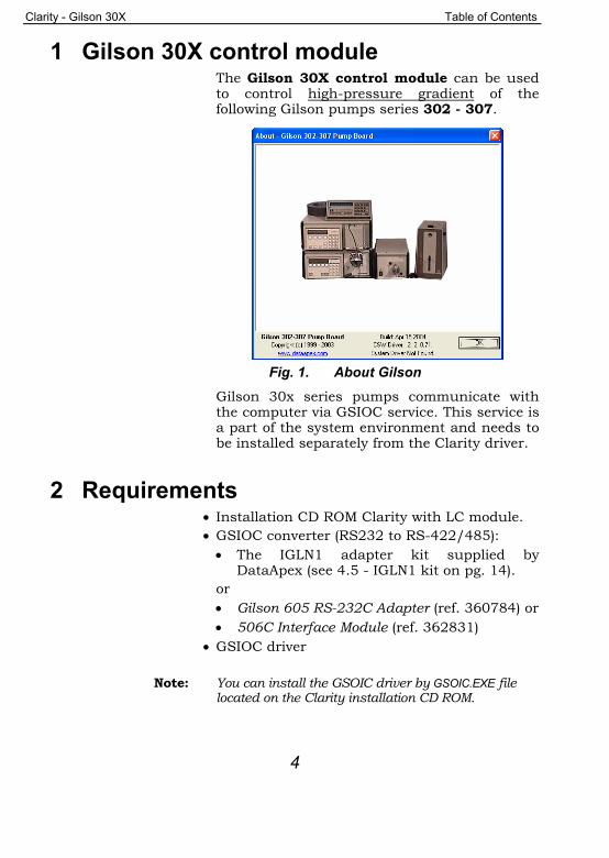
1 Gilson 30X control module The Gilson 30X control module can be used to control high-pressure gradient of the following Gilson pumps series 302 - 307.
Fig. 1. About Gilson
Gilson 30x series pumps communicate with the computer via GSIOC service. This service is a part of the system environment and needs to be installed separately from the Clarity driver.
2 Requirements • Installation CD ROM Clarity with LC module. • GSIOC converter (RS232 to RS-422/485): • The IGLN1 adapter kit supplied by
DataApex (see 4.5 - IGLN1 kit on pg. 14). or • Gilson 605 RS-232C Adapter (ref. 360784) or • 506C Interface Module (ref. 362831)
• GSIOC driver
Note: You can install the GSOIC driver by GSOIC.EXE file located on the Clarity installation CD ROM.

Clarity - Gilson 30X Table of Contents
5
3 Installation procedure 3.1 HW setup - communication
The pump is controlled by GSIOC (Gilson Serial Input Output Communication) service. This service enables to connect several devices to the same communication line. The devices are distinguished by a unique device ID - valid values from 0 to 63, can be set on the pumps by Dip switches or from the menu. Refer to the respective pump manual.
Communication cable: To convert the RS232 signals to the GSIOC (RS-422/485) standard you can use:
• The Gilson 605 RS-232C Adapter (ref. 360784) or
• 506C Interface Module (ref. 362831) or • The DataApex IGLN1 converter (see 4.5 -
IGLN1 kit on pg. 14). For the connection of additional devices special Y shaped cable is used. This cable has one Sub D 9 pin plug Canon 9M) and two Sub D 9 pin receptacle (Canon 9F) connectors. See chapter 4.6 - IGLN2 Adaptor on pg. 15.
The communication parameters are: Baud Rate 19200 is usually used to communicate with the GSIOC.
3.2 GSIOC installation Run the GSIOC.EXE from the Clarity installation CD. This will start the installation procedure. Follow the instructions in the installation. The GSIOC server and utility files will be installed to the directory Gilson created on your harddisk. In the UTILS subdirectory you can find:

Clarity - Gilson 30X Table of Contents
6
• GSCONFIG.EXE file, which can be used to change the communication settings
• GSUTIL32.EXE, which can be used for identification and immediate command sending to connected GSIOC devices.
3.3 Clarity configuration • In the System Configuration dialog press the
Add button (see the figure on pg. 7) to invoke the Available Control Modules dialog.
Fig. 2. Available Control Modules
• Select the Gilson 30X Pump Driver and press the Add button.
• The Gilson 30X Setup dialog will appear.
Fig. 3. LC Setup
Use the Scan button to detect the attached Gilson pump and set its parameters.
Note: See the chapter 4.3 - Gilson 30X Setup on pg. 12 for detailed description of the parameters.

Clarity - Gilson 30X Table of Contents
7
Caution! The pump head size must be set manually.
• After filling in the parameters press the OK
button to close the Gilson 30X Setup dialog. • The Gilson 30X Pump Driver will appear in the
Setup Control Modules list of the System Configuration dialog.
• Then drag the pump icon from the Setup Control Modules list on the left side of the System Configuration dialog to the desired Instrument tab on the right side (or use the --> button ).
• The Instrument Type must be set to LC .
Fig. 4. System Configuration
Note: The pumps are controlled independently on the GSIOC service, thus it is possible to assign the configured pumps to separate instruments (for example to create two binary gradients)

Clarity - Gilson 30X Table of Contents
8
4 Using the control module New LC Control tab appears in the Method Setup dialog, enabling the setting of the LC control method.
4.1 LC Pump Control The Method Setup – LC Control dialog serves for setting up the LC instrument method.
Fig. 5. Method Setup – LC Control
Graph The graph depicts the percentage of components as a function of time together with the overall flowrate. Data are taken over from the Gradient Table. Changes effected in this table are immediately reflected in the graph. Assignment of colours to individual components is shown in the header. The assignment is fixed and individual components are displayed in the graph from bottom to top. The flowrate is displayed in black. The graph has two vertical axes: the axis on the left refers to the mixing ratio, that on the right to the overall flowrate.

Clarity - Gilson 30X Table of Contents
9
Gradient Table A table for setting the composition of the mobile phase and the overall flowrate as a function of time. Operation is analogous to that of spreadsheets (Excel, Quatro Pro, ...). Upon clicking a cell by the left mouse button that cell is highlighted by dots and ready to receive values. A cell that fails to highlight is not available for editing.
Time [min.] The entered value represents the time at which the ratio of flowrates and the overall flowrate correspond to the values entered in the corresponding row. (These values vary continuously from one time to the next in a manner ensuring that the conditions specified in the next row are satisfied).
XXX1 (..4) [%] Represents the percentage of a component. The designation XXX1-4 is in fact replaced by the name of the component (items Solvent 1 - 4 in the Gradient Options Dialog box). Should you enter a component value such that the sum of all values exceeds 100 %, the percentage in the last column is automatically adjusted; if the percentage of the last compound is already zero, the value of the currently entered component is adjusted instead. The flowrate of a compound is calculated by multiplying the overall flowrate (indicated in the Flow column) by the corresponding percentage divided by 100.
Flow [ml/min] Indicates the overall flowrate through the column. The entered value applies to the time specified in the corresponding row.
Caution! If the flowrate set for the given pump in the Gradient Table (calculated from percentage and total flow) will exceed the maximum flowrate for the set pump head, the change will not be accepted and may invoke a communication error.

Clarity - Gilson 30X Table of Contents
10
Parameters Standby Flow Indicates the overall flowrate through the column in the STANDBY state reached after the last row of the table has been performed and the Time to Standby has passed. The time period during which the flowrate is so maintained is defined by item Standby Time. (The ratio of individual components in the respective STANDBY and IDLE states is given by the first row of the Table (the Initial row).
Time to Standby [min] Indicates the time during which the flowrate varies continuously between the last values entered in the table and the value defined by Standby Flow. This time is included in the analysis time (the CONTROL state).
Standby Time [min] The time during which the flowrate is maintained at Standby Flow. This time is included in the analysis time ( CONTROL state).
Idle State An item specifying the overall flowrate through the column outside the instrument method. The following states are possible:
Pump Off The flowrates of all components are zero.
Initial The flowrate is defined by the first row of the gradient table (the Initial row).
Standby The flowrate is the same as in the STANDBY mode and, accordingly, corresponds to the value entered in Standby Flow.
The IDLE state enters into effect each time an instrument is opened, at the end or after abortion of an analysis by the Abort command, and is maintained also when the Clarity program is shut down.

Clarity - Gilson 30X Table of Contents
11
The mixing ratio of individual components in both the IDLE and STANDBY states is given by the first row of the Gradient Table (the Initial row).
4.1.1 Options By invoking the Options button in the Method Setup – LC Control dialog, the Gradient Options dialog will appear.
Fig. 6. Gradient Options
In this dialog, the Flow Rate and Pressure units can be selected, the pressure limits set and Solvents can be enabled and named.
4.2 LC Monitor The pump status window can be invoked using the Monitor - LC Chromatograph command from the Instrument window or using the LC/GC Monitor icon from the Instrument window. This window gives actual condition readings from the pumps. The pump can be stopped from this dialog by using the Control - Stop command or by the
icon. This will stop the pump only, the analysis run is continuing and must be stopped or aborted from the Data Acquisition or Single Analysis dialogs. The flow will be resumed by using the Apply or OK butons in the Method Setup dialog.

Clarity - Gilson 30X Table of Contents
12
Fig. 7. LC Monitor
The individual solvent flow can be displayed either in flow units or as a percentage of total flow by checking the View - Component flow in % command.
4.3 Gilson 30X Setup The Gilson 30X Device Setup dialog sets the properties of the individual (also of disconnected) pumps. Invoke the dialog from the System Configuration dialog by selecting Gilson 30X item and clicking the Setup button.
Note: You can also simply double-click the "Gilson 30X Pump Driver" in the "Setup Control Modules" list on the left.
Fig. 8. LC Setup
Device Info All Gilson pumps are connected to a single COM port controlled by GSIOC service outside Clarity, consequently all the information about COM is displayed as informative only.

Clarity - Gilson 30X Table of Contents
13
Set Confirms the modifications made in the current pump setting. Changes in the setting won’t be applied until the Set or OK buttons are pressed.
Del Deletes current pump and its settings from the configuration.
Scan Detects all attached Gilson pumps. Reads their assigned numbers and stores the settings into the configuration file.
Select pump Contains list of the ID s of the detected pumps or pumps added manually by the user. User can add unattached pump to the list by writing its ID number to the Select pump field and confirming by the Set or OK buttons. The respective ID numbers are set on the individuall pumps.
Type Setting of the pump type. Newer models detect the type automatically (using the Set button), older models have to be entered manually.
Manometric module Displays the detected type of manometric module.
Head Setting of the attached head.
Caution! Must be set manually according to the head actually mounted on the pump.
Use in Flow / Microflow mode Setting of the operating mode of the pump. Microflow enables 10x lower flow with 10x higher precision than in the Flow mode. It isn’t possible to change the mode during the run, because switching the mode requires stopping the pump or step change of the flow.

Clarity - Gilson 30X Table of Contents
14
4.4 Notes Pressure displayed in the LC Monitor dialog is read from the first pump with pressure transducer assigned to an instrument. Pressure limits (Min. Pressure and Max. Pressure parameters) can be set in the Gradient Options dialog (accessible by pressing the Options button in the Method Setup - LC Control dialog).
Caution! Should these pressure limits be set outside the limits for selected pump head type, they will not be accepted by the pump and may ivoke communication error.
4.5 IGLN1 kit DataApex supplies the IGLN1 kit (o/n IGLN1) as an optional acessory.
Fig. 9. IGLN1 Converter RS232/GSIOC for Gilson
The IGLN1 kit contains all the parts needed to control the binary gradient:
• The converter box with three connectors: A SUB-D 25 pin (CANNON) receptacle (female) connector (RS232 side) and two SUB-D 9 pin receptacle connectors (for connecting two pumps or other GSIOC devices).
• Standard RS232 communication cable: (SUB-D 9 pin plug to SUB-D 25 pin plug, straight)
• Standard RS232 communication cables:

Clarity - Gilson 30X Table of Contents
15
(SUB-D 9 pin plug to SUB-D 9 pin receptacle, straight, two pieces).
4.6 IGLN2 Adaptor Additional pumps or other devices can be connected to the converter by using the IGLN2 adaptor cable (each additional device will require an additional adaptor cable).
Fig. 10. IGLN2 Adaptor GSIOC for GILSON
To order the Adaptor GSIOC for Gilson from DataApex ask for the o/n IGLN2.