operating manual - messkonzept.de · appendix d menu tree .....53 . operating manual 5 messkonzept...
TRANSCRIPT

FTC300
Fast Thermal Conductivity Analyzer
Operating Manual
Version 1.02 © Messkonzept GmbH Date of issue: 04th July 2014

Operating Manual 2
Messkonzept GmbH · Niedwiesenstr. 33 · 60431 Frankfurt · Germany
Thank you for using the FTC300 from Messkonzept. It has been designed
and manufactured using highest quality standards to give you trouble free and accurate measurements.
© Copyright Messkonzept GmbH 2014 This document is protected by copyright. Neither the whole nor any part of
it or the information contained in may be adapted or reproduced in any form except with the prior written approval of Messkonzept.
The product described in this manual and products for use with it are
subject to continuous developments and improvement. All information of technical nature and particulars of the product and its use (including the information in this manual) are given by Messkonzept in good faith. However, it is acknowledged that there may be errors or omissions in this manual. For the latest revisions to this manual contact Messkonzept or visit www.Messkonzept.de Messkonzept welcome comments and suggestions relating to the product and this manual.
Note! The design of this instrument is subject to continuous development and improvement. Consequently, this instrument may incorporate minor changes in detail from information contained in this manual.
Important! In correspondence concerning this instrument, please specify the type number and serial number as given on the type label on the right side of the instrument.
All correspondence should be addressed to: Messkonzept GmbH Niedwiesenstr. 33 60431 Frankfurt Germany Tel: +49(0)69 53056444 Fax: +49(0) 69 53056445 email: [email protected] http: www.messkonzept.de
This manual applies to: FTC300 Date of Release: May 2014 Software Version: 1.030

Operating Manual 3
Messkonzept GmbH · Niedwiesenstr. 33 · 60431 Frankfurt · Germany
1. Operator safety .................................................................................................5
1.1 Notes on Safety Conventions and Icons ........................................................... 5 1.2 Warning Notices...........................................................................................6 1.3 Safety Instructions ........................................................................................7
2. Determining Concentrations via Thermal Conductivity............................................ 8 2.1 Principle of Measurement ..............................................................................8 2.2 Principle of Operation ...................................................................................9 2.3 Measuring Gases and Ranges ......................................................................10
3. Assembly of the Instrument ..............................................................................11 3.1 FTC300 Detector Unit.................................................................................11 3.2 Installation of the FTC 300..........................................................................12 3.3 Gas Ports...................................................................................................12 3.4 Electrical Connectors and Earth....................................................................13
3.4.1 Requirements for electrical connectors.......................................................... 15 3.4.2 Ground......................................................................................................15 3.4.3 RS-232 Interface........................................................................................16 3.5 Particular Features of the FTC300................................................................... 17 4. The Front Panel .............................................................................................18
4.2 System Alarm Indicator (red) ....................................................................... 19 4.3 System Maintenance Indicator (yellow) ......................................................... 19 4.4 Operation Indicator (green) .......................................................................... 19 4.5 RIGHT / Selection Key................................................................................. 19 4.6 UP / Selection Key...................................................................................... 19 4.7 ENTER / Termination Key............................................................................19
5. Switching on the device ...................................................................................20 5.1 Warm up Screen ........................................................................................ 20 5.2 Operation Screen........................................................................................21 5.3 Top Level Main Menu ................................................................................. 21
6. Calibration......................................................................................................22 6.1 Set Offset Gas Concentration........................................................................ 22 6.2 Set Gain Gas Concentration .........................................................................23 8.3 Offset Calibration........................................................................................24 6.4 Gain Calibration .........................................................................................24
7. Diagnosis .......................................................................................................25 7.1 Parameter Menu......................................................................................... 25 7.2 Errors........................................................................................................26
8. Setup.............................................................................................................27 8.1 Unit Setup .................................................................................................28 8.1.2 Measuring Gas Setup ...............................................................................29 8.1.3 Response Time Setup ..............................................................................30 8.1.4 Multi Gas Mode List (useful with Option MGM only) .................................... 31 8.2 Relays.......................................................................................................32 8.2.1 Relay 1 Mode .........................................................................................32 8.2.2 Relay 1 Threshold ................................................................................... 33 8.2.3 Relay 1 Hysteresis ...................................................................................33 8.2.4 Relay 1 Failsafe / Not failsafe.................................................................... 34 8.2.5 Relay 1 active/frozen during Calibration ..................................................... 34
Operating Manual 4
Messkonzept GmbH · Niedwiesenstr. 33 · 60431 Frankfurt · Germany
8.2.6 Relay 2 Mode .........................................................................................35 8.2.7 Common Relay........................................................................................36
8.3.1 Current Loop ........................................................................................37 8.3.2 Analog Output 1 ...................................................................................39 8.3.4 Adjust Loop..........................................................................................40
10.4 Expert Setup ...............................................................................................41 10.4.1 Parameter.............................................................................................41 10.4.2 Access Modes .......................................................................................42 8.4.3 Reset Functions.......................................................................................43 8.4 .4 Test of Relays, Analog Outputs and Connections ........................................ 44
Note!............................................................................................................45 Appendix A System Errors .................................................................................... 46
Appendix B Specifications .................................................................................48 B.1 Performance ..............................................................................................48 B.3 Environmental conditions ............................................................................ 50 B.4 Dimensions................................................................................................50
Appendix C EG-Konformitätserklärung ................................................................... 50 Appendix D Menu Tree ........................................................................................53

Operating Manual 5
Messkonzept GmbH · Niedwiesenstr. 33 · 60431 Frankfurt · Germany
1. Operator safety This section provides information and warnings which must be followed to
ensure safe operation and retain the instrument in safe condition. Read this section carefully before beginning to install and use the instrument.
1.1 Notes on Safety Conventions and Icons
Warning!
“Warning” draws attention to application errors or actions that can lead to safety risks including the injury to persons or malfunctions – possibly even destruction of the device.
Note! “Note” indicates an additional function or hint.

Operating Manual 6
Messkonzept GmbH · Niedwiesenstr. 33 · 60431 Frankfurt · Germany
1.2 Warning Notices
The manufacturer does not assume liability for inappropriate handling of
the device. Malfunctions caused by inappropriate handling may lead to hazards.
This device is not suited for the operation in areas exposed to explosion
hazards!
Never lead explosive gases or gas mixtures into the device!
Dependent on the model the device flammable gases may be led in the
device. Check item “Glass ball filling” in the device protocol. Flammable gases may be led in devices filled with glass balls. Here, the inside space of the housing is densely filled with glass balls (Ø 0.6mm). In the unlikely case that a leakage caused an explosive atmosphere, the small spaces between the glass balls prevent a coincidental ignition caused by a further malfunction of the device from propagating.
Never open the housing of the FTC300, especially because of the loose
glass balls. When the device had been opened it may not work safely with flammable gases.
Disconnect the device from the power supply to prevent an unintended
start of the device, if a safe operation of the device is not guaranteed.
For operation of the device in the field a rain protection is recommended.
Operating Manual 7
Messkonzept GmbH · Niedwiesenstr. 33 · 60431 Frankfurt · Germany
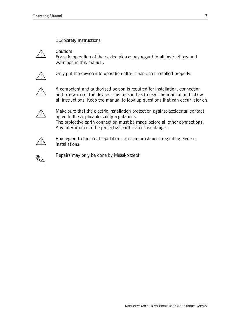
1.3 Safety Instructions
Caution!
For safe operation of the device please pay regard to all instructions and warnings in this manual.
Only put the device into operation after it has been installed properly.
A competent and authorised person is required for installation, connection
and operation of the device. This person has to read the manual and follow all instructions. Keep the manual to look up questions that can occur later on.
Make sure that the electric installation protection against accidental contact
agree to the applicable safety regulations. The protective earth connection must be made before all other connections. Any interruption in the protective earth can cause danger.
Pay regard to the local regulations and circumstances regarding electric
installations.
Repairs may only be done by Messkonzept.
Operating Manual 8
Messkonzept GmbH · Niedwiesenstr. 33 · 60431 Frankfurt · Germany
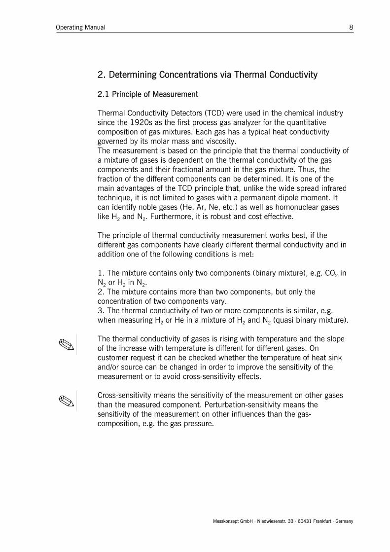
2. Determining Concentrations via Thermal Conductivity 2.1 Principle of Measurement Thermal Conductivity Detectors (TCD) were used in the chemical industry
since the 1920s as the first process gas analyzer for the quantitative composition of gas mixtures. Each gas has a typical heat conductivity governed by its molar mass and viscosity. The measurement is based on the principle that the thermal conductivity of a mixture of gases is dependent on the thermal conductivity of the gas components and their fractional amount in the gas mixture. Thus, the fraction of the different components can be determined. It is one of the main advantages of the TCD principle that, unlike the wide spread infrared technique, it is not limited to gases with a permanent dipole moment. It can identify noble gases (He, Ar, Ne, etc.) as well as homonuclear gases like H2 and N2. Furthermore, it is robust and cost effective.
The principle of thermal conductivity measurement works best, if the
different gas components have clearly different thermal conductivity and in addition one of the following conditions is met:
1. The mixture contains only two components (binary mixture), e.g. CO2 in
N2 or H2 in N2. 2. The mixture contains more than two components, but only the
concentration of two components vary. 3. The thermal conductivity of two or more components is similar, e.g.
when measuring H2 or He in a mixture of H2 and N2 (quasi binary mixture).
The thermal conductivity of gases is rising with temperature and the slope of the increase with temperature is different for different gases. On customer request it can be checked whether the temperature of heat sink and/or source can be changed in order to improve the sensitivity of the measurement or to avoid cross-sensitivity effects.
Cross-sensitivity means the sensitivity of the measurement on other gases than the measured component. Perturbation-sensitivity means the sensitivity of the measurement on other influences than the gas-composition, e.g. the gas pressure.

Operating Manual 9
Messkonzept GmbH · Niedwiesenstr. 33 · 60431 Frankfurt · Germany
2.2 Principle of Operation The FTC300 sensor determines the quantitative composition of gas
mixtures by measuring the thermal conductivity between a heat source and a heat sink through the gas mixture. The measuring gas is conducted to the sensor through a stainless steel block that is kept at a constant temperature of 60°C. This temperature a stabilized using a control loop such that the block can be used as heat sink. A thin membrane of micro-mechanical silicon chip serves as heat source. Two thin film resistors are integrated into the membrane, one is used for both the membrane the other for measuring its temperature. A second control loop stabilizes the membrane temperature at 135°C. Above and below the membrane two small cavities are etched into the silicon, which are filled by diffusion with the measuring gas. The surfaces opposite to the membrane are thermally connected with the heat sink. Dependent on the thermal conductivity of the gas more or less energy is led off the membrane. The voltage needed to keep the temperature of the membrane constant is a measure for the thermal conductivity of the gas. Both resistors on the membrane are protected by an inert coating in order to prevent chemical reactions with the measuring gas.
Figure 3.0 Thermal Conductivity Detector (principle)
Heat sink; Tconst = 60°C
H e a t s ource;T c o n s t = 135°C Trans f e r r e d h e a t
Gas flow

Operating Manual 10
Messkonzept GmbH · Niedwiesenstr. 33 · 60431 Frankfurt · Germany
2.3 Measuring Gases and Ranges Depending on the gas pair the measurement is possible within certain mixing
ratios.
Measur-ing Gas
Carrier Gas Basic range Smallest range
Smallest suppressed zero
range
Multi Gas Mode
H2 N2 or air 0% - 100% 0% - 0.5% 98% - 100% Yes H2 Ar 0% - 100% 0% - 0.4% 99% - 100% Yes H2 He 20% - 100% 20% - 40% 85% - 100% On request H2 CH4 0% - 100% 0% - 0.5% 98% - 100% On request H2 CO2 0% - 100% 0% - 0.5% 98% - 100% On request He N2 or air 0% - 100% 0% - 0.8% 97% - 100% Yes He Ar 0% - 100% 0% - 0.5% 98% - 100% Yes CO2 N2 or air 0% - 100% 0% - 3% 96% - 100% Yes CO2 Ar 0% - 60% 0% - 10% - Yes Ar N2 or air 0% - 100% 0% - 3% 96% - 100% Yes Ar CO2 40% - 100% - 80% - 100% Yes
CH4 N2 or air 0% - 100% 0% - 2% 96% - 100% Yes CH4 Ar 0% - 100% 0% - 1.5% 97% - 100% Yes O2 N2 0% - 100% 0% - 15% 85% - 100% Yes O2 Ar 0% - 100% 0% - 2% 97% - 100% Yes N2 Ar 0% - 100% 0% - 3% 97% - 100% Yes N2 CO2 0% - 100% 0% - 4% 96% - 100% On request
NH3 H2 0% - 100% 0% - 5% 95% - 100% On request NH3 N2 0% - 100% 0% - 10% 60% - 100% On request CO H2 0% - 100% 0% - 2% 99% - 100% On request
SF6 N2 or air 0% - 100% 0% - 2% 96% - 100% On request Other gases and ranges on request
The FTC300 must not be used with explosive gases. Flammable gases as H2
and CH4 may only be used in devices filled with glass balls. A gas mixture of a flammable gas with an inert gas in a mixing ratio such, that it is still inflammable for any amount of air added is called totally inertised. Totally inertised gases can also be used in devices without glass balls.
“Basic range” is the largest possible measuring range and is set by default. The linearization is performed over the basic range. The smallest measuring ranges at the beginning and the end of the basic range can be deduced from calibration. The smallest possible range between the basic range and the smallest ranges at the end beginning and the end of the range can be estimated by linear Interpolation.
Measuring ranges are set in the “Current Loop” Menu, see Chapter Analog Out.
The Multi Gas Mode (MGM) is a configuration that allows for the consecutive measurement of different gas pairs. The gas pair can be switched at via the control panel or via the RS232-interface. Gas pairs labeled “Yes” in the table above are commonly used. Gas mixtures labelled “On request” can also be implemented with little effort.

Operating Manual 11
Messkonzept GmbH · Niedwiesenstr. 33 · 60431 Frankfurt · Germany
3. Assembly of the Instrument 3.1 FTC300 Detector Unit The FTC300 detector unit consists of a hermetically sealed pressure
proofed stainless steel block with a gas duct, which is suited for pressures up to 20 bar. Sample gas entering through the gas inlet is guided to the micromechanical thermal conductivity sensor and further downstream to the outlet port. In particular the pneumatics is designed to minimize the influence of a changing gas flow. The operating temperature of 60°C is stabilized by a highly accurate PI control loop. In order to avoid electrical interference on the measuring output the high performance analog adaption circuit is directly mounted on top of the stainless steel block. The piggyback-mounted processor board digitizes the signal in a 24bit A/D converter. The μ-controller performs all calculations, as linearization, calibrations and cross sensitivity compensation directly on the detector unit.
Figure 3.0 FTC300 Detector Unit

Operating Manual 12
Messkonzept GmbH · Niedwiesenstr. 33 · 60431 Frankfurt · Germany
3.2 Installation of the FTC 300 132 mm
4,5mm
Mounting holes
Figure 3.1 Mounting holes shown from the reverse side of the housing The FTC300 is designed for wall fastening. The four mounting holes are
shown in the picture above. M4 cylinder head bolts are suitable.
3.3 Gas Ports On the bottom of the FTC300 housing two tubes with 6mm outer diameter
for gas connection are located. They are labeled with “GAS IN” and “GAS OUT”. For low requirements regarding gas tightness and resistance to pressure the tubes can be used as hose connector. For permanent gas and pressure tightness compression fittings are recommended (e.g. by “Swagelok”©).
A leakage test after connecting the gas ports is recommended.

Operating Manual 13
Messkonzept GmbH · Niedwiesenstr. 33 · 60431 Frankfurt · Germany
3.4 Electrical Connectors and Earth
A B C
Top View
1: Analog Input 1
2: Analog Output 2
3: Analog Reference
4: Digital Input (24V)
5: Ground6: Analog Output 1
7: Analog Input 2 1: Relay 1 - A
2: Power Supply-GND3: Relay 1 - B4: Power Supply +24V5: Relay 2 - A
6: Relay 2 - B
7: Relay 3 - A
8: Relay 3 - B
1: 0 (4) - 20mA, isolated +
2: 0 (4) - 20mA, isolated -
3: Ground
4: TxD
5: RxD
Figure 3.2 Electrical Connectors, view from top on the device The electric contacts are joined in three plug connectors, see Figure above.
For details on the function of each contact, see Table below. The cables (712, IP67) with an extruded connector plug and a length of two meters (five meters available on request) are part of the purchased parts package. The cables have open ends the cross-section of the conductors in cable A and C is 0,14mm2, for cable B 0,25mm2.
The protection class of the device is only effective with all cables attached. In
case cable A is not used, connector plug A has to be closed with an end fitting.

Operating Manual 14
Messkonzept GmbH · Niedwiesenstr. 33 · 60431 Frankfurt · Germany
Connector A (7-pins) Pin
No. Conductor colouring
Function Description
1 white Analog Input 1 0 to 10V, 24 bit resolution 2 brown Analog Output 2 0 to 10V, 16 bit resolution 3 green GND GND for pins 1, 2, 6, 7 4 yellow Digital Input (DIN) low:<4.6V; high;11.4V 5 grey GND GND for pin 4 6 pink Analog Output 1 0 to 10V, 16 bit resolution 7 blue Analog Input 2 0 to 10V, 24 bit resolution
Connector B (5-pins) Pin
No. Conductor colouring
Function Description
1 white Current Loop send 2 brown Current Loop
return
0 (4) to 20mA, floating, isolated ±500V to ground, max. 800 Ohm burden, 16 bit resolution
3 black Serial Interface RS232
GND for pin4, 5
4 blue Serial Interface RS232
TxD (transmit)
5 grey Serial Interface RS232
RxD (receive)
Connector C (8-pins) Pin
No. Conductor colouring
Function Description
1 white Relay 1 isolated contact; 36V, max.1A 2 brown Power Supply - GND 3 green Relay 1 isolated contact; 36V, max.1A 4 yellow Power Supply + + 24V (18V to 36V), max. 700mA 5 grey Relay 2 isolated contact; 36V, max.1A 6 pink Relay 2 isolated contact; 36V, max.1A 7 blue Common Relay 3 isolated contact; 36V, max.1A 8 red Common Relay 3 isolated contact; 36V, max.1A

Operating Manual 15
Messkonzept GmbH · Niedwiesenstr. 33 · 60431 Frankfurt · Germany
3.4.1 Requirements for electrical connectors
Before using the device make sure that the power supply is in accordance
with the specifications of the device and that all electric connections correspond to the information given in this manual.
The FTC300 is a device with protection class III. Relay contacts and inputs
should only be operated with safety extra low voltage (SELV;4kV). The power supply has to comply with the PELV specification (protective extra low voltage) according to EN 60204-1.
Unlike SELV, PELV may be grounded at the output side.
3.4.2 Ground
Figure 3.3 Connection to ground To comply with EN 60204-1, the device has to be installed such that the
power supply (PELV) is connected to ground with only its ground conductor, see Figure above.
The shielding of cable A, B and C has to be connected to the functional ground. Dependent on the circumstances gas inlet and gas outlet can be grounded in addition.
Connections to ground should be made with low-resistant, large diameter, short cables to one neutral point.
Operating Manual 16
Messkonzept GmbH · Niedwiesenstr. 33 · 60431 Frankfurt · Germany
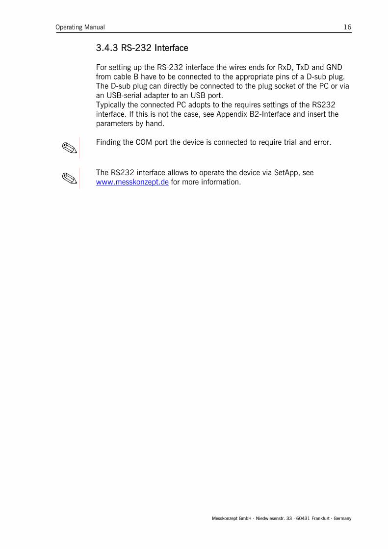
3.4.3 RS-232 Interface For setting up the RS-232 interface the wires ends for RxD, TxD and GND
from cable B have to be connected to the appropriate pins of a D-sub plug. The D-sub plug can directly be connected to the plug socket of the PC or via an USB-serial adapter to an USB port.
Typically the connected PC adopts to the requires settings of the RS232 interface. If this is not the case, see Appendix B2-Interface and insert the parameters by hand.
Finding the COM port the device is connected to require trial and error.
The RS232 interface allows to operate the device via SetApp, see www.messkonzept.de for more information.

Operating Manual 17
Messkonzept GmbH · Niedwiesenstr. 33 · 60431 Frankfurt · Germany
3.5 Particular Features of the FTC300 * Accurate and long term stable thermal conductivity measurement
* High sensitivity (e.g. measuring range 0 Vol.% to 0.5Vol.% H2 in N2)
* Fast response with a T90 time of less than 1 sec (dependent on flow rate)
* Low noise (<10ppm H2 in N2)
* Precise linearization for binary gas mixtures of H2, He, CO2, CH4 in N2 or Ar and N2 in Ar are preset
* Additional customized linearization with polynomial up to sixth order available
* Isolated 0/4-20mA output, start and end point can be set to any concentration
* Conventional 2-point calibration or simple one-gas calibration
* Display indication in ppm or Vol.%
* Pressure proof and vacuum leak tight stainless steel 1.4571) gas duct
* Three isolated relays for indication of alarms and instrument status
* Small and robust transmitter in powder-coated aluminum housing for field use (IP65)
* Access to all values and parameters via RS 232 interface
* Digital output with 1ppm resolution over the whole 100Vol.% range
*
PC-based service program SetApp offers easy to operate calibration routines, diagram of measured concentration vs. time and possibility to write data to a log file.
* Compensation for cross sensitivity and interfering components
* Multi Gas Mode allows sequential measurement of up to 16 binary gas mixtures
* Dimensions: Width 145mm, Height 80mm plus connectors, Depth 85mm
* Power supply 18V to 36V DC / 700mA
Operating Manual 18
Messkonzept GmbH · Niedwiesenstr. 33 · 60431 Frankfurt · Germany
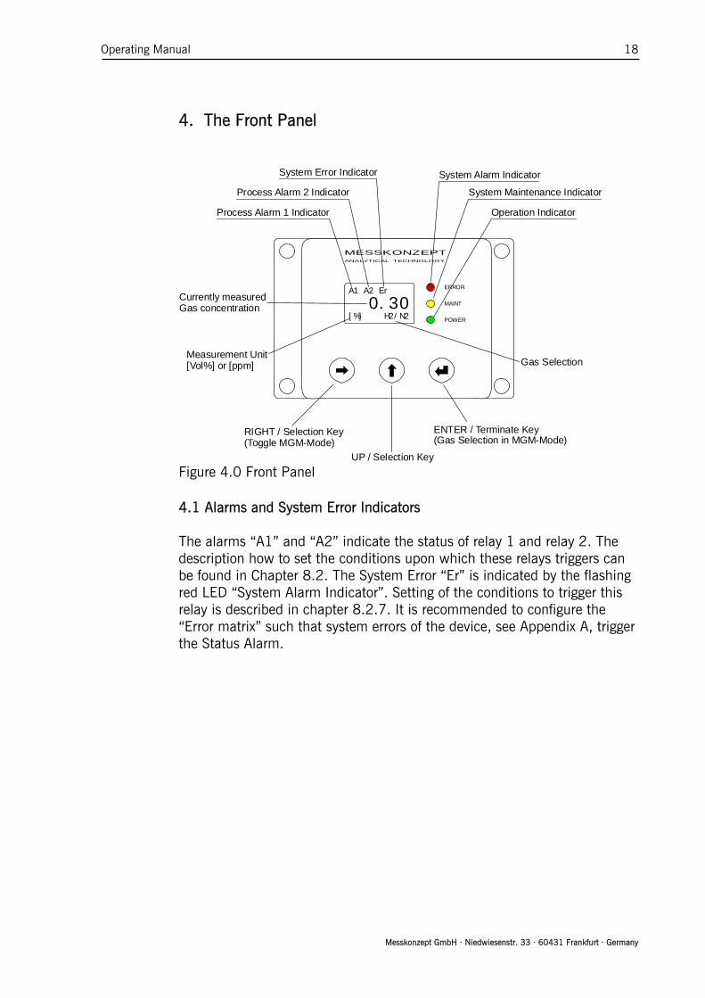
4.1 Alarms and System Error Indicators The alarms “A1” and “A2” indicate the status of relay 1 and relay 2. The
description how to set the conditions upon which these relays triggers can be found in Chapter 8.2. The System Error “Er” is indicated by the flashing red LED “System Alarm Indicator”. Setting of the conditions to trigger this relay is described in chapter 8.2.7. It is recommended to configure the “Error matrix” such that system errors of the device, see Appendix A, trigger the Status Alarm.
4. The Front Panel
A1 A2 Er
0.30[%] H2/N2
ERROR
POWER
MESSKONZEPTANALYTICAL TECHNOLOGY
MAINT
RIGHT / Selection Key(Toggle MGM-Mode)
ENTER / Terminate Key(Gas Selection in MGM-Mode)
UP / Selection Key
System Alarm Indicator
System Maintenance Indicator
Operation IndicatorProcess Alarm 1 Indicator
Process Alarm 2 Indicator
System Error Indicator
Measurement Unit[Vol%] or [ppm] Gas Selection
Currently measuredGas concentration
Figure 4.0 Front Panel

Operating Manual 19
Messkonzept GmbH · Niedwiesenstr. 33 · 60431 Frankfurt · Germany
4.5 RIGHT / Selection Key
The <RIGHT> key enables the operator to scroll through the various menu items of menus and submenus. The currently selected menu item is marked by black background and is called with the <ENTER> key. In submenus requiring numerical inputs, the <RIGHT> key scrolls to the next digit and to “ESC / OK” at the end.
4.6 UP / Selection Key
In menus or submenus the <UP> key quits the recent menu and changes to the superior menu and ultimately to the main menu. To quit menus with an “ESC”/”OK” option, select one of these fields with the <RIGHT> key and confirm with <ENTER>. In submenus requiring numerical inputs, the <UP> key changes the selected digit.
4.7 ENTER / Termination Key
The <ENTER> calls the item, that is marked as selected by the black background. Menu items are selected by the <RIGHT> key. In submenus with an “ESC”/”OK” option the <ENTER> key confirms the selection of “ESC” or “OK”.
4.2 System Alarm Indicator (red)
The flashing red LED indicates a system. Dependent on the configuration of
the “Alarm matrix”, see chapter 8.2.7 Common Relay, also other errors can be shown.
4.3 System Maintenance Indicator (yellow)
The flashing yellow LED indicates that the instrument demands
maintenance. It still works but the specifications given in Appendix B1 “Performance” may not me met anymore.
4.4 Operation Indicator (green) The flashing green LED indicates that power is supplied and the internal
processor works properly.

Operating Manual 20
Messkonzept GmbH · Niedwiesenstr. 33 · 60431 Frankfurt · Germany
Optional: Devices with Multi Gas Mode (MGM) The <ENTER> gives fast access from the measured value display to changing the gas mixture. This mode is indicated by highlighting the currently selected gas pair. Pressing <ENTER> selects the next entry of the MGM list. Pressing <RIGHT> again deactivates fast access mode of the mixture selection. See chapter “Multi Gas Mode List” for a description how to modify the MGM list.
5. Switching on the device This chapter describes switching on the device. The warm up screen, see
Figure 5.0, shows the block temperature while the block warms up. After the warm up, the device switches to the operation screen, see Figure 5.1, from here the operation screen the main menu is opened. The device can be run in two different modes, the safety mode and the normal mode. In the safety mode every action has to be confirmed by the operator code (default: 111.000). In both modes some actions require an expert code, for example changing the operator code and changing between normal and safety mode. This manual refers to the device operated in normal mode.
5.1 Warm up Screen Warm Up
58.3Set: 60.0 °C
Figure 5.0 Warm up Screen
The warm up screen shows the current block temperature during warm up
in the center of the screen, see Figure above. The target value of the block temperature, here 60°C, are shown in the bottom line of the screen. The current loop, relays and analog outputs are deactivated during warm up. When the difference between the measured temperature and the target value is smaller than 0.3 °C, the device switches to the operation screen.
Pressing the <UP> key during warm up switches directly to operation screen and activates the current loop. The displayed concentration value is not precise until the block is warmed up.

Operating Manual 21
Messkonzept GmbH · Niedwiesenstr. 33 · 60431 Frankfurt · Germany
5.2 Operation Screen A1 A2 Er
0.30[%] H2/N2
Figure 5.1 Operation Screen
After the warm up of the block the operation screen is shown, see Figure
above. The first line provides the status information. Alarms are indicated by “A1” and “A2”, system errors are indicated by “Er”, see chapter “Relays” and Appendix A. The third line shows the unit of the measurement, ppm or Vol.% and the currently selected gas pair, in the example above hydrogen in nitrogen. The display resolution in ppm is 1ppm, the number of digits displayed in Vol.% indication is set according to the customers wish and can be changed in the Expert menu in the parameter menu. Press the <UP> key to get access to the top level main menu.
5.3 Top Level Main Menu Operation
CalibrationDiagnosisSetup
Figure 5.2 Top Level Main Menu
The main menu is the origin of the menu tree that gives access to the
submenus, see Appendix E. Selecting “Operation” as shown above and pressing <ENTER> or <UP> returns to the Operation screen. To access the submenus, select the desired submenu and press <ENTER>. The menu paths given in the following chapters start at the main menu.

Operating Manual 22
Messkonzept GmbH · Niedwiesenstr. 33 · 60431 Frankfurt · Germany
6. Calibration
For devices operated in “safety mode”, the operator code is required to access the calibration menu. By default the operator code is set to 111.000.
The goal of the calibration is that the measured concentration is in agreement with the given test gas concentration. To obtain this, two calibration parameters that correspond to the gain and the offset of a linear equation are available.
A two-point calibration requires two test gases. Both calibration parameters, offset and gain, are adjusted. The concentration of the test gases does not have to meet the beginning and the end of the measuring range, a difference of ±10% is permitted.
The menu sequence is designed such that prior to a gain always an offset calibration has to be done first. Usually a single point calibration determining a new offset value is sufficient to obtain a good calibration. In this case a test gas of any concentration in the measuring range is feasible. For two point calibrations it is preferable to use the lower concentration for the offset calibration and the higher concentration for the gain calibration.
Use of substitute gases Instead of using toxic or explosive gases for calibration the use of substitute gases is possible. A substitute gas has at a certain concentration the same thermal conductivity as the test gas it is substituting, such it can also be used for the calibration instead. Please contact Messkonzept for details.
6.1 Set Offset Gas Concentration A1 A2 Er
0.30[%] H2/N2
OperationCalibrationDiagnosisSetup
H2 in N2CalibrateOffset GasGain Gas
Offset Gasset: 0.00000new: 0.00000[%] ESC/OK
Figure 6.0 Offset Gas Menu Before performing a calibration, the concentration of the used test gases
have to be set. In the submenu “Offset Gas” the used concentration of the offset gas has to

Operating Manual 23
Messkonzept GmbH · Niedwiesenstr. 33 · 60431 Frankfurt · Germany
be entered. Select the submenu “Offset Gas” by pressing the <RIGHT> key and press <ENTER> to open the menu for the numerical entry. Enter the value by changing each digit to the desired number. The position of the curser in the number is moved by the <RIGHT> key, the value of the digit at the current position of the curser is changed with the <UP> key. When the correct value is set move the cursor to “OK” and confirm with <ENTER>.
6.2 Set Gain Gas Concentration
OperationCalibrationDiagnosisSetup
H2 in N2CalibrateOffset GasGain Gas
Gain Gasset: 100.000new: 100.000[%] ESC/OK
Figure 6.1 Gain Gas Menu Prior to a two point calibration the gain gas concentration has to be set in
the submenu “Gain Gas”. This menu is operated analogously “Offset Gas” menu described above.
Operating Manual 24
Messkonzept GmbH · Niedwiesenstr. 33 · 60431 Frankfurt · Germany
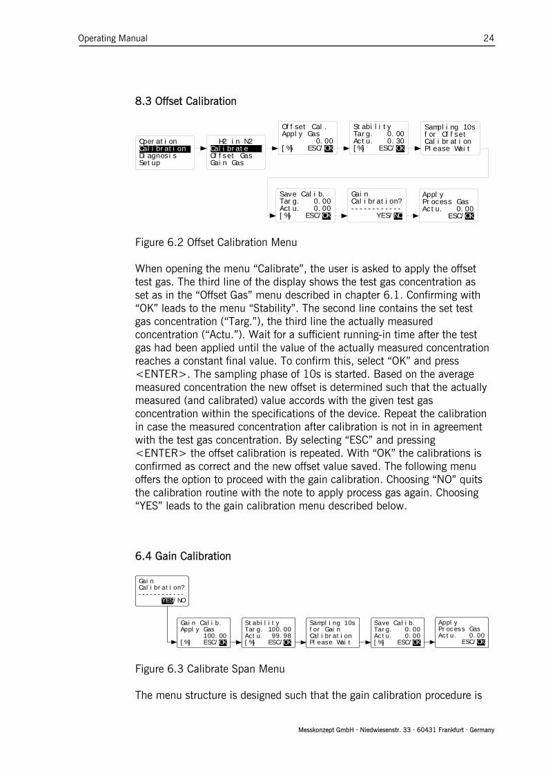
8.3 Offset Calibration
Figure 6.2 Offset Calibration Menu When opening the menu “Calibrate”, the user is asked to apply the offset
test gas. The third line of the display shows the test gas concentration as set as in the “Offset Gas” menu described in chapter 6.1. Confirming with “OK” leads to the menu “Stability”. The second line contains the set test gas concentration (“Targ.”), the third line the actually measured concentration (“Actu.”). Wait for a sufficient running-in time after the test gas had been applied until the value of the actually measured concentration reaches a constant final value. To confirm this, select “OK” and press <ENTER>. The sampling phase of 10s is started. Based on the average measured concentration the new offset is determined such that the actually measured (and calibrated) value accords with the given test gas concentration within the specifications of the device. Repeat the calibration in case the measured concentration after calibration is not in in agreement with the test gas concentration. By selecting “ESC” and pressing <ENTER> the offset calibration is repeated. With “OK” the calibrations is confirmed as correct and the new offset value saved. The following menu offers the option to proceed with the gain calibration. Choosing “NO” quits the calibration routine with the note to apply process gas again. Choosing “YES” leads to the gain calibration menu described below.
6.4 Gain Calibration
Gain Calib.Apply Gas
100.00[%] ESC/OK
StabilityTarg. 100.00Actu. 99.98[%] ESC/OK
Sampling 10sfor GainCalibrationPlease Wait
Save Calib.Targ. 0.00Actu. 0.00[%] ESC/OK
GainCalibration?------------
YES/NO
ApplyProcess GasActu. 0.00
ESC/OK
Figure 6.3 Calibrate Span Menu The menu structure is designed such that the gain calibration procedure is
Offset Cal.Apply Gas
0.00[%] ESC/OK
Stabilit y Targ. 0 . 0 0 Actu. 0 . 3 0 [%] ES C / O K
S a m p l i ng 10sf o r O f fsetC a l i b r ationP l e a s e Wait
Save Calib.Targ. 0.00Actu. 0.00[%] ESC/OK
GainCalibrati o n ? --------- - - -
YES / N O
A p p l y P r o c e s s GasA c t u . 0.00
ESC/OK
O p e r atio n C a l i brat i o n D i a g nosi s S e t u p
H 2 in N2C a l ibrateO f f set GasG a i n Gas

Operating Manual 25
Messkonzept GmbH · Niedwiesenstr. 33 · 60431 Frankfurt · Germany
only accessible after an offset calibration. The steps of the gain calibration correspond to the offset calibration described above. The gain calibration can be canceled in any submenu by selecting “ESC”, not changing the gain.
7. Diagnosis
For devices operated in “safety mode”, the operator code is needed to access the diagnosis menu. By default the operator code is set to 111.000.
The menu provides two useful functions for the diagnosis of the device. 7.1 Parameter Menu
OperationCalibrationDiagnosisSetup
0.30[%] H2/N2
ParameterErrors
Compound Rawset: 3000.00------------P001 OK
Figure 7.0 Parameter Menu
The configuration of the device is defined by about 170 parameters. The
“Parameter” menu gives read-only access to these parameters. This may help an experienced user to diagnose malfunction caused by wrong settings. The parameter menu gives enables to scroll through the entire parameter list. Contact Messkonzept for detailed information on the parameter. The first line contains the name of the parameter, the last line its number. To move forward in the list, press <ENTER>, to move backwards, press <Up>. To leave the parameter menu mark <OK> by pressing <RIGHT> and confirm with <ENTER>.
Some parameters can be changed in the expert setup, see chapter 8.4.1.

Operating Manual 26
Messkonzept GmbH · Niedwiesenstr. 33 · 60431 Frankfurt · Germany
7.2 Errors
No Errors------------Reset All?
NO/YES
OperationCalibrationDiagnosisSetup
ParameterErrors
0.30[%] H2/N2
Figure 7.1 Error Menu
When the device is in the measuring mode or calibrating several
parameters are continuously checked for plausibility. The parameters checked, the list of possible errors and the ranges defining a plausible value can be found in Appendix A. Errors are indicated by a flashing red line on the front panel and “Er” written in the first line of the display. In the default setting in this case also the status relay signalizes the error externally. The menu “Errors” gives access to the list of current errors. “No Errors” indicates that no error is pending, for pending errors the name of the error according to Appendix A is written. Pressing <ENTER> proceeds to the next pending error and <UP> to the previous error. To leave the parameter menu press <RIGHT> and <ENTER>. A reset of the errors is not necessary as errors that are no longer pending are immediately removed from the error list.

Operating Manual 27
Messkonzept GmbH · Niedwiesenstr. 33 · 60431 Frankfurt · Germany
8. Setup
For devices operated in “safety mode”, the operator code is required to access the setup menu. By default the operator code is set to 111.000.
OperationCalibrationDiagnosisSetup Instr. Set.
Relay Set.Output Set.Expert Set.
A1 A2 Er
0.30[%] H2/N2
Figure 8.0 Setup Menu
The “Setup” menu contains four submenus.
• The “Instrument Setup” selects the measured gas pair, the units and the T90 response time of the exponential filter.
• The “Relay Setup” defines the conditions to trigger the relays. • In the “Output Setup” the properties of the external signal channels
are set. • The “Expert Setup” gives write access to the parameters, reset
functions, access modes and codes and test signals for subsequent connected equipment.

Operating Manual 28
Messkonzept GmbH · Niedwiesenstr. 33 · 60431 Frankfurt · Germany
8.1 Unit Setup
OperationCalibrationDiagnosisSetup Instr. Set.
Relay Set.Output Set.Expert Set.
Unit -> Vol%H2 in N2
T90 ResponseList for MGM
A1 A2 Er
0.30[%] H2/N2
Unit -> ppmH2 in N2
T90 ResponseList for MGM
Figure 8.1 Unit Setup Menu
The first point of the submenu allows to select the unit. Pressing
<ENTER> the alternates the displayed unit between ppm and Vol.%. Quit the menu with the <UP>key. The value of P76 (see Chapter 8.4.1 Parameter) fixes the number of digits after the point between 1 and 4 when displaying Vol.%. The resolution in ppm is always 1ppm.
All internal calculations are done in ppm. Access of measuring values via the RS-232 interface will always give the numbers in ppm with 1ppm resolution.

Operating Manual 29
Messkonzept GmbH · Niedwiesenstr. 33 · 60431 Frankfurt · Germany
8.1.2 Measuring Gas Setup
OperationCalibrationDiagnosisSetup Instr. Set.
Relay Set.Output Set.Expert Set.
Unit -> Vol%H2 in N2
T90 ResponseList for MGM
A1 A2 Er
0.30[%] H2/N2
Unit -> ppmO2 in N2
T90 ResponseList for MGM
Unit -> ppmUser Poly.T90 ResponseList for MGM
Figure 8.2 Measuring Gas Setup Menu
In the second line in the “Instrument Setup” indicates the currently
measured binary gas mixture. For devices with Multi-Gas-Mode (MGM) pressing <ENTER> changes to the next binary gas mixture included in the device. Up to 16 binary gas mixtures can be included.
For every binary gas mixture the corresponding set of linearization parameters and a set of calibration values is automatically used. The settings of relays, the scaling of the analog outputs and the measuring range do not change when using a different binary gas mixture.

Operating Manual 30
Messkonzept GmbH · Niedwiesenstr. 33 · 60431 Frankfurt · Germany
8.1.3 Response Time Setup
T90 Responseset: 1.00000new: 1.00000[s] ESC/OK
OperationCalibrationDiagnosisSetup Instr. Set.
Relay Set.Output Set.Expert Set.
Unit -> Vol%H2 in N2
T90 ResponseList for MGM
A1 A2 Er
0.30[%] H2/N2
Figure 8.3 Response Time Menu
In the menu “T90 Response” the response time of the exponential filter is
adjusted. This filter reduces the influence of fast variations of the raw signal. The numerical entry gives value in seconds. The range between 0s and 100s is permitted for this value, reasonable values lie between 0.5s to 10s.
Setting “T90 Response” to 0.0 turns off the exponential filter. The true response time is influenced by the gas exchange time which depends on the pneumatic installation and flow rate of measuring gas. A gas flow of 80l/h leads to a gas exchange time of under 0.5s measured from the gas inlet of the device.

Operating Manual 31
Messkonzept GmbH · Niedwiesenstr. 33 · 60431 Frankfurt · Germany
8.1.4 Multi Gas Mode List (useful with Option MGM only)
H2 in N2------------Not in list
ESC/OK
OperationCalibrationDiagnosisSetup Instr. Set.
Relay Set.Output Set.Expert Set.
Unit -> Vol%H2 in N2
T90 ResponseList for MGM
A1 A2 Er
0.30[%] H2/N2
O2 in N2------------Not in list
ESC/OK
User poly.------------Not in list
ESC/OK
H2 in N2------------Not in list
ESC/OK
H2 in N2------------Is in list
ESC/OK
Figure 8.4 Multi-Gas-Mode Menu
Devices supporting the Multi Gas Mode (MGM) can measure in succession
up to 16 different binary gas mixtures that are selected after the customers wish at purchasing order. From the list of all available binary gas mixtures, a short list for the short-key access from the operational screen can be edited, further called “List for MGM”. Binary gas mixtures can be added to or removed from the “List for MGM”; gas mixtures labelled with “Is in list” are included in the short list, “Not in List” if this is not the case. The binary gas mixture to be added or removed to or from the list is selected with the <UP>. The <RIGHT>key changes to the third display line, where the <ENTER> key switches between “Is in list” and “Not in List”. Press <RIGHT> to select “OK” to confirm the selection.
Using the Multi Gas Mode list (MGM list) For devises with MGM the MGM list can be accessed from the operation screen by pressing the <RIGHT> key. This is indicated by the active gas mixture. By pressing <ENTER> the next binary gas mixture from the “List for MGM” is selected. Pressing <RIGHT> again deactivates the gas mixture selection.

Operating Manual 32
Messkonzept GmbH · Niedwiesenstr. 33 · 60431 Frankfurt · Germany
8.2 Relays
OperationCalibrationDiagnosisSetup
Instr. Set.Relay Set.Output Set.Expert Set.
A1 A2 Er
0.30[%] H2/N2
Relay 1Relay 2------------Common Relay
Figure 8.5 Relays Menu
The menu “Relay Setup” gives access to the configuration of the two
process alarm relays “Relay 1“, “Relay2” and the status alarm relay “Common Relay”. The thresholds and hysteresis for “Relay 1” and “Relay 2” can be set. The status relay indicates a malfunction of the device, but can also indicate the threshold alarms. Each relay may be configured as failsafe or not failsafe.
The threshold relays are indicated by “A1” respectively “A2” in the first display line.
The common relay is indicated by “Er” in the first display line and by the flashing red LED on the front panel.
8.2.1 Relay 1 Mode
OperationCalibrationDiagnosisSetup
Instr. Set.Relay Set.Output Set.Expert Set.
A1 A2 Er
0.30[%] H2/N2
Relay 1Relay 2------------Common Relay
R1 Mode ***FailsafeCal. active
ESC/OK
R1 Mode L/HR1 ThresholdR1 Hyst.
ESC/OK
R1 Mode H\LR1 ThresholdR1 Hyst.
ESC/OK
R1 Mode OFF------------------------
ESC/OK
Figure 8.6 Relays R1 Mode Menu
Relay 1 can be operated in different modes described below. Selecting
“Relay 1” and pressing <ENTER> gives access to the different modes. 1) “R 1Mode L/H” signalling from low to high
When the measured concentration increases and reaches the threshold,
Operating Manual 33
Messkonzept GmbH · Niedwiesenstr. 33 · 60431 Frankfurt · Germany
the alarm is triggered. When the measured concentration decreases again below the threshold, the alarm is only reset if the value decreases below the threshold minus the hysteresis given in “R1 Hysteresis”. The hysteresis is specified in percent of threshold.
2) “R 1Mode H/L” signalling from high to low When the measured concentration decreases and reaches the threshold, the alarm is triggered. When the measured concentration increases again above the threshold, the alarm is only reset if the value increases above the threshold plus the hysteresis given in “R1 Hysteresis”. The hysteresis is specified in percent of threshold
3) “R 1Mode OFF” Relay 1 is not used.
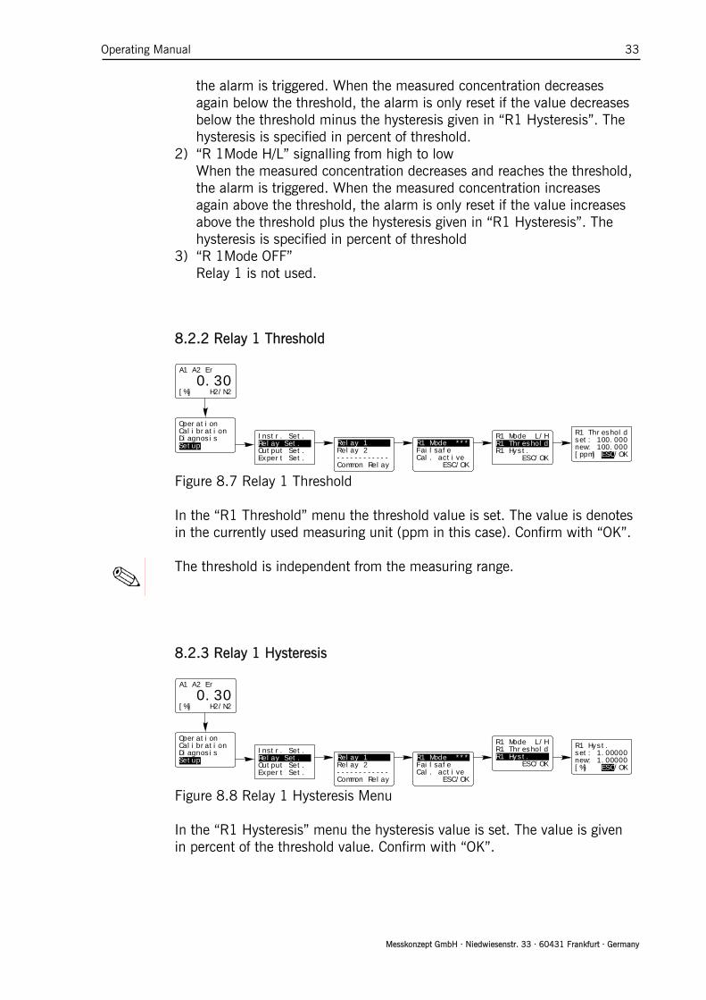
8.2.2 Relay 1 Threshold
OperationCalibrationDiagnosisSetup
Instr. Set.Relay Set.Output Set.Expert Set.
A1 A2 Er
0.30[%] H2/N2
Relay 1Relay 2------------Common Relay
R1 Mode ***FailsafeCal. active
ESC/OK
R1 Mode L/HR1 ThresholdR1 Hyst.
ESC/OK
R1 Thresholdset: 100.000new: 100.000[ppm] ESC/OK
Figure 8.7 Relay 1 Threshold
In the “R1 Threshold” menu the threshold value is set. The value is denotes
in the currently used measuring unit (ppm in this case). Confirm with “OK”.
The threshold is independent from the measuring range.
8.2.3 Relay 1 Hysteresis
OperationCalibrationDiagnosisSetup
Instr. Set.Relay Set.Output Set.Expert Set.
A1 A2 Er
0.30[%] H2/N2
Relay 1Relay 2------------Common Relay
R1 Mode ***FailsafeCal. active
ESC/OK
R1 Mode L/HR1 ThresholdR1 Hyst.
ESC/OK
R1 Hyst.set: 1.00000new: 1.00000[%] ESC/OK
Figure 8.8 Relay 1 Hysteresis Menu
In the “R1 Hysteresis” menu the hysteresis value is set. The value is given
in percent of the threshold value. Confirm with “OK”.

Operating Manual 34
Messkonzept GmbH · Niedwiesenstr. 33 · 60431 Frankfurt · Germany
8.2.4 Relay 1 Failsafe / Not failsafe
R1 Mode ***FailsafeCal. active
ESC/OK
R1 Mode ***Not failsafeCal. active
ESC/OK
OperationCalibrationDiagnosisSetup
Instr. Set.Relay Set.Output Set.Expert Set.
A1 A2 Er
0.30[%] H2/N2
Relay 1Relay 2------------Common Relay
Figure 8.9 Process Alarm Failsafe / Not failsafe
The threshold alarms can be configured as “Failsafe” or “Not Failsafe”.
“Failsafe” means that the relay is live with no error pending. Hence, the alarm is indicated if the threshold is reached or if the closed-circuit contact is interrupted. “Not Failsafe” means that the relay is open with no error pending and closes when an error appears. Press <ENTER> to switch between “Failsafe” and “Not Failsafe”. The change is made effective by pressing <RIGHT> three times to mark “OK” and confirm with <ENTER>.
8.2.5 Relay 1 active/frozen during Calibration
OperationCalibrationDiagnosisSetup
Instr. Set.Relay Set.Output Set.Expert Set.
A1 A2 Er
0.30[%] H2/N2
Relay 1Relay 2------------Common Relay
R1 Mode ***FailsafeCal. active
ESC/OK
R1 Mode ***FailsafeCal. frozen
ESC/OK Figure 8.10 Relay 1 active/frozen during calibration
The relay can be configured as “Calibration active” or “Calibration frozen”.
With “Calibration frozen” the relay does not respond to any changes of the measured concentration during the calibration procedure and stays in the state it was in when the calibration began. With “Calibration active” the

Operating Manual 35
Messkonzept GmbH · Niedwiesenstr. 33 · 60431 Frankfurt · Germany
relay acts according to its current settings during calibration. Press <ENTER> to switch between “Calibration frozen” and “Calibration active”. The change is made effective by pressing <RIGHT> two times to mark “OK” and confirm with <ENTER>.
8.2.6 Relay 2 Mode
OperationCalibrationDiagnosisSetup
Instr. Set.Relay Set.Output Set.Expert Set.
A1 A2 Er
0.30[%] H2/N2
Relay 1Relay 2------------Common Relay
R2 Mode ***FailsafeCal. active
ESC/OK
R2 Mode L/HR2 ThresholdR2 Hyst.
ESC/OK
R2 Mode H\LR2 ThresholdR2 Hyst.
ESC/OK
Aux. L/HR2 ThresholdR2 Hyst.
ESC/OK
Aux. H\LR2 ThresholdR2 Hyst.
ESC/OK
Maintenance------------------------
ESC/OK
R2 Mode OFF------------------------
ESC/OK
Figure 8.11 Relay 2 Mode Menu
“Relay 2” provides all functionalities of“Relay 1”, see description above.
In addition Relay 2 permits the external signaling of the “Maintenance” alarm or monitoring the external auxiliary signal with the menu “Aux.”.

Operating Manual 36
Messkonzept GmbH · Niedwiesenstr. 33 · 60431 Frankfurt · Germany
8.2.7 Common Relay
OperationCalibrationDiagnosisSetup
Instr. Set.Relay Set.Output Set.Expert Set.
A1 A2 Er
0.30[%] H2/N2
Relay 1Relay 2------------Common Relay Alarm matrix
FailsafeCal. active
ESC/OK
Relay 1 ON------------C. Alarm NO
ESC/OK
Relay 2 ON------------C. Alarm NO
ESC/OK
EEPROM ERROR------------C. Alarm YES
ESC/OK
Figure 8.12 Common Relays Menu
In the “Common Relay” menu based on the following errors is defined:
• threshold alarms from relay 1 und 2 • external error • internal errors (see Appendix A for a detailed description)
The menu “Alarm matrix” opens the list of errors that can be included in the common relay. Scroll forward through the list with <ENTER> and backwards with <UP>. The third display line indicates whether this error is included in the common (“C. Alarm YES”) relay or not (“C. Alarm NO”). Press <RIGHT> to proceed to the third display line press <ENTER> to switch between“C. Alarm YES” and “C. Alarm NO”. Confirm with “OK”. If one or more of errors included in the Alarm matrix by “C. Alarm YES” are pending, the common relay triggers.
In the factory settings all internal errors described in Appendix A are included in the common relay.

Operating Manual 37
Messkonzept GmbH · Niedwiesenstr. 33 · 60431 Frankfurt · Germany
8.3 Analog Output Setup
OperationCalibrationDiagnosisSetup
Instr. Set.Relay Set.Output Set.Expert Set.
A1 A2 Er
0.30[%] H2/N2
Current LoopAnalog Out 1Analog Out 2Adjust Loop
Figure 8.13 Output Setup The FTC300 is equipped with three analog outputs. “Current Loop” is an
isolated current output. “Analog Out 1” and “Analog Out 2” are not DC-isolated outputs with an output range from 0 to 10 V.
8.3.1 Current Loop
OperationCalibrationDiagnosisSetup
Instr. Set.Relay Set.Output Set.Expert Set.
A1 A2 Er
0.30[%] H2/N2
Current LoopAnalog Out 1Analog Out 2Adjust Loop
I/O ModeCal. active------------
ESC/OK
4-20mAC-> IOutMinC-> IOutMax
ESC/OK
I/O ModeCal. active------------
ESC/OK
I/O ModeCal. frozen------------
ESC/OK
4-20mA (Err)C-> IOutMinC-> IOutMax
ESC/OK
4-20mAC-> IOutMinC-> IOutMax
ESC/OK
C-> IOutMinset: 0.00000new: 0.00000[ppm] ESC/OK
C-> IOutMaxset: 1000000new: 1000000[%] ESC/OK
4-20mAC-> IOutMinC-> IOutMax
ESC/OK
0-20mAC-> IOutMinC-> IOutMax
ESC/OK
0-20mA (Err)C-> IOutMinC-> IOutMax
ESC/OK
0-20mA Corr.C-> IOutMinC-> IOutMax
ESC/OK
Const. I-OutI-Out Const.I-Out Error
ESC/OK
Figure 8.14 Current Loop Set Up

Operating Manual 38
Messkonzept GmbH · Niedwiesenstr. 33 · 60431 Frankfurt · Germany
In the “Current Loop” menu the range of the current output and the
behavior of the current loop during calibration and in case of an error are defined.
Press <RIGHT> to scroll through the list of the different modes. Select “OK” and confirm with <ENTER> to confirm the selection of the mode.
Current loop output modes:
“I/O Mode” “4-20mA” The loop current ranges from 4mA to 20mA. 4mA correspond to the starting point of the measuring range as defined in “IoutMin”, 20mA correspond to the starting point of the measuring range as defined in “IoutMax”.
“I/O Mode” “4-20mA (Err)” This mode works in the analogous manner as the previously described mode. In case of an error the current output is set to the value specified in the submenu “I-Out Error”.
“I/O Mode” “0-20mA” The loop current ranges from 0mA to 20mA. 0mA correspond to the starting point of the measuring range as defined in “IoutMin”, 20mA correspond to the starting point of the measuring range as defined in “IoutMax”.
“I/O Mode” “0-20mA (Err)” This mode works in the analogous manner as the previously described mode. In case of an error the current output is set to the value specified in the submenu “I-Out Error”.
“I/O Mode” “0-20mA (Corr.)” The current output of this mode creates a voltage drop from 0V to 10V at a 510 Ohm resistor. (Correction factor: Parameter 73)
“Const. I-Out” The output of the current loop is constant current specified in the submenu “I-Out Const”. Set the value to 0.0mA if the current loop is not used.
The current specified for signalling errors should be outside the measuring range. By default the error current is set to 3.0mA, values up to 22.0mA can be set.
When choosing the “Cal. active” option the currently measured value is
shown at the current output during the calibration. When choosing the “Cal. frozen” the last measured value before the calibration began is shown at the current output.

Operating Manual 39
Messkonzept GmbH · Niedwiesenstr. 33 · 60431 Frankfurt · Germany
8.3.2 Analog Output 1
Figure 8.15 Analog Output 1 Adjustment “Analog Out 1” is a non DC-isolated 0 to 10V output. The maximum load is
1kOhm. The following parameters can be routed to “AOut-Parameter “:
Value Param.
No. Param. Name Description
0 - - No output 1 P0 Compound ppm Measuring signal in ppm 2 P1 Compound raw Linearized raw signal in ppm 3 P2 Norm. signal Normalized measuring signal 4 P3 TC average Thermal Conductivity in mV 5 P53 Block Temp Block Temperature 6 P133 Aux ppm Linearized and calibrated signal in ppm of the
raw signal applied to analog input 1 7 P134 Aux norm. Normalized signal applied to analog input 1
8 P67 IOut Current Loop
“AOut1-Offset” and “AOut-Gain” allow to scale the analog output according
to a linear equation (Output= AOut1-Gain*signal+AOut1_Offset).
O p e r a tio n C a l i b rat i o n D i a g n osi s S e t u p
I n s tr. Set.R e l ay Set.O u t put Set.E x p ert Set.
A 1 A 2 Er 0. 3 0
[ % ] H 2 / N 2
Current LoopAnalog Out 1Analog Out 2Adjust Loop
AOut1-P a r a m AOut1-O f f s e t AOut1-G a i n
A O u t 1-Params e t : 0.00000n e w : 0.00000
ESC/OK
AOut1-P a r a m AOut1-O f f s e t AOut1-G a i n
A O u t 1-Offsets e t : 0.00000n e w : 0.00000[ V ] ESC/OK
AOut1- P a r a m AOut1- O f f s e t AOut1- G a i n
A O u t1-Gains e t : 1.00000n e w : 1.00000
ESC/OK
Operating Manual 40
Messkonzept GmbH · Niedwiesenstr. 33 · 60431 Frankfurt · Germany
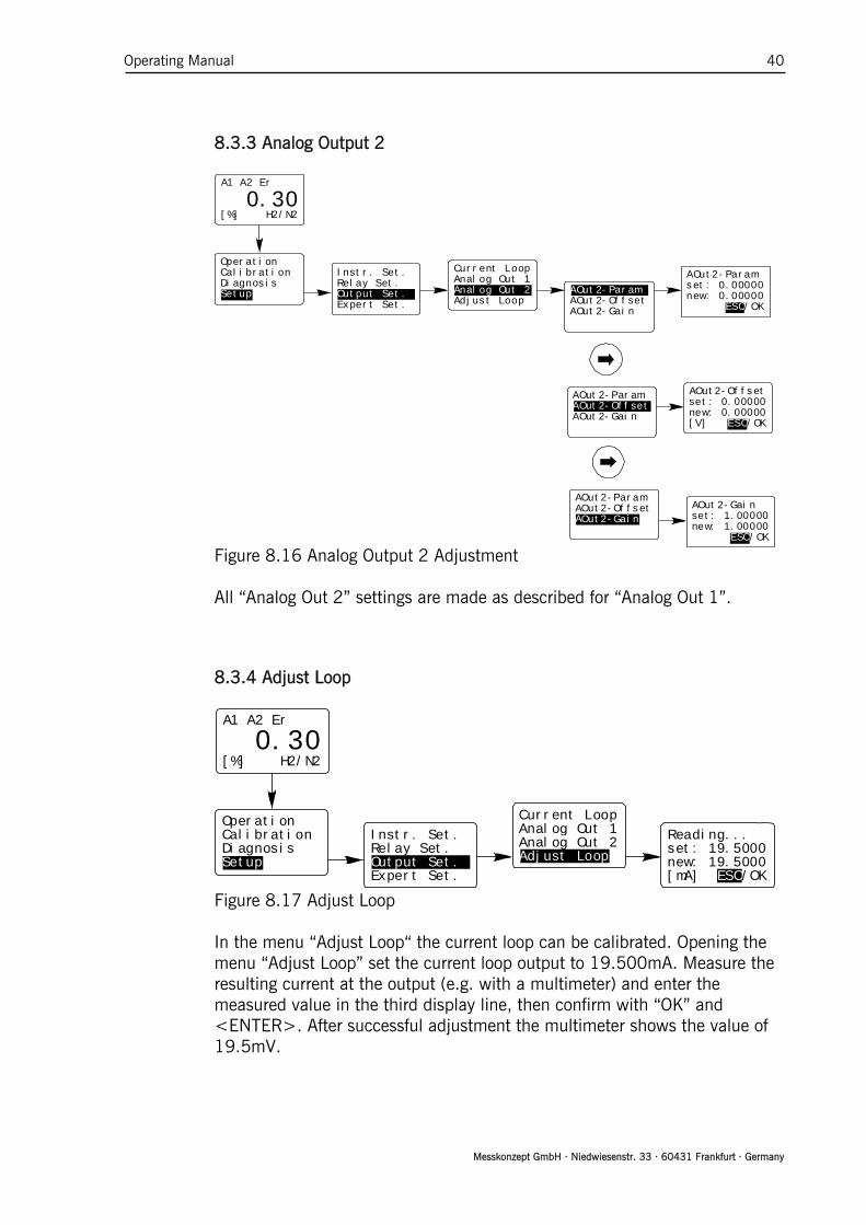
8.3.3 Analog Output 2
Figure 8.16 Analog Output 2 Adjustment All “Analog Out 2” settings are made as described for “Analog Out 1”.
8.3.4 Adjust Loop
OperationCalibrationDiagnosisSetup
Instr. Set.Relay Set.Output Set.Expert Set.
A1 A2 Er
0.30[%] H2/N2
Current LoopAnalog Out 1Analog Out 2Adjust Loop
Reading...set: 19.5000new: 19.5000[mA] ESC/OK
Figure 8.17 Adjust Loop In the menu “Adjust Loop“ the current loop can be calibrated. Opening the
menu “Adjust Loop” set the current loop output to 19.500mA. Measure the resulting current at the output (e.g. with a multimeter) and enter the measured value in the third display line, then confirm with “OK” and <ENTER>. After successful adjustment the multimeter shows the value of 19.5mV.
O p e r a tio n C a l i b rat i o n D i a g n osi s S e t u p
I n s tr. Set.R e l ay Set.O u t put Set.E x p ert Set.
A 1 A 2 Er 0. 3 0
[ % ] H 2 / N 2
Current LoopAnalog Out 1Analog Out 2Adjust Loop
AOut2-P a r a m AOut2-O f f s e t AOut2-G a i n
A O u t 2-Params e t : 0.00000n e w : 0.00000
ESC/OK
AOut2-P a r a m AOut2-O f f s e t AOut2-G a i n
A O u t 2-Offsets e t : 0.00000n e w : 0.00000[ V ] ESC/OK
AOut2- P a r a m AOut2- O f f s e t AOut2- G a i n
A O u t2-Gains e t : 1.00000n e w : 1.00000
ESC/OK

Operating Manual 41
Messkonzept GmbH · Niedwiesenstr. 33 · 60431 Frankfurt · Germany
8.4 Expert Setup
The Expert Setup provides a couple of functionalities that should only be
used by an advanced user or expert. • set parameters • reset of the FTC300 to factory settings • changing “Operator Code” and “Expert Code” • swap between “Normal Mode” and “Safety Mode” • Simulation of alarm and voltage outputs
This level is for advanced users or experts and should not be entered by
normal operators. It is in the expert’s responsibility to set the parameters properly. The default expert code is “222.000”.
OperationCalibrationDiagnosisSetup
Instr. Set.Relay Set.Output Set.Expert Set.
A1 A2 Er
0.30[%] H2/N2
Expert Codeset: 0.00000new: 0.00000
ESC/OK
Figure 8.18 Expert Level Entry
8.4.1 Parameter Parameter
Access ModesReset Funct.I/O Test
Compound ppmset: 2105.13------------P000 OK
LCD Contrastset: 25.0000Change ?P009 OK
LCD Contrastset: 25.0000new: 25.0000
ESC/OK
LCD Contrastset: 25.0000Change ?P009 OK
Figure 10.19 Expert Level Parameter Menu
The configuration of the FTC300 is represented by a set of about 170
parameters. These parameters govern all settings and functions of the device. Press <ENTER> to scroll forward through the list and backwards by pressing <UP>. Some parameters cannot be changed (e.g. “Compound ppm”, see Figure

Operating Manual 42
Messkonzept GmbH · Niedwiesenstr. 33 · 60431 Frankfurt · Germany
above) other can be changed (e.g. “LED Contrast”, see Figure above). All changeable parameters are indicated by “Change?” in the third line. Enter the new number in the numerical submenu, mark “OK” and confirm with <ENTER>.
Note! Setting the parameter to improper values cause a failure of the entire device.
8.4.2 Access Modes
Figure 8.20 Expert Level Access Modes Menus This menu allows to change codes for the “Operator Code” and the “Expert
Code”. Further, the device can be switched between “Safety Mode” and “Operation Mode”. The operation mode is used with the setting “1.00000” in the menu “Mode Set” and “3.00000” for the safe mode. Each change in this mode requires the manual input of the actual Operator Code.
P a ram e t e r A c ces s M o d e s R e set F u n c t . I / O T e s t
Operat. CodeExpert CodeMode Set
Op e r a t . C o d ese t : 1 1 1 . 0 0 0ne w : 1 1 1 . 0 0 0
E S C / O K
Operat. CodeExpert CodeMode Set
E x p e r t C o d es e t : 2 2 2 . 0 00n e w : 2 2 2 . 0 00
E S C / OK
Operat. CodeExpert CodeMode Set
Mode Set s e t : 1 . 0 0 0 00n e w : 1 . 0 0 0 00
E S C / OK

Operating Manual 43
Messkonzept GmbH · Niedwiesenstr. 33 · 60431 Frankfurt · Germany
8.4.3 Reset Functions Parameter
Access ModesReset Funct.I/O Test
Restart onlyFactory Set.Default Set.Save Calibr.
Figure 8.21 Expert Level Reset Functions Menus
This menu provides three reset functions and the possibility to save the
current calibration parameters to the Factory Settings. Restart only: Restart of the software Factory Set.: Resets all parameters to the factory set values Default Set.: Resets all parameters to the default set values.
CAREFUL: These values are not suited for a properly working device.
Save Calibration: Saves the parameters relevant to calibration. They can be retrieved by “Factory Set.”
If a rest to Factory Settings was performing without saving the calibration parameters beforehand a new calibration might be necessary.
When the device is reset to “Default Setting” the parameters relevant for
the proper operation are overwritten by default values. With these values the device will not work. The correct parameters (contact Messkonzept) have to be written to the device again, see chapter 8.4.1 or the manual of SetApp under www.messkonzept.de

Operating Manual 44
Messkonzept GmbH · Niedwiesenstr. 33 · 60431 Frankfurt · Germany
8.4 .4 Test of Relays, Analog Outputs and Connections Parameter
Access ModesReset Funct.I/O Test Relays
Current LoopAnalog Out
Rel 1 openRel 2 openRel 3 openDIN low
RelaysCurrent LoopAnalog Out
I-Out Constset: 10.0000new: 10.0000[mA] ESC/OK
RelaysCurrent LoopAnalog Out Analog Out 1
Analog Out 2
AO 1 Voltageset: 0.00000new: 0.00000[V] ESC/OK
Analog Out 1Analog Out 2
AO 2 Voltageset: 0.00000new: 0.00000[V] ESC/OK
Figure 8.22 Analog I/O Test
The “I/O Test” menu provides the opportunity to set the following properties to a defined status in order to test subsequent connected equipment:
• Relay 1 (Rel 1) (open/closed) • Relay 2 (Rel 2) (open/closed) • Common Relay (Rel 3) (open/closed) • Current of current loop • Voltage for Analog Out 1 • Voltage for Analog Out 2
The digital input “DIN” is “low” for voltages below 4.6V and “high” above 11.4 V. The output “Current Loop” can be set to currents between 0 and 22mA. The analog outputs 1 and 2 can be set to supply a voltage between 0V and 10V.

Operating Manual 45
Messkonzept GmbH · Niedwiesenstr. 33 · 60431 Frankfurt · Germany
Note! All test signals are permanently on until leaving the “I/O Test” menu. It is the responsibility of the expert to assure that the I/O test does not interfere with the subsequent connected systems and processes in an unintended way.

Operating Manual 46
Messkonzept GmbH · Niedwiesenstr. 33 · 60431 Frankfurt · Germany
Appendix A System Errors Displayed label Cause Default
range corrective measure
EEPROM ERROR
Error reading or writing data to or from internal FLASH-EEPROM
- Repeat procedure. If the error persists, send the device to Messkonzept with description of error.
CAL GAIN ER Calibration gain exceeding max. allowed range
0.5-1.5 Check if the used test gas concentration accords with the set concentration. Repeat procedure. If the error persists, send the device to Messkonzept with description of error.
CAL OFFS ER Calibration offset exceeding max. allowed range
100 mV Check if the used test gas concentration accords with the set concentration. Repeat procedure. If the error persists, send the device to Messkonzept with description of error.
CAL DEV ER Calibration deviation exceeding max. allowed range
50000 ppm
Check if the used test gas concentration accords with the set concentration. Repeat procedure. If the error persists, send the device to Messkonzept with description of error.
CAL VAR ER Calibration variation exceeding max. allowed range
1000ppm Check if the used test gas concentration accords with the set concentration. Repeat procedure. If the error persists, send the device to Messkonzept with description of error.
BT MIN ER Block temperature below specified range
SetTemp–0.3°C
The device still warms up or a sudden change of ambient temperature, gas flow disturbed the temperature control loop. Wait for a couple of minutes.

Operating Manual 47
Messkonzept GmbH · Niedwiesenstr. 33 · 60431 Frankfurt · Germany
The device is used outside the specified ambient temperature or gas temperature range. Consider the specifications. If the error persists, send the device to Messkonzept with description of error.
BT MAX ER Block temperature above specified range
SetTemp+0.3°C
The device still warms up or a sudden change of ambient temperature, gas flow disturbed the temperature control loop. Wait for a couple of minutes. The device is used outside the specified ambient temperature or gas temperature range. Consider the specifications. If the error persists, send the device to Messkonzept with description of error.
BU MIN ER Bridge voltage below specified range
1V Send the device to Messkonzept with description of error.
BU MAX ER Bridge voltage above specified range
11V Send the device to Messkonzept with description of error.
TC MIN ER WLD-signal below specified range
500mV Send the device to Messkonzept with description of error.
TC MAX ER WLD-signal above specified range
7000mV Send the device to Messkonzept with description of error.
EXT. ERROR Error routed from input “DIN” (0V=no error, +24V=error)
Signal >14V
Check the external unit surveyed by the external error.

Operating Manual 48
Messkonzept GmbH · Niedwiesenstr. 33 · 60431 Frankfurt · Germany
Appendix B Specifications B.1 Performance Linearity < 1% of range Warm up time Approx. 20min; up to 1h for
small ranges
Flow rate 10l/h-150l/h, recommended 60l/h to 80l/h
T90-time <1sec at flow rate higher 60l/h (or user selected)
Noise < 1% of smallest range Drift at zero point < 2% of smallest range per
week
Repeatability < 1% of range Error due to change
of ambient temperature
< 1% of smallest range per 10°C
Error due to change of flow at 80l/h
< 1% of smallest range per 10l/h
Gas pressure Max. 2000kPa (20 bar) Error due to change
of pressure (>800hPa)
< 1% of smallest range per 10hPa

Operating Manual 49
Messkonzept GmbH · Niedwiesenstr. 33 · 60431 Frankfurt · Germany
B.2 Electrical Display: 128 x 64 dot graphic LCD display Keypad: 3x membrane covered push-buttons Analog Input : Non isolated Voltage range: 0 to 10V Input resistance: Approx. 50 kOhm Resolution: 24 bit Current Loop: Linearized 0/4 to 20 mA User selectable Fully floating: ±500V to ground
(max.) Load: 800 Ohm (max.) Resolution: 16 bit Analog Output 1/2: Non isolated Voltage range: 0 to 10V Load: 1000 Ohm (min.) Resolution: 16 bit Relay 1/2/3: Isolated contact Maximum Voltage: 36V Maximum Power: 10W Typ. Number of Switches: 107 Power Supply: Voltage range: 18V to 36V DC Max. Current: 700mA Typical Current: 300mA
Interface: RS-232 Baud rate: 19.2 kbaud Data: 8 bit Parity: None Stop: 1 Flow control: None

Operating Manual 50
Messkonzept GmbH · Niedwiesenstr. 33 · 60431 Frankfurt · Germany
B.3 Environmental conditions Operating temp.: -20°C to 50°C (-4 to 122°F) or
-5°C to 50°C (23 to 122°F) glass balls filled version Storage temp.: -25°C to 70°C (-15 to 160°F) (not-condensing) Vibration: 10 to 150Hz (2g peak) Protection class: IP 65
B.4 Dimensions
Dimensions: Depth: 85mm Width: 145mm Height: 80mm without connectors Weight: Max. 1800g Mounting: Wall mounting
Appendix C EG-Konformitätserklärung

Operating Manual 51
Messkonzept GmbH · Niedwiesenstr. 33 · 60431 Frankfurt · Germany

Operating Manual 52
Messkonzept GmbH · Niedwiesenstr. 33 · 60431 Frankfurt · Germany
zur EG-Konformitätserklärung des Analysators FTC 300
Der Nachweis der Übereinstimmung mit den genannten Richtlinien erfolgt durch Anwendung folgender Europäischer Normen: EN 61326-1:2006: Elektrische Betriebsmittel für Leittechnik und Laboreinsatz – EMV-Anforderungen: Angewendet werden die Anforderungswerte aus folgender Tabelle: Tabelle 2: Prüfanforderungen und Ergebnissen für Geräte für den Gebrauch in industriellen Bereichen.
Anschluss Störphänomen Referenznorm Prüfwert Prüfergebnis
Gehäuse elektrostatische Entladung EN 61000-4-2 4kV/8kV,Kontakt/Luft kein Einfluss
elektromagnetische Felder EN 61000-4-3 10V/m,80-1000MHz, 80%AM max. Einfluss <1% kleinste MBU*
DC-Versorgungs-anschluss
Schnelle Transienten EN 61000-4-4 1kV kein Einfluss
Stossspannungen EN 61000-4-5 0,5kV (L-L);1kV (L-G) kein Einfluss
leitungsgeführte HF-Signale EN 61000-4-6 10V, 0,15-80MHz, 80%AM max. Einfluss <0,5% kleinste MBU*
Eingang / Ausgang Signal/Steuerung
Schnelle Transienten EN 61000-4-4 0,5kV kein Einfluss
Stossspannungen EN 61000-4-5 1kV (L-G) Leitungslänge begrenzt
leitungsgeführte HF-Signale EN 61000-4-6 10V max. Einfluss <0,7% kleinste MBU*
* Kleinste Messbereichumfang (MBU) für die Messung von H2 in N2 von 0,5Vol% ist zugrunde gelegt. Die Ermittlung der Störaussendungsgrenzwerte basiert auf folgende Norm: EN 55011:2009: Industrielle, wissenschaftliche und medizinische Geräte – Funkstörungen – Grenzwerte und Messverfahren (IEC/CISPR 11:2009, modifiziert) Tabelle 5: Grenzwerte für die elektromagnetische Störstrahlung von Geräten der Klasse B, Gruppe 1, die auf einem Messplatz gemessen werden (schließt die Störaussendungsgrenzwerte für Betriebsmittel der Klasse A, Tabelle 3, ein)
Anschluss Frequenzbereich
[MHz] Grenzwerte
Quasispitzenwert Referenznorm Prüfergebnis
Gehäuse 30-230 30dB(μV/m) EN 55022 Erfüllt**
230-1000 37dB(μV/m) EN 55022 Erfüllt** ** 20dB unter Grenzwerte Quasispitzenwert
Untersuchtes Prüfmuster: FTC 200, Stand 12-2011 Prüfort/-zeit: EMV-Prüflabor, BIS Prozesstechnik GmbH, Frankfurt-Höchst, KW 49-2011, KW04-2012 Prüfer: Dipl.-Phys. H. Hahn, Quality-Engineering Hahn (Ingenieurbüro), Frankfurt

Operating Manual 53
Messkonzept GmbH · Niedwiesenstr. 33 · 60431 Frankfurt · Germany
Appendix D Menu Tree Operation
Calibration |_Calibrate |_Offset Gas |_Gain Gas Diagnosis |_Parameter |_Errors Setup |_Instr. Setup | |_Unit ->Vol%/Unit->ppm | |_Gas1 in Gas2 | |_T90 Response | |_List for MGM | |_Relay Setup | |_Relay 1 | | |_R1 Mode | | |_R1 Mode Low/High; High/Low; OFF | | |_R1 Threshold | | |_R1 Hyst. | | | |_Relay 2 | | |_R2 Mode | | |_R2 Mode/Aux; Low|High; High|Low; Maintnance; OFF | | | |_R2 Threshold | | | |_R2 Hyst. | | | | | |_Failsafe/Not Failsafe | | |_Cal. active/frozen | | | |_Common Relay | |_Alarm Matrix | |_Failsafe/Not Failsafe | |_Cal. active/frozen | |_Output Set. | |_Current Loop | | |_I/O Mode
| | | |_4-20mA | | | | |_C->IoutMin
| | | | |_C->IoutMax | | | | | | | |_4-20mA (Err) | | | | |_C->IoutMin | | | | |_C->IoutMax | | | |
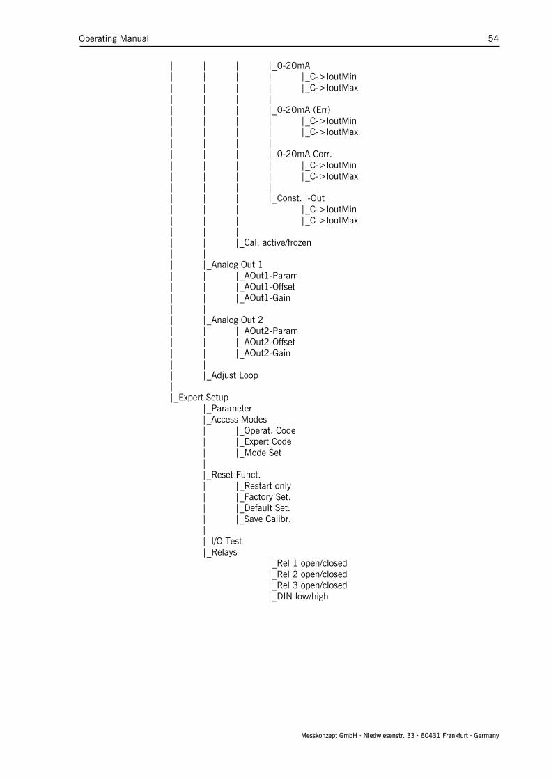
Operating Manual 54
Messkonzept GmbH · Niedwiesenstr. 33 · 60431 Frankfurt · Germany
| | | |_0-20mA | | | | |_C->IoutMin | | | | |_C->IoutMax | | | | | | | |_0-20mA (Err) | | | | |_C->IoutMin | | | | |_C->IoutMax | | | | | | | |_0-20mA Corr. | | | | |_C->IoutMin | | | | |_C->IoutMax | | | | | | | |_Const. I-Out | | | |_C->IoutMin | | | |_C->IoutMax | | | | | |_Cal. active/frozen | |
| |_Analog Out 1 | | |_AOut1-Param | | |_AOut1-Offset | | |_AOut1-Gain | |
| |_Analog Out 2 | | |_AOut2-Param | | |_AOut2-Offset | | |_AOut2-Gain | |
| |_Adjust Loop |
|_Expert Setup |_Parameter
|_Access Modes | |_Operat. Code | |_Expert Code | |_Mode Set | |_Reset Funct. | |_Restart only | |_Factory Set. | |_Default Set. | |_Save Calibr. | |_I/O Test |_Relays
|_Rel 1 open/closed |_Rel 2 open/closed |_Rel 3 open/closed |_DIN low/high