operating instructions io-link master with ethernet/ip interface … · 2018-09-05 · 8 ifm...
TRANSCRIPT

Operating Instructions
IO-Link Master with EtherNet/IP interface
DataLine
8 Ports
IP 65 / IP 66 / IP 67
AL1322
IO-Link: 1.1.2
ifm firmware: 2.1.28 or higher
LR DEVICE: 1.3.1.x or higher
English
7391
158
/ 0
1
0
5 / 2
018
2
ifm Operating Instructions IO-Link Master with EtherNet/IP interface DataLine 8 Ports IP 65 / IP 66 / IP 67 (AL1322) 05 / 2018
Content
Table of Contents
1 Preliminary note 5
1.1 Legal and copyright information ........................................................................................... 5 1.2 Purpose of the document ..................................................................................................... 5 1.3 Symbols and styles used ..................................................................................................... 6 1.4 Modification history .............................................................................................................. 6
2 Safety instructions 7
2.1 General ................................................................................................................................ 7 2.2 Required background knowledge ........................................................................................ 7 2.3 Safety symbols on the device .............................................................................................. 7 2.4 Tampering with the unit ........................................................................................................ 8
3 Intended use 9
3.1 Permitted use ....................................................................................................................... 9 3.2 Prohibited use ...................................................................................................................... 9
4 Function 10
4.1 Communication, parameter setting, evaluation .................................................................11 4.1.1 IO-Link ........................................................................................................................................ 11 4.1.2 EtherNet/IP ................................................................................................................................. 11 4.1.3 Internet of Things (IoT) ............................................................................................................... 11 4.1.4 Parameter setting ....................................................................................................................... 11 4.1.5 Visual indication ......................................................................................................................... 12
4.2 Digital inputs .......................................................................................................................12 4.3 IO-Link supply ....................................................................................................................12
5 Mounting 13
5.1 Mount the device ................................................................................................................13
6 Electrical connection 14
6.1 Remarks .............................................................................................................................14 6.2 EtherNet/IP ports................................................................................................................15 6.3 IoT port ...............................................................................................................................16 6.4 IO-Link ports .......................................................................................................................17
6.4.1 Input circuit ................................................................................................................................. 18 6.4.2 IO-Link circuits ............................................................................................................................ 18
6.5 Connect the device ............................................................................................................19
7 Operating and display elements 20
7.1 Overview ............................................................................................................................20 7.2 LED indicators ....................................................................................................................21
7.2.1 Status LEDs ............................................................................................................................... 21 7.2.2 Ethernet interface ....................................................................................................................... 21 7.2.3 IoT port ....................................................................................................................................... 22 7.2.4 Voltage supply ............................................................................................................................ 22 7.2.5 IO-Link ports (Class A) ............................................................................................................... 22
3
ifm Operating Instructions IO-Link Master with EtherNet/IP interface DataLine 8 Ports IP 65 / IP 66 / IP 67 (AL1322) 05 / 2018
Content
8 Configuration 23
8.1 LR DEVICE ........................................................................................................................24 8.1.1 Remarks ..................................................................................................................................... 25 8.1.2 IoT: Configure access rights ....................................................................................................... 26 8.1.3 IoT: Configure IP settings ........................................................................................................... 27 8.1.4 IoT: Configure the interface to the LR SMARTOBSERVER ....................................................... 28 8.1.5 Fieldbus: Configure the EtherNet/IP port .................................................................................... 29 8.1.6 IO-Link ports: Activate data transfer to the LR SMARTOBSERVER .......................................... 30 8.1.7 IO-Link ports: Configure operating mode.................................................................................... 31 8.1.8 IO-Link ports: Set the device validation and data storage .......................................................... 32 8.1.9 IO-Link Ports: Set fails-safe values ............................................................................................ 32 8.1.10 Info: Show device information .................................................................................................... 33 8.1.11 Firmware: Reset device to factory settings ................................................................................. 34 8.1.12 Firmware: Reboot the device ...................................................................................................... 34 8.1.13 Configure IO-Link devices .......................................................................................................... 35
8.2 IoT Core .............................................................................................................................36 8.2.1 Configure IoT interface ............................................................................................................... 36 8.2.2 Configure the fieldbus interface .................................................................................................. 38 8.2.3 Configure IO-Link ports .............................................................................................................. 39 8.2.4 Set application identification ....................................................................................................... 39 8.2.5 Read / write cyclic process data ................................................................................................. 39 8.2.6 Read diagnostic data .................................................................................................................. 40 8.2.7 Read device information ............................................................................................................. 40 8.2.8 Control IO-Link master ............................................................................................................... 41 8.2.9 Configure IO-Link devices .......................................................................................................... 41 8.2.10 Read information about IO-Link devices .................................................................................... 42 8.2.11 Examples .................................................................................................................................... 43 8.2.12 Programmers' notes ................................................................................................................... 47
8.3 EtherNet/IP .........................................................................................................................51 8.3.1 Registration of the EDS file ........................................................................................................ 51 8.3.2 Integrate the AL1322 into the EtherNet/IP project ...................................................................... 52 8.3.3 Set connection types .................................................................................................................. 52 8.3.4 Configure AL1322 ...................................................................................................................... 53 8.3.5 Configure IO-Link ports .............................................................................................................. 54 8.3.6 Configure IO-Link devices .......................................................................................................... 55 8.3.7 Read cyclic input data ................................................................................................................ 56 8.3.8 Write cyclic output data .............................................................................................................. 56 8.3.9 Read diagnostic and status information ..................................................................................... 57 8.3.10 EtherNet/IP: Programmers' notes ............................................................................................... 58
9 Operation 61
9.1 Firmware update ................................................................................................................61 9.2 Web interface: Read device and diagnostic information....................................................62 9.3 Replace IO-Link device ......................................................................................................63
10 Maintenance 64
11 Factory settings 65
12 Accessories 66
13 Appendix 67
13.1 Technical data ....................................................................................................................68 13.1.1 Application .................................................................................................................................. 68
4
ifm Operating Instructions IO-Link Master with EtherNet/IP interface DataLine 8 Ports IP 65 / IP 66 / IP 67 (AL1322) 05 / 2018
Content
13.1.2 Electrical data ............................................................................................................................. 68 13.1.3 Inputs / outputs ........................................................................................................................... 68 13.1.4 Inputs.......................................................................................................................................... 69 13.1.5 Outputs ....................................................................................................................................... 69 13.1.6 Interfaces .................................................................................................................................... 69 13.1.7 Operating conditions .................................................................................................................. 69 13.1.8 Approvals / tests ......................................................................................................................... 70 13.1.9 Mechanical data ......................................................................................................................... 70 13.1.10 Electrical connection .................................................................................................................. 71
13.2 EtherNet/IP .........................................................................................................................72 13.2.1 Supported connection types ....................................................................................................... 72 13.2.2 Parameter data ........................................................................................................................... 73 13.2.3 Cyclic data .................................................................................................................................. 76 13.2.4 Acyclic data ................................................................................................................................ 86
13.3 ifm IoT Core .....................................................................................................................117 13.3.1 Overview: IoT profile ................................................................................................................ 118 13.3.2 Overview: IoT types .................................................................................................................. 121 13.3.3 Overview: IoT services ............................................................................................................. 122
14 Index 129
5
ifm Operating Instructions IO-Link Master with EtherNet/IP interface DataLine 8 Ports IP 65 / IP 66 / IP 67 (AL1322) 05 / 2018
Preliminary note Legal and copyright information
1 Preliminary note
Legal and copyright information ............................................................................................................ 5 Purpose of the document ...................................................................................................................... 5 Symbols and styles used ....................................................................................................................... 6 Modification history ................................................................................................................................ 6
14801 >
1.1 Legal and copyright information 1631
© All rights reserved by ifm electronic gmbh. No part of this manual may be reproduced and used without the consent of ifm electronic gmbh.
All product names, pictures, companies or other brands used on our pages are the property of the respective rights owners:
AS-i is the property of the AS-International Association, (→ www.as-interface.net)
CAN is the property of the CiA (CAN in Automation e.V.), Germany (→ www.can-cia.org)
CODESYS™ is the property of the 3S – Smart Software Solutions GmbH, Germany (→ www.codesys.com)
DeviceNet™ is the property of the ODVA™ (Open DeviceNet Vendor Association), USA (→ www.odva.org)
EtherNet/IP® is the property of the →ODVA™
EtherCAT® is a registered trade mark and patented technology, licensed by Beckhoff Automation GmbH, Germany
IO-Link® (→ www.io-link.com) is the property of the →PROFIBUS Nutzerorganisation e.V., Germany
ISOBUS is the property of the AEF – Agricultural Industry Electronics Foundation e.V., Deutschland (→ www.aef-online.org)
Microsoft® is the property of the Microsoft Corporation, USA (→ www.microsoft.com)
PROFIBUS® is the property of the PROFIBUS Nutzerorganisation e.V., Germany (→ www.profibus.com)
PROFINET® is the property of the →PROFIBUS Nutzerorganisation e.V., Germany
Windows® is the property of the →Microsoft Corporation, USA >
1.2 Purpose of the document 22044
This document is only for device types "IO-Link master - EtherNet/IP gateway (DataLine) 8 port IP 65 / IP 66 / IP 67" (art. no.: AL1322).
It is part of the device and contains information about the correct handling of the product.
► Read this document before using the device.
► Keep this document during the service life of the device.
6
ifm Operating Instructions IO-Link Master with EtherNet/IP interface DataLine 8 Ports IP 65 / IP 66 / IP 67 (AL1322) 05 / 2018
Preliminary note Symbols and styles used
1.3 Symbols and styles used 15989
WARNING
Death or serious irreversible injuries may result.
CAUTION
Slight reversible injuries may result.
NOTICE
Property damage is to be expected or may result.
Important note Non-compliance can result in malfunction or interference
Information Supplementary note
► ... Request for action
> ... Reaction, result
→ ... "see"
abc Cross-reference
123 0x123 0b010
Decimal number Hexadecimal number Binary number
[...] Designation of pushbuttons, buttons or indications
>
1.4 Modification history 8700
Version Topic Date
00 New creation of document 11 / 2017
01 Update to firmware 2.1.28 Added: Support of different EtherNet/IP connection types Added: Support of different configuration mode (top down, independent) Added: Event description
05 / 2018
7
ifm Operating Instructions IO-Link Master with EtherNet/IP interface DataLine 8 Ports IP 65 / IP 66 / IP 67 (AL1322) 05 / 2018
Safety instructions General
2 Safety instructions
General .................................................................................................................................................. 7 Required background knowledge .......................................................................................................... 7 Safety symbols on the device ................................................................................................................ 7 Tampering with the unit ......................................................................................................................... 8
213 >
2.1 General 22068
The plant manufacturer is responsible for the safety of the plant in which the device is installed.
If the device is used in a way that is not intended by the manufacturer, the protection supported by the device may be impaired.
Non-observance of the instructions, operation which is not in accordance with use as prescribed below, wrong installation or incorrect handling can affect the safety of operators and machinery.
► Observe these operating instructions.
► Adhere to the warning notes on the product.
>
2.2 Required background knowledge 22046
This document is intended for specialists. Specialists are people who, based on their relevant training and experience, are capable of identifying risks and avoiding potential hazards that may be caused during operation or maintenance of the product.
The document contains information about the correct handling of the product. >
2.3 Safety symbols on the device 15021
General warning Observe instructions in chapter "Electrical connection" (→ Electrical connection (→ p. 14))!
8
ifm Operating Instructions IO-Link Master with EtherNet/IP interface DataLine 8 Ports IP 65 / IP 66 / IP 67 (AL1322) 05 / 2018
Safety instructions Tampering with the unit
2.4 Tampering with the unit 11242
WARNING
Tampering with the units can affect the safety of operators and machinery!
Tampering with the units is not allowed. In case of non-compliance our liability and warranty expire.
► Do not open the devices!
► Do not insert any objects into the devices!
► Prevent metal foreign bodies from penetrating!
9
ifm Operating Instructions IO-Link Master with EtherNet/IP interface DataLine 8 Ports IP 65 / IP 66 / IP 67 (AL1322) 05 / 2018
Intended use Permitted use
3 Intended use
Permitted use ........................................................................................................................................ 9 Prohibited use ........................................................................................................................................ 9
18761 >
3.1 Permitted use 22052
The IO-Link master serves as a gateway between intelligent IO-Link devices and the fieldbus. The device is designed for use without a control cabinet in the plant construction. >
3.2 Prohibited use 22053
The device may not be used beyond the limits of the technical data (→ Technical data (→ p. 68))!

10
ifm Operating Instructions IO-Link Master with EtherNet/IP interface DataLine 8 Ports IP 65 / IP 66 / IP 67 (AL1322) 05 / 2018
Function Prohibited use
4 Function
Communication, parameter setting, evaluation ................................................................................... 11 Digital inputs ........................................................................................................................................ 12 IO-Link supply ...................................................................................................................................... 12
7482
11
ifm Operating Instructions IO-Link Master with EtherNet/IP interface DataLine 8 Ports IP 65 / IP 66 / IP 67 (AL1322) 05 / 2018
Function Communication, parameter setting, evaluation
4.1 Communication, parameter setting, evaluation
IO-Link ................................................................................................................................................. 11 EtherNet/IP .......................................................................................................................................... 11 Internet of Things (IoT) ........................................................................................................................ 11 Parameter setting ................................................................................................................................ 11 Visual indication ................................................................................................................................... 12
7485 >
4.1.1 IO-Link 7773
The device offers the following IO-Link functions:
IO-Link master (IO-Link revision 1.0 and 1.1)
8 IO-Link ports for connection of IO-Link devices
Provision of process data of the connected IO-Link devices for LR SMARTOBSERVER monitoring software (→ www.ifm.com)
>
4.1.2 EtherNet/IP 2259
The device offers the following EtherNet/IP functions:
Provision of the functions of a EtherNet/IP Device
2 port switch for access to the EtherNet/IP interface (X21/X22)
Gateway for transmission of the process and parameter data between the connected IO-Link devices and the higher-level EtherNet/IP controller
>
4.1.3 Internet of Things (IoT) 8355
The device has an Ethernet port (X23) for Internet-of-Things applications. The interface allows separate access from IT networks to parameters, process and monitoring data of the IO-Link master and the connected IO-Link devices. Different protocols (e.g. TCP/IP JSON) are supported. >
4.1.4 Parameter setting 7284
The device provides the following configuration options:
Parameter setting of the IO-Link master of the AL1322 with LR DEVICE parameter setting software, EtherNet/IP projection software or ifm IoT-Core services.
Parameter setting of the connected IO-Link devices (sensors, actuators) with LR DEVICE parameter setting software, EtherNet/IP projection software or ifm IoT-Core services
Storage of parameter sets of the connected IO-Link devices for automatic recovery (data storage)
12
ifm Operating Instructions IO-Link Master with EtherNet/IP interface DataLine 8 Ports IP 65 / IP 66 / IP 67 (AL1322) 05 / 2018
Function Digital inputs
4.1.5 Visual indication 7772
The device has the following visual indicators:
Status and error indication of the gateway, of the EtherNet/IP connection and of the system
Status display of the voltage supply
Status and activity display of the Ethernet connection
Status, error and short circuit/overload indication of the IO-Link ports >
4.2 Digital inputs 7584
The device has 8 additional digital inputs (type 2 according to EN 61131-2).
The digital inputs are on pin 2 of the IO-Link ports X01 ... X08.
All inputs refer to the potential of the device supply (pin 3). >
4.3 IO-Link supply 7623
The device has 8 supplies for IO-Link devices.
The IO-Link ports X01...X08 are ports class A.
Every supply provides short circuit monitoring.
The device ensures fire protection for the connected IO-Link devices by providing a power-restricted circuit at the IO-Link ports (according to IEC61010-1 and Class 2 according to UL1310).
13
ifm Operating Instructions IO-Link Master with EtherNet/IP interface DataLine 8 Ports IP 65 / IP 66 / IP 67 (AL1322) 05 / 2018
Mounting Mount the device
5 Mounting
Mount the device ................................................................................................................................. 13 22016
>
5.1 Mount the device 15540
► Disconnect the system from power before installation.
► For installation choose a flat mounting surface.
► Please observe the maximum tightening torque.
► Fix the unit to the mounting surface using 2 M5 mounting screws and washers.
Tightening torque: 1.8 Nm
► Ground the unit via the two mounting screws of the upper mounting lugs.
14
ifm Operating Instructions IO-Link Master with EtherNet/IP interface DataLine 8 Ports IP 65 / IP 66 / IP 67 (AL1322) 05 / 2018
Electrical connection Remarks
6 Electrical connection
Remarks .............................................................................................................................................. 14 EtherNet/IP ports ................................................................................................................................. 15 IoT port ................................................................................................................................................ 16 IO-Link ports ........................................................................................................................................ 17 Connect the device .............................................................................................................................. 19
22017 >
6.1 Remarks 18076
A qualified electrician must connect the unit.
► Observe the national and international regulations for the installation of electrical equipment.
Device is only suitable for operation on SELV/PELV voltages.
► Observe the information concerning IO-Link circuits (→ IO-Link circuits (→ p. 18))!
The device contains components that can be damaged or destroyed by electrostatic discharge (ESD).
► Observe the required safety measures against electrostatic discharge!
The IP rating depends on the individual protection ratings of the unit, the applied connection elements and the corresponding protective covers.
► For UL applications: For connecting the device and the IO-Link devices use UL certificated cables of category CYJV or PVVA with a minimum temperature rating of 100°C.
► Depending on the mounting conditions, cables must be provided with a strain relief to avoid unacceptable loads on the mounting points and M12 connections.
► Make sure that the M12 connection parts are correctly seated and mounted correctly. The specified protection rating can not be guaranteed if this is not observed.
Wiring: → Technical data (→ p. 68)
The communication interfaces are seperated from the device supply according to EN61010-1 considering basis isolation as secondary circuit with maximum 30 V DC derived from the applied voltage up to 300 V of overvoltage category II. The communication interfaces are designed for a network environment 0 according to IEC TR62102.
15
ifm Operating Instructions IO-Link Master with EtherNet/IP interface DataLine 8 Ports IP 65 / IP 66 / IP 67 (AL1322) 05 / 2018
Electrical connection EtherNet/IP ports
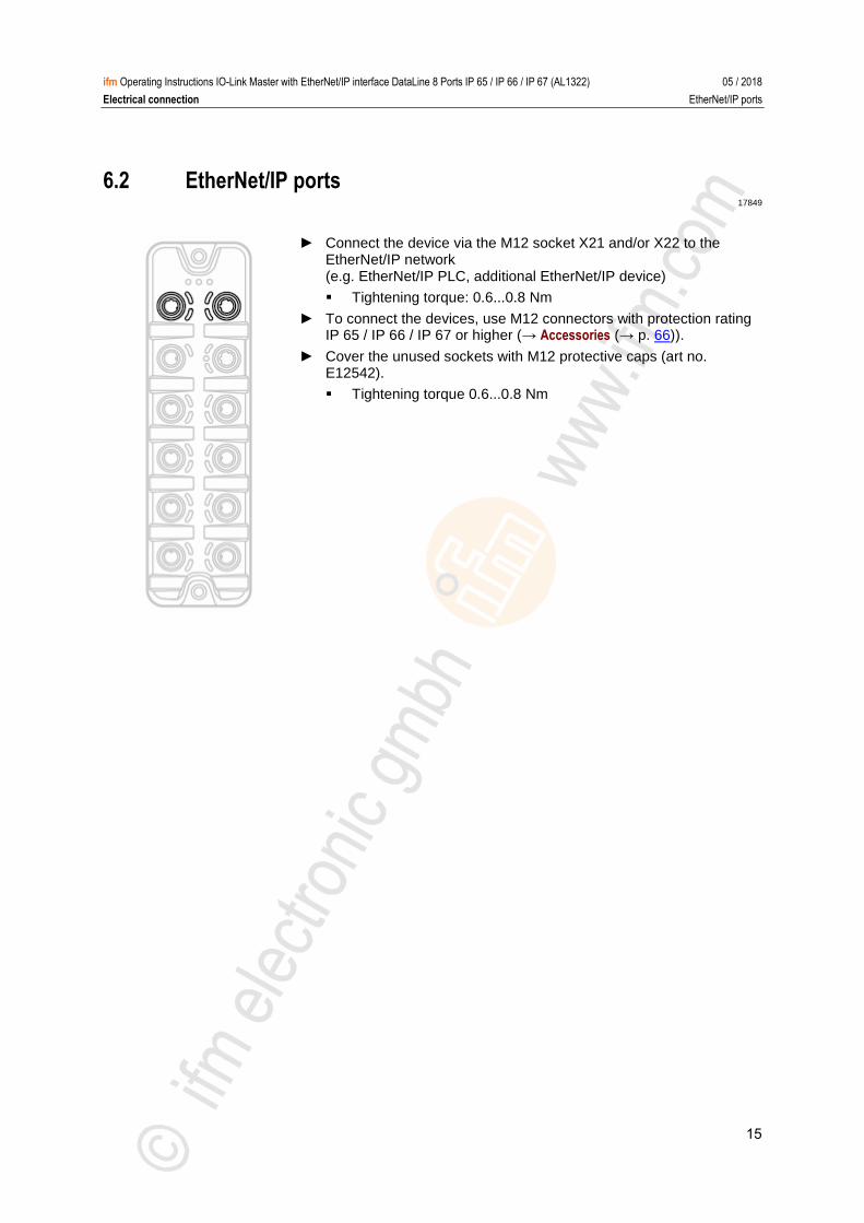
6.2 EtherNet/IP ports 17849
► Connect the device via the M12 socket X21 and/or X22 to the EtherNet/IP network (e.g. EtherNet/IP PLC, additional EtherNet/IP device)
Tightening torque: 0.6...0.8 Nm
► To connect the devices, use M12 connectors with protection rating IP 65 / IP 66 / IP 67 or higher (→ Accessories (→ p. 66)).
► Cover the unused sockets with M12 protective caps (art no. E12542).
Tightening torque 0.6...0.8 Nm
16
ifm Operating Instructions IO-Link Master with EtherNet/IP interface DataLine 8 Ports IP 65 / IP 66 / IP 67 (AL1322) 05 / 2018
Electrical connection IoT port
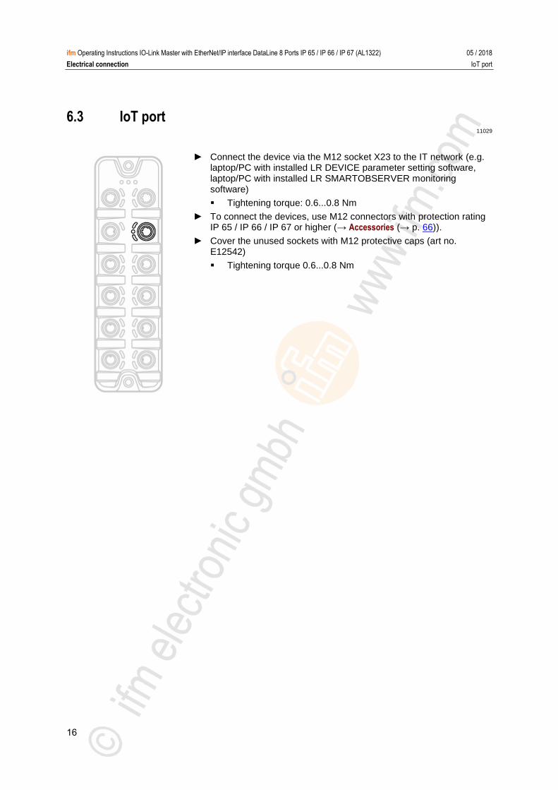
6.3 IoT port 11029
► Connect the device via the M12 socket X23 to the IT network (e.g. laptop/PC with installed LR DEVICE parameter setting software, laptop/PC with installed LR SMARTOBSERVER monitoring software)
Tightening torque: 0.6...0.8 Nm
► To connect the devices, use M12 connectors with protection rating IP 65 / IP 66 / IP 67 or higher (→ Accessories (→ p. 66)).
► Cover the unused sockets with M12 protective caps (art no. E12542)
Tightening torque 0.6...0.8 Nm
17
ifm Operating Instructions IO-Link Master with EtherNet/IP interface DataLine 8 Ports IP 65 / IP 66 / IP 67 (AL1322) 05 / 2018
Electrical connection IO-Link ports
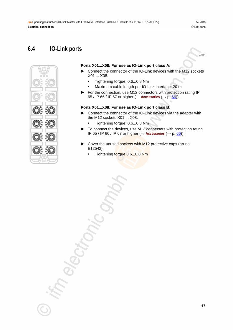
6.4 IO-Link ports 22684
Ports X01...X08: For use as IO-Link port class A:
► Connect the connector of the IO-Link devices with the M12 sockets X01 ... X08.
Tightening torque: 0.6...0.8 Nm
Maximum cable length per IO-Link interface: 20 m
► For the connection, use M12 connectors with protection rating IP 65 / IP 66 / IP 67 or higher (→ Accessories (→ p. 66)).
Ports X01...X08: For use as IO-Link port class B:
► Connect the connector of the IO-Link devices via the adapter with the M12 sockets X01 ... X08.
Tightening torque: 0.6...0.8 Nm
► To connect the devices, use M12 connectors with protection rating IP 65 / IP 66 / IP 67 or higher (→ Accessories (→ p. 66)).
► Cover the unused sockets with M12 protective caps (art no. E12542).
Tightening torque 0.6...0.8 Nm
18
ifm Operating Instructions IO-Link Master with EtherNet/IP interface DataLine 8 Ports IP 65 / IP 66 / IP 67 (AL1322) 05 / 2018
Electrical connection IO-Link ports
6.4.1 Input circuit 18629
The inputs of the ports X01...X08 (pin 2) provide a type 2 behaviour according to standard EN61131-2, the connected electronics must be rated for this electrically. >
6.4.2 IO-Link circuits 11616
The IO-Link interfaces of the device meet the requirements of the IO-Link specification 1.0 to 1.1.2.
The connected IO-Link devices may only be supplied via the AL1322.
Exception: Connection of IO-Link devices to ports X01...X08 via suitable connection technology for port class B operation (→ IO-Link ports (→ p. 17)): The external supply for port class B operation must be galvanically separeted from the circuit of the AL1322 by assuring basic isolation (according to EN61010-1, secondary circuit with maximum 30 V DC derived from applied voltage up to 300 V of overvoltage category II)!
The isolation must be done both for IO-Link devices and for the connection technology.
NOTICE
Risk of material damage
If the requirements of galvanic separation of the circuits are not observed, the fire protection of the device can not be assured.
► Observe the requirements of the electrical connection of IO-Link devices for port class B operation!
Further information: → Technical data (→ p. 68)
19
ifm Operating Instructions IO-Link Master with EtherNet/IP interface DataLine 8 Ports IP 65 / IP 66 / IP 67 (AL1322) 05 / 2018
Electrical connection Connect the device
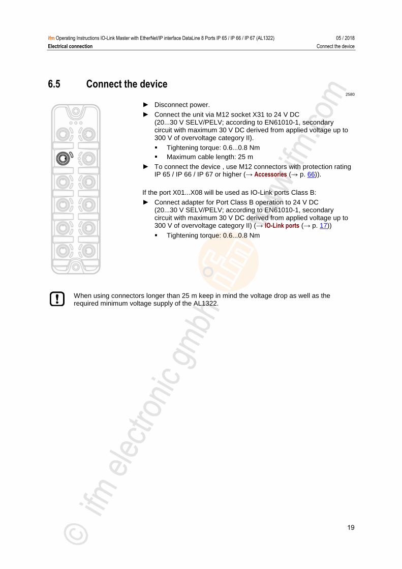
6.5 Connect the device 2580
► Disconnect power.
► Connect the unit via M12 socket X31 to 24 V DC (20...30 V SELV/PELV; according to EN61010-1, secondary circuit with maximum 30 V DC derived from applied voltage up to 300 V of overvoltage category II).
Tightening torque: 0.6...0.8 Nm
Maximum cable length: 25 m
► To connect the device , use M12 connectors with protection rating IP 65 / IP 66 / IP 67 or higher (→ Accessories (→ p. 66)).
If the port X01...X08 will be used as IO-Link ports Class B:
► Connect adapter for Port Class B operation to 24 V DC (20...30 V SELV/PELV; according to EN61010-1, secondary circuit with maximum 30 V DC derived from applied voltage up to 300 V of overvoltage category II) (→ IO-Link ports (→ p. 17))
Tightening torque: 0.6...0.8 Nm
When using connectors longer than 25 m keep in mind the voltage drop as well as the required minimum voltage supply of the AL1322.
20
ifm Operating Instructions IO-Link Master with EtherNet/IP interface DataLine 8 Ports IP 65 / IP 66 / IP 67 (AL1322) 05 / 2018
Operating and display elements Overview
7 Operating and display elements
Overview .............................................................................................................................................. 20 LED indicators ..................................................................................................................................... 21
5440 >
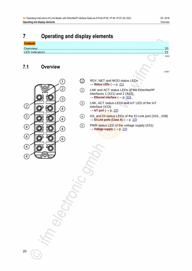
7.1 Overview 17857
RDY, NET and MOD status LEDs → Status LEDs (→ p. 21)
LNK and ACT status LEDs of the EtherNet/IP interfaces 1 (X21) and 2 (X22) → Ethernet interface (→ p. 21)
LNK, ACT status-LEDs and IoT LED of the IoT interface (X23) → IoT port (→ p. 22)
IOL and DI status-LEDs of the IO-Link port (X01...X08) → IO-Link ports (Class A) (→ p. 22)
PWR status LED of the voltage supply (X31) → Voltage supply (→ p. 22)
1
2
3
4
5
21
ifm Operating Instructions IO-Link Master with EtherNet/IP interface DataLine 8 Ports IP 65 / IP 66 / IP 67 (AL1322) 05 / 2018
Operating and display elements LED indicators
7.2 LED indicators 22024
The device only has the following LED indicators: >
7.2.1 Status LEDs 7707
The RDY LED indicates the status of the gateway.
The NET LED (Network Status) indicates the status of the network.
The MOD LED (Module Status) indicates the status of the EtherNet/IP module.
Status LED Description
RDY green on Gateway functions properly
flashes 1 Hz Error
flashes 5 Hz Firmware update
off Gateway does not function; Device reboots
NET green on Connection with the EtherNet/IP PLC
off No IP address
red on IP address is used twice
flashes No connection with the EtherNet/IP PLC
MOD green on No error
off Voltage too low
red on Module failed
flashes Configuration of the module has been changed
>
7.2.2 Ethernet interface 22027
Each Ethernet interface (X21, X22) has 2 LEDs (LNK and ACT). The LEDs indicate the status of the Ethernet connection.
Status LED Description
LNK green on Ethernet connection established
off No Ethernet connection
ACT yellow flashes Data is transmitted via the Ethernet interface.
off No data transmission
22
ifm Operating Instructions IO-Link Master with EtherNet/IP interface DataLine 8 Ports IP 65 / IP 66 / IP 67 (AL1322) 05 / 2018
Operating and display elements LED indicators
7.2.3 IoT port 7722
The IoT port (X23) has the 3 LNK, ACT and IoT LEDs. The LEDs indicate the status of the Ethernet connection and the device identification.
Status LED Description
LNK green on Ethernet connection established
off No Ethernet connection
ACT yellow flashes Data is transmitted via the Ethernet interface.
off No data transmission
IoT green flashes Device identification active
>
7.2.4 Voltage supply 22026
The interface for voltage supply (X31) has the LED that is marked as US. The LED indicates the status of the voltage supply.
Status LED Description
US green on The supply voltage Us is applied.
off No supply voltage is applied or the applied supply voltage is too low.
>
7.2.5 IO-Link ports (Class A) 22029
Each IO-Link port Class A (X01 ... X08) has 2 LEDs marked as IOL and DI. The LEDs indicate the status of the IO-Link port.
Status LED Description
IOL yellow on Interface configured as DI/DO: pin 4 (C/Q) =ON
off Interface configured as DI/DO: pin 4 (C/Q) = OFF
green on IO-Link transmission functions properly
flashes 1 Hz Interface configured as IO-Link, but no IO-Link transmission
red on Short circuit or overload in supply voltage
flashes 1 Hz Transmission error
DI yellow on Digital input: pin 2 (DI) = ON
off Digital input : pin 2 (DI) = OFF

23
ifm Operating Instructions IO-Link Master with EtherNet/IP interface DataLine 8 Ports IP 65 / IP 66 / IP 67 (AL1322) 05 / 2018
Configuration LED indicators
8 Configuration
LR DEVICE .......................................................................................................................................... 24 IoT Core ............................................................................................................................................... 36 EtherNet/IP .......................................................................................................................................... 51
22367
24
ifm Operating Instructions IO-Link Master with EtherNet/IP interface DataLine 8 Ports IP 65 / IP 66 / IP 67 (AL1322) 05 / 2018
Configuration LR DEVICE
8.1 LR DEVICE
Remarks .............................................................................................................................................. 25 IoT: Configure access rights ................................................................................................................ 26 IoT: Configure IP settings .................................................................................................................... 27 IoT: Configure the interface to the LR SMARTOBSERVER ............................................................... 28 Fieldbus: Configure the EtherNet/IP port ............................................................................................ 29 IO-Link ports: Activate data transfer to the LR SMARTOBSERVER .................................................. 30 IO-Link ports: Configure operating mode ............................................................................................ 31 IO-Link ports: Set the device validation and data storage .................................................................. 32 IO-Link Ports: Set fails-safe values ..................................................................................................... 32 Info: Show device information ............................................................................................................. 33 Firmware: Reset device to factory settings ......................................................................................... 34 Firmware: Reboot the device .............................................................................................................. 34 Configure IO-Link devices ................................................................................................................... 35
22822
On delivery, the AL1322 is configured with the factory settings (→ Factory settings (→ p. 65)).
Required software: LR DEVICE (1.3.1.x or higher) (art.-no.: QA0011/QA0012)
25
ifm Operating Instructions IO-Link Master with EtherNet/IP interface DataLine 8 Ports IP 65 / IP 66 / IP 67 (AL1322) 05 / 2018
Configuration LR DEVICE
8.1.1 Remarks
Offline parameter setting ..................................................................................................................... 25 VPN connection ................................................................................................................................... 25
22369 >
Offline parameter setting 22405
The AL1322 supports the offline parameter setting. In this context, the user creates and stores a configuration for the IO-Link master and the connected IO-Link devices without being connected to the AL1322 (OFFLINE mode). The configuration created in this way can be stored as a file (*.lrp) and loaded to the AL1322 and activated at a later date.
Further information about offline parameter setting: → Operating instructions LR DEVICE
>
VPN connection 22762
An active VPN connection blocks the access of the parameter setting software LR DEVICE to the EtherNet/IP interface of the AL1322.
► Deactivate the VPN connection in order to be able to access the AL1322 with the LR DEVICE.
26
ifm Operating Instructions IO-Link Master with EtherNet/IP interface DataLine 8 Ports IP 65 / IP 66 / IP 67 (AL1322) 05 / 2018
Configuration LR DEVICE
8.1.2 IoT: Configure access rights 16555
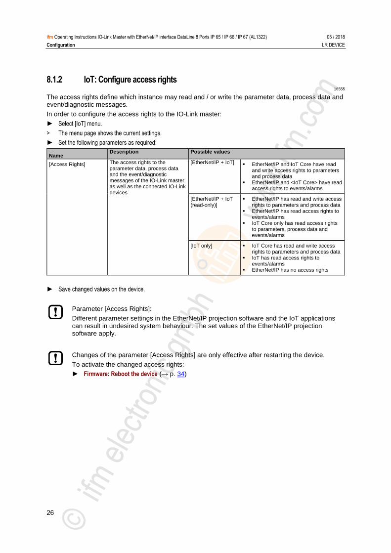
The access rights define which instance may read and / or write the parameter data, process data and event/diagnostic messages.
In order to configure the access rights to the IO-Link master:
► Select [IoT] menu.
> The menu page shows the current settings.
► Set the following parameters as required:
Name Description Possible values
[Access Rights] The access rights to the parameter data, process data and the event/diagnostic messages of the IO-Link master as well as the connected IO-Link devices
[EtherNet/IP + IoT] EtherNet/IP and IoT Core have read
and write access rights to parameters and process data
EtherNet/IP and <IoT Core> have read access rights to events/alarms
[EtherNet/IP + IoT (read-only)]
EtherNet/IP has read and write access rights to parameters and process data
EtherNet/IP has read access rights to events/alarms
IoT Core only has read access rights to parameters, process data and events/alarms
[IoT only] IoT Core has read and write access rights to parameters and process data
IoT has read access rights to events/alarms
EtherNet/IP has no access rights
► Save changed values on the device.
Parameter [Access Rights]:
Different parameter settings in the EtherNet/IP projection software and the IoT applications can result in undesired system behaviour. The set values of the EtherNet/IP projection software apply.
Changes of the parameter [Access Rights] are only effective after restarting the device.
To activate the changed access rights:
► Firmware: Reboot the device (→ p. 34)
27
ifm Operating Instructions IO-Link Master with EtherNet/IP interface DataLine 8 Ports IP 65 / IP 66 / IP 67 (AL1322) 05 / 2018
Configuration LR DEVICE
8.1.3 IoT: Configure IP settings 17713
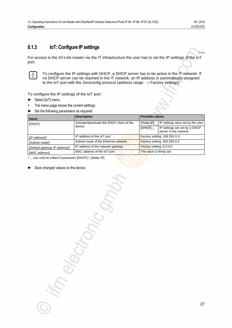
For access to the IO-Link master via the IT infrastructure the user has to set the IP settings of the IoT port.
To configure the IP settings with DHCP, a DHCP server has to be active in the IT network. If no DHCP server can be reached in the IT network, an IP address is automatically assigned to the IoT port with the Zeroconfig protocol (address range: → Factory settings).
To configure the IP settings of the IoT port:
► Select [IoT] menu.
> The menu page shows the current settings.
► Set the following parameters as required:
Name Description Possible values
[DHCP] Activate/deactivate the DHCP client of the device
[Static IP] IP settings were set by the user
[DHCP] IP settings are set by a DHCP server in the network.
[IP address]* IP address of the IoT port Factory setting: 169.254.X.X
[Subnet mask]* Subnet mask of the Ethernet network Factory setting: 255.255.0.0
[Default gateway IP address]* IP address of the network gateway Factory setting: 0.0.0.0
[MAC address] MAC address of the IoT port The value is firmly set.
* ... can only be edited if parameter [DHCP] = [Static IP]
► Save changed values on the device.
28
ifm Operating Instructions IO-Link Master with EtherNet/IP interface DataLine 8 Ports IP 65 / IP 66 / IP 67 (AL1322) 05 / 2018
Configuration LR DEVICE
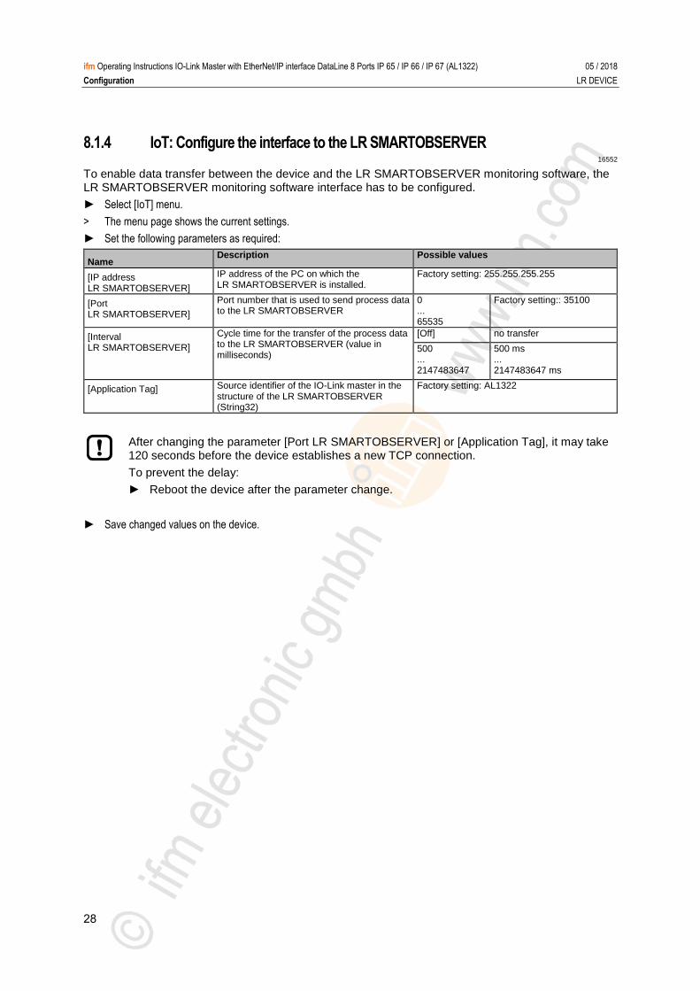
8.1.4 IoT: Configure the interface to the LR SMARTOBSERVER 16552
To enable data transfer between the device and the LR SMARTOBSERVER monitoring software, the LR SMARTOBSERVER monitoring software interface has to be configured.
► Select [IoT] menu.
> The menu page shows the current settings.
► Set the following parameters as required:
Name Description Possible values
[IP address LR SMARTOBSERVER]
IP address of the PC on which the LR SMARTOBSERVER is installed.
Factory setting: 255.255.255.255
[Port LR SMARTOBSERVER]
Port number that is used to send process data to the LR SMARTOBSERVER
0 ... 65535
Factory setting:: 35100
[Interval LR SMARTOBSERVER]
Cycle time for the transfer of the process data to the LR SMARTOBSERVER (value in milliseconds)
[Off] no transfer
500 ... 2147483647
500 ms ... 2147483647 ms
[Application Tag] Source identifier of the IO-Link master in the structure of the LR SMARTOBSERVER (String32)
Factory setting: AL1322
After changing the parameter [Port LR SMARTOBSERVER] or [Application Tag], it may take 120 seconds before the device establishes a new TCP connection.
To prevent the delay:
► Reboot the device after the parameter change.
► Save changed values on the device.
29
ifm Operating Instructions IO-Link Master with EtherNet/IP interface DataLine 8 Ports IP 65 / IP 66 / IP 67 (AL1322) 05 / 2018
Configuration LR DEVICE
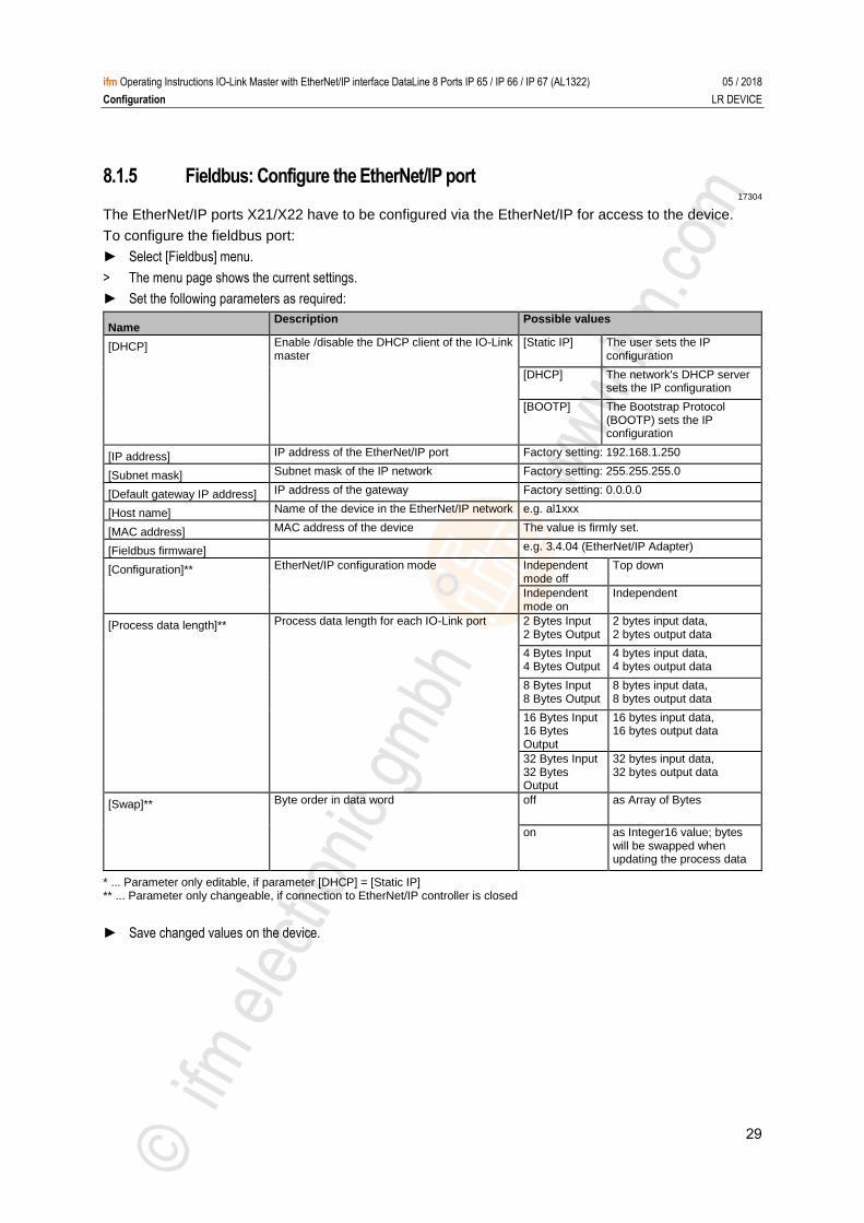
8.1.5 Fieldbus: Configure the EtherNet/IP port 17304
The EtherNet/IP ports X21/X22 have to be configured via the EtherNet/IP for access to the device.
To configure the fieldbus port:
► Select [Fieldbus] menu.
> The menu page shows the current settings.
► Set the following parameters as required:
Name Description Possible values
[DHCP] Enable /disable the DHCP client of the IO-Link master
[Static IP] The user sets the IP configuration
[DHCP] The network's DHCP server sets the IP configuration
[BOOTP] The Bootstrap Protocol (BOOTP) sets the IP configuration
[IP address] IP address of the EtherNet/IP port Factory setting: 192.168.1.250
[Subnet mask] Subnet mask of the IP network Factory setting: 255.255.255.0
[Default gateway IP address] IP address of the gateway Factory setting: 0.0.0.0
[Host name] Name of the device in the EtherNet/IP network e.g. al1xxx
[MAC address] MAC address of the device The value is firmly set.
[Fieldbus firmware] e.g. 3.4.04 (EtherNet/IP Adapter)
[Configuration]** EtherNet/IP configuration mode Independent mode off
Top down
Independent mode on
Independent
[Process data length]** Process data length for each IO-Link port 2 Bytes Input 2 Bytes Output
2 bytes input data, 2 bytes output data
4 Bytes Input 4 Bytes Output
4 bytes input data, 4 bytes output data
8 Bytes Input 8 Bytes Output
8 bytes input data, 8 bytes output data
16 Bytes Input 16 Bytes Output
16 bytes input data, 16 bytes output data
32 Bytes Input 32 Bytes Output
32 bytes input data, 32 bytes output data
[Swap]** Byte order in data word off as Array of Bytes
on as Integer16 value; bytes will be swapped when updating the process data
* ... Parameter only editable, if parameter [DHCP] = [Static IP] ** ... Parameter only changeable, if connection to EtherNet/IP controller is closed
► Save changed values on the device.
30
ifm Operating Instructions IO-Link Master with EtherNet/IP interface DataLine 8 Ports IP 65 / IP 66 / IP 67 (AL1322) 05 / 2018
Configuration LR DEVICE
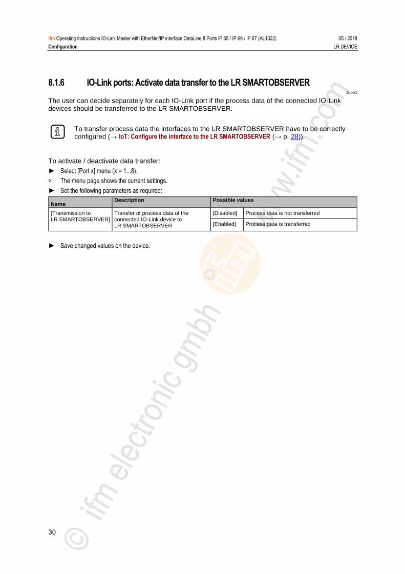
8.1.6 IO-Link ports: Activate data transfer to the LR SMARTOBSERVER 16551
The user can decide separately for each IO-Link port if the process data of the connected IO-Link devices should be transferred to the LR SMARTOBSERVER.
To transfer process data the interfaces to the LR SMARTOBSERVER have to be correctly configured (→ IoT: Configure the interface to the LR SMARTOBSERVER (→ p. 28)).
To activate / deactivate data transfer:
► Select [Port x] menu (x = 1...8).
> The menu page shows the current settings.
► Set the following parameters as required:
Name Description Possible values
[Transmission to LR SMARTOBSERVER]
Transfer of process data of the connected IO-Link device to LR SMARTOBSERVER
[Disabled] Process data is not transferred
[Enabled] Process data is transferred
► Save changed values on the device.
31
ifm Operating Instructions IO-Link Master with EtherNet/IP interface DataLine 8 Ports IP 65 / IP 66 / IP 67 (AL1322) 05 / 2018
Configuration LR DEVICE
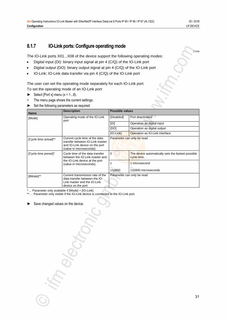
8.1.7 IO-Link ports: Configure operating mode 17439
The IO-Link ports X01...X08 of the device support the following operating modes:
Digital input (DI): binary input signal at pin 4 (C/Q) of the IO-Link port
Digital output (DO): binary output signal at pin 4 (C/Q) of the IO-Link port
IO-Link: IO-Link data transfer via pin 4 (C/Q) of the IO-Link port
The user can set the operating mode separately for each IO-Link port.
To set the operating mode of an IO-Link port:
► Select [Port x] menu (x = 1...8).
> The menu page shows the current settings.
► Set the following parameters as required:
Name Description Possible values
[Mode] Operating mode of the IO-Link port
[Disabled] Port deactivated
[DI] Operation as digital input
[DO] Operation as digital output
[IO-Link] Operation as IO-Link interface
[Cycle time actual]** Current cycle time of the data transfer between IO-Link master and IO-Link device on the port (value in microseconds)
Parameter can only be read
[Cycle time preset]* Cycle time of the data transfer between the IO-Link master and the IO-Link device at the port (value in microseconds)
0 The device automatically sets the fastest possible cycle time.
1 ... 132800
1 microsecond ... 132800 microseconds
[Bitrate]** Current transmission rate of the data transfer between the IO-Link master and the IO-Link device on the port
Parameter can only be read
* ... Parameter only available if [Mode] = [IO-Link] ** ... Parameter only visible if the IO-Link device is connected to the IO-Link port.
► Save changed values on the device.
32
ifm Operating Instructions IO-Link Master with EtherNet/IP interface DataLine 8 Ports IP 65 / IP 66 / IP 67 (AL1322) 05 / 2018
Configuration LR DEVICE
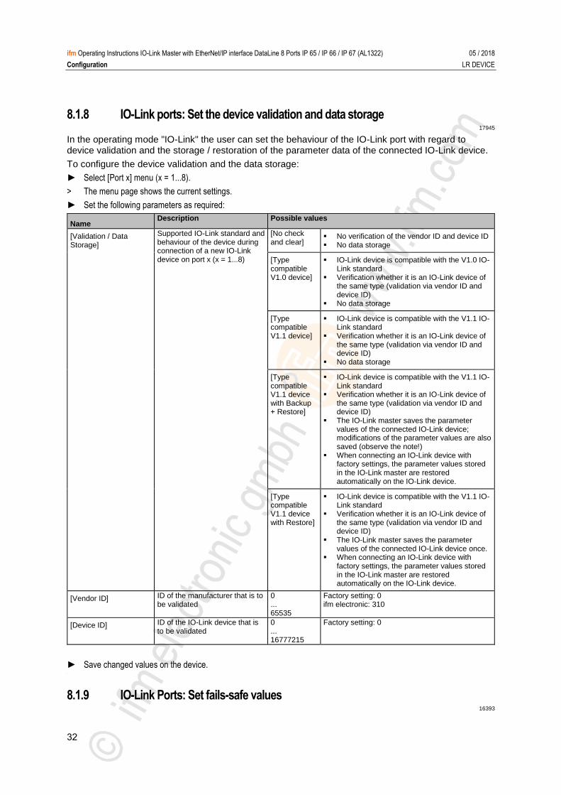
8.1.8 IO-Link ports: Set the device validation and data storage 17945
In the operating mode "IO-Link" the user can set the behaviour of the IO-Link port with regard to device validation and the storage / restoration of the parameter data of the connected IO-Link device.
To configure the device validation and the data storage:
► Select [Port x] menu (x = 1...8).
> The menu page shows the current settings.
► Set the following parameters as required:
Name Description Possible values
[Validation / Data Storage]
Supported IO-Link standard and behaviour of the device during connection of a new IO-Link device on port x (x = 1...8)
[No check and clear]
No verification of the vendor ID and device ID No data storage
[Type compatible V1.0 device]
IO-Link device is compatible with the V1.0 IO-Link standard
Verification whether it is an IO-Link device of the same type (validation via vendor ID and device ID)
No data storage
[Type compatible V1.1 device]
IO-Link device is compatible with the V1.1 IO-Link standard
Verification whether it is an IO-Link device of the same type (validation via vendor ID and device ID)
No data storage
[Type compatible V1.1 device with Backup + Restore]
IO-Link device is compatible with the V1.1 IO-Link standard
Verification whether it is an IO-Link device of the same type (validation via vendor ID and device ID)
The IO-Link master saves the parameter values of the connected IO-Link device; modifications of the parameter values are also saved (observe the note!)
When connecting an IO-Link device with factory settings, the parameter values stored in the IO-Link master are restored automatically on the IO-Link device.
[Type compatible V1.1 device with Restore]
IO-Link device is compatible with the V1.1 IO-Link standard
Verification whether it is an IO-Link device of the same type (validation via vendor ID and device ID)
The IO-Link master saves the parameter values of the connected IO-Link device once.
When connecting an IO-Link device with factory settings, the parameter values stored in the IO-Link master are restored automatically on the IO-Link device.
[Vendor ID] ID of the manufacturer that is to be validated
0 ... 65535
Factory setting: 0 ifm electronic: 310
[Device ID] ID of the IO-Link device that is to be validated
0 ... 16777215
Factory setting: 0
► Save changed values on the device. >
8.1.9 IO-Link Ports: Set fails-safe values 16393
33
ifm Operating Instructions IO-Link Master with EtherNet/IP interface DataLine 8 Ports IP 65 / IP 66 / IP 67 (AL1322) 05 / 2018
Configuration LR DEVICE
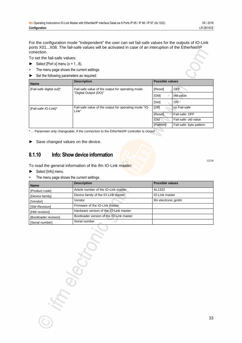
For the configuration mode "Independent" the user can set fail-safe values for the outputs of IO-Link ports X01...X08. The fail-safe values will be activated in case of an interuption of the EtherNet/IP conection.
To set the fail-safe values:
► Select [Port x] menu (x = 1...8).
> The menu page shows the current settings.
► Set the following parameters as required:
Name Description Possible values
[Fail-safe digital out]* Fail-safe value of the output for operating mode "Digital Output (DO)"
[Reset] OFF
[Old] old value
[Set] ON
[Fail-safe IO-Link]* Fail-safe value of the output for operating mode "IO-Link"
[Off] no Fail-safe
[Reset] Fail-safe: OFF
[Old Fail-safe: old value
[Pattern] Fail-safe: byte pattern
* ... Parameter only changeable, if the connection to the EtherNet/IP controller is closed
► Save changed values on the device. >
8.1.10 Info: Show device information 12218
To read the general information of the ifm IO-Link master:
► Select [Info] menu.
> The menu page shows the current settings.
Name Description Possible values
[Product code] Article number of the IO-Link master AL1322
[Device family] Device family of the IO-Link master IO-Link master
[Vendor] Vendor ifm electronic gmbh
[SW-Revision] Firmware of the IO-Link master
[HW revision] Hardware version of the IO-Link master
[Bootloader revision] Bootloader version of the IO-Link master
[Serial number] Serial number
34
ifm Operating Instructions IO-Link Master with EtherNet/IP interface DataLine 8 Ports IP 65 / IP 66 / IP 67 (AL1322) 05 / 2018
Configuration LR DEVICE
8.1.11 Firmware: Reset device to factory settings 7209
When the IO-Link master is reset, all parameters are set to the factory settings:
To reset the device to factory settings:
► Select [Firmware] menu.
> The menu page shows the current settings.
► Click on [Factory Reset] to reset the device.
> LR DEVICE sets the device to the factory settings. >
8.1.12 Firmware: Reboot the device 18105
When rebooting the device, all settings are kept.
To restart the AL1322:
► Select [Firmware] menu.
> The menu page shows the current settings.
► Click on [Reboot] to reboot the device.
> LR DEVICE reboots the ifm IO-Link master.
35
ifm Operating Instructions IO-Link Master with EtherNet/IP interface DataLine 8 Ports IP 65 / IP 66 / IP 67 (AL1322) 05 / 2018
Configuration LR DEVICE
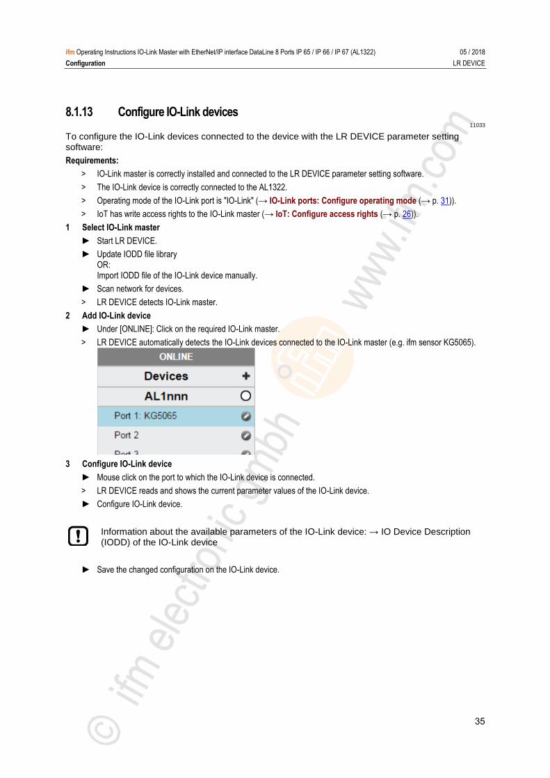
8.1.13 Configure IO-Link devices 11033
To configure the IO-Link devices connected to the device with the LR DEVICE parameter setting software:
Requirements:
> IO-Link master is correctly installed and connected to the LR DEVICE parameter setting software.
> The IO-Link device is correctly connected to the AL1322.
> Operating mode of the IO-Link port is "IO-Link" (→ IO-Link ports: Configure operating mode (→ p. 31)).
> IoT has write access rights to the IO-Link master (→ IoT: Configure access rights (→ p. 26)).
1 Select IO-Link master
► Start LR DEVICE.
► Update IODD file library OR: Import IODD file of the IO-Link device manually.
► Scan network for devices.
> LR DEVICE detects IO-Link master.
2 Add IO-Link device
► Under [ONLINE]: Click on the required IO-Link master.
> LR DEVICE automatically detects the IO-Link devices connected to the IO-Link master (e.g. ifm sensor KG5065).
3 Configure IO-Link device
► Mouse click on the port to which the IO-Link device is connected.
> LR DEVICE reads and shows the current parameter values of the IO-Link device.
► Configure IO-Link device.
Information about the available parameters of the IO-Link device: → IO Device Description (IODD) of the IO-Link device
► Save the changed configuration on the IO-Link device.
36
ifm Operating Instructions IO-Link Master with EtherNet/IP interface DataLine 8 Ports IP 65 / IP 66 / IP 67 (AL1322) 05 / 2018
Configuration IoT Core
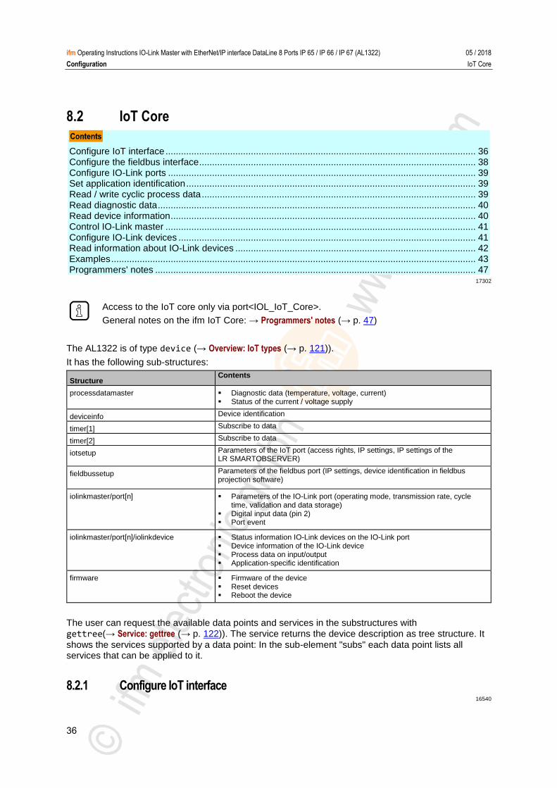
8.2 IoT Core
Configure IoT interface ........................................................................................................................ 36 Configure the fieldbus interface ........................................................................................................... 38 Configure IO-Link ports ....................................................................................................................... 39 Set application identification ................................................................................................................ 39 Read / write cyclic process data .......................................................................................................... 39 Read diagnostic data ........................................................................................................................... 40 Read device information ...................................................................................................................... 40 Control IO-Link master ........................................................................................................................ 41 Configure IO-Link devices ................................................................................................................... 41 Read information about IO-Link devices ............................................................................................. 42 Examples ............................................................................................................................................. 43 Programmers' notes ............................................................................................................................ 47
17302
Access to the IoT core only via port<IOL_IoT_Core>.
General notes on the ifm IoT Core: → Programmers' notes (→ p. 47)
The AL1322 is of type device (→ Overview: IoT types (→ p. 121)).
It has the following sub-structures:
Structure Contents
processdatamaster Diagnostic data (temperature, voltage, current) Status of the current / voltage supply
deviceinfo Device identification
timer[1] Subscribe to data
timer[2] Subscribe to data
iotsetup Parameters of the IoT port (access rights, IP settings, IP settings of the LR SMARTOBSERVER)
fieldbussetup Parameters of the fieldbus port (IP settings, device identification in fieldbus projection software)
iolinkmaster/port[n] Parameters of the IO-Link port (operating mode, transmission rate, cycletime, validation and data storage)
Digital input data (pin 2) Port event
iolinkmaster/port[n]/iolinkdevice Status information IO-Link devices on the IO-Link port Device information of the IO-Link device Process data on input/output Application-specific identification
firmware Firmware of the device Reset devices Reboot the device
The user can request the available data points and services in the substructures with gettree(→ Service: gettree (→ p. 122)). The service returns the device description as tree structure. It
shows the services supported by a data point: In the sub-element "subs" each data point lists all services that can be applied to it. >
8.2.1 Configure IoT interface 16540
37
ifm Operating Instructions IO-Link Master with EtherNet/IP interface DataLine 8 Ports IP 65 / IP 66 / IP 67 (AL1322) 05 / 2018
Configuration IoT Core
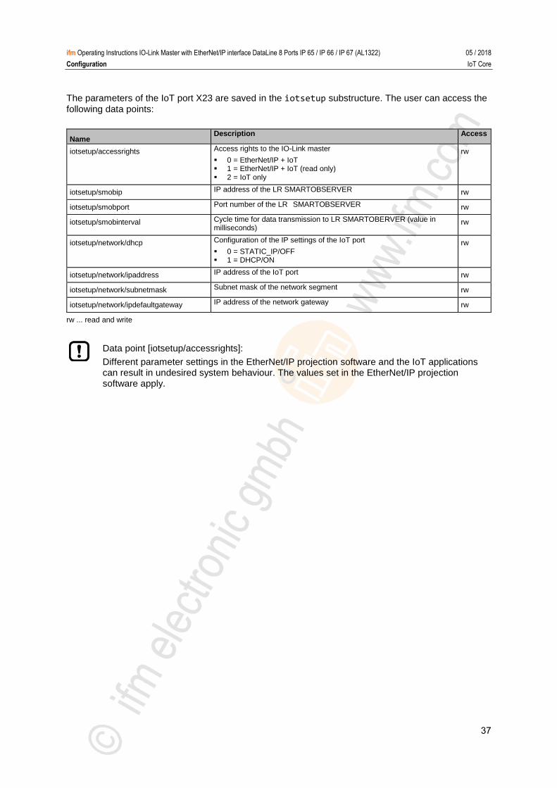
The parameters of the IoT port X23 are saved in the iotsetup substructure. The user can access the
following data points:
Name Description Access
iotsetup/accessrights Access rights to the IO-Link master
0 = EtherNet/IP + IoT 1 = EtherNet/IP + IoT (read only) 2 = IoT only
rw
iotsetup/smobip IP address of the LR SMARTOBSERVER rw
iotsetup/smobport Port number of the LR SMARTOBSERVER rw
iotsetup/smobinterval Cycle time for data transmission to LR SMARTOBERVER (value in milliseconds)
rw
iotsetup/network/dhcp Configuration of the IP settings of the IoT port
0 = STATIC_IP/OFF 1 = DHCP/ON
rw
iotsetup/network/ipaddress IP address of the IoT port rw
iotsetup/network/subnetmask Subnet mask of the network segment rw
iotsetup/network/ipdefaultgateway IP address of the network gateway rw
rw ... read and write
Data point [iotsetup/accessrights]:
Different parameter settings in the EtherNet/IP projection software and the IoT applications can result in undesired system behaviour. The values set in the EtherNet/IP projection software apply.
38
ifm Operating Instructions IO-Link Master with EtherNet/IP interface DataLine 8 Ports IP 65 / IP 66 / IP 67 (AL1322) 05 / 2018
Configuration IoT Core
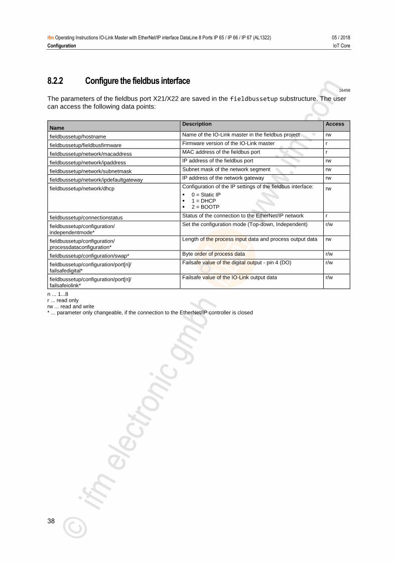
8.2.2 Configure the fieldbus interface 16458
The parameters of the fieldbus port X21/X22 are saved in the fieldbussetup substructure. The user
can access the following data points:
Name Description Access
fieldbussetup/hostname Name of the IO-Link master in the fieldbus project rw
fieldbussetup/fieldbusfirmware Firmware version of the IO-Link master r
fieldbussetup/network/macaddress MAC address of the fieldbus port r
fieldbussetup/network/ipaddress IP address of the fieldbus port rw
fieldbussetup/network/subnetmask Subnet mask of the network segment rw
fieldbussetup/network/ipdefaultgateway IP address of the network gateway rw
fieldbussetup/network/dhcp Configuration of the IP settings of the fieldbus interface:
0 = Static IP 1 = DHCP 2 = BOOTP
rw
fieldbussetup/connectionstatus Status of the connection to the EtherNet/IP network r
fieldbussetup/configuration/ independentmode*
Set the configuration mode (Top-down, Independent) r/w
fieldbussetup/configuration/ processdataconfiguration*
Length of the process input data and process output data rw
fieldbussetup/configuration/swap* Byte order of process data r/w
fieldbussetup/configuration/port[n]/ failsafedigital*
Failsafe value of the digital output - pin 4 (DO) r/w
fieldbussetup/configuration/port[n]/ failsafeiolink*
Failsafe value of the IO-Link output data r/w
n ... 1...8 r ... read only rw ... read and write * ... parameter only changeable, if the connection to the EtherNet/IP controller is closed
39
ifm Operating Instructions IO-Link Master with EtherNet/IP interface DataLine 8 Ports IP 65 / IP 66 / IP 67 (AL1322) 05 / 2018
Configuration IoT Core
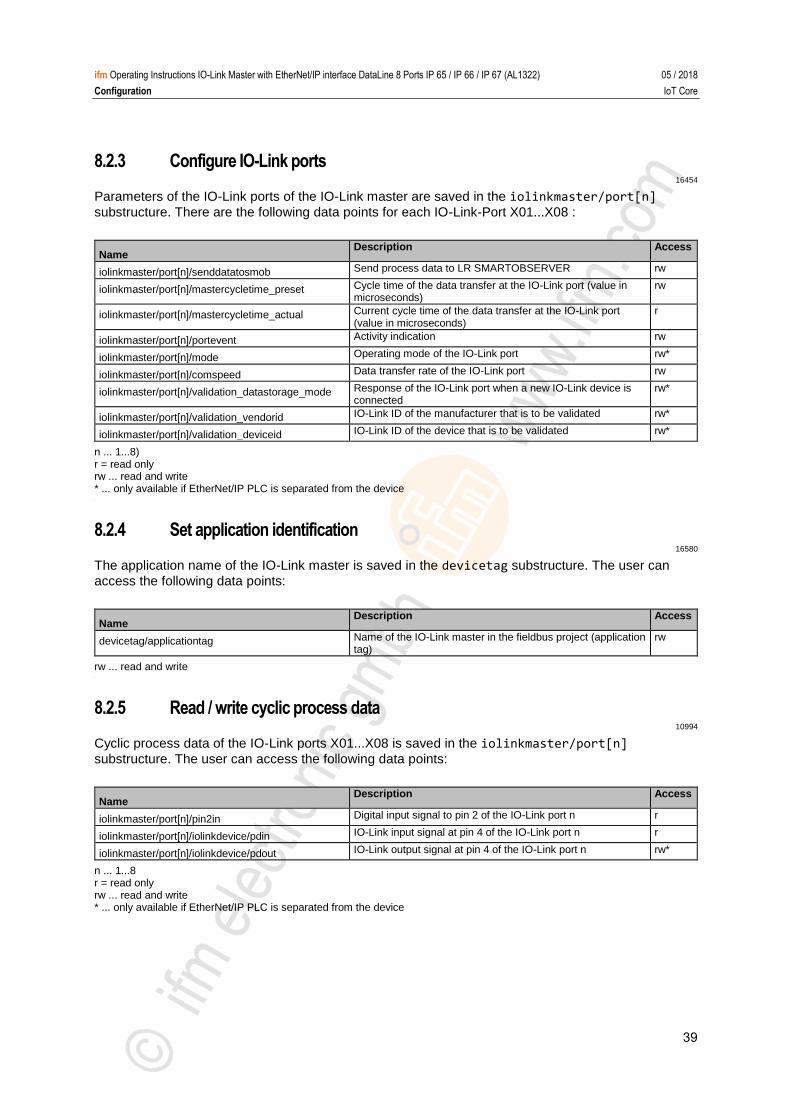
8.2.3 Configure IO-Link ports 16454
Parameters of the IO-Link ports of the IO-Link master are saved in the iolinkmaster/port[n]
substructure. There are the following data points for each IO-Link-Port X01...X08 :
Name Description Access
iolinkmaster/port[n]/senddatatosmob Send process data to LR SMARTOBSERVER rw
iolinkmaster/port[n]/mastercycletime_preset Cycle time of the data transfer at the IO-Link port (value in microseconds)
rw
iolinkmaster/port[n]/mastercycletime_actual Current cycle time of the data transfer at the IO-Link port (value in microseconds)
r
iolinkmaster/port[n]/portevent Activity indication rw
iolinkmaster/port[n]/mode Operating mode of the IO-Link port rw*
iolinkmaster/port[n]/comspeed Data transfer rate of the IO-Link port rw
iolinkmaster/port[n]/validation_datastorage_mode Response of the IO-Link port when a new IO-Link device is connected
rw*
iolinkmaster/port[n]/validation_vendorid IO-Link ID of the manufacturer that is to be validated rw*
iolinkmaster/port[n]/validation_deviceid IO-Link ID of the device that is to be validated rw*
n ... 1...8) r = read only rw ... read and write * ... only available if EtherNet/IP PLC is separated from the device >
8.2.4 Set application identification 16580
The application name of the IO-Link master is saved in the devicetag substructure. The user can
access the following data points:
Name Description Access
devicetag/applicationtag Name of the IO-Link master in the fieldbus project (application tag)
rw
rw ... read and write >
8.2.5 Read / write cyclic process data 10994
Cyclic process data of the IO-Link ports X01...X08 is saved in the iolinkmaster/port[n]
substructure. The user can access the following data points:
Name Description Access
iolinkmaster/port[n]/pin2in Digital input signal to pin 2 of the IO-Link port n r
iolinkmaster/port[n]/iolinkdevice/pdin IO-Link input signal at pin 4 of the IO-Link port n r
iolinkmaster/port[n]/iolinkdevice/pdout IO-Link output signal at pin 4 of the IO-Link port n rw*
n ... 1...8 r = read only rw ... read and write * ... only available if EtherNet/IP PLC is separated from the device
40
ifm Operating Instructions IO-Link Master with EtherNet/IP interface DataLine 8 Ports IP 65 / IP 66 / IP 67 (AL1322) 05 / 2018
Configuration IoT Core
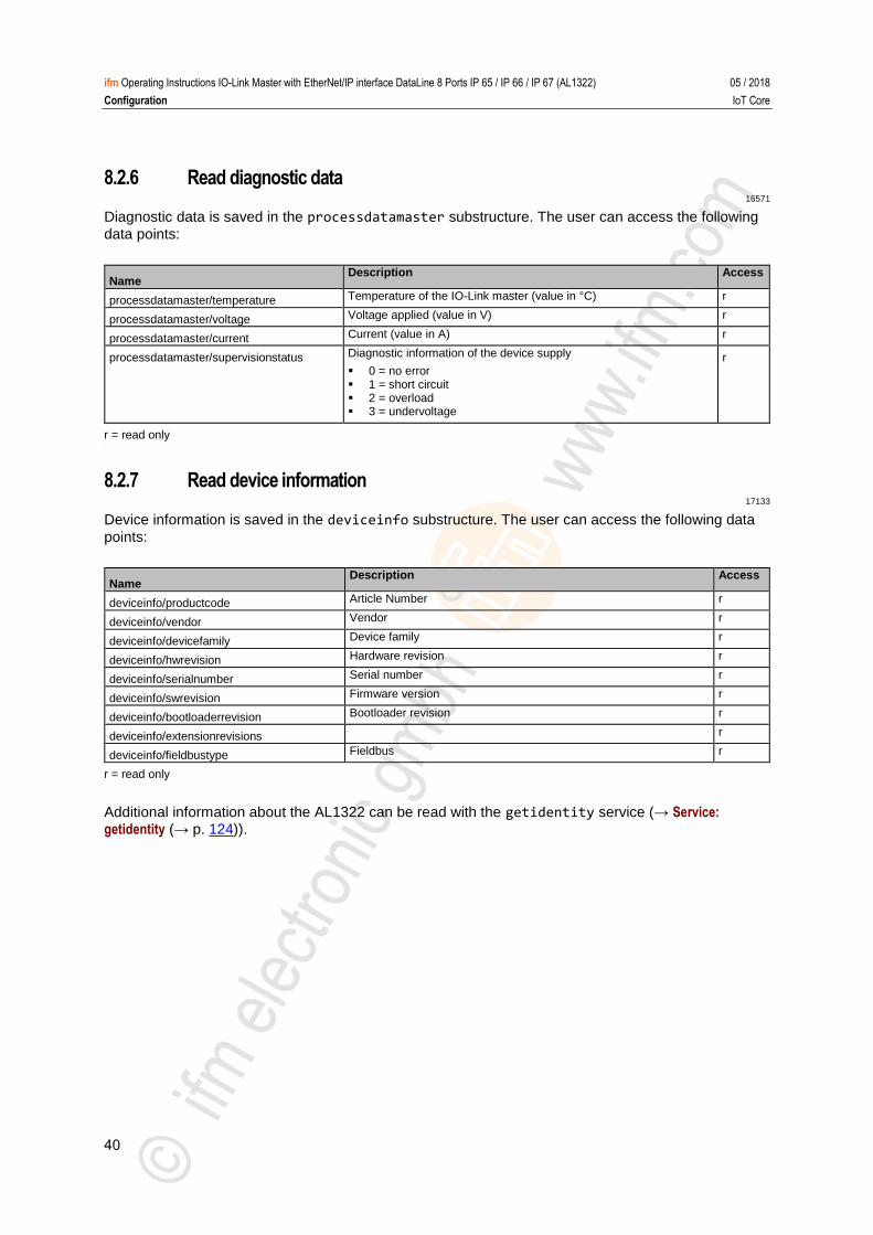
8.2.6 Read diagnostic data 16571
Diagnostic data is saved in the processdatamaster substructure. The user can access the following
data points:
Name Description Access
processdatamaster/temperature Temperature of the IO-Link master (value in °C) r
processdatamaster/voltage Voltage applied (value in V) r
processdatamaster/current Current (value in A) r
processdatamaster/supervisionstatus Diagnostic information of the device supply
0 = no error 1 = short circuit 2 = overload 3 = undervoltage
r
r = read only >
8.2.7 Read device information 17133
Device information is saved in the deviceinfo substructure. The user can access the following data
points:
Name Description Access
deviceinfo/productcode Article Number r
deviceinfo/vendor Vendor r
deviceinfo/devicefamily Device family r
deviceinfo/hwrevision Hardware revision r
deviceinfo/serialnumber Serial number r
deviceinfo/swrevision Firmware version r
deviceinfo/bootloaderrevision Bootloader revision r
deviceinfo/extensionrevisions r
deviceinfo/fieldbustype Fieldbus r
r = read only
Additional information about the AL1322 can be read with the getidentity service (→ Service: getidentity (→ p. 124)).
41
ifm Operating Instructions IO-Link Master with EtherNet/IP interface DataLine 8 Ports IP 65 / IP 66 / IP 67 (AL1322) 05 / 2018
Configuration IoT Core
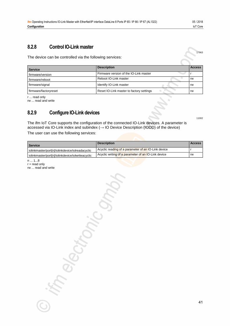
8.2.8 Control IO-Link master 17963
The device can be controlled via the following services:
Service Description Access
firmware/version Firmware version of the IO-Link master r
firmware/reboot Reboot IO-Link master rw
firmware/signal Identify IO-Link master rw
firmware/factoryreset Reset IO-Link master to factory settings rw
r ... read only rw ... read and write >
8.2.9 Configure IO-Link devices 11002
The ifm IoT Core supports the configuration of the connected IO-Link devices. A parameter is accessed via IO-Link index and subindex (→ IO Device Description (IODD) of the device)
The user can use the following services:
Service Description Access
iolinkmaster/port[n]/iolinkdevice/iolreadacyclic Acyclic reading of a parameter of an IO-Link device r
iolinkmaster/port[n]/iolinkdevice/iolwriteacyclic Acyclic writing of a parameter of an IO-Link device rw
n ... 1...8 r = read only rw ... read and write
42
ifm Operating Instructions IO-Link Master with EtherNet/IP interface DataLine 8 Ports IP 65 / IP 66 / IP 67 (AL1322) 05 / 2018
Configuration IoT Core
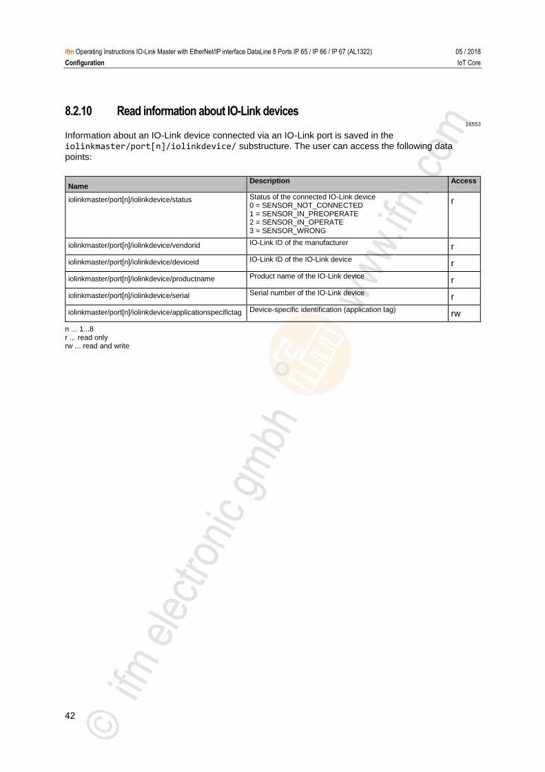
8.2.10 Read information about IO-Link devices 16553
Information about an IO-Link device connected via an IO-Link port is saved in the iolinkmaster/port[n]/iolinkdevice/ substructure. The user can access the following data
points:
Name Description Access
iolinkmaster/port[n]/iolinkdevice/status Status of the connected IO-Link device 0 = SENSOR_NOT_CONNECTED 1 = SENSOR_IN_PREOPERATE 2 = SENSOR_IN_OPERATE 3 = SENSOR_WRONG
r
iolinkmaster/port[n]/iolinkdevice/vendorid IO-Link ID of the manufacturer r
iolinkmaster/port[n]/iolinkdevice/deviceid IO-Link ID of the IO-Link device r
iolinkmaster/port[n]/iolinkdevice/productname Product name of the IO-Link device r
iolinkmaster/port[n]/iolinkdevice/serial Serial number of the IO-Link device r
iolinkmaster/port[n]/iolinkdevice/applicationspecifictag Device-specific identification (application tag) rw
n ... 1...8 r ... read only rw ... read and write
43
ifm Operating Instructions IO-Link Master with EtherNet/IP interface DataLine 8 Ports IP 65 / IP 66 / IP 67 (AL1322) 05 / 2018
Configuration IoT Core
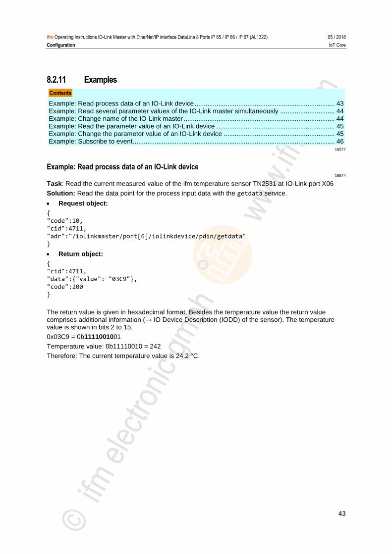
8.2.11 Examples
Example: Read process data of an IO-Link device ............................................................................. 43 Example: Read several parameter values of the IO-Link master simultaneously .............................. 44 Example: Change name of the IO-Link master ................................................................................... 44 Example: Read the parameter value of an IO-Link device ................................................................. 45 Example: Change the parameter value of an IO-Link device ............................................................. 45 Example: Subscribe to event ............................................................................................................... 46
16577 >
Example: Read process data of an IO-Link device 16574
Task: Read the current measured value of the ifm temperature sensor TN2531 at IO-Link port X06
Solution: Read the data point for the process input data with the getdata service.
Request object:
{ "code":10,
"cid":4711,
"adr":"/iolinkmaster/port[6]/iolinkdevice/pdin/getdata" }
Return object:
{
"cid":4711, "data":{"value": "03C9"},
"code":200 }
The return value is given in hexadecimal format. Besides the temperature value the return value comprises additional information (→ IO Device Description (IODD) of the sensor). The temperature value is shown in bits 2 to 15.
0x03C9 = 0b1111001001
Temperature value: 0b11110010 = 242
Therefore: The current temperature value is 24.2 °C.
44
ifm Operating Instructions IO-Link Master with EtherNet/IP interface DataLine 8 Ports IP 65 / IP 66 / IP 67 (AL1322) 05 / 2018
Configuration IoT Core
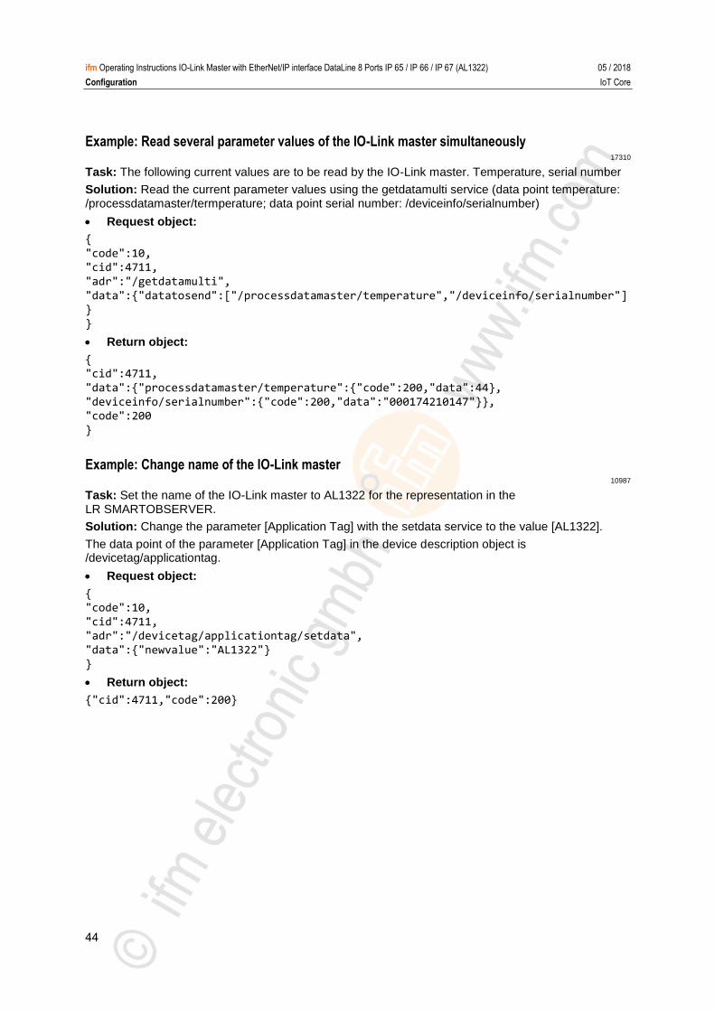
Example: Read several parameter values of the IO-Link master simultaneously 17310
Task: The following current values are to be read by the IO-Link master. Temperature, serial number
Solution: Read the current parameter values using the getdatamulti service (data point temperature: /processdatamaster/termperature; data point serial number: /deviceinfo/serialnumber)
Request object:
{
"code":10, "cid":4711,
"adr":"/getdatamulti",
"data":{"datatosend":["/processdatamaster/temperature","/deviceinfo/serialnumber"]}
}
Return object:
{ "cid":4711,
"data":{"processdatamaster/temperature":{"code":200,"data":44},
"deviceinfo/serialnumber":{"code":200,"data":"000174210147"}}, "code":200
} >
Example: Change name of the IO-Link master 10987
Task: Set the name of the IO-Link master to AL1322 for the representation in the LR SMARTOBSERVER.
Solution: Change the parameter [Application Tag] with the setdata service to the value [AL1322].
The data point of the parameter [Application Tag] in the device description object is /devicetag/applicationtag.
Request object:
{ "code":10,
"cid":4711, "adr":"/devicetag/applicationtag/setdata",
"data":{"newvalue":"AL1322"}
}
Return object:
{"cid":4711,"code":200}
45
ifm Operating Instructions IO-Link Master with EtherNet/IP interface DataLine 8 Ports IP 65 / IP 66 / IP 67 (AL1322) 05 / 2018
Configuration IoT Core
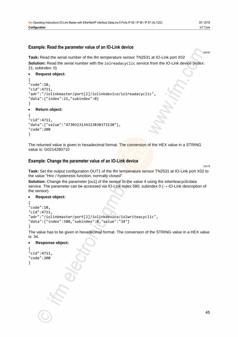
Example: Read the parameter value of an IO-Link device 16546
Task: Read the serial number of the ifm temperature sensor TN2531 at IO-Link port X02
Solution: Read the serial number with the iolreadacyclic service from the IO-Link device (index:
21, subindex: 0)
Request object:
{ "code":10,
"cid":4711, "adr":"/iolinkmaster/port[2]/iolinkdevice/iolreadacyclic",
"data":{"index":21,"subindex":0} }
Return object:
{
"cid":4711,
"data":{"value":"4730323134323830373130"}, "code":200
}
The returned value is given in hexadecimal format. The conversion of the HEX value in a STRING value is: G0214280710 >
Example: Change the parameter value of an IO-Link device 16578
Task: Set the output configuration OUT1 of the ifm temperature sensor TN2531 at IO-Link port X02 to the value "Hnc / hysteresis function, normally closed".
Solution: Change the parameter [ou1] of the sensor to the value 4 using the iolwriteacyclicdata service. The parameter can be accessed via IO-Link index 580, subindex 0 (→ IO-Link description of the sensor).
Request object:
{
"code":10, "cid":4711,
"adr":"/iolinkmaster/port[2]/iolinkdevice/iolwriteacyclic", "data":{"index":580,"subindex":0,"value":"34"}
}
The value has to be given in hexadecimal format. The conversion of the STRING value in a HEX value is: 34.
Response object:
{ "cid":4711,
"code":200 }
46
ifm Operating Instructions IO-Link Master with EtherNet/IP interface DataLine 8 Ports IP 65 / IP 66 / IP 67 (AL1322) 05 / 2018
Configuration IoT Core
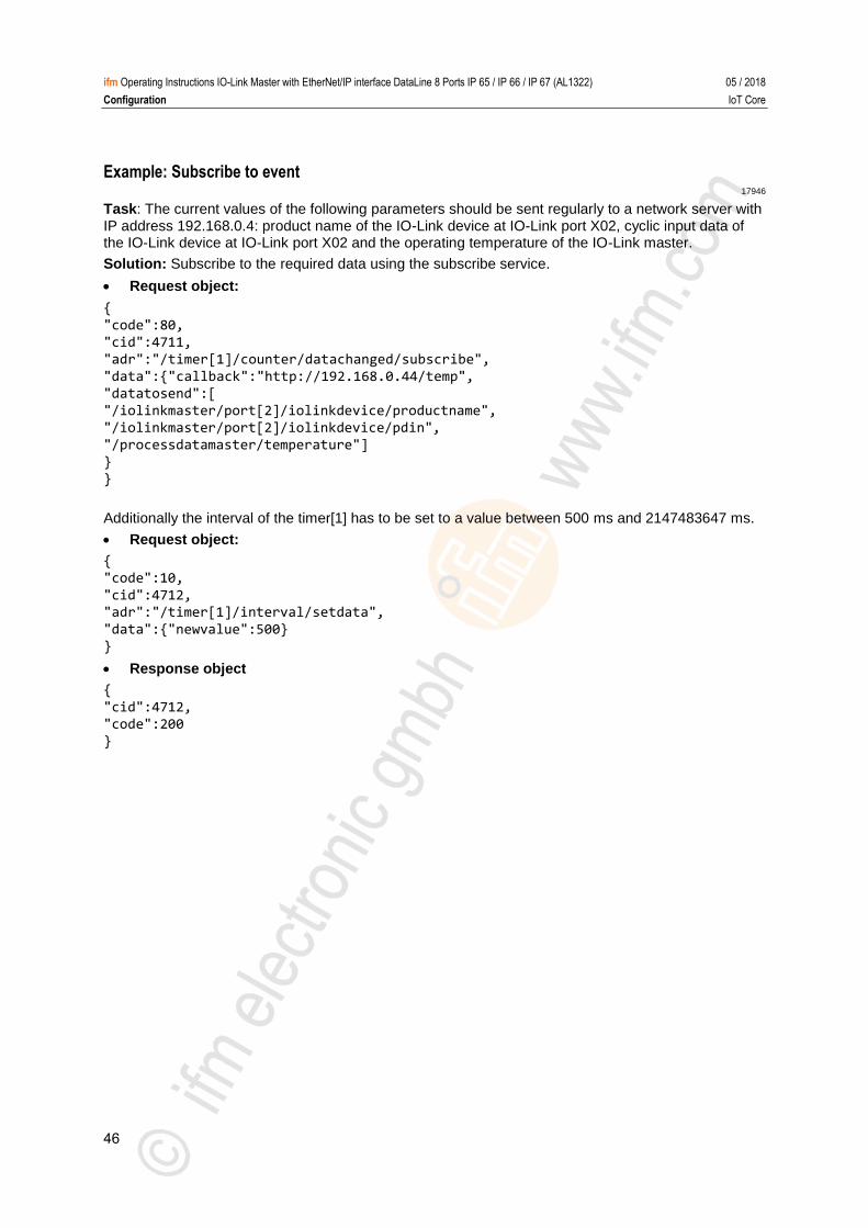
Example: Subscribe to event 17946
Task: The current values of the following parameters should be sent regularly to a network server with IP address 192.168.0.4: product name of the IO-Link device at IO-Link port X02, cyclic input data of the IO-Link device at IO-Link port X02 and the operating temperature of the IO-Link master.
Solution: Subscribe to the required data using the subscribe service.
Request object:
{
"code":80,
"cid":4711,
"adr":"/timer[1]/counter/datachanged/subscribe",
"data":{"callback":"http://192.168.0.44/temp",
"datatosend":[
"/iolinkmaster/port[2]/iolinkdevice/productname",
"/iolinkmaster/port[2]/iolinkdevice/pdin",
"/processdatamaster/temperature"]
}
}
Additionally the interval of the timer[1] has to be set to a value between 500 ms and 2147483647 ms.
Request object:
{
"code":10,
"cid":4712, "adr":"/timer[1]/interval/setdata",
"data":{"newvalue":500} }
Response object
{
"cid":4712, "code":200
}
47
ifm Operating Instructions IO-Link Master with EtherNet/IP interface DataLine 8 Ports IP 65 / IP 66 / IP 67 (AL1322) 05 / 2018
Configuration IoT Core
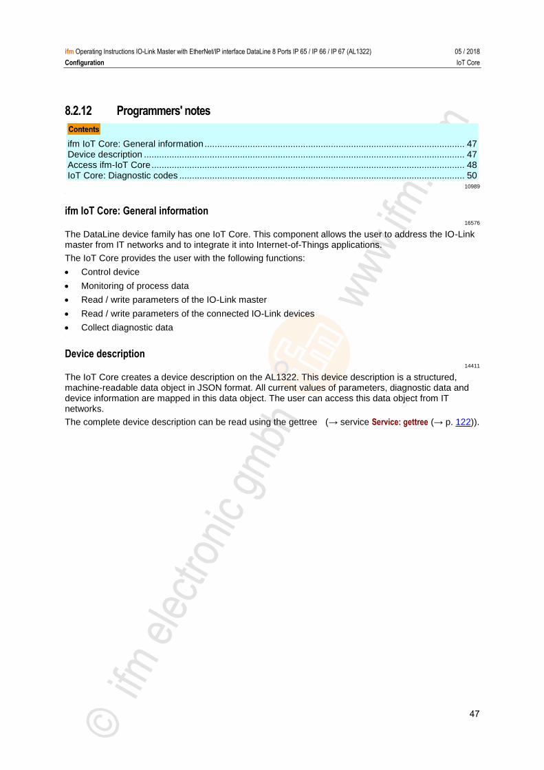
8.2.12 Programmers' notes
ifm IoT Core: General information ....................................................................................................... 47 Device description ............................................................................................................................... 47 Access ifm-IoT Core ............................................................................................................................ 48 IoT Core: Diagnostic codes ................................................................................................................. 50
10989 >
ifm IoT Core: General information 16576
The DataLine device family has one IoT Core. This component allows the user to address the IO-Link master from IT networks and to integrate it into Internet-of-Things applications.
The IoT Core provides the user with the following functions:
Control device
Monitoring of process data
Read / write parameters of the IO-Link master
Read / write parameters of the connected IO-Link devices
Collect diagnostic data >
Device description 14411
The IoT Core creates a device description on the AL1322. This device description is a structured, machine-readable data object in JSON format. All current values of parameters, diagnostic data and device information are mapped in this data object. The user can access this data object from IT networks.
The complete device description can be read using the gettree (→ service Service: gettree (→ p. 122)).
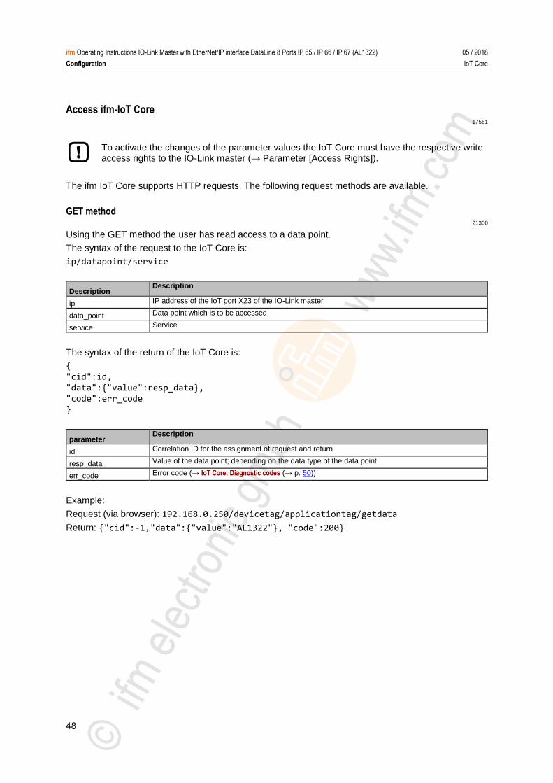
48
ifm Operating Instructions IO-Link Master with EtherNet/IP interface DataLine 8 Ports IP 65 / IP 66 / IP 67 (AL1322) 05 / 2018
Configuration IoT Core
Access ifm-IoT Core 17561
To activate the changes of the parameter values the IoT Core must have the respective write access rights to the IO-Link master (→ Parameter [Access Rights]).
The ifm IoT Core supports HTTP requests. The following request methods are available. >
GET method 21300
Using the GET method the user has read access to a data point.
The syntax of the request to the IoT Core is:
ip/datapoint/service
Description Description
ip IP address of the IoT port X23 of the IO-Link master
data_point Data point which is to be accessed
service Service
The syntax of the return of the IoT Core is:
{
"cid":id,
"data":{"value":resp_data}, "code":err_code
}
parameter Description
id Correlation ID for the assignment of request and return
resp_data Value of the data point; depending on the data type of the data point
err_code Error code (→ IoT Core: Diagnostic codes (→ p. 50))
Example:
Request (via browser): 192.168.0.250/devicetag/applicationtag/getdata
Return: {"cid":-1,"data":{"value":"AL1322"}, "code":200}
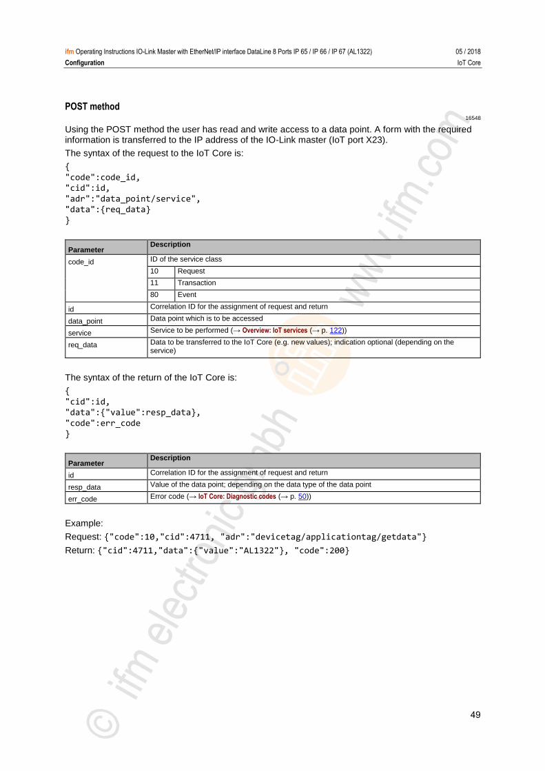
49
ifm Operating Instructions IO-Link Master with EtherNet/IP interface DataLine 8 Ports IP 65 / IP 66 / IP 67 (AL1322) 05 / 2018
Configuration IoT Core
POST method 16548
Using the POST method the user has read and write access to a data point. A form with the required information is transferred to the IP address of the IO-Link master (IoT port X23).
The syntax of the request to the IoT Core is:
{
"code":code_id, "cid":id,
"adr":"data_point/service", "data":{req_data}
}
Parameter Description
code_id ID of the service class
10 Request
11 Transaction
80 Event
id Correlation ID for the assignment of request and return
data_point Data point which is to be accessed
service Service to be performed (→ Overview: IoT services (→ p. 122))
req_data Data to be transferred to the IoT Core (e.g. new values); indication optional (depending on the service)
The syntax of the return of the IoT Core is:
{
"cid":id, "data":{"value":resp_data},
"code":err_code }
Parameter Description
id Correlation ID for the assignment of request and return
resp_data Value of the data point; depending on the data type of the data point
err_code Error code (→ IoT Core: Diagnostic codes (→ p. 50))
Example:
Request: {"code":10,"cid":4711, "adr":"devicetag/applicationtag/getdata"}
Return: {"cid":4711,"data":{"value":"AL1322"}, "code":200}
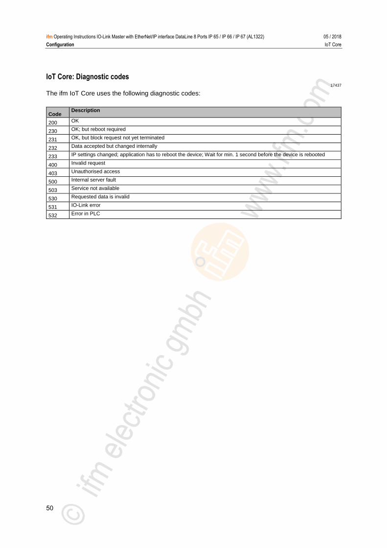
50
ifm Operating Instructions IO-Link Master with EtherNet/IP interface DataLine 8 Ports IP 65 / IP 66 / IP 67 (AL1322) 05 / 2018
Configuration IoT Core
IoT Core: Diagnostic codes 17437
The ifm IoT Core uses the following diagnostic codes:
Code Description
200 OK
230 OK; but reboot required
231 OK, but block request not yet terminated
232 Data accepted but changed internally
233 IP settings changed; application has to reboot the device; Wait for min. 1 second before the device is rebooted
400 Invalid request
403 Unauthorised access
500 Internal server fault
503 Service not available
530 Requested data is invalid
531 IO-Link error
532 Error in PLC
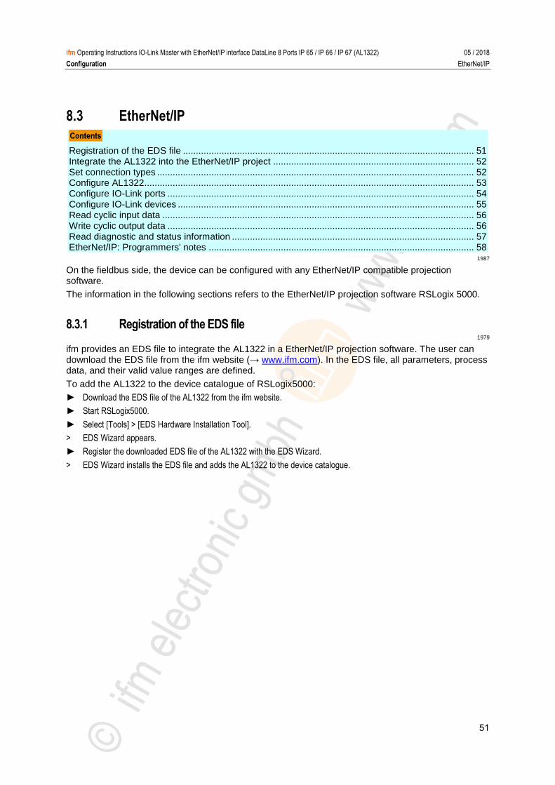
51
ifm Operating Instructions IO-Link Master with EtherNet/IP interface DataLine 8 Ports IP 65 / IP 66 / IP 67 (AL1322) 05 / 2018
Configuration EtherNet/IP
8.3 EtherNet/IP
Registration of the EDS file ................................................................................................................. 51 Integrate the AL1322 into the EtherNet/IP project .............................................................................. 52 Set connection types ........................................................................................................................... 52 Configure AL1322................................................................................................................................ 53 Configure IO-Link ports ....................................................................................................................... 54 Configure IO-Link devices ................................................................................................................... 55 Read cyclic input data ......................................................................................................................... 56 Write cyclic output data ....................................................................................................................... 56 Read diagnostic and status information .............................................................................................. 57 EtherNet/IP: Programmers' notes ....................................................................................................... 58
1987
On the fieldbus side, the device can be configured with any EtherNet/IP compatible projection software.
The information in the following sections refers to the EtherNet/IP projection software RSLogix 5000. >
8.3.1 Registration of the EDS file 1979
ifm provides an EDS file to integrate the AL1322 in a EtherNet/IP projection software. The user can download the EDS file from the ifm website (→ www.ifm.com). In the EDS file, all parameters, process data, and their valid value ranges are defined.
To add the AL1322 to the device catalogue of RSLogix5000:
► Download the EDS file of the AL1322 from the ifm website.
► Start RSLogix5000.
► Select [Tools] > [EDS Hardware Installation Tool].
> EDS Wizard appears.
► Register the downloaded EDS file of the AL1322 with the EDS Wizard.
> EDS Wizard installs the EDS file and adds the AL1322 to the device catalogue.
52
ifm Operating Instructions IO-Link Master with EtherNet/IP interface DataLine 8 Ports IP 65 / IP 66 / IP 67 (AL1322) 05 / 2018
Configuration EtherNet/IP
8.3.2 Integrate the AL1322 into the EtherNet/IP project 8015
The device is integrated as module of an I/O scanner in the EtherNet/IP project.
Requirements:
> The EDS file of the AL1322 is installed (→ Registration of the EDS file (→ p. 51)).
1 Create/open EtherNet/IP project
► Start RSLogix 5000.
► Create new EtherNet/IP project. OR Open an existing EtherNet/IP project.
2 Configure EtherNet/IP PLC and IO scanner
► Select and configure EtherNet/IP controller and IO scanner.
> EtherNet/IP project includes a EtherNet/IP controller and an IO scanner.
3 Integrate AL1322 in project
► In the Controller Organizer: Right mouse click on the IO scanner.
> Context menu appears.
► In the context menu: Select [New Module...].
> The window [Select Module Type] appears.
► Select AL1322 and click on [Create].
> The [New Module] window appears.
► Enter name and IP address of the AL1322.
► Click on [OK] to adopt the entered values.
> RSLogix 5000 adds AL1322 as sub-element of the IO scanner to the project.
4 Save the project
► Save EtherNet/IP project >
8.3.3 Set connection types 10991
The IO-Link master supports different connection types (→ Supported connection types (→ p. 72)). The user can choose which object instances of the input assembly and the output assembly are used. This makes it possible to adapt the size of the transmitted and received data.
To set the connection type:
Requirements:
> AL1322 is correctly integrated into the EtherNet/IP project (→ Integrate the AL1322 into the EtherNet/IP project (→ p. 52)).
Open the module settings
► In the Controller Organizer: Double-click on the IO-Link master node
> Dialogue window appears.
Set connection type
► Click on [Change...].
> The [Module Definition] dialogue window appears.
► Select the required connection type from the list [Connections].
► Click on [OK] to apply the changes.
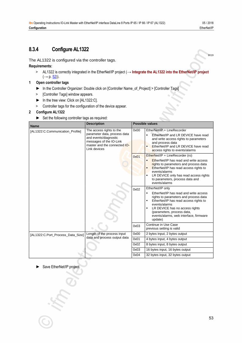
53
ifm Operating Instructions IO-Link Master with EtherNet/IP interface DataLine 8 Ports IP 65 / IP 66 / IP 67 (AL1322) 05 / 2018
Configuration EtherNet/IP
8.3.4 Configure AL1322 8019
The AL1322 is configured via the controller tags.
Requirements:
> AL1322 is correctly integrated in the EtherNet/IP project (→ Integrate the AL1322 into the EtherNet/IP project (→ p. 52)).
1 Open controller tags
► In the Controller Organizer: Double click on [Controller Name_of_Project] > [Controller Tags]
> [Controller Tags] window appears.
► In the tree view: Click on [AL1322:C].
> Controller tags for the configuration of the device appear.
2 Configure AL1322
► Set the following controller tags as required:
Name Description Possible values
[AL1322:C.Communication_Profile] The access rights to the parameter data, process data and events/diagnostic messages of the IO-Link master and the connected IO-Link devices
0x00 EtherNet/IP + LineRecorder
EtherNet/IP and LR DEVICE have read and write access rights to parameters and process data
EtherNet/IP and LR DEVICE have read access rights to events/alarms
0x01 EtherNet/IP + LineRecorder (ro)
EtherNet/IP has read and write access rights to parameters and process data
EtherNet/IP has read access rights to events/alarms
LR DEVICE only has read access rights to parameters, process data and events/alarms
0x02 EtherNet/IP only
EtherNet/IP has read and write access rights to parameters and process data
EtherNet/IP has read access rights to events/alarms
LR DEVICE has no access rights (parameters, process data, events/alarms, web interface, firmware update)
0x03 Continue in Use Case previous setting is valid
[AL1322:C.Port_Process_Data_Size] Length of the process input data and process output data
0x00 2 bytes input, 2 bytes output
0x01 4 bytes input, 4 bytes output
0x02 8 bytes input, 8 bytes output
0x03 16 bytes input, 16 bytes output
0x04 32 bytes input, 32 bytes output
► Save EtherNet/IP project
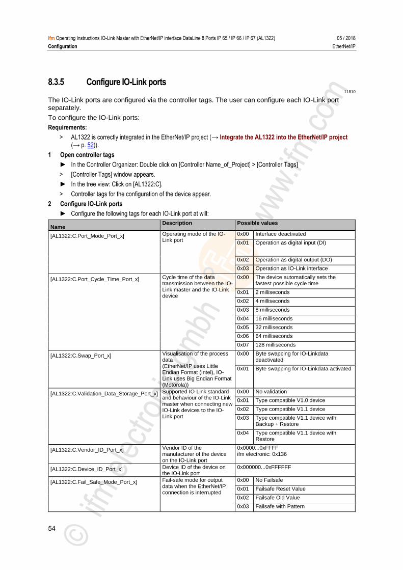
54
ifm Operating Instructions IO-Link Master with EtherNet/IP interface DataLine 8 Ports IP 65 / IP 66 / IP 67 (AL1322) 05 / 2018
Configuration EtherNet/IP
8.3.5 Configure IO-Link ports 11810
The IO-Link ports are configured via the controller tags. The user can configure each IO-Link port separately.
To configure the IO-Link ports:
Requirements:
> AL1322 is correctly integrated in the EtherNet/IP project (→ Integrate the AL1322 into the EtherNet/IP project (→ p. 52)).
1 Open controller tags
► In the Controller Organizer: Double click on [Controller Name_of_Project] > [Controller Tags]
> [Controller Tags] window appears.
► In the tree view: Click on [AL1322:C].
> Controller tags for the configuration of the device appear.
2 Configure IO-Link ports
► Configure the following tags for each IO-Link port at will:
Name Description Possible values
[AL1322:C.Port_Mode_Port_x] Operating mode of the IO-Link port
0x00 Interface deactivated
0x01 Operation as digital input (DI)
0x02 Operation as digital output (DO)
0x03 Operation as IO-Link interface
[AL1322:C.Port_Cycle_Time_Port_x] Cycle time of the data transmission between the IO-Link master and the IO-Link device
0x00 The device automatically sets the fastest possible cycle time
0x01 2 milliseconds
0x02 4 milliseconds
0x03 8 milliseconds
0x04 16 milliseconds
0x05 32 milliseconds
0x06 64 milliseconds
0x07 128 milliseconds
[AL1322:C.Swap_Port_x] Visualisation of the process data (EtherNet/IP uses Little Endian Format (Intel), IO-Link uses Big Endian Format (Motorola))
0x00 Byte swapping for IO-Linkdata deactivated
0x01 Byte swapping for IO-Linkdata activated
[AL1322:C.Validation_Data_Storage_Port_x] Supported IO-Link standard and behaviour of the IO-Link master when connecting new IO-Link devices to the IO-Link port
0x00 No validation
0x01 Type compatible V1.0 device
0x02 Type compatible V1.1 device
0x03 Type compatible V1.1 device with Backup + Restore
0x04 Type compatible V1.1 device with Restore
[AL1322:C.Vendor_ID_Port_x] Vendor ID of the manufacturer of the device on the IO-Link port
0x0000...0xFFFF ifm electronic: 0x136
[AL1322:C.Device_ID_Port_x] Device ID of the device on the IO-Link port
0x000000...0xFFFFFF
[AL1322:C.Fail_Safe_Mode_Port_x] Fail-safe mode for output data when the EtherNet/IP connection is interrupted
0x00 No Failsafe
0x01 Failsafe Reset Value
0x02 Failsafe Old Value
0x03 Failsafe with Pattern
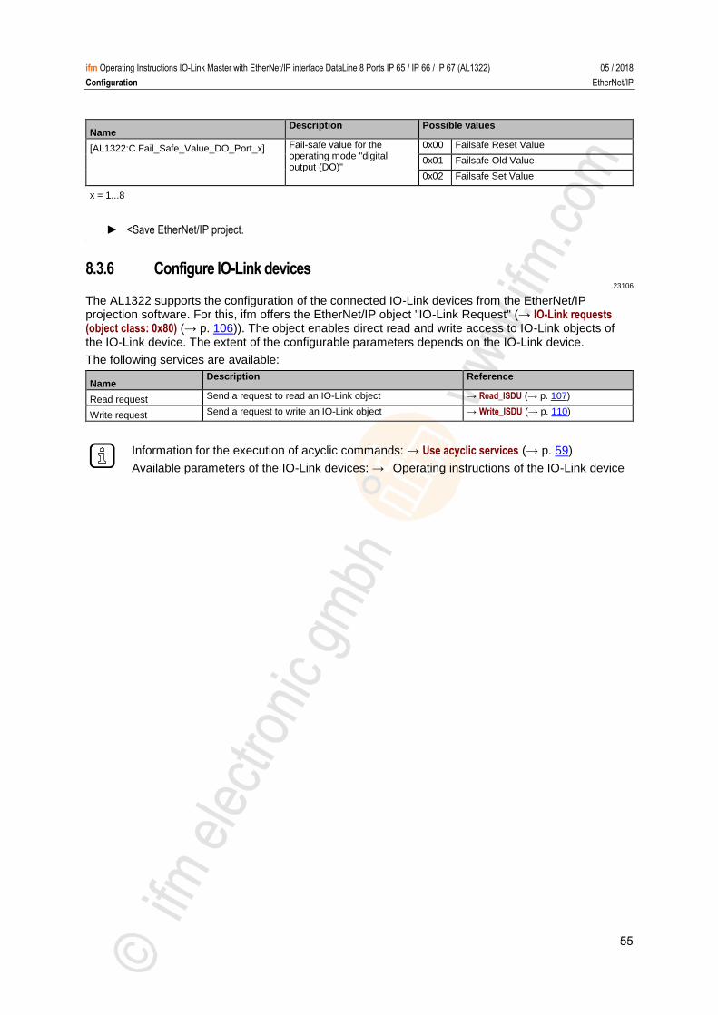
55
ifm Operating Instructions IO-Link Master with EtherNet/IP interface DataLine 8 Ports IP 65 / IP 66 / IP 67 (AL1322) 05 / 2018
Configuration EtherNet/IP
Name Description Possible values
[AL1322:C.Fail_Safe_Value_DO_Port_x] Fail-safe value for the operating mode "digital output (DO)"
0x00 Failsafe Reset Value
0x01 Failsafe Old Value
0x02 Failsafe Set Value
x = 1...8
► <Save EtherNet/IP project. >
8.3.6 Configure IO-Link devices 23106
The AL1322 supports the configuration of the connected IO-Link devices from the EtherNet/IP projection software. For this, ifm offers the EtherNet/IP object "IO-Link Request" (→ IO-Link requests (object class: 0x80) (→ p. 106)). The object enables direct read and write access to IO-Link objects of the IO-Link device. The extent of the configurable parameters depends on the IO-Link device.
The following services are available:
Name Description Reference
Read request Send a request to read an IO-Link object → Read_ISDU (→ p. 107)
Write request Send a request to write an IO-Link object → Write_ISDU (→ p. 110)
Information for the execution of acyclic commands: → Use acyclic services (→ p. 59)
Available parameters of the IO-Link devices: → Operating instructions of the IO-Link device
56
ifm Operating Instructions IO-Link Master with EtherNet/IP interface DataLine 8 Ports IP 65 / IP 66 / IP 67 (AL1322) 05 / 2018
Configuration EtherNet/IP
8.3.7 Read cyclic input data 8518
The user can access the cyclic input data of the connected sensors and IO-Link devices via the controller tags of the AL1322.
To check the validity of the cyclic process data, evaluate the PQI byte (→ Mapping: PQI (→ p. 80)).
Even with an interruption of the fieldbus connection the PQI byte indicates that the process data is valid. This can have unintended impact on the control process.
► Take suitable measures to detect an interruption of the fieldbus connection.
To access the input data:
► Starting RSLogix5000.
► Open the EtherNet/IP project.
► In the project tree: Mouse click on [Controller Tags] > [AL1322.I]
> The window shows the data structure with cyclic input data ([AL1322.I:Data])
Mapping of the inputs to the data structure [AL1322.I:Data]: → Cyclic data (→ p. 76))
>
8.3.8 Write cyclic output data 8570
The user can access the cyclic output data of the connected actuators and IO-Link devices via the controller tags of the AL1322.
To check the validity of the cyclic process data, evaluate the PQI byte (→ Mapping: PQI (→ p. 80)).
Even with an interruption of the fieldbus connection the PQI byte indicates that the process data is valid. This can have unintended impact on the control process.
► Take suitable measures to detect an interruption of the fieldbus connection.
To access the cyclic output data:
► Starting RSLogix5000.
► Open the EtherNet/IP project.
► In the project tree: Mouse click on [Controller Tags] > [AL1322.O]
> The window shows the data structure with cyclic output data ([AL1322.O:Data])
Mapping of the outputs to the data structure [AL1322.C:O]: → Cyclic data (→ p. 76)).
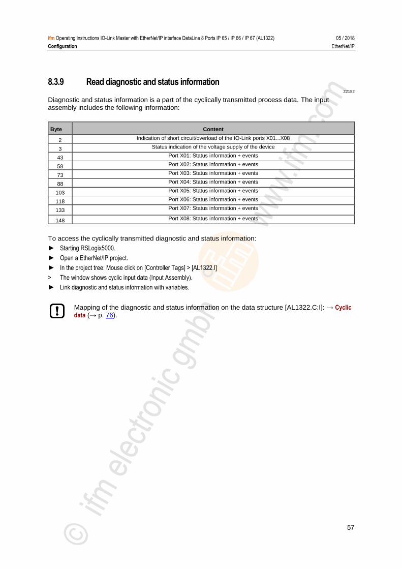
57
ifm Operating Instructions IO-Link Master with EtherNet/IP interface DataLine 8 Ports IP 65 / IP 66 / IP 67 (AL1322) 05 / 2018
Configuration EtherNet/IP
8.3.9 Read diagnostic and status information 22152
Diagnostic and status information is a part of the cyclically transmitted process data. The input assembly includes the following information:
Byte Content
2 Indication of short circuit/overload of the IO-Link ports X01...X08
3 Status indication of the voltage supply of the device
43 Port X01: Status information + events
58 Port X02: Status information + events
73 Port X03: Status information + events
88 Port X04: Status information + events
103 Port X05: Status information + events
118 Port X06: Status information + events
133 Port X07: Status information + events
148 Port X08: Status information + events
To access the cyclically transmitted diagnostic and status information:
► Starting RSLogix5000.
► Open a EtherNet/IP project.
► In the project tree: Mouse click on [Controller Tags] > [AL1322.I]
> The window shows cyclic input data (Input Assembly).
► Link diagnostic and status information with variables.
Mapping of the diagnostic and status information on the data structure [AL1322.C:I]: → Cyclic data (→ p. 76).
58
ifm Operating Instructions IO-Link Master with EtherNet/IP interface DataLine 8 Ports IP 65 / IP 66 / IP 67 (AL1322) 05 / 2018
Configuration EtherNet/IP
8.3.10 EtherNet/IP: Programmers' notes 23323
The programmer can access the following data from the PLC application:
Read cyclic input and output data of the IO-Link devices
Read diagnostic and status information
Change parameters of the IO-Link port of the AL1322
Read and change parameters of the connected IO-Link devices
The following sections show the available options. >
Supported EtherNet/IP configuration modes 8348
The AL1322 supports the following EtherNet/IP configuration modes:
Top down
Configuration of the EtherNet/IP slave with the EtherNet/IP projection software (Configuration Assembly)
EtherNet/IP plc transmitts the created configuration to the EtherNet/IP slave, where it is stored
Independent
Configuration of the EtherNet/IP slave with LR DEVICE oder IoT core
Confiuration Assembly in EtherNet/IP project is not evaluated
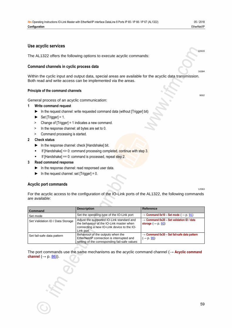
59
ifm Operating Instructions IO-Link Master with EtherNet/IP interface DataLine 8 Ports IP 65 / IP 66 / IP 67 (AL1322) 05 / 2018
Configuration EtherNet/IP
Use acyclic services 22633
The AL1322 offers the following options to execute acyclic commands: >
Command channels in cyclic process data 16384
Within the cyclic input and output data, special areas are available for the acyclic data transmission. Both read and write access can be implemented via the areas. >
Principle of the command channels 9002
General process of an acyclic communication:
1 Write command request
► In the request channel: write requested command data (without [Trigger] bit)
► Set [Trigger] = 1.
> Change of [Trigger] = 1 indicates a new command.
> In the response channel: all bytes are set to 0.
> Command processing is started.
2 Check status
► In the response channel: check [Handshake] bit.
If [Handshake] <> 0: command processing completed, continue with step 3.
If [Handshake] == 0: command is processed, repeat step 2.
3 Read command response
► In the response channel: read responsed user data.
► In the request channel: set [Trigger] = 0. >
Acyclic port commands 12063
For the acyclic access to the configuration of the IO-Link ports of the AL1322, the following commands are available:
Command Description Reference
Set mode Set the operating type of the IO-Link port → Command 0x10 – Set mode (→ p. 91)
Set Validation ID / Data Storage Adjust the supported IO-Link standard and the behaviour of the IO-Link master when connecting a new IO-Link device to the IO-Link port
→ Command 0x20 – Set validation ID / data storage (→ p. 93)
Set fail-safe data pattern Behaviour of the outputs when the EtherNet/IP connection is interrupted and setting of the corresponding fail-safe values
→ Command 0x30 – Set fail-safe data pattern (→ p. 95)
The port commands use the same mechanisms as the acyclic command channel (→ Acyclic command channel (→ p. 86)).

60
ifm Operating Instructions IO-Link Master with EtherNet/IP interface DataLine 8 Ports IP 65 / IP 66 / IP 67 (AL1322) 05 / 2018
Configuration EtherNet/IP
EtherNet/IP mechanisms for acyclic commands 7102
Acyclic commands can be executed with the EtherNet/IP command Message (MSG).
Parameters of the available field bus objects: → Field bus objects (→ p. 97)
For detailed information about the Message (MSG) command: → Operating instructions
RSLogix 5000
61
ifm Operating Instructions IO-Link Master with EtherNet/IP interface DataLine 8 Ports IP 65 / IP 66 / IP 67 (AL1322) 05 / 2018
Operation Firmware update
9 Operation
Firmware update .................................................................................................................................. 61 Web interface: Read device and diagnostic information ..................................................................... 62 Replace IO-Link device ....................................................................................................................... 63
22368 >
9.1 Firmware update 16582
The new firmware is installed via the device's web interface.
If the firmware update is not successful, deactivate all connections to the EtherNet/IP PLC, LR SMARTOBSERVER and LR DEVICE and repeat the process.
► Close connection to EtherNet/IP PLC.
► Set the parameter [IP address SmartObserver] to 255.255.255.255 or 0.0.0.0 (→ IoT:Configure the interface to the LR SMARTOBSERVER (→ p. 28)).
► Stop the LRAgent.LRDevice service in the Windows task manager.
After the firmware update check the settings of the LR SMARTOBSERVER interface!
To install a new firmware version on the device:
Requirements
> Zip file with new firmware has been downloaded and unpacked.
> Ethernet connection between laptop/PC and device is established.
1 Call up web interface
► Start web browser.
► Enter the following into the address field of the browser and press [ENTER] to confirm: http://<IP address of the device>/update
> Web browser shows the [Firmware Update] page.
2 Load new firmware to AL1322
► Click on [Search...].
> Dialogue window appears.
► Select the firmware file (.bin) and click on [Open] in order to adopt the file.
► Click on [Submit] to start the firmware update.
> Firmware is being loaded to the device.
> After successful storage, the success message is displayed.
3 Restart the device
► Click on [Restart device now] to restart the device.
> The status LED RDY flashes quickly.
> Firmware is updating.
► Follow the instructions in the browser.
62
ifm Operating Instructions IO-Link Master with EtherNet/IP interface DataLine 8 Ports IP 65 / IP 66 / IP 67 (AL1322) 05 / 2018
Operation Web interface: Read device and diagnostic information
9.2 Web interface: Read device and diagnostic information 12744
In order to read the diagnostic information about the current device status via the web interface:
► Connect laptop/PC and AL1322 via the Ethernet internet.
► Start web browser.
► Enter the IP address of the AL1322 into the address field of the browser and press [ENTER] to confirm.
> Web browser shows the web interface of the device.
> The page shows the following data:
Table with connected IO-Link devices
Name Description
[Port] Number of the IO-Link interface
[Mode] Operating mode of the IO-Link interface
[Comm. Mode] Baud rate of the IO-Link interface
[MasterCycleTime] Cycle time
[Vendor ID] ID of the manufacturer of the IO-Link device
[Device ID] ID of the IO-Link device
[Name] Article number of the IO-Link device
For ifm articles: This article number is stored along with a link to the produkt page on the ifm website.
[Serial] Serial number of the IO-Link device
[LR Mode / Interval] Cycle time for the communication with the SmartObserver
Diagnostic information of the device
Name Description
[SW-Version]
[Current] Current (in mA)
[Voltage] Voltage (in mV)
[Short Circuit] Number of detected short circuits
[Overload] Number of detected overloads
[Undervoltage] Number of detected under voltages
[Temperature] Device temperature (in °C)
Version information of the installed firmware components
Name Description
[Firmware] Firmware version
[Container] Version of the firmware container
[Bootloader Version] Version of the boot loader
[Fieldbus Firmware] Version of the EtherNet/IP firmware
63
ifm Operating Instructions IO-Link Master with EtherNet/IP interface DataLine 8 Ports IP 65 / IP 66 / IP 67 (AL1322) 05 / 2018
Operation Replace IO-Link device
9.3 Replace IO-Link device 7775
To replace an IO-Link device:
Requirement:
> IO-Link device is with factory settings.
> IO-Link device supports IO-Link standard 1.1 or higher.
1 Set data storage
► Set the following parameters of the IO-Link port: Validation and Data Storage = [Type compatible V1.1 device with Restore]
► Save changes.
2 Replace IO-Link device
► Disconnect old IO-Link device from IO-Link master.
► Connect new IO-Link device with the same IO-Link port of the AL1322.
> IO-Link master copies parameter values from the data memory to the new IO-Link device.

64
ifm Operating Instructions IO-Link Master with EtherNet/IP interface DataLine 8 Ports IP 65 / IP 66 / IP 67 (AL1322) 05 / 2018
Maintenance Replace IO-Link device
10 Maintenance 21577
The operation of the unit is maintenance-free.
► Clean the surface of the unit when necessary. Do not use any caustic cleaning agents for this!
► After use, dispose of the unit in an environmentally friendly way in accordance with the applicable national regulations.
>
65
ifm Operating Instructions IO-Link Master with EtherNet/IP interface DataLine 8 Ports IP 65 / IP 66 / IP 67 (AL1322) 05 / 2018
Factory settings Replace IO-Link device
11 Factory settings 16557
In the factory settings, the device has the following parameter settings:
parameter Factory setting
[IP address] (EtherNet/IP) 192.168.1.250
[Subnet mask] (EtherNet/IP) 255.255.255.0
[IP gateway address] (EtherNet/IP) 0.0.0.0
[IP address] (IoT-Schnittstelle) 169.254.X.X
[Subnet mask] (IoT-Schnittstelle) 255.255.0.0
[IP gateway address] (IoT-Schnittstelle) 0.0.0.0
[Host name] blank
Data memory (Data Storage) blank

66
ifm Operating Instructions IO-Link Master with EtherNet/IP interface DataLine 8 Ports IP 65 / IP 66 / IP 67 (AL1322) 05 / 2018
Accessories Replace IO-Link device
12 Accessories 17853
List of accessories of AL1322: → www.ifm.com > Product page > Accessories

67
ifm Operating Instructions IO-Link Master with EtherNet/IP interface DataLine 8 Ports IP 65 / IP 66 / IP 67 (AL1322) 05 / 2018
Appendix Replace IO-Link device
13 Appendix
Technical data ..................................................................................................................................... 68 EtherNet/IP .......................................................................................................................................... 72 ifm IoT Core ....................................................................................................................................... 117
7156
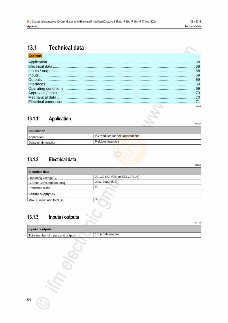
68
ifm Operating Instructions IO-Link Master with EtherNet/IP interface DataLine 8 Ports IP 65 / IP 66 / IP 67 (AL1322) 05 / 2018
Appendix Technical data
13.1 Technical data
Application ........................................................................................................................................... 68 Electrical data ...................................................................................................................................... 68 Inputs / outputs .................................................................................................................................... 68 Inputs ................................................................................................................................................... 69 Outputs ................................................................................................................................................ 69 Interfaces ............................................................................................................................................. 69 Operating conditions............................................................................................................................ 69 Approvals / tests .................................................................................................................................. 70 Mechanical data .................................................................................................................................. 70 Electrical connection............................................................................................................................ 71
9011
>
13.1.1 Application 23710
Application
Application I/O modules for field applications
Daisy-chain function Fieldbus interface
>
13.1.2 Electrical data 22819
Electrical data
Operating voltage [V] 20...30 DC; (US; to SELV/PELV)
Current Consumption [mA] 300...3900; (US)
Protection class III
Sensor supply US
Max. current load total [A] 3.6
>
13.1.3 Inputs / outputs 23711
Inputs / outputs
Total number of inputs and outputs 16; (configurable)
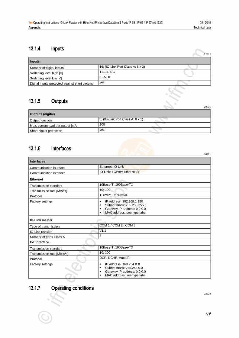
69
ifm Operating Instructions IO-Link Master with EtherNet/IP interface DataLine 8 Ports IP 65 / IP 66 / IP 67 (AL1322) 05 / 2018
Appendix Technical data
13.1.4 Inputs 22820
Inputs
Number of digital inputs 16; (IO-Link Port Class A: 8 x 2)
Switching level high [V] 11...30 DC
Switching level low [V] 0...5 DC
Digital inputs protected against short circuits yes
>
13.1.5 Outputs 22821
Outputs (digital)
Output function 8; (IO-Link Port Class A: 8 x 1)
Max. current load per output [mA] 200
Short-circuit protection yes
>
13.1.6 Interfaces 10921
Interfaces
Communication interface Ethernet; IO-Link
Communication interface IO-Link; TCP/IP; EtherNet/IP
Ethernet
Transmission standard 10Base-T; 100Base-TX
Transmission rate [MBit/s] 10; 100
Protocol TCP/IP; EtherNet/IP
Factory settings IP address: 192.168.1.250 Subnet mask: 255.255.255.0 Gateway IP address: 0.0.0.0 MAC address: see type label
IO-Link master
Type of transmission COM 1 / COM 2 / COM 3
IO-Link revision V1.1
Number of ports Class A 8
IoT interface
Transmission standard 10Base-T; 100Base-TX
Transmission rate [Mbits/s] 10; 100
Protocol DCP, DCHP, Auto IP
Factory settings IP address: 169.254.X.X Subnet mask: 255.255.0.0 Gateway IP address: 0.0.0.0 MAC address: see type label
>
13.1.7 Operating conditions 22823
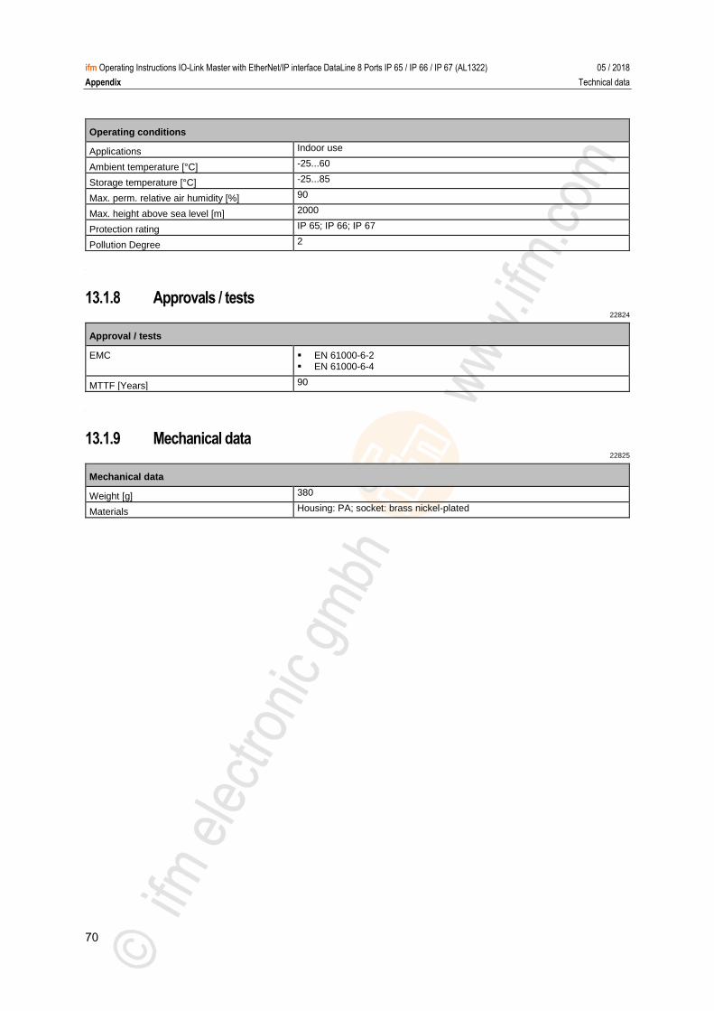
70
ifm Operating Instructions IO-Link Master with EtherNet/IP interface DataLine 8 Ports IP 65 / IP 66 / IP 67 (AL1322) 05 / 2018
Appendix Technical data
Operating conditions
Applications Indoor use
Ambient temperature [°C] -25...60
Storage temperature [°C] -25...85
Max. perm. relative air humidity [%] 90
Max. height above sea level [m] 2000
Protection rating IP 65; IP 66; IP 67
Pollution Degree 2
>
13.1.8 Approvals / tests 22824
Approval / tests
EMC EN 61000-6-2 EN 61000-6-4
MTTF [Years] 90
>
13.1.9 Mechanical data 22825
Mechanical data
Weight [g] 380
Materials Housing: PA; socket: brass nickel-plated
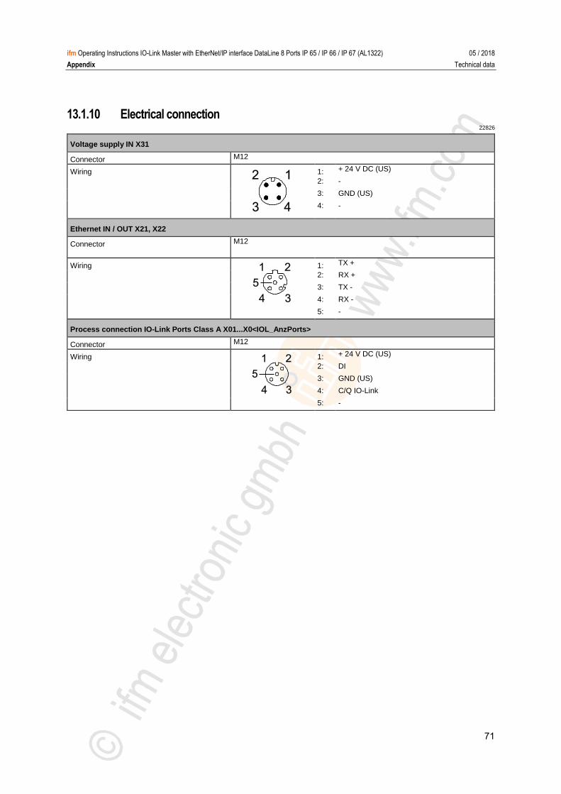
71
ifm Operating Instructions IO-Link Master with EtherNet/IP interface DataLine 8 Ports IP 65 / IP 66 / IP 67 (AL1322) 05 / 2018
Appendix Technical data
13.1.10 Electrical connection 22826
Voltage supply IN X31
Connector M12
Wiring
1: + 24 V DC (US)
2: -
3: GND (US)
4: -
Ethernet IN / OUT X21, X22
Connector M12
Wiring
1: TX +
2: RX +
3: TX -
4: RX -
5: -
Process connection IO-Link Ports Class A X01...X0<IOL_AnzPorts>
Connector M12
Wiring
1: + 24 V DC (US)
2: DI
3: GND (US)
4: C/Q IO-Link
5: -
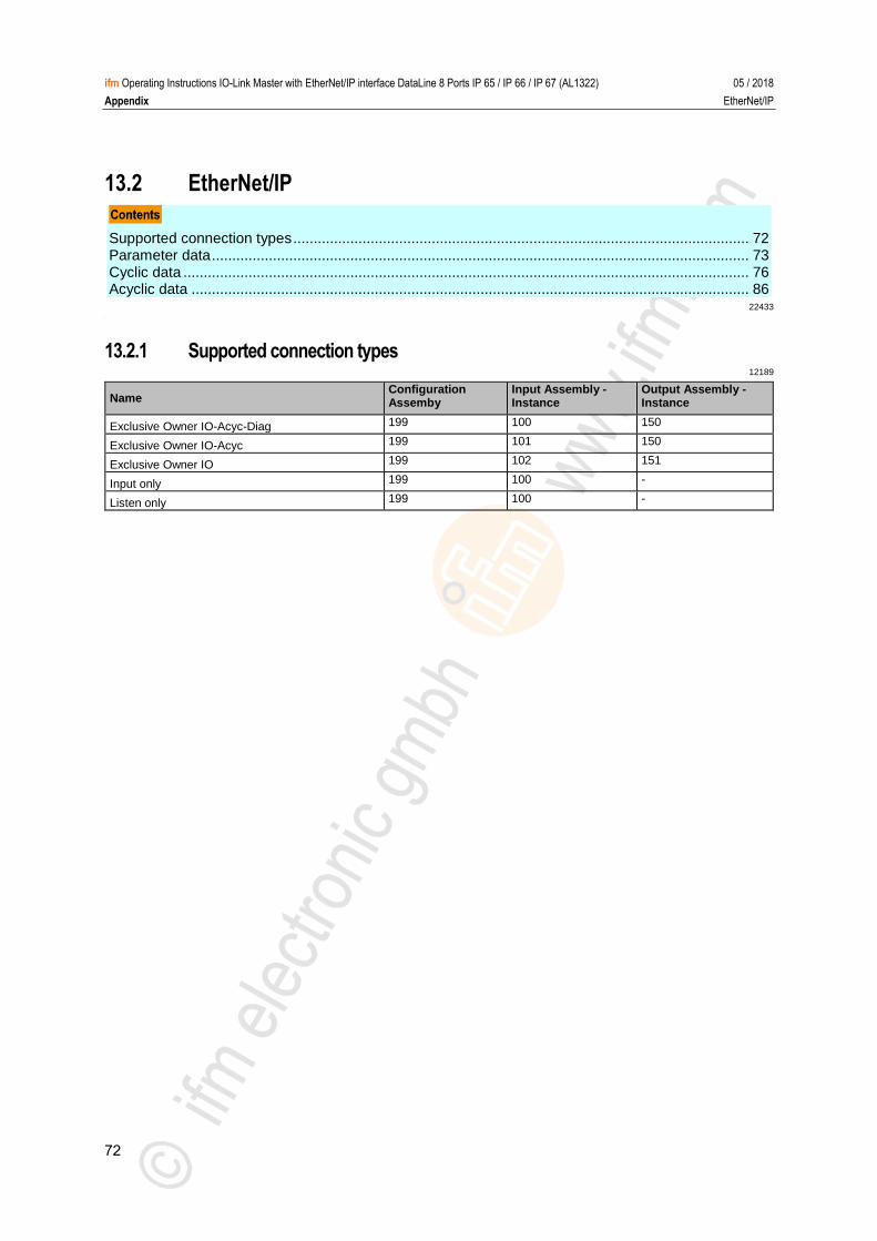
72
ifm Operating Instructions IO-Link Master with EtherNet/IP interface DataLine 8 Ports IP 65 / IP 66 / IP 67 (AL1322) 05 / 2018
Appendix EtherNet/IP
13.2 EtherNet/IP
Supported connection types ................................................................................................................ 72 Parameter data .................................................................................................................................... 73 Cyclic data ........................................................................................................................................... 76 Acyclic data ......................................................................................................................................... 86
22433 >
13.2.1 Supported connection types 12189
Name Configuration Assemby
Input Assembly - Instance
Output Assembly - Instance
Exclusive Owner IO-Acyc-Diag 199 100 150
Exclusive Owner IO-Acyc 199 101 150
Exclusive Owner IO 199 102 151
Input only 199 100 -
Listen only 199 100 -
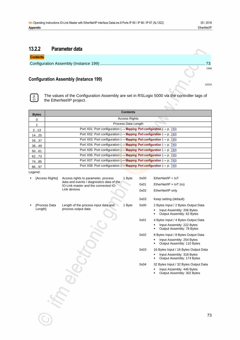
73
ifm Operating Instructions IO-Link Master with EtherNet/IP interface DataLine 8 Ports IP 65 / IP 66 / IP 67 (AL1322) 05 / 2018
Appendix EtherNet/IP
13.2.2 Parameter data
Configuration Assembly (Instance 199) .............................................................................................. 73 1568
>
Configuration Assembly (Instance 199) 10234
The values of the Configuration Assembly are set in RSLogix 5000 via the controller tags of the EtherNet/IP project.
Bytes Contents
0 Access Rights
1 Process Data Length
2...13 Port X01: Port configuration (→ Mapping: Port configuration (→ p. 74))
14...25 Port X02: Port configuration (→ Mapping: Port configuration (→ p. 74))
26...37 Port X03: Port configuration (→ Mapping: Port configuration (→ p. 74))
38...49 Port X04: Port configuration (→ Mapping: Port configuration (→ p. 74))
50...61 Port X05: Port configuration (→ Mapping: Port configuration (→ p. 74))
62...73 Port X06: Port configuration (→ Mapping: Port configuration (→ p. 74))
74...85 Port X07: Port configuration (→ Mapping: Port configuration (→ p. 74))
86...97 Port X08: Port configuration (→ Mapping: Port configuration (→ p. 74))
Legend:
[Access Rights] Access rights to parameter, process data and events / diagnostics data of the IO-Link master and the connected IO-Link devices
1 Byte 0x00 EtherNet/IP + IoT
0x01 EtherNet/IP + IoT (ro)
0x02 EtherNet/IP only
0x03 Keep setting (default)
[Process Data Length]
Length of the process input data and process output data
1 Byte 0x00 2 Bytes Input / 2 Bytes Output Data
Input Assembly: 206 Bytes Output Assembly: 62 Bytes
0x01 4 Bytes Input / 4 Bytes Output Data
Input Assembly: 222 Bytes Output Assembly: 78 Bytes
0x02 8 Bytes Input / 8 Bytes Output Data
Input Assembly: 254 Bytes Output Assembly: 110 Bytes
0x03 16 Bytes Input / 16 Bytes Output Data
Input Assembly: 318 Bytes Output Assembly: 174 Bytes
0x04 32 Bytes Input / 32 Bytes Output Data
Input Assembly: 446 Bytes Output Assembly: 302 Bytes
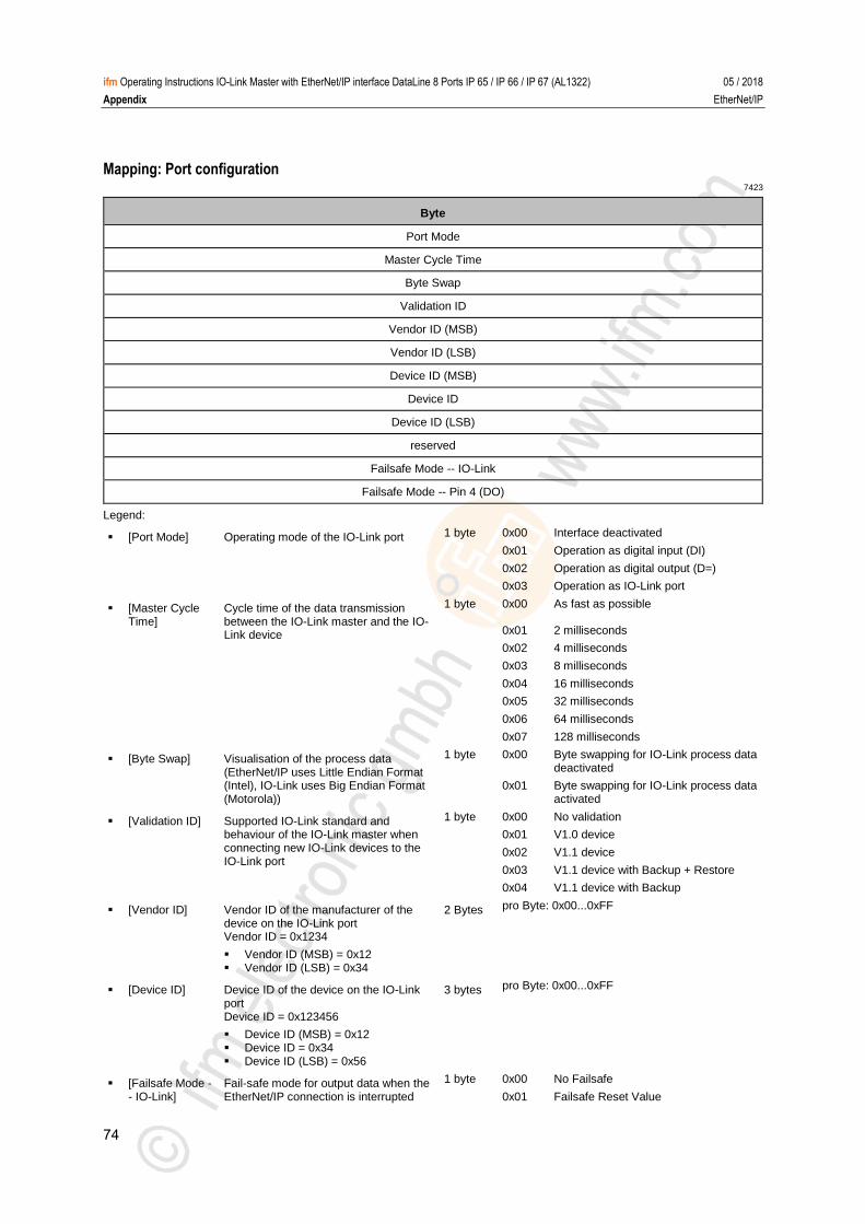
74
ifm Operating Instructions IO-Link Master with EtherNet/IP interface DataLine 8 Ports IP 65 / IP 66 / IP 67 (AL1322) 05 / 2018
Appendix EtherNet/IP
Mapping: Port configuration 7423
Byte
Port Mode
Master Cycle Time
Byte Swap
Validation ID
Vendor ID (MSB)
Vendor ID (LSB)
Device ID (MSB)
Device ID
Device ID (LSB)
reserved
Failsafe Mode -- IO-Link
Failsafe Mode -- Pin 4 (DO)
Legend:
[Port Mode] Operating mode of the IO-Link port 1 byte 0x00 Interface deactivated
0x01 Operation as digital input (DI)
0x02 Operation as digital output (D=)
0x03 Operation as IO-Link port
[Master Cycle Time]
Cycle time of the data transmission between the IO-Link master and the IO-Link device
1 byte 0x00 As fast as possible
0x01 2 milliseconds
0x02 4 milliseconds
0x03 8 milliseconds
0x04 16 milliseconds
0x05 32 milliseconds
0x06 64 milliseconds
0x07 128 milliseconds
[Byte Swap] Visualisation of the process data (EtherNet/IP uses Little Endian Format (Intel), IO-Link uses Big Endian Format (Motorola))
1 byte 0x00 Byte swapping for IO-Link process data deactivated
0x01 Byte swapping for IO-Link process data activated
[Validation ID] Supported IO-Link standard and behaviour of the IO-Link master when connecting new IO-Link devices to the IO-Link port
1 byte 0x00 No validation
0x01 V1.0 device
0x02 V1.1 device
0x03 V1.1 device with Backup + Restore
0x04 V1.1 device with Backup
[Vendor ID] Vendor ID of the manufacturer of the device on the IO-Link port Vendor ID = 0x1234
Vendor ID (MSB) = 0x12 Vendor ID (LSB) = 0x34
2 Bytes pro Byte: 0x00...0xFF
[Device ID] Device ID of the device on the IO-Link port Device ID = 0x123456
Device ID (MSB) = 0x12 Device ID = 0x34 Device ID (LSB) = 0x56
3 bytes pro Byte: 0x00...0xFF
[Failsafe Mode -- IO-Link]
Fail-safe mode for output data when the EtherNet/IP connection is interrupted
1 byte 0x00 No Failsafe
0x01 Failsafe Reset Value

75
ifm Operating Instructions IO-Link Master with EtherNet/IP interface DataLine 8 Ports IP 65 / IP 66 / IP 67 (AL1322) 05 / 2018
Appendix EtherNet/IP
0x02 Failsafe Old Value
0x03 Failsafe with Pattern
[Failsafe Mode -- Pin 4 (DO)]
Fail-safe value for the operating mode "digital output (DO)"
1 byte 0x00 Failsafe Reset Value
0x01 Failsafe Old Value
0x02 Failsafe Set Value
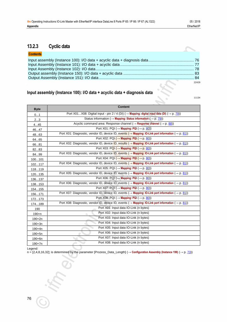
76
ifm Operating Instructions IO-Link Master with EtherNet/IP interface DataLine 8 Ports IP 65 / IP 66 / IP 67 (AL1322) 05 / 2018
Appendix EtherNet/IP
13.2.3 Cyclic data
Input assembly (Instance 100): I/O data + acyclic data + diagnosis data ........................................... 76 Input Assembly (Instance 101): I/O data + acyclic data ...................................................................... 77 Input Assembly (Instance 102): I/O data ............................................................................................. 78 Output assembly (Instance 150): I/O data + acyclic data ................................................................... 83 Output Assembly (Instance 151): I/O data .......................................................................................... 84
22429 >
Input assembly (Instance 100): I/O data + acyclic data + diagnosis data 11134
Byte Content
0...1 Port X01...X08: Digital input - pin 2 / 4 (DI) (→ Mapping: digital input data (DI) (→ p. 79))
2...3 Status information (→ Mapping: Status information (→ p. 79))
4...45 Acyclic command area: Response channel (→ Response channel (→ p. 88))
46...47 Port X01: PQI (→ Mapping: PQI (→ p. 80))
48...63 Port X01: Diagnostic, vendor ID, device ID, events (→ Mapping: IO-Link port information (→ p. 81))
64...65 Port X02: PQI (→ Mapping: PQI (→ p. 80))
66...81 Port X02: Diagnostic, vendor ID, device ID, results (→ Mapping: IO-Link port information (→ p. 81))
82...83 Port X03: PQI (→ Mapping: PQI (→ p. 80))
84...99 Port X03: Diagnostic, vendor ID, device ID, events (→ Mapping: IO-Link port information (→ p. 81))
100...101 Port X04: PQI (→ Mapping: PQI (→ p. 80))
102...117 Port X04: Diagnostic, vendor ID, device ID, events (→ Mapping: IO-Link port information (→ p. 81))
118...119 Port X05: PQI (→ Mapping: PQI (→ p. 80))
120...135 Port X05: Diagnostic, vendor ID, device ID, events (→ Mapping: IO-Link port information (→ p. 81))
136...137 Port X06: PQI (→ Mapping: PQI (→ p. 80))
138...153 Port X06: Diagnostic, vendor ID, device ID, events (→ Mapping: IO-Link port information (→ p. 81))
154...155 Port X07: PQI (→ Mapping: PQI (→ p. 80))
156...171 Port X07: Diagnostic, vendor ID, device ID, events (→ Mapping: IO-Link port information (→ p. 81))
172...173 Port X08: PQI (→ Mapping: PQI (→ p. 80))
174...189 Port X08: Diagnostic, vendor ID, device ID, events (→ Mapping: IO-Link port information (→ p. 81))
190 Port X01: Input data IO-Link (n bytes)
190+n Port X02: Input data IO-Link (n bytes)
190+2n Port X03: Input data IO-Link (n bytes)
190+3n Port X04: Input data IO-Link (n bytes)
190+4n Port X05: Input data IO-Link (n bytes)
190+5n Port X06: Input data IO-Link (n bytes)
190+6n Port X07: Input data IO-Link (n bytes)
190+7n Port X08: Input data IO-Link (n bytes)
Legend: n = [2,4,8,16,32]; is determined by the parameter [Prozess_Data_Length] (→ Configuration Assembly (Instance 199) (→ p. 73))
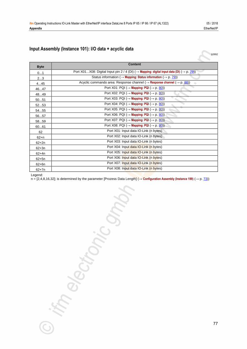
77
ifm Operating Instructions IO-Link Master with EtherNet/IP interface DataLine 8 Ports IP 65 / IP 66 / IP 67 (AL1322) 05 / 2018
Appendix EtherNet/IP
Input Assembly (Instance 101): I/O data + acyclic data 10992
Byte Content
0...1 Port X01...X08: Digital Input pin 2 / 4 (DI) (→ Mapping: digital input data (DI) (→ p. 79))
2...3 Status information (→ Mapping: Status information (→ p. 79))
4...45 Acyclic commando area: Response channel (→ Response channel (→ p. 88))
46...47 Port X01: PQI (→ Mapping: PQI (→ p. 80))
48...49 Port X02: PQI (→ Mapping: PQI (→ p. 80))
50...51 Port X03: PQI (→ Mapping: PQI (→ p. 80))
52...53 Port X04: PQI (→ Mapping: PQI (→ p. 80))
54...55 Port X05: PQI (→ Mapping: PQI (→ p. 80))
56...57 Port X06: PQI (→ Mapping: PQI (→ p. 80))
58...59 Port X07: PQI (→ Mapping: PQI (→ p. 80))
60...61 Port X08: PQI (→ Mapping: PQI (→ p. 80))
62 Port X01: Input data IO-Link (n bytes)
62+n Port X02: Input data IO-Link (n bytes)
62+2n Port X03: Input data IO-Link (n bytes)
62+3n Port X04: Input data IO-Link (n bytes)
62+4n Port X05: Input data IO-Link (n bytes)
62+5n Port X06: Input data IO-Link (n bytes)
62+6n Port X07: Input data IO-Link (n bytes)
62+7n Port X08: Input data IO-Link (n bytes)
Legend: n = [2,4,8,16,32]; is determined by the parameter [Prozess Data Length] (→ Configuration Assembly (Instance 199) (→ p. 73))
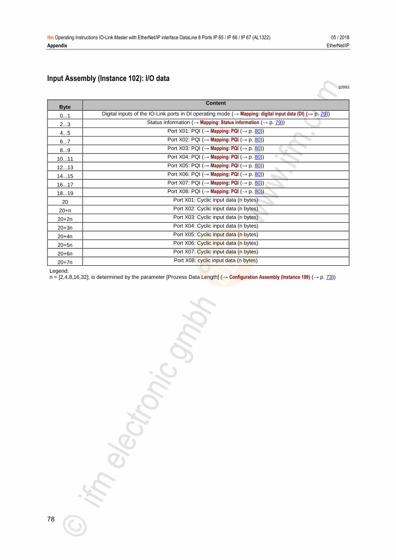
78
ifm Operating Instructions IO-Link Master with EtherNet/IP interface DataLine 8 Ports IP 65 / IP 66 / IP 67 (AL1322) 05 / 2018
Appendix EtherNet/IP
Input Assembly (Instance 102): I/O data 10993
Byte Content
0...1 Digital inputs of the IO-Link ports in DI operating mode (→ Mapping: digital input data (DI) (→ p. 79))
2...3 Status information (→ Mapping: Status information (→ p. 79))
4...5 Port X01: PQI (→ Mapping: PQI (→ p. 80))
6...7 Port X02: PQI (→ Mapping: PQI (→ p. 80))
8...9 Port X03: PQI (→ Mapping: PQI (→ p. 80))
10...11 Port X04: PQI (→ Mapping: PQI (→ p. 80))
12...13 Port X05: PQI (→ Mapping: PQI (→ p. 80))
14...15 Port X06: PQI (→ Mapping: PQI (→ p. 80))
16...17 Port X07: PQI (→ Mapping: PQI (→ p. 80))
18...19 Port X08: PQI (→ Mapping: PQI (→ p. 80))
20 Port X01: Cyclic input data (n bytes)
20+n Port X02: Cyclic input data (n bytes)
20+2n Port X03: Cyclic input data (n bytes)
20+3n Port X04: Cyclic input data (n bytes)
20+4n Port X05: Cyclic input data (n bytes)
20+5n Port X06: Cyclic input data (n bytes)
20+6n Port X07: Cyclic input data (n bytes)
20+7n Port X08: cyclic input data (n bytes)
Legend: n = [2,4,8,16,32]; is determined by the parameter [Prozess Data Length] (→ Configuration Assembly (Instance 199) (→ p. 73))
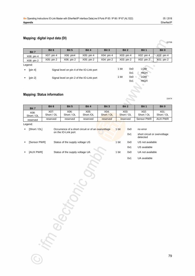
79
ifm Operating Instructions IO-Link Master with EtherNet/IP interface DataLine 8 Ports IP 65 / IP 66 / IP 67 (AL1322) 05 / 2018
Appendix EtherNet/IP
Mapping: digital input data (DI) 22708
Bit 7 Bit 6 Bit 5 Bit 4 Bit 3 Bit 2 Bit 1 Bit 0
X08: pin 4 X07: pin 4 X06: pin4 X05: pin 4 X04: pin 4 X03: pin 4 X02: pin 4 X01: pin 4
X08: pin 2 X05: pin 2 X06: pin 2 X05: pin 2 X04: pin 2 X03: pin 2 X02: pin 2 X01: pin 2
Legend:
[pin 4] Signal level on pin 4 of the IO-Link port 1 bit 0x0 LOW
0x1 HIGH
[pin 2] Signal level on pin 2 of the IO-Link port 1 bit 0x0 LOW
0x1 HIGH
>
Mapping: Status information 15474
Bit 7 Bit 6 Bit 5 Bit 4 Bit 3 Bit 2 Bit 1 Bit 0
X08: Short / OL
X07: Short / OL
X06: Short / OL
X05: Short /OL
X04: Short / OL
X03: Short / OL
X02: Short / OL
X01: Short / OL
reserved reserved reserved reserved reserved reserved Sensor PWR AUX PWR
Legend:
[Short / OL] Occurrence of a short circuit or of an overvoltage on the IO-Link port
1 bit 0x0 no error
0x1 short circuit or overvoltage detected
[Sensor PWR] Status of the supply voltage US 1 bit 0x0 US not available
0x1 US available
[AUX PWR] Status of the supply voltage UA 1 bit 0x0 UA not available
0x1 UA available
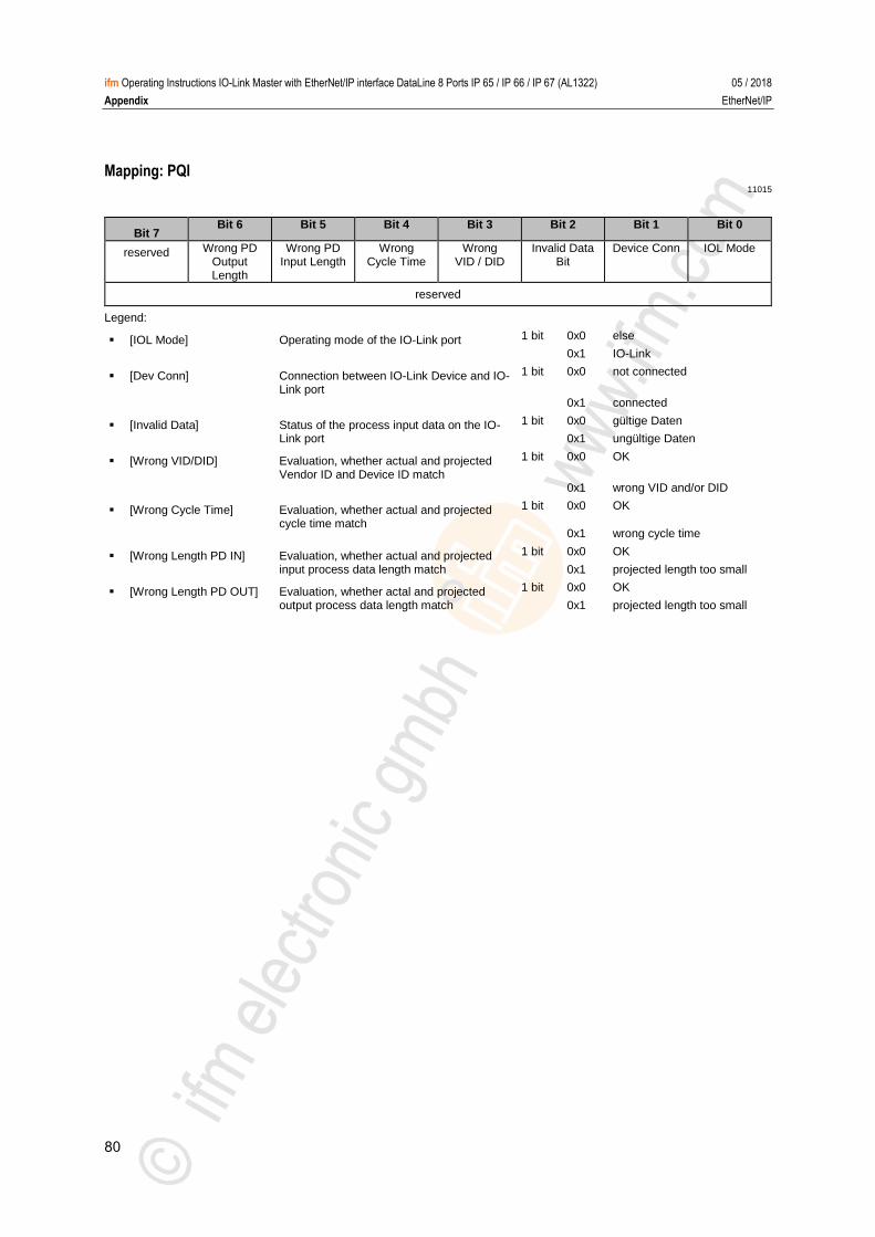
80
ifm Operating Instructions IO-Link Master with EtherNet/IP interface DataLine 8 Ports IP 65 / IP 66 / IP 67 (AL1322) 05 / 2018
Appendix EtherNet/IP
Mapping: PQI 11015
Bit 7 Bit 6 Bit 5 Bit 4 Bit 3 Bit 2 Bit 1 Bit 0
reserved Wrong PD Output Length
Wrong PD Input Length
Wrong Cycle Time
Wrong VID / DID
Invalid Data Bit
Device Conn IOL Mode
reserved
Legend:
[IOL Mode] Operating mode of the IO-Link port 1 bit 0x0 else
0x1 IO-Link
[Dev Conn] Connection between IO-Link Device and IO-Link port
1 bit 0x0 not connected
0x1 connected
[Invalid Data] Status of the process input data on the IO-Link port
1 bit 0x0 gültige Daten
0x1 ungültige Daten
[Wrong VID/DID] Evaluation, whether actual and projected Vendor ID and Device ID match
1 bit 0x0 OK
0x1 wrong VID and/or DID
[Wrong Cycle Time] Evaluation, whether actual and projected cycle time match
1 bit 0x0 OK
0x1 wrong cycle time
[Wrong Length PD IN] Evaluation, whether actual and projected input process data length match
1 bit 0x0 OK
0x1 projected length too small
[Wrong Length PD OUT] Evaluation, whether actal and projected output process data length match
1 bit 0x0 OK
0x1 projected length too small
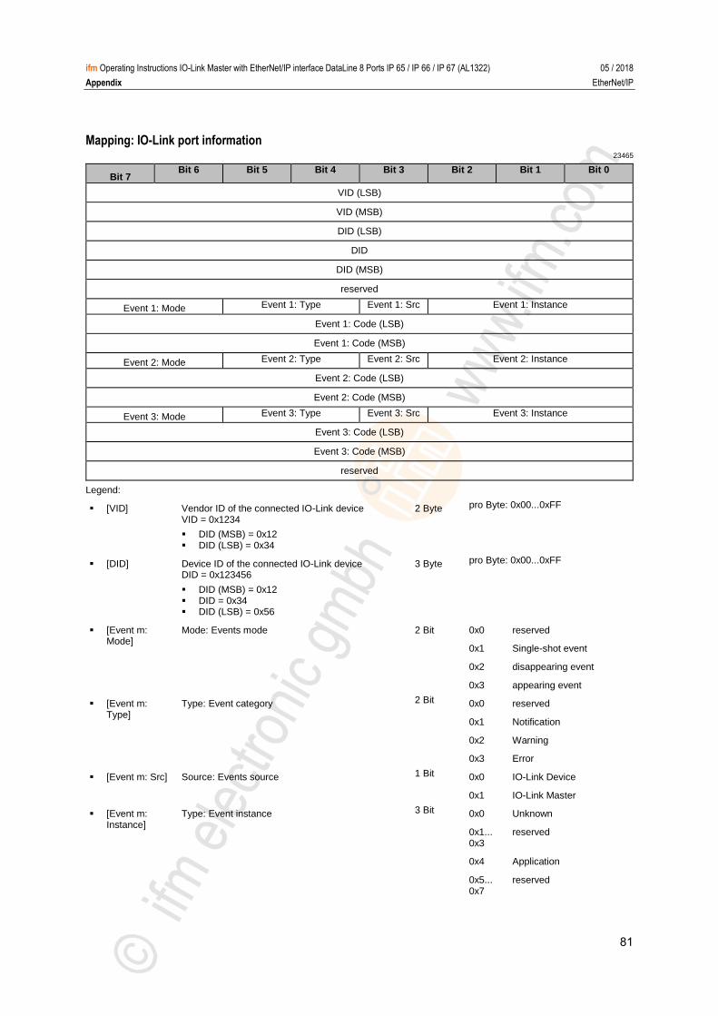
81
ifm Operating Instructions IO-Link Master with EtherNet/IP interface DataLine 8 Ports IP 65 / IP 66 / IP 67 (AL1322) 05 / 2018
Appendix EtherNet/IP
Mapping: IO-Link port information 23465
Bit 7 Bit 6 Bit 5 Bit 4 Bit 3 Bit 2 Bit 1 Bit 0
VID (LSB)
VID (MSB)
DID (LSB)
DID
DID (MSB)
reserved
Event 1: Mode Event 1: Type Event 1: Src Event 1: Instance
Event 1: Code (LSB)
Event 1: Code (MSB)
Event 2: Mode Event 2: Type Event 2: Src Event 2: Instance
Event 2: Code (LSB)
Event 2: Code (MSB)
Event 3: Mode Event 3: Type Event 3: Src Event 3: Instance
Event 3: Code (LSB)
Event 3: Code (MSB)
reserved
Legend:
[VID] Vendor ID of the connected IO-Link device VID = 0x1234
DID (MSB) = 0x12 DID (LSB) = 0x34
2 Byte pro Byte: 0x00...0xFF
[DID] Device ID of the connected IO-Link device DID = 0x123456
DID (MSB) = 0x12 DID = 0x34 DID (LSB) = 0x56
3 Byte pro Byte: 0x00...0xFF
[Event m: Mode]
Mode: Events mode 2 Bit 0x0 reserved
0x1 Single-shot event
0x2 disappearing event
0x3 appearing event
[Event m: Type]
Type: Event category 2 Bit 0x0 reserved
0x1 Notification
0x2 Warning
0x3 Error
[Event m: Src] Source: Events source 1 Bit 0x0 IO-Link Device
0x1 IO-Link Master
[Event m: Instance]
Type: Event instance 3 Bit 0x0 Unknown
0x1... 0x3
reserved
0x4 Application
0x5... 0x7
reserved

82
ifm Operating Instructions IO-Link Master with EtherNet/IP interface DataLine 8 Ports IP 65 / IP 66 / IP 67 (AL1322) 05 / 2018
Appendix EtherNet/IP
[Event m: Code]
Code: Event code; device-dependent Code = 0x1234
Code (MSB) = 0x12 Code (LSB) = 0x34
2 Byte depends on device (→ IODD instructionsof the IO-Link device)
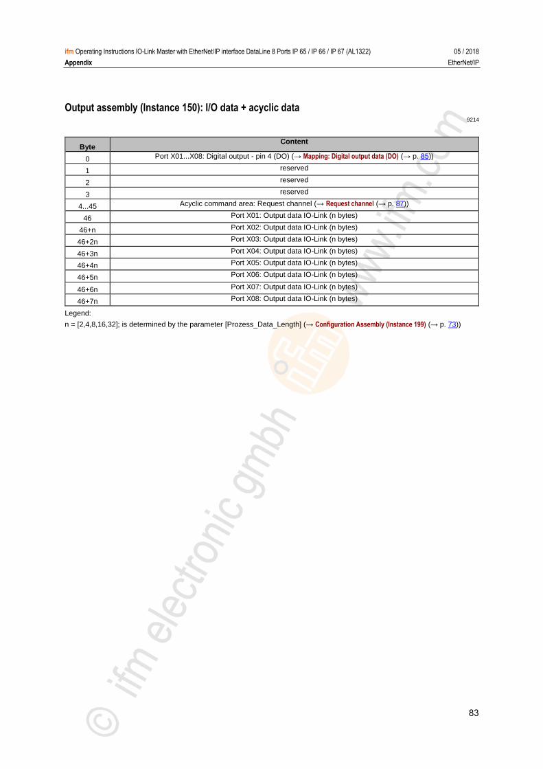
83
ifm Operating Instructions IO-Link Master with EtherNet/IP interface DataLine 8 Ports IP 65 / IP 66 / IP 67 (AL1322) 05 / 2018
Appendix EtherNet/IP
Output assembly (Instance 150): I/O data + acyclic data 9214
Byte Content
0 Port X01...X08: Digital output - pin 4 (DO) (→ Mapping: Digital output data (DO) (→ p. 85))
1 reserved
2 reserved
3 reserved
4...45 Acyclic command area: Request channel (→ Request channel (→ p. 87))
46 Port X01: Output data IO-Link (n bytes)
46+n Port X02: Output data IO-Link (n bytes)
46+2n Port X03: Output data IO-Link (n bytes)
46+3n Port X04: Output data IO-Link (n bytes)
46+4n Port X05: Output data IO-Link (n bytes)
46+5n Port X06: Output data IO-Link (n bytes)
46+6n Port X07: Output data IO-Link (n bytes)
46+7n Port X08: Output data IO-Link (n bytes)
Legend:
n = [2,4,8,16,32]; is determined by the parameter [Prozess_Data_Length] (→ Configuration Assembly (Instance 199) (→ p. 73))
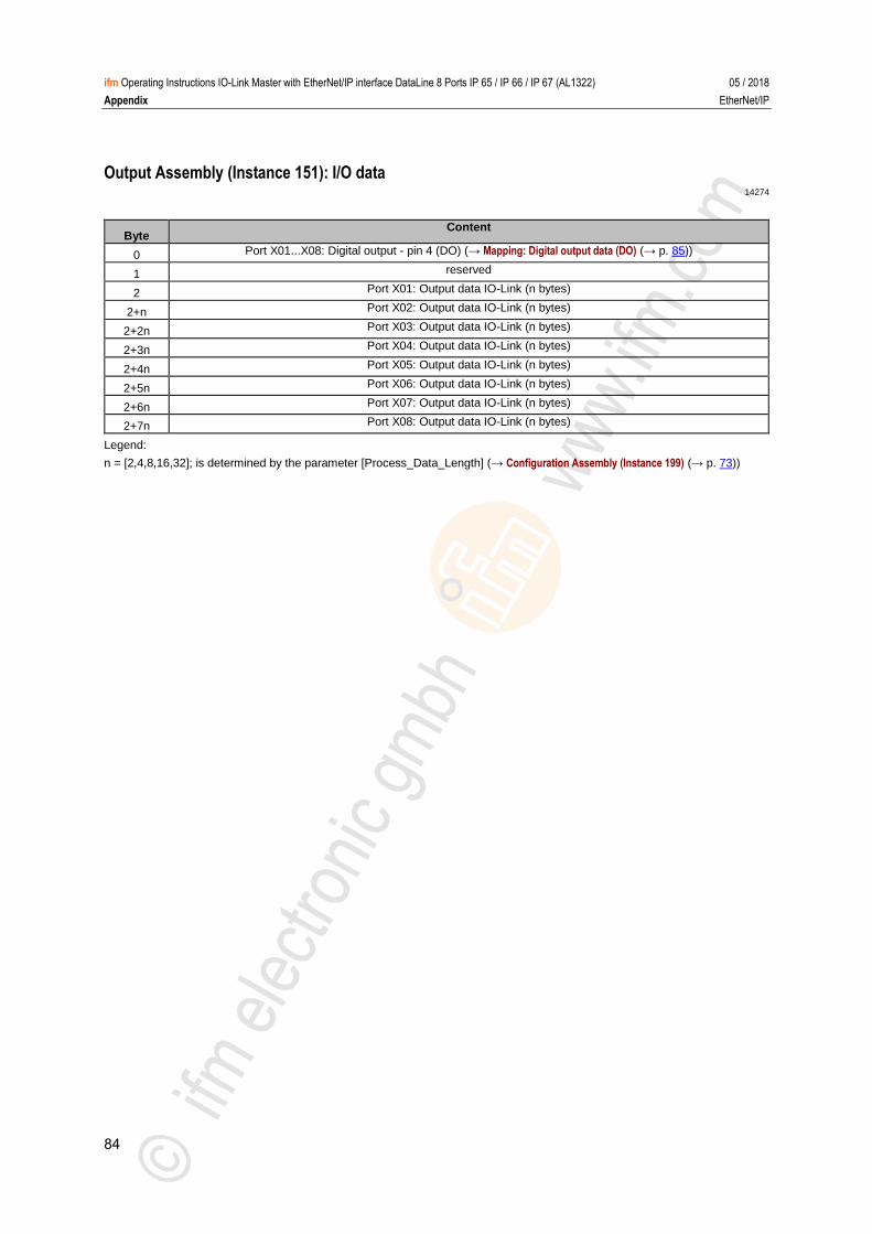
84
ifm Operating Instructions IO-Link Master with EtherNet/IP interface DataLine 8 Ports IP 65 / IP 66 / IP 67 (AL1322) 05 / 2018
Appendix EtherNet/IP
Output Assembly (Instance 151): I/O data 14274
Byte Content
0 Port X01...X08: Digital output - pin 4 (DO) (→ Mapping: Digital output data (DO) (→ p. 85))
1 reserved
2 Port X01: Output data IO-Link (n bytes)
2+n Port X02: Output data IO-Link (n bytes)
2+2n Port X03: Output data IO-Link (n bytes)
2+3n Port X04: Output data IO-Link (n bytes)
2+4n Port X05: Output data IO-Link (n bytes)
2+5n Port X06: Output data IO-Link (n bytes)
2+6n Port X07: Output data IO-Link (n bytes)
2+7n Port X08: Output data IO-Link (n bytes)
Legend:
n = [2,4,8,16,32]; is determined by the parameter [Process_Data_Length] (→ Configuration Assembly (Instance 199) (→ p. 73))

85
ifm Operating Instructions IO-Link Master with EtherNet/IP interface DataLine 8 Ports IP 65 / IP 66 / IP 67 (AL1322) 05 / 2018
Appendix EtherNet/IP
Mapping: Digital output data (DO) 19841
Bit 7 Bit 6 Bit 5 Bit 4 Bit 3 Bit 2 Bit 1 Bit 0
X08: pin 4 X07: pin 4 X06: pin4 X05: pin 4 X04: pin 4 X03: pin 4 X02: pin 4 X01: pin 4
Legend:
[pin 4] Signal level on pin 4 of the IO-Link port 1 bit 0x0 LOW
0x1 HIGH
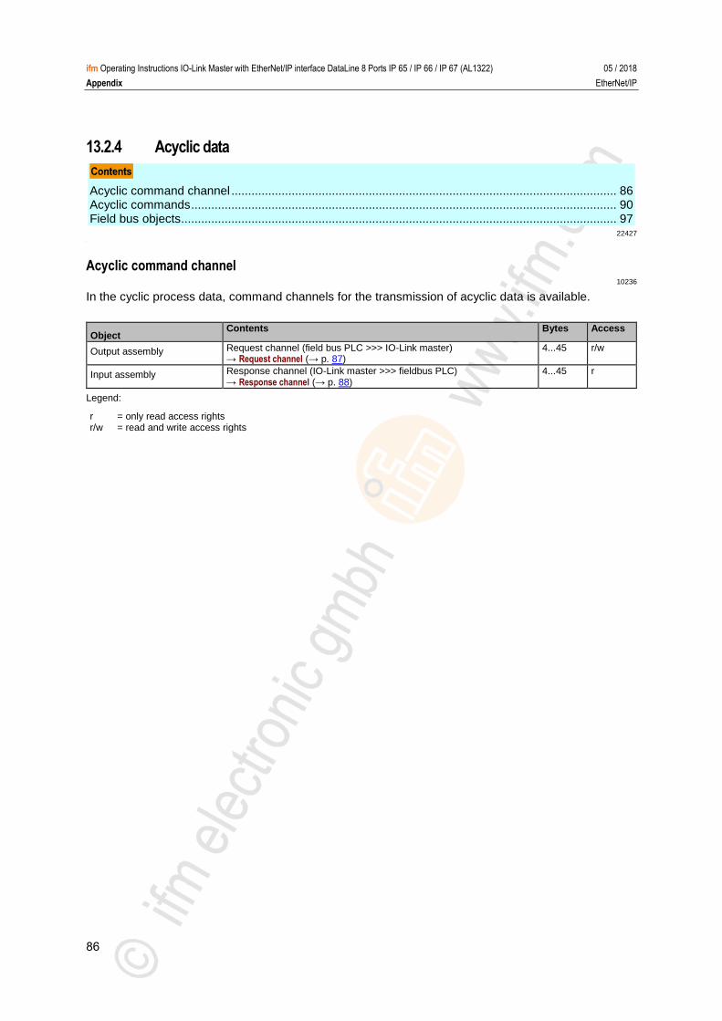
86
ifm Operating Instructions IO-Link Master with EtherNet/IP interface DataLine 8 Ports IP 65 / IP 66 / IP 67 (AL1322) 05 / 2018
Appendix EtherNet/IP
13.2.4 Acyclic data
Acyclic command channel ................................................................................................................... 86 Acyclic commands ............................................................................................................................... 90 Field bus objects .................................................................................................................................. 97
22427 >
Acyclic command channel 10236
In the cyclic process data, command channels for the transmission of acyclic data is available.
Object Contents Bytes Access
Output assembly Request channel (field bus PLC >>> IO-Link master) → Request channel (→ p. 87)
4...45 r/w
Input assembly Response channel (IO-Link master >>> fieldbus PLC) → Response channel (→ p. 88)
4...45 r
Legend:
r r/w
= only read access rights = read and write access rights
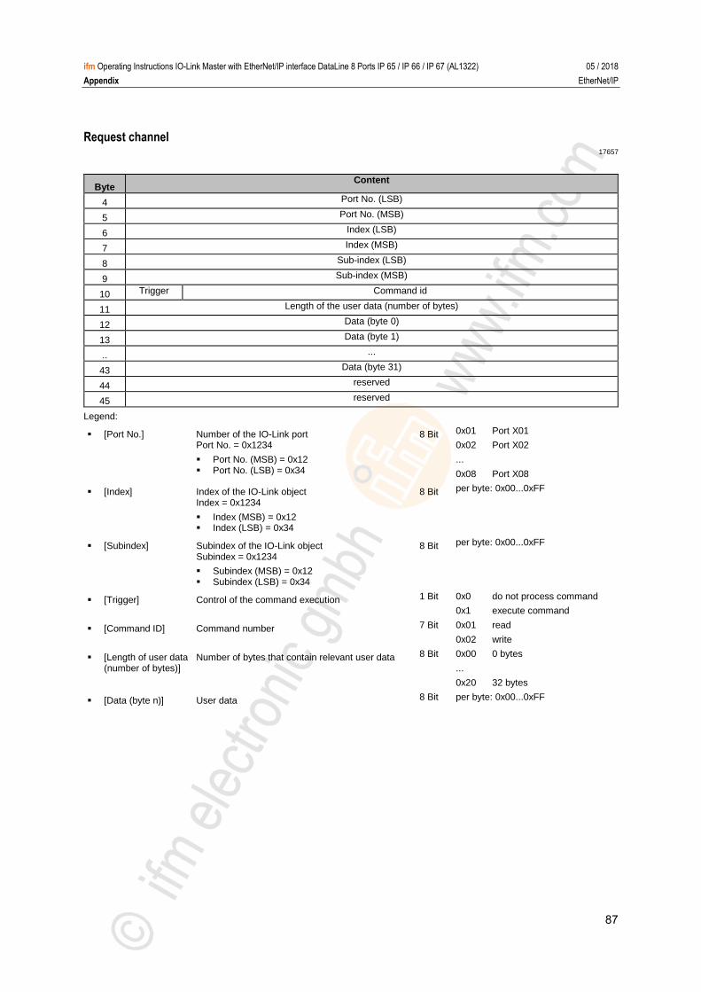
87
ifm Operating Instructions IO-Link Master with EtherNet/IP interface DataLine 8 Ports IP 65 / IP 66 / IP 67 (AL1322) 05 / 2018
Appendix EtherNet/IP
Request channel 17657
Byte Content
4 Port No. (LSB)
5 Port No. (MSB)
6 Index (LSB)
7 Index (MSB)
8 Sub-index (LSB)
9 Sub-index (MSB)
10 Trigger Command id
11 Length of the user data (number of bytes)
12 Data (byte 0)
13 Data (byte 1)
.. ...
43 Data (byte 31)
44 reserved
45 reserved
Legend:
[Port No.] Number of the IO-Link port Port No. = 0x1234
Port No. (MSB) = 0x12 Port No. (LSB) = 0x34
8 Bit 0x01 Port X01
0x02 Port X02
...
0x08 Port X08
[Index] Index of the IO-Link object Index = 0x1234
Index (MSB) = 0x12 Index (LSB) = 0x34
8 Bit per byte: 0x00...0xFF
[Subindex] Subindex of the IO-Link object Subindex = 0x1234
Subindex (MSB) = 0x12 Subindex (LSB) = 0x34
8 Bit per byte: 0x00...0xFF
[Trigger] Control of the command execution 1 Bit 0x0 do not process command
0x1 execute command
[Command ID] Command number 7 Bit 0x01 read
0x02 write
[Length of user data (number of bytes)]
Number of bytes that contain relevant user data 8 Bit 0x00 0 bytes
...
0x20 32 bytes
[Data (byte n)] User data 8 Bit per byte: 0x00...0xFF
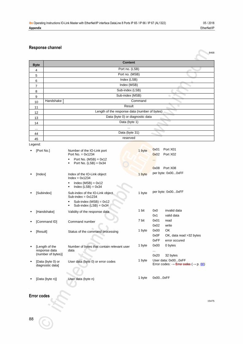
88
ifm Operating Instructions IO-Link Master with EtherNet/IP interface DataLine 8 Ports IP 65 / IP 66 / IP 67 (AL1322) 05 / 2018
Appendix EtherNet/IP
Response channel 8468
Byte Content
4 Port no. (LSB)
5 Port no. (MSB)
6 Index (LSB)
7 Index (MSB)
8 Sub-index (LSB)
9 Sub-index (MSB)
10 Handshake Command
11 Result
12 Length of the response data (number of bytes)
13 Data (byte 0) or diagnostic data
14 Data (byte 1)
... ...
44 Data (byte 31)
45 reserved
Legend:
[Port No.] Number of the IO-Link port Port No. = 0x1234
Port No. (MSB) = 0x12 Port No. (LSB) = 0x34
1 byte 0x01 Port X01
0x02 Port X02
...
0x08 Port X08
[Index] Index of the IO-Link object Index = 0x1234
Index (MSB) = 0x12 Index (LSB) = 0x34
1 byte per byte: 0x00...0xFF
[Subindex] Sub-index of the IO-Link object Sub-index = 0x1234
Sub-index (MSB) = 0x12 Sub-index (LSB) = 0x34
1 byte per byte: 0x00...0xFF
[Handshake] Validity of the response data 1 bit 0x0 invalid data
0x1 valid data
[Command ID] Command number 7 bit 0x01 read
0x02 write
[Result] Status of the command processing 1 byte 0x00 OK
0x0F OK, data read >32 bytes
0xFF error occured
[Length of the response data (number of bytes)]
Number of bytes that contain relevant user data
1 byte 0x00 0 bytes
...
0x20 32 bytes
[Data (byte 0) or diagnostic data]
User data (byte 0) or error codes 1 byte User data: 0x00...0xFF Error codes: → Error codes (→ p. 88)
[Data (byte n)] User data (byte n) 1 byte 0x00...0xFF
>
Error codes 15475

89
ifm Operating Instructions IO-Link Master with EtherNet/IP interface DataLine 8 Ports IP 65 / IP 66 / IP 67 (AL1322) 05 / 2018
Appendix EtherNet/IP
Error code Description
0x71 Service not available (unknown command has been sent to the IO-Link port)
0x72 Port blocked (another cyclic process accesses the IO-Link port)
0x74 Invalid data (wrong parameter has been sent in the command)
0x76 Wrong port (wrong port number)
0x77 Wrong port function (wrong port function or wrong parameter has been sent to the device)
0x78 Invalid length (set length is > 0x20)
0x80 Error in the device application; observe add. error codes (error codes: → description of IODD of the IO-Link device)

90
ifm Operating Instructions IO-Link Master with EtherNet/IP interface DataLine 8 Ports IP 65 / IP 66 / IP 67 (AL1322) 05 / 2018
Appendix EtherNet/IP
Acyclic commands
Command 0x10 – Set mode ................................................................................................................ 91 Command 0x20 – Set validation ID / data storage .............................................................................. 93 Command 0x30 – Set fail-safe data pattern ........................................................................................ 95
22631
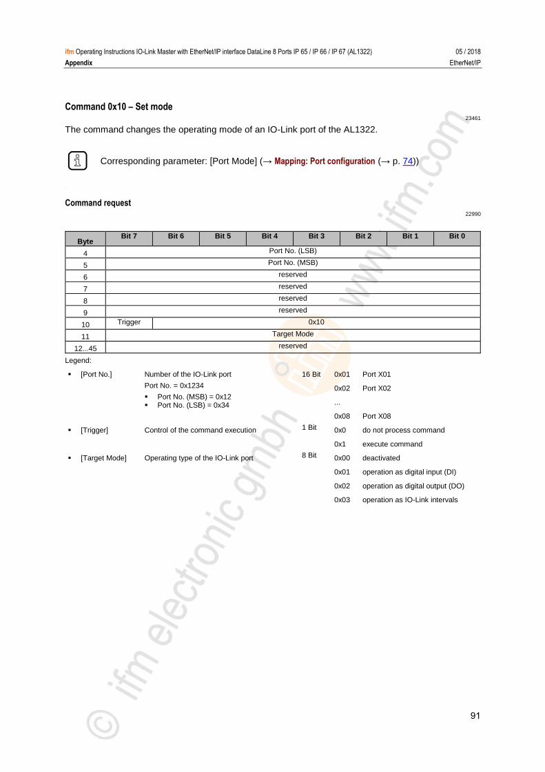
91
ifm Operating Instructions IO-Link Master with EtherNet/IP interface DataLine 8 Ports IP 65 / IP 66 / IP 67 (AL1322) 05 / 2018
Appendix EtherNet/IP
Command 0x10 – Set mode 23461
The command changes the operating mode of an IO-Link port of the AL1322.
Corresponding parameter: [Port Mode] (→ Mapping: Port configuration (→ p. 74))
>
Command request 22990
Byte Bit 7 Bit 6 Bit 5 Bit 4 Bit 3 Bit 2 Bit 1 Bit 0
4 Port No. (LSB)
5 Port No. (MSB)
6 reserved
7 reserved
8 reserved
9 reserved
10 Trigger 0x10
11 Target Mode
12...45 reserved
Legend:
[Port No.] Number of the IO-Link port
Port No. = 0x1234
Port No. (MSB) = 0x12 Port No. (LSB) = 0x34
16 Bit 0x01 Port X01
0x02 Port X02
...
0x08 Port X08
[Trigger] Control of the command execution 1 Bit 0x0 do not process command
0x1 execute command
[Target Mode] Operating type of the IO-Link port 8 Bit 0x00 deactivated
0x01 operation as digital input (DI)
0x02 operation as digital output (DO)
0x03 operation as IO-Link intervals
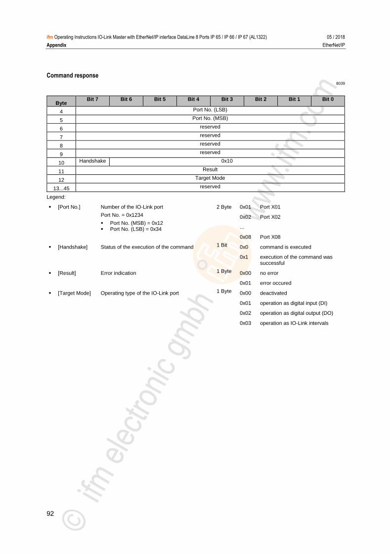
92
ifm Operating Instructions IO-Link Master with EtherNet/IP interface DataLine 8 Ports IP 65 / IP 66 / IP 67 (AL1322) 05 / 2018
Appendix EtherNet/IP
Command response 8039
Byte Bit 7 Bit 6 Bit 5 Bit 4 Bit 3 Bit 2 Bit 1 Bit 0
4 Port No. (LSB)
5 Port No. (MSB)
6 reserved
7 reserved
8 reserved
9 reserved
10 Handshake 0x10
11 Result
12 Target Mode
13...45 reserved
Legend:
[Port No.] Number of the IO-Link port
Port No. = 0x1234
Port No. (MSB) = 0x12 Port No. (LSB) = 0x34
2 Byte 0x01 Port X01
0x02 Port X02
...
0x08 Port X08
[Handshake] Status of the execution of the command 1 Bit 0x0 command is executed
0x1 execution of the command was successful
[Result] Error indication 1 Byte 0x00 no error
0x01 error occured
[Target Mode] Operating type of the IO-Link port 1 Byte 0x00 deactivated
0x01 operation as digital input (DI)
0x02 operation as digital output (DO)
0x03 operation as IO-Link intervals
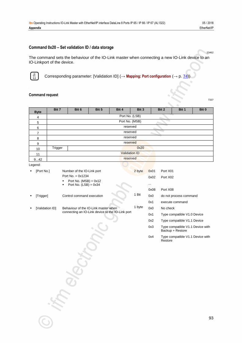
93
ifm Operating Instructions IO-Link Master with EtherNet/IP interface DataLine 8 Ports IP 65 / IP 66 / IP 67 (AL1322) 05 / 2018
Appendix EtherNet/IP
Command 0x20 – Set validation ID / data storage 23462
The command sets the behaviour of the IO-Link master when connecting a new IO-Link device to an IO-Linkport of the device.
Corresponding parameter: [Validation ID] (→ Mapping: Port configuration (→ p. 74))
>
Command request 7337
Byte Bit 7 Bit 6 Bit 5 Bit 4 Bit 3 Bit 2 Bit 1 Bit 0
4 Port No. (LSB)
5 Port No. (MSB)
6 reserved
7 reserved
8 reserved
9 reserved
10 Trigger 0x20
11 Validation ID
9...42 reserved
Legend:
[Port No.] Number of the IO-Link port
Port No. = 0x1234
Port No. (MSB) = 0x12 Port No. (LSB) = 0x34
2 byte 0x01 Port X01
0x02 Port X02
...
0x08 Port X08
[Trigger] Control command execution 1 Bit 0x0 do not process command
0x1 execute command
[Validation ID] Behaviour of the IO-Link master when connecting an IO-Link device to the IO-Link port
1 byte 0x0 No check
0x1 Type compatible V1.0 Device
0x2 Type compatible V1.1 Device
0x3 Type compatible V1.1 Device with Backup + Restore
0x4 Type compatible V1.1 Device with Restore
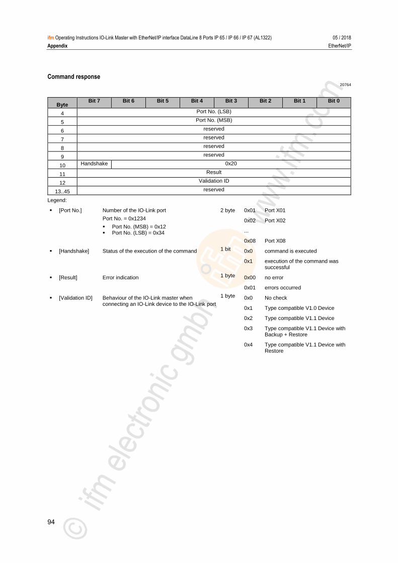
94
ifm Operating Instructions IO-Link Master with EtherNet/IP interface DataLine 8 Ports IP 65 / IP 66 / IP 67 (AL1322) 05 / 2018
Appendix EtherNet/IP
Command response 20764
Byte Bit 7 Bit 6 Bit 5 Bit 4 Bit 3 Bit 2 Bit 1 Bit 0
4 Port No. (LSB)
5 Port No. (MSB)
6 reserved
7 reserved
8 reserved
9 reserved
10 Handshake 0x20
11 Result
12 Validation ID
13..45 reserved
Legend:
[Port No.] Number of the IO-Link port
Port No. = 0x1234
Port No. (MSB) = 0x12 Port No. (LSB) = 0x34
2 byte 0x01 Port X01
0x02 Port X02
...
0x08 Port X08
[Handshake] Status of the execution of the command 1 bit 0x0 command is executed
0x1 execution of the command was successful
[Result] Error indication 1 byte 0x00 no error
0x01 errors occurred
[Validation ID] Behaviour of the IO-Link master when connecting an IO-Link device to the IO-Link port
1 byte 0x0 No check
0x1 Type compatible V1.0 Device
0x2 Type compatible V1.1 Device
0x3 Type compatible V1.1 Device with Backup + Restore
0x4 Type compatible V1.1 Device with Restore
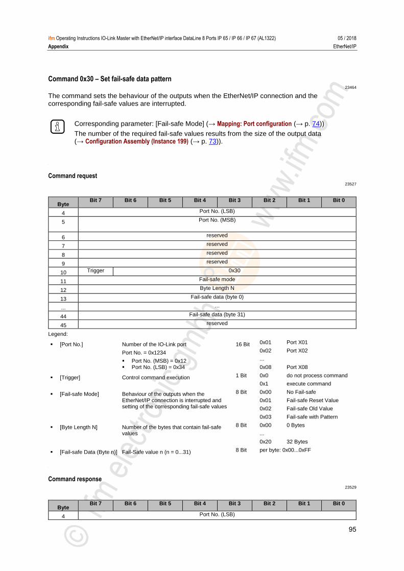
95
ifm Operating Instructions IO-Link Master with EtherNet/IP interface DataLine 8 Ports IP 65 / IP 66 / IP 67 (AL1322) 05 / 2018
Appendix EtherNet/IP
Command 0x30 – Set fail-safe data pattern 23464
The command sets the behaviour of the outputs when the EtherNet/IP connection and the corresponding fail-safe values are interrupted.
Corresponding parameter: [Fail-safe Mode] (→ Mapping: Port configuration (→ p. 74))
The number of the required fail-safe values results from the size of the output data (→ Configuration Assembly (Instance 199) (→ p. 73)).
>
Command request 23527
Byte Bit 7 Bit 6 Bit 5 Bit 4 Bit 3 Bit 2 Bit 1 Bit 0
4 Port No. (LSB)
5 Port No. (MSB)
6 reserved
7 reserved
8 reserved
9 reserved
10 Trigger 0x30
11 Fail-safe mode
12 Byte Length N
13 Fail-safe data (byte 0)
... ...
44 Fail-safe data (byte 31)
45 reserved
Legend:
[Port No.] Number of the IO-Link port
Port No. = 0x1234
Port No. (MSB) = 0x12 Port No. (LSB) = 0x34
16 Bit 0x01 Port X01
0x02 Port X02
...
0x08 Port X08
[Trigger] Control command execution 1 Bit 0x0 do not process command
0x1 execute command
[Fail-safe Mode] Behaviour of the outputs when the EtherNet/IP connection is interrupted and setting of the corresponding fail-safe values
8 Bit 0x00 No Fail-safe
0x01 Fail-safe Reset Value
0x02 Fail-safe Old Value
0x03 Fail-safe with Pattern
[Byte Length N] Number of the bytes that contain fail-safe values
8 Bit 0x00 0 Bytes
...
0x20 32 Bytes
[Fail-safe Data (Byte n)] Fail-Safe value n (n = 0...31) 8 Bit per byte: 0x00...0xFF
>
Command response 23529
Byte Bit 7 Bit 6 Bit 5 Bit 4 Bit 3 Bit 2 Bit 1 Bit 0
4 Port No. (LSB)
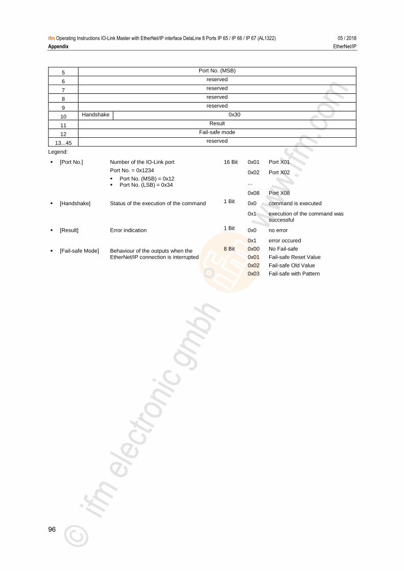
96
ifm Operating Instructions IO-Link Master with EtherNet/IP interface DataLine 8 Ports IP 65 / IP 66 / IP 67 (AL1322) 05 / 2018
Appendix EtherNet/IP
5 Port No. (MSB)
6 reserved
7 reserved
8 reserved
9 reserved
10 Handshake 0x30
11 Result
12 Fail-safe mode
13...45 reserved
Legend:
[Port No.] Number of the IO-Link port
Port No. = 0x1234
Port No. (MSB) = 0x12 Port No. (LSB) = 0x34
16 Bit 0x01 Port X01
0x02 Port X02
...
0x08 Port X08
[Handshake] Status of the execution of the command 1 Bit 0x0 command is executed
0x1 execution of the command was successful
[Result] Error indication 1 Bit 0x0 no error
0x1 error occured
[Fail-safe Mode] Behaviour of the outputs when the EtherNet/IP connection is interrupted
8 Bit 0x00 No Fail-safe
0x01 Fail-safe Reset Value
0x02 Fail-safe Old Value
0x03 Fail-safe with Pattern
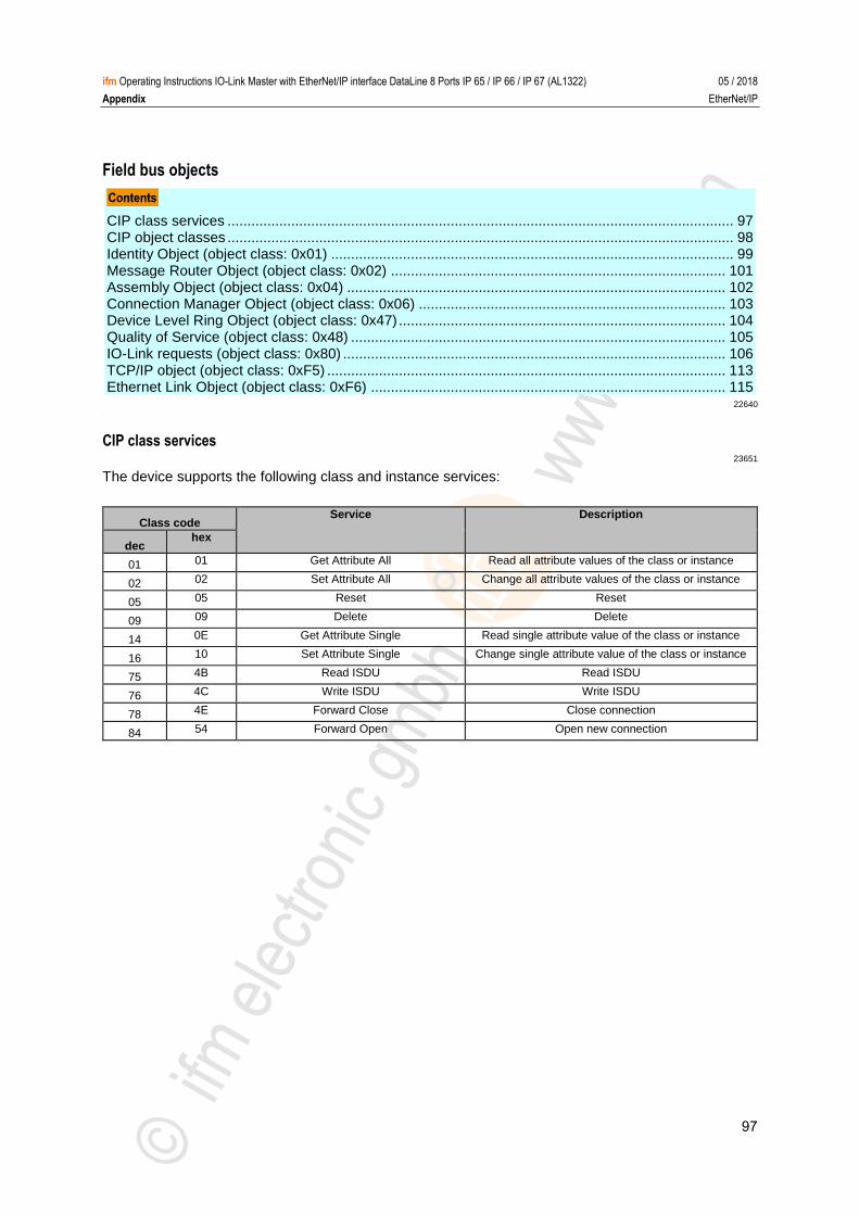
97
ifm Operating Instructions IO-Link Master with EtherNet/IP interface DataLine 8 Ports IP 65 / IP 66 / IP 67 (AL1322) 05 / 2018
Appendix EtherNet/IP
Field bus objects
CIP class services ............................................................................................................................... 97 CIP object classes ............................................................................................................................... 98 Identity Object (object class: 0x01) ..................................................................................................... 99 Message Router Object (object class: 0x02) .................................................................................... 101 Assembly Object (object class: 0x04) ............................................................................................... 102 Connection Manager Object (object class: 0x06) ............................................................................. 103 Device Level Ring Object (object class: 0x47) .................................................................................. 104 Quality of Service (object class: 0x48) .............................................................................................. 105 IO-Link requests (object class: 0x80) ................................................................................................ 106 TCP/IP object (object class: 0xF5) .................................................................................................... 113 Ethernet Link Object (object class: 0xF6) ......................................................................................... 115
22640 >
CIP class services 23651
The device supports the following class and instance services:
Class code Service Description
dec hex
01 01 Get Attribute All Read all attribute values of the class or instance
02 02 Set Attribute All Change all attribute values of the class or instance
05 05 Reset Reset
09 09 Delete Delete
14 0E Get Attribute Single Read single attribute value of the class or instance
16 10 Set Attribute Single Change single attribute value of the class or instance
75 4B Read ISDU Read ISDU
76 4C Write ISDU Write ISDU
78 4E Forward Close Close connection
84 54 Forward Open Open new connection
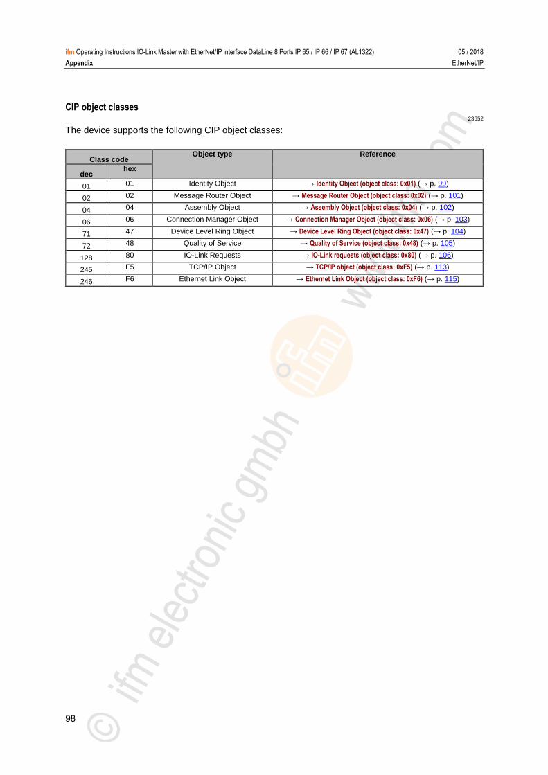
98
ifm Operating Instructions IO-Link Master with EtherNet/IP interface DataLine 8 Ports IP 65 / IP 66 / IP 67 (AL1322) 05 / 2018
Appendix EtherNet/IP
CIP object classes 23652
The device supports the following CIP object classes:
Class code Object type Reference
dec hex
01 01 Identity Object → Identity Object (object class: 0x01) (→ p. 99)
02 02 Message Router Object → Message Router Object (object class: 0x02) (→ p. 101)
04 04 Assembly Object → Assembly Object (object class: 0x04) (→ p. 102)
06 06 Connection Manager Object → Connection Manager Object (object class: 0x06) (→ p. 103)
71 47 Device Level Ring Object → Device Level Ring Object (object class: 0x47) (→ p. 104)
72 48 Quality of Service → Quality of Service (object class: 0x48) (→ p. 105)
128 80 IO-Link Requests → IO-Link requests (object class: 0x80) (→ p. 106)
245 F5 TCP/IP Object → TCP/IP object (object class: 0xF5) (→ p. 113)
246 F6 Ethernet Link Object → Ethernet Link Object (object class: 0xF6) (→ p. 115)
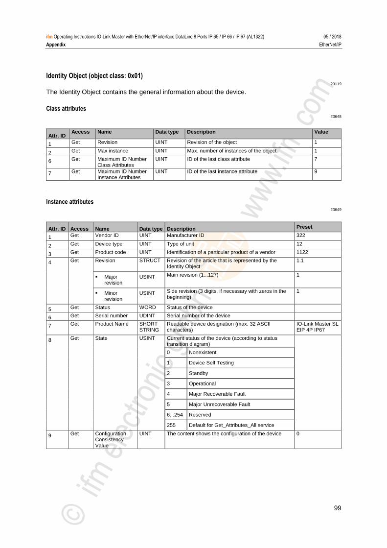
99
ifm Operating Instructions IO-Link Master with EtherNet/IP interface DataLine 8 Ports IP 65 / IP 66 / IP 67 (AL1322) 05 / 2018
Appendix EtherNet/IP
Identity Object (object class: 0x01) 23119
The Identity Object contains the general information about the device. >
Class attributes 23648
Attr. ID Access Name Data type Description Value
1 Get Revision UINT Revision of the object 1
2 Get Max instance UINT Max. number of instances of the object 1
6 Get Maximum ID Number Class Attributes
UINT ID of the last class attribute 7
7 Get Maximum ID Number Instance Attributes
UINT ID of the last instance attribute 9
>
Instance attributes 23649
Attr. ID Access Name Data type Description Preset
1 Get Vendor ID UINT Manufacturer ID 322
2 Get Device type UINT Type of unit 12
3 Get Product code UINT Identification of a particular product of a vendor 1122
4 Get Revision STRUCT Revision of the article that is represented by the Identity Object
1.1
Major revision
USINT Main revision (1...127) 1
Minor revision
USINT Side revision (3 digits, if necessary with zeros in the beginning)
1
5 Get Status WORD Status of the device
6 Get Serial number UDINT Serial number of the device
7 Get Product Name SHORT STRING
Readable device designation (max. 32 ASCII characters)
IO-Link Master SL EIP 4P IP67
8 Get State USINT Current status of the device (according to status transition diagram)
0 Nonexistent
1 Device Self Testing
2 Standby
3 Operational
4 Major Recoverable Fault
5 Major Unrecoverable Fault
6...254 Reserved
255 Default for Get_Attributes_All service
9 Get Configuration Consistency Value
UINT The content shows the configuration of the device 0
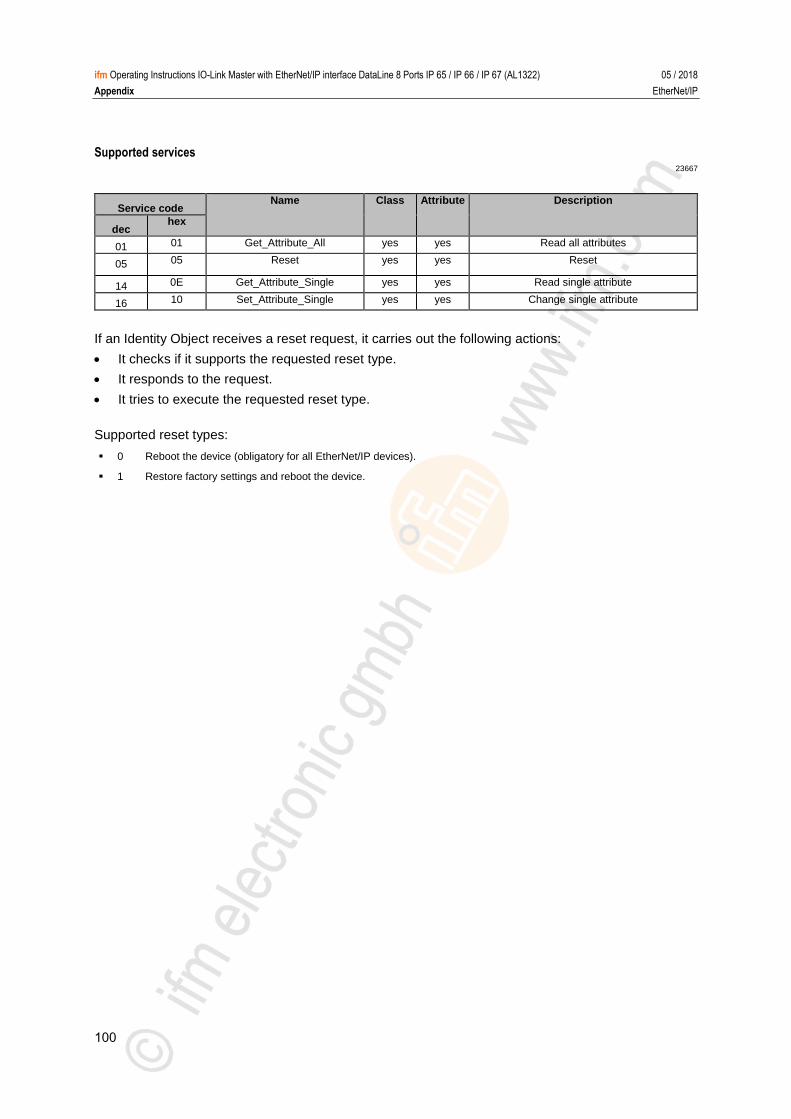
100
ifm Operating Instructions IO-Link Master with EtherNet/IP interface DataLine 8 Ports IP 65 / IP 66 / IP 67 (AL1322) 05 / 2018
Appendix EtherNet/IP
Supported services 23667
Service code Name Class Attribute Description
dec hex
01 01 Get_Attribute_All yes yes Read all attributes
05 05 Reset yes yes Reset
14 0E Get_Attribute_Single yes yes Read single attribute
16 10 Set_Attribute_Single yes yes Change single attribute
If an Identity Object receives a reset request, it carries out the following actions:
It checks if it supports the requested reset type.
It responds to the request.
It tries to execute the requested reset type.
Supported reset types:
0 Reboot the device (obligatory for all EtherNet/IP devices).
1 Restore factory settings and reboot the device.
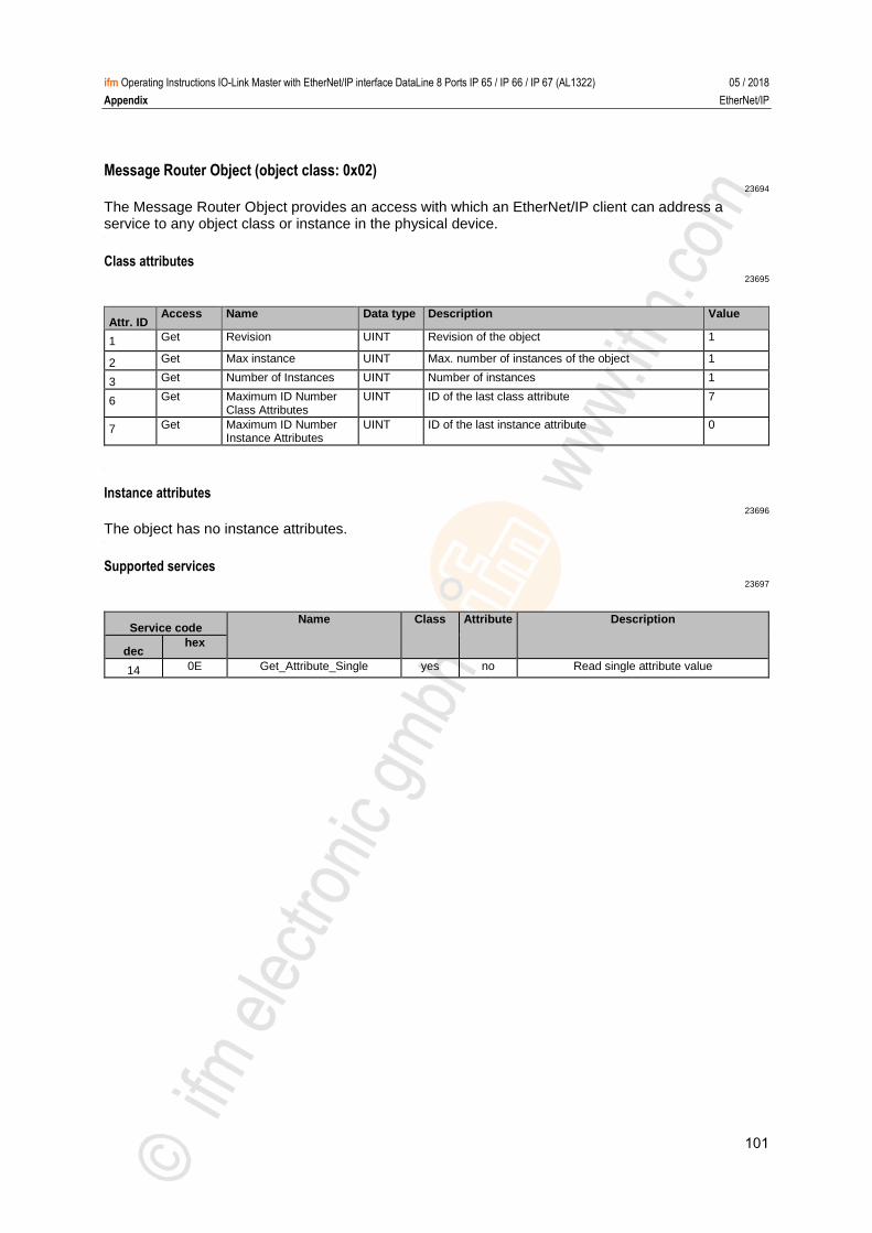
101
ifm Operating Instructions IO-Link Master with EtherNet/IP interface DataLine 8 Ports IP 65 / IP 66 / IP 67 (AL1322) 05 / 2018
Appendix EtherNet/IP
Message Router Object (object class: 0x02) 23694
The Message Router Object provides an access with which an EtherNet/IP client can address a service to any object class or instance in the physical device. >
Class attributes 23695
Attr. ID Access Name Data type Description Value
1 Get Revision UINT Revision of the object 1
2 Get Max instance UINT Max. number of instances of the object 1
3 Get Number of Instances UINT Number of instances 1
6 Get Maximum ID Number Class Attributes
UINT ID of the last class attribute 7
7 Get Maximum ID Number Instance Attributes
UINT ID of the last instance attribute 0
>
Instance attributes 23696
The object has no instance attributes. >
Supported services 23697
Service code Name Class Attribute Description
dec hex
14 0E Get_Attribute_Single yes no Read single attribute value
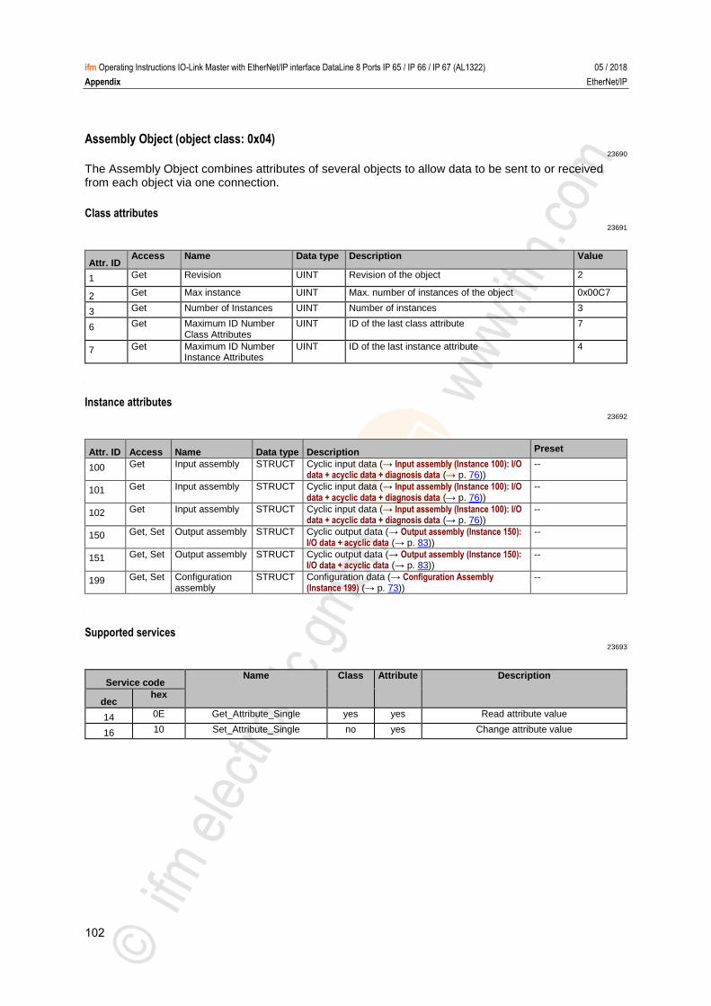
102
ifm Operating Instructions IO-Link Master with EtherNet/IP interface DataLine 8 Ports IP 65 / IP 66 / IP 67 (AL1322) 05 / 2018
Appendix EtherNet/IP
Assembly Object (object class: 0x04) 23690
The Assembly Object combines attributes of several objects to allow data to be sent to or received from each object via one connection. >
Class attributes 23691
Attr. ID Access Name Data type Description Value
1 Get Revision UINT Revision of the object 2
2 Get Max instance UINT Max. number of instances of the object 0x00C7
3 Get Number of Instances UINT Number of instances 3
6 Get Maximum ID Number Class Attributes
UINT ID of the last class attribute 7
7 Get Maximum ID Number Instance Attributes
UINT ID of the last instance attribute 4
>
Instance attributes 23692
Attr. ID Access Name Data type Description Preset
100 Get Input assembly STRUCT Cyclic input data (→ Input assembly (Instance 100): I/O data + acyclic data + diagnosis data (→ p. 76))
--
101 Get Input assembly STRUCT Cyclic input data (→ Input assembly (Instance 100): I/O data + acyclic data + diagnosis data (→ p. 76))
--
102 Get Input assembly STRUCT Cyclic input data (→ Input assembly (Instance 100): I/O data + acyclic data + diagnosis data (→ p. 76))
--
150 Get, Set Output assembly STRUCT Cyclic output data (→ Output assembly (Instance 150): I/O data + acyclic data (→ p. 83))
--
151 Get, Set Output assembly STRUCT Cyclic output data (→ Output assembly (Instance 150): I/O data + acyclic data (→ p. 83))
--
199 Get, Set Configuration assembly
STRUCT Configuration data (→ Configuration Assembly (Instance 199) (→ p. 73))
--
>
Supported services 23693
Service code Name Class Attribute Description
dec hex
14 0E Get_Attribute_Single yes yes Read attribute value
16 10 Set_Attribute_Single no yes Change attribute value
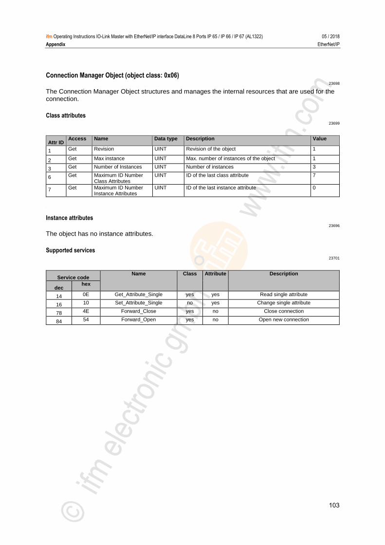
103
ifm Operating Instructions IO-Link Master with EtherNet/IP interface DataLine 8 Ports IP 65 / IP 66 / IP 67 (AL1322) 05 / 2018
Appendix EtherNet/IP
Connection Manager Object (object class: 0x06) 23698
The Connection Manager Object structures and manages the internal resources that are used for the connection. >
Class attributes 23699
Attr ID Access Name Data type Description Value
1 Get Revision UINT Revision of the object 1
2 Get Max instance UINT Max. number of instances of the object 1
3 Get Number of Instances UINT Number of instances 3
6 Get Maximum ID Number Class Attributes
UINT ID of the last class attribute 7
7 Get Maximum ID Number Instance Attributes
UINT ID of the last instance attribute 0
>
Instance attributes 23696
The object has no instance attributes. >
Supported services 23701
Service code Name Class Attribute Description
dec hex
14 0E Get_Attribute_Single yes yes Read single attribute
16 10 Set_Attribute_Single no yes Change single attribute
78 4E Forward_Close yes no Close connection
84 54 Forward_Open yes no Open new connection
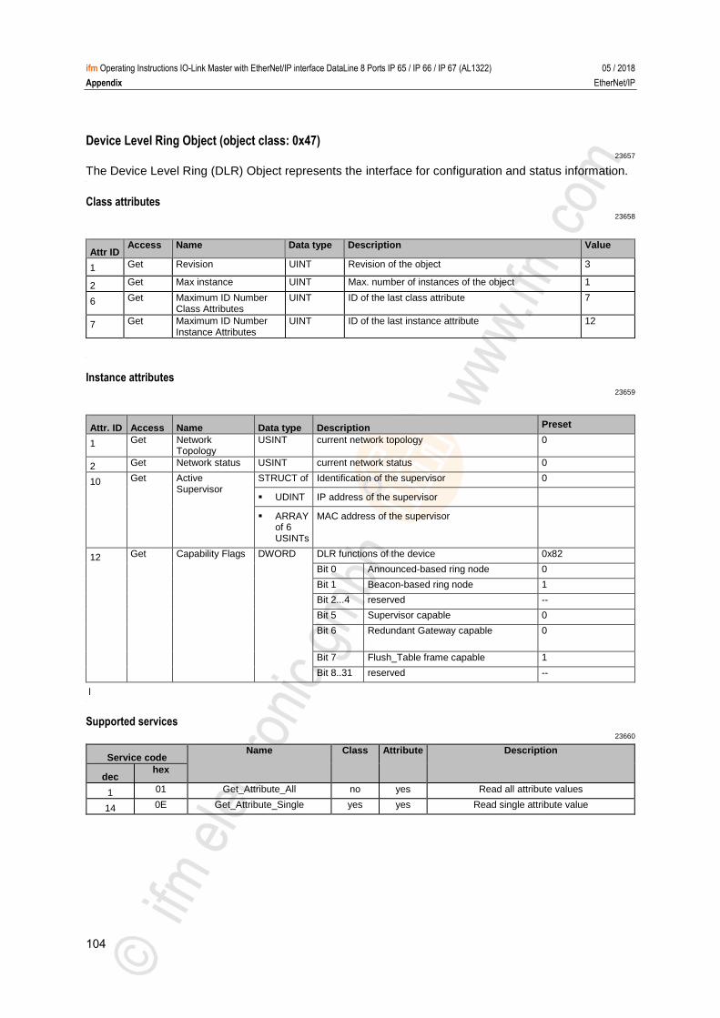
104
ifm Operating Instructions IO-Link Master with EtherNet/IP interface DataLine 8 Ports IP 65 / IP 66 / IP 67 (AL1322) 05 / 2018
Appendix EtherNet/IP
Device Level Ring Object (object class: 0x47) 23657
The Device Level Ring (DLR) Object represents the interface for configuration and status information. >
Class attributes 23658
Attr ID Access Name Data type Description Value
1 Get Revision UINT Revision of the object 3
2 Get Max instance UINT Max. number of instances of the object 1
6 Get Maximum ID Number Class Attributes
UINT ID of the last class attribute 7
7 Get Maximum ID Number Instance Attributes
UINT ID of the last instance attribute 12
>
Instance attributes 23659
Attr. ID Access Name Data type Description Preset
1 Get Network Topology
USINT current network topology 0
2 Get Network status USINT current network status 0
10 Get Active Supervisor
STRUCT of Identification of the supervisor 0
UDINT IP address of the supervisor
ARRAY of 6 USINTs
MAC address of the supervisor
12 Get Capability Flags DWORD DLR functions of the device 0x82
Bit 0 Announced-based ring node 0
Bit 1 Beacon-based ring node 1
Bit 2...4 reserved --
Bit 5 Supervisor capable 0
Bit 6 Redundant Gateway capable 0
Bit 7 Flush_Table frame capable 1
Bit 8..31 reserved --
l >
Supported services 23660
Service code Name Class Attribute Description
dec hex
1 01 Get_Attribute_All no yes Read all attribute values
14 0E Get_Attribute_Single yes yes Read single attribute value
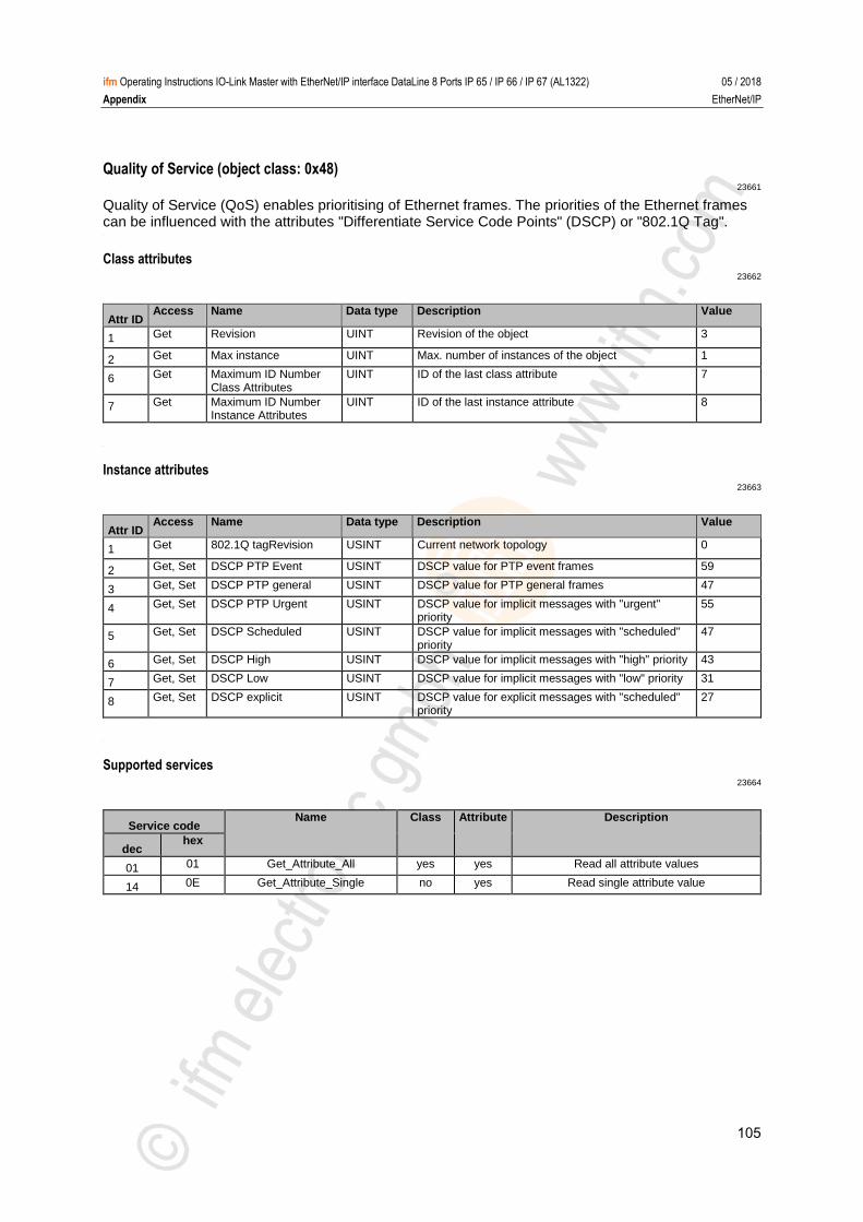
105
ifm Operating Instructions IO-Link Master with EtherNet/IP interface DataLine 8 Ports IP 65 / IP 66 / IP 67 (AL1322) 05 / 2018
Appendix EtherNet/IP
Quality of Service (object class: 0x48) 23661
Quality of Service (QoS) enables prioritising of Ethernet frames. The priorities of the Ethernet frames can be influenced with the attributes "Differentiate Service Code Points" (DSCP) or "802.1Q Tag". >
Class attributes 23662
Attr ID Access Name Data type Description Value
1 Get Revision UINT Revision of the object 3
2 Get Max instance UINT Max. number of instances of the object 1
6 Get Maximum ID Number Class Attributes
UINT ID of the last class attribute 7
7 Get Maximum ID Number Instance Attributes
UINT ID of the last instance attribute 8
>
Instance attributes 23663
Attr ID Access Name Data type Description Value
1 Get 802.1Q tagRevision USINT Current network topology 0
2 Get, Set DSCP PTP Event USINT DSCP value for PTP event frames 59
3 Get, Set DSCP PTP general USINT DSCP value for PTP general frames 47
4 Get, Set DSCP PTP Urgent USINT DSCP value for implicit messages with "urgent" priority
55
5 Get, Set DSCP Scheduled USINT DSCP value for implicit messages with "scheduled" priority
47
6 Get, Set DSCP High USINT DSCP value for implicit messages with "high" priority 43
7 Get, Set DSCP Low USINT DSCP value for implicit messages with "low" priority 31
8 Get, Set DSCP explicit USINT DSCP value for explicit messages with "scheduled" priority
27
>
Supported services 23664
Service code Name Class Attribute Description
dec hex
01 01 Get_Attribute_All yes yes Read all attribute values
14 0E Get_Attribute_Single no yes Read single attribute value
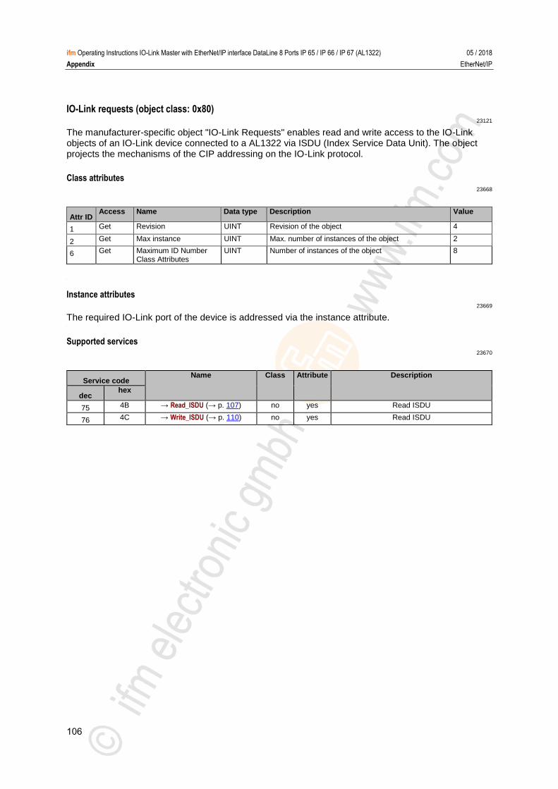
106
ifm Operating Instructions IO-Link Master with EtherNet/IP interface DataLine 8 Ports IP 65 / IP 66 / IP 67 (AL1322) 05 / 2018
Appendix EtherNet/IP
IO-Link requests (object class: 0x80) 23121
The manufacturer-specific object "IO-Link Requests" enables read and write access to the IO-Link objects of an IO-Link device connected to a AL1322 via ISDU (Index Service Data Unit). The object projects the mechanisms of the CIP addressing on the IO-Link protocol. >
Class attributes 23668
Attr ID Access Name Data type Description Value
1 Get Revision UINT Revision of the object 4
2 Get Max instance UINT Max. number of instances of the object 2
6 Get Maximum ID Number Class Attributes
UINT Number of instances of the object 8
>
Instance attributes 23669
The required IO-Link port of the device is addressed via the instance attribute. >
Supported services 23670
Service code Name Class Attribute Description
dec hex
75 4B → Read_ISDU (→ p. 107) no yes Read ISDU
76 4C → Write_ISDU (→ p. 110) no yes Read ISDU
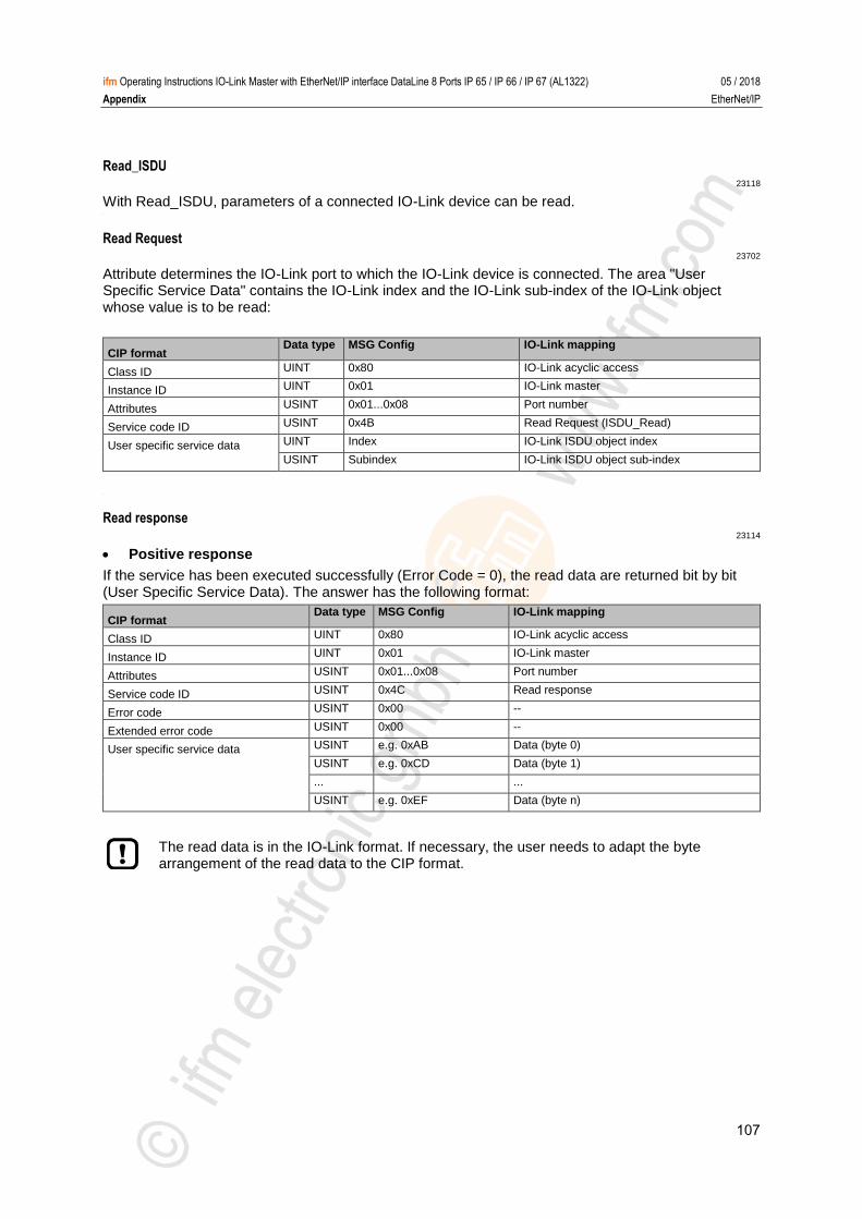
107
ifm Operating Instructions IO-Link Master with EtherNet/IP interface DataLine 8 Ports IP 65 / IP 66 / IP 67 (AL1322) 05 / 2018
Appendix EtherNet/IP
Read_ISDU 23118
With Read_ISDU, parameters of a connected IO-Link device can be read. >
Read Request 23702
Attribute determines the IO-Link port to which the IO-Link device is connected. The area "User Specific Service Data" contains the IO-Link index and the IO-Link sub-index of the IO-Link object whose value is to be read:
CIP format Data type MSG Config IO-Link mapping
Class ID UINT 0x80 IO-Link acyclic access
Instance ID UINT 0x01 IO-Link master
Attributes USINT 0x01...0x08 Port number
Service code ID USINT 0x4B Read Request (ISDU_Read)
User specific service data UINT Index IO-Link ISDU object index
USINT Subindex IO-Link ISDU object sub-index
>
Read response 23114
Positive response
If the service has been executed successfully (Error Code = 0), the read data are returned bit by bit (User Specific Service Data). The answer has the following format:
CIP format Data type MSG Config IO-Link mapping
Class ID UINT 0x80 IO-Link acyclic access
Instance ID UINT 0x01 IO-Link master
Attributes USINT 0x01...0x08 Port number
Service code ID USINT 0x4C Read response
Error code USINT 0x00 --
Extended error code USINT 0x00 --
User specific service data USINT e.g. 0xAB Data (byte 0)
USINT e.g. 0xCD Data (byte 1)
... ...
USINT e.g. 0xEF Data (byte n)
The read data is in the IO-Link format. If necessary, the user needs to adapt the byte arrangement of the read data to the CIP format.
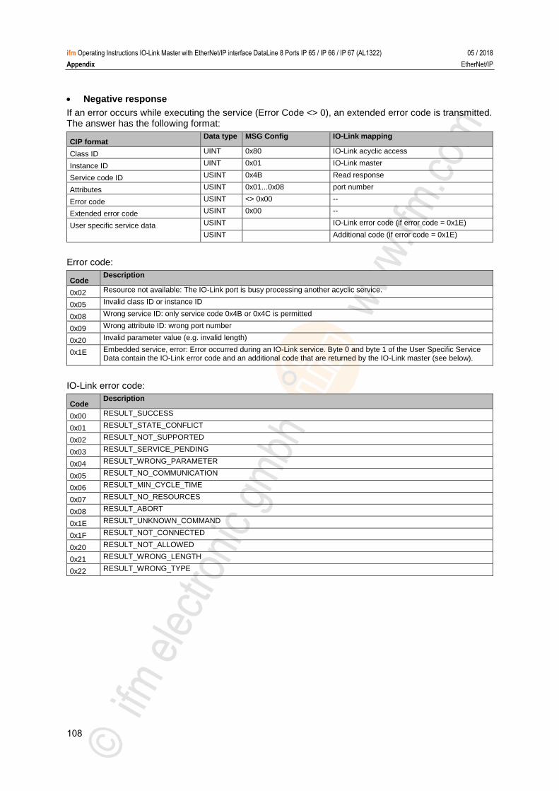
108
ifm Operating Instructions IO-Link Master with EtherNet/IP interface DataLine 8 Ports IP 65 / IP 66 / IP 67 (AL1322) 05 / 2018
Appendix EtherNet/IP
Negative response
If an error occurs while executing the service (Error Code <> 0), an extended error code is transmitted. The answer has the following format:
CIP format Data type MSG Config IO-Link mapping
Class ID UINT 0x80 IO-Link acyclic access
Instance ID UINT 0x01 IO-Link master
Service code ID USINT 0x4B Read response
Attributes USINT 0x01...0x08 port number
Error code USINT <> 0x00 --
Extended error code USINT 0x00 --
User specific service data USINT IO-Link error code (if error code = 0x1E)
USINT Additional code (if error code = 0x1E)
Error code:
Code Description
0x02 Resource not available: The IO-Link port is busy processing another acyclic service.
0x05 Invalid class ID or instance ID
0x08 Wrong service ID: only service code 0x4B or 0x4C is permitted
0x09 Wrong attribute ID: wrong port number
0x20 Invalid parameter value (e.g. invalid length)
0x1E Embedded service, error: Error occurred during an IO-Link service. Byte 0 and byte 1 of the User Specific Service Data contain the IO-Link error code and an additional code that are returned by the IO-Link master (see below).
IO-Link error code:
Code Description
0x00 RESULT_SUCCESS
0x01 RESULT_STATE_CONFLICT
0x02 RESULT_NOT_SUPPORTED
0x03 RESULT_SERVICE_PENDING
0x04 RESULT_WRONG_PARAMETER
0x05 RESULT_NO_COMMUNICATION
0x06 RESULT_MIN_CYCLE_TIME
0x07 RESULT_NO_RESOURCES
0x08 RESULT_ABORT
0x1E RESULT_UNKNOWN_COMMAND
0x1F RESULT_NOT_CONNECTED
0x20 RESULT_NOT_ALLOWED
0x21 RESULT_WRONG_LENGTH
0x22 RESULT_WRONG_TYPE
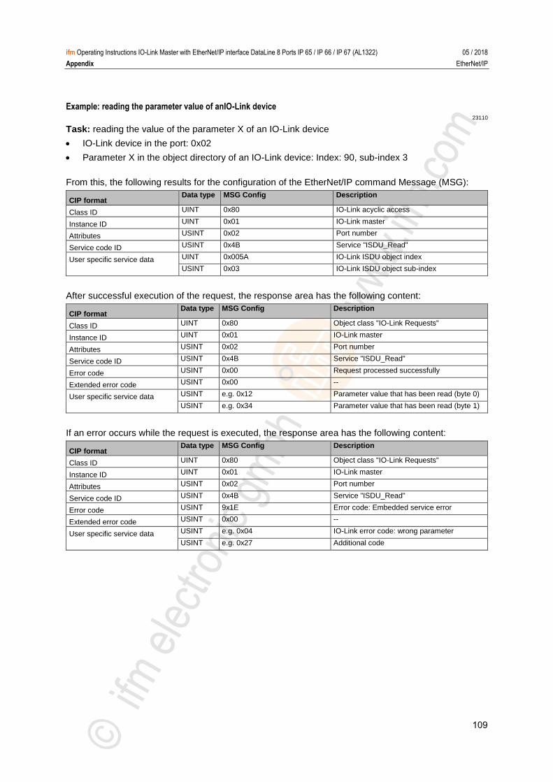
109
ifm Operating Instructions IO-Link Master with EtherNet/IP interface DataLine 8 Ports IP 65 / IP 66 / IP 67 (AL1322) 05 / 2018
Appendix EtherNet/IP
Example: reading the parameter value of anIO-Link device 23110
Task: reading the value of the parameter X of an IO-Link device
IO-Link device in the port: 0x02
Parameter X in the object directory of an IO-Link device: Index: 90, sub-index 3
From this, the following results for the configuration of the EtherNet/IP command Message (MSG):
CIP format Data type MSG Config Description
Class ID UINT 0x80 IO-Link acyclic access
Instance ID UINT 0x01 IO-Link master
Attributes USINT 0x02 Port number
Service code ID USINT 0x4B Service "ISDU_Read"
User specific service data UINT 0x005A IO-Link ISDU object index
USINT 0x03 IO-Link ISDU object sub-index
After successful execution of the request, the response area has the following content:
CIP format Data type MSG Config Description
Class ID UINT 0x80 Object class "IO-Link Requests"
Instance ID UINT 0x01 IO-Link master
Attributes USINT 0x02 Port number
Service code ID USINT 0x4B Service "ISDU_Read"
Error code USINT 0x00 Request processed successfully
Extended error code USINT 0x00 --
User specific service data USINT e.g. 0x12 Parameter value that has been read (byte 0)
USINT e.g. 0x34 Parameter value that has been read (byte 1)
If an error occurs while the request is executed, the response area has the following content:
CIP format Data type MSG Config Description
Class ID UINT 0x80 Object class "IO-Link Requests"
Instance ID UINT 0x01 IO-Link master
Attributes USINT 0x02 Port number
Service code ID USINT 0x4B Service "ISDU_Read"
Error code USINT 9x1E Error code: Embedded service error
Extended error code USINT 0x00 --
User specific service data USINT e.g. 0x04 IO-Link error code: wrong parameter
USINT e.g. 0x27 Additional code
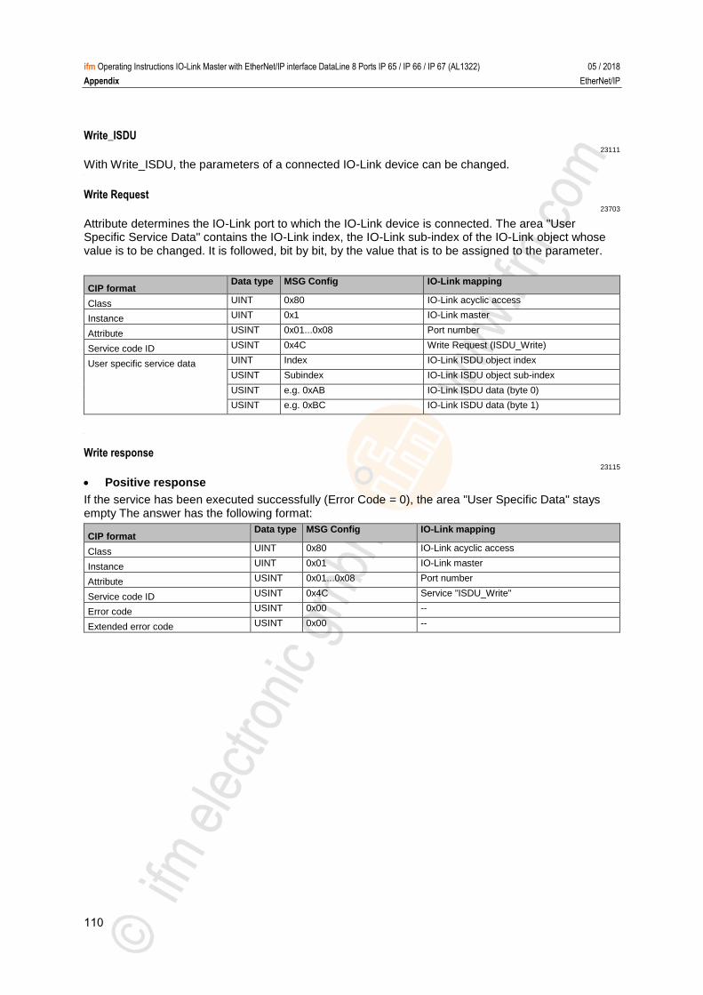
110
ifm Operating Instructions IO-Link Master with EtherNet/IP interface DataLine 8 Ports IP 65 / IP 66 / IP 67 (AL1322) 05 / 2018
Appendix EtherNet/IP
Write_ISDU 23111
With Write_ISDU, the parameters of a connected IO-Link device can be changed. >
Write Request 23703
Attribute determines the IO-Link port to which the IO-Link device is connected. The area "User Specific Service Data" contains the IO-Link index, the IO-Link sub-index of the IO-Link object whose value is to be changed. It is followed, bit by bit, by the value that is to be assigned to the parameter.
CIP format Data type MSG Config IO-Link mapping
Class UINT 0x80 IO-Link acyclic access
Instance UINT 0x1 IO-Link master
Attribute USINT 0x01...0x08 Port number
Service code ID USINT 0x4C Write Request (ISDU_Write)
User specific service data UINT Index IO-Link ISDU object index
USINT Subindex IO-Link ISDU object sub-index
USINT e.g. 0xAB IO-Link ISDU data (byte 0)
USINT e.g. 0xBC IO-Link ISDU data (byte 1)
>
Write response 23115
Positive response
If the service has been executed successfully (Error Code = 0), the area "User Specific Data" stays empty The answer has the following format:
CIP format Data type MSG Config IO-Link mapping
Class UINT 0x80 IO-Link acyclic access
Instance UINT 0x01 IO-Link master
Attribute USINT 0x01...0x08 Port number
Service code ID USINT 0x4C Service "ISDU_Write"
Error code USINT 0x00 --
Extended error code USINT 0x00 --
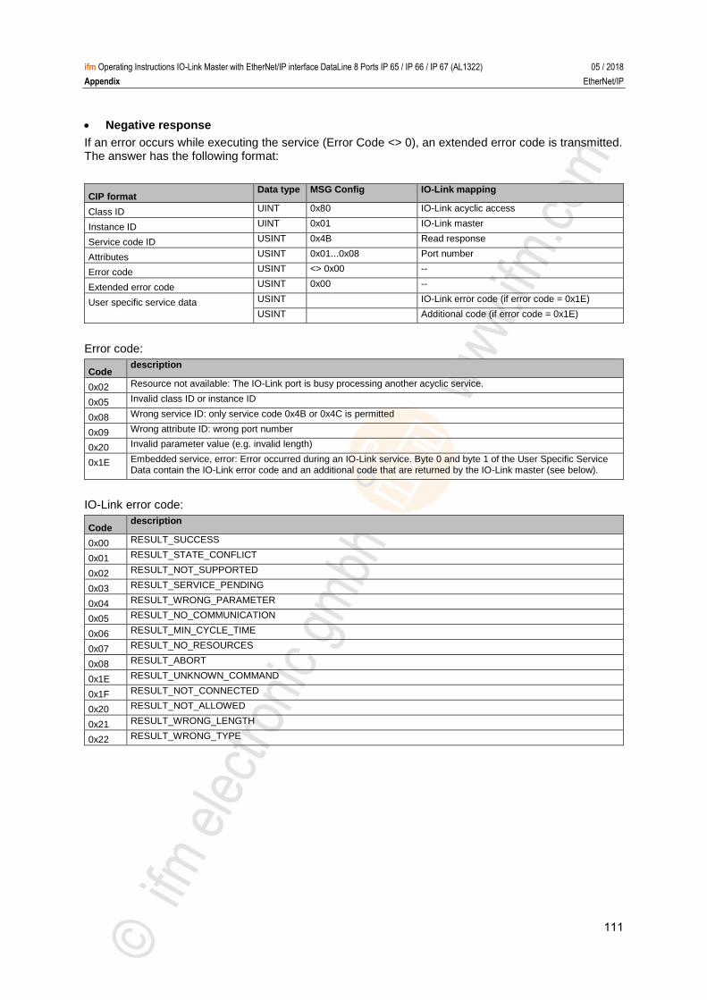
111
ifm Operating Instructions IO-Link Master with EtherNet/IP interface DataLine 8 Ports IP 65 / IP 66 / IP 67 (AL1322) 05 / 2018
Appendix EtherNet/IP
Negative response
If an error occurs while executing the service (Error Code <> 0), an extended error code is transmitted. The answer has the following format:
CIP format Data type MSG Config IO-Link mapping
Class ID UINT 0x80 IO-Link acyclic access
Instance ID UINT 0x01 IO-Link master
Service code ID USINT 0x4B Read response
Attributes USINT 0x01...0x08 Port number
Error code USINT <> 0x00 --
Extended error code USINT 0x00 --
User specific service data USINT IO-Link error code (if error code = 0x1E)
USINT Additional code (if error code = 0x1E)
Error code:
Code description
0x02 Resource not available: The IO-Link port is busy processing another acyclic service.
0x05 Invalid class ID or instance ID
0x08 Wrong service ID: only service code 0x4B or 0x4C is permitted
0x09 Wrong attribute ID: wrong port number
0x20 Invalid parameter value (e.g. invalid length)
0x1E Embedded service, error: Error occurred during an IO-Link service. Byte 0 and byte 1 of the User Specific Service Data contain the IO-Link error code and an additional code that are returned by the IO-Link master (see below).
IO-Link error code:
Code description
0x00 RESULT_SUCCESS
0x01 RESULT_STATE_CONFLICT
0x02 RESULT_NOT_SUPPORTED
0x03 RESULT_SERVICE_PENDING
0x04 RESULT_WRONG_PARAMETER
0x05 RESULT_NO_COMMUNICATION
0x06 RESULT_MIN_CYCLE_TIME
0x07 RESULT_NO_RESOURCES
0x08 RESULT_ABORT
0x1E RESULT_UNKNOWN_COMMAND
0x1F RESULT_NOT_CONNECTED
0x20 RESULT_NOT_ALLOWED
0x21 RESULT_WRONG_LENGTH
0x22 RESULT_WRONG_TYPE
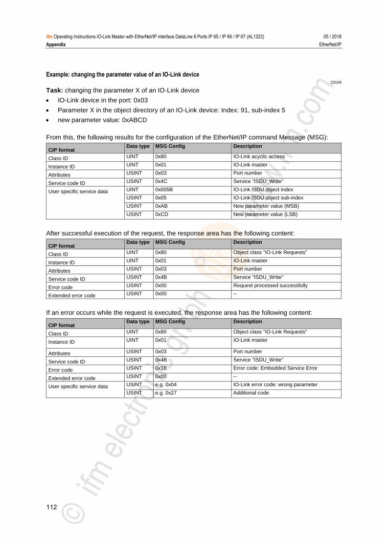
112
ifm Operating Instructions IO-Link Master with EtherNet/IP interface DataLine 8 Ports IP 65 / IP 66 / IP 67 (AL1322) 05 / 2018
Appendix EtherNet/IP
Example: changing the parameter value of an IO-Link device 23109
Task: changing the parameter X of an IO-Link device
IO-Link device in the port: 0x03
Parameter X in the object directory of an IO-Link device: Index: 91, sub-index 5
new parameter value: 0xABCD
From this, the following results for the configuration of the EtherNet/IP command Message (MSG):
CIP format Data type MSG Config Description
Class ID UINT 0x80 IO-Link acyclic access
Instance ID UINT 0x01 IO-Link master
Attributes USINT 0x03 Port number
Service code ID USINT 0x4C Service "ISDU_Write"
User specific service data UINT 0x005B IO-Link ISDU object index
USINT 0x05 IO-Link ISDU object sub-index
USINT 0xAB New parameter value (MSB)
USINT 0xCD New parameter value (LSB)
After successful execution of the request, the response area has the following content:
CIP format Data type MSG Config Description
Class ID UINT 0x80 Object class "IO-Link Requests"
Instance ID UINT 0x01 IO-Link master
Attributes USINT 0x03 Port number
Service code ID USINT 0x4B Service "ISDU_Write"
Error code USINT 0x00 Request processed successfully
Extended error code USINT 0x00 --
If an error occurs while the request is executed, the response area has the following content:
CIP format Data type MSG Config Description
Class ID UINT 0x80 Object class "IO-Link Requests"
Instance ID UINT 0x01 IO-Link master
Attributes USINT 0x03 Port number
Service code ID USINT 0x4B Service "ISDU_Write"
Error code USINT 0x1E Error code: Embedded Service Error
Extended error code USINT 0x00 --
User specific service data USINT e.g. 0x04 IO-Link error code: wrong parameter
USINT e.g. 0x27 Additional code
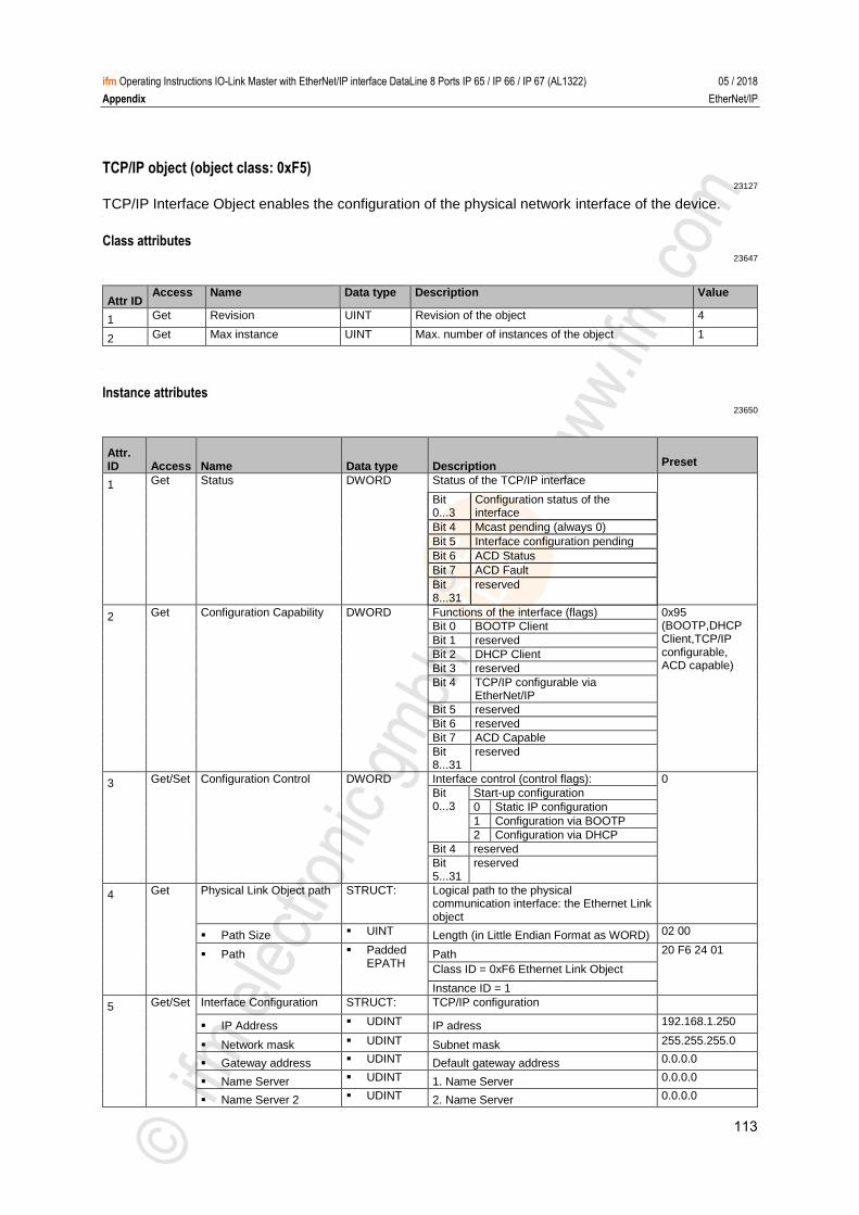
113
ifm Operating Instructions IO-Link Master with EtherNet/IP interface DataLine 8 Ports IP 65 / IP 66 / IP 67 (AL1322) 05 / 2018
Appendix EtherNet/IP
TCP/IP object (object class: 0xF5) 23127
TCP/IP Interface Object enables the configuration of the physical network interface of the device. >
Class attributes 23647
Attr ID Access Name Data type Description Value
1 Get Revision UINT Revision of the object 4
2 Get Max instance UINT Max. number of instances of the object 1
>
Instance attributes 23650
Attr. ID Access Name Data type Description Preset
1 Get Status DWORD Status of the TCP/IP interface
Bit 0...3
Configuration status of the interface
Bit 4 Mcast pending (always 0)
Bit 5 Interface configuration pending
Bit 6 ACD Status
Bit 7 ACD Fault
Bit 8...31
reserved
2 Get Configuration Capability DWORD Functions of the interface (flags) 0x95 (BOOTP,DHCP Client,TCP/IP configurable, ACD capable)
Bit 0 BOOTP Client
Bit 1 reserved
Bit 2 DHCP Client
Bit 3 reserved
Bit 4 TCP/IP configurable via EtherNet/IP
Bit 5 reserved
Bit 6 reserved
Bit 7 ACD Capable
Bit 8...31
reserved
3 Get/Set Configuration Control DWORD Interface control (control flags): 0
Bit 0...3
Start-up configuration
0 Static IP configuration
1 Configuration via BOOTP
2 Configuration via DHCP
Bit 4 reserved
Bit 5...31
reserved
4 Get Physical Link Object path STRUCT: Logical path to the physical communication interface: the Ethernet Link object
Path Size UINT Length (in Little Endian Format as WORD) 02 00
Path Padded EPATH
Path 20 F6 24 01
Class ID = 0xF6 Ethernet Link Object
Instance ID = 1
5 Get/Set Interface Configuration STRUCT: TCP/IP configuration
IP Address UDINT IP adress 192.168.1.250
Network mask UDINT Subnet mask 255.255.255.0
Gateway address UDINT Default gateway address 0.0.0.0
Name Server UDINT 1. Name Server 0.0.0.0
Name Server 2 UDINT 2. Name Server 0.0.0.0
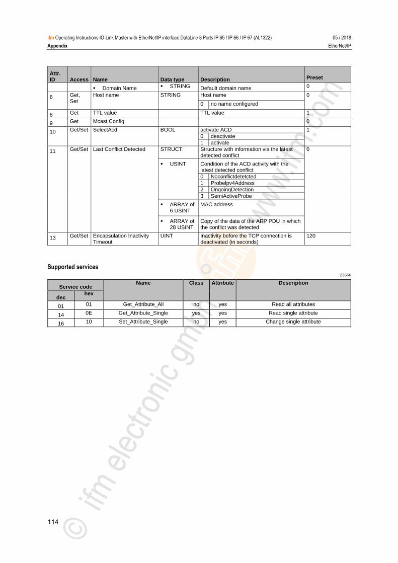
114
ifm Operating Instructions IO-Link Master with EtherNet/IP interface DataLine 8 Ports IP 65 / IP 66 / IP 67 (AL1322) 05 / 2018
Appendix EtherNet/IP
Attr. ID Access Name Data type Description Preset
Domain Name STRING Default domain name 0
6 Get, Set
Host name STRING Host name 0
0 no name configured
8 Get TTL value TTL value 1
9 Get Mcast Config 0
10 Get/Set SelectAcd BOOL activate ACD 1
0 deactivate
1 activate
11 Get/Set Last Conflict Detected STRUCT: Structure with information via the latest detected conflict
0
USINT Condition of the ACD activity with the latest detected conflict
0 Noconflictdetetcted
1 Probelpv4Address
2 OngoingDetection
3 SemiActiveProbe
ARRAY of 6 USINT
MAC address
ARRAY of 28 USINT
Copy of the data of the ARP PDU in which the conflict was detected
13 Get/Set Encapsulation Inactivity Timeout
UINT Inactivity before the TCP connection is deactivated (in seconds)
120
>
Supported services 23666
Service code Name Class Attribute Description
dec hex
01 01 Get_Attribute_All no yes Read all attributes
14 0E Get_Attribute_Single yes yes Read single attribute
16 10 Set_Attribute_Single no yes Change single attribute >
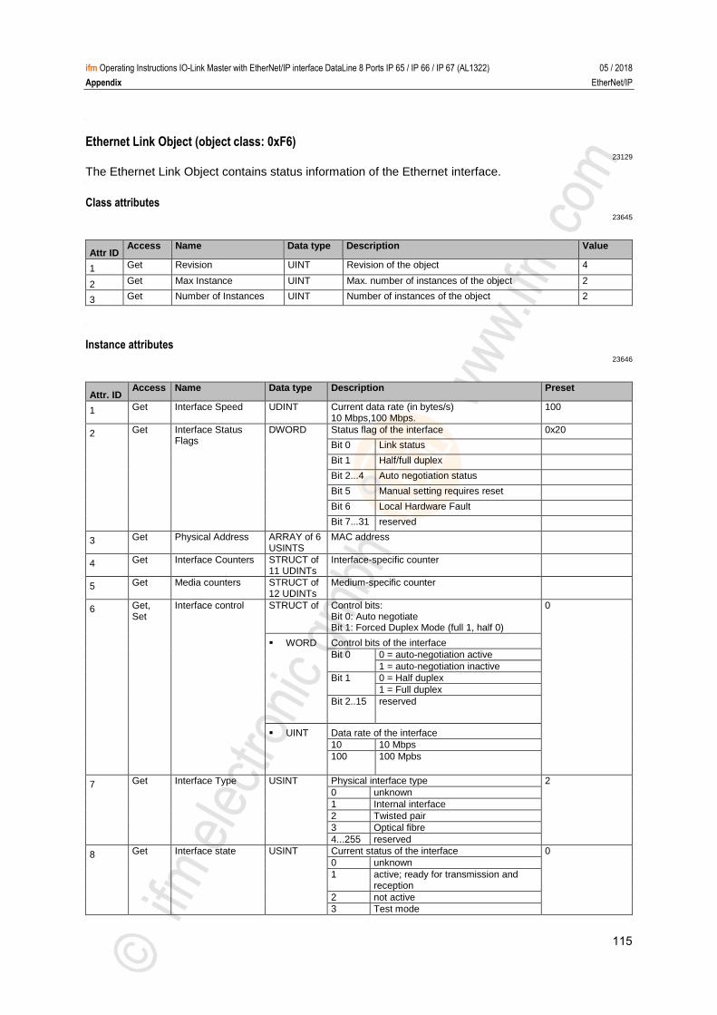
115
ifm Operating Instructions IO-Link Master with EtherNet/IP interface DataLine 8 Ports IP 65 / IP 66 / IP 67 (AL1322) 05 / 2018
Appendix EtherNet/IP
>
Ethernet Link Object (object class: 0xF6) 23129
The Ethernet Link Object contains status information of the Ethernet interface. >
Class attributes 23645
Attr ID Access Name Data type Description Value
1 Get Revision UINT Revision of the object 4
2 Get Max Instance UINT Max. number of instances of the object 2
3 Get Number of Instances UINT Number of instances of the object 2
>
Instance attributes 23646
Attr. ID Access Name Data type Description Preset
1 Get Interface Speed UDINT Current data rate (in bytes/s) 10 Mbps,100 Mbps.
100
2 Get Interface Status Flags
DWORD Status flag of the interface 0x20
Bit 0 Link status
Bit 1 Half/full duplex
Bit 2...4 Auto negotiation status
Bit 5 Manual setting requires reset
Bit 6 Local Hardware Fault
Bit 7...31 reserved
3 Get Physical Address ARRAY of 6 USINTS
MAC address
4 Get Interface Counters STRUCT of 11 UDINTs
Interface-specific counter
5 Get Media counters STRUCT of 12 UDINTs
Medium-specific counter
6 Get, Set
Interface control STRUCT of Control bits: Bit 0: Auto negotiate Bit 1: Forced Duplex Mode (full 1, half 0)
0
WORD Control bits of the interface
Bit 0 0 = auto-negotiation active
1 = auto-negotiation inactive
Bit 1 0 = Half duplex
1 = Full duplex
Bit 2..15 reserved
UINT Data rate of the interface
10 10 Mbps
100 100 Mpbs
7 Get Interface Type USINT Physical interface type 2
0 unknown
1 Internal interface
2 Twisted pair
3 Optical fibre
4...255 reserved
8 Get Interface state USINT Current status of the interface 0
0 unknown
1 active; ready for transmission and reception
2 not active
3 Test mode
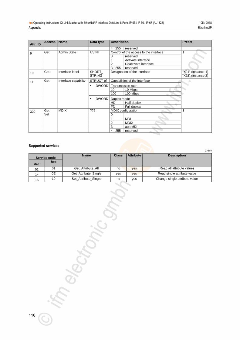
116
ifm Operating Instructions IO-Link Master with EtherNet/IP interface DataLine 8 Ports IP 65 / IP 66 / IP 67 (AL1322) 05 / 2018
Appendix EtherNet/IP
Attr. ID Access Name Data type Description Preset
4...255 reserved
9 Get Admin State USINT Control of the access to the interface 1
0 reserved
1 Activate interface
2 Deactivate interface
3...255 reserved
10 Get Interface label SHORT_ STRING
Designation of the interface "X21" (instance 1) "X22" (instance 2)
11 Get Interface capability STRUCT of Capabilities of the interface
DWORD Transmission rate
10 10 Mbps
100 100 Mbps
DWORD Duplex mode
HD Half duplex
FD Full duplex
300 Get, Set
MDIX ??? MDIX configuration 3
0
1 MDI
2 MDIX
3 autoMDI
4...255 reserved
>
Supported services 23665
Service code Name Class Attribute Description
dec hex
01 01 Get_Attribute_All no yes Read all attribute values
14 0E Get_Attribute_Single yes yes Read single attribute value
16 10 Set_Attribute_Single no yes Change single attribute value >

117
ifm Operating Instructions IO-Link Master with EtherNet/IP interface DataLine 8 Ports IP 65 / IP 66 / IP 67 (AL1322) 05 / 2018
Appendix ifm IoT Core
13.3 ifm IoT Core
Overview: IoT profile.......................................................................................................................... 118 Overview: IoT types ........................................................................................................................... 121 Overview: IoT services ...................................................................................................................... 122
8988
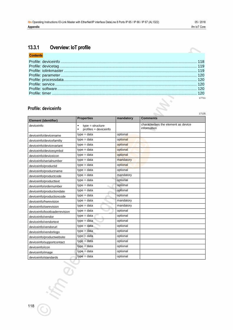
118
ifm Operating Instructions IO-Link Master with EtherNet/IP interface DataLine 8 Ports IP 65 / IP 66 / IP 67 (AL1322) 05 / 2018
Appendix ifm IoT Core
13.3.1 Overview: IoT profile
Profile: deviceinfo .............................................................................................................................. 118 Profile: devicetag ............................................................................................................................... 119 Profile: iolinkmaster ........................................................................................................................... 119 Profile: parameter .............................................................................................................................. 120 Profile: processdata ........................................................................................................................... 120 Profile: service ................................................................................................................................... 120 Profile: software ................................................................................................................................. 120 Profile: timer ...................................................................................................................................... 120
17711 >
Profile: deviceinfo 17135
Element (identifier) Properties mandatory Comments
deviceinfo type = structure profiles = deviceinfo
characterises the element as device information
deviceinfo/devicename type = data optional
deviceinfo/devicefamiliy type = data optional
deviceinfo/devicevariant type = data optional
deviceinfo/devicesymbol type = data optional
deviceinfo/deviceicon type = data optional
deviceinfo/serialnumber type = data mandatory
deviceinfo/productid type = data optional
deviceinfo/productname type = data optional
deviceinfo/productcode type = data mandatory
deviceinfo/producttext type = data optional
deviceinfo/ordernumber type = data optional
deviceinfo/productiondate type = data optional
deviceinfo/productioncode type = data optional
deviceinfo/hwrevision type = data mandatory
deviceinfo/swrevision type = data mandatory
deviceinfo/bootloaderrevision type = data optional
deviceinfo/vendor type = data optional
deviceinfo/vendortext type = data optional
deviceinfo/vendorurl type = data optional
deviceinfo/vendorlogo type = data optional
deviceinfo/productwebsite type = data optional
deviceinfo/supportcontact type = data optional
deviceinfo/icon type = data optional
deviceinfo/image type = data optional
deviceinfo/standards type = data optional
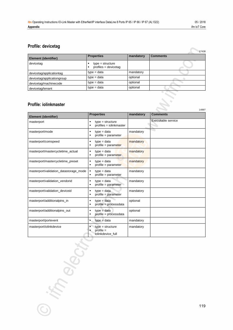
119
ifm Operating Instructions IO-Link Master with EtherNet/IP interface DataLine 8 Ports IP 65 / IP 66 / IP 67 (AL1322) 05 / 2018
Appendix ifm IoT Core
Profile: devicetag 17438
Element (identifier) Properties mandatory Comments
devicetag type = structure profiles = devicetag
devicetag/applicationtag type = data mandatory
devicetag/applicationgroup type = data optional
devicetag/machinecode type = data optional
devicetag/tenant type = data optional
>
Profile: iolinkmaster 14997
Element (identifier) Properties mandatory Comments
masterport type = structure profiles = iolinkmaster
Executable service
masterport/mode type = data profile = parameter
mandatory
masterport/comspeed type = data profile = parameter
mandatory
masterport/mastercycletime_actual type = data profile = parameter
mandatory
masterport/mastercycletime_preset type = data profile = parameter
mandatory
masterport/validation_datastorage_mode type = data profile = parameter
mandatory
masterport/validation_vendorid type = data profile = parameter
mandatory
masterport/validation_deviceid type = data profile = parameter
mandatory
masterport/additionalpins_in type = data profile = processdata
optional
masterport/additionalpins_out type = data profile = processdata
optional
masterport/portevent type = data mandatory
masterport/iolinkdevice type = structure profile =
iolinkdevice_full
mandatory
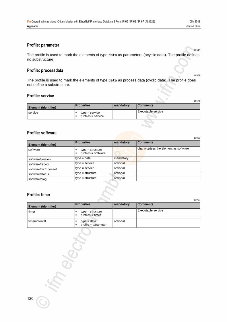
120
ifm Operating Instructions IO-Link Master with EtherNet/IP interface DataLine 8 Ports IP 65 / IP 66 / IP 67 (AL1322) 05 / 2018
Appendix ifm IoT Core
Profile: parameter 16545
The profile is used to mark the elements of type data as parameters (acyclic data). The profile defines
no substructure. >
Profile: processdata 16569
The profile is used to mark the elements of type data as process data (cyclic data). The profile does
not define a substructure. >
Profile: service 16575
Element (identifier) Properties mandatory Comments
service type = service profiles = service
Executable service
>
Profile: software 10999
Element (identifier) Properties mandatory Comments
software type = structure profiles = software
characterises the element as software
software/version type = data mandatory
software/reboot type = service optional
software/factoryreset type = service optional
software/status type = structure optional
software/diag type = structure optional
>
Profile: timer 10997
Element (identifier) Properties mandatory Comments
timer type = structure profiles = timer
Executable service
timer/interval type = data profile = parameter
optional

121
ifm Operating Instructions IO-Link Master with EtherNet/IP interface DataLine 8 Ports IP 65 / IP 66 / IP 67 (AL1322) 05 / 2018
Appendix ifm IoT Core
13.3.2 Overview: IoT types 16547
The ifm IoT Core uses the following element types:
Name Description
structure Element is a structure element (like a folder in a file system)
service Element is a service that can be addressed from the network
event Element is an event that can be started by the firmware and sends messages.
data Element is a data point
device Root element a device represents
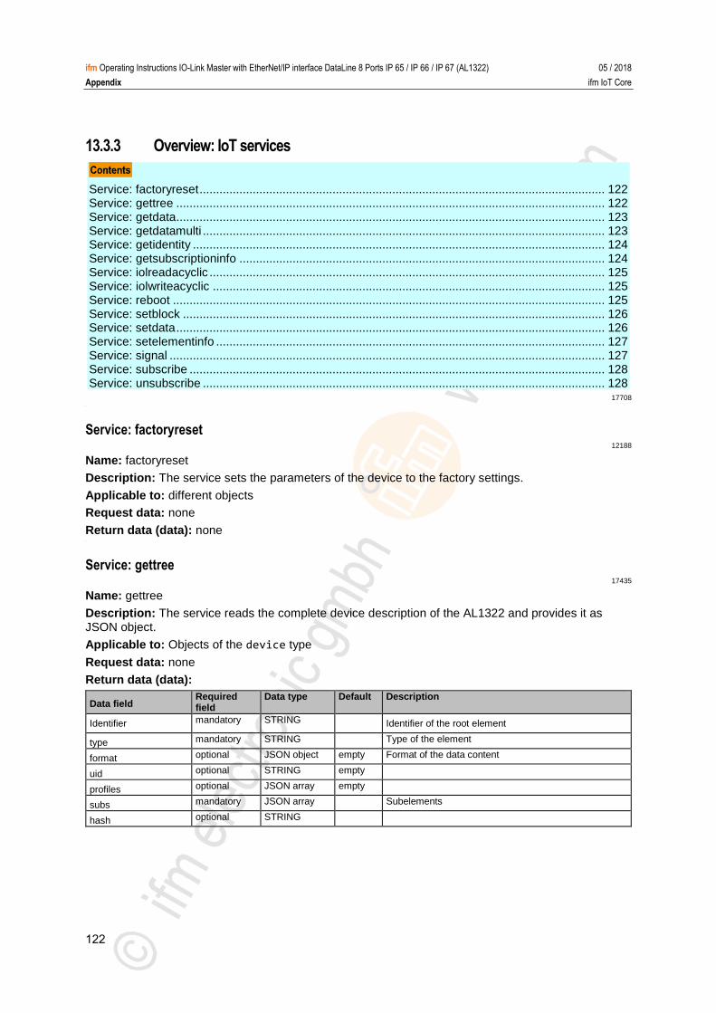
122
ifm Operating Instructions IO-Link Master with EtherNet/IP interface DataLine 8 Ports IP 65 / IP 66 / IP 67 (AL1322) 05 / 2018
Appendix ifm IoT Core
13.3.3 Overview: IoT services
Service: factoryreset .......................................................................................................................... 122 Service: gettree ................................................................................................................................. 122 Service: getdata ................................................................................................................................. 123 Service: getdatamulti ......................................................................................................................... 123 Service: getidentity ............................................................................................................................ 124 Service: getsubscriptioninfo .............................................................................................................. 124 Service: iolreadacyclic ....................................................................................................................... 125 Service: iolwriteacyclic ...................................................................................................................... 125 Service: reboot .................................................................................................................................. 125 Service: setblock ............................................................................................................................... 126 Service: setdata ................................................................................................................................. 126 Service: setelementinfo ..................................................................................................................... 127 Service: signal ................................................................................................................................... 127 Service: subscribe ............................................................................................................................. 128 Service: unsubscribe ......................................................................................................................... 128
17708 >
Service: factoryreset 12188
Name: factoryreset
Description: The service sets the parameters of the device to the factory settings.
Applicable to: different objects
Request data: none
Return data (data): none >
Service: gettree 17435
Name: gettree
Description: The service reads the complete device description of the AL1322 and provides it as JSON object.
Applicable to: Objects of the device type
Request data: none
Return data (data):
Data field Required field
Data type Default Description
Identifier mandatory STRING Identifier of the root element
type mandatory STRING Type of the element
format optional JSON object empty Format of the data content
uid optional STRING empty
profiles optional JSON array empty
subs mandatory JSON array Subelements
hash optional STRING
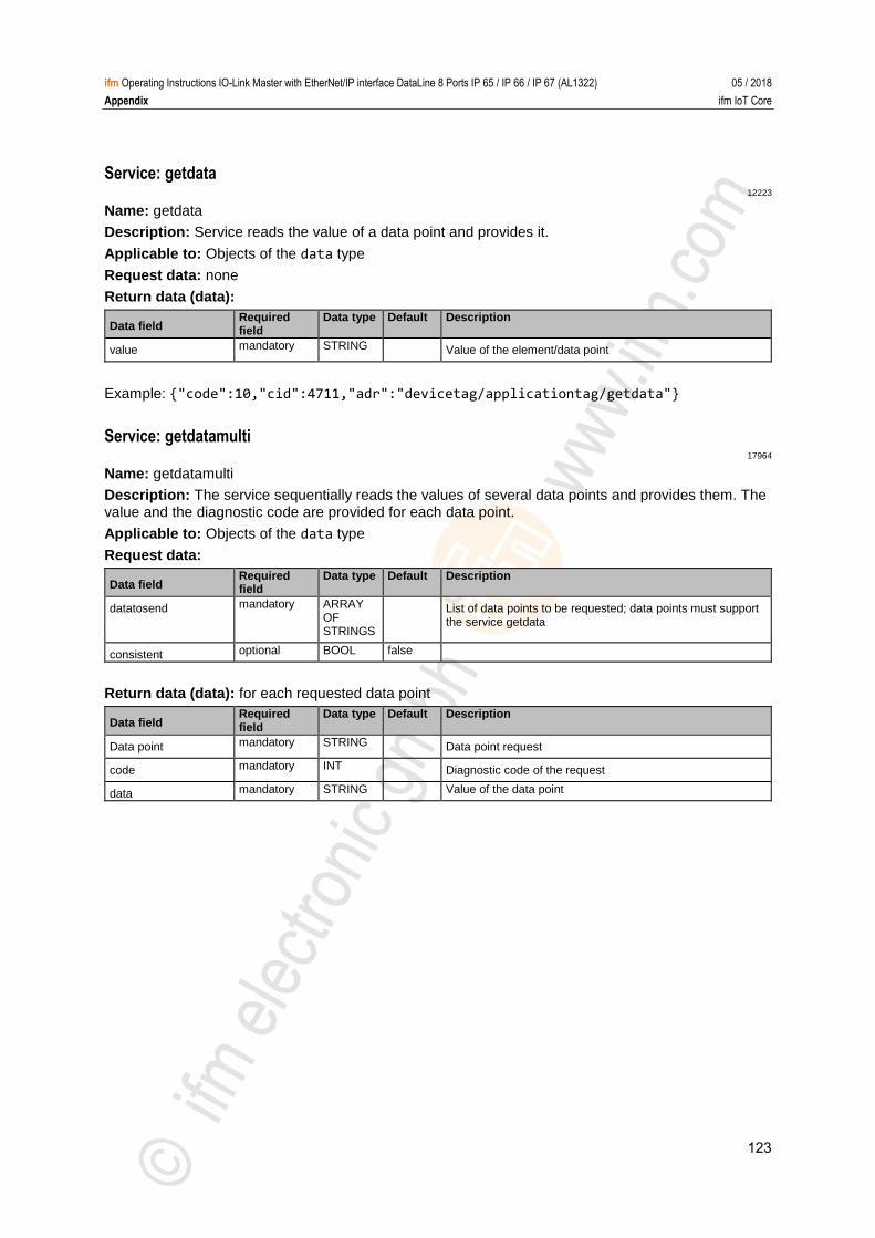
123
ifm Operating Instructions IO-Link Master with EtherNet/IP interface DataLine 8 Ports IP 65 / IP 66 / IP 67 (AL1322) 05 / 2018
Appendix ifm IoT Core
Service: getdata 12223
Name: getdata
Description: Service reads the value of a data point and provides it.
Applicable to: Objects of the data type
Request data: none
Return data (data):
Data field Required field
Data type Default Description
value mandatory STRING Value of the element/data point
Example: {"code":10,"cid":4711,"adr":"devicetag/applicationtag/getdata"} >
Service: getdatamulti 17964
Name: getdatamulti
Description: The service sequentially reads the values of several data points and provides them. The value and the diagnostic code are provided for each data point.
Applicable to: Objects of the data type
Request data:
Data field Required field
Data type Default Description
datatosend mandatory ARRAY OF STRINGS
List of data points to be requested; data points must support the service getdata
consistent optional BOOL false
Return data (data): for each requested data point
Data field Required field
Data type Default Description
Data point mandatory STRING Data point request
code mandatory INT Diagnostic code of the request
data mandatory STRING Value of the data point
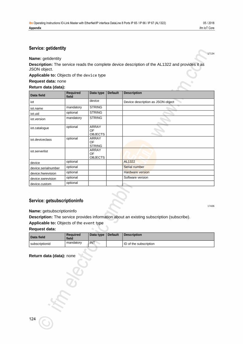
124
ifm Operating Instructions IO-Link Master with EtherNet/IP interface DataLine 8 Ports IP 65 / IP 66 / IP 67 (AL1322) 05 / 2018
Appendix ifm IoT Core
Service: getidentity 17134
Name: getidentity
Description: The service reads the complete device description of the AL1322 and provides it as JSON object.
Applicable to: Objects of the device type
Request data: none
Return data (data):
Data field Required field
Data type Default Description
iot device Device description as JSON object
iot.name mandatory STRING
iot.uid optional STRING
iot.version mandatory STRING
iot.catalogue optional ARRAY OF OBJECTS
iot.deviceclass optional ARRAY OF STRING
iot.serverlist ARRAY OF OBJECTS
device optional AL1322
device.serialnumber optional Serial number
device.hwrevision optional Hardware version
device.swrevision optional Software version
device.custom optional
>
Service: getsubscriptioninfo 17436
Name: getsubscriptioninfo
Description: The service provides information about an existing subscription (subscribe).
Applicable to: Objects of the event type
Request data:
Data field Required field
Data type Default Description
subscriptionid mandatory INT ID of the subscription
Return data (data): none
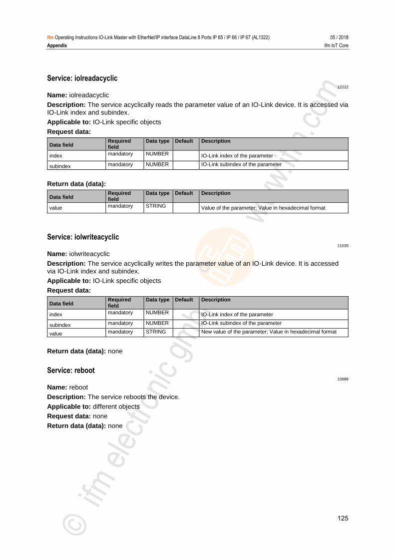
125
ifm Operating Instructions IO-Link Master with EtherNet/IP interface DataLine 8 Ports IP 65 / IP 66 / IP 67 (AL1322) 05 / 2018
Appendix ifm IoT Core
Service: iolreadacyclic 12222
Name: iolreadacyclic
Description: The service acyclically reads the parameter value of an IO-Link device. It is accessed via IO-Link index and subindex.
Applicable to: IO-Link specific objects
Request data:
Data field Required field
Data type Default Description
index mandatory NUMBER IO-Link index of the parameter
subindex mandatory NUMBER IO-Link subindex of the parameter
Return data (data):
Data field Required field
Data type Default Description
value mandatory STRING Value of the parameter; Value in hexadecimal format
>
Service: iolwriteacyclic 11035
Name: iolwriteacyclic
Description: The service acyclically writes the parameter value of an IO-Link device. It is accessed via IO-Link index and subindex.
Applicable to: IO-Link specific objects
Request data:
Data field Required field
Data type Default Description
index mandatory NUMBER IO-Link index of the parameter
subindex mandatory NUMBER IO-Link subindex of the parameter
value mandatory STRING New value of the parameter; Value in hexadecimal format
Return data (data): none >
Service: reboot 10986
Name: reboot
Description: The service reboots the device.
Applicable to: different objects
Request data: none
Return data (data): none
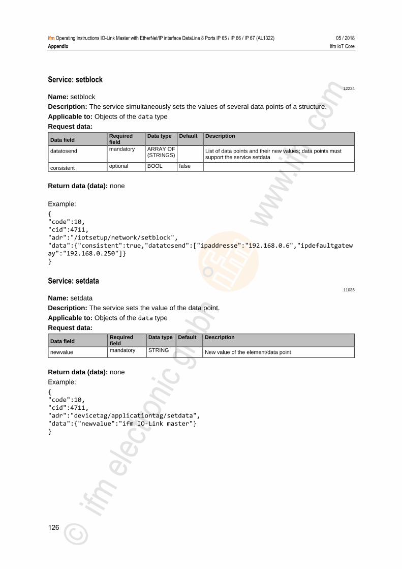
126
ifm Operating Instructions IO-Link Master with EtherNet/IP interface DataLine 8 Ports IP 65 / IP 66 / IP 67 (AL1322) 05 / 2018
Appendix ifm IoT Core
Service: setblock 12224
Name: setblock
Description: The service simultaneously sets the values of several data points of a structure.
Applicable to: Objects of the data type
Request data:
Data field Required field
Data type Default Description
datatosend mandatory ARRAY OF (STRINGS)
List of data points and their new values; data points must support the service setdata
consistent optional BOOL false
Return data (data): none
Example:
{
"code":10, "cid":4711,
"adr":"/iotsetup/network/setblock",
"data":{"consistent":true,"datatosend":["ipaddresse":"192.168.0.6","ipdefaultgateway":"192.168.0.250"]}
} >
Service: setdata 11036
Name: setdata
Description: The service sets the value of the data point.
Applicable to: Objects of the data type
Request data:
Data field Required field
Data type Default Description
newvalue mandatory STRING New value of the element/data point
Return data (data): none
Example:
{ "code":10,
"cid":4711, "adr":"devicetag/applicationtag/setdata",
"data":{"newvalue":"ifm IO-Link master"}
}
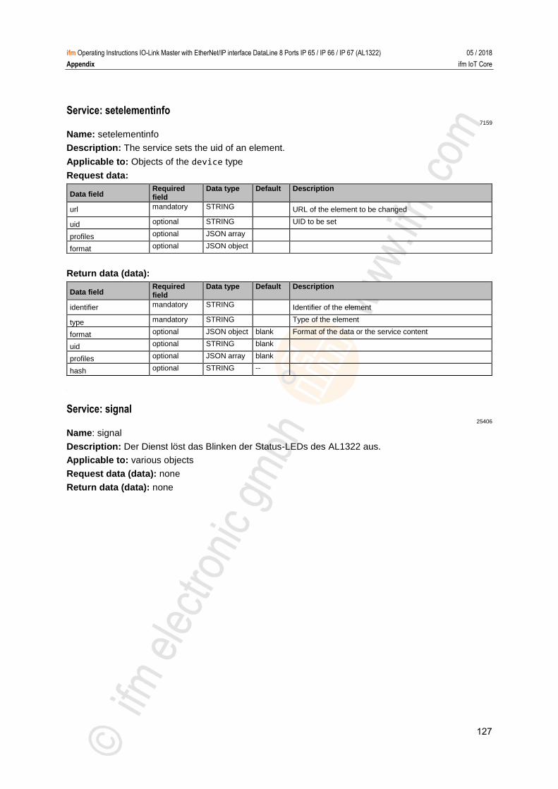
127
ifm Operating Instructions IO-Link Master with EtherNet/IP interface DataLine 8 Ports IP 65 / IP 66 / IP 67 (AL1322) 05 / 2018
Appendix ifm IoT Core
Service: setelementinfo 7159
Name: setelementinfo
Description: The service sets the uid of an element.
Applicable to: Objects of the device type
Request data:
Data field Required field
Data type Default Description
url mandatory STRING URL of the element to be changed
uid optional STRING UID to be set
profiles optional JSON array
format optional JSON object
Return data (data):
Data field Required field
Data type Default Description
identifier mandatory STRING Identifier of the element
type mandatory STRING Type of the element
format optional JSON object blank Format of the data or the service content
uid optional STRING blank
profiles optional JSON array blank
hash optional STRING --
>
Service: signal 25406
Name: signal
Description: Der Dienst löst das Blinken der Status-LEDs des AL1322 aus.
Applicable to: various objects
Request data (data): none
Return data (data): none
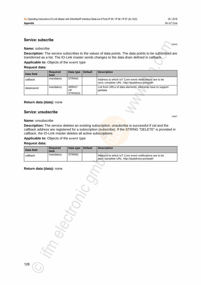
128
ifm Operating Instructions IO-Link Master with EtherNet/IP interface DataLine 8 Ports IP 65 / IP 66 / IP 67 (AL1322) 05 / 2018
Appendix ifm IoT Core
Service: subscribe 10920
Name: subscribe
Description: The service subscribes to the values of data points. The data points to be subscribed are transferred as a list. The IO-Link master sends changes to the data drain defined in callback.
Applicable to: Objects of the event type
Request data:
Data field Required field
Data type Default Description
callback mandatory STRING Address to which IoT Core event notifications are to be sent; complete URL: http://ipaddress:port/path
datatosend mandatory ARRAY OF STRINGS
List from URLs of data elements; elements have to support getdata
Return data (data): none >
Service: unsubscribe 16567
Name: unsubscribe
Description: The service deletes an existing subscription. unsubcribe is successful if cid and the callback address are registered for a subscription (subscribe). If the STRING "DELETE" is provided in callback, the IO-Link master deletes all active subscriptions.
Applicable to: Objects of the event type
Request data:
Data field Required field
Data type Default Description
callback mandatory STRING Address to which IoT Core event notifications are to be sent; complete URL: http://ipaddress:port/path
Return data (data): none
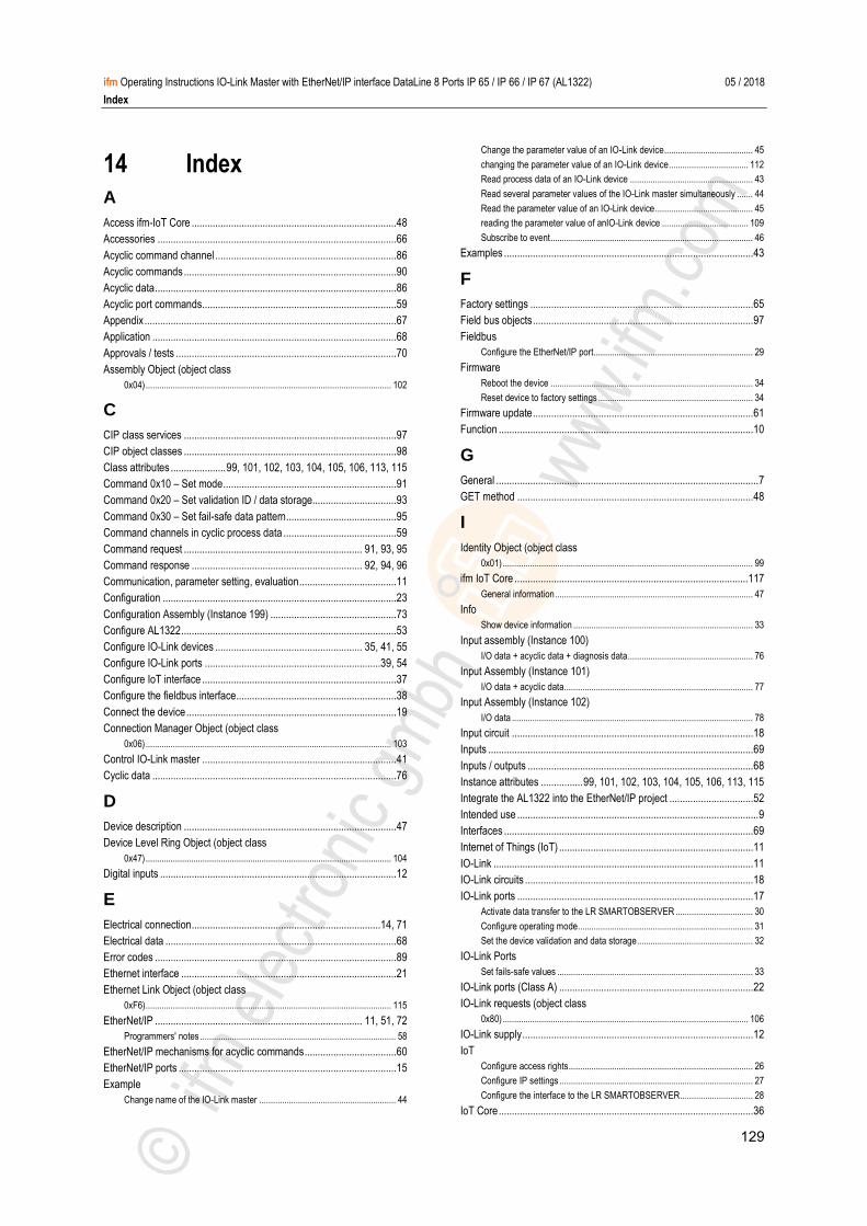
129
ifm Operating Instructions IO-Link Master with EtherNet/IP interface DataLine 8 Ports IP 65 / IP 66 / IP 67 (AL1322) 05 / 2018
Index
14 Index
A
Access ifm-IoT Core .............................................................................. 48
Accessories ........................................................................................... 66
Acyclic command channel ..................................................................... 86
Acyclic commands ................................................................................. 90
Acyclic data ............................................................................................ 86
Acyclic port commands .......................................................................... 59
Appendix ................................................................................................ 67
Application ............................................................................................. 68
Approvals / tests .................................................................................... 70
Assembly Object (object class
0x04) ............................................................................................................ 102
C
CIP class services ................................................................................. 97
CIP object classes ................................................................................. 98
Class attributes ..................... 99, 101, 102, 103, 104, 105, 106, 113, 115
Command 0x10 – Set mode .................................................................. 91
Command 0x20 – Set validation ID / data storage................................ 93
Command 0x30 – Set fail-safe data pattern .......................................... 95
Command channels in cyclic process data ........................................... 59
Command request .................................................................... 91, 93, 95
Command response ................................................................. 92, 94, 96
Communication, parameter setting, evaluation ..................................... 11
Configuration ......................................................................................... 23
Configuration Assembly (Instance 199) ................................................ 73
Configure AL1322 .................................................................................. 53
Configure IO-Link devices ........................................................ 35, 41, 55
Configure IO-Link ports ...................................................................39, 54
Configure IoT interface .......................................................................... 37
Configure the fieldbus interface ............................................................. 38
Connect the device ................................................................................ 19
Connection Manager Object (object class
0x06) ............................................................................................................ 103
Control IO-Link master .......................................................................... 41
Cyclic data ............................................................................................. 76
D
Device description ................................................................................. 47
Device Level Ring Object (object class
0x47) ............................................................................................................ 104
Digital inputs .......................................................................................... 12
E
Electrical connection ........................................................................14, 71
Electrical data ........................................................................................ 68
Error codes ............................................................................................ 89
Ethernet interface .................................................................................. 21
Ethernet Link Object (object class
0xF6) ............................................................................................................ 115
EtherNet/IP ............................................................................... 11, 51, 72
Programmers' notes ...................................................................................... 58
EtherNet/IP mechanisms for acyclic commands ................................... 60
EtherNet/IP ports ................................................................................... 15
Example
Change name of the IO-Link master ............................................................ 44
Change the parameter value of an IO-Link device ....................................... 45
changing the parameter value of an IO-Link device ................................... 112
Read process data of an IO-Link device ...................................................... 43
Read several parameter values of the IO-Link master simultaneously ....... 44
Read the parameter value of an IO-Link device ........................................... 45
reading the parameter value of anIO-Link device ...................................... 109
Subscribe to event ......................................................................................... 46
Examples ............................................................................................... 43
F
Factory settings ..................................................................................... 65
Field bus objects .................................................................................... 97
Fieldbus
Configure the EtherNet/IP port...................................................................... 29
Firmware
Reboot the device ......................................................................................... 34
Reset device to factory settings .................................................................... 34
Firmware update .................................................................................... 61
Function ................................................................................................. 10
G
General .................................................................................................... 7
GET method .......................................................................................... 48
I
Identity Object (object class
0x01) .............................................................................................................. 99
ifm IoT Core ......................................................................................... 117
General information ....................................................................................... 47
Info
Show device information ............................................................................... 33
Input assembly (Instance 100)
I/O data + acyclic data + diagnosis data ....................................................... 76
Input Assembly (Instance 101)
I/O data + acyclic data................................................................................... 77
Input Assembly (Instance 102)
I/O data .......................................................................................................... 78
Input circuit ............................................................................................ 18
Inputs ..................................................................................................... 69
Inputs / outputs ...................................................................................... 68
Instance attributes ................ 99, 101, 102, 103, 104, 105, 106, 113, 115
Integrate the AL1322 into the EtherNet/IP project ................................ 52
Intended use ............................................................................................ 9
Interfaces ............................................................................................... 69
Internet of Things (IoT) .......................................................................... 11
IO-Link ................................................................................................... 11
IO-Link circuits ....................................................................................... 18
IO-Link ports .......................................................................................... 17
Activate data transfer to the LR SMARTOBSERVER .................................. 30
Configure operating mode............................................................................. 31
Set the device validation and data storage................................................... 32
IO-Link Ports
Set fails-safe values ...................................................................................... 33
IO-Link ports (Class A) .......................................................................... 22
IO-Link requests (object class
0x80) ............................................................................................................ 106
IO-Link supply ........................................................................................ 12
IoT
Configure access rights ................................................................................. 26
Configure IP settings ..................................................................................... 27
Configure the interface to the LR SMARTOBSERVER................................ 28
IoT Core ................................................................................................. 36
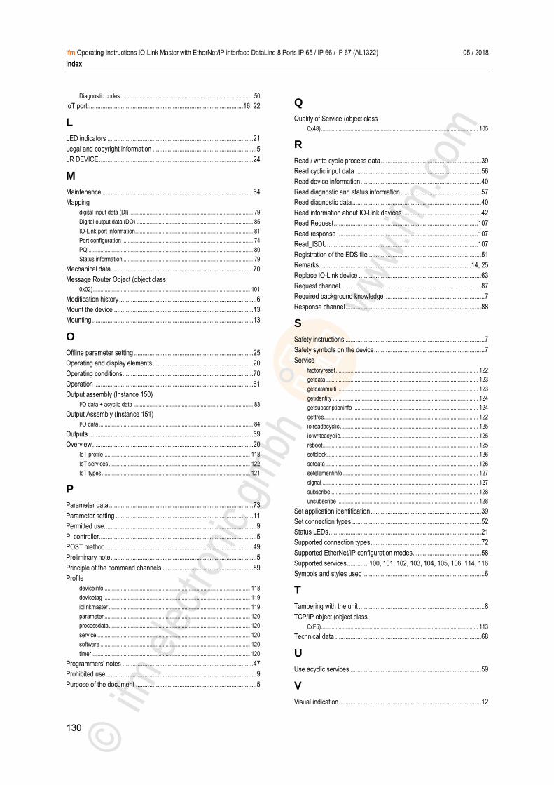
130
ifm Operating Instructions IO-Link Master with EtherNet/IP interface DataLine 8 Ports IP 65 / IP 66 / IP 67 (AL1322) 05 / 2018
Index
Diagnostic codes ........................................................................................... 50
IoT port .............................................................................................16, 22
L
LED indicators ....................................................................................... 21
Legal and copyright information .............................................................. 5
LR DEVICE ............................................................................................ 24
M
Maintenance .......................................................................................... 64
Mapping
digital input data (DI) ..................................................................................... 79
Digital output data (DO) ................................................................................ 85
IO-Link port information................................................................................. 81
Port configuration .......................................................................................... 74
PQI ................................................................................................................. 80
Status information ......................................................................................... 79
Mechanical data ..................................................................................... 70
Message Router Object (object class
0x02) ............................................................................................................ 101
Modification history .................................................................................. 6
Mount the device ................................................................................... 13
Mounting ................................................................................................ 13
O
Offline parameter setting ....................................................................... 25
Operating and display elements ............................................................ 20
Operating conditions .............................................................................. 70
Operation ............................................................................................... 61
Output assembly (Instance 150)
I/O data + acyclic data .................................................................................. 83
Output Assembly (Instance 151)
I/O data .......................................................................................................... 84
Outputs .................................................................................................. 69
Overview ................................................................................................ 20
IoT profile ..................................................................................................... 118
IoT services ................................................................................................. 122
IoT types ...................................................................................................... 121
P
Parameter data ...................................................................................... 73
Parameter setting .................................................................................. 11
Permitted use ........................................................................................... 9
PI controller .............................................................................................. 5
POST method ........................................................................................ 49
Preliminary note ....................................................................................... 5
Principle of the command channels ...................................................... 59
Profile
deviceinfo .................................................................................................... 118
devicetag ..................................................................................................... 119
iolinkmaster ................................................................................................. 119
parameter .................................................................................................... 120
processdata ................................................................................................. 120
service ......................................................................................................... 120
software ....................................................................................................... 120
timer ............................................................................................................. 120
Programmers' notes .............................................................................. 47
Prohibited use .......................................................................................... 9
Purpose of the document ........................................................................ 5
Q
Quality of Service (object class
0x48) ............................................................................................................ 105
R
Read / write cyclic process data ............................................................ 39
Read cyclic input data ........................................................................... 56
Read device information ........................................................................ 40
Read diagnostic and status information ................................................ 57
Read diagnostic data ............................................................................. 40
Read information about IO-Link devices ............................................... 42
Read Request ...................................................................................... 107
Read response .................................................................................... 107
Read_ISDU .......................................................................................... 107
Registration of the EDS file ................................................................... 51
Remarks...........................................................................................14, 25
Replace IO-Link device ......................................................................... 63
Request channel .................................................................................... 87
Required background knowledge ............................................................ 7
Response channel ................................................................................. 88
S
Safety instructions ................................................................................... 7
Safety symbols on the device .................................................................. 7
Service
factoryreset .................................................................................................. 122
getdata ......................................................................................................... 123
getdatamulti ................................................................................................. 123
getidentity .................................................................................................... 124
getsubscriptioninfo ...................................................................................... 124
gettree .......................................................................................................... 122
iolreadacyclic ............................................................................................... 125
iolwriteacyclic ............................................................................................... 125
reboot ........................................................................................................... 125
setblock........................................................................................................ 126
setdata ......................................................................................................... 126
setelementinfo ............................................................................................. 127
signal ........................................................................................................... 127
subscribe ..................................................................................................... 128
unsubscribe ................................................................................................. 128
Set application identification .................................................................. 39
Set connection types ............................................................................. 52
Status LEDs ........................................................................................... 21
Supported connection types .................................................................. 72
Supported EtherNet/IP configuration modes ......................................... 58
Supported services ............. 100, 101, 102, 103, 104, 105, 106, 114, 116
Symbols and styles used ......................................................................... 6
T
Tampering with the unit ........................................................................... 8
TCP/IP object (object class
0xF5) ............................................................................................................ 113
Technical data ....................................................................................... 68
U
Use acyclic services .............................................................................. 59
V
Visual indication ..................................................................................... 12

131
ifm Operating Instructions IO-Link Master with EtherNet/IP interface DataLine 8 Ports IP 65 / IP 66 / IP 67 (AL1322) 05 / 2018
Index
Voltage supply ....................................................................................... 22
VPN connection ..................................................................................... 25
W
Web interface
Read device and diagnostic information....................................................... 62
Write cyclic output data ......................................................................... 56
Write Request ...................................................................................... 110
Write response ..................................................................................... 110
Write_ISDU .......................................................................................... 110