io-link master 8 ports ip20 ethernet/ip ay1020 operators ...file/ay1020... · io-link master 8...
TRANSCRIPT
IO-Link Master 8
Ports IP20
Ethernet/IP AY1020
Operators Manual

Trademark Notices
Other product names mentioned herein may be trademarks and/or registered trademarks of their respective owners.
First Edition, May 6, 2015 Copyright © 2015. ifm electronic gmbh. All Rights Reserved.
ifm electronic gmbh makes no representations or warranties with regard to the contents of this document or to the suitability of the ifm product for any particular purpose. Specifications subject to change without notice. Some software or features may not be available at the time of publication. Contact your reseller for current product information.
AY1020 Operators Manual: Rev. A Table of Contents - 3
Table of Contents
Chapter 1. Introduction ............................................................................................................................... 9
1.1. Installation and Configuration Overview .................................................................................................................. 9
Chapter 2. Hardware Installation ............................................................................................................ 11 2.1. Connecting to the Network .......................................................................................................................................... 11 2.2. Connecting the Power .................................................................................................................................................. 11
Chapter 3. Initial Configuration ............................................................................................................... 13 3.1. Using the Web Interface to Program the Network ................................................................................................ 13 3.2. Setting User Accounts and Passwords ..................................................................................................................... 15 3.3. Configuring Miscellaneous Settings ........................................................................................................................ 18
Chapter 4. Updating Images and Applications ..................................................................................... 19 4.1. Images and Application Subassemblies Overview .................................................................................................... 19
4.1.1. Images .................................................................................................................................................................. 20 4.1.2. Application Subassemblies .................................................................................................................................. 20
4.2. Using the Web Interface to Update Software ............................................................................................................ 21 4.2.1. Updating Images .................................................................................................................................................. 21 4.2.2. Updating Application Subassemblies .................................................................................................................. 22
Chapter 5. Connecting Devices ................................................................................................................. 23 5.1. Connecting to IO-Link Ports .................................................................................................................................... 23
5.1.1. Tips When Connecting Devices to the AY1020 .................................................................................................. 23 5.1.2. Connecting IO-Link Devices ............................................................................................................................... 24 5.1.3. Connecting Digital Input Devices to IO-Link Ports ............................................................................................ 24
5.2. Connecting Digital IO Ports ........................................................................................................................................ 24 5.2.1. Connecting to DI ............................................................................................................................................... 25 5.2.2. Connecting to DIO ............................................................................................................................................ 25
Chapter 6. IO-Link Port Configuration .................................................................................................. 27 6.1. Preparing for Port Configuration ............................................................................................................................ 27 6.2. IO-Link Configuration Page ....................................................................................................................................... 29
6.2.1. Editing IO-Link Settings ...................................................................................................................................... 30 6.2.2. IO-Link Settings Parameters ................................................................................................................................ 31
6.3. EtherNet/IP Settings Configuration Page ............................................................................................................... 34 6.3.1. Editing EtherNet/IP Settings ................................................................................................................................ 35 6.3.2. EtherNet/IP Settings Parameters .......................................................................................................................... 36
6.4. Modbus/TCP Settings Configuration Page ............................................................................................................. 41 6.4.1. Editing Modbus/TCP Settings ............................................................................................................................. 42 6.4.2. Modbus/TCP Settings Parameters ....................................................................................................................... 43
Chapter 7. Dedicated Digital I/O Port Configuration ............................................................................ 47 7.1. Editing Digital I/O Settings .......................................................................................................................................... 48 7.2. Digital I/O Setting Parameters .................................................................................................................................... 49
4 - Table of Contents AY1020 Operators Manual: Rev. A
Table of Contents
Chapter 8. Loading and Managing IODD Files ..................................................................................... 51 8.1. IO-Link Device Descriptions Files Page ..................................................................................................................... 51
8.1.1. Preparing IODD Files to Upload ......................................................................................................................... 52 8.1.2. Uploading IODD Zip Files .................................................................................................................................. 53 8.1.3. Uploading xml Files or Supporting Files ............................................................................................................. 54 8.1.4. Viewing and Saving IODD Files ......................................................................................................................... 55 8.1.5. Deleting IODD Files ............................................................................................................................................ 56
8.2. IO-Link Device Configuration Summary Page ......................................................................................................... 57
Chapter 9. Configuring IO-Link Devices ................................................................................................ 59 9.1. Port Pages Overview .................................................................................................................................................... 59 9.2. Editing Parameters - IO-Link Device - Port Table .................................................................................................. 60 9.3. Resetting IO-Link Device Parameters to Factory Defaults ..................................................................................... 61 9.4. Editing Parameters - IO-Link Device ISDU Interface - Port .................................................................................. 62
Chapter 10. Utilizing AY1020 Features ................................................................................................. 65 10.1. Data Storage ................................................................................................................................................................ 65
10.1.1. Uploading Data Storage ..................................................................................................................................... 66 10.1.1.1. Uploading - Automatic Data Storage ...................................................................................................... 66 10.1.1.2. Uploading Manual Data Storage ............................................................................................................. 67
10.1.2. Downloading Data Storage ................................................................................................................................ 68 10.1.2.1. Downloading- Automatic Data Storage .................................................................................................. 68 10.1.2.2. Downloading Manual Data Storage ........................................................................................................ 69
10.2. Device Validation ........................................................................................................................................................ 70 10.3. Data Validation ........................................................................................................................................................... 71 10.4. Using the Menu Bar Hover Shows Submenu Option .......................................................................................... 72
Chapter 11. Using the Diagnostics Pages ................................................................................................. 73 11.1. IO-Link Port Diagnostics .......................................................................................................................................... 74 11.2. Digital I/O Diagnostics ........................................................................................................................................... 77 11.3. EtherNet/IP Diagnostics ............................................................................................................................................ 78 11.4. Modbus/TCP Diagnostics .......................................................................................................................................... 82
Chapter 12. EtherNet/IP Interface ........................................................................................................... 85 12.1. Introduction ................................................................................................................................................................ 85
12.1.1. Functionality Summary ...................................................................................................................................... 85 12.1.2. Data Type Definitions ........................................................................................................................................ 86 12.1.3. Terms and Definitions ....................................................................................................................................... 87
12.2. Data Transfer Methods .............................................................................................................................................. 88 12.2.1. Receive Process Data Methods .......................................................................................................................... 88
12.2.1.1. Polling-PLC Requests Data .................................................................................................................... 88 12.2.1.2. Write-to-Tag/File-AY1020 Writes Data Directly Into PLC Memory .................................................... 88 12.2.1.3. Class 1 Connection (Input Only)-PLC and AY1020 Utilize an I/O Connection .................................... 89
12.2.2. Transmit Process Data Methods ........................................................................................................................ 89 12.2.2.1. PLC-Writes ............................................................................................................................................. 89 12.2.2.2. Read-from-Tag/File-AY1020 Reads Data from PLC Memory .............................................................. 89 12.2.2.3. Class 1 Connection (Input and Output)-PLC and AY1020 Utilize an I/O Connection .......................... 90
AY1020 Operators Manual: Rev. A Table of Contents - 5
Table of Contents
Chapter 13. EtherNet/IP CIP Object Definitions ................................................................................... 91 13.1. IO-Link Port Information Object Definition (71 hex) ........................................................................................... 91
13.1.1. Class Attributes .................................................................................................................................................. 91 13.1.2. Instance Attributes ............................................................................................................................................. 92 13.1.3. Common Services .............................................................................................................................................. 92 13.1.4. Instance Attribute Definitions ............................................................................................................................ 93
13.1.4.1. Attribute 1-Vendor Name ........................................................................................................................ 93 13.1.4.2. Attribute 2-Vendor Text .................................................................................................................................... 93 13.1.4.3. Attribute 3-Product Name ....................................................................................................................... 93 13.1.4.4. Attribute 4-Product ID ............................................................................................................................ 93 13.1.4.5. Attribute 5-Product Text ............................................................................................................................... 93 13.1.4.6. Attribute 6-Serial Number....................................................................................................................... 93 13.1.4.7. Attribute 7-Hardware Revision ............................................................................................................... 94 13.1.4.8. Attribute 8-Firmware Revision ............................................................................................................... 94 13.1.4.9. Attribute 9-Device PDI Length ............................................................................................................... 94 13.1.4.10. Attribute 10-Device PDO Length ......................................................................................................... 94 13.1.4.11. Attribute 11-PDI Data Block Length .................................................................................................... 94 13.1.4.12. Attribute 12-PDO Data Block Length .................................................................................................. 94 13.1.4.13. Attribute 13-Input Assembly PDI Offset ............................................................................................. 95 13.1.4.14. Attribute 14-Input Assembly PDO Offset ............................................................................................ 95 13.1.4.15. Attribute 15-Output Assembly PDO Offset ......................................................................................... 95 13.1.4.16. Attribute 16-Control Flags .................................................................................................................... 96
13.2. PDI (Process Data Input) Transfer Object Definition (72 hex) .......................................................................... 97 13.2.1. Class Attributes .................................................................................................................................................. 97 13.2.2. Instance Attributes ............................................................................................................................................. 97 13.2.3. Common Services .............................................................................................................................................. 97 13.2.4. Instance Attribute Definitions - Attribute 1 to 4-PDI Data Blocks................................................................... 97
13.3. PDO (Process Data Output) Transfer Object Definition (73 hex) ...................................................................... 98 13.3.1. Class Attributes .................................................................................................................................................. 98 13.3.2. Instance Attributes ............................................................................................................................................. 98 13.3.3. Common Services .............................................................................................................................................. 98 13.3.4. Instance Attribute Definitions - Attribute 1 to 4-PDO Data Blocks ................................................................. 99
13.4. ISDU Read/Write Object Definition (74 hex) .......................................................................................................... 99 13.4.1. Class Attributes .................................................................................................................................................. 99 13.4.2. Instance Attributes ............................................................................................................................................. 99 13.4.3. Common Services ............................................................................................................................................ 100 13.4.4. Object Specific Services .................................................................................................................................. 100 13.4.5. Instance Attribute Definitions .......................................................................................................................... 100
13.4.5.1. Attribute 1-ISDU Read/Write Response (Non-Blocking only) ............................................................ 100 13.4.5.2. Attribute 2-ISDU Read/Write Request (Non-blocking only) ............................................................... 100
13.5. Identity Object (01hex, 1 instance) ......................................................................................................................... 101 13.5.1. Class Attributes ................................................................................................................................................ 101 13.5.2. Instance Attributes ........................................................................................................................................... 101 13.5.3. Status Word ...................................................................................................................................................... 102 13.5.4. Common Services ............................................................................................................................................ 103
13.6. Message Router Object (02 hex) ............................................................................................................................. 103 13.6.1. Class Attributes ................................................................................................................................................ 103 13.6.2. Instance Attributes ........................................................................................................................................... 103 13.6.3. Common Services ............................................................................................................................................ 104
13.7. Connection Manager Object (06 hex) .................................................................................................................... 104 13.7.1. Class Attributes Object (06 hex) ...................................................................................................................... 104 13.7.2. Instance Attributes (02 hex) ............................................................................................................................. 104 13.7.3. Common Services Object (06 hex) .................................................................................................................. 105
6 - Table of Contents AY1020 Operators Manual: Rev. A
Table of Contents
13.8. Port Object (F4 hex-1 instance) .............................................................................................................................. 105 13.8.1. Class Attributes ................................................................................................................................................ 105 13.8.2. Instance Attributes ........................................................................................................................................... 106 13.8.3. Common Services ............................................................................................................................................ 106
13.9. TCP Object (F5 hex-1 instance) .............................................................................................................................. 107 13.9.1. Class Attributes ................................................................................................................................................ 107 13.9.2. Instance Attributes ........................................................................................................................................... 107 13.9.3. Common Services ............................................................................................................................................ 109
13.10. Ethernet Link Object (F6 hex-1 instance) ........................................................................................................... 109 13.10.1. Class Attributes .............................................................................................................................................. 109 13.10.2. Instance Attributes ......................................................................................................................................... 110 13.10.3. Common Services .......................................................................................................................................... 110
13.11. PCCC Object (67 hex-1 instance) ......................................................................................................................... 111 13.11.1. Instances ........................................................................................................................................................ 111 13.11.2. Common Services .......................................................................................................................................... 111 13.11.3. Message Structure Execute_PCCC: Request Message ................................................................................. 111 13.11.4. Message Structure Execute_PCCC: Response Message ............................................................................... 112 13.11.5. Supported PCCC Command Types ............................................................................................................ 112
13.12. Assembly Object (For Class 1 Interface) ............................................................................................................. 113 13.12.1. Class Attributes .............................................................................................................................................. 113 13.12.2. Instance Definitions ....................................................................................................................................... 113 13.12.3. Instance Attributes ......................................................................................................................................... 115 13.12.4. Common Services .......................................................................................................................................... 115 13.12.5. Instance Attribute Definitions: Attribute 3-Request/Write Data ................................................................ 116 13.12.6. Instance Attribute Definitions: Attribute 4-Data Length .............................................................................. 116 13.12.7. Overview of Assembly Interface ................................................................................................................... 116 13.12.8. Grouping of Assembly Instances................................................................................................................... 117
Chapter 14. SLC/PLC-5/MicroLogix Interface .................................................................................... 119 14.1. Requirements ............................................................................................................................................................ 119 14.2. PLC-5 and SLC 5/05 PLC Requirements .............................................................................................................. 120
14.2.1. SLC 5/05 ............................................................................................................................................................ 120 14.2.2. PLC-5 ................................................................................................................................................................ 120
14.3. PLC-5 and SLC Messages ....................................................................................................................................... 121 14.4. Process Data (PDI and PDO) Access via PCCC Messages .................................................................................. 123
Chapter 15. EDS Files .............................................................................................................................. 125 15.1. Overview.................................................................................................................................................................... 125 15.2. Downloading the Files .............................................................................................................................................. 125 15.3. Adding the AY1020 to RSLinx ............................................................................................................................... 125 15.4. Adding EDS Files to RSLinx ................................................................................................................................... 126
Chapter 16. Modbus/TCP Interface ....................................................................................................... 127 16.1. Modbus Function Codes .......................................................................................................................................... 127 16.2. Modbus Address Definitions ................................................................................................................................... 128 16.3. Multiple Port Process Data (PDI/PDO) Access via Modbus/TCP ...................................................................... 131
AY1020 Operators Manual: Rev. A Table of Contents - 7
Table of Contents
Chapter 17. Functionality Descriptions ................................................................................................. 135 17.1. Process Data Block Descriptions ............................................................................................................................ 135
17.1.1. Input Process Data Block Description ............................................................................................................. 135 17.1.1.1. Input Process Data Block-8 Bit Data Format ............................................................................................ 136 17.1.1.2. Input Process Data Block-16 Bit Data Format .......................................................................................... 137 17.1.1.3. Input Process Data Block-32 Bit Data Format .......................................................................................... 137
17.1.2. Output Process Data Block Description .......................................................................................................... 137 17.1.2.1. Output Process Data Block-8 Bit (SINT) Data Format ............................................................................ 138 17.1.2.2. Output Process Data Block-16 Bit (INT) Data Format ............................................................................ 139 17.1.2.3. Output Process Data Block-32 Bit (DINT) Data Format ......................................................................... 139
17.2. Event Handling ......................................................................................................................................................... 140 17.2.1. Clear Event After Hold Time Process ............................................................................................................. 141 17.2.2. Clear Event in PDO Block Process ................................................................................................................. 142 17.2.3. Clear Event Code in PDO Block and Clear Event After Hold Time Process-PDO Block First.... 143 17.2.4. Clear Event Code in PDO Block and Clear Event After Hold Time Process-Hold Time Expires 144
17.3. ISDU Handling ......................................................................................................................................................... 144 17.3.1. ISDU Request/Response Structure ............................................................................................................... 145
17.3.1.1. Single ISDU Command Request ........................................................................................................ 145 17.3.1.2. Multiple ISDU Command Structure ..................................................................................................... 146
17.3.2. ISDU Request Message Format-From PLC to AY1020 ................................................................................. 148 17.3.2.1. Standard ISDU Request Command Format .............................................................................................. 148 17.3.2.2. Integer (16-Bit Word) ISDU Request Command Format ........................................................................ 149
17.3.3. ISDU Response Message Format .................................................................................................................... 150 17.3.3.1. Standard ISDU Response Command Format ............................................................................................ 150 17.3.3.2. Integer (16-Bit Word) ISDU Response Command Format .................................................................... 151
17.3.4. ISDU Blocking and Non-Blocking Methods................................................................................................... 152 17.3.4.1. Single Command Blocking ................................................................................................................... 152 17.3.4.2. Multiple Command Blocking ............................................................................................................... 153 17.3.4.3. Single Command Non-Blocking ........................................................................................................... 154 17.3.4.4. Multiple Command Non-Blocking ....................................................................................................... 155

8 - Table of Contents AY1020 Operators Manual: Rev. A
Table of Contents
Chapter 1. Introduction
AY1020 Operators Manual: Rev. A Chapter 1. Introduction - 9
This document provides installation, configuration, and embedded web interface information for the ifm IO- Link master (AY1020).
The web interface provides a platform so that you can easily configure, review diagnostic pages, and access advanced features, such as the ability to:
• Upload the latest AY1020 images or applications
• Set up user accounts with different user levels and passwords
• Load IODD files and configure IO-Link device parameters
• Implement manual or automatic data storage (upload or download)
• Implement device and/or data validation
1.1. Installation and Configuration Overview
The AY1020 installation includes the following procedures.
1. Connect the power and Ethernet cable (Page 11).
2. Configure the IP address using the embedded web interface (Page 13).
3. Connect the IO-Link and digital I/O devices (Page 23).
4. Use the web interface to configure the following:
a. AY1020 ports for your environment using the web interface (Page 27):
• IO-Link settings, such as the Port Mode, which by default is set to IO-Link but depending on the device, you may need to set it to Digital In or Digital Out.
• EtherNet/IP settings
• Modbus/TCP settings
b. If necessary, configure the dedicated digital I/O ports(Page 47).
c. If desired, upload the appropriate IODD files for your IO-Link devices (Page 51).
d. If desired, configure the IO-Link device parameters (Page 59).
e. If desired, implement AY1020 features or options (Page 65), such as:
• Data storage, automatic or manual - upload or download
• Device validation
• Data validation
f. Use the Diagnostic pages to monitor or troubleshoot your devices.
5. If desired, connect to a PLC or HMI/SCADA (depending on your protocol):
• EtherNet/IP, which is discussed in detail starting in Chapter 12. EtherNet/IP Interface on Page 85 through Chapter 15.
- If appropriate, connect SLC, PLC-5, or MicroLogix PLCs.
- Add EDS files to RSLinx for normal AY1020-to-PLC communications
• Modbus/TCP: connect PLCs or HMI/ SCADA devices, which is discussed in detail starting in Chapter 16. Modbus/TCP Interface on Page 127 through Chapter 18.

Installation and Configuration Overview
10 - Chapter 1. Introduction AY1020 Operators Manual: Rev. A
Chapter 2. Hardware Installation
AY1020 Operators Manual: Rev. A Chapter 2. Hardware Installation - 11
Note: The AY1020 must be installed in a suitable fire, electrical, mechanical enclosure.
2.1. Connecting to the Network
The AY1020 provides two Fast Ethernet (10/100BASE-TX) standard RJ45 connections. You can use
this procedure to connect the AY1020 to the network.
1. Securely connect one end of the RJ45 Ethernet cable to either Ethernet port.
2. Connect the other end to the network.
3. Optionally, use the other Ethernet port to daisy-chain to another Ethernet device.
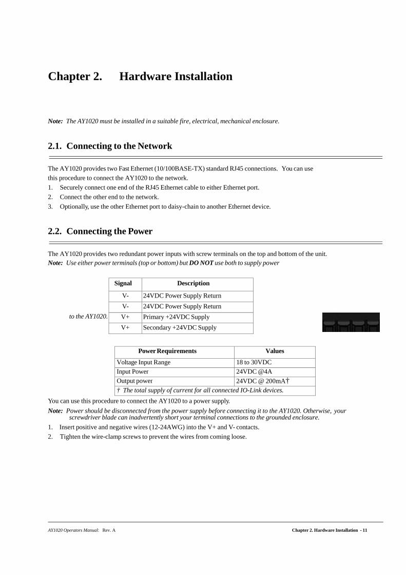
2.2. Connecting the Power
The AY1020 provides two redundant power inputs with screw terminals on the top and bottom of the unit. Note: Use either power terminals (top or bottom) but DO NOT use both to supply power
to the AY1020.
Power Requirements Values
Voltage Input Range 18 to 30VDC
Input Power 24VDC @4A
Output power 24VDC @ 200mA† † The total supply of current for all connected IO-Link devices.
You can use this procedure to connect the AY1020 to a power supply.
Note: Power should be disconnected from the power supply before connecting it to the AY1020. Otherwise, your screwdriver blade can inadvertently short your terminal connections to the grounded enclosure.
1. Insert positive and negative wires (12-24AWG) into the V+ and V- contacts.
2. Tighten the wire-clamp screws to prevent the wires from coming loose.
Signal Description
V- 24VDC Power Supply Return
V- 24VDC Power Supply Return
V+ Primary +24VDC Supply
V+ Secondary +24VDC Supply
Connecting the Power
12 - Chapter 2. Hardware Installation AY1020 Operators Manual: Rev. A
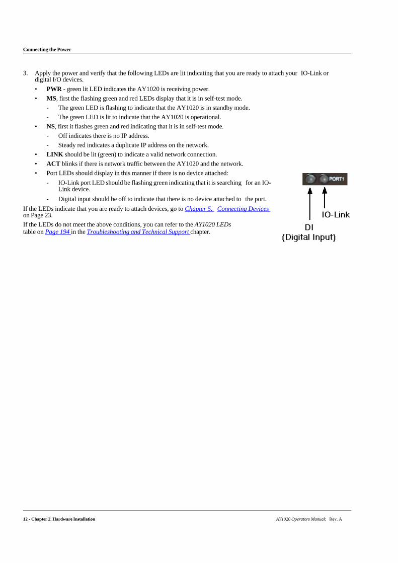
3. Apply the power and verify that the following LEDs are lit indicating that you are ready to attach your IO-Link or digital I/O devices.
• PWR - green lit LED indicates the AY1020 is receiving power.
• MS, first the flashing green and red LEDs display that it is in self-test mode.
- The green LED is flashing to indicate that the AY1020 is in standby mode.
- The green LED is lit to indicate that the AY1020 is operational.
• NS, first it flashes green and red indicating that it is in self-test mode.
- Off indicates there is no IP address.
- Steady red indicates a duplicate IP address on the network.
• LINK should be lit (green) to indicate a valid network connection.
• ACT blinks if there is network traffic between the AY1020 and the network.
• Port LEDs should display in this manner if there is no device attached:
- IO-Link port LED should be flashing green indicating that it is searching for an IO-Link device.
- Digital input should be off to indicate that there is no device attached to the port.
If the LEDs indicate that you are ready to attach devices, go to Chapter 5. Connecting Devices on Page 23.
If the LEDs do not meet the above conditions, you can refer to the AY1020 LEDs table on Page 194 in the Troubleshooting and Technical Support chapter.
Chapter 3. Initial Configuration
AY1020 Operators Manual: Rev. A Chapter 3. Initial Configuration - 13
The following topics are discussed in this chapter.
• Using the Web Interface to Program the Network on Page 13
• Setting User Accounts and Passwords on Page 15
• Configuring Miscellaneous Settings on Page 18
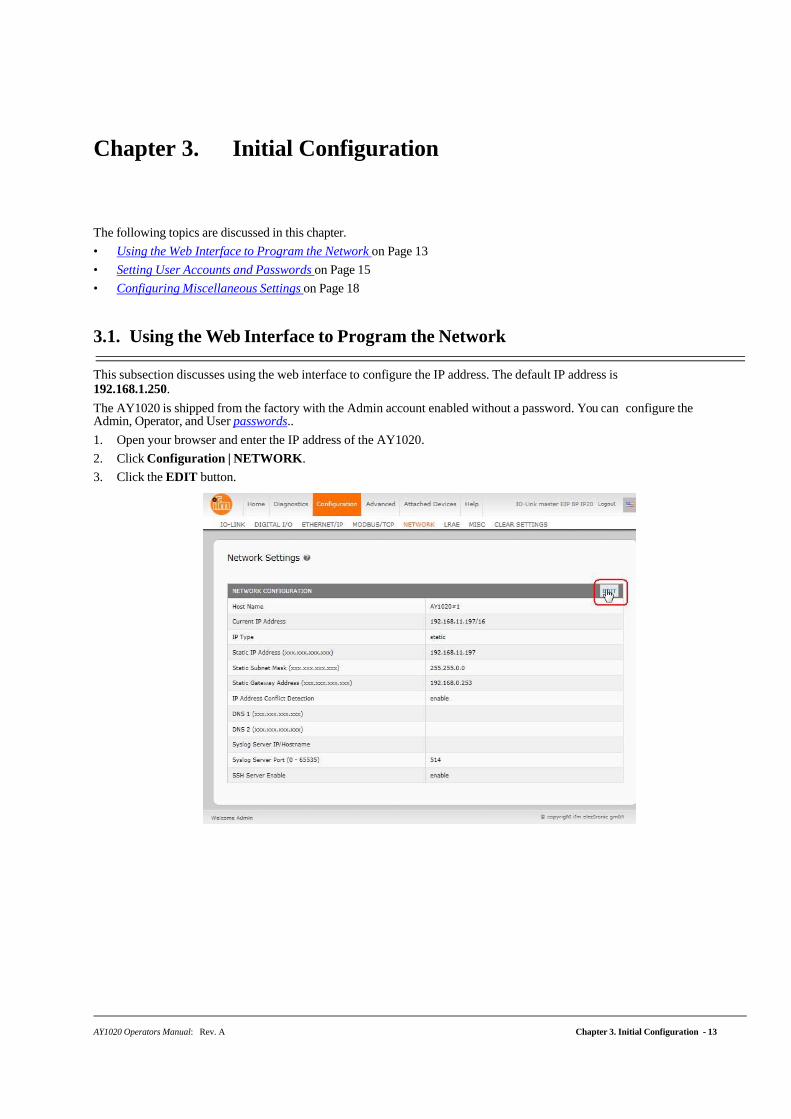
3.1. Using the Web Interface to Program the Network
This subsection discusses using the web interface to configure the IP address. The default IP address is 192.168.1.250.
The AY1020 is shipped from the factory with the Admin account enabled without a password. You can configure the Admin, Operator, and User passwords..
1. Open your browser and enter the IP address of the AY1020.
2. Click Configuration | NETWORK.
3. Click the EDIT button.
Using the Web Interface to Program the Network
14 - Chapter 3. Initial Configuration AY1020 Operators Manual: Rev. A
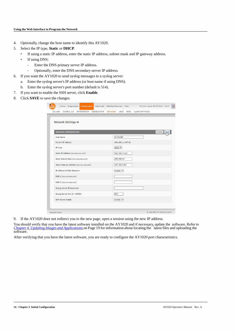
4. Optionally, change the host name to identify this AY1020.
5. Select the IP type, Static or DHCP.
• If using a static IP address, enter the static IP address, subnet mask and IP gateway address.
• If using DNS:
- Enter the DNS primary server IP address.
- Optionally, enter the DNS secondary server IP address.
6. If you want the AY1020 to send syslog messages to a syslog server:
a. Enter the syslog server's IP address (or host name if using DNS).
b. Enter the syslog server's port number (default is 514).
7. If you want to enable the SSH server, click Enable.
8. Click SAVE to save the changes.
9. If the AY1020 does not redirect you to the new page, open a session using the new IP address.
You should verify that you have the latest software installed on the AY1020 and if necessary, update the software. Refer to Chapter 4. Updating Images and Applications on Page 19 for information about locating the latest files and uploading the software.
After verifying that you have the latest software, you are ready to configure the AY1020 port characteristics.
AY1020 Operators Manual: Rev. A Chapter 3. Initial Configuration - 15
Setting User Accounts and Passwords
3.2. Setting User Accounts and Passwords
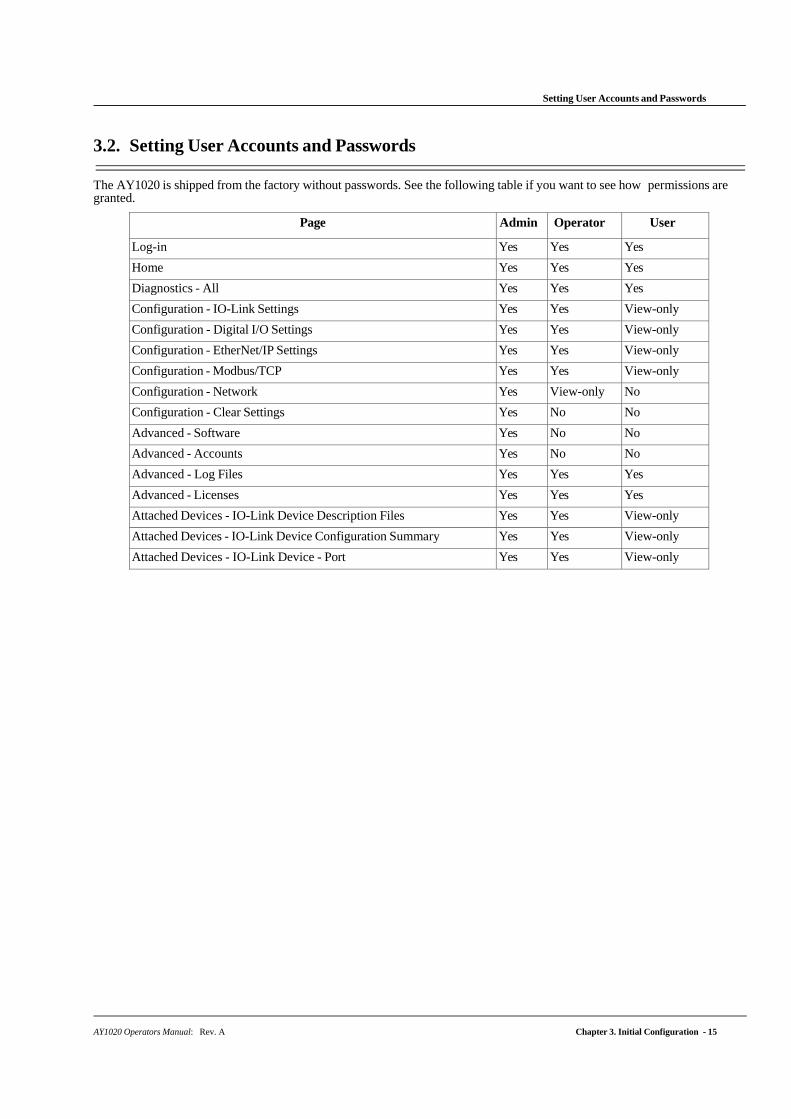
The AY1020 is shipped from the factory without passwords. See the following table if you want to see how permissions are granted.
Page Admin Operator User
Log-in Yes Yes Yes
Home Yes Yes Yes
Diagnostics - All Yes Yes Yes
Configuration - IO-Link Settings Yes Yes View-only
Configuration - Digital I/O Settings Yes Yes View-only
Configuration - EtherNet/IP Settings Yes Yes View-only
Configuration - Modbus/TCP Yes Yes View-only
Configuration - Network Yes View-only No
Configuration - Clear Settings Yes No No
Advanced - Software Yes No No
Advanced - Accounts Yes No No
Advanced - Log Files Yes Yes Yes
Advanced - Licenses Yes Yes Yes
Attached Devices - IO-Link Device Description Files Yes Yes View-only
Attached Devices - IO-Link Device Configuration Summary Yes Yes View-only
Attached Devices - IO-Link Device - Port Yes Yes View-only
16 - Chapter 3. Initial Configuration AY1020 Operators Manual: Rev. A
Setting User Accounts and Passwords
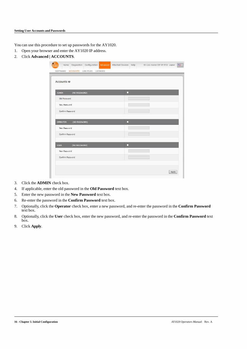
You can use this procedure to set up passwords for the AY1020.
1. Open your browser and enter the AY1020 IP address.
2. Click Advanced | ACCOUNTS.
3. Click the ADMIN check box.
4. If applicable, enter the old password in the Old Password text box.
5. Enter the new password in the New Password text box.
6. Re-enter the password in the Confirm Password text box.
7. Optionally, click the Operator check box, enter a new password, and re-enter the password in the Confirm Password text box.
8. Optionally, click the User check box, enter the new password, and re-enter the password in the Confirm Password text box.
9. Click Apply.
AY1020 Operators Manual: Rev. A Chapter 3. Initial Configuration - 17
Setting User Accounts and Passwords
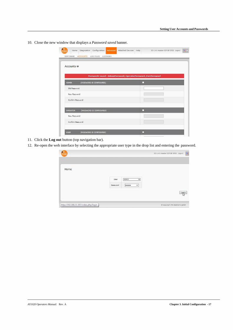
10. Close the new window that displays a Password saved banner.
11. Click the Log out button (top navigation bar).
12. Re-open the web interface by selecting the appropriate user type in the drop list and entering the password.
18 - Chapter 3. Initial Configuration AY1020 Operators Manual: Rev. A
Configuring Miscellaneous Settings
3.3. Configuring Miscellaneous Settings
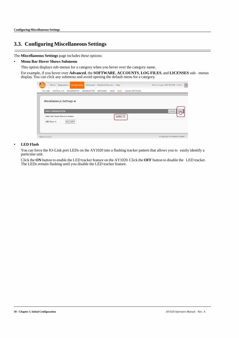
The Miscellaneous Settings page includes these options:
• Menu Bar Hover Shows Submenu
This option displays sub-menus for a category when you hover over the category name.
For example, if you hover over Advanced, the SOFTWARE, ACCOUNTS, LOG FILES, and LICENSES sub- menus display. You can click any submenu and avoid opening the default menu for a category.
• LED Flash
You can force the IO-Link port LEDs on the AY1020 into a flashing tracker pattern that allows you to easily identify a particular unit.
Click the ON button to enable the LED tracker feature on the AY1020. Click the OFF button to disable the LED tracker. The LEDs remain flashing until you disable the LED tracker feature.
AY1020 Operators Manual: Rev. A Chapter 4. Updating Images and Applications - 19
Chapter 4. Updating Images and Applications
This chapter provides an overview of the software (images and applications) on the AY1020. In addition it contains procedures to update images (Page 21) and application subassemblies (Page 22).
After verifying that the AY1020 contains the latest software, the next step is to configure the port characteristics using Chapter 6. IO-Link Port Configuration on Page 27.
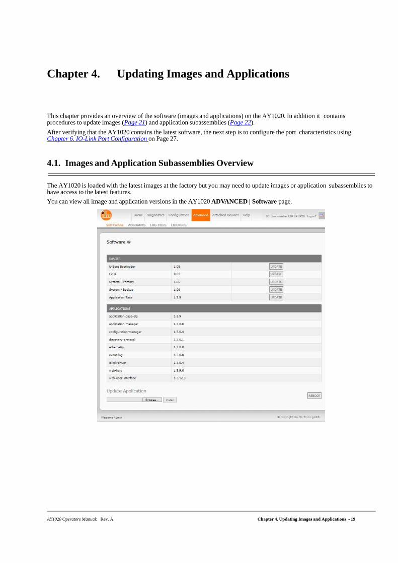
4.1. Images and Application Subassemblies Overview
The AY1020 is loaded with the latest images at the factory but you may need to update images or application subassemblies to have access to the latest features.
You can view all image and application versions in the AY1020 ADVANCED | Software page.
20 - Chapter 4. Updating Images and Applications AY1020 Operators Manual: Rev. A
Images
4.1.1. Images
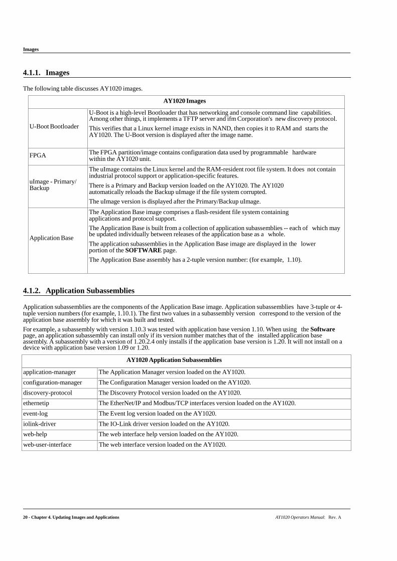
The following table discusses AY1020 images.
AY1020 Images
U-Boot Bootloader
U-Boot is a high-level Bootloader that has networking and console command line capabilities. Among other things, it implements a TFTP server and ifm Corporation's new discovery protocol.
This verifies that a Linux kernel image exists in NAND, then copies it to RAM and starts the AY1020. The U-Boot version is displayed after the image name.
FPGA The FPGA partition/image contains configuration data used by programmable hardware within the AY1020 unit.
uImage - Primary/ Backup
The uImage contains the Linux kernel and the RAM-resident root file system. It does not contain industrial protocol support or application-specific features.
There is a Primary and Backup version loaded on the AY1020. The AY1020 automatically reloads the Backup uImage if the file system corrupted.
The uImage version is displayed after the Primary/Backup uImage.
Application Base
The Application Base image comprises a flash-resident file system containing applications and protocol support.
The Application Base is built from a collection of application subassemblies -- each of which may be updated individually between releases of the application base as a whole.
The application subassemblies in the Application Base image are displayed in the lower portion of the SOFTWARE page.
The Application Base assembly has a 2-tuple version number: (for example, 1.10).
4.1.2. Application Subassemblies
Application subassemblies are the components of the Application Base image. Application subassemblies have 3-tuple or 4-tuple version numbers (for example, 1.10.1). The first two values in a subassembly version correspond to the version of the application base assembly for which it was built and tested.
For example, a subassembly with version 1.10.3 was tested with application base version 1.10. When using the Software page, an application subassembly can install only if its version number matches that of the installed application base assembly. A subassembly with a version of 1.20.2.4 only installs if the application base version is 1.20. It will not install on a device with application base version 1.09 or 1.20.
AY1020 Application Subassemblies
application-manager The Application Manager version loaded on the AY1020.
configuration-manager The Configuration Manager version loaded on the AY1020.
discovery-protocol The Discovery Protocol version loaded on the AY1020.
ethernetip The EtherNet/IP and Modbus/TCP interfaces version loaded on the AY1020.
event-log The Event log version loaded on the AY1020.
iolink-driver The IO-Link driver version loaded on the AY1020.
web-help The web interface help version loaded on the AY1020.
web-user-interface The web interface version loaded on the AY1020.
AY1020 Operators Manual: Rev. A Chapter 4. Updating Images and Applications - 21
Using the Web Interface to Update Software
4.2. Using the Web Interface to Update Software
The upper portion of this page is used to update the AY1020 images. The lower portion of this page is used for updating application subassemblies that are integrated in the Application Base.
Typically, the latest application subassemblies are available in the Application Base image. There may times when a feature enhancement or bug fix is available in an application subassembly and not yet available in the Application Base image.
4.2.1. Updating Images
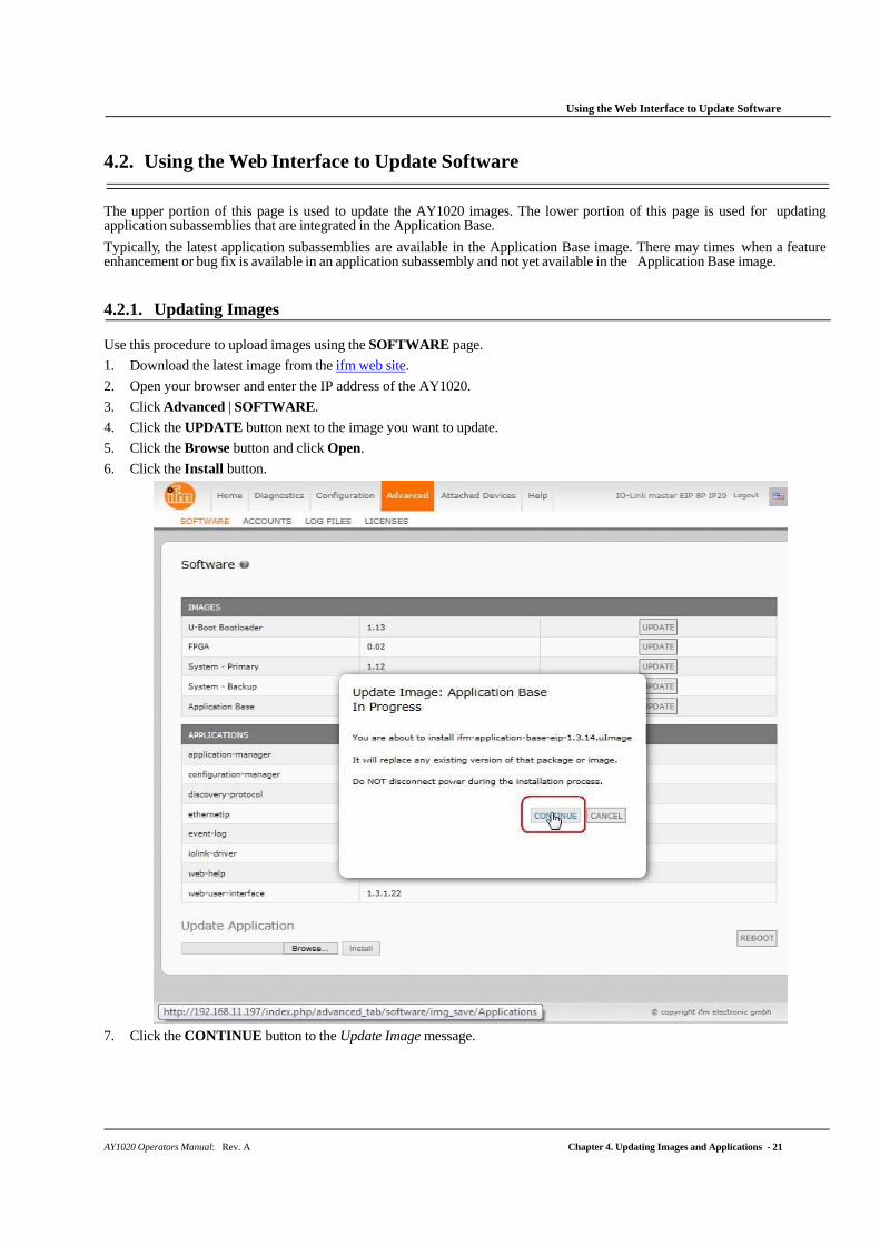
Use this procedure to upload images using the SOFTWARE page.
1. Download the latest image from the ifm web site.
2. Open your browser and enter the IP address of the AY1020.
3. Click Advanced | SOFTWARE.
4. Click the UPDATE button next to the image you want to update.
5. Click the Browse button and click Open.
6. Click the Install button.
7. Click the CONTINUE button to the Update Image message.
22 - Chapter 4. Updating Images and Applications AY1020 Operators Manual: Rev. A
Updating Application Subassemblies
8. Click OK to close the Update Image Successful message.
Note: Some images may require the AY1020 web server to restart.
4.2.2. Updating Application Subassemblies
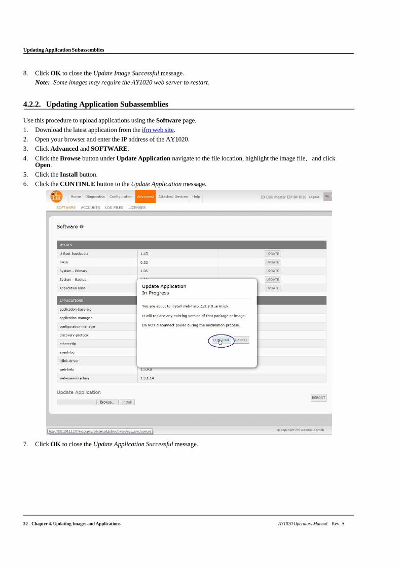
Use this procedure to upload applications using the Software page.
1. Download the latest application from the ifm web site.
2. Open your browser and enter the IP address of the AY1020.
3. Click Advanced and SOFTWARE.
4. Click the Browse button under Update Application navigate to the file location, highlight the image file, and click Open.
5. Click the Install button.
6. Click the CONTINUE button to the Update Application message.
7. Click OK to close the Update Application Successful message.
AY1020 Operators Manual: Rev. A Chapter 5. Connecting Devices - 23
Chapter 5. Connecting Devices
This chapter discusses connecting devices to the AY1020.
After connecting your devices to the AY1020, you may need to use the next chapter to configure an appropriate IP address for your environment using Chapter 3. Initial Configuration on Page 13 before doing any port configuration.
5.1. Connecting to IO-Link Ports
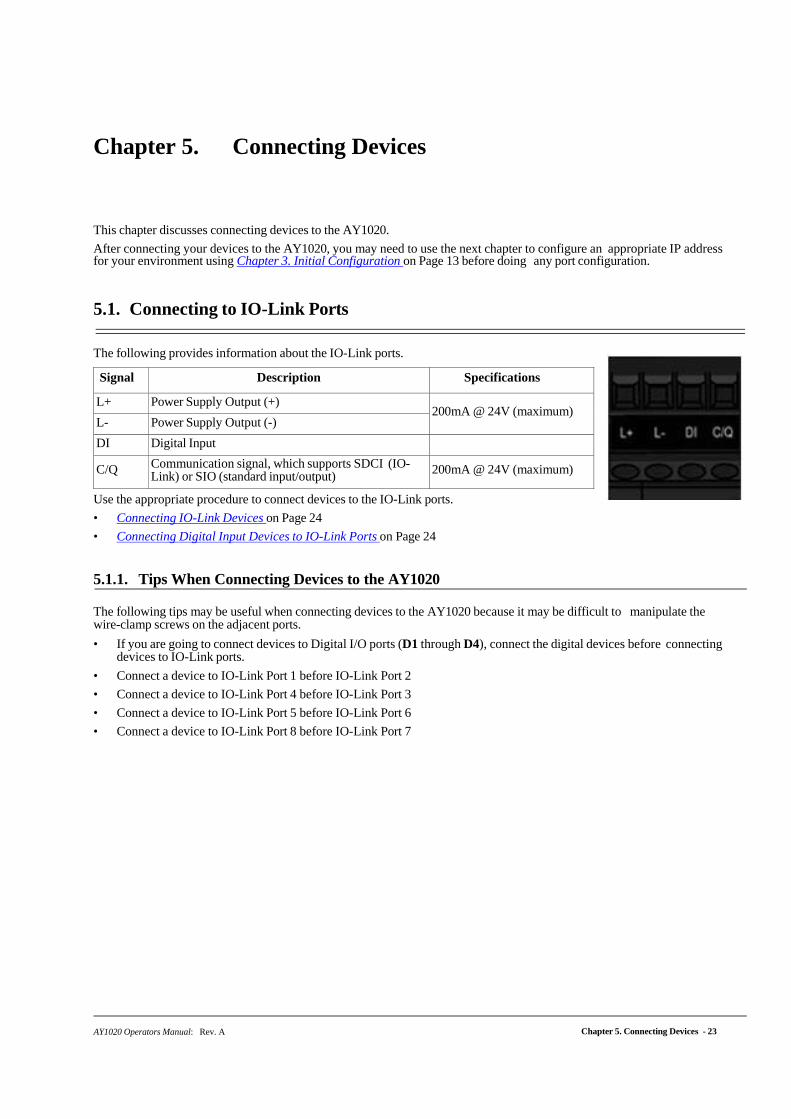
The following provides information about the IO-Link ports.
Signal Description Specifications
L+ Power Supply Output (+) 200mA @ 24V (maximum)
L- Power Supply Output (-)
DI Digital Input
C/Q Communication signal, which supports SDCI (IO-Link) or SIO (standard input/output) 200mA @ 24V (maximum)
Use the appropriate procedure to connect devices to the IO-Link ports.
• Connecting IO-Link Devices on Page 24
• Connecting Digital Input Devices to IO-Link Ports on Page 24
5.1.1. Tips When Connecting Devices to the AY1020
The following tips may be useful when connecting devices to the AY1020 because it may be difficult to manipulate the wire-clamp screws on the adjacent ports.
• If you are going to connect devices to Digital I/O ports (D1 through D4), connect the digital devices before connecting devices to IO-Link ports.
• Connect a device to IO-Link Port 1 before IO-Link Port 2
• Connect a device to IO-Link Port 4 before IO-Link Port 3
• Connect a device to IO-Link Port 5 before IO-Link Port 6
• Connect a device to IO-Link Port 8 before IO-Link Port 7
24 - Chapter 5. Connecting Devices AY1020 Operators Manual: Rev. A
Connecting IO-Link Devices
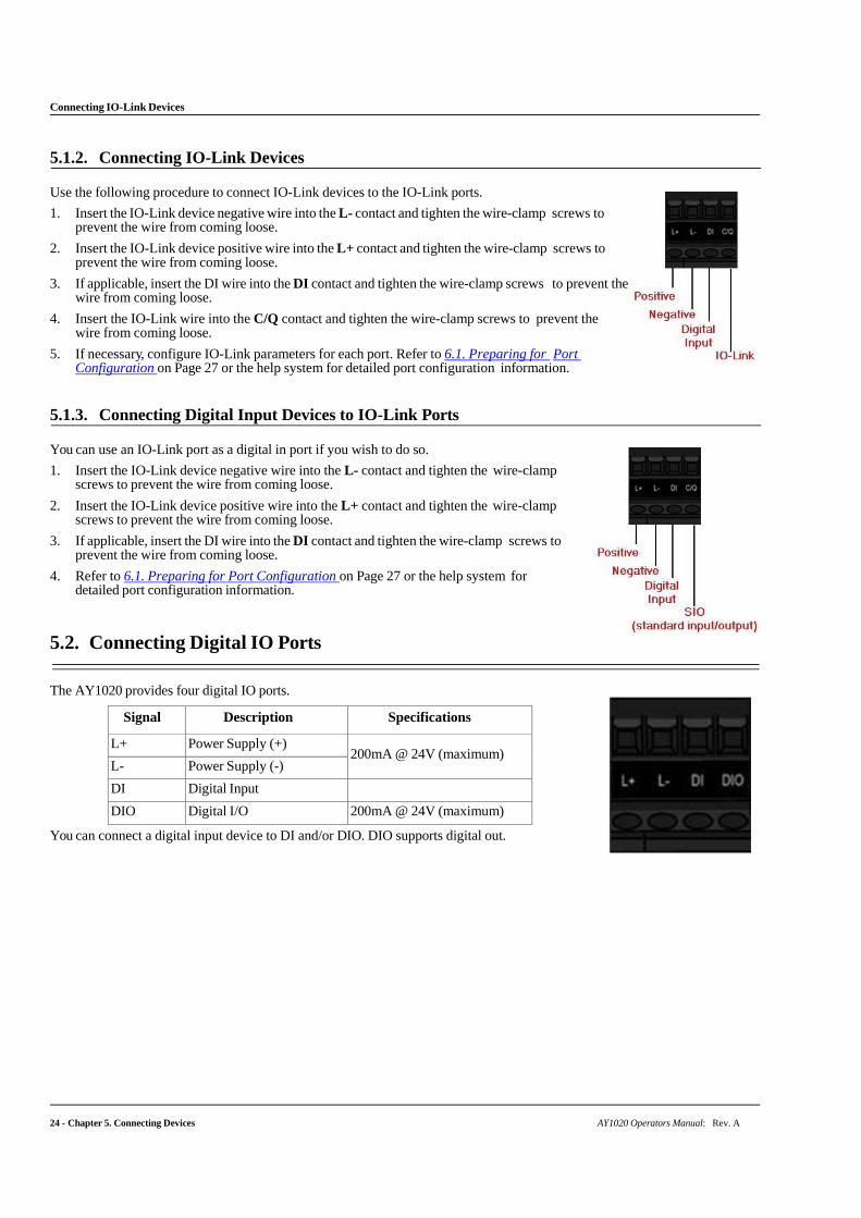
5.1.2. Connecting IO-Link Devices
Use the following procedure to connect IO-Link devices to the IO-Link ports.
1. Insert the IO-Link device negative wire into the L- contact and tighten the wire-clamp screws to prevent the wire from coming loose.
2. Insert the IO-Link device positive wire into the L+ contact and tighten the wire-clamp screws to prevent the wire from coming loose.
3. If applicable, insert the DI wire into the DI contact and tighten the wire-clamp screws to prevent the wire from coming loose.
4. Insert the IO-Link wire into the C/Q contact and tighten the wire-clamp screws to prevent the wire from coming loose.
5. If necessary, configure IO-Link parameters for each port. Refer to 6.1. Preparing for Port Configuration on Page 27 or the help system for detailed port configuration information.
5.1.3. Connecting Digital Input Devices to IO-Link Ports
You can use an IO-Link port as a digital in port if you wish to do so.
1. Insert the IO-Link device negative wire into the L- contact and tighten the wire-clamp screws to prevent the wire from coming loose.
2. Insert the IO-Link device positive wire into the L+ contact and tighten the wire-clamp screws to prevent the wire from coming loose.
3. If applicable, insert the DI wire into the DI contact and tighten the wire-clamp screws to prevent the wire from coming loose.
4. Refer to 6.1. Preparing for Port Configuration on Page 27 or the help system for detailed port configuration information.
5.2. Connecting Digital IO Ports
The AY1020 provides four digital IO ports.
Signal Description Specifications
L+ Power Supply (+) 200mA @ 24V (maximum)
L- Power Supply (-)
DI Digital Input
DIO Digital I/O 200mA @ 24V (maximum)
You can connect a digital input device to DI and/or DIO. DIO supports digital out.
AY1020 Operators Manual: Rev. A Chapter 5. Connecting Devices - 25
Connecting to DI
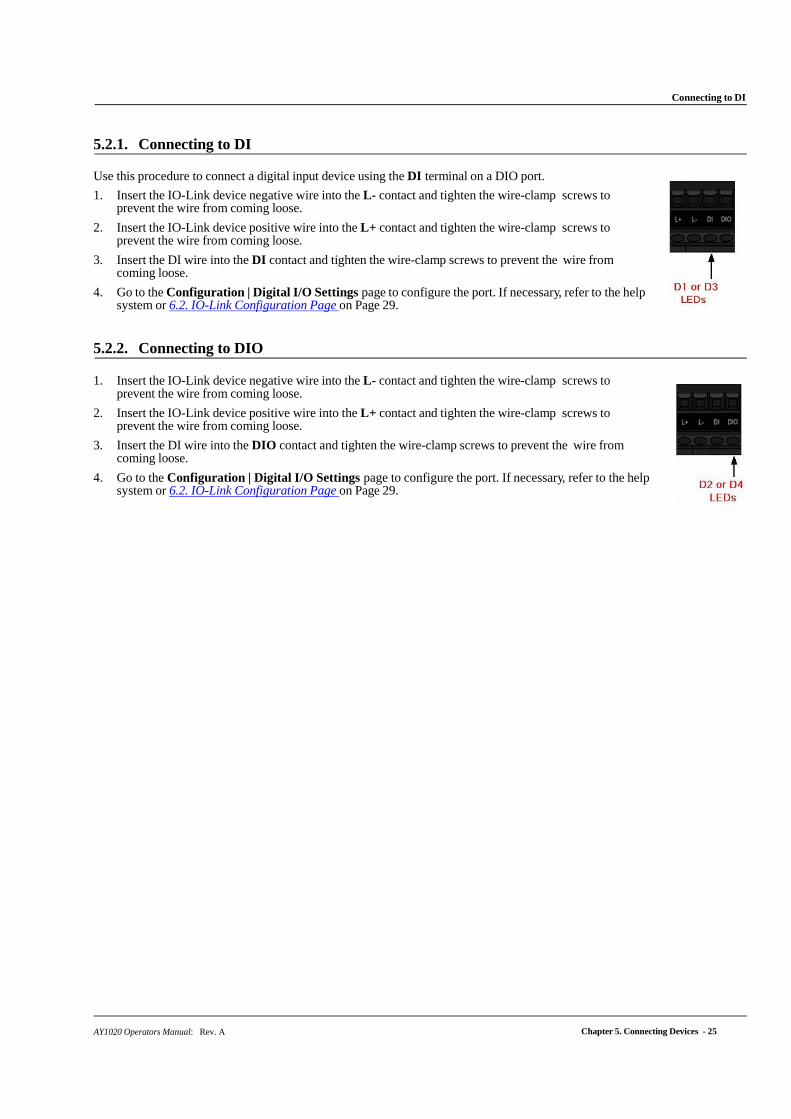
5.2.1. Connecting to DI
Use this procedure to connect a digital input device using the DI terminal on a DIO port.
1. Insert the IO-Link device negative wire into the L- contact and tighten the wire-clamp screws to prevent the wire from coming loose.
2. Insert the IO-Link device positive wire into the L+ contact and tighten the wire-clamp screws to prevent the wire from coming loose.
3. Insert the DI wire into the DI contact and tighten the wire-clamp screws to prevent the wire from coming loose.
4. Go to the Configuration | Digital I/O Settings page to configure the port. If necessary, refer to the help system or 6.2. IO-Link Configuration Page on Page 29.
5.2.2. Connecting to DIO
1. Insert the IO-Link device negative wire into the L- contact and tighten the wire-clamp screws to
prevent the wire from coming loose.
2. Insert the IO-Link device positive wire into the L+ contact and tighten the wire-clamp screws to prevent the wire from coming loose.
3. Insert the DI wire into the DIO contact and tighten the wire-clamp screws to prevent the wire from coming loose.
4. Go to the Configuration | Digital I/O Settings page to configure the port. If necessary, refer to the help system or 6.2. IO-Link Configuration Page on Page 29.

Connecting to DIO
26 - Chapter 5. Connecting Devices AY1020 Operators Manual: Rev. A
AY1020 Operators Manual: Rev. A Chapter 6. IO-Link Port Configuration - 27
Chapter 6. IO-Link Port Configuration
This chapter discusses port configuration, which includes these topics:
• Preparing for Port Configuration
• IO-Link Configuration Page on Page 29
• EtherNet/IP Settings Configuration Page on Page 34
• Modbus/TCP Settings Configuration Page on Page 41
Note: See Chapter 7. Dedicated Digital I/O Port Configuration on Page 47 for information about configuring dedicated digital I/O ports.
Depending on your environment, the IO-Link master you may not need to change many of the default options.
6.1. Preparing for Port Configuration
Before beginning port configuration, you may want to verify that the connected device is functioning.
1. If necessary, log into the IO-Link master.
2. Click Diagnostics| IO-Link Diagnostics.
3. Review the Port Status and IOLink State.
Port Status
Operational, PDI Valid An IO-Link device is operating on the port that has received valid PDI data.
Operational An IO-Link device is operating on the port that has not received valid PDI data.
Inactive
One of the following conditions exists:
• A valid IO-Link device is not connected to the port.
• A digital input or output device is connected to the port but the configured Port Mode is not correct.
IOLink State
Operate Port is functioning correctly in IO-Link mode but has not received valid PDI data. This may also display during a data storage upload or download.
Init The port is attempting initialization.
Reset
One of the following conditions exists:
• The Port Mode configuration is set to Reset.
• The Port Mode configuration is set to DigitalIn or DigitalOut.
DS: Wrong Sensor
Hardware failure (IO-Link LED also flashes red) because there is Data Storage on this port, which does not reflect the attached device.
DV: Wrong Sensor
Hardware failure (IO-Link LED also flashes red) because Device Validation is configured for this port and the wrong device is attached.
DS: Wrong Size
Hardware failure (IO-Link LED also flashes red) because the size of the configuration on the device does not match the size of the configuration stored on the port.
Comm Lost Temporary state after a device is disconnected and before the port is re-initialized.
Pre-operate
Temporary status displayed when the device:
• Is starting up after connection or power-up. • Uploading or downloading automatic data storage.
Note: If a digital input or output device is connected to an IO-Link port, there is no valid data until the port is set to the correct Port Mode.
Preparing for Port Configuration
28 - Chapter 6. IO-Link Port Configuration AY1020 Operators Manual: Rev. A
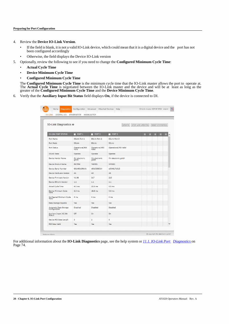
4. Review the Device IO-Link Version.
• If the field is blank, it is not a valid IO-Link device, which could mean that it is a digital device and the port has not been configured accordingly
• Otherwise, the field displays the Device IO-Link version
5. Optionally, review the following to see if you need to change the Configured Minimum Cycle Time:
• Actual Cycle Time
• Device Minimum Cycle Time
• Configured Minimum Cycle Time
The Configured Minimum Cycle Time is the minimum cycle time that the IO-Link master allows the port to operate at. The Actual Cycle Time is negotiated between the IO-Link master and the device and will be at least as long as the greater of the Configured Minimum Cycle Time and the Device Minimum Cycle Time.
6. Verify that the Auxiliary Input Bit Status field displays On, if the device is connected to DI.
For additional information about the IO-Link Diagnostics page, see the help system or 11.1. IO-Link Port Diagnostics on Page 74.

IO-Link Configuration Page
AY1020 Operators Manual: Rev. A Chapter 6. IO-Link Port Configuration - 29
6.2. IO-Link Configuration Page
Use the Configuration | IO-Link Settings page to configure IO-Link port characteristics for the IO-Link master. This
subsection discusses:
• Editing IO-Link Settings on Page 30
• IO-Link Settings Parameters on Page 31.
Editing IO-Link Settings
30 - Chapter 6. IO-Link Port Configuration AY1020 Operators Manual: Rev. A
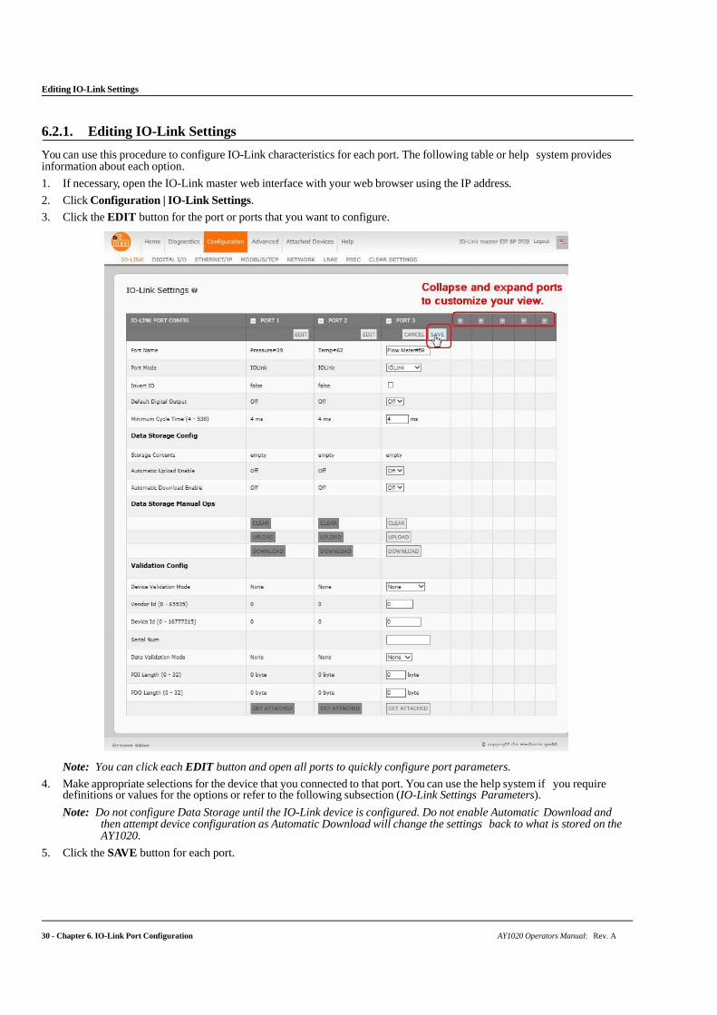
6.2.1. Editing IO-Link Settings
You can use this procedure to configure IO-Link characteristics for each port. The following table or help system provides information about each option.
1. If necessary, open the IO-Link master web interface with your web browser using the IP address.
2. Click Configuration | IO-Link Settings.
3. Click the EDIT button for the port or ports that you want to configure.
Note: You can click each EDIT button and open all ports to quickly configure port parameters.
4. Make appropriate selections for the device that you connected to that port. You can use the help system if you require definitions or values for the options or refer to the following subsection (IO-Link Settings Parameters).
Note: Do not configure Data Storage until the IO-Link device is configured. Do not enable Automatic Download and then attempt device configuration as Automatic Download will change the settings back to what is stored on the AY1020.
5. Click the SAVE button for each port.
IO-Link Settings Parameters
AY1020 Operators Manual: Rev. A Chapter 6. IO-Link Port Configuration - 31
6. Return to the IO-Link Diagnostics page to verify that your changes have taken affect.
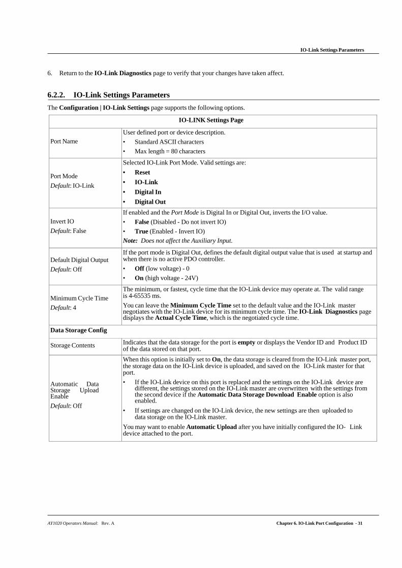
6.2.2. IO-Link Settings Parameters
The Configuration | IO-Link Settings page supports the following options.
IO-LINK Settings Page
Port Name
User defined port or device description.
• Standard ASCII characters
• Max length = 80 characters
Port Mode
Default: IO-Link
Selected IO-Link Port Mode. Valid settings are:
• Reset
• IO-Link
• Digital In
• Digital Out
Invert IO
Default: False
If enabled and the Port Mode is Digital In or Digital Out, inverts the I/O value.
• False (Disabled - Do not invert IO)
• True (Enabled - Invert IO)
Note: Does not affect the Auxiliary Input.
Default Digital Output
Default: Off
If the port mode is Digital Out, defines the default digital output value that is used at startup and when there is no active PDO controller.
• Off (low voltage) - 0
• On (high voltage - 24V)
Minimum Cycle Time
Default: 4
The minimum, or fastest, cycle time that the IO-Link device may operate at. The valid range is 4-65535 ms.
You can leave the Minimum Cycle Time set to the default value and the IO-Link master negotiates with the IO-Link device for its minimum cycle time. The IO-Link Diagnostics page displays the Actual Cycle Time, which is the negotiated cycle time.
Data Storage Config
Storage Contents Indicates that the data storage for the port is empty or displays the Vendor ID and Product ID of the data stored on that port.
Automatic Data Storage Upload Enable
Default: Off
When this option is initially set to On, the data storage is cleared from the IO-Link master port, the storage data on the IO-Link device is uploaded, and saved on the IO-Link master for that port.
• If the IO-Link device on this port is replaced and the settings on the IO-Link device are different, the settings stored on the IO-Link master are overwritten with the settings from the second device if the Automatic Data Storage Download Enable option is also enabled.
• If settings are changed on the IO-Link device, the new settings are then uploaded to data storage on the IO-Link master.
You may want to enable Automatic Upload after you have initially configured the IO- Link device attached to the port.
IO-Link Settings Parameters
32 - Chapter 6. IO-Link Port Configuration AY1020 Operators Manual: Rev. A
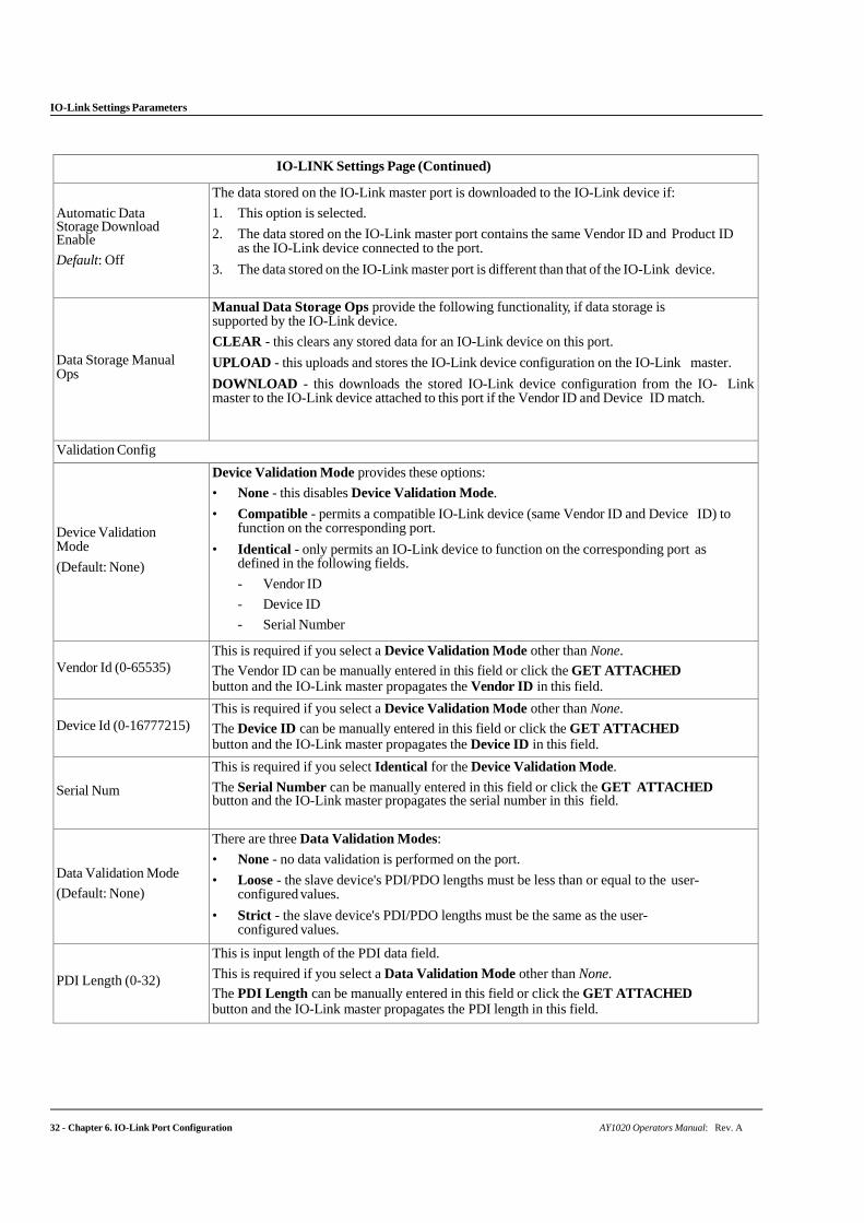
IO-LINK Settings Page (Continued)
Automatic Data Storage Download Enable
Default: Off
The data stored on the IO-Link master port is downloaded to the IO-Link device if:
1. This option is selected.
2. The data stored on the IO-Link master port contains the same Vendor ID and Product ID as the IO-Link device connected to the port.
3. The data stored on the IO-Link master port is different than that of the IO-Link device.
Data Storage Manual Ops
Manual Data Storage Ops provide the following functionality, if data storage is supported by the IO-Link device.
CLEAR - this clears any stored data for an IO-Link device on this port.
UPLOAD - this uploads and stores the IO-Link device configuration on the IO-Link master.
DOWNLOAD - this downloads the stored IO-Link device configuration from the IO- Link master to the IO-Link device attached to this port if the Vendor ID and Device ID match.
Validation Config
Device Validation Mode
(Default: None)
Device Validation Mode provides these options:
• None - this disables Device Validation Mode.
• Compatible - permits a compatible IO-Link device (same Vendor ID and Device ID) to function on the corresponding port.
• Identical - only permits an IO-Link device to function on the corresponding port as defined in the following fields.
- Vendor ID
- Device ID
- Serial Number
Vendor Id (0-65535)
This is required if you select a Device Validation Mode other than None.
The Vendor ID can be manually entered in this field or click the GET ATTACHED button and the IO-Link master propagates the Vendor ID in this field.
Device Id (0-16777215)
This is required if you select a Device Validation Mode other than None.
The Device ID can be manually entered in this field or click the GET ATTACHED button and the IO-Link master propagates the Device ID in this field.
Serial Num
This is required if you select Identical for the Device Validation Mode.
The Serial Number can be manually entered in this field or click the GET ATTACHED button and the IO-Link master propagates the serial number in this field.
Data Validation Mode
(Default: None)
There are three Data Validation Modes:
• None - no data validation is performed on the port.
• Loose - the slave device's PDI/PDO lengths must be less than or equal to the user-configured values.
• Strict - the slave device's PDI/PDO lengths must be the same as the user- configured values.
PDI Length (0-32)
This is input length of the PDI data field.
This is required if you select a Data Validation Mode other than None.
The PDI Length can be manually entered in this field or click the GET ATTACHED button and the IO-Link master propagates the PDI length in this field.
IO-Link Settings Parameters
AY1020 Operators Manual: Rev. A Chapter 6. IO-Link Port Configuration - 33
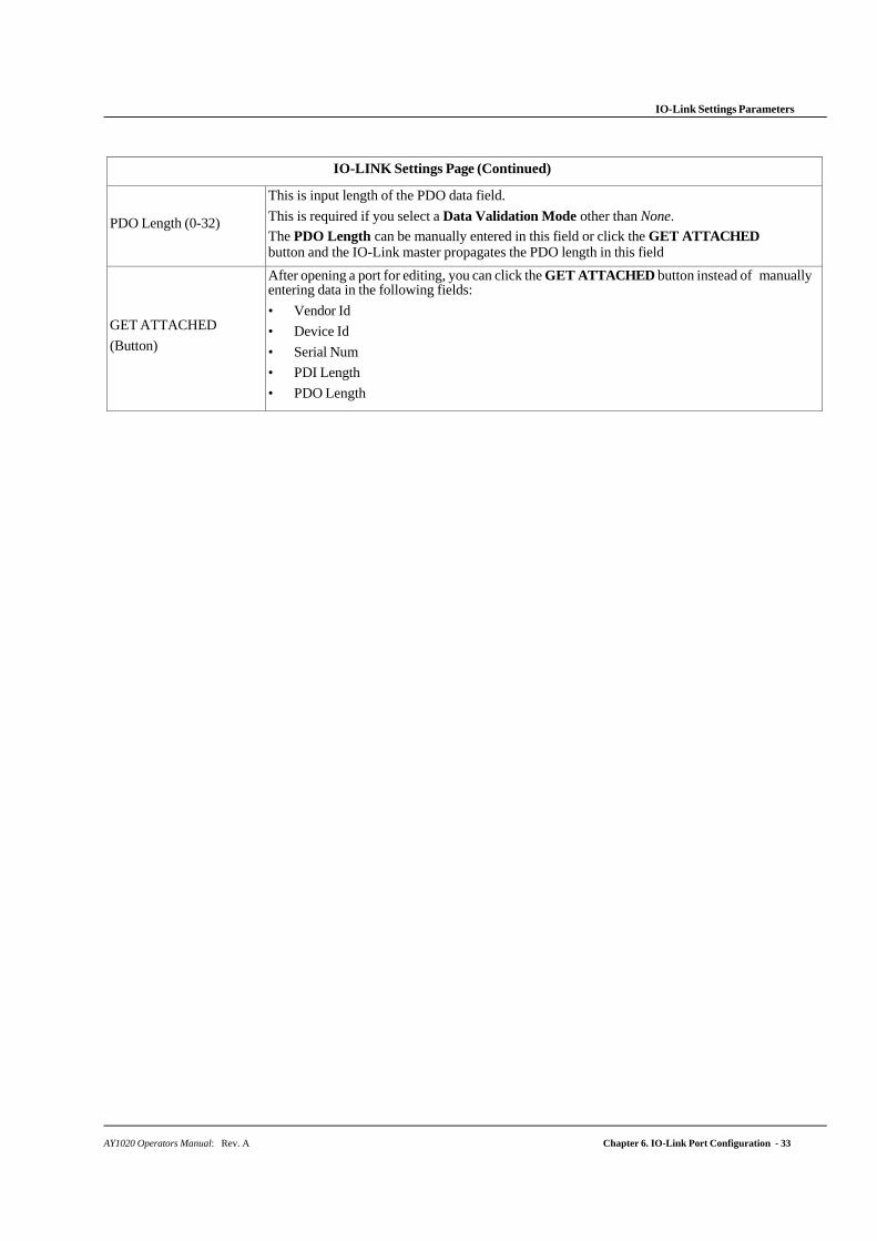
IO-LINK Settings Page (Continued)
PDO Length (0-32)
This is input length of the PDO data field.
This is required if you select a Data Validation Mode other than None.
The PDO Length can be manually entered in this field or click the GET ATTACHED button and the IO-Link master propagates the PDO length in this field
GET ATTACHED
(Button)
After opening a port for editing, you can click the GET ATTACHED button instead of manually entering data in the following fields:
• Vendor Id
• Device Id
• Serial Num
• PDI Length
• PDO Length
34 - Chapter 6. IO-Link Port Configuration AY1020 Operators Manual: Rev. A
EtherNet/IP Settings Configuration Page
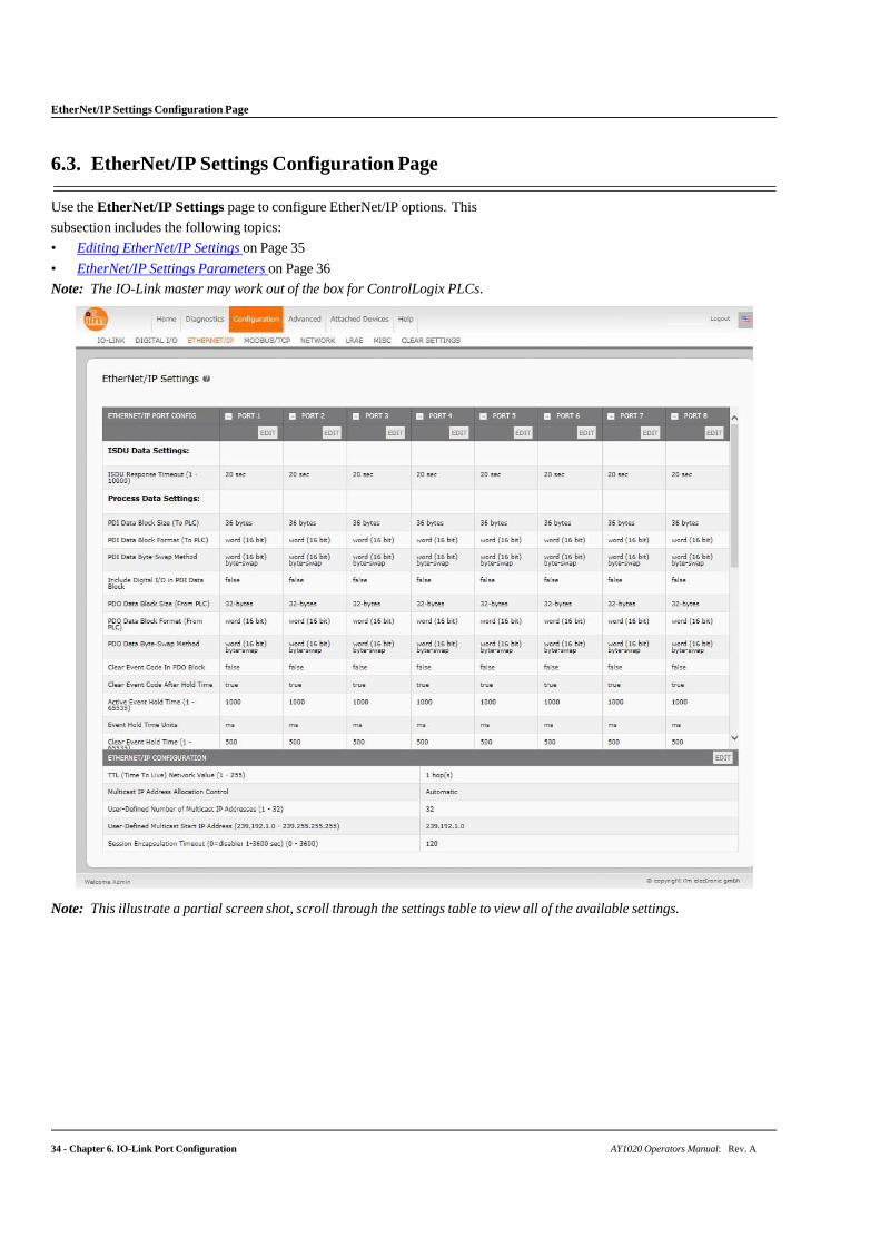
6.3. EtherNet/IP Settings Configuration Page
Use the EtherNet/IP Settings page to configure EtherNet/IP options. This
subsection includes the following topics:
• Editing EtherNet/IP Settings on Page 35
• EtherNet/IP Settings Parameters on Page 36
Note: The IO-Link master may work out of the box for ControlLogix PLCs.
Note: This illustrate a partial screen shot, scroll through the settings table to view all of the available settings.
AY1020 Operators Manual: Rev. A Chapter 6. IO-Link Port Configuration - 35
Editing EtherNet/IP Settings
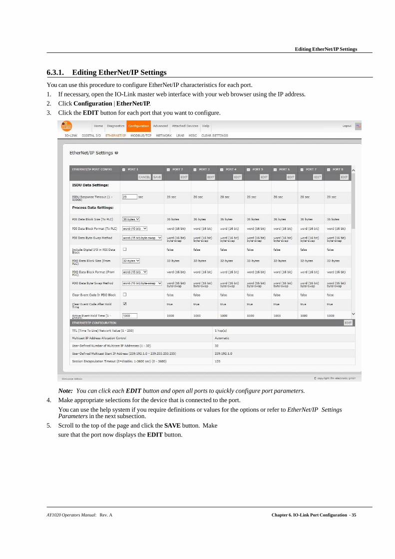
6.3.1. Editing EtherNet/IP Settings
You can use this procedure to configure EtherNet/IP characteristics for each port.
1. If necessary, open the IO-Link master web interface with your web browser using the IP address.
2. Click Configuration | EtherNet/IP.
3. Click the EDIT button for each port that you want to configure.
Note: You can click each EDIT button and open all ports to quickly configure port parameters.
4. Make appropriate selections for the device that is connected to the port.
You can use the help system if you require definitions or values for the options or refer to EtherNet/IP Settings Parameters in the next subsection.
5. Scroll to the top of the page and click the SAVE button. Make
sure that the port now displays the EDIT button.
36 - Chapter 6. IO-Link Port Configuration AY1020 Operators Manual: Rev. A
EtherNet/IP Settings Parameters
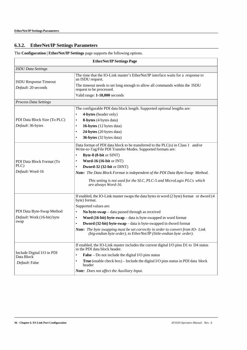
6.3.2. EtherNet/IP Settings Parameters
The Configuration | EtherNet/IP Settings page supports the following options.
EtherNet/IP Settings Page
ISDU Data Settings
ISDU Response Timeout
Default: 20 seconds
The time that the IO-Link master’s EtherNet/IP interface waits for a response to an ISDU request.
The timeout needs to set long enough to allow all commands within the ISDU request to be processed.
Valid range: 1-10,000 seconds
Process Data Settings
PDI Data Block Size (To PLC)
Default: 36-bytes
The configurable PDI data block length. Supported optional lengths are:
• 4-bytes (header only)
• 8-bytes (4 bytes data)
• 16-bytes (12 bytes data)
• 24-bytes (20 bytes data)
• 36-bytes (32 bytes data)
PDI Data Block Format (To PLC)
Default: Word-16
Data format of PDI data block to be transferred to the PLC(s) in Class 1 and/or Write-to-Tag/File PDI Transfer Modes. Supported formats are:
• Byte-8 (8-bit or SINT)
• Word-16 (16-bit or INT)
• Dword-32 (32-bit or DINT)
Note: The Data Block Format is independent of the PDI Data Byte-Swap Method.
This setting is not used for the SLC, PLC-5 and MicroLogix PLCs which are always Word-16.
PDI Data Byte-Swap Method
Default: Work (16-bit) byte swap
If enabled, the IO-Link master swaps the data bytes in word (2 byte) format or dword (4 byte) format.
Supported values are:
• No byte-swap – data passed through as received
• Word (16-bit) byte-swap – data is byte-swapped in word format
• Dword (32-bit) byte-swap – data is byte-swapped in dword format
Note: The byte swapping must be set correctly in order to convert from IO- Link (big-endian byte order), to EtherNet/IP (little-endian byte order).
Include Digital I/O in PDI Data Block
Default: False
If enabled, the IO-Link master includes the current digital I/O pins D1 to D4 status in the PDI data block header.
• False – Do not include the digital I/O pins status
• True (enable check box) – Include the digital I/O pins status in PDI data block header
Note: Does not affect the Auxiliary Input.
AY1020 Operators Manual: Rev. A Chapter 6. IO-Link Port Configuration - 37
EtherNet/IP Settings Parameters
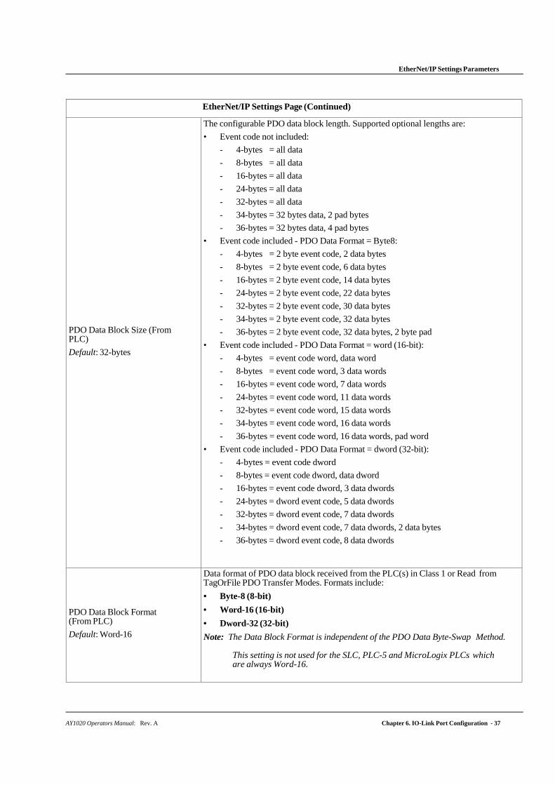
EtherNet/IP Settings Page (Continued)
PDO Data Block Size (From PLC)
Default: 32-bytes
The configurable PDO data block length. Supported optional lengths are:
• Event code not included:
- 4-bytes = all data
- 8-bytes = all data
- 16-bytes = all data
- 24-bytes = all data
- 32-bytes = all data
- 34-bytes = 32 bytes data, 2 pad bytes
- 36-bytes = 32 bytes data, 4 pad bytes
• Event code included - PDO Data Format = Byte8:
- 4-bytes = 2 byte event code, 2 data bytes
- 8-bytes = 2 byte event code, 6 data bytes
- 16-bytes = 2 byte event code, 14 data bytes
- 24-bytes = 2 byte event code, 22 data bytes
- 32-bytes = 2 byte event code, 30 data bytes
- 34-bytes = 2 byte event code, 32 data bytes
- 36-bytes = 2 byte event code, 32 data bytes, 2 byte pad
• Event code included - PDO Data Format = word (16-bit):
- 4-bytes = event code word, data word
- 8-bytes = event code word, 3 data words
- 16-bytes = event code word, 7 data words
- 24-bytes = event code word, 11 data words
- 32-bytes = event code word, 15 data words
- 34-bytes = event code word, 16 data words
- 36-bytes = event code word, 16 data words, pad word
• Event code included - PDO Data Format = dword (32-bit):
- 4-bytes = event code dword
- 8-bytes = event code dword, data dword
- 16-bytes = event code dword, 3 data dwords
- 24-bytes = dword event code, 5 data dwords
- 32-bytes = dword event code, 7 data dwords
- 34-bytes = dword event code, 7 data dwords, 2 data bytes
- 36-bytes = dword event code, 8 data dwords
PDO Data Block Format (From PLC)
Default: Word-16
Data format of PDO data block received from the PLC(s) in Class 1 or Read from TagOrFile PDO Transfer Modes. Formats include:
• Byte-8 (8-bit)
• Word-16 (16-bit)
• Dword-32 (32-bit)
Note: The Data Block Format is independent of the PDO Data Byte-Swap Method.
This setting is not used for the SLC, PLC-5 and MicroLogix PLCs which are always Word-16.
38 - Chapter 6. IO-Link Port Configuration AY1020 Operators Manual: Rev. A
EtherNet/IP Settings Parameters
EtherNet/IP Settings Page (Continued)
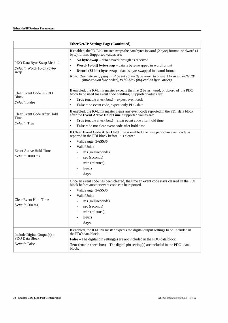
PDO Data Byte-Swap Method
Default: Word (16-bit) byte- swap
If enabled, the IO-Link master swaps the data bytes in word (2 byte) format or dword (4 byte) format. Supported values are:
• No byte-swap – data passed through as received
• Word (16-bit) byte-swap – data is byte-swapped in word format
• Dword (32-bit) byte-swap – data is byte-swapped in dword format
Note: The byte swapping must be set correctly in order to convert from EtherNet/IP (little-endian byte order), to IO-Link (big-endian byte order).
Clear Event Code in PDO Block
Default: False
If enabled, the IO-Link master expects the first 2 bytes, word, or dword of the PDO block to be used for event code handling. Supported values are:
• True (enable check box) = expect event code
• False = no event code, expect only PDO data
Clear Event Code After Hold Time
Default: True
If enabled, the IO-Link master clears any event code reported in the PDI data block after the Event Active Hold Time. Supported values are:
• True (enable check box) = clear event code after hold time
• False = do not clear event code after hold time
Event Active Hold Time
Default: 1000 ms
If Clear Event Code After Hold time is enabled, the time period an event code is reported in the PDI block before it is cleared.
• Valid range: 1-65535
• Valid Units:
- ms (milliseconds)
- sec (seconds)
- min (minutes)
- hours
- days
Clear Event Hold Time
Default: 500 ms
Once an event code has been cleared, the time an event code stays cleared in the PDI block before another event code can be reported.
• Valid range: 1-65535
• Valid Units:
- ms (milliseconds)
- sec (seconds)
- min (minutes)
- hours
- days
Include Digital Output(s) in PDO Data Block
Default: False
If enabled, the IO-Link master expects the digital output settings to be included in the PDO data block.
False – The digital pin setting(s) are not included in the PDO data block.
True (enable check box) – The digital pin setting(s) are included in the PDO data block.
AY1020 Operators Manual: Rev. A Chapter 6. IO-Link Port Configuration - 39
EtherNet/IP Settings Parameters
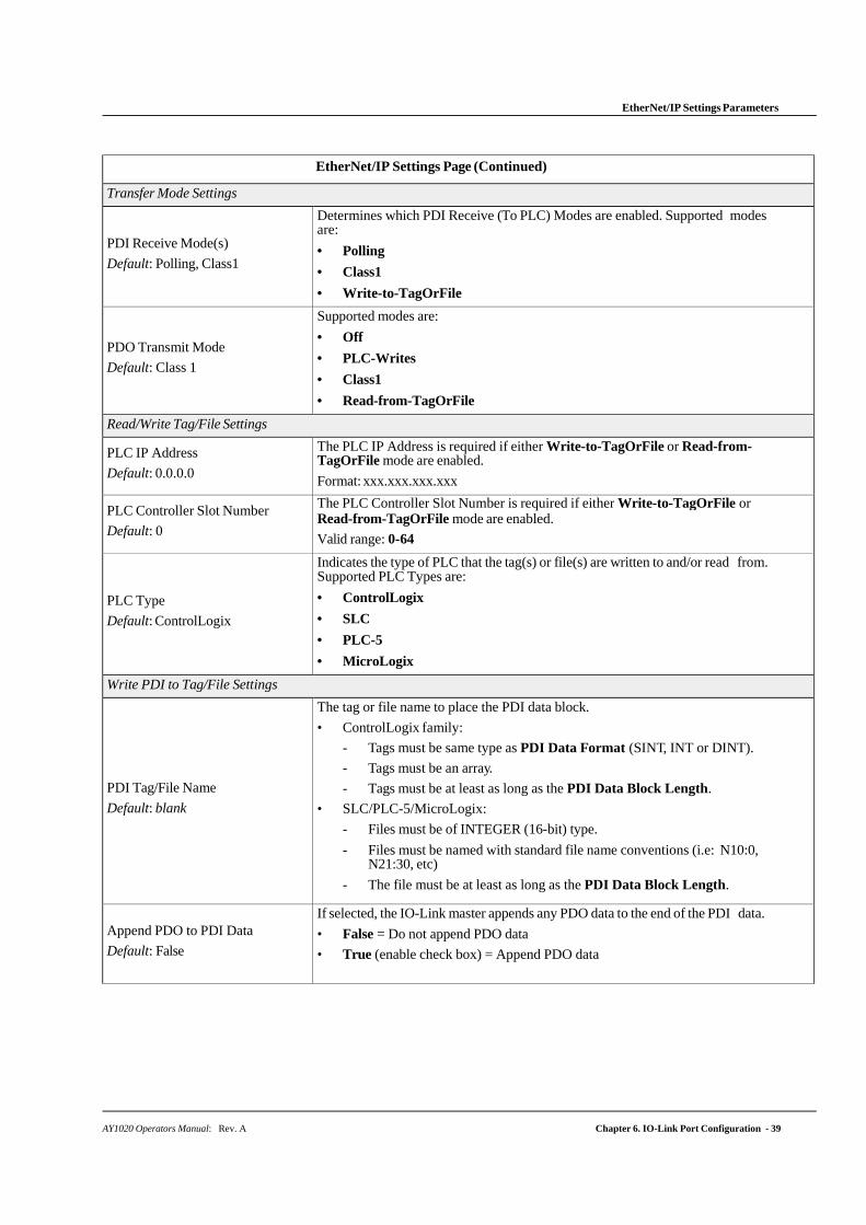
EtherNet/IP Settings Page (Continued)
Transfer Mode Settings
PDI Receive Mode(s)
Default: Polling, Class1
Determines which PDI Receive (To PLC) Modes are enabled. Supported modes are:
• Polling
• Class1
• Write-to-TagOrFile
PDO Transmit Mode
Default: Class 1
Supported modes are:
• Off
• PLC-Writes
• Class1
• Read-from-TagOrFile
Read/Write Tag/File Settings
PLC IP Address
Default: 0.0.0.0
The PLC IP Address is required if either Write-to-TagOrFile or Read-from- TagOrFile mode are enabled.
Format: xxx.xxx.xxx.xxx
PLC Controller Slot Number
Default: 0
The PLC Controller Slot Number is required if either Write-to-TagOrFile or Read-from-TagOrFile mode are enabled.
Valid range: 0-64
PLC Type
Default: ControlLogix
Indicates the type of PLC that the tag(s) or file(s) are written to and/or read from. Supported PLC Types are:
• ControlLogix
• SLC
• PLC-5
• MicroLogix
Write PDI to Tag/File Settings
PDI Tag/File Name
Default: blank
The tag or file name to place the PDI data block.
• ControlLogix family:
- Tags must be same type as PDI Data Format (SINT, INT or DINT).
- Tags must be an array.
- Tags must be at least as long as the PDI Data Block Length.
• SLC/PLC-5/MicroLogix:
- Files must be of INTEGER (16-bit) type.
- Files must be named with standard file name conventions (i.e: N10:0, N21:30, etc)
- The file must be at least as long as the PDI Data Block Length.
Append PDO to PDI Data
Default: False
If selected, the IO-Link master appends any PDO data to the end of the PDI data.
• False = Do not append PDO data
• True (enable check box) = Append PDO data
EtherNet/IP Settings Parameters
40 - Chapter 6. IO-Link Port Configuration AY1020 Operators Manual: Rev. A
EtherNet/IP Settings Page (Continued)
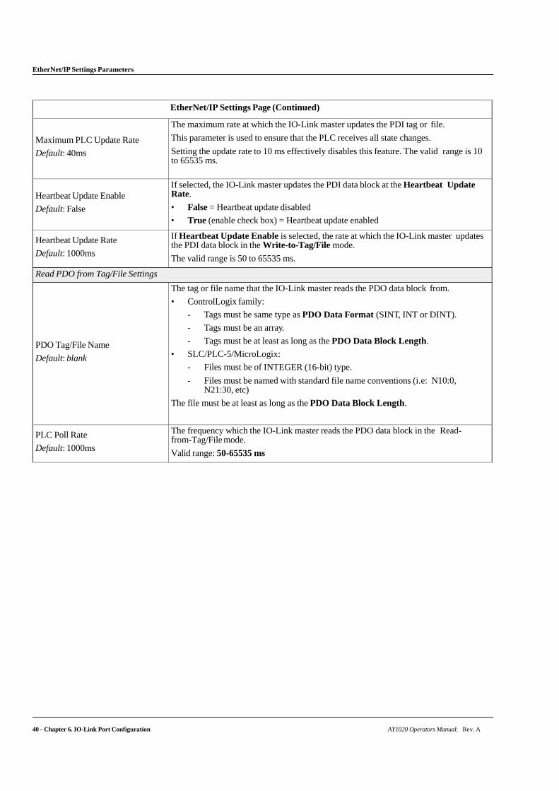
Maximum PLC Update Rate
Default: 40ms
The maximum rate at which the IO-Link master updates the PDI tag or file.
This parameter is used to ensure that the PLC receives all state changes.
Setting the update rate to 10 ms effectively disables this feature. The valid range is 10 to 65535 ms.
Heartbeat Update Enable
Default: False
If selected, the IO-Link master updates the PDI data block at the Heartbeat Update Rate.
• False = Heartbeat update disabled
• True (enable check box) = Heartbeat update enabled
Heartbeat Update Rate
Default: 1000ms
If Heartbeat Update Enable is selected, the rate at which the IO-Link master updates the PDI data block in the Write-to-Tag/File mode.
The valid range is 50 to 65535 ms.
Read PDO from Tag/File Settings
PDO Tag/File Name
Default: blank
The tag or file name that the IO-Link master reads the PDO data block from.
• ControlLogix family:
- Tags must be same type as PDO Data Format (SINT, INT or DINT).
- Tags must be an array.
- Tags must be at least as long as the PDO Data Block Length.
• SLC/PLC-5/MicroLogix:
- Files must be of INTEGER (16-bit) type.
- Files must be named with standard file name conventions (i.e: N10:0, N21:30, etc)
The file must be at least as long as the PDO Data Block Length.
PLC Poll Rate
Default: 1000ms
The frequency which the IO-Link master reads the PDO data block in the Read-from-Tag/File mode.
Valid range: 50-65535 ms
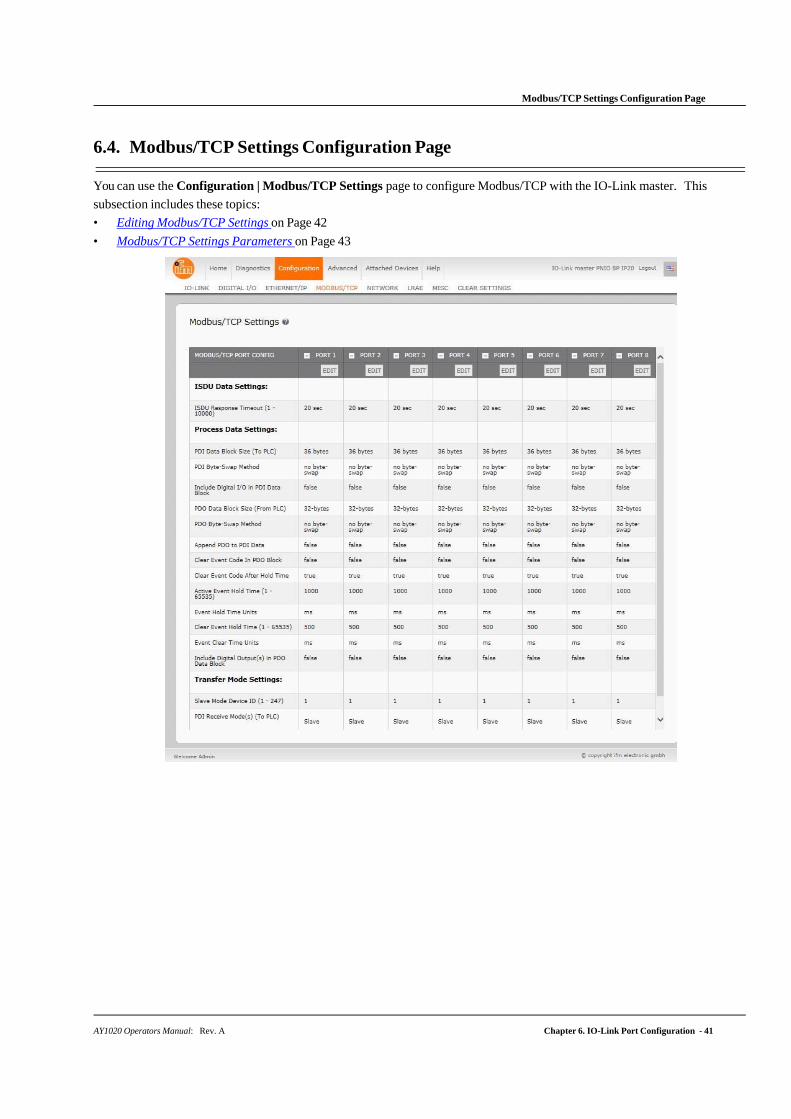
AY1020 Operators Manual: Rev. A Chapter 6. IO-Link Port Configuration - 41
Modbus/TCP Settings Configuration Page
6.4. Modbus/TCP Settings Configuration Page
You can use the Configuration | Modbus/TCP Settings page to configure Modbus/TCP with the IO-Link master. This
subsection includes these topics:
• Editing Modbus/TCP Settings on Page 42
• Modbus/TCP Settings Parameters on Page 43
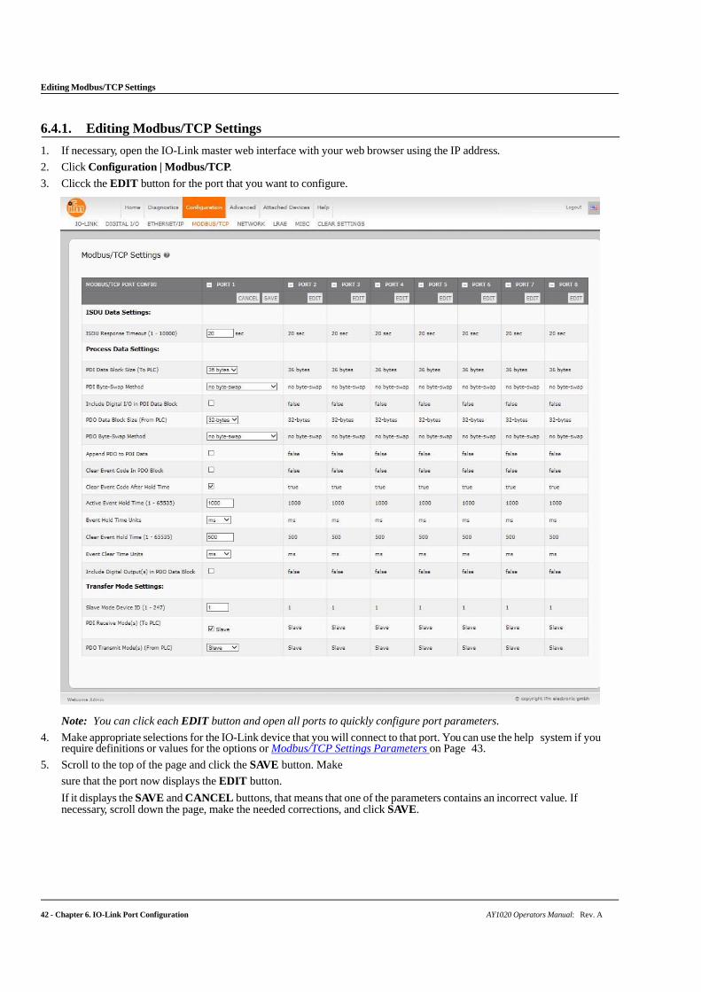
Editing Modbus/TCP Settings
42 - Chapter 6. IO-Link Port Configuration AY1020 Operators Manual: Rev. A
6.4.1. Editing Modbus/TCP Settings
1. If necessary, open the IO-Link master web interface with your web browser using the IP address.
2. Click Configuration | Modbus/TCP.
3. Clicck the EDIT button for the port that you want to configure.
Note: You can click each EDIT button and open all ports to quickly configure port parameters.
4. Make appropriate selections for the IO-Link device that you will connect to that port. You can use the help system if you require definitions or values for the options or Modbus/TCP Settings Parameters on Page 43.
5. Scroll to the top of the page and click the SAVE button. Make
sure that the port now displays the EDIT button.
If it displays the SAVE and CANCEL buttons, that means that one of the parameters contains an incorrect value. If necessary, scroll down the page, make the needed corrections, and click SAVE.
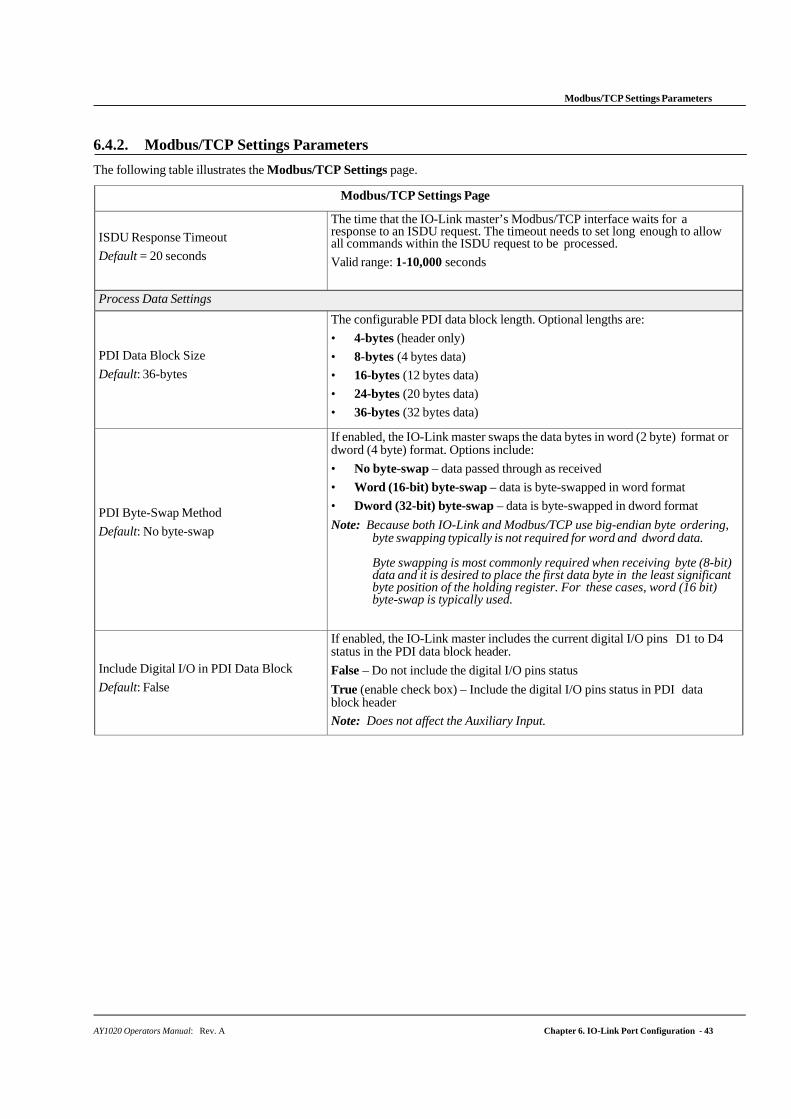
AY1020 Operators Manual: Rev. A Chapter 6. IO-Link Port Configuration - 43
Modbus/TCP Settings Parameters
6.4.2. Modbus/TCP Settings Parameters
The following table illustrates the Modbus/TCP Settings page.
Modbus/TCP Settings Page
ISDU Response Timeout
Default = 20 seconds
The time that the IO-Link master’s Modbus/TCP interface waits for a response to an ISDU request. The timeout needs to set long enough to allow all commands within the ISDU request to be processed.
Valid range: 1-10,000 seconds
Process Data Settings
PDI Data Block Size
Default: 36-bytes
The configurable PDI data block length. Optional lengths are:
• 4-bytes (header only)
• 8-bytes (4 bytes data)
• 16-bytes (12 bytes data)
• 24-bytes (20 bytes data)
• 36-bytes (32 bytes data)
PDI Byte-Swap Method
Default: No byte-swap
If enabled, the IO-Link master swaps the data bytes in word (2 byte) format or dword (4 byte) format. Options include:
• No byte-swap – data passed through as received
• Word (16-bit) byte-swap – data is byte-swapped in word format
• Dword (32-bit) byte-swap – data is byte-swapped in dword format
Note: Because both IO-Link and Modbus/TCP use big-endian byte ordering, byte swapping typically is not required for word and dword data.
Byte swapping is most commonly required when receiving byte (8-bit) data and it is desired to place the first data byte in the least significant byte position of the holding register. For these cases, word (16 bit) byte-swap is typically used.
Include Digital I/O in PDI Data Block
Default: False
If enabled, the IO-Link master includes the current digital I/O pins D1 to D4 status in the PDI data block header.
False – Do not include the digital I/O pins status
True (enable check box) – Include the digital I/O pins status in PDI data block header
Note: Does not affect the Auxiliary Input.
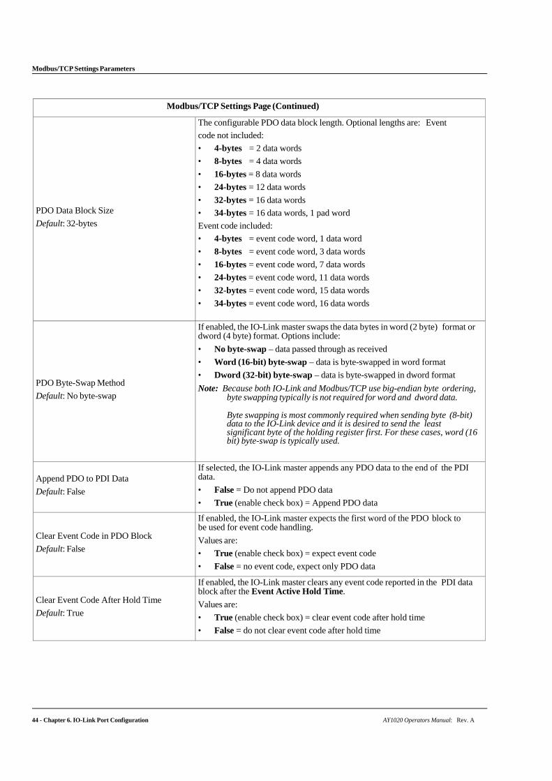
44 - Chapter 6. IO-Link Port Configuration AY1020 Operators Manual: Rev. A
Modbus/TCP Settings Parameters
Modbus/TCP Settings Page (Continued)
PDO Data Block Size
Default: 32-bytes
The configurable PDO data block length. Optional lengths are: Event
code not included:
• 4-bytes = 2 data words
• 8-bytes = 4 data words
• 16-bytes = 8 data words
• 24-bytes = 12 data words
• 32-bytes = 16 data words
• 34-bytes = 16 data words, 1 pad word
Event code included:
• 4-bytes = event code word, 1 data word
• 8-bytes = event code word, 3 data words
• 16-bytes = event code word, 7 data words
• 24-bytes = event code word, 11 data words
• 32-bytes = event code word, 15 data words
• 34-bytes = event code word, 16 data words
PDO Byte-Swap Method
Default: No byte-swap
If enabled, the IO-Link master swaps the data bytes in word (2 byte) format or dword (4 byte) format. Options include:
• No byte-swap – data passed through as received
• Word (16-bit) byte-swap – data is byte-swapped in word format
• Dword (32-bit) byte-swap – data is byte-swapped in dword format
Note: Because both IO-Link and Modbus/TCP use big-endian byte ordering, byte swapping typically is not required for word and dword data.
Byte swapping is most commonly required when sending byte (8-bit) data to the IO-Link device and it is desired to send the least significant byte of the holding register first. For these cases, word (16 bit) byte-swap is typically used.
Append PDO to PDI Data
Default: False
If selected, the IO-Link master appends any PDO data to the end of the PDI data.
• False = Do not append PDO data
• True (enable check box) = Append PDO data
Clear Event Code in PDO Block
Default: False
If enabled, the IO-Link master expects the first word of the PDO block to be used for event code handling.
Values are:
• True (enable check box) = expect event code
• False = no event code, expect only PDO data
Clear Event Code After Hold Time
Default: True
If enabled, the IO-Link master clears any event code reported in the PDI data block after the Event Active Hold Time.
Values are:
• True (enable check box) = clear event code after hold time
• False = do not clear event code after hold time
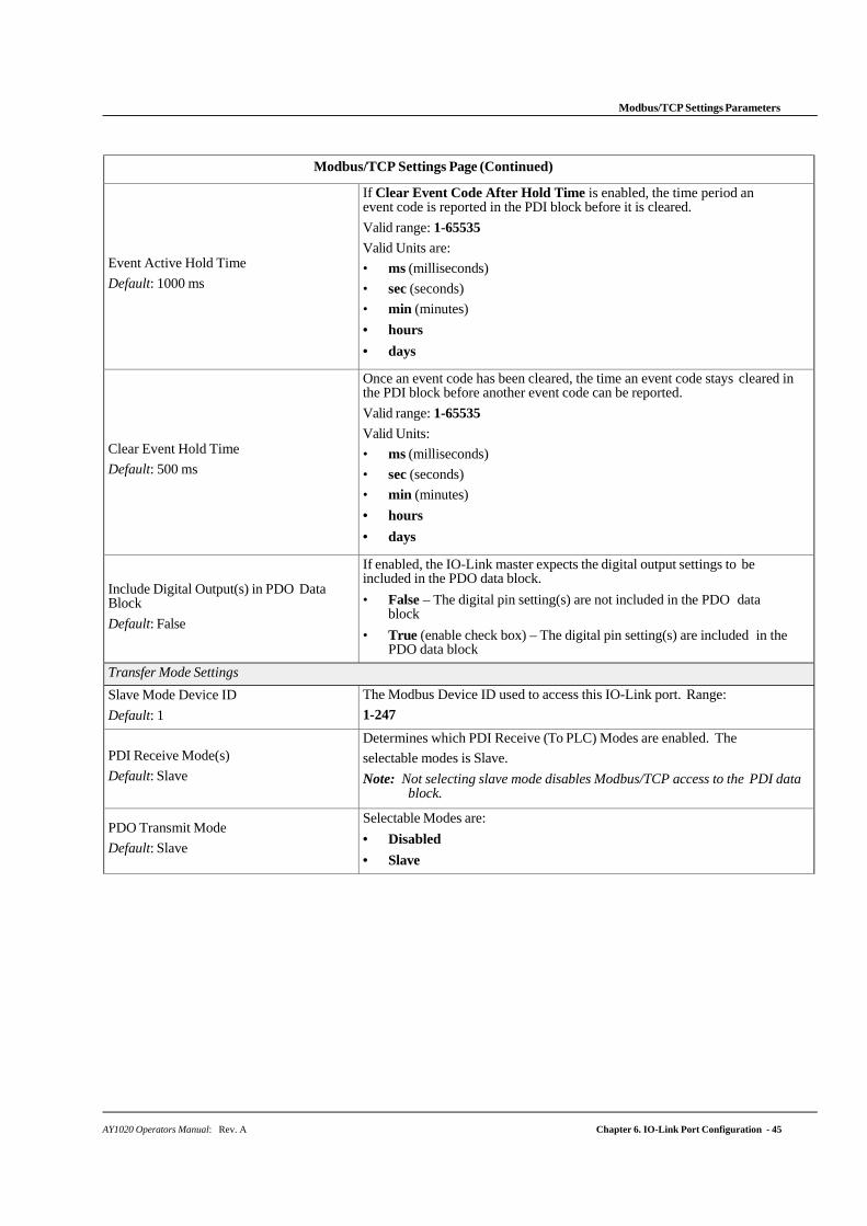
AY1020 Operators Manual: Rev. A Chapter 6. IO-Link Port Configuration - 45
Modbus/TCP Settings Parameters
Modbus/TCP Settings Page (Continued)
Event Active Hold Time
Default: 1000 ms
If Clear Event Code After Hold Time is enabled, the time period an event code is reported in the PDI block before it is cleared.
Valid range: 1-65535
Valid Units are:
• ms (milliseconds)
• sec (seconds)
• min (minutes)
• hours
• days
Clear Event Hold Time
Default: 500 ms
Once an event code has been cleared, the time an event code stays cleared in the PDI block before another event code can be reported.
Valid range: 1-65535
Valid Units:
• ms (milliseconds)
• sec (seconds)
• min (minutes)
• hours
• days
Include Digital Output(s) in PDO Data Block
Default: False
If enabled, the IO-Link master expects the digital output settings to be included in the PDO data block.
• False – The digital pin setting(s) are not included in the PDO data block
• True (enable check box) – The digital pin setting(s) are included in the PDO data block
Transfer Mode Settings
Slave Mode Device ID
Default: 1
The Modbus Device ID used to access this IO-Link port. Range:
1-247
PDI Receive Mode(s)
Default: Slave
Determines which PDI Receive (To PLC) Modes are enabled. The
selectable modes is Slave.
Note: Not selecting slave mode disables Modbus/TCP access to the PDI data block.
PDO Transmit Mode
Default: Slave
Selectable Modes are:
• Disabled
• Slave

46 - Chapter 6. IO-Link Port Configuration AY1020 Operators Manual: Rev. A
Modbus/TCP Settings Parameters
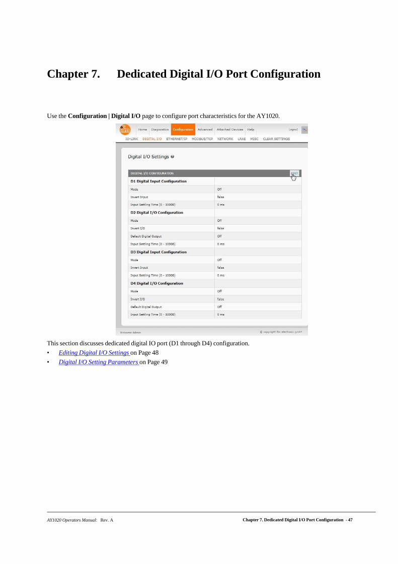
AY1020 Operators Manual: Rev. A Chapter 7. Dedicated Digital I/O Port Configuration - 47
Chapter 7. Dedicated Digital I/O Port Configuration
Use the Configuration | Digital I/O page to configure port characteristics for the AY1020.
This section discusses dedicated digital IO port (D1 through D4) configuration.
• Editing Digital I/O Settings on Page 48
• Digital I/O Setting Parameters on Page 49
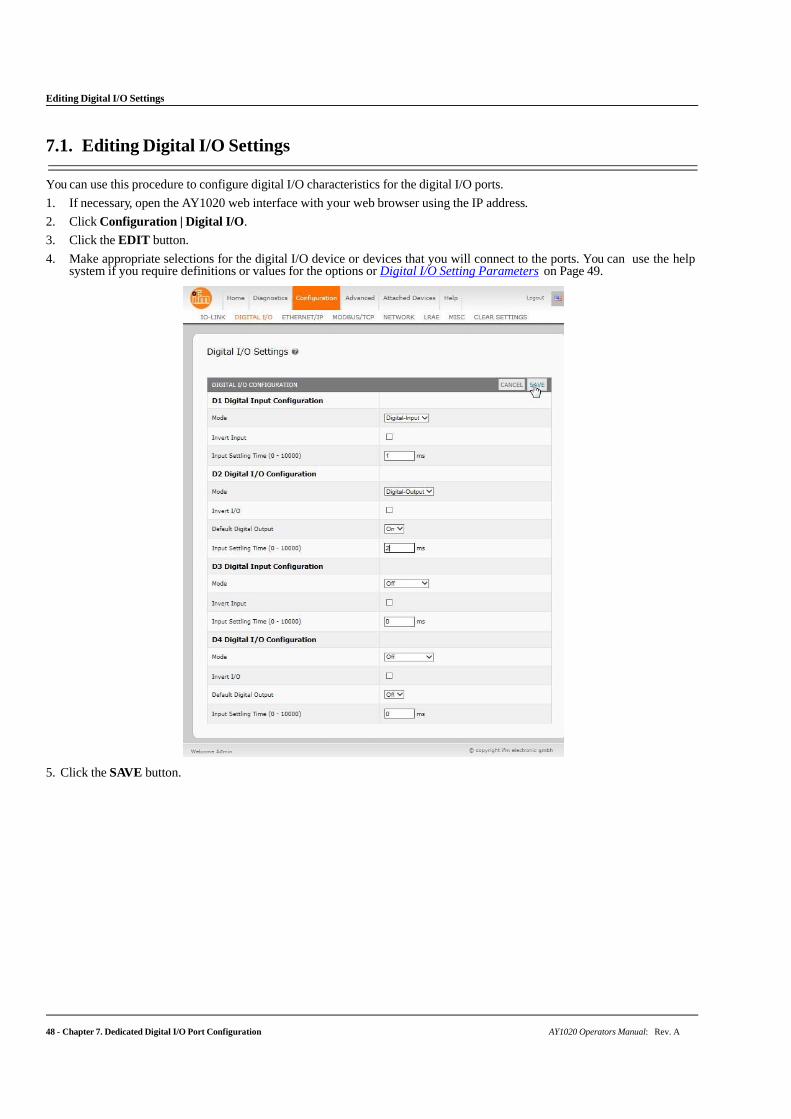
48 - Chapter 7. Dedicated Digital I/O Port Configuration AY1020 Operators Manual: Rev. A
Editing Digital I/O Settings
7.1. Editing Digital I/O Settings
You can use this procedure to configure digital I/O characteristics for the digital I/O ports.
1. If necessary, open the AY1020 web interface with your web browser using the IP address.
2. Click Configuration | Digital I/O.
3. Click the EDIT button.
4. Make appropriate selections for the digital I/O device or devices that you will connect to the ports. You can use the help system if you require definitions or values for the options or Digital I/O Setting Parameters on Page 49.
5. Click the SAVE button.
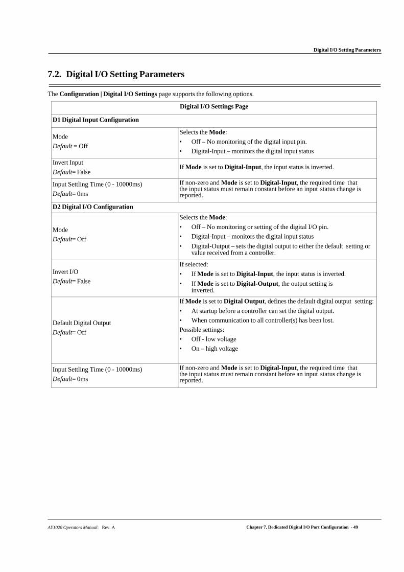
AY1020 Operators Manual: Rev. A Chapter 7. Dedicated Digital I/O Port Configuration - 49
Digital I/O Setting Parameters
7.2. Digital I/O Setting Parameters
The Configuration | Digital I/O Settings page supports the following options.
Digital I/O Settings Page
D1 Digital Input Configuration
Mode
Default = Off
Selects the Mode:
• Off – No monitoring of the digital input pin.
• Digital-Input – monitors the digital input status
Invert Input
Default= False If Mode is set to Digital-Input, the input status is inverted.
Input Settling Time (0 - 10000ms)
Default= 0ms
If non-zero and Mode is set to Digital-Input, the required time that the input status must remain constant before an input status change is reported.
D2 Digital I/O Configuration
Mode
Default= Off
Selects the Mode:
• Off – No monitoring or setting of the digital I/O pin.
• Digital-Input – monitors the digital input status
• Digital-Output – sets the digital output to either the default setting or value received from a controller.
Invert I/O
Default= False
If selected:
• If Mode is set to Digital-Input, the input status is inverted.
• If Mode is set to Digital-Output, the output setting is inverted.
Default Digital Output
Default= Off
If Mode is set to Digital Output, defines the default digital output setting:
• At startup before a controller can set the digital output.
• When communication to all controller(s) has been lost.
Possible settings:
• Off - low voltage
• On – high voltage
Input Settling Time (0 - 10000ms)
Default= 0ms
If non-zero and Mode is set to Digital-Input, the required time that the input status must remain constant before an input status change is reported.
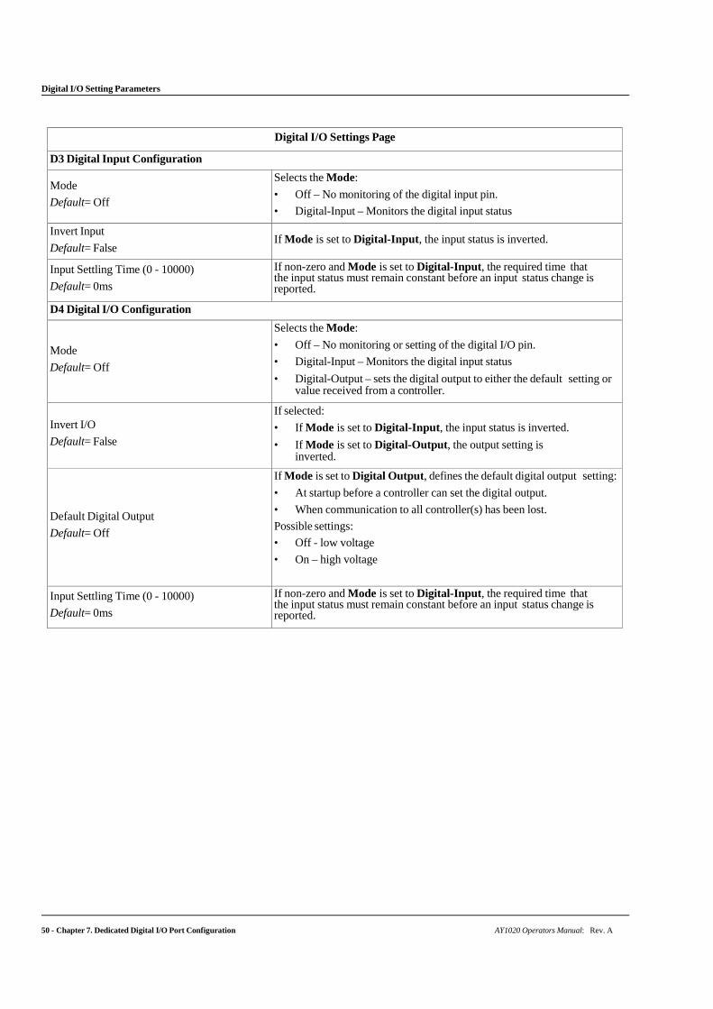
Digital I/O Setting Parameters
50 - Chapter 7. Dedicated Digital I/O Port Configuration AY1020 Operators Manual: Rev. A
Digital I/O Settings Page
D3 Digital Input Configuration
Mode
Default= Off
Selects the Mode:
• Off – No monitoring of the digital input pin.
• Digital-Input – Monitors the digital input status
Invert Input
Default= False If Mode is set to Digital-Input, the input status is inverted.
Input Settling Time (0 - 10000)
Default= 0ms
If non-zero and Mode is set to Digital-Input, the required time that the input status must remain constant before an input status change is reported.
D4 Digital I/O Configuration
Mode
Default= Off
Selects the Mode:
• Off – No monitoring or setting of the digital I/O pin.
• Digital-Input – Monitors the digital input status
• Digital-Output – sets the digital output to either the default setting or value received from a controller.
Invert I/O
Default= False
If selected:
• If Mode is set to Digital-Input, the input status is inverted.
• If Mode is set to Digital-Output, the output setting is inverted.
Default Digital Output
Default= Off
If Mode is set to Digital Output, defines the default digital output setting:
• At startup before a controller can set the digital output.
• When communication to all controller(s) has been lost.
Possible settings:
• Off - low voltage
• On – high voltage
Input Settling Time (0 - 10000)
Default= 0ms
If non-zero and Mode is set to Digital-Input, the required time that the input status must remain constant before an input status change is reported.
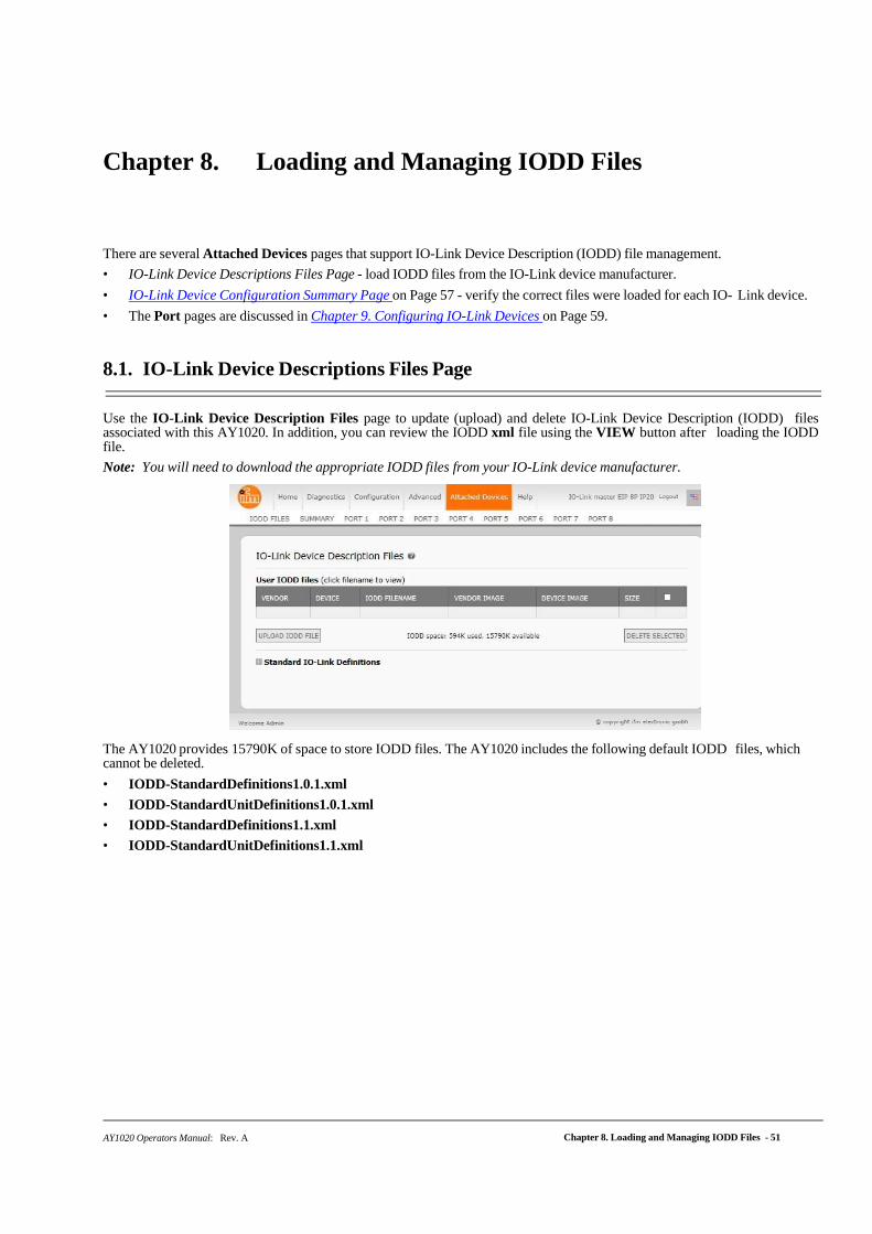
AY1020 Operators Manual: Rev. A Chapter 8. Loading and Managing IODD Files - 51
Chapter 8. Loading and Managing IODD Files
There are several Attached Devices pages that support IO-Link Device Description (IODD) file management.
• IO-Link Device Descriptions Files Page - load IODD files from the IO-Link device manufacturer.
• IO-Link Device Configuration Summary Page on Page 57 - verify the correct files were loaded for each IO- Link device.
• The Port pages are discussed in Chapter 9. Configuring IO-Link Devices on Page 59.
8.1. IO-Link Device Descriptions Files Page
Use the IO-Link Device Description Files page to update (upload) and delete IO-Link Device Description (IODD) files associated with this AY1020. In addition, you can review the IODD xml file using the VIEW button after loading the IODD file.
Note: You will need to download the appropriate IODD files from your IO-Link device manufacturer.
The AY1020 provides 15790K of space to store IODD files. The AY1020 includes the following default IODD files, which cannot be deleted.
• IODD-StandardDefinitions1.0.1.xml
• IODD-StandardUnitDefinitions1.0.1.xml
• IODD-StandardDefinitions1.1.xml
• IODD-StandardUnitDefinitions1.1.xml
Preparing IODD Files to Upload
52 - Chapter 8. Loading and Managing IODD Files AY1020 Operators Manual: Rev. A
8.1.1. Preparing IODD Files to Upload
After downloading the IODD files for the IO-Link device from the IO-Link sensor or actuator manufacturer, you may need to unzip the file and locate the appropriate xml file for the device.
• Some IODD zip files contain the xml files and supporting image files for a single product. This type of zip file can be immediately loaded onto the AY1020.
• Some IODD zip files contain the files for multiple products. If you upload this type of IODD zip file, the AY1020 loads the first xml file and the associated image files, which may or may not correspond to the IO- Link device connected to the port. If you need to zip the appropriate files, the following information may be useful:
- Unzip the package and locate the xml file needed for your IO-Link device.
- Open the xml file and search for the productID, which identifies the IO-Link device.
- Zip the xml file along with the supporting images. There are several ways to locate the supporting images:
- Locate the appropriate images using the xml file.
- Load only the xml file and the AY1020 notifies you what files are missing. Use the UPDATE feature to upload the missing images.
- Zip the xml with all of the images and the AY1020 ignores (and not upload) any unused files and notifies which files did not upload.
Note: Image files are not required for IO-Link device configuration.
Use the appropriate discussion for your IODD files.
• Uploading IODD Zip Files
• Uploading xml Files or Supporting Files on Page 54
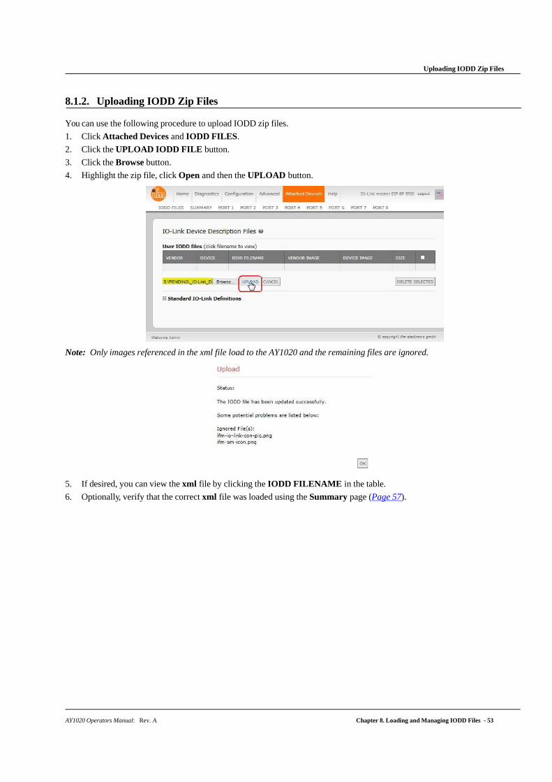
Uploading IODD Zip Files
AY1020 Operators Manual: Rev. A Chapter 8. Loading and Managing IODD Files - 53
8.1.2. Uploading IODD Zip Files
You can use the following procedure to upload IODD zip files.
1. Click Attached Devices and IODD FILES.
2. Click the UPLOAD IODD FILE button.
3. Click the Browse button.
4. Highlight the zip file, click Open and then the UPLOAD button.
Note: Only images referenced in the xml file load to the AY1020 and the remaining files are ignored.
5. If desired, you can view the xml file by clicking the IODD FILENAME in the table.
6. Optionally, verify that the correct xml file was loaded using the Summary page (Page 57).
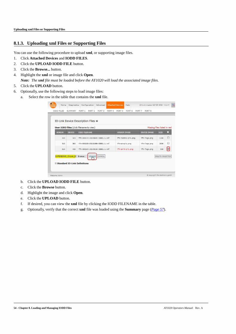
54 - Chapter 8. Loading and Managing IODD Files AY1020 Operators Manual: Rev. A
Uploading xml Files or Supporting Files
8.1.3. Uploading xml Files or Supporting Files
You can use the following procedure to upload xml, or supporting image files.
1. Click Attached Devices and IODD FILES.
2. Click the UPLOAD IODD FILE button.
3. Click the Browse... button.
4. Highlight the xml or image file and click Open.
Note: The xml file must be loaded before the AY1020 will load the associated image files.
5. Click the UPLOAD button.
6. Optionally, use the following steps to load image files:
a. Select the row in the table that contains the xml file.
b. Click the UPLOAD IODD FILE button.
c. Click the Browse button.
d. Highlight the image and click Open.
e. Click the UPLOAD button.
f. If desired, you can view the xml file by clicking the IODD FILENAME in the table.
g. Optionally, verify that the correct xml file was loaded using the Summary page (Page 57).
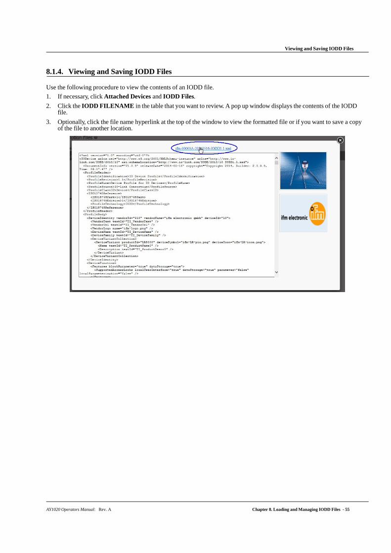
AY1020 Operators Manual: Rev. A Chapter 8. Loading and Managing IODD Files - 55
Viewing and Saving IODD Files
8.1.4. Viewing and Saving IODD Files
Use the following procedure to view the contents of an IODD file.
1. If necessary, click Attached Devices and IODD Files.
2. Click the IODD FILENAME in the table that you want to review. A pop up window displays the contents of the IODD file.
3. Optionally, click the file name hyperlink at the top of the window to view the formatted file or if you want to save a copy of the file to another location.

56 - Chapter 8. Loading and Managing IODD Files AY1020 Operators Manual: Rev. A
Deleting IODD Files
8.1.5. Deleting IODD Files
Use the following procedure to delete an IODD file set from the AY1020.
1. If necessary, click Attached Devices and IODD Files.
2. Check the corresponding row of the IODD file that you want to delete.
3. Click the DELETE SELECTED button.
4. Click CONTINUE to the Delete files? message.
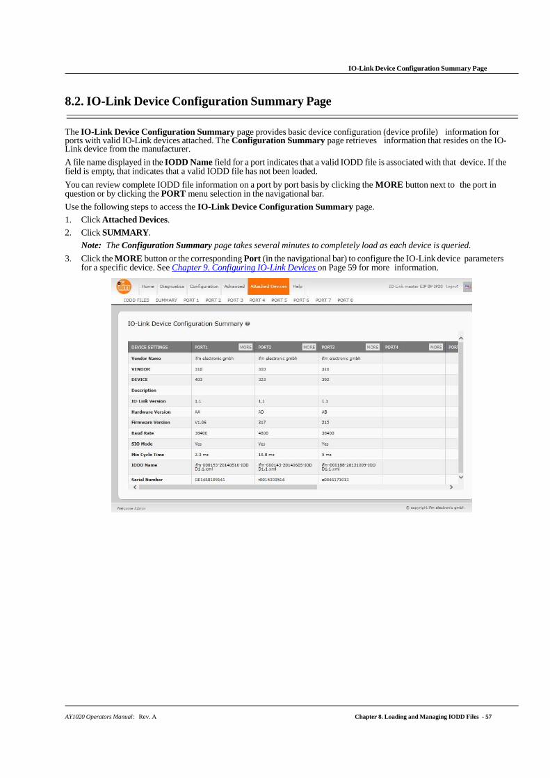
AY1020 Operators Manual: Rev. A Chapter 8. Loading and Managing IODD Files - 57
IO-Link Device Configuration Summary Page
8.2. IO-Link Device Configuration Summary Page
The IO-Link Device Configuration Summary page provides basic device configuration (device profile) information for ports with valid IO-Link devices attached. The Configuration Summary page retrieves information that resides on the IO-Link device from the manufacturer.
A file name displayed in the IODD Name field for a port indicates that a valid IODD file is associated with that device. If the field is empty, that indicates that a valid IODD file has not been loaded.
You can review complete IODD file information on a port by port basis by clicking the MORE button next to the port in question or by clicking the PORT menu selection in the navigational bar.
Use the following steps to access the IO-Link Device Configuration Summary page.
1. Click Attached Devices.
2. Click SUMMARY.
Note: The Configuration Summary page takes several minutes to completely load as each device is queried.
3. Click the MORE button or the corresponding Port (in the navigational bar) to configure the IO-Link device parameters for a specific device. See Chapter 9. Configuring IO-Link Devices on Page 59 for more information.

58 - Chapter 8. Loading and Managing IODD Files AY1020 Operators Manual: Rev. A
IO-Link Device Configuration Summary Page
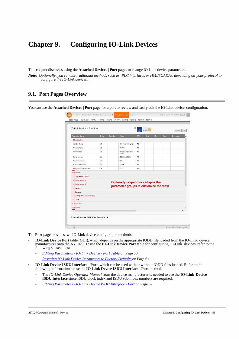
AY1020 Operators Manual: Rev. A Chapter 9. Configuring IO-Link Devices - 59
Chapter 9. Configuring IO-Link Devices
This chapter discusses using the Attached Devices | Port pages to change IO-Link device parameters.
Note: Optionally, you can use traditional methods such as: PLC interfaces or HMI/SCADAs, depending on your protocol to configure the IO-Link devices.
9.1. Port Pages Overview
You can use the Attached Devices | Port page for a port to review and easily edit the IO-Link device configuration.
The Port page provides two IO-Link device configuration methods:
• IO-Link Device Port table (GUI), which depends on the appropriate IODD file loaded from the IO-Link device manufacturer onto the AY1020. To use the IO-Link Device Port table for configuring IO-Link devices, refer to the following subsections:
- Editing Parameters - IO-Link Device - Port Table on Page 60
- Resetting IO-Link Device Parameters to Factory Defaults on Page 61
• IO-Link Device ISDU Interface - Port, which can be used with or without IODD files loaded. Refer to the following information to use the IO-Link Device ISDU Interface - Port method:
- The IO-Link Device Operator Manual from the device manufacturer is needed to use the IO-Link Device ISDU Interface since ISDU block index and ISDU sub-index numbers are required.
- Editing Parameters - IO-Link Device ISDU Interface - Port on Page 62
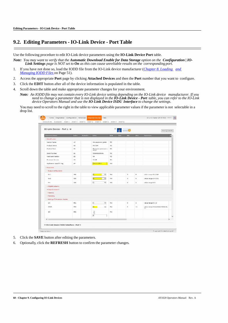
60 - Chapter 9. Configuring IO-Link Devices AY1020 Operators Manual: Rev. A
Editing Parameters - IO-Link Device - Port Table
9.2. Editing Parameters - IO-Link Device - Port Table
Use the following procedure to edit IO-Link device parameters using the IO-Link Device Port table.
Note: You may want to verify that the Automatic Download Enable for Data Storage option on the Configuration | IO-Link Settings page is NOT set to On as this can cause unreliable results on the corresponding port.
1. If you have not done so, load the IODD file from the IO-Link device manufacturer (Chapter 8. Loading and Managing IODD Files on Page 51).
2. Access the appropriate Port page by clicking Attached Devices and then the Port number that you want to configure.
3. Click the EDIT button after all of the device information is populated in the table.
4. Scroll down the table and make appropriate parameter changes for your environment.
Note: An IODD file may not contain every IO-Link device setting depending on the IO-Link device manufacturer. If you need to change a parameter that is not displayed in the IO-Link Device - Port table, you can refer to the IO-Link device Operators Manual and use the IO-Link Device ISDU Interface to change the settings.
You may need to scroll to the right in the table to view applicable parameter values if the parameter is not selectable in a drop list.
5. Click the SAVE button after editing the parameters.
6. Optionally, click the REFRESH button to confirm the parameter changes.
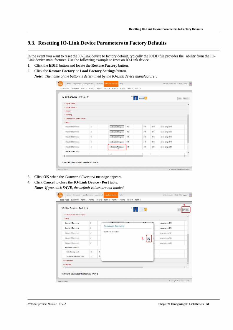
Resetting IO-Link Device Parameters to Factory Defaults
AY1020 Operators Manual: Rev. A Chapter 9. Configuring IO-Link Devices - 61
9.3. Resetting IO-Link Device Parameters to Factory Defaults
In the event you want to reset the IO-Link device to factory default, typically the IODD file provides the ability from the IO-Link device manufacturer. Use the following example to reset an IO-Link device.
1. Click the EDIT button and locate the Restore Factory button.
2. Click the Restore Factory or Load Factory Settings button.
Note: The name of the button is determined by the IO-Link device manufacturer.
3. Click OK when the Command Executed message appears.
4. Click Cancel to close the IO-Link Device - Port table.
Note: If you click SAVE, the default values are not loaded.
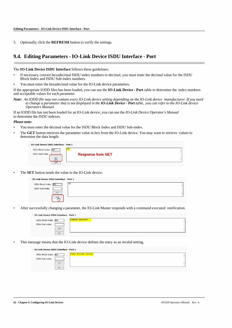
62 - Chapter 9. Configuring IO-Link Devices AY1020 Operators Manual: Rev. A
Editing Parameters - IO-Link Device ISDU Interface - Port
5. Optionally, click the REFRESH button to verify the settings.
9.4. Editing Parameters - IO-Link Device ISDU Interface - Port
The IO-Link Device ISDU Interface follows these guidelines:
• If necessary, convert hexadecimal ISDU index numbers to decimal, you must enter the decimal value for the ISDU Block Index and ISDU Sub-index numbers.
• You must enter the hexadecimal value for the IO-Link device parameters.
If the appropriate IODD files has been loaded, you can use the IO-Link Device - Port table to determine the index numbers and acceptable values for each parameter.
Note: An IODD file may not contain every IO-Link device setting depending on the IO-Link device manufacturer. If you need to change a parameter that is not displayed in the IO-Link Device - Port table, you can refer to the IO-Link device Operators Manual.
If an IODD file has not been loaded for an IO-Link device, you can use the IO-Link Device Operator's Manual to determine the ISDU indexes.
Please note:
• You must enter the decimal value for the ISDU Block Index and ISDU Sub-index.
• The GET button retrieves the parameter value in hex from the IO-Link device. You may want to retrieve values to determine the data length.
• The SET button sends the value to the IO-Link device.
• After successfully changing a parameter, the IO-Link Master responds with a command executed notification.
• This message means that the IO-Link device defines the entry as an invalid setting.
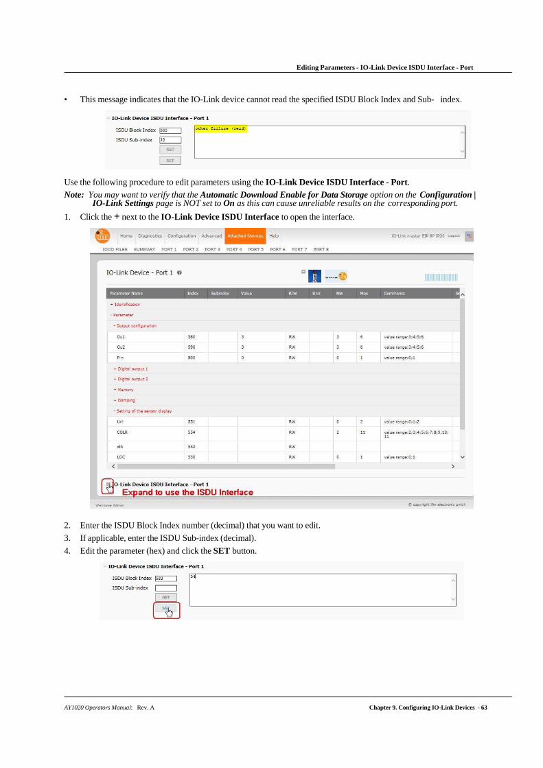
AY1020 Operators Manual: Rev. A Chapter 9. Configuring IO-Link Devices - 63
Editing Parameters - IO-Link Device ISDU Interface - Port
• This message indicates that the IO-Link device cannot read the specified ISDU Block Index and Sub- index.
Use the following procedure to edit parameters using the IO-Link Device ISDU Interface - Port.
Note: You may want to verify that the Automatic Download Enable for Data Storage option on the Configuration | IO-Link Settings page is NOT set to On as this can cause unreliable results on the corresponding port.
1. Click the + next to the IO-Link Device ISDU Interface to open the interface.
2. Enter the ISDU Block Index number (decimal) that you want to edit.
3. If applicable, enter the ISDU Sub-index (decimal).
4. Edit the parameter (hex) and click the SET button.
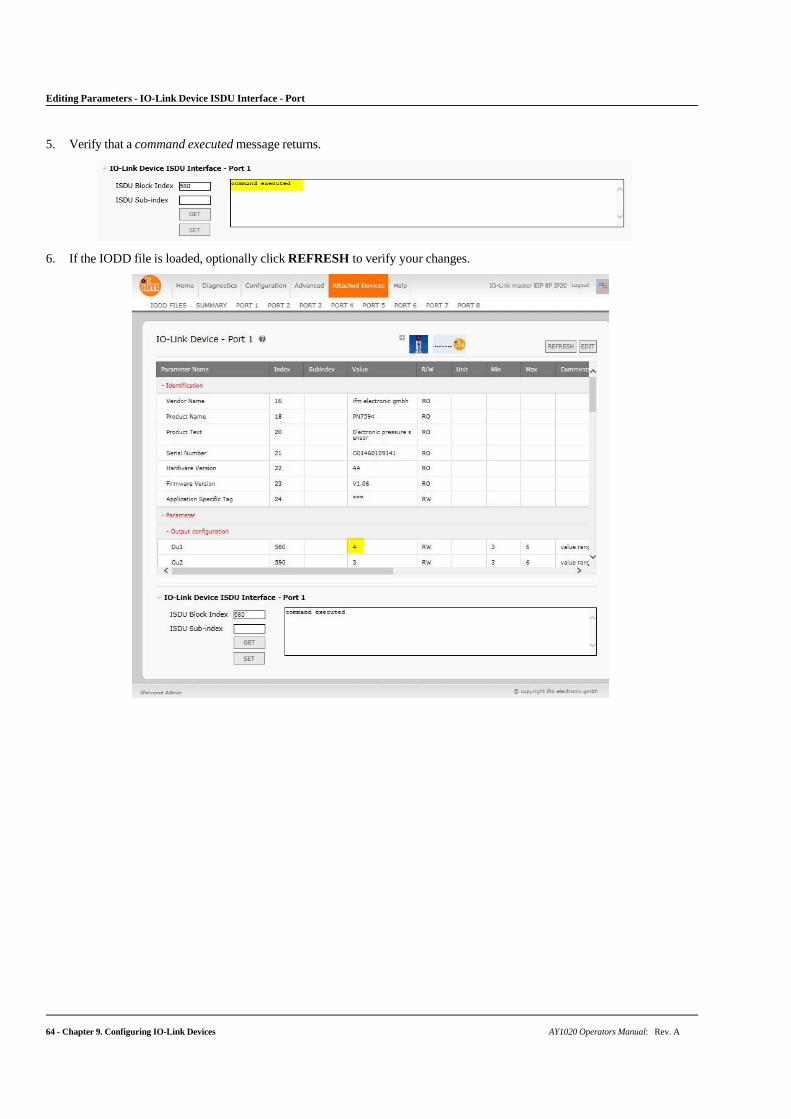
64 - Chapter 9. Configuring IO-Link Devices AY1020 Operators Manual: Rev. A
Editing Parameters - IO-Link Device ISDU Interface - Port
5. Verify that a command executed message returns.
6. If the IODD file is loaded, optionally click REFRESH to verify your changes.
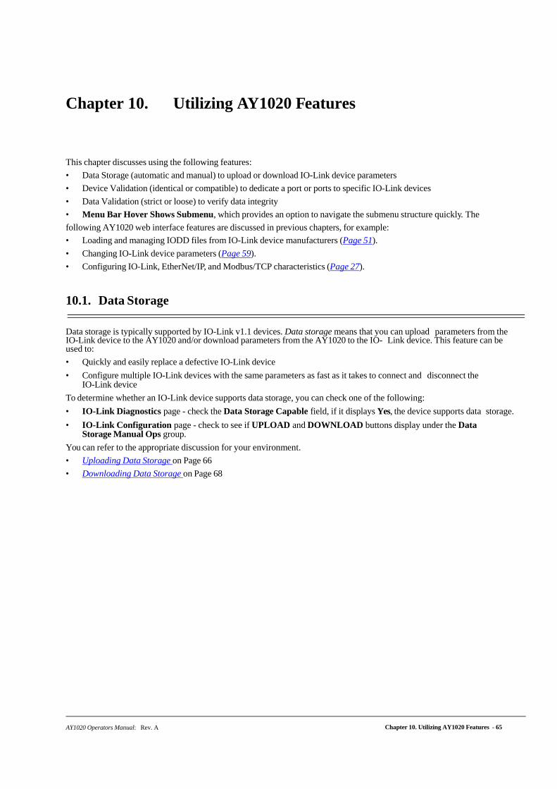
AY1020 Operators Manual: Rev. A Chapter 10. Utilizing AY1020 Features - 65
Chapter 10. Utilizing AY1020 Features
This chapter discusses using the following features:
• Data Storage (automatic and manual) to upload or download IO-Link device parameters
• Device Validation (identical or compatible) to dedicate a port or ports to specific IO-Link devices
• Data Validation (strict or loose) to verify data integrity
• Menu Bar Hover Shows Submenu, which provides an option to navigate the submenu structure quickly. The
following AY1020 web interface features are discussed in previous chapters, for example:
• Loading and managing IODD files from IO-Link device manufacturers (Page 51).
• Changing IO-Link device parameters (Page 59).
• Configuring IO-Link, EtherNet/IP, and Modbus/TCP characteristics (Page 27).
10.1. Data Storage
Data storage is typically supported by IO-Link v1.1 devices. Data storage means that you can upload parameters from the IO-Link device to the AY1020 and/or download parameters from the AY1020 to the IO- Link device. This feature can be used to:
• Quickly and easily replace a defective IO-Link device
• Configure multiple IO-Link devices with the same parameters as fast as it takes to connect and disconnect the IO-Link device
To determine whether an IO-Link device supports data storage, you can check one of the following:
• IO-Link Diagnostics page - check the Data Storage Capable field, if it displays Yes, the device supports data storage.
• IO-Link Configuration page - check to see if UPLOAD and DOWNLOAD buttons display under the Data Storage Manual Ops group.
You can refer to the appropriate discussion for your environment.
• Uploading Data Storage on Page 66
• Downloading Data Storage on Page 68
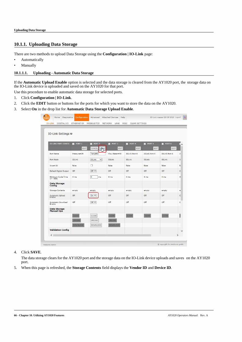
66 - Chapter 10. Utilizing AY1020 Features AY1020 Operators Manual: Rev. A
Uploading Data Storage
10.1.1. Uploading Data Storage
There are two methods to upload Data Storage using the Configuration | IO-Link page:
• Automatically
• Manually
10.1.1.1. Uploading - Automatic Data Storage
If the Automatic Upload Enable option is selected and the data storage is cleared from the AY1020 port, the storage data on the IO-Link device is uploaded and saved on the AY1020 for that port.
Use this procedure to enable automatic data storage for selected ports.
1. Click Configuration | IO-Link.
2. Click the EDIT button or buttons for the ports for which you want to store the data on the AY1020.
3. Select On in the drop list for Automatic Data Storage Upload Enable.
4. Click SAVE.
The data storage clears for the AY1020 port and the storage data on the IO-Link device uploads and saves on the AY1020 port.
5. When this page is refreshed, the Storage Contents field displays the Vendor ID and Device ID.
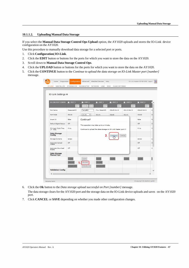
AY1020 Operators Manual: Rev. A Chapter 10. Utilizing AY1020 Features - 67
Uploading Manual Data Storage
10.1.1.2. Uploading Manual Data Storage
If you select the Manual Data Storage Control Ops Upload option, the AY1020 uploads and stores the IO-Link device configuration on the AY1020.
Use this procedure to manually download data storage for a selected port or ports.
1. Click Configuration| IO-Link.
2. Click the EDIT button or buttons for the ports for which you want to store the data on the AY1020.
3. Scroll down to Manual Data Storage Control Ops.
4. Click the UPLOAD button or buttons for the ports for which you want to store the data on the AY1020.
5. Click the CONTINUE button to the Continue to upload the data storage on IO-Link Master port [number] message.
6. Click the Ok button to the Data storage upload successful on Port [number] message.
The data storage clears for the AY1020 port and the storage data on the IO-Link device uploads and saves on the AY1020 port.
7. Click CANCEL or SAVE depending on whether you made other configuration changes.
68 - Chapter 10. Utilizing AY1020 Features AY1020 Operators Manual: Rev. A
Downloading Data Storage
10.1.2. Downloading Data Storage
There are two methods to download Data Storage:
• Automatically
• Manually
10.1.2.1. Downloading- Automatic Data Storage
If you select the Automatic Download Enable option, the data stored on the AY1020 port is downloaded to the IO-Link device if:
• This option is selected.
• The data stored on the AY1020 port contains the same Vendor ID and Product ID as the IO-Link device connected to the port.
• The data stored on the AY1020 port is different than that of the IO-Link device. Use this
procedure to enable automatic data storage for selected ports.
1. Click Configuration | IO-Link Settings.
2. Click the EDIT button or buttons for the ports for which you want to store the data on the AY1020.
3. Select On in the drop list for Automatic Data Storage Download Enable.
4. Click SAVE.
When an IO-Link device, which is the same model with different parameters is attached to the port, data storage is automatically downloaded from the AY1020 to the IO-Link device.
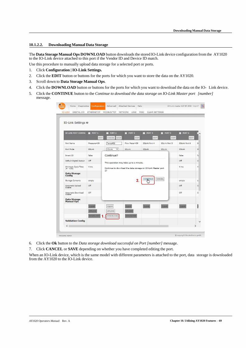
AY1020 Operators Manual: Rev. A Chapter 10. Utilizing AY1020 Features - 69
Downloading Manual Data Storage
10.1.2.2. Downloading Manual Data Storage
The Data Storage Manual Ops DOWNLOAD button downloads the stored IO-Link device configuration from the AY1020 to the IO-Link device attached to this port if the Vendor ID and Device ID match.
Use this procedure to manually upload data storage for a selected port or ports.
1. Click Configuration | IO-Link Settings.
2. Click the EDIT button or buttons for the ports for which you want to store the data on the AY1020.
3. Scroll down to Data Storage Manual Ops.
4. Click the DOWNLOAD button or buttons for the ports for which you want to download the data on the IO- Link device.
5. Click the CONTINUE button to the Continue to download the data storage on IO-Link Master port [number] message.
6. Click the Ok button to the Data storage download successful on Port [number] message.
7. Click CANCEL or SAVE depending on whether you have completed editing the port.
When an IO-Link device, which is the same model with different parameters is attached to the port, data storage is downloaded from the AY1020 to the IO-Link device.
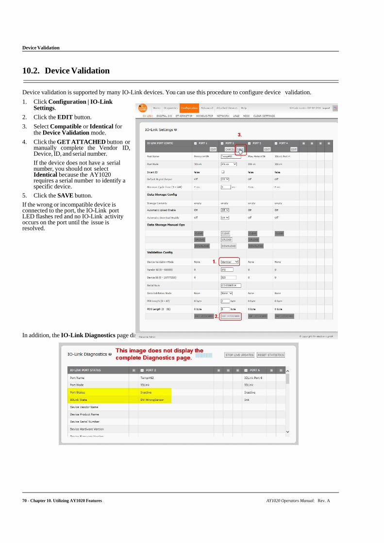
Device Validation
70 - Chapter 10. Utilizing AY1020 Features AY1020 Operators Manual: Rev. A
10.2. Device Validation
Device validation is supported by many IO-Link devices. You can use this procedure to configure device validation.
1. Click Configuration | IO-Link Settings.
2. Click the EDIT button.
3. Select Compatible or Identical for the Device Validation mode.
4. Click the GET ATTACHED button or manually complete the Vendor ID, Device, ID, and serial number.
If the device does not have a serial number, you should not select Identical because the AY1020 requires a serial number to identify a specific device.
5. Click the SAVE button.
If the wrong or incompatible device is connected to the port, the IO-Link port LED flashes red and no IO-Link activity occurs on the port until the issue is resolved.
In addition, the IO-Link Diagnostics page displays the following information.
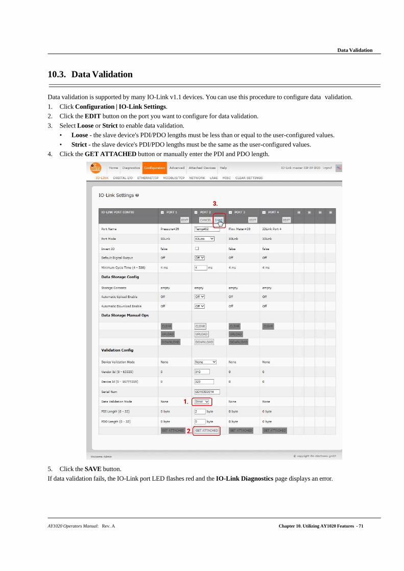
Data Validation
AY1020 Operators Manual: Rev. A Chapter 10. Utilizing AY1020 Features - 71
10.3. Data Validation
Data validation is supported by many IO-Link v1.1 devices. You can use this procedure to configure data validation.
1. Click Configuration | IO-Link Settings.
2. Click the EDIT button on the port you want to configure for data validation.
3. Select Loose or Strict to enable data validation.
• Loose - the slave device's PDI/PDO lengths must be less than or equal to the user-configured values.
• Strict - the slave device's PDI/PDO lengths must be the same as the user-configured values.
4. Click the GET ATTACHED button or manually enter the PDI and PDO length.
5. Click the SAVE button.
If data validation fails, the IO-Link port LED flashes red and the IO-Link Diagnostics page displays an error.
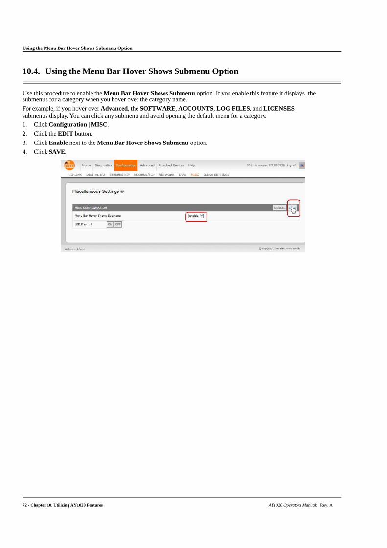
Using the Menu Bar Hover Shows Submenu Option
72 - Chapter 10. Utilizing AY1020 Features AY1020 Operators Manual: Rev. A
10.4. Using the Menu Bar Hover Shows Submenu Option
Use this procedure to enable the Menu Bar Hover Shows Submenu option. If you enable this feature it displays the submenus for a category when you hover over the category name.
For example, if you hover over Advanced, the SOFTWARE, ACCOUNTS, LOG FILES, and LICENSES submenus display. You can click any submenu and avoid opening the default menu for a category.
1. Click Configuration | MISC.
2. Click the EDIT button.
3. Click Enable next to the Menu Bar Hover Shows Submenu option.
4. Click SAVE.

AY1020 Operators Manual: Rev. A Chapter 11. Using the Diagnostics Pages - 73
Chapter 11. Using the Diagnostics Pages
This chapter provides information about the following Diagnostics pages.
• IO-Link Port Diagnostics
• Digital I/O Diagnostics on Page 77
• EtherNet/IP Diagnostics on Page 78
• Modbus/TCP Diagnostics on Page 82
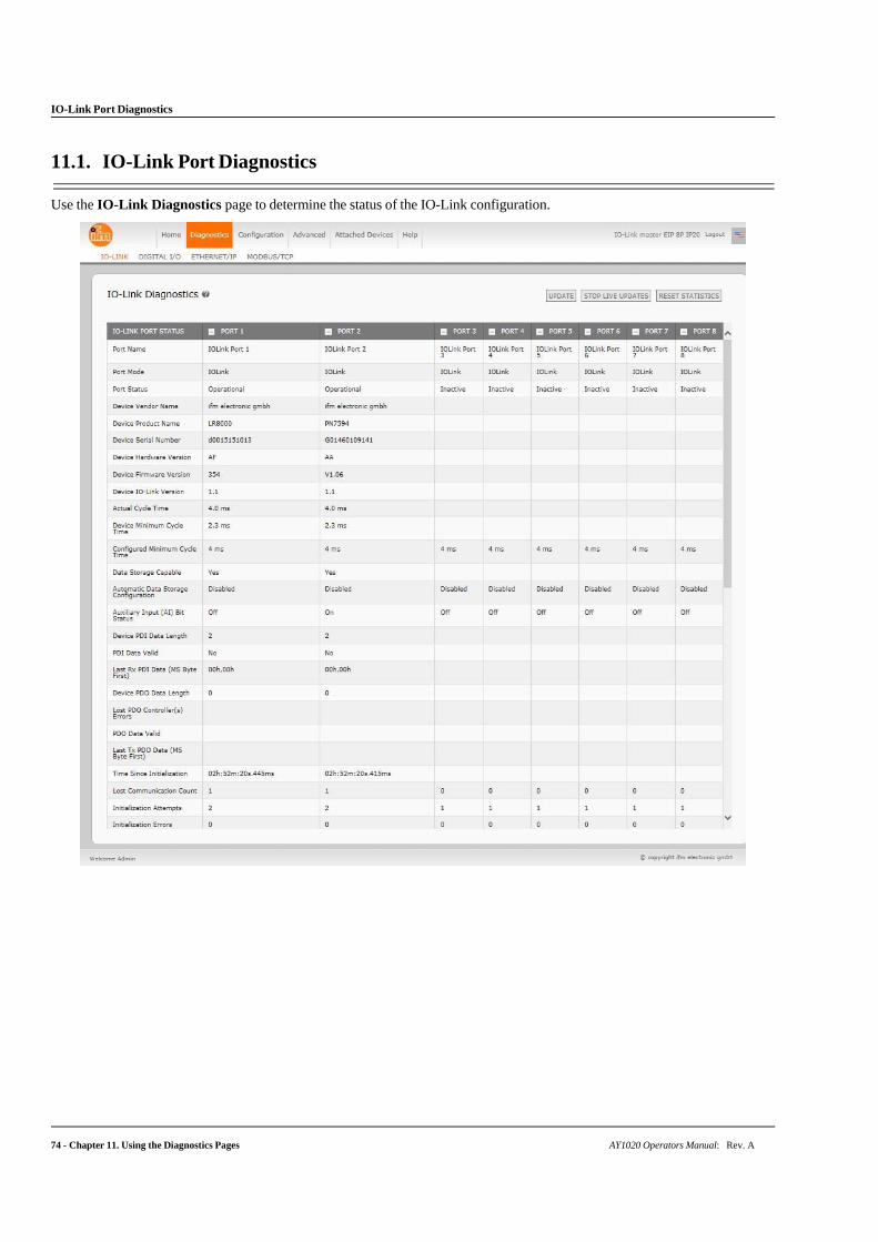
IO-Link Port Diagnostics
74 - Chapter 11. Using the Diagnostics Pages AY1020 Operators Manual: Rev. A
11.1. IO-Link Port Diagnostics
Use the IO-Link Diagnostics page to determine the status of the IO-Link configuration.
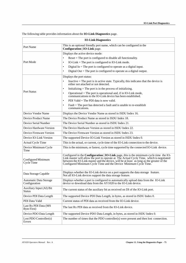
IO-Link Port Diagnostics
AY1020 Operators Manual: Rev. A Chapter 11. Using the Diagnostics Pages - 75
The following table provides information about the IO-Link Diagnostics page.
IO-Link Diagnostics
Port Name This is an optional friendly port name, which can be configured in the Configuration | IO-Link page.
Port Mode
Displays the active device mode:
• Reset = The port is configured to disable all functionality.
• IO-Link = The port is configured to IO-Link mode.
• Digital In = The port is configured to operate as a digital input.
• Digital Out = The port is configured to operate as a digital output.
Port Status
Displays the port status:
• Inactive = The port is in active state. Typically, this indicates that the device is either not attached or not detected.
• Initializing = The port is in the process of initializing.
• Operational = The port is operational and, if in IO-Link mode, communications to the IO-Link device has been established.
• PDI Valid = The PDI data is now valid.
• Fault = The port has detected a fault and is unable to re-establish communications.
Device Vendor Name Displays the Device Vendor Name as stored in ISDU Index 16.
Device Product Name The Device Product Name as stored in ISDU Index 18.
Device Serial Number The Device Serial Number as stored in ISDU Index 21.
Device Hardware Version The Device Hardware Version as stored in ISDU Index 22.
Device Firmware Version The Device Firmware Version as stored in ISDU Index 23.
Device IO-Link Version The supported Device IO-Link Version as stored in ISDU Index 0.
Actual Cycle Time This is the actual, or current, cycle time of the IO-Link connection to the device.
Device Minimum Cycle Time
This is the minimum, or fastest, cycle time supported by the connected IO-Link device.
Configured Minimum Cycle Time
Configured in the Configuration | IO-Link page, this is the minimum cycle time the IO-Link master will allow the port to operate at. The Actual Cycle Time, which is negotiated between the IO-Link master and the device, will be at least as long as the greater of the Configured Minimum Cycle Time and the Device Minimum Cycle Time.
Data Storage Capable Displays whether the IO-Link device on a port supports the data storage feature. Not all IO-Link devices support the data storage feature.
Automatic Data Storage Configuration
Displays whether a port is configured to automatically upload data from the IO-Link device or download data from the AY1020 to the IO-Link device.
Auxiliary Input (AI) Bit Status The current status of the auxiliary bit as received on DI of the IO-Link port.
Device PDI Data Length The supported Device PDI Data Length, in bytes, as stored in ISDU Index 0.
PDI Data Valid Current status of PDI data as received from the IO-Link device.
Last Rx PDI Data (MS Byte First) The last Rx PDI data as received from the IO-Link device.
Device PDO Data Length The supported Device PDO Data Length, in bytes, as stored in ISDU Index 0.
Lost PDO Controller(s) Errors
The number of times that the PDO controller(s) were present and then lost connection.
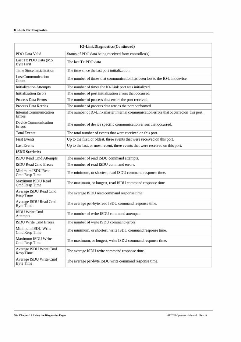
IO-Link Port Diagnostics
76 - Chapter 11. Using the Diagnostics Pages AY1020 Operators Manual: Rev. A
IO-Link Diagnostics (Continued)
PDO Data Valid Status of PDO data being received from controller(s).
Last Tx PDO Data (MS Byte First The last Tx PDO data.
Time Since Initialization The time since the last port initialization.
Lost Communication Count The number of times that communication has been lost to the IO-Link device.
Initialization Attempts The number of times the IO-Link port was initialized.
Initialization Errors The number of port initialization errors that occurred.
Process Data Errors The number of process data errors the port received.
Process Data Retries The number of process data retries the port performed.
Internal Communication Errors
The number of IO-Link master internal communication errors that occurred on this port.
Device Communication Errors The number of device specific communication errors that occurred.
Total Events The total number of events that were received on this port.
First Events Up to the first, or oldest, three events that were received on this port.
Last Events Up to the last, or most recent, three events that were received on this port.
ISDU Statistics
ISDU Read Cmd Attempts The number of read ISDU command attempts.
ISDU Read Cmd Errors The number of read ISDU command errors.
Minimum ISDU Read Cmd Resp Time The minimum, or shortest, read ISDU command response time.
Maximum ISDU Read Cmd Resp Time The maximum, or longest, read ISDU command response time.
Average ISDU Read Cmd Resp Time The average ISDU read command response time.
Average ISDU Read Cmd Byte Time The average per-byte read ISDU command response time.
ISDU Write Cmd Attempts The number of write ISDU command attempts.
ISDU Write Cmd Errors The number of write ISDU command errors.
Minimum ISDU Write Cmd Resp Time The minimum, or shortest, write ISDU command response time.
Maximum ISDU Write Cmd Resp Time The maximum, or longest, write ISDU command response time.
Average ISDU Write Cmd Resp Time The average ISDU write command response time.
Average ISDU Write Cmd Byte Time The average per-byte ISDU write command response time.
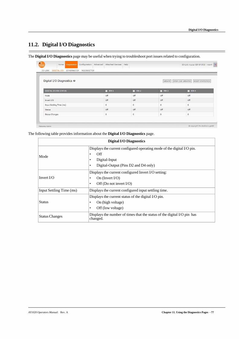
AY1020 Operators Manual: Rev. A Chapter 11. Using the Diagnostics Pages - 77
Digital I/O Diagnostics
11.2. Digital I/O Diagnostics
The Digital I/O Diagnostics page may be useful when trying to troubleshoot port issues related to configuration.
The following table provides information about the Digital I/O Diagnostics page.
Digital I/O Diagnostics
Mode
Displays the current configured operating mode of the digital I/O pin.
• Off
• Digital-Input
• Digital-Output (Pins D2 and D4 only)
Invert I/O
Displays the current configured Invert I/O setting:
• On (Invert I/O)
• Off (Do not invert I/O)
Input Settling Time (ms) Displays the current configured input settling time.
Status
Displays the current status of the digital I/O pin.
• On (high voltage)
• Off (low voltage)
Status Changes Displays the number of times that the status of the digital I/O pin has changed.
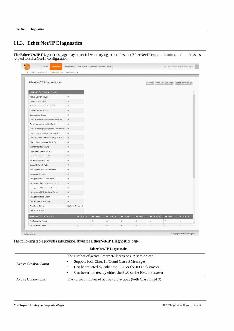
78 - Chapter 11. Using the Diagnostics Pages AY1020 Operators Manual: Rev. A
EtherNet/IP Diagnostics
11.3. EtherNet/IP Diagnostics
The EtherNet/IP Diagnostics page may be useful when trying to troubleshoot EtherNet/IP communications and port issues related to EtherNet/IP configuration.
The following table provides information about the EtherNet/IP Diagnostics page.
EtherNet/IP Diagnostics
Active Session Count
The number of active Ethernet/IP sessions. A session can:
• Support both Class 1 I/O and Class 3 Messages
• Can be initiated by either the PLC or the IO-Link master
• Can be terminated by either the PLC or the IO-Link master
Active Connections The current number of active connections (both Class 1 and 3).
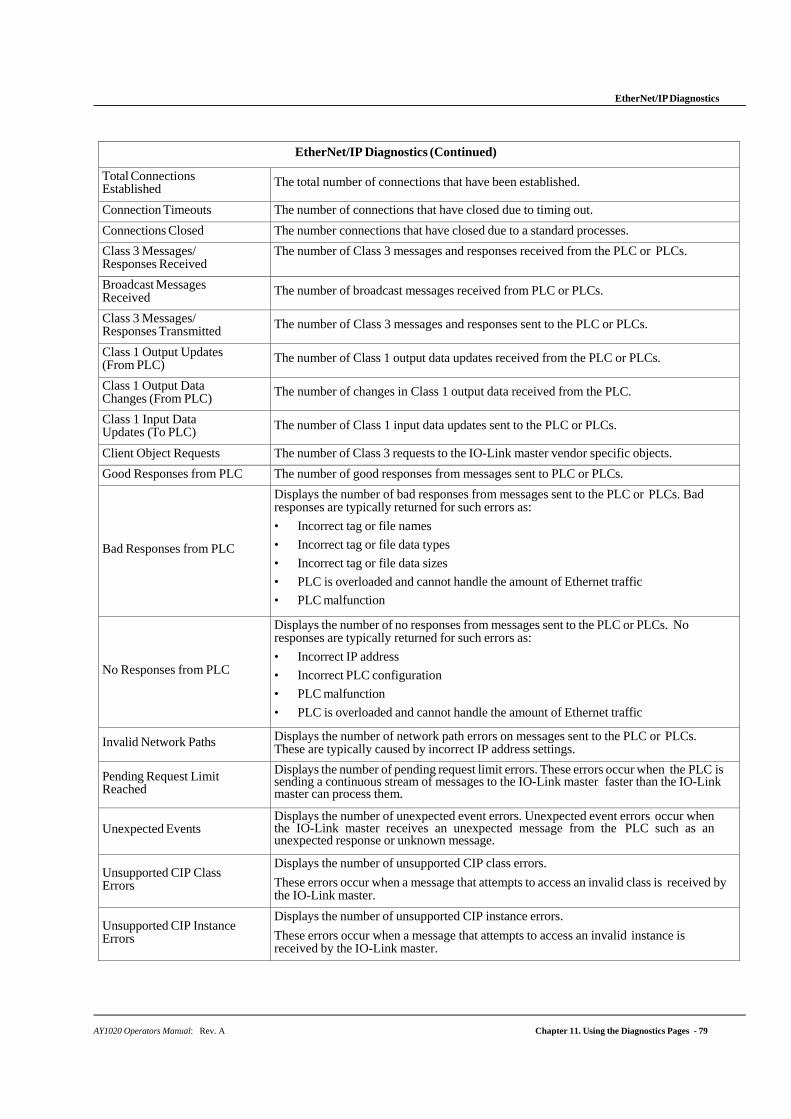
AY1020 Operators Manual: Rev. A Chapter 11. Using the Diagnostics Pages - 79
EtherNet/IP Diagnostics
EtherNet/IP Diagnostics (Continued)
Total Connections Established The total number of connections that have been established.
Connection Timeouts The number of connections that have closed due to timing out.
Connections Closed The number connections that have closed due to a standard processes.
Class 3 Messages/ Responses Received
The number of Class 3 messages and responses received from the PLC or PLCs.
Broadcast Messages Received The number of broadcast messages received from PLC or PLCs.
Class 3 Messages/ Responses Transmitted The number of Class 3 messages and responses sent to the PLC or PLCs.
Class 1 Output Updates (From PLC) The number of Class 1 output data updates received from the PLC or PLCs.
Class 1 Output Data Changes (From PLC) The number of changes in Class 1 output data received from the PLC.
Class 1 Input Data Updates (To PLC) The number of Class 1 input data updates sent to the PLC or PLCs.
Client Object Requests The number of Class 3 requests to the IO-Link master vendor specific objects.
Good Responses from PLC The number of good responses from messages sent to PLC or PLCs.
Bad Responses from PLC
Displays the number of bad responses from messages sent to the PLC or PLCs. Bad responses are typically returned for such errors as:
• Incorrect tag or file names
• Incorrect tag or file data types
• Incorrect tag or file data sizes
• PLC is overloaded and cannot handle the amount of Ethernet traffic
• PLC malfunction
No Responses from PLC
Displays the number of no responses from messages sent to the PLC or PLCs. No responses are typically returned for such errors as:
• Incorrect IP address
• Incorrect PLC configuration
• PLC malfunction
• PLC is overloaded and cannot handle the amount of Ethernet traffic
Invalid Network Paths Displays the number of network path errors on messages sent to the PLC or PLCs. These are typically caused by incorrect IP address settings.
Pending Request Limit Reached
Displays the number of pending request limit errors. These errors occur when the PLC is sending a continuous stream of messages to the IO-Link master faster than the IO-Link master can process them.
Unexpected Events
Displays the number of unexpected event errors. Unexpected event errors occur when the IO-Link master receives an unexpected message from the PLC such as an unexpected response or unknown message.
Unsupported CIP Class Errors
Displays the number of unsupported CIP class errors.
These errors occur when a message that attempts to access an invalid class is received by the IO-Link master.
Unsupported CIP Instance Errors
Displays the number of unsupported CIP instance errors.
These errors occur when a message that attempts to access an invalid instance is received by the IO-Link master.
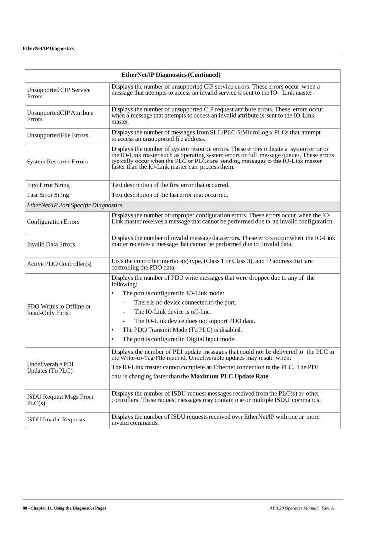
EtherNet/IP Diagnostics
80 - Chapter 11. Using the Diagnostics Pages AY1020 Operators Manual: Rev. A
EtherNet/IP Diagnostics (Continued)
Unsupported CIP Service Errors
Displays the number of unsupported CIP service errors. These errors occur when a message that attempts to access an invalid service is sent to the IO- Link master.
Unsupported CIP Attribute Errors
Displays the number of unsupported CIP request attribute errors. These errors occur when a message that attempts to access an invalid attribute is sent to the IO-Link master.
Unsupported File Errors Displays the number of messages from SLC/PLC-5/MicroLogix PLCs that attempt to access an unsupported file address.
System Resource Errors
Displays the number of system resource errors. These errors indicate a system error on the IO-Link master such as operating system errors or full message queues. These errors typically occur when the PLC or PLCs are sending messages to the IO-Link master faster than the IO-Link master can process them.
First Error String Text description of the first error that occurred.
Last Error String Text description of the last error that occurred.
EtherNet/IP Port Specific Diagnostics
Configuration Errors Displays the number of improper configuration errors. These errors occur when the IO-Link master receives a message that cannot be performed due to an invalid configuration.
Invalid Data Errors
Displays the number of invalid message data errors. These errors occur when the IO-Link master receives a message that cannot be performed due to invalid data.
Active PDO Controller(s) Lists the controller interface(s) type, (Class 1 or Class 3), and IP address that are controlling the PDO data.
PDO Writes to Offline or Read-Only Ports
Displays the number of PDO write messages that were dropped due to any of the following:
• The port is configured in IO-Link mode:
- There is no device connected to the port.
- The IO-Link device is off-line.
- The IO-Link device does not support PDO data.
• The PDO Transmit Mode (To PLC) is disabled.
• The port is configured in Digital Input mode.
Undeliverable PDI Updates (To PLC)
Displays the number of PDI update messages that could not be delivered to the PLC in the Write-to-Tag/File method. Undeliverable updates may result when:
The IO-Link master cannot complete an Ethernet connection to the PLC. The PDI
data is changing faster than the Maximum PLC Update Rate.
ISDU Request Msgs From PLC(s)
Displays the number of ISDU request messages received from the PLC(s) or other controllers. These request messages may contain one or multiple ISDU commands.
ISDU Invalid Requests Displays the number of ISDU requests received over EtherNet/IP with one or more invalid commands.
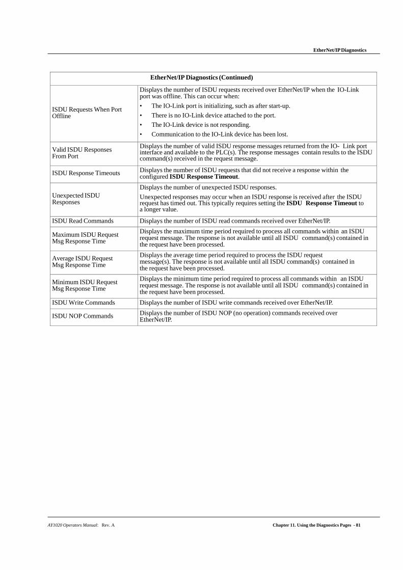
EtherNet/IP Diagnostics
AY1020 Operators Manual: Rev. A Chapter 11. Using the Diagnostics Pages - 81
EtherNet/IP Diagnostics (Continued)
ISDU Requests When Port Offline
Displays the number of ISDU requests received over EtherNet/IP when the IO-Link port was offline. This can occur when:
• The IO-Link port is initializing, such as after start-up.
• There is no IO-Link device attached to the port.
• The IO-Link device is not responding.
• Communication to the IO-Link device has been lost.
Valid ISDU Responses From Port
Displays the number of valid ISDU response messages returned from the IO- Link port interface and available to the PLC(s). The response messages contain results to the ISDU command(s) received in the request message.
ISDU Response Timeouts Displays the number of ISDU requests that did not receive a response within the configured ISDU Response Timeout.
Unexpected ISDU Responses
Displays the number of unexpected ISDU responses.
Unexpected responses may occur when an ISDU response is received after the ISDU request has timed out. This typically requires setting the ISDU Response Timeout to a longer value.
ISDU Read Commands Displays the number of ISDU read commands received over EtherNet/IP.
Maximum ISDU Request Msg Response Time
Displays the maximum time period required to process all commands within an ISDU request message. The response is not available until all ISDU command(s) contained in the request have been processed.
Average ISDU Request Msg Response Time
Displays the average time period required to process the ISDU request message(s). The response is not available until all ISDU command(s) contained in the request have been processed.
Minimum ISDU Request Msg Response Time
Displays the minimum time period required to process all commands within an ISDU request message. The response is not available until all ISDU command(s) contained in the request have been processed.
ISDU Write Commands Displays the number of ISDU write commands received over EtherNet/IP.
ISDU NOP Commands Displays the number of ISDU NOP (no operation) commands received over EtherNet/IP.
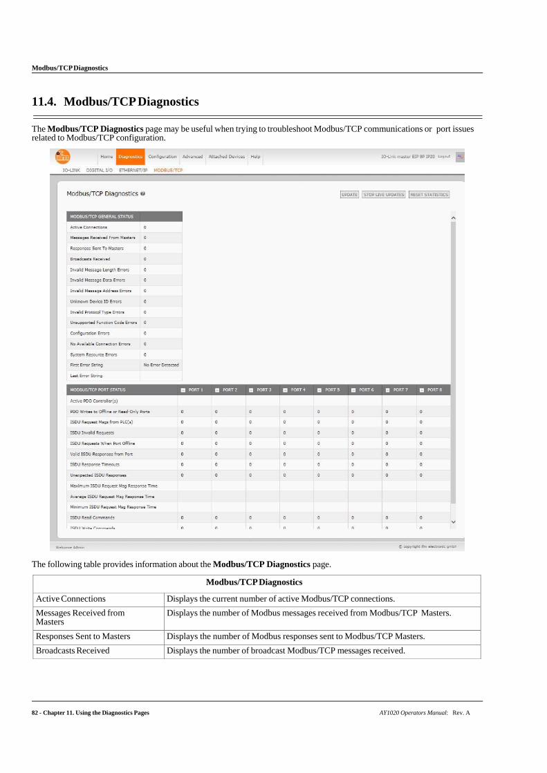
Modbus/TCP Diagnostics
82 - Chapter 11. Using the Diagnostics Pages AY1020 Operators Manual: Rev. A
11.4. Modbus/TCP Diagnostics
The Modbus/TCP Diagnostics page may be useful when trying to troubleshoot Modbus/TCP communications or port issues related to Modbus/TCP configuration.
The following table provides information about the Modbus/TCP Diagnostics page.
Modbus/TCP Diagnostics
Active Connections Displays the current number of active Modbus/TCP connections.
Messages Received from Masters
Displays the number of Modbus messages received from Modbus/TCP Masters.
Responses Sent to Masters Displays the number of Modbus responses sent to Modbus/TCP Masters.
Broadcasts Received Displays the number of broadcast Modbus/TCP messages received.
Modbus/TCP Diagnostics
AY1020 Operators Manual: Rev. A Chapter 11. Using the Diagnostics Pages - 83
Modbus/TCP Diagnostics (Continued)
Invalid Message Length Errors
Displays the number of Modbus messages received with incorrect length fields.
Invalid Message Data Errors
Displays the number of invalid message data errors. These errors occur when the IO-Link master receives a message that cannot be performed due to invalid data.
Invalid Message Address Errors
Displays the number of invalid message address errors. These errors occur when the IO-Link master receives a message that cannot be performed due to an invalid address.
Unknown Device ID Errors
Displays the number of unknown device ID errors. These errors occur when the IO-Link master receives a message that is addressed to a device ID other than the configured Slave Mode Device ID.
Invalid Protocol Type Errors
Displays the number of invalid message protocol type errors. These errors occur when the IO-Link master receives a Modbus/TCP message that specifies a non-Modbus protocol.
Unsupported Function Code Errors
Displays the number of invalid Modbus function code errors. These errors occur when the IO-Link master receives a message that cannot be performed due to an unsupported Modbus function code.
Configuration Errors
Displays the number of improper configuration errors. These errors occur when the IO-Link master receives a message that cannot be performed due to an invalid configuration.
No Available Connection Errors
Displays the number of Modbus/TCP connection attempts that were rejected due to no available connections. This occurs when the number of Modbus/TCP connections has reached the limit.
System Resource Errors
Displays the number of system resource errors. These errors indicate a system error on the IO-Link such as operating system errors or full message queues. These errors typically occur when the PLC(s) are sending messages to the IO-Link master faster than the IO-Link master can process them.
First Error String Text description of the first error that occurred.
Last Error String Text description of the last error that occurred.
Modbus/TCP Port Specific Diagnostics
Active PDO Controller(s) Lists the controller interface(s) type, (Class 1 or Class 3), and IP address that are controlling the PDO data.
PDO Writes to Offline or Read-Only Ports
Displays the number of PDO write messages that were dropped due to any of the following:
• The port is configured in IO-Link mode:
- There is no device connected to the port.
- The IO-Link device is off-line.
- The IO-Link device does not support PDO data.
• The PDO Transmit Mode (To PLC) is disabled.
• The port is configured in Digital Input mode.
ISDU Request Msgs From PLC(s)
Displays the number of ISDU request messages received from the PLC(s) or other controllers. These request messages may contain one or multiple ISDU commands.
ISDU Invalid Requests Displays the number of ISDU requests received over Modbus/TCP with one or more invalid commands.
Modbus/TCP Diagnostics
84 - Chapter 11. Using the Diagnostics Pages AY1020 Operators Manual: Rev. A
Modbus/TCP Diagnostics (Continued)
ISDU Requests When Port Offline
Displays the number of ISDU requests received over Modbus/TCP when the IO-Link port was offline. This can occur when:
• The IO-Link port is initializing, such as after start-up.
• There is no IO-Link device attached to the port.
• The IO-Link device is not responding.
• Communication to the IO-Link device has been lost.
Valid ISDU Responses From Port
Displays the number of valid ISDU response messages returned from the IO-Link port interface and available to the PLC(s). The response messages contain results to the ISDU command(s) received in the request message.
ISDU Response Timeouts Displays the number of ISDU requests that did not receive a response within the configured ISDU Response Timeout.
Unexpected ISDU Responses
Displays the number of unexpected ISDU responses. Unexpected responses may occur when an ISDU response is received after the ISDU request has timed out. This typically requires setting the ISDU Response Timeout to a longer value.
Maximum ISDU Request Msg Response Time
Displays the maximum time period required to process all commands within an ISDU request message. The response is not available until all ISDU command(s) contained in the request have been processed.
Average ISDU Request Msg Response Time
Displays the average time period required to process the ISDU request message(s). The response is not available until all ISDU command(s) contained in the request have been processed.
Minimum ISDU Request Msg Response Time
Displays the minimum time period required to process all commands within an ISDU request message. The response is not available until all ISDU command(s) contained in the request have been processed.
ISDU Read Commands Displays the number of ISDU read commands received over Modbus/TCP.
ISDU Write Commands Displays the number of ISDU write commands received over Modbus/TCP.
ISDU NOP Commands Displays the number of ISDU NOP (no operation) commands received over Modbus/TCP.
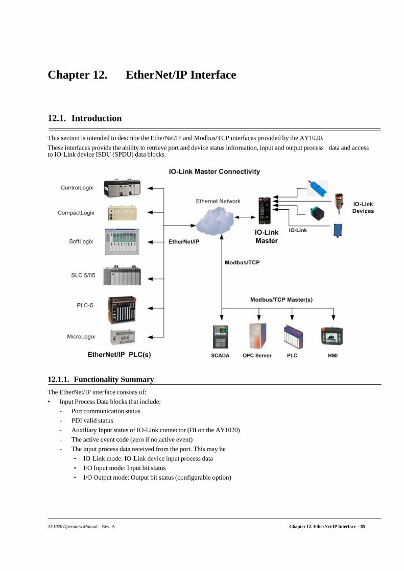
AY1020 Operators Manual: Rev. A Chapter 12. EtherNet/IP Interface - 85
Chapter 12. EtherNet/IP Interface
12.1. Introduction
This section is intended to describe the EtherNet/IP and Modbus/TCP interfaces provided by the AY1020.
These interfaces provide the ability to retrieve port and device status information, input and output process data and access to IO-Link device ISDU (SPDU) data blocks.
12.1.1. Functionality Summary
The EtherNet/IP interface consists of:
• Input Process Data blocks that include:
- Port communication status
- PDI valid status
- Auxiliary Input status of IO-Link connector (DI on the AY1020)
- The active event code (zero if no active event)
- The input process data received from the port. This may be
• IO-Link mode: IO-Link device input process data
• I/O Input mode: Input bit status
• I/O Output mode: Output bit status (configurable option)
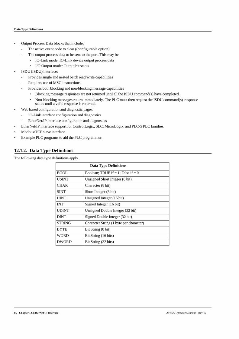
86 - Chapter 12. EtherNet/IP Interface AY1020 Operators Manual: Rev. A
Data Type Definitions
• Output Process Data blocks that include:
- The active event code to clear ((configurable option)
- The output process data to be sent to the port. This may be
• IO-Link mode: IO-Link device output process data
• I/O Output mode: Output bit status
• ISDU (ISDU) interface:
- Provides single and nested batch read/write capabilities
- Requires use of MSG instructions
- Provides both blocking and non-blocking message capabilities
• Blocking message responses are not returned until all the ISDU command(s) have completed.
• Non-blocking messages return immediately. The PLC must then request the ISDU command(s) response status until a valid response is returned.
• Web based configuration and diagnostic pages:
- IO-Link interface configuration and diagnostics
- EtherNet/IP interface configuration and diagnostics
• EtherNet/IP interface support for ControlLogix, SLC, MicroLogix, and PLC-5 PLC families.
• Modbus/TCP slave interface.
• Example PLC programs to aid the PLC programmer.
12.1.2. Data Type Definitions
The following data type definitions apply.
Data Type Definitions
BOOL Boolean; TRUE if = 1; False if = 0
USINT Unsigned Short Integer (8 bit)
CHAR Character (8 bit)
SINT Short Integer (8 bit)
UINT Unsigned Integer (16 bit)
INT Signed Integer (16 bit)
UDINT Unsigned Double Integer (32 bit)
DINT Signed Double Integer (32 bit)
STRING Character String (1 byte per character)
BYTE Bit String (8 bit)
WORD Bit String (16 bits)
DWORD Bit String (32 bits)
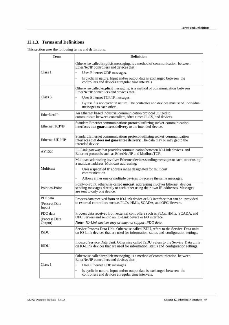
AY1020 Operators Manual: Rev. A Chapter 12. EtherNet/IP Interface - 87
Terms and Definitions
12.1.3. Terms and Definitions
This section uses the following terms and definitions.
Term Definition
Class 1
Otherwise called implicit messaging, is a method of communication between EtherNet/IP controllers and devices that:
• Uses Ethernet UDP messages.
• Is cyclic in nature. Input and/or output data is exchanged between the controllers and devices at regular time intervals.
Class 3
Otherwise called explicit messaging, is a method of communication between EtherNet/IP controllers and devices that:
• Uses Ethernet TCP/IP messages.
• By itself is not cyclic in nature. The controller and devices must send individual messages to each other.
EtherNet/IP An Ethernet based industrial communication protocol utilized to communicate between controllers, often times PLCS, and devices.
Ethernet TCP/IP Standard Ethernet communications protocol utilizing socket communication interfaces that guarantees delivery to the intended device.
Ethernet UDP/IP Standard Ethernet communications protocol utilizing socket communication interfaces that does not guarantee delivery. The data may or may get to the intended device.
AY1020 IO-Link gateway that provides communication between IO-Link devices and Ethernet protocols such as EtherNet/IP and Modbus/TCP.
Multicast
Multicast addressing involves Ethernet devices sending messages to each other using a multicast address. Multicast addressing:
• Uses a specified IP address range designated for multicast communication.
• Allows either one or multiple devices to receive the same messages.
Point-to-Point Point-to-Point, otherwise called unicast, addressing involves Ethernet devices sending messages directly to each other using their own IP addresses. Messages are sent to only one device.
PDI data
(Process Data Input)
Process data received from an IO-Link device or I/O interface that can be provided to external controllers such as PLCs, HMIs, SCADA, and OPC Servers.
PDO data
(Process Data Output)
Process data received from external controllers such as PLCs, HMIs, SCADA, and OPC Servers and sent to an IO-Link device or I/O interface.
Note: IO-Link devices may or may not support PDO data.
ISDU Service Process Data Unit. Otherwise called ISDU, refers to the Service Data units on IO-Link devices that are used for information, status and configuration settings.
ISDU Indexed Service Data Unit. Otherwise called ISDU, refers to the Service Data units on IO-Link devices that are used for information, status and configuration settings.
Class 1
Otherwise called implicit messaging, is a method of communication between EtherNet/IP controllers and devices that:
• Uses Ethernet UDP messages.
• Is cyclic in nature. Input and/or output data is exchanged between the controllers and devices at regular time intervals.
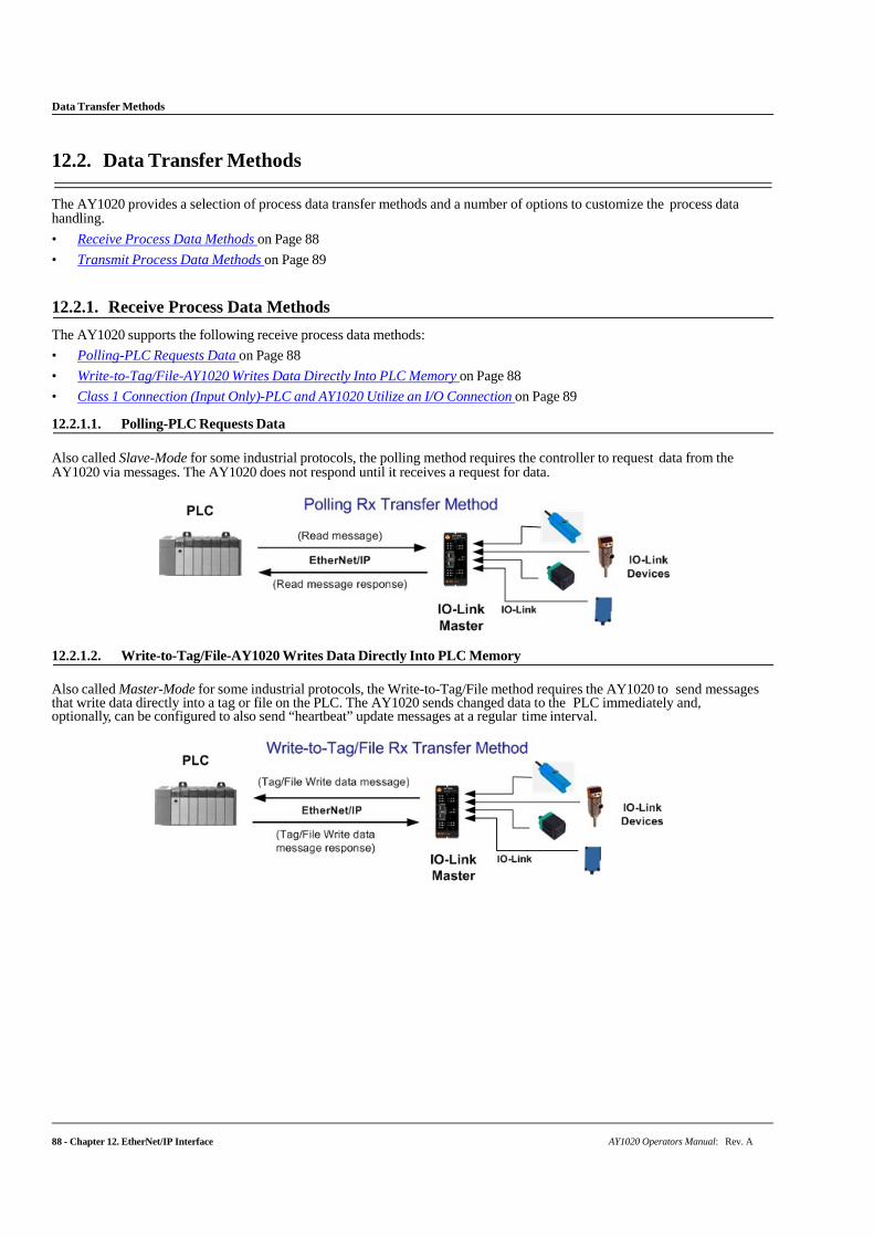
88 - Chapter 12. EtherNet/IP Interface AY1020 Operators Manual: Rev. A
Data Transfer Methods
12.2. Data Transfer Methods
The AY1020 provides a selection of process data transfer methods and a number of options to customize the process data handling.
• Receive Process Data Methods on Page 88
• Transmit Process Data Methods on Page 89
12.2.1. Receive Process Data Methods
The AY1020 supports the following receive process data methods:
• Polling-PLC Requests Data on Page 88
• Write-to-Tag/File-AY1020 Writes Data Directly Into PLC Memory on Page 88
• Class 1 Connection (Input Only)-PLC and AY1020 Utilize an I/O Connection on Page 89
12.2.1.1. Polling-PLC Requests Data
Also called Slave-Mode for some industrial protocols, the polling method requires the controller to request data from the AY1020 via messages. The AY1020 does not respond until it receives a request for data.
12.2.1.2. Write-to-Tag/File-AY1020 Writes Data Directly Into PLC Memory
Also called Master-Mode for some industrial protocols, the Write-to-Tag/File method requires the AY1020 to send messages that write data directly into a tag or file on the PLC. The AY1020 sends changed data to the PLC immediately and, optionally, can be configured to also send “heartbeat” update messages at a regular time interval.

AY1020 Operators Manual: Rev. A Chapter 12. EtherNet/IP Interface - 89
Class 1 Connection (Input Only)-PLC and AY1020 Utilize an I/O Connection
12.2.1.3. Class 1 Connection (Input Only)-PLC and AY1020 Utilize an I/O Connection
Also called I/O Mode for some industrial protocols, the Class 1 connection method requires the AY1020 and PLC to connect to each via an I/O connection. For EtherNet/IP, a connection over UDP must first be created. Once the connection is established, the AY1020 continually sends input data to the PLC at a PLC configurable rate.
12.2.2. Transmit Process Data Methods
The AY1020 supports the following transmit process data methods:
• PLC-Writes on Page 89
• Read-from-Tag/File-AY1020 Reads Data from PLC Memory on Page 89
• Class 1 Connection (Input and Output)-PLC and AY1020 Utilize an I/O Connection on Page 90
12.2.2.1. PLC-Writes
Also called Slave-Mode for some industrial protocols, the PLC-Writes method requires the PLC to send data to the AY1020 via write messages.
12.2.2.2. Read-from-Tag/File-AY1020 Reads Data from PLC Memory
Also called Master-Mode for some industrial protocols, the Read-from-Tag/File method requires the AY1020 to read data from a tag or file on the PLC. In this method, the AY1020 requests data from the PLC at configurable time intervals.
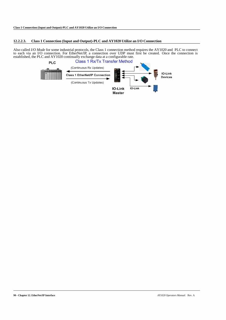
Class 1 Connection (Input and Output)-PLC and AY1020 Utilize an I/O Connection
90 - Chapter 12. EtherNet/IP Interface AY1020 Operators Manual: Rev. A
12.2.2.3. Class 1 Connection (Input and Output)-PLC and AY1020 Utilize an I/O Connection
Also called I/O Mode for some industrial protocols, the Class 1 connection method requires the AY1020 and PLC to connect to each via an I/O connection. For EtherNet/IP, a connection over UDP must first be created. Once the connection is established, the PLC and AY1020 continually exchange data at a configurable rate.
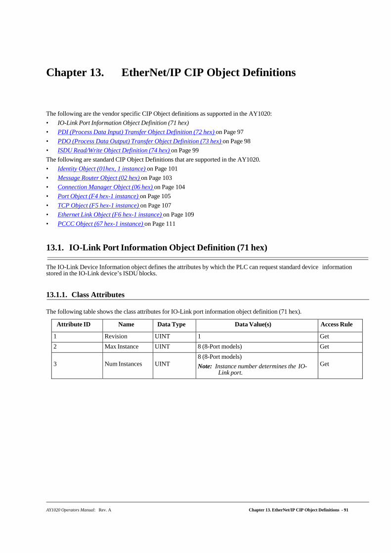
AY1020 Operators Manual: Rev. A Chapter 13. EtherNet/IP CIP Object Definitions - 91
Chapter 13. EtherNet/IP CIP Object Definitions
The following are the vendor specific CIP Object definitions as supported in the AY1020:
• IO-Link Port Information Object Definition (71 hex)
• PDI (Process Data Input) Transfer Object Definition (72 hex) on Page 97
• PDO (Process Data Output) Transfer Object Definition (73 hex) on Page 98
• ISDU Read/Write Object Definition (74 hex) on Page 99
The following are standard CIP Object Definitions that are supported in the AY1020.
• Identity Object (01hex, 1 instance) on Page 101
• Message Router Object (02 hex) on Page 103
• Connection Manager Object (06 hex) on Page 104
• Port Object (F4 hex-1 instance) on Page 105
• TCP Object (F5 hex-1 instance) on Page 107
• Ethernet Link Object (F6 hex-1 instance) on Page 109
• PCCC Object (67 hex-1 instance) on Page 111
13.1. IO-Link Port Information Object Definition (71 hex)
The IO-Link Device Information object defines the attributes by which the PLC can request standard device information stored in the IO-Link device’s ISDU blocks.
13.1.1. Class Attributes
The following table shows the class attributes for IO-Link port information object definition (71 hex).
Attribute ID Name Data Type Data Value(s) Access Rule
1 Revision UINT 1 Get
2 Max Instance UINT 8 (8-Port models) Get
3
Num Instances
UINT
8 (8-Port models)
Note: Instance number determines the IO-Link port.
Get
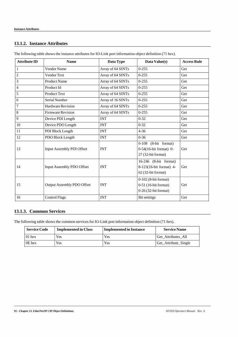
Instance Attributes
92 - Chapter 13. EtherNet/IP CIP Object Definitions AY1020 Operators Manual: Rev. A
13.1.2. Instance Attributes
The following table shows the instance attributes for IO-Link port information object definition (71 hex).
Attribute ID Name Data Type Data Value(s) Access Rule
1 Vendor Name Array of 64 SINTs 0-255 Get
2 Vendor Text Array of 64 SINTs 0-255 Get
3 Product Name Array of 64 SINTs 0-255 Get
4 Product Id Array of 64 SINTs 0-255 Get
5 Product Text Array of 64 SINTs 0-255 Get
6 Serial Number Array of 16 SINTs 0-255 Get
7 Hardware Revision Array of 64 SINTs 0-255 Get
8 Firmware Revision Array of 64 SINTs 0-255 Get
9 Device PDI Length INT 0-32 Get
10 Device PDO Length INT 0-32 Get
11 PDI Block Length INT 4-36 Get
12 PDO Block Length INT 0-36 Get
13
Input Assembly PDI Offset
INT
0-108 (8-bit format)
0-54(16-bit format) 0-
27 (32-bit format)
Get
14
Input Assembly PDO Offset
INT
16-246 (8-bit format)
8-123(16-bit format) 4-
62 (32-bit format)
Get
15
Output Assembly PDO Offset
INT
0-102 (8-bit format)
0-51 (16-bit format)
0-26 (32-bit format)
Get
16 Control Flags INT Bit settings Get
13.1.3. Common Services
The following table shows the common services for IO-Link port information object definition (71 hex).
Service Code Implemented in Class Implemented in Instance Service Name
01 hex Yes Yes Get_Attributes_All
0E hex Yes Yes Get_Attribute_Single
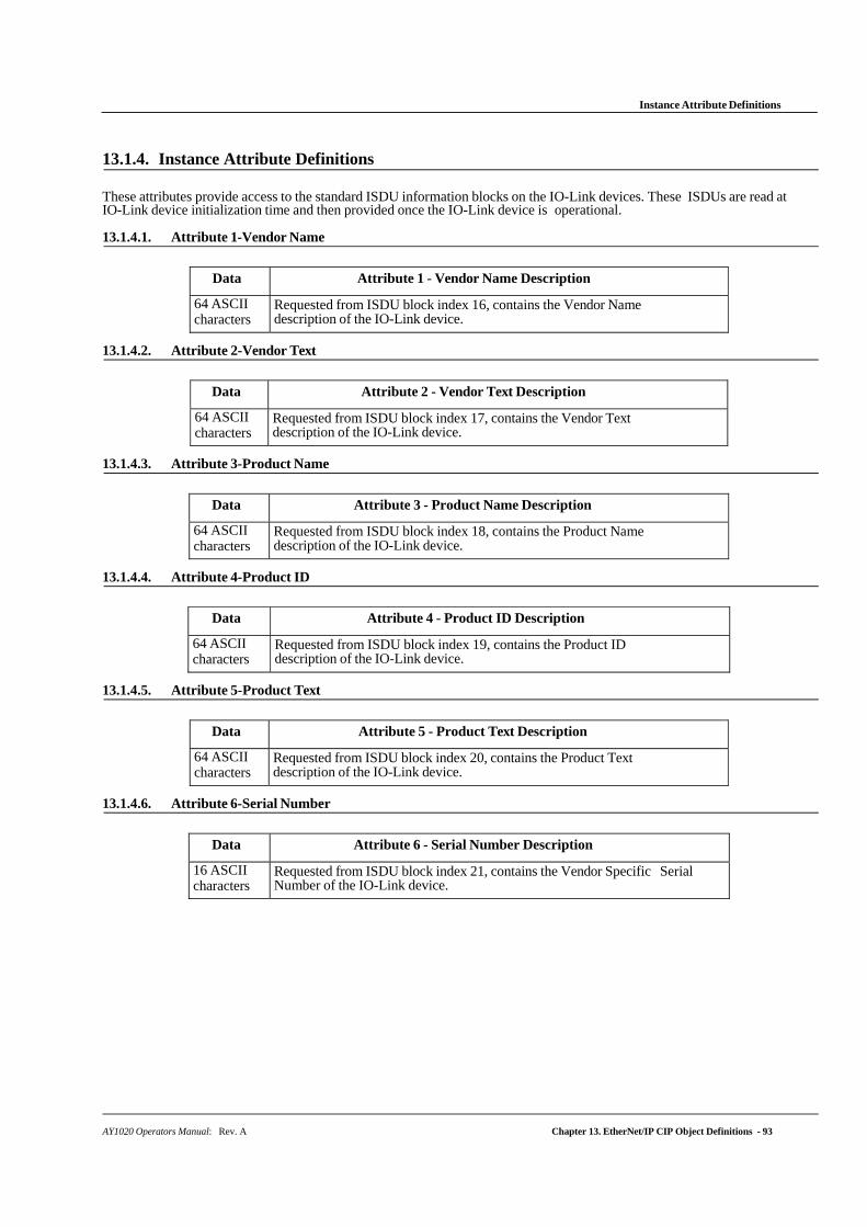
Instance Attribute Definitions
AY1020 Operators Manual: Rev. A Chapter 13. EtherNet/IP CIP Object Definitions - 93
13.1.4. Instance Attribute Definitions
These attributes provide access to the standard ISDU information blocks on the IO-Link devices. These ISDUs are read at IO-Link device initialization time and then provided once the IO-Link device is operational.
13.1.4.1. Attribute 1-Vendor Name
Data Attribute 1 - Vendor Name Description
64 ASCII characters
Requested from ISDU block index 16, contains the Vendor Name description of the IO-Link device.
13.1.4.2. Attribute 2-Vendor Text
Data Attribute 2 - Vendor Text Description
64 ASCII characters
Requested from ISDU block index 17, contains the Vendor Text description of the IO-Link device.
13.1.4.3. Attribute 3-Product Name
Data Attribute 3 - Product Name Description
64 ASCII characters
Requested from ISDU block index 18, contains the Product Name description of the IO-Link device.
13.1.4.4. Attribute 4-Product ID
Data Attribute 4 - Product ID Description
64 ASCII characters
Requested from ISDU block index 19, contains the Product ID description of the IO-Link device.
13.1.4.5. Attribute 5-Product Text
Data Attribute 5 - Product Text Description
64 ASCII characters
Requested from ISDU block index 20, contains the Product Text description of the IO-Link device.
13.1.4.6. Attribute 6-Serial Number
Data Attribute 6 - Serial Number Description
16 ASCII characters
Requested from ISDU block index 21, contains the Vendor Specific Serial Number of the IO-Link device.
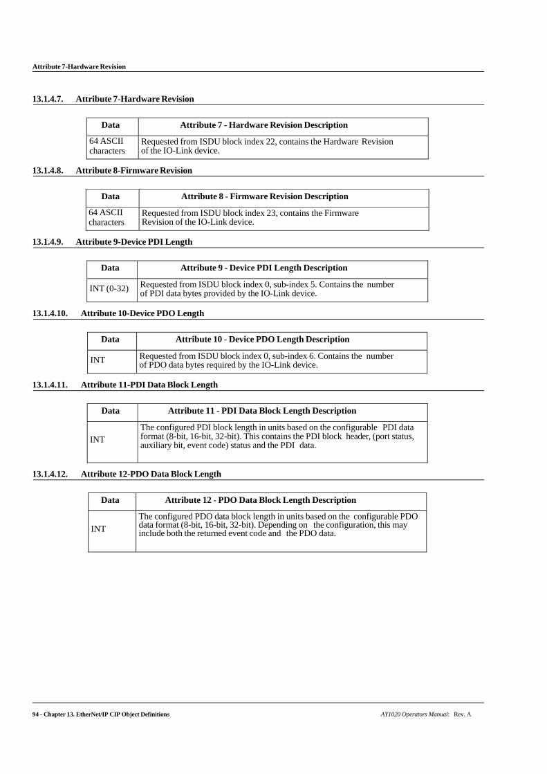
94 - Chapter 13. EtherNet/IP CIP Object Definitions AY1020 Operators Manual: Rev. A
Attribute 7-Hardware Revision
13.1.4.7. Attribute 7-Hardware Revision
Data Attribute 7 - Hardware Revision Description
64 ASCII characters
Requested from ISDU block index 22, contains the Hardware Revision of the IO-Link device.
13.1.4.8. Attribute 8-Firmware Revision
Data Attribute 8 - Firmware Revision Description
64 ASCII characters
Requested from ISDU block index 23, contains the Firmware Revision of the IO-Link device.
13.1.4.9. Attribute 9-Device PDI Length
Data Attribute 9 - Device PDI Length Description
INT (0-32) Requested from ISDU block index 0, sub-index 5. Contains the number of PDI data bytes provided by the IO-Link device.
13.1.4.10. Attribute 10-Device PDO Length
Data Attribute 10 - Device PDO Length Description
INT Requested from ISDU block index 0, sub-index 6. Contains the number of PDO data bytes required by the IO-Link device.
13.1.4.11. Attribute 11-PDI Data Block Length
Data Attribute 11 - PDI Data Block Length Description
INT
The configured PDI block length in units based on the configurable PDI data format (8-bit, 16-bit, 32-bit). This contains the PDI block header, (port status, auxiliary bit, event code) status and the PDI data.
13.1.4.12. Attribute 12-PDO Data Block Length
Data Attribute 12 - PDO Data Block Length Description
INT
The configured PDO data block length in units based on the configurable PDO data format (8-bit, 16-bit, 32-bit). Depending on the configuration, this may include both the returned event code and the PDO data.
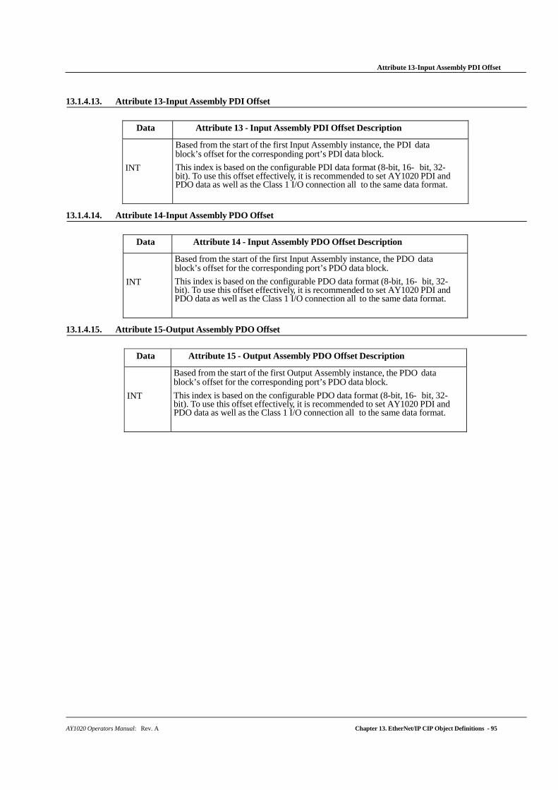
AY1020 Operators Manual: Rev. A Chapter 13. EtherNet/IP CIP Object Definitions - 95
Attribute 13-Input Assembly PDI Offset
13.1.4.13. Attribute 13-Input Assembly PDI Offset
Data Attribute 13 - Input Assembly PDI Offset Description
INT
Based from the start of the first Input Assembly instance, the PDI data block’s offset for the corresponding port’s PDI data block.
This index is based on the configurable PDI data format (8-bit, 16- bit, 32-bit). To use this offset effectively, it is recommended to set AY1020 PDI and PDO data as well as the Class 1 I/O connection all to the same data format.
13.1.4.14. Attribute 14-Input Assembly PDO Offset
Data Attribute 14 - Input Assembly PDO Offset Description
INT
Based from the start of the first Input Assembly instance, the PDO data block’s offset for the corresponding port’s PDO data block.
This index is based on the configurable PDO data format (8-bit, 16- bit, 32-bit). To use this offset effectively, it is recommended to set AY1020 PDI and PDO data as well as the Class 1 I/O connection all to the same data format.
13.1.4.15. Attribute 15-Output Assembly PDO Offset
Data Attribute 15 - Output Assembly PDO Offset Description
INT
Based from the start of the first Output Assembly instance, the PDO data block’s offset for the corresponding port’s PDO data block.
This index is based on the configurable PDO data format (8-bit, 16- bit, 32-bit). To use this offset effectively, it is recommended to set AY1020 PDI and PDO data as well as the Class 1 I/O connection all to the same data format.

96 - Chapter 13. EtherNet/IP CIP Object Definitions AY1020 Operators Manual: Rev. A
Attribute 16-Control Flags
13.1.4.16. Attribute 16-Control Flags
Data Attribute 16 - Control Flags Description
INT
(bit- mapped word)
Bit 0 (01h):
1 = Indicates that the event code to clear is expected in the PDO block 0 = Indicates that the event code to clear is not expected in the PDO block.
Bit 1 (02h):
1 = Indicates that the IO-Link device is SIO mode capable 0 = Indicates that the IO-Link device is not SIO mode capable
Bits 2 (04h)
1 = Indicates that Class 1 Rx (receive PDI block) is enabled 0 = Indicates that Class 1 Rx (receive PDI block) is disabled
Bit 3 (08h):
1 = Indicates that Class 1 Tx (transmit PDO) is enabled 0 = Indicates that Class 1 Tx (transmit PDO) is disabled
Bit 4 (10h):
1 = Indicates that the digital output settings for DI and C/Q are expected in the PDO block
0 = Indicates that the digital output settings for DI and C/Q are not expected in the PDO block.
Bit 5 -15: Reserved

AY1020 Operators Manual: Rev. A Chapter 13. EtherNet/IP CIP Object Definitions - 97
PDI (Process Data Input) Transfer Object Definition (72 hex)
13.2. PDI (Process Data Input) Transfer Object Definition (72 hex)
The PDI Transfer object defines the attributes by which the PLC can request the PDI data block from the AY1020.
13.2.1. Class Attributes
The following table displays Class Attributes for the PDI Transfer Object Definition (72 hex).
Attribute ID Name Data Type Data Value(s) Access Rule
1 Revision UINT 1 Get
2 Max Instance UINT 1 Get
3 Num Instances UINT 1 Get
13.2.2. Instance Attributes
The following table displays Instance Attributes for the PDI Transfer Object Definition (72 hex).
Attribute ID Name Data Type Length Data Values Access Rule
1 Port 1 PDI data block Array of BYTEs 4-36 bytes 0-255 Get
2 Port 2 PDI data block Array of BYTEs 4-36 bytes 0-255 Get
3 Port 3 PDI data block Array of BYTEs 4-36 bytes 0-255 Get
4 Port 4 PDI data block Array of BYTEs 4-36 bytes 0-255 Get
8-Port Models Only:
5 Port 5 PDI data block Array of BYTEs 4-36 bytes 0-255 Get
6 Port 6 PDI data block Array of BYTEs 4-36 bytes 0-255 Get
7 Port 7 PDI data block Array of BYTEs 4-36 bytes 0-255 Get
8 Port 8 PDI data block Array of BYTEs 4-36 bytes 0-255 Get
13.2.3. Common Services
The following table shows Common Services for the PDI Transfer Object Definition (72 hex).
Service Code Implemented in Class Implemented in Instance Service Name 01 hex Yes Yes Get_Attributes_All 0E hex Yes Yes Get_Attribute_Single
13.2.4. Instance Attribute Definitions - Attribute 1 to 4-PDI Data Blocks
These attributes provide access to the PDI data blocks.
• Get Attribute Single requests return the PDI data block for a specific port.
• Get Attribute All requests return all PDI data blocks from the AY1020.
All PDI data is returned in the configured PDI format (8-bit, 16-bit or 32-bit). Refer to 13.2. PDI (Process Data Input) Transfer Object Definition (72 hex) on Page 97 for a detailed explanation of the PDI data block.
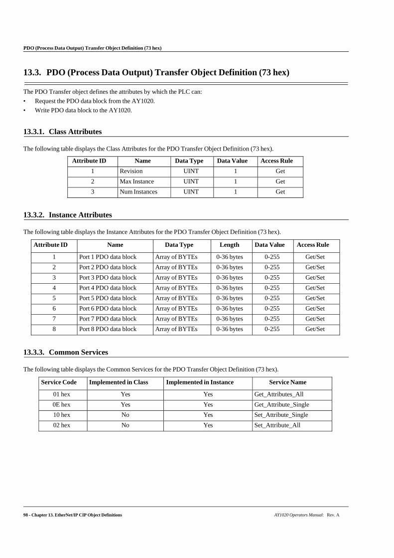
98 - Chapter 13. EtherNet/IP CIP Object Definitions AY1020 Operators Manual: Rev. A
PDO (Process Data Output) Transfer Object Definition (73 hex)
13.3. PDO (Process Data Output) Transfer Object Definition (73 hex)
The PDO Transfer object defines the attributes by which the PLC can:
• Request the PDO data block from the AY1020.
• Write PDO data block to the AY1020.
13.3.1. Class Attributes
The following table displays the Class Attributes for the PDO Transfer Object Definition (73 hex).
Attribute ID Name Data Type Data Value Access Rule
1 Revision UINT 1 Get
2 Max Instance UINT 1 Get
3 Num Instances UINT 1 Get
13.3.2. Instance Attributes
The following table displays the Instance Attributes for the PDO Transfer Object Definition (73 hex).
Attribute ID Name Data Type Length Data Value Access Rule
1 Port 1 PDO data block Array of BYTEs 0-36 bytes 0-255 Get/Set
2 Port 2 PDO data block Array of BYTEs 0-36 bytes 0-255 Get/Set
3 Port 3 PDO data block Array of BYTEs 0-36 bytes 0-255 Get/Set
4 Port 4 PDO data block Array of BYTEs 0-36 bytes 0-255 Get/Set
5 Port 5 PDO data block Array of BYTEs 0-36 bytes 0-255 Get/Set
6 Port 6 PDO data block Array of BYTEs 0-36 bytes 0-255 Get/Set
7 Port 7 PDO data block Array of BYTEs 0-36 bytes 0-255 Get/Set
8 Port 8 PDO data block Array of BYTEs 0-36 bytes 0-255 Get/Set
13.3.3. Common Services
The following table displays the Common Services for the PDO Transfer Object Definition (73 hex).
Service Code Implemented in Class Implemented in Instance Service Name
01 hex Yes Yes Get_Attributes_All
0E hex Yes Yes Get_Attribute_Single
10 hex No Yes Set_Attribute_Single
02 hex No Yes Set_Attribute_All
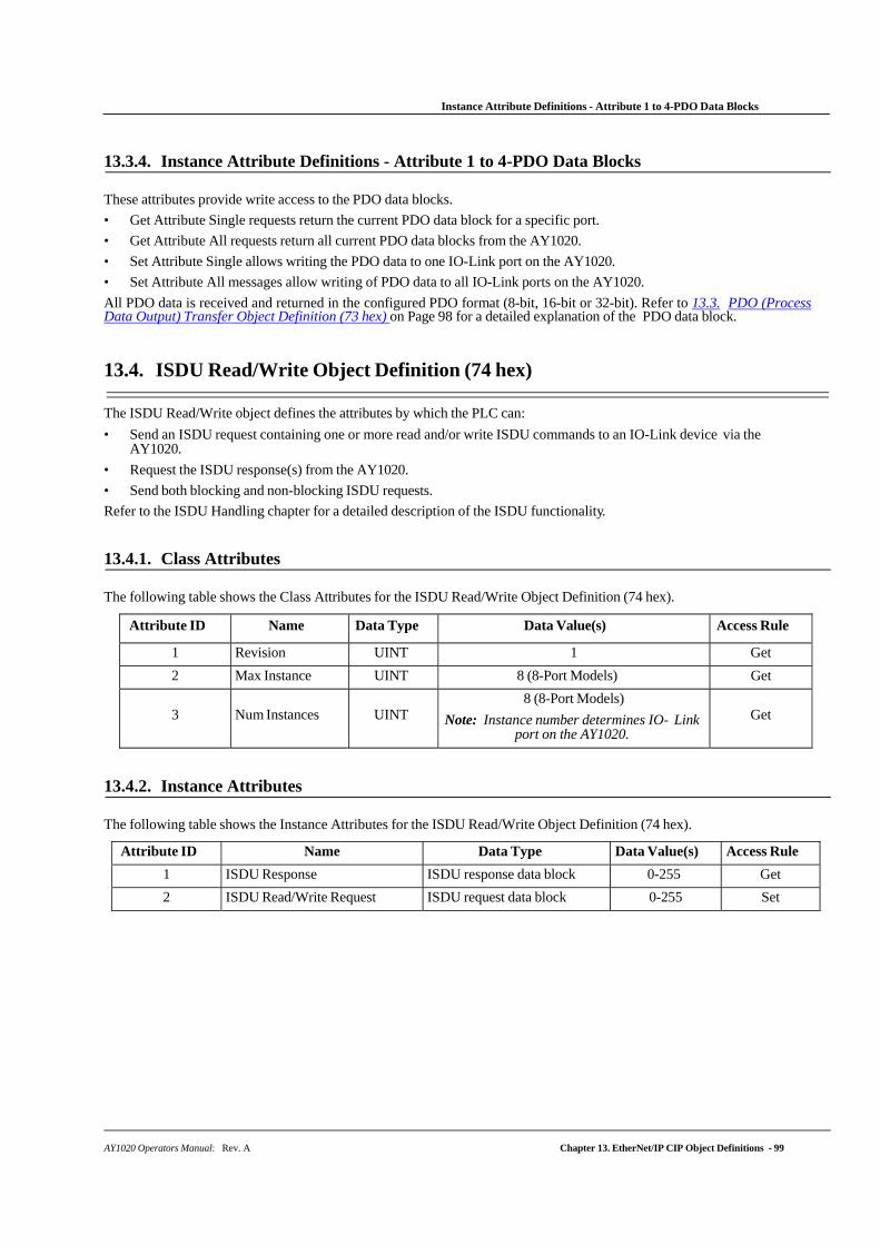
AY1020 Operators Manual: Rev. A Chapter 13. EtherNet/IP CIP Object Definitions - 99
Instance Attribute Definitions - Attribute 1 to 4-PDO Data Blocks
13.3.4. Instance Attribute Definitions - Attribute 1 to 4-PDO Data Blocks
These attributes provide write access to the PDO data blocks.
• Get Attribute Single requests return the current PDO data block for a specific port.
• Get Attribute All requests return all current PDO data blocks from the AY1020.
• Set Attribute Single allows writing the PDO data to one IO-Link port on the AY1020.
• Set Attribute All messages allow writing of PDO data to all IO-Link ports on the AY1020.
All PDO data is received and returned in the configured PDO format (8-bit, 16-bit or 32-bit). Refer to 13.3. PDO (Process Data Output) Transfer Object Definition (73 hex) on Page 98 for a detailed explanation of the PDO data block.
13.4. ISDU Read/Write Object Definition (74 hex)
The ISDU Read/Write object defines the attributes by which the PLC can:
• Send an ISDU request containing one or more read and/or write ISDU commands to an IO-Link device via the AY1020.
• Request the ISDU response(s) from the AY1020.
• Send both blocking and non-blocking ISDU requests.
Refer to the ISDU Handling chapter for a detailed description of the ISDU functionality.
13.4.1. Class Attributes
The following table shows the Class Attributes for the ISDU Read/Write Object Definition (74 hex).
Attribute ID Name Data Type Data Value(s) Access Rule
1 Revision UINT 1 Get
2 Max Instance UINT 8 (8-Port Models) Get
3
Num Instances
UINT
8 (8-Port Models)
Note: Instance number determines IO- Link port on the AY1020.
Get
13.4.2. Instance Attributes
The following table shows the Instance Attributes for the ISDU Read/Write Object Definition (74 hex).
Attribute ID Name Data Type Data Value(s) Access Rule
1 ISDU Response ISDU response data block 0-255 Get
2 ISDU Read/Write Request ISDU request data block 0-255 Set
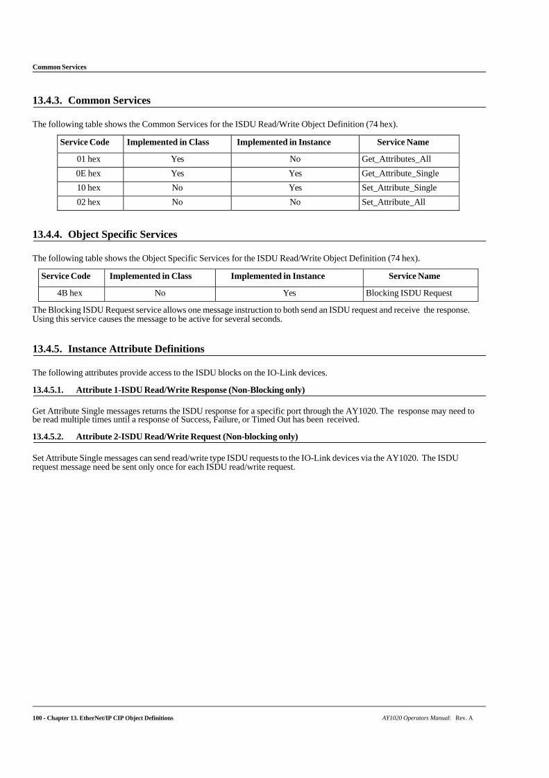
Common Services
100 - Chapter 13. EtherNet/IP CIP Object Definitions AY1020 Operators Manual: Rev. A
13.4.3. Common Services
The following table shows the Common Services for the ISDU Read/Write Object Definition (74 hex).
Service Code Implemented in Class Implemented in Instance Service Name
01 hex Yes No Get_Attributes_All
0E hex Yes Yes Get_Attribute_Single
10 hex No Yes Set_Attribute_Single
02 hex No No Set_Attribute_All
13.4.4. Object Specific Services
The following table shows the Object Specific Services for the ISDU Read/Write Object Definition (74 hex).
Service Code Implemented in Class Implemented in Instance Service Name
4B hex No Yes Blocking ISDU Request
The Blocking ISDU Request service allows one message instruction to both send an ISDU request and receive the response. Using this service causes the message to be active for several seconds.
13.4.5. Instance Attribute Definitions
The following attributes provide access to the ISDU blocks on the IO-Link devices.
13.4.5.1. Attribute 1-ISDU Read/Write Response (Non-Blocking only)
Get Attribute Single messages returns the ISDU response for a specific port through the AY1020. The response may need to be read multiple times until a response of Success, Failure, or Timed Out has been received.
13.4.5.2. Attribute 2-ISDU Read/Write Request (Non-blocking only)
Set Attribute Single messages can send read/write type ISDU requests to the IO-Link devices via the AY1020. The ISDU request message need be sent only once for each ISDU read/write request.
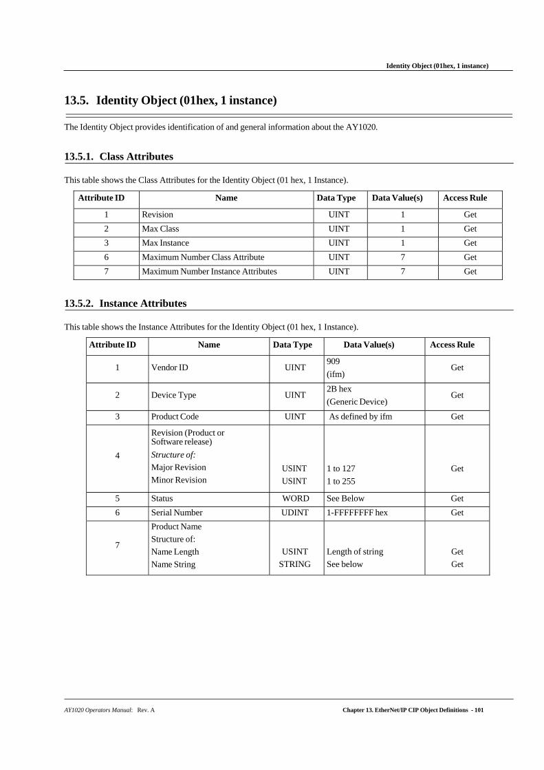
Identity Object (01hex, 1 instance)
AY1020 Operators Manual: Rev. A Chapter 13. EtherNet/IP CIP Object Definitions - 101
13.5. Identity Object (01hex, 1 instance)
The Identity Object provides identification of and general information about the AY1020.
13.5.1. Class Attributes
This table shows the Class Attributes for the Identity Object (01 hex, 1 Instance).
Attribute ID Name Data Type Data Value(s) Access Rule
1 Revision UINT 1 Get
2 Max Class UINT 1 Get
3 Max Instance UINT 1 Get
6 Maximum Number Class Attribute UINT 7 Get
7 Maximum Number Instance Attributes UINT 7 Get
13.5.2. Instance Attributes
This table shows the Instance Attributes for the Identity Object (01 hex, 1 Instance).
Attribute ID Name Data Type Data Value(s) Access Rule
1 Vendor ID UINT 909
(ifm) Get
2 Device Type UINT 2B hex
(Generic Device) Get
3 Product Code UINT As defined by ifm Get
4
Revision (Product or Software release)
Structure of:
Major Revision
Minor Revision
USINT
USINT
1 to 127
1 to 255
Get
5 Status WORD See Below Get
6 Serial Number UDINT 1-FFFFFFFF hex Get
7
Product Name
Structure of:
Name Length
Name String
USINT
STRING
Length of string
See below
Get
Get
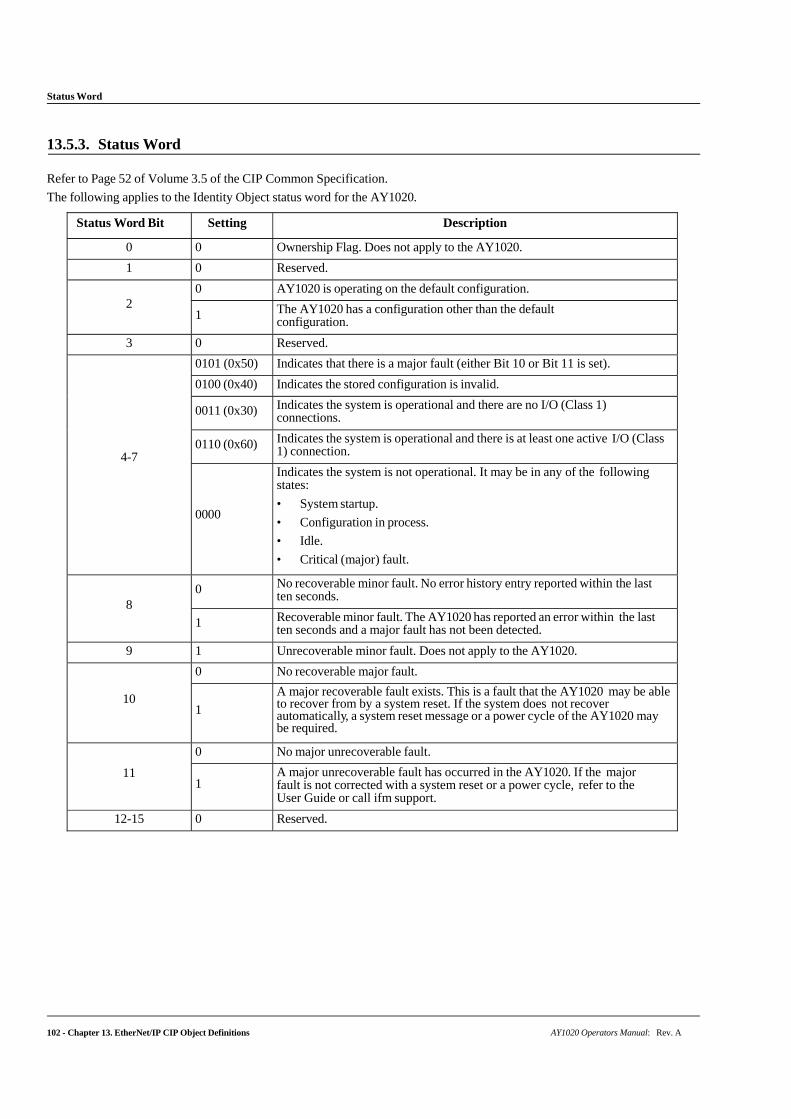
Status Word
102 - Chapter 13. EtherNet/IP CIP Object Definitions AY1020 Operators Manual: Rev. A
13.5.3. Status Word
Refer to Page 52 of Volume 3.5 of the CIP Common Specification.
The following applies to the Identity Object status word for the AY1020.
Status Word Bit Setting Description
0 0 Ownership Flag. Does not apply to the AY1020.
1 0 Reserved.
2
0 AY1020 is operating on the default configuration.
1 The AY1020 has a configuration other than the default configuration.
3 0 Reserved.
4-7
0101 (0x50) Indicates that there is a major fault (either Bit 10 or Bit 11 is set).
0100 (0x40) Indicates the stored configuration is invalid.
0011 (0x30) Indicates the system is operational and there are no I/O (Class 1) connections.
0110 (0x60) Indicates the system is operational and there is at least one active I/O (Class 1) connection.
0000
Indicates the system is not operational. It may be in any of the following states:
• System startup.
• Configuration in process.
• Idle.
• Critical (major) fault.
8
0 No recoverable minor fault. No error history entry reported within the last ten seconds.
1 Recoverable minor fault. The AY1020 has reported an error within the last ten seconds and a major fault has not been detected.
9 1 Unrecoverable minor fault. Does not apply to the AY1020.
10
0 No recoverable major fault.
1
A major recoverable fault exists. This is a fault that the AY1020 may be able to recover from by a system reset. If the system does not recover automatically, a system reset message or a power cycle of the AY1020 may be required.
11
0 No major unrecoverable fault.
1 A major unrecoverable fault has occurred in the AY1020. If the major fault is not corrected with a system reset or a power cycle, refer to the User Guide or call ifm support.
12-15 0 Reserved.
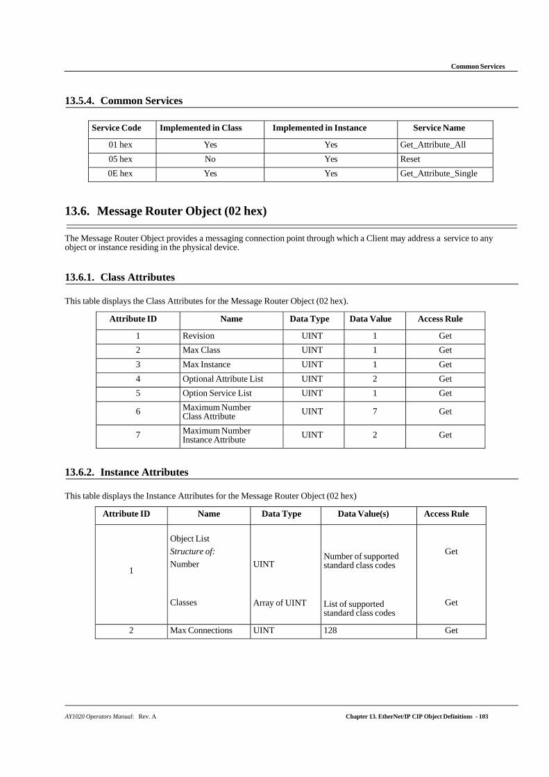
Common Services
AY1020 Operators Manual: Rev. A Chapter 13. EtherNet/IP CIP Object Definitions - 103
13.5.4. Common Services
Service Code Implemented in Class Implemented in Instance Service Name
01 hex Yes Yes Get_Attribute_All
05 hex No Yes Reset
0E hex Yes Yes Get_Attribute_Single
13.6. Message Router Object (02 hex)
The Message Router Object provides a messaging connection point through which a Client may address a service to any object or instance residing in the physical device.
13.6.1. Class Attributes
This table displays the Class Attributes for the Message Router Object (02 hex).
Attribute ID Name Data Type Data Value Access Rule
1 Revision UINT 1 Get
2 Max Class UINT 1 Get
3 Max Instance UINT 1 Get
4 Optional Attribute List UINT 2 Get
5 Option Service List UINT 1 Get
6 Maximum Number Class Attribute UINT 7 Get
7 Maximum Number Instance Attribute UINT 2 Get
13.6.2. Instance Attributes
This table displays the Instance Attributes for the Message Router Object (02 hex)
Attribute ID Name Data Type Data Value(s) Access Rule
1
Object List
Structure of:
Number
Classes
UINT
Array of UINT
Number of supported standard class codes
List of supported standard class codes
Get
Get
2 Max Connections UINT 128 Get
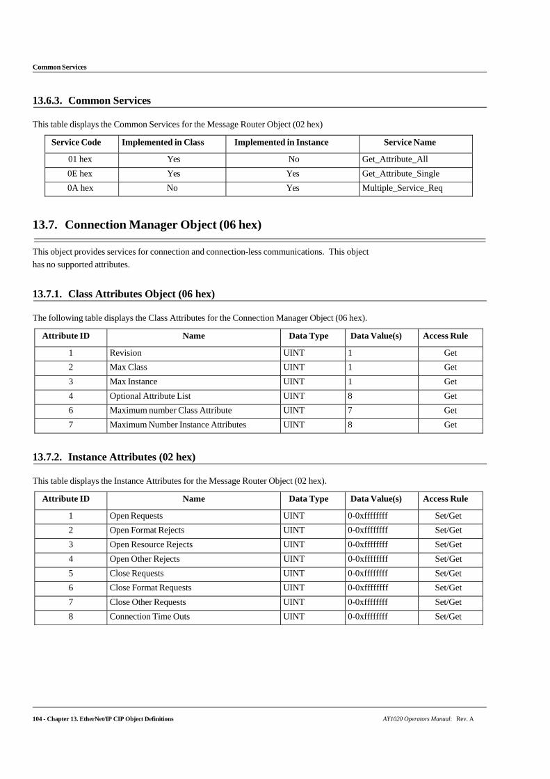
104 - Chapter 13. EtherNet/IP CIP Object Definitions AY1020 Operators Manual: Rev. A
Common Services
13.6.3. Common Services
This table displays the Common Services for the Message Router Object (02 hex)
Service Code Implemented in Class Implemented in Instance Service Name
01 hex Yes No Get_Attribute_All
0E hex Yes Yes Get_Attribute_Single
0A hex No Yes Multiple_Service_Req
13.7. Connection Manager Object (06 hex)
This object provides services for connection and connection-less communications. This object
has no supported attributes.
13.7.1. Class Attributes Object (06 hex)
The following table displays the Class Attributes for the Connection Manager Object (06 hex).
Attribute ID Name Data Type Data Value(s) Access Rule
1 Revision UINT 1 Get
2 Max Class UINT 1 Get
3 Max Instance UINT 1 Get
4 Optional Attribute List UINT 8 Get
6 Maximum number Class Attribute UINT 7 Get
7 Maximum Number Instance Attributes UINT 8 Get
13.7.2. Instance Attributes (02 hex)
This table displays the Instance Attributes for the Message Router Object (02 hex).
Attribute ID Name Data Type Data Value(s) Access Rule
1 Open Requests UINT 0-0xffffffff Set/Get
2 Open Format Rejects UINT 0-0xffffffff Set/Get
3 Open Resource Rejects UINT 0-0xffffffff Set/Get
4 Open Other Rejects UINT 0-0xffffffff Set/Get
5 Close Requests UINT 0-0xffffffff Set/Get
6 Close Format Requests UINT 0-0xffffffff Set/Get
7 Close Other Requests UINT 0-0xffffffff Set/Get
8 Connection Time Outs UINT 0-0xffffffff Set/Get
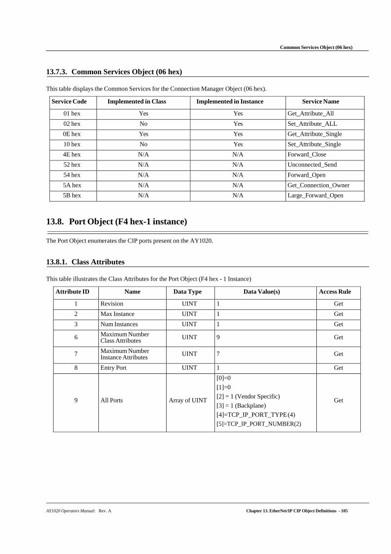
AY1020 Operators Manual: Rev. A Chapter 13. EtherNet/IP CIP Object Definitions - 105
Common Services Object (06 hex)
13.7.3. Common Services Object (06 hex)
This table displays the Common Services for the Connection Manager Object (06 hex).
Service Code Implemented in Class Implemented in Instance Service Name
01 hex Yes Yes Get_Attribute_All
02 hex No Yes Set_Attribute_ALL
0E hex Yes Yes Get_Attribute_Single
10 hex No Yes Set_Attribute_Single
4E hex N/A N/A Forward_Close
52 hex N/A N/A Unconnected_Send
54 hex N/A N/A Forward_Open
5A hex N/A N/A Get_Connection_Owner
5B hex N/A N/A Large_Forward_Open
13.8. Port Object (F4 hex-1 instance)
The Port Object enumerates the CIP ports present on the AY1020.
13.8.1. Class Attributes
This table illustrates the Class Attributes for the Port Object (F4 hex - 1 Instance)
Attribute ID Name Data Type Data Value(s) Access Rule
1 Revision UINT 1 Get
2 Max Instance UINT 1 Get
3 Num Instances UINT 1 Get
6 Maximum Number Class Attributes UINT 9 Get
7 Maximum Number Instance Attributes UINT 7 Get
8 Entry Port UINT 1 Get
9
All Ports
Array of UINT
[0]=0
[1]=0
[2] = 1 (Vendor Specific)
[3] = 1 (Backplane)
[4]=TCP_IP_PORT_TYPE (4)
[5]=TCP_IP_PORT_NUMBER(2)
Get
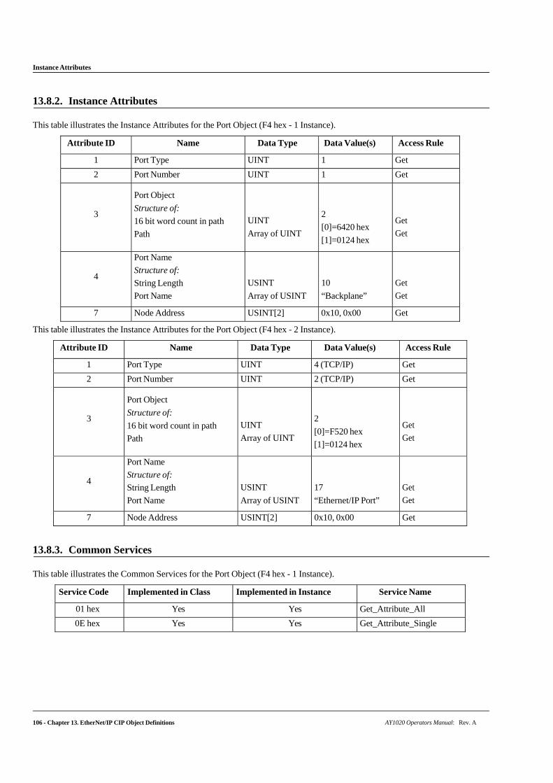
106 - Chapter 13. EtherNet/IP CIP Object Definitions AY1020 Operators Manual: Rev. A
Instance Attributes
13.8.2. Instance Attributes
This table illustrates the Instance Attributes for the Port Object (F4 hex - 1 Instance).
Attribute ID Name Data Type Data Value(s) Access Rule
1 Port Type UINT 1 Get
2 Port Number UINT 1 Get
3
Port Object
Structure of:
16 bit word count in path
Path
UINT
Array of UINT
2
[0]=6420 hex
[1]=0124 hex
Get
Get
4
Port Name
Structure of:
String Length
Port Name
USINT
Array of USINT
10
“Backplane”
Get
Get
7 Node Address USINT[2] 0x10, 0x00 Get
This table illustrates the Instance Attributes for the Port Object (F4 hex - 2 Instance).
Attribute ID Name Data Type Data Value(s) Access Rule
1 Port Type UINT 4 (TCP/IP) Get
2 Port Number UINT 2 (TCP/IP) Get
3
Port Object
Structure of:
16 bit word count in path
Path
UINT
Array of UINT
2
[0]=F520 hex
[1]=0124 hex
Get
Get
4
Port Name
Structure of:
String Length
Port Name
USINT
Array of USINT
17
“Ethernet/IP Port”
Get
Get
7 Node Address USINT[2] 0x10, 0x00 Get
13.8.3. Common Services
This table illustrates the Common Services for the Port Object (F4 hex - 1 Instance).
Service Code Implemented in Class Implemented in Instance Service Name
01 hex Yes Yes Get_Attribute_All
0E hex Yes Yes Get_Attribute_Single
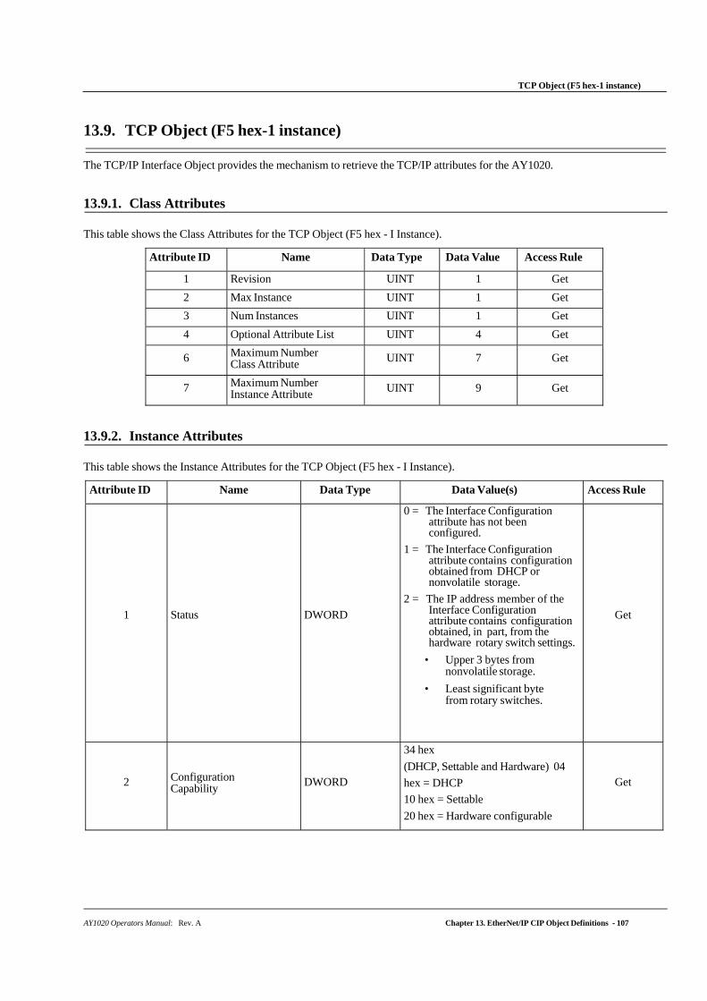
AY1020 Operators Manual: Rev. A Chapter 13. EtherNet/IP CIP Object Definitions - 107
TCP Object (F5 hex-1 instance)
13.9. TCP Object (F5 hex-1 instance)
The TCP/IP Interface Object provides the mechanism to retrieve the TCP/IP attributes for the AY1020.
13.9.1. Class Attributes
This table shows the Class Attributes for the TCP Object (F5 hex - I Instance).
Attribute ID Name Data Type Data Value Access Rule
1 Revision UINT 1 Get
2 Max Instance UINT 1 Get
3 Num Instances UINT 1 Get
4 Optional Attribute List UINT 4 Get
6 Maximum Number Class Attribute UINT 7 Get
7 Maximum Number Instance Attribute UINT 9 Get
13.9.2. Instance Attributes
This table shows the Instance Attributes for the TCP Object (F5 hex - I Instance).
Attribute ID Name Data Type Data Value(s) Access Rule
1
Status
DWORD
0 = The Interface Configuration attribute has not been configured.
1 = The Interface Configuration attribute contains configuration obtained from DHCP or nonvolatile storage.
2 = The IP address member of the Interface Configuration attribute contains configuration obtained, in part, from the hardware rotary switch settings.
• Upper 3 bytes from nonvolatile storage.
• Least significant byte from rotary switches.
Get
2
Configuration Capability
DWORD
34 hex
(DHCP, Settable and Hardware) 04
hex = DHCP
10 hex = Settable
20 hex = Hardware configurable
Get
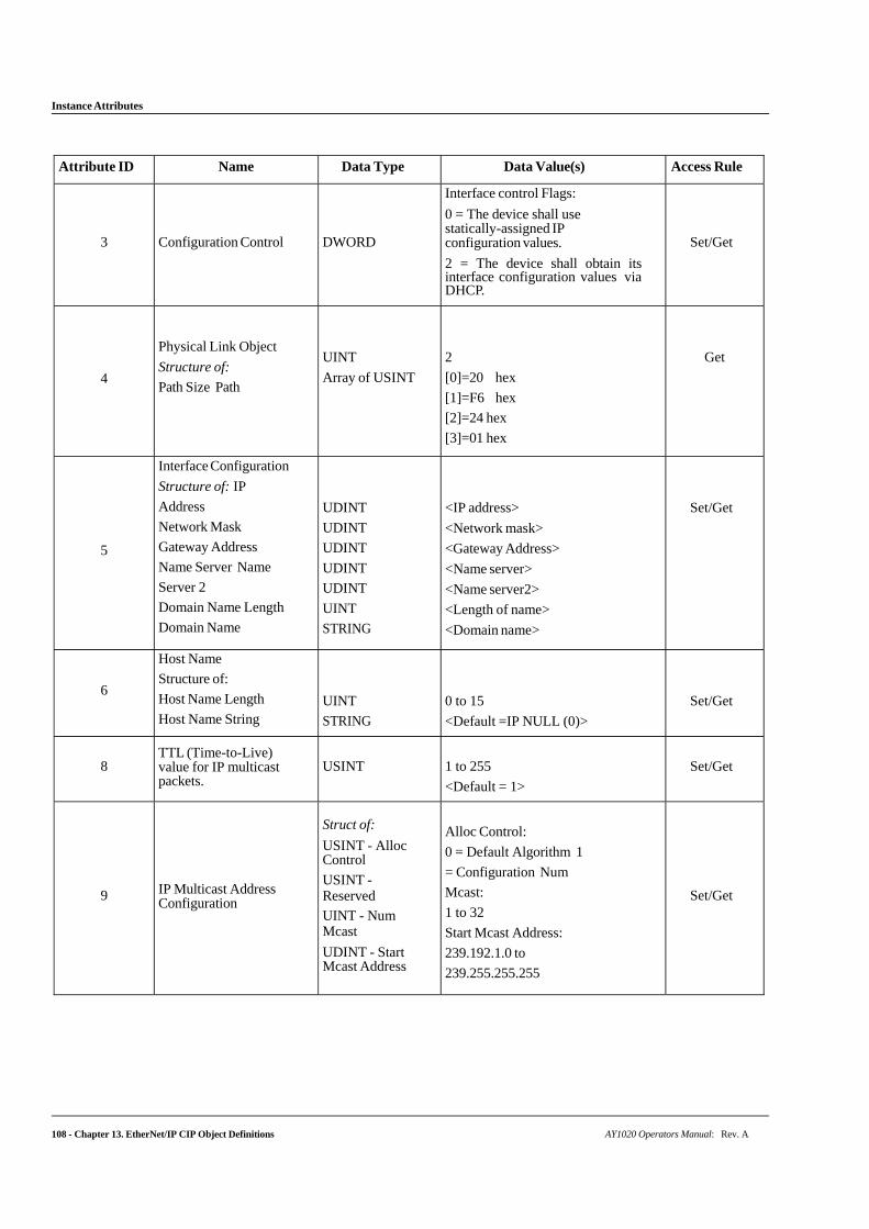
108 - Chapter 13. EtherNet/IP CIP Object Definitions AY1020 Operators Manual: Rev. A
Instance Attributes
Attribute ID Name Data Type Data Value(s) Access Rule
3
Configuration Control
DWORD
Interface control Flags:
0 = The device shall use statically-assigned IP configuration values.
2 = The device shall obtain its interface configuration values via DHCP.
Set/Get
4
Physical Link Object
Structure of:
Path Size Path
UINT
Array of USINT
2
[0]=20 hex
[1]=F6 hex
[2]=24 hex
[3]=01 hex
Get
5
Interface Configuration
Structure of: IP
Address
Network Mask
Gateway Address
Name Server Name
Server 2
Domain Name Length
Domain Name
UDINT
UDINT
UDINT
UDINT
UDINT
UINT
STRING
<IP address>
<Network mask>
<Gateway Address>
<Name server>
<Name server2>
<Length of name>
<Domain name>
Set/Get
6
Host Name
Structure of:
Host Name Length
Host Name String
UINT
STRING
0 to 15
<Default =IP NULL (0)>
Set/Get
8
TTL (Time-to-Live) value for IP multicast packets.
USINT
1 to 255
<Default = 1>
Set/Get
9
IP Multicast Address Configuration
Struct of:
USINT - Alloc Control
USINT - Reserved
UINT - Num Mcast
UDINT - Start Mcast Address
Alloc Control:
0 = Default Algorithm 1
= Configuration Num
Mcast:
1 to 32
Start Mcast Address:
239.192.1.0 to
239.255.255.255
Set/Get
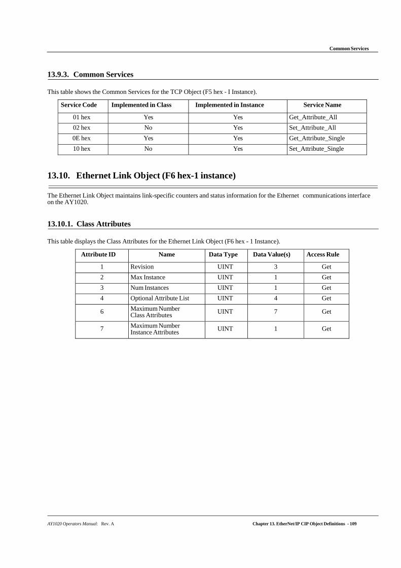
AY1020 Operators Manual: Rev. A Chapter 13. EtherNet/IP CIP Object Definitions - 109
Common Services
13.9.3. Common Services
This table shows the Common Services for the TCP Object (F5 hex - I Instance).
Service Code Implemented in Class Implemented in Instance Service Name
01 hex Yes Yes Get_Attribute_All
02 hex No Yes Set_Attribute_All
0E hex Yes Yes Get_Attribute_Single
10 hex No Yes Set_Attribute_Single
13.10. Ethernet Link Object (F6 hex-1 instance)
The Ethernet Link Object maintains link-specific counters and status information for the Ethernet communications interface on the AY1020.
13.10.1. Class Attributes
This table displays the Class Attributes for the Ethernet Link Object (F6 hex - 1 Instance).
Attribute ID Name Data Type Data Value(s) Access Rule
1 Revision UINT 3 Get
2 Max Instance UINT 1 Get
3 Num Instances UINT 1 Get
4 Optional Attribute List UINT 4 Get
6 Maximum Number Class Attributes UINT 7 Get
7 Maximum Number Instance Attributes UINT 1 Get
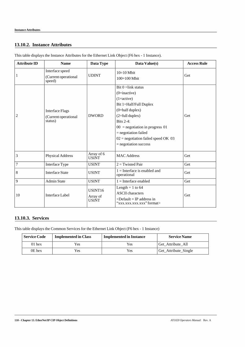
Instance Attributes
110 - Chapter 13. EtherNet/IP CIP Object Definitions AY1020 Operators Manual: Rev. A
13.10.2. Instance Attributes
This table displays the Instance Attributes for the Ethernet Link Object (F6 hex - 1 Instance).
Attribute ID Name Data Type Data Value(s) Access Rule
1
Interface speed
(Current operational speed)
UDINT
10=10 Mbit
100=100 Mbit
Get
2
Interface Flags
(Current operational status)
DWORD
Bit 0 =link status
(0=inactive)
(1=active)
Bit 1=Half/Full Duplex
(0=half duplex)
(2=full duplex)
Bits 2-4:
00 = negotiation in progress 01
= negotiation failed
02 = negotiation failed speed OK 03
= negotiation success
Get
3 Physical Address Array of 6 USINT MAC Address Get
7 Interface Type USINT 2 = Twisted Pair Get
8 Interface State USINT 1 = Interface is enabled and operational Get
9 Admin State USINT 1 = Interface enabled Get
10
Interface Label USINT16
Array of USINT
Length = 1 to 64
ASCII characters
<Default = IP address in “xxx.xxx.xxx.xxx” format>
Get
13.10.3. Services
This table displays the Common Services for the Ethernet Link Object (F6 hex - 1 Instance)
Service Code Implemented in Class Implemented in Instance Service Name
01 hex Yes Yes Get_Attribute_All
0E hex Yes Yes Get_Attribute_Single
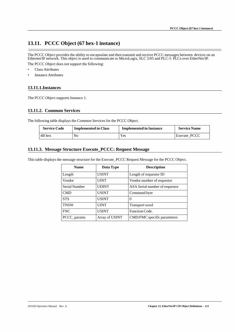
AY1020 Operators Manual: Rev. A Chapter 13. EtherNet/IP CIP Object Definitions - 111
PCCC Object (67 hex-1 instance)
13.11. PCCC Object (67 hex-1 instance)
The PCCC Object provides the ability to encapsulate and then transmit and receive PCCC messages between devices on an Ethernet/IP network. This object is used to communicate to MicroLogix, SLC 5/05 and PLC-5 PLCs over EtherNet/IP.
The PCCC Object does not support the following:
• Class Attributes
• Instance Attributes
13.11.1.Instances
The PCCC Object supports Instance 1.
13.11.2. Common Services
The following table displays the Common Services for the PCCC Object.
Service Code Implemented in Class Implemented in Instance Service Name
4B hex No Yes Execute_PCCC
13.11.3. Message Structure Execute_PCCC: Request Message
This table displays the message structure for the Execute_PCCC Request Message for the PCCC Object.
Name Data Type Description
Length USINT Length of requestor ID
Vendor UINT Vendor number of requestor
Serial Number UDINT ASA Serial number of requestor
CMD USINT Command byte
STS USINT 0
TNSW UINT Transport word
FNC USINT Function Code.
PCCC_params Array of USINT CMD/FMC specific parameters
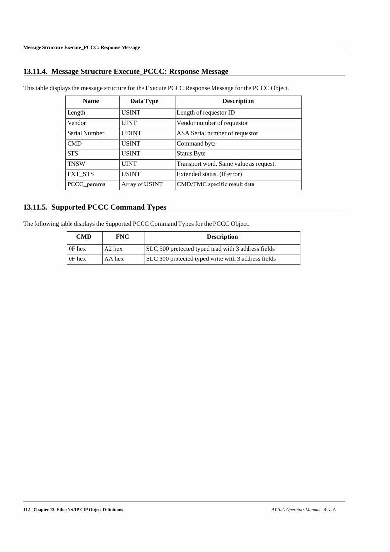
Message Structure Execute_PCCC: Response Message
112 - Chapter 13. EtherNet/IP CIP Object Definitions AY1020 Operators Manual: Rev. A
13.11.4. Message Structure Execute_PCCC: Response Message
This table displays the message structure for the Execute PCCC Response Message for the PCCC Object.
Name Data Type Description
Length USINT Length of requestor ID
Vendor UINT Vendor number of requestor
Serial Number UDINT ASA Serial number of requestor
CMD USINT Command byte
STS USINT Status Byte
TNSW UINT Transport word. Same value as request.
EXT_STS USINT Extended status. (If error)
PCCC_params Array of USINT CMD/FMC specific result data
13.11.5. Supported PCCC Command Types
The following table displays the Supported PCCC Command Types for the PCCC Object.
CMD FNC Description
0F hex A2 hex SLC 500 protected typed read with 3 address fields
0F hex AA hex SLC 500 protected typed write with 3 address fields
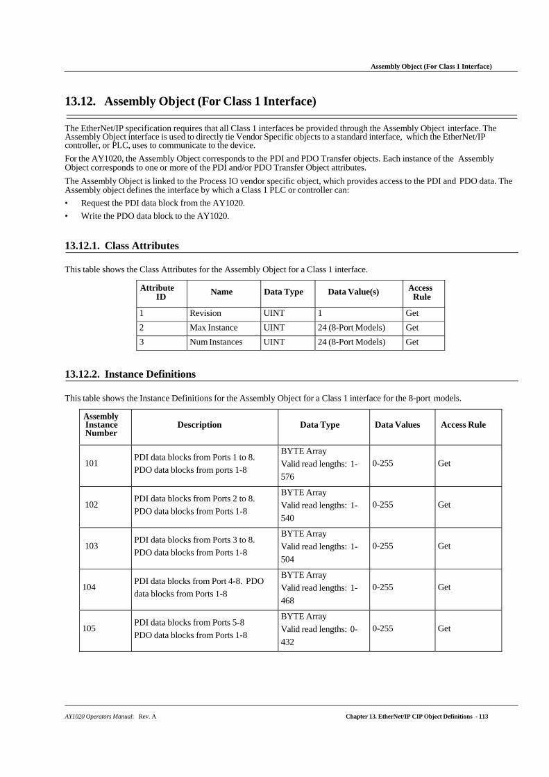
AY1020 Operators Manual: Rev. A Chapter 13. EtherNet/IP CIP Object Definitions - 113
Assembly Object (For Class 1 Interface)
13.12. Assembly Object (For Class 1 Interface)
The EtherNet/IP specification requires that all Class 1 interfaces be provided through the Assembly Object interface. The Assembly Object interface is used to directly tie Vendor Specific objects to a standard interface, which the EtherNet/IP controller, or PLC, uses to communicate to the device.
For the AY1020, the Assembly Object corresponds to the PDI and PDO Transfer objects. Each instance of the Assembly Object corresponds to one or more of the PDI and/or PDO Transfer Object attributes.
The Assembly Object is linked to the Process IO vendor specific object, which provides access to the PDI and PDO data. The Assembly object defines the interface by which a Class 1 PLC or controller can:
• Request the PDI data block from the AY1020.
• Write the PDO data block to the AY1020.
13.12.1. Class Attributes
This table shows the Class Attributes for the Assembly Object for a Class 1 interface.
Attribute ID
Name Data Type Data Value(s) Access Rule
1 Revision UINT 1 Get
2 Max Instance UINT 24 (8-Port Models) Get
3 Num Instances UINT 24 (8-Port Models) Get
13.12.2. Instance Definitions
This table shows the Instance Definitions for the Assembly Object for a Class 1 interface for the 8-port models.
Assembly Instance Number
Description
Data Type
Data Values
Access Rule
101
PDI data blocks from Ports 1 to 8.
PDO data blocks from ports 1-8
BYTE Array
Valid read lengths: 1-
576
0-255
Get
102
PDI data blocks from Ports 2 to 8.
PDO data blocks from Ports 1-8
BYTE Array
Valid read lengths: 1-
540
0-255
Get
103
PDI data blocks from Ports 3 to 8.
PDO data blocks from Ports 1-8
BYTE Array
Valid read lengths: 1-
504
0-255
Get
104
PDI data blocks from Port 4-8. PDO
data blocks from Ports 1-8
BYTE Array
Valid read lengths: 1-
468
0-255
Get
105
PDI data blocks from Ports 5-8
PDO data blocks from Ports 1-8
BYTE Array
Valid read lengths: 0-
432
0-255
Get
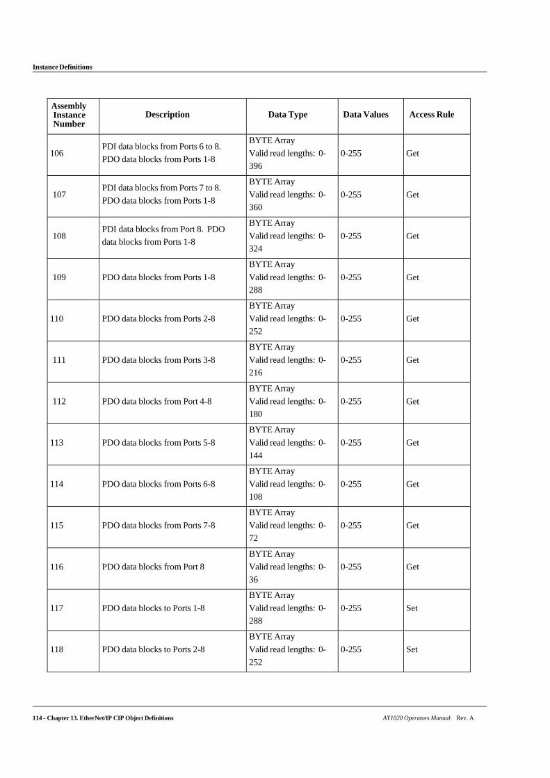
114 - Chapter 13. EtherNet/IP CIP Object Definitions AY1020 Operators Manual: Rev. A
Instance Definitions
Assembly Instance Number
Description
Data Type
Data Values
Access Rule
106
PDI data blocks from Ports 6 to 8.
PDO data blocks from Ports 1-8
BYTE Array
Valid read lengths: 0-
396
0-255
Get
107
PDI data blocks from Ports 7 to 8.
PDO data blocks from Ports 1-8
BYTE Array
Valid read lengths: 0-
360
0-255
Get
108
PDI data blocks from Port 8. PDO
data blocks from Ports 1-8
BYTE Array
Valid read lengths: 0-
324
0-255
Get
109
PDO data blocks from Ports 1-8
BYTE Array
Valid read lengths: 0-
288
0-255
Get
110
PDO data blocks from Ports 2-8
BYTE Array
Valid read lengths: 0-
252
0-255
Get
111
PDO data blocks from Ports 3-8
BYTE Array
Valid read lengths: 0-
216
0-255
Get
112
PDO data blocks from Port 4-8
BYTE Array
Valid read lengths: 0-
180
0-255
Get
113
PDO data blocks from Ports 5-8
BYTE Array
Valid read lengths: 0-
144
0-255
Get
114
PDO data blocks from Ports 6-8
BYTE Array
Valid read lengths: 0-
108
0-255
Get
115
PDO data blocks from Ports 7-8
BYTE Array
Valid read lengths: 0-
72
0-255
Get
116
PDO data blocks from Port 8
BYTE Array
Valid read lengths: 0-
36
0-255
Get
117
PDO data blocks to Ports 1-8
BYTE Array
Valid read lengths: 0-
288
0-255
Set
118
PDO data blocks to Ports 2-8
BYTE Array
Valid read lengths: 0-
252
0-255
Set
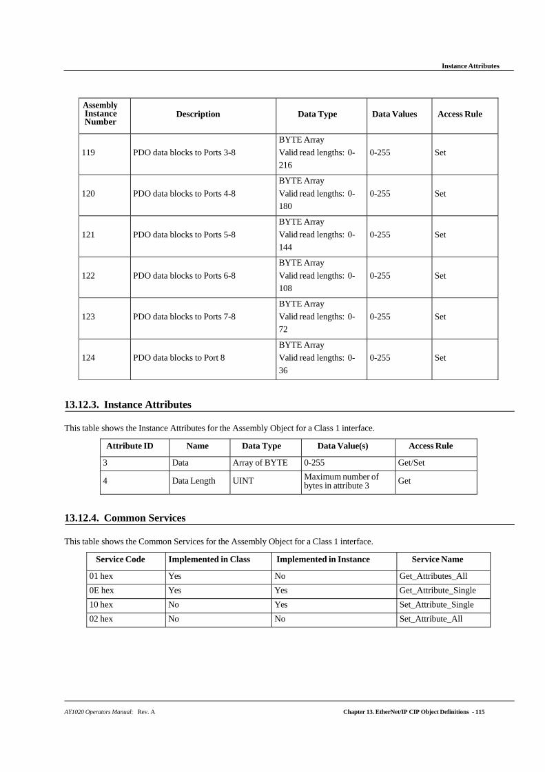
AY1020 Operators Manual: Rev. A Chapter 13. EtherNet/IP CIP Object Definitions - 115
Instance Attributes
Assembly Instance Number
Description
Data Type
Data Values
Access Rule
119
PDO data blocks to Ports 3-8
BYTE Array
Valid read lengths: 0-
216
0-255
Set
120
PDO data blocks to Ports 4-8
BYTE Array
Valid read lengths: 0-
180
0-255
Set
121
PDO data blocks to Ports 5-8
BYTE Array
Valid read lengths: 0-
144
0-255
Set
122
PDO data blocks to Ports 6-8
BYTE Array
Valid read lengths: 0-
108
0-255
Set
123
PDO data blocks to Ports 7-8
BYTE Array
Valid read lengths: 0-
72
0-255
Set
124
PDO data blocks to Port 8
BYTE Array
Valid read lengths: 0-
36
0-255
Set
13.12.3. Instance Attributes
This table shows the Instance Attributes for the Assembly Object for a Class 1 interface.
Attribute ID Name Data Type Data Value(s) Access Rule
3 Data Array of BYTE 0-255 Get/Set
4 Data Length UINT Maximum number of bytes in attribute 3 Get
13.12.4. Common Services
This table shows the Common Services for the Assembly Object for a Class 1 interface.
Service Code Implemented in Class Implemented in Instance Service Name
01 hex Yes No Get_Attributes_All
0E hex Yes Yes Get_Attribute_Single
10 hex No Yes Set_Attribute_Single
02 hex No No Set_Attribute_All
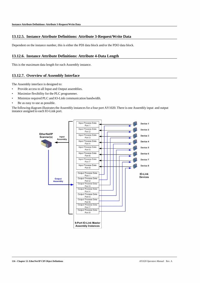
116 - Chapter 13. EtherNet/IP CIP Object Definitions AY1020 Operators Manual: Rev. A
Instance Attribute Definitions: Attribute 3-Request/Write Data
13.12.5. Instance Attribute Definitions: Attribute 3-Request/Write Data
Dependent on the instance number, this is either the PDI data block and/or the PDO data block.
13.12.6. Instance Attribute Definitions: Attribute 4-Data Length
This is the maximum data length for each Assembly instance.
13.12.7. Overview of Assembly Interface
The Assembly interface is designed to:
• Provide access to all Input and Output assemblies.
• Maximize flexibility for the PLC programmer.
• Minimize required PLC and IO-Link communication bandwidth.
• Be as easy to use as possible.
The following diagram illustrates the Assembly instances for a four port AY1020. There is one Assembly input and output instance assigned to each IO-Link port.
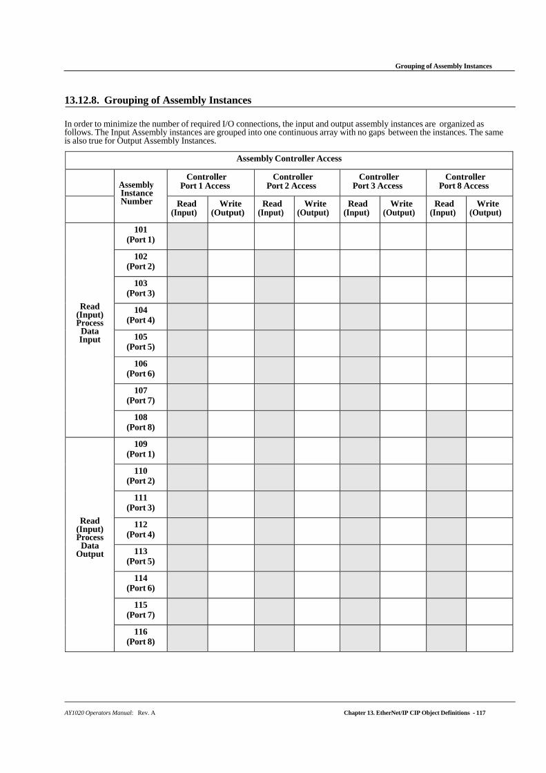
AY1020 Operators Manual: Rev. A Chapter 13. EtherNet/IP CIP Object Definitions - 117
Grouping of Assembly Instances
13.12.8. Grouping of Assembly Instances
In order to minimize the number of required I/O connections, the input and output assembly instances are organized as follows. The Input Assembly instances are grouped into one continuous array with no gaps between the instances. The same is also true for Output Assembly Instances.
Assembly Controller Access
Assembly Instance Number
Controller Port 1 Access
Controller Port 2 Access
Controller Port 3 Access
Controller Port 8 Access
Read (Input)
Write (Output)
Read (Input)
Write (Output)
Read (Input)
Write (Output)
Read (Input)
Write (Output)
Read (Input) Process
Data Input
101 (Port 1)
102 (Port 2)
103 (Port 3)
104 (Port 4)
105 (Port 5)
106 (Port 6)
107 (Port 7)
108 (Port 8)
Read (Input) Process
Data Output
109 (Port 1)
110 (Port 2)
111 (Port 3)
112 (Port 4)
113 (Port 5)
114 (Port 6)
115 (Port 7)
116 (Port 8)
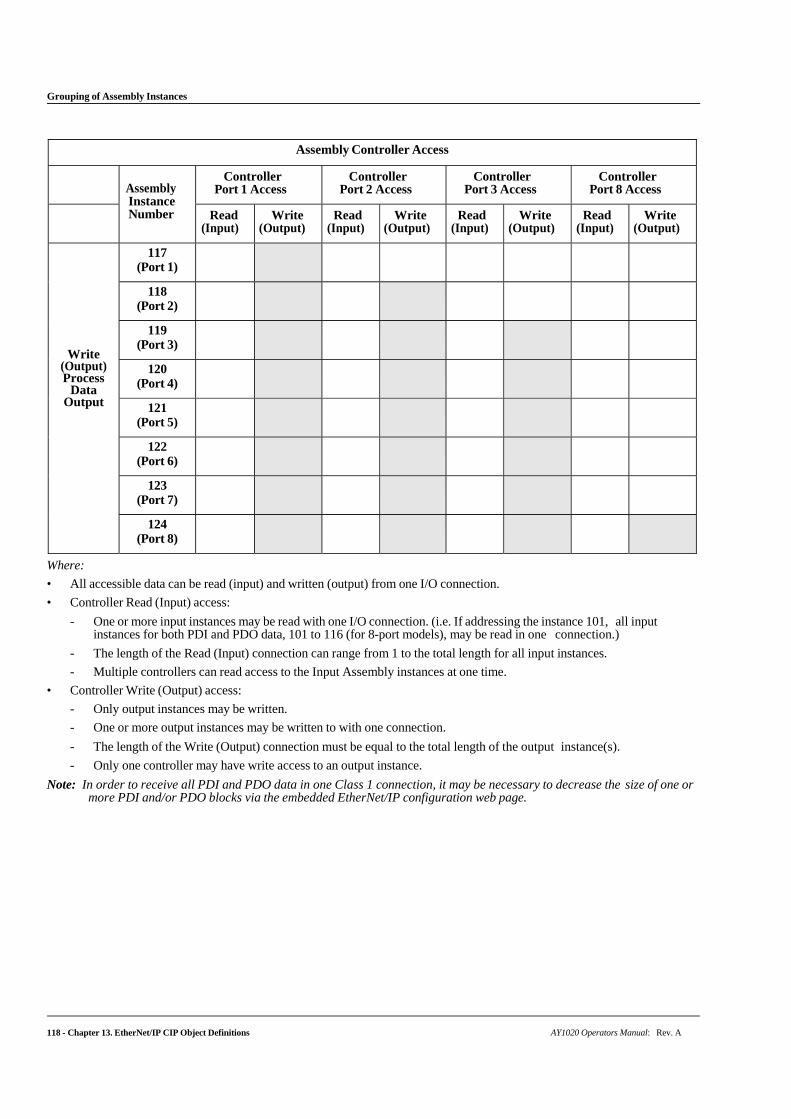
118 - Chapter 13. EtherNet/IP CIP Object Definitions AY1020 Operators Manual: Rev. A
Grouping of Assembly Instances
Assembly Controller Access
Assembly Instance Number
Controller Port 1 Access
Controller Port 2 Access
Controller Port 3 Access
Controller Port 8 Access
Read (Input)
Write (Output)
Read (Input)
Write (Output)
Read (Input)
Write (Output)
Read (Input)
Write (Output)
Write (Output) Process
Data Output
117 (Port 1)
118 (Port 2)
119 (Port 3)
120 (Port 4)
121 (Port 5)
122 (Port 6)
123 (Port 7)
124 (Port 8)
Where:
• All accessible data can be read (input) and written (output) from one I/O connection.
• Controller Read (Input) access:
- One or more input instances may be read with one I/O connection. (i.e. If addressing the instance 101, all input instances for both PDI and PDO data, 101 to 116 (for 8-port models), may be read in one connection.)
- The length of the Read (Input) connection can range from 1 to the total length for all input instances.
- Multiple controllers can read access to the Input Assembly instances at one time.
• Controller Write (Output) access:
- Only output instances may be written.
- One or more output instances may be written to with one connection.
- The length of the Write (Output) connection must be equal to the total length of the output instance(s).
- Only one controller may have write access to an output instance.
Note: In order to receive all PDI and PDO data in one Class 1 connection, it may be necessary to decrease the size of one or more PDI and/or PDO blocks via the embedded EtherNet/IP configuration web page.

AY1020 Operators Manual: Rev. A Chapter 14. SLC/PLC-5/MicroLogix Interface - 119
Chapter 14. SLC/PLC-5/MicroLogix Interface
The AY1020 provides support for the SLC, PLC-5 and MicroLogix PLCs. The following features are supported:
• Rx PDI data, both Polling and Write-to-File modes.
• Tx PDO data, both PLC-Writes and Read-From-File modes.
• PCCC based messages transferred by means of the PCCC CIP object, including:
- SLC Typed Read Message
- SLC Typed Write Message
- PLC-5 Typed Read Message (Logical ASCII address format)
- PLC-5 Typed Write Message (Logical ASCII address format)
• Receive, transmit and statistics data.
• Standard PLC-5/SLC file naming conventions.
• Controlled message rate to the PLC when operating in the Write-to-File receive method. This is accomplished by setting the Maximum PLC Update Rate.
The primary differences between the PLC-5/SLC interface and the ControlLogix interfaces are:
• Since the PLC-5 and SLC PLCs operate on a file memory system, the PLC-5/SLC interface provides Write-to-File and Read-from-File communication methods in place of Write-to-Tag and Read-from-Tag communication methods. The Write-to-File methods operate in a very similar manner to the Write-to-Tag method available for the ControlLogix family of PLCs.
• Polling is performed through the PLC-5/SLC specific messages instead of accessing the Serial Port Data Transfer object.
• When configuring the AY1020 to operate in Write-to-File or Read-from-File, enter the file name starting with an N (i.e. N10:0).
Note: While ControlLogix PLCs support the SLC and PLC-5 messages, using those messages on ControlLogix PLCs is not recommended due to data size and performance considerations.
14.1. Requirements
Your PLC-5/SLC/MicroLogix PLC must support:
• MultipHop
• ControlLogix devices
• EtherNet/IP
The following tables list PLCs that support EtherNet/IP and the required firmware version for each PLC.
Note: Older versions of the PLC firmware may or may not provide EtherNet/IP functionality. You must verify that an older version of the PLC firmware provides EtherNet/IP functionality before you can use it with AY1020.
If you need to update your PLC firmware, contact your Rockwell distributor.
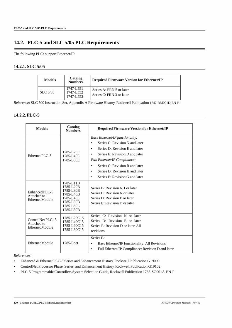
120 - Chapter 14. SLC/PLC-5/MicroLogix Interface AY1020 Operators Manual: Rev. A
PLC-5 and SLC 5/05 PLC Requirements
14.2. PLC-5 and SLC 5/05 PLC Requirements
The following PLCs support Ethernet/IP.
14.2.1. SLC 5/05
Models Catalog Numbers Required Firmware Version for Ethernet/IP
SLC 5/05 1747-L551 1747-L552 1747-L553
Series A: FRN 5 or later Series C: FRN 3 or later
Reference: SLC 500 Instruction Set, Appendix A Firmware History, Rockwell Publication 1747-RM001D-EN-P.
14.2.2. PLC-5
Models Catalog Numbers Required Firmware Version for Ethernet/IP
Ethernet PLC-5
1785-L20E 1785-L40E 1785-L80E
Base Ethernet/IP functionality:
• Series C: Revision N and later
• Series D: Revision E and later
• Series E: Revision D and later
Full Ethernet/IP Compliance:
• Series C: Revision R and later
• Series D: Revision H and later
• Series E: Revision G and later
Enhanced PLC-5 Attached to Ethernet Module
1785-L11B Series B: Revision N.1 or later Series C: Revision N or later Series D: Revision E or later Series E: Revision D or later
1785-L20B 1785-L30B 1785-L40B 1785-L40L 1785-L60B 1785-L60L 1785-L80B
ControlNet PLC- 5 Attached to Ethernet Module
1785-L20C15 1785-L40C15 1785-L60C15 1785-L80C15
Series C: Revision N or later Series D: Revision E or later Series E: Revision D or later All revisions
Ethernet Module
1785-Enet
Series B:
• Base Ethernet/IP functionality: All Revisions
• Full Ethernet/IP Compliance: Revision D and later
References:
• Enhanced & Ethernet PLC-5 Series and Enhancement History, Rockwell Publication G19099
• ControlNet Processor Phase, Series, and Enhancement History, Rockwell Publication G19102
• PLC-5 Programmable Controllers System Selection Guide, Rockwell Publication 1785-SG001A-EN-P
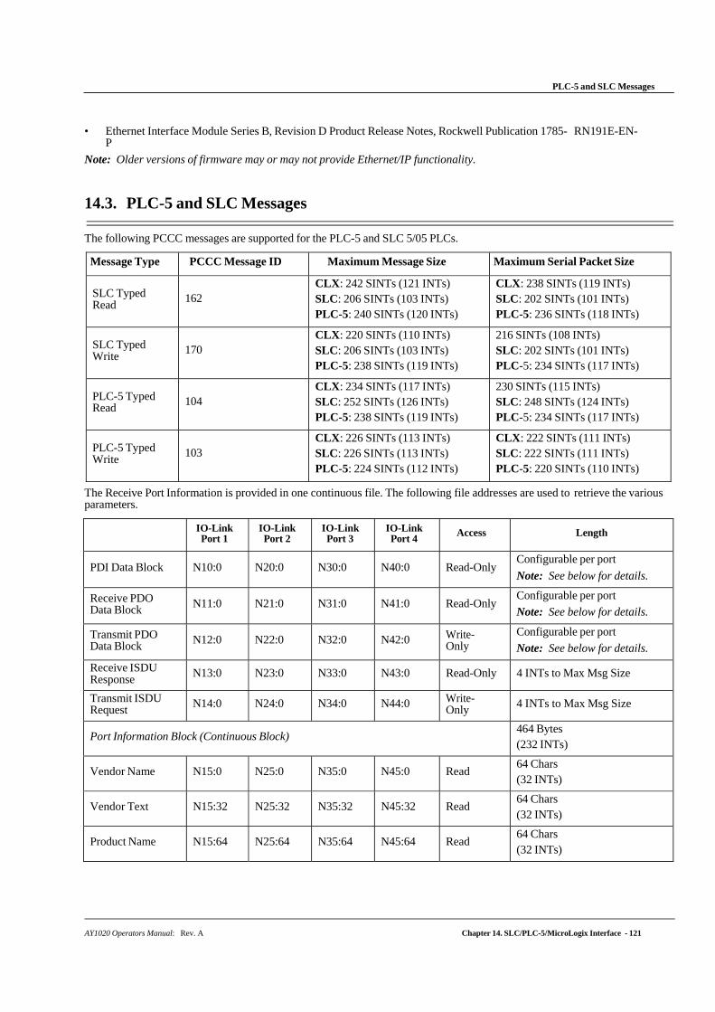
AY1020 Operators Manual: Rev. A Chapter 14. SLC/PLC-5/MicroLogix Interface - 121
PLC-5 and SLC Messages
• Ethernet Interface Module Series B, Revision D Product Release Notes, Rockwell Publication 1785- RN191E-EN-P
Note: Older versions of firmware may or may not provide Ethernet/IP functionality.
14.3. PLC-5 and SLC Messages
The following PCCC messages are supported for the PLC-5 and SLC 5/05 PLCs.
Message Type PCCC Message ID Maximum Message Size Maximum Serial Packet Size
SLC Typed Read
162
CLX: 242 SINTs (121 INTs) SLC: 206 SINTs (103 INTs) PLC-5: 240 SINTs (120 INTs)
CLX: 238 SINTs (119 INTs) SLC: 202 SINTs (101 INTs) PLC-5: 236 SINTs (118 INTs)
SLC Typed Write
170
CLX: 220 SINTs (110 INTs) SLC: 206 SINTs (103 INTs) PLC-5: 238 SINTs (119 INTs)
216 SINTs (108 INTs) SLC: 202 SINTs (101 INTs) PLC-5: 234 SINTs (117 INTs)
PLC-5 Typed Read
104
CLX: 234 SINTs (117 INTs) SLC: 252 SINTs (126 INTs) PLC-5: 238 SINTs (119 INTs)
230 SINTs (115 INTs) SLC: 248 SINTs (124 INTs) PLC-5: 234 SINTs (117 INTs)
PLC-5 Typed Write
103
CLX: 226 SINTs (113 INTs) SLC: 226 SINTs (113 INTs) PLC-5: 224 SINTs (112 INTs)
CLX: 222 SINTs (111 INTs) SLC: 222 SINTs (111 INTs) PLC-5: 220 SINTs (110 INTs)
The Receive Port Information is provided in one continuous file. The following file addresses are used to retrieve the various parameters.
IO-Link Port 1
IO-Link Port 2
IO-Link Port 3
IO-Link Port 4
Access Length
PDI Data Block N10:0 N20:0 N30:0 N40:0 Read-Only Configurable per port
Note: See below for details.
Receive PDO Data Block N11:0 N21:0 N31:0 N41:0 Read-Only
Configurable per port
Note: See below for details.
Transmit PDO Data Block N12:0 N22:0 N32:0 N42:0 Write-
Only Configurable per port
Note: See below for details.
Receive ISDU Response N13:0 N23:0 N33:0 N43:0 Read-Only 4 INTs to Max Msg Size
Transmit ISDU Request N14:0 N24:0 N34:0 N44:0 Write-
Only 4 INTs to Max Msg Size
Port Information Block (Continuous Block) 464 Bytes (232 INTs)
Vendor Name N15:0 N25:0 N35:0 N45:0 Read 64 Chars (32 INTs)
Vendor Text N15:32 N25:32 N35:32 N45:32 Read 64 Chars (32 INTs)
Product Name N15:64 N25:64 N35:64 N45:64 Read 64 Chars (32 INTs)
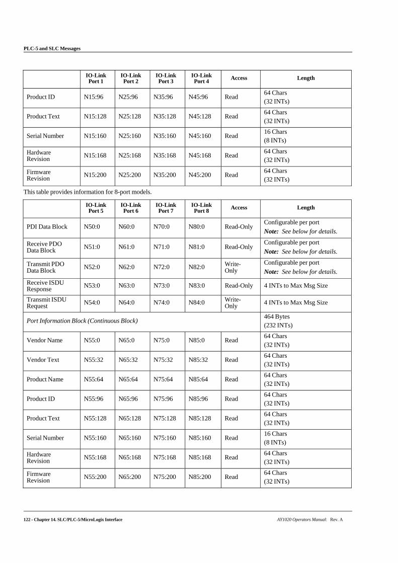
122 - Chapter 14. SLC/PLC-5/MicroLogix Interface AY1020 Operators Manual: Rev. A
PLC-5 and SLC Messages
IO-Link
Port 1 IO-Link Port 2
IO-Link Port 3
IO-Link Port 4
Access Length
Product ID N15:96 N25:96 N35:96 N45:96 Read 64 Chars (32 INTs)
Product Text N15:128 N25:128 N35:128 N45:128 Read 64 Chars (32 INTs)
Serial Number N15:160 N25:160 N35:160 N45:160 Read 16 Chars (8 INTs)
Hardware Revision N15:168 N25:168 N35:168 N45:168 Read
64 Chars (32 INTs)
Firmware Revision N15:200 N25:200 N35:200 N45:200 Read
64 Chars (32 INTs)
This table provides information for 8-port models.
IO-Link Port 5
IO-Link Port 6
IO-Link Port 7
IO-Link Port 8
Access Length
PDI Data Block N50:0 N60:0 N70:0 N80:0 Read-Only Configurable per port
Note: See below for details.
Receive PDO Data Block N51:0 N61:0 N71:0 N81:0 Read-Only
Configurable per port
Note: See below for details.
Transmit PDO Data Block N52:0 N62:0 N72:0 N82:0 Write-
Only Configurable per port
Note: See below for details.
Receive ISDU Response N53:0 N63:0 N73:0 N83:0 Read-Only 4 INTs to Max Msg Size
Transmit ISDU Request N54:0 N64:0 N74:0 N84:0 Write-
Only 4 INTs to Max Msg Size
Port Information Block (Continuous Block) 464 Bytes (232 INTs)
Vendor Name N55:0 N65:0 N75:0 N85:0 Read 64 Chars (32 INTs)
Vendor Text N55:32 N65:32 N75:32 N85:32 Read 64 Chars (32 INTs)
Product Name N55:64 N65:64 N75:64 N85:64 Read 64 Chars (32 INTs)
Product ID N55:96 N65:96 N75:96 N85:96 Read 64 Chars (32 INTs)
Product Text N55:128 N65:128 N75:128 N85:128 Read 64 Chars (32 INTs)
Serial Number N55:160 N65:160 N75:160 N85:160 Read 16 Chars (8 INTs)
Hardware Revision N55:168 N65:168 N75:168 N85:168 Read
64 Chars (32 INTs)
Firmware Revision N55:200 N65:200 N75:200 N85:200 Read
64 Chars (32 INTs)
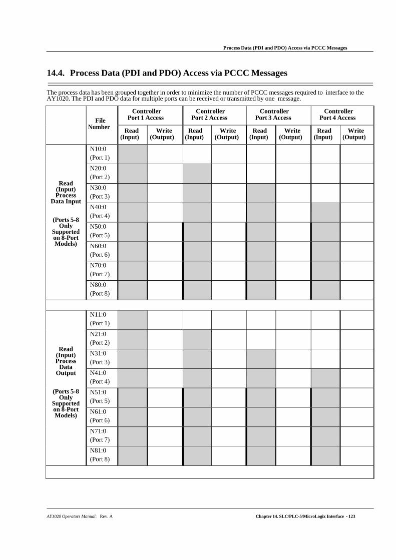
AY1020 Operators Manual: Rev. A Chapter 14. SLC/PLC-5/MicroLogix Interface - 123
Process Data (PDI and PDO) Access via PCCC Messages
14.4. Process Data (PDI and PDO) Access via PCCC Messages
The process data has been grouped together in order to minimize the number of PCCC messages required to interface to the AY1020. The PDI and PDO data for multiple ports can be received or transmitted by one message.
File Number
Controller Port 1 Access
Controller Port 2 Access
Controller Port 3 Access
Controller Port 4 Access
Read (Input)
Write (Output)
Read (Input)
Write (Output)
Read (Input)
Write (Output)
Read (Input)
Write (Output)
Read (Input) Process
Data Input
(Ports 5-8 Only
Supported on 8-Port Models)
N10:0 (Port 1)
N20:0 (Port 2)
N30:0 (Port 3)
N40:0 (Port 4)
N50:0 (Port 5)
N60:0 (Port 6)
N70:0 (Port 7)
N80:0 (Port 8)
Read (Input) Process
Data Output
(Ports 5-8 Only
Supported on 8-Port Models)
N11:0 (Port 1)
N21:0 (Port 2)
N31:0 (Port 3)
N41:0 (Port 4)
N51:0 (Port 5)
N61:0 (Port 6)
N71:0 (Port 7)
N81:0 (Port 8)
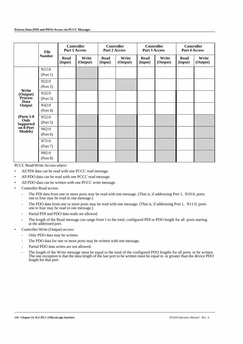
124 - Chapter 14. SLC/PLC-5/MicroLogix Interface AY1020 Operators Manual: Rev. A
Process Data (PDI and PDO) Access via PCCC Messages
File Number
Controller Port 1 Access
Controller Port 2 Access
Controller Port 3 Access
Controller Port 4 Access
Read (Input)
Write (Output)
Read (Input)
Write (Output)
Read (Input)
Write (Output)
Read (Input)
Write (Output)
Write (Output) Process
Data Output
(Ports 5-8 Only
Supported on 8-Port Models)
N12:0 (Port 1)
N22:0 (Port 2)
N32:0 (Port 3)
N42:0 (Port 4)
N52:0 (Port 5)
N62:0 (Port 6)
N72:0 (Port 7)
N82:0 (Port 8)
PCCC Read/Write Access where:
• All PDI data can be read with one PCCC read message.
• All PDO data can be read with one PCCC read message.
• All PDO data can be written with one PCCC write message.
• Controller Read access:
- The PDI data from one or more ports may be read with one message. (That is, if addressing Port 1, N10:0, ports one to four may be read in one message.)
- The PDO data from one or more ports may be read with one message. (That is, if addressing Port 1, N11:0, ports one to four may be read in one message.)
- Partial PDI and PDO data reads are allowed.
- The length of the Read message can range from 1 to the total, configured PDI or PDO length for all ports starting at the addressed port.
• Controller Write (Output) access:
- Only PDO data may be written.
- The PDO data for one or more ports may be written with one message.
- Partial PDO data writes are not allowed.
- The length of the Write message must be equal to the total of the configured PDO lengths for all ports to be written. The one exception is that the data length of the last port to be written must be equal to or greater than the device PDO length for that port.
Chapter 15. EDS Files
AY1020 Operators Manual: Rev. A Chapter 15. EDS Files - 125
This chapter discusses the following topics:
• Downloading the Files
• Adding the AY1020 to RSLinx
• Adding EDS Files to RSLinx on Page 126
15.1. Overview
You do not need to add the AY1020 to RSLinx for normal AY1020-to-PLC communications. However, you can easily add the AY1020 and its associated Electronic Data Sheet (EDS) files to RSLinx.
The files named AY1020_*.ico are icon files and files named AY1020_dd_NNNN-x.xx.eds are ODVA electronic data sheet files where:
• dd is the model name
• NNNN is the product ID number
• x.xx is the version number
15.2. Downloading the Files
You can download the EDS files provided for the AY1020 from the web ifm site.
15.3. Adding the AY1020 to RSLinx
You can use these steps to add the AY1020 to RSLinx.
1. Open RSLinx.
2. Under Communications, select Configure Drivers.
3. Under Available Drivers, select Remote Devices via Linx Gateway.
4. Select Add New.
5. Use the default driver name or type your own driver name and click OK to continue.
6. Type the IP address for the device under Server’s IP Address or Hostname and select OK.
7. Select RSWho to verify that RSLinx can communicate with the AY1020.
Note: A yellow question mark appears by the AY1020(s) in the RSWho window when the associated EDS file(s) are not installed.
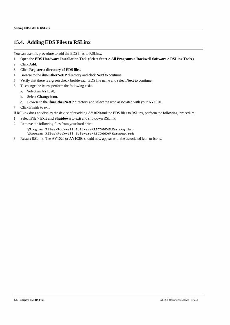
126 - Chapter 15. EDS Files AY1020 Operators Manual: Rev. A
Adding EDS Files to RSLinx
15.4. Adding EDS Files to RSLinx
You can use this procedure to add the EDS files to RSLinx.
1. Open the EDS Hardware Installation Tool. (Select Start > All Programs > Rockwell Software > RSLinx Tools.)
2. Click Add.
3. Click Register a directory of EDS files.
4. Browse to the ifm/EtherNetIP directory and click Next to continue.
5. Verify that there is a green check beside each EDS file name and select Next to continue.
6. To change the icons, perform the following tasks.
a. Select an AY1020.
b. Select Change icon.
c. Browse to the ifm/EtherNetIP directory and select the icon associated with your AY1020.
7. Click Finish to exit.
If RSLinx does not display the device after adding AY1020 and the EDS files to RSLinx, perform the following procedure:
1. Select File > Exit and Shutdown to exit and shutdown RSLinx.
2. Remove the following files from your hard drive:
\Program Files\Rockwell Software\RSCOMMON\Harmony.hrc \Program Files\Rockwell Software\RSCOMMON\Harmony.rsh
3. Restart RSLinx. The AY1020 or AY1020s should now appear with the associated icon or icons.
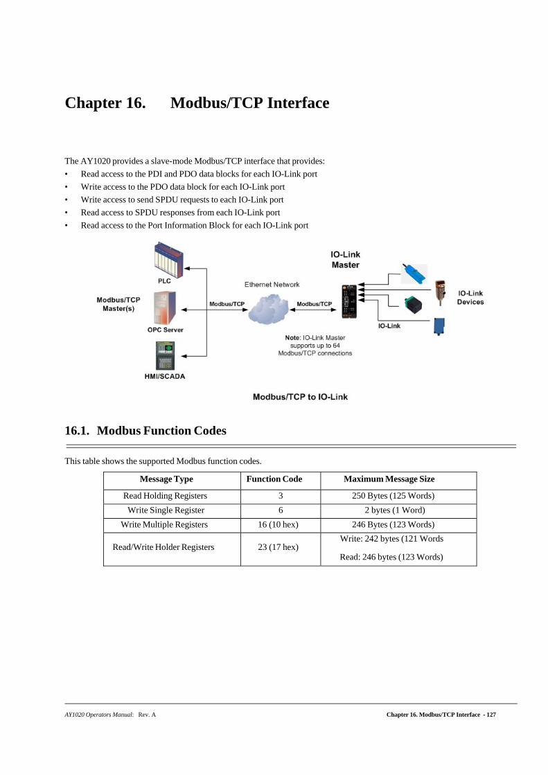
Chapter 16. Modbus/TCP Interface
AY1020 Operators Manual: Rev. A Chapter 16. Modbus/TCP Interface - 127
The AY1020 provides a slave-mode Modbus/TCP interface that provides:
• Read access to the PDI and PDO data blocks for each IO-Link port
• Write access to the PDO data block for each IO-Link port
• Write access to send SPDU requests to each IO-Link port
• Read access to SPDU responses from each IO-Link port
• Read access to the Port Information Block for each IO-Link port
16.1. Modbus Function Codes
This table shows the supported Modbus function codes.
Message Type Function Code Maximum Message Size
Read Holding Registers 3 250 Bytes (125 Words)
Write Single Register 6 2 bytes (1 Word)
Write Multiple Registers 16 (10 hex) 246 Bytes (123 Words)
Read/Write Holder Registers
23 (17 hex) Write: 242 bytes (121 Words
Read: 246 bytes (123 Words)
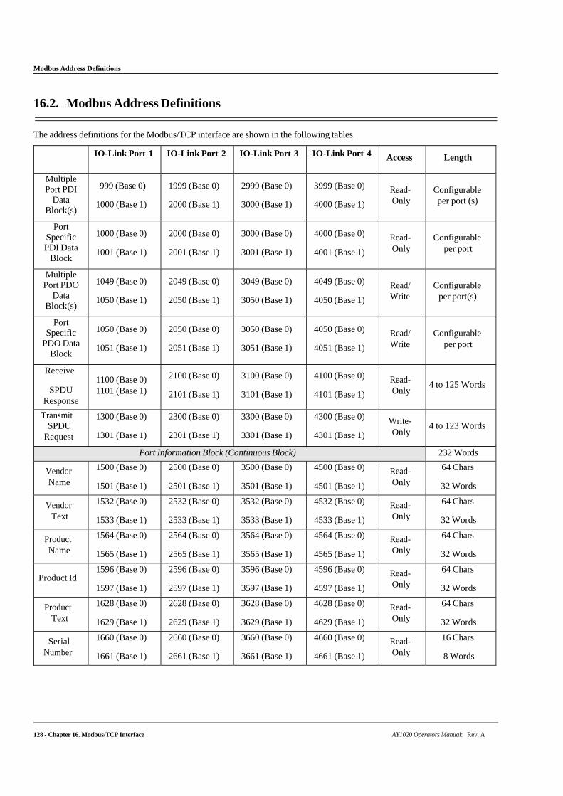
128 - Chapter 16. Modbus/TCP Interface AY1020 Operators Manual: Rev. A
Modbus Address Definitions
16.2. Modbus Address Definitions
The address definitions for the Modbus/TCP interface are shown in the following tables.
IO-Link Port 1 IO-Link Port 2 IO-Link Port 3 IO-Link Port 4 Access Length
Multiple Port PDI
Data Block(s)
999 (Base 0)
1000 (Base 1)
1999 (Base 0)
2000 (Base 1)
2999 (Base 0)
3000 (Base 1)
3999 (Base 0)
4000 (Base 1)
Read- Only
Configurable per port (s)
Port Specific PDI Data
Block
1000 (Base 0)
1001 (Base 1)
2000 (Base 0)
2001 (Base 1)
3000 (Base 0)
3001 (Base 1)
4000 (Base 0)
4001 (Base 1)
Read- Only
Configurable
per port
Multiple Port PDO
Data Block(s)
1049 (Base 0)
1050 (Base 1)
2049 (Base 0)
2050 (Base 1)
3049 (Base 0)
3050 (Base 1)
4049 (Base 0)
4050 (Base 1)
Read/ Write
Configurable
per port(s)
Port Specific
PDO Data Block
1050 (Base 0)
1051 (Base 1)
2050 (Base 0)
2051 (Base 1)
3050 (Base 0)
3051 (Base 1)
4050 (Base 0)
4051 (Base 1)
Read/ Write
Configurable
per port
Receive
SPDU Response
1100 (Base 0) 1101 (Base 1)
2100 (Base 0)
2101 (Base 1)
3100 (Base 0)
3101 (Base 1)
4100 (Base 0)
4101 (Base 1)
Read- Only
4 to 125 Words
Transmit SPDU
Request
1300 (Base 0)
1301 (Base 1)
2300 (Base 0)
2301 (Base 1)
3300 (Base 0)
3301 (Base 1)
4300 (Base 0)
4301 (Base 1)
Write- Only
4 to 123 Words
Port Information Block (Continuous Block) 232 Words
Vendor Name
1500 (Base 0)
1501 (Base 1)
2500 (Base 0)
2501 (Base 1)
3500 (Base 0)
3501 (Base 1)
4500 (Base 0)
4501 (Base 1)
Read- Only
64 Chars
32 Words
Vendor Text
1532 (Base 0)
1533 (Base 1)
2532 (Base 0)
2533 (Base 1)
3532 (Base 0)
3533 (Base 1)
4532 (Base 0)
4533 (Base 1)
Read- Only
64 Chars
32 Words
Product Name
1564 (Base 0)
1565 (Base 1)
2564 (Base 0)
2565 (Base 1)
3564 (Base 0)
3565 (Base 1)
4564 (Base 0)
4565 (Base 1)
Read- Only
64 Chars
32 Words
Product Id 1596 (Base 0)
1597 (Base 1)
2596 (Base 0)
2597 (Base 1)
3596 (Base 0)
3597 (Base 1)
4596 (Base 0)
4597 (Base 1)
Read- Only
64 Chars
32 Words
Product Text
1628 (Base 0)
1629 (Base 1)
2628 (Base 0)
2629 (Base 1)
3628 (Base 0)
3629 (Base 1)
4628 (Base 0)
4629 (Base 1)
Read- Only
64 Chars
32 Words
Serial Number
1660 (Base 0)
1661 (Base 1)
2660 (Base 0)
2661 (Base 1)
3660 (Base 0)
3661 (Base 1)
4660 (Base 0)
4661 (Base 1)
Read- Only
16 Chars
8 Words
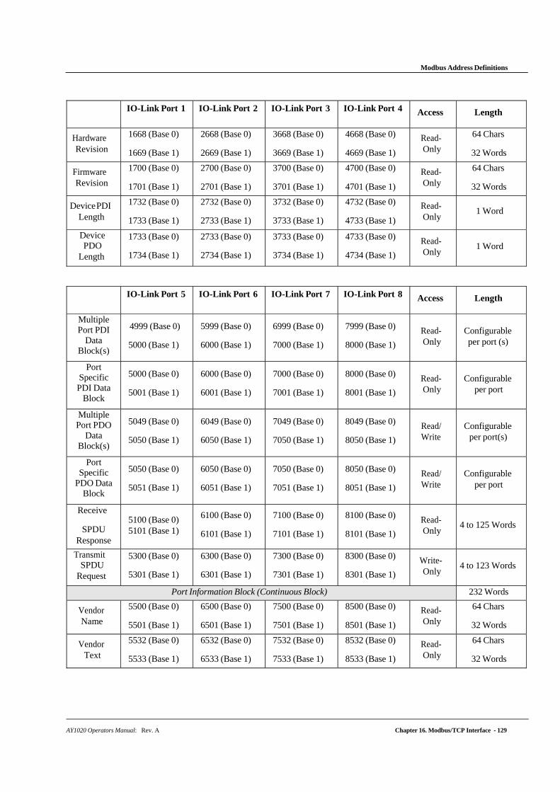
AY1020 Operators Manual: Rev. A Chapter 16. Modbus/TCP Interface - 129
Modbus Address Definitions
IO-Link Port 1 IO-Link Port 2 IO-Link Port 3 IO-Link Port 4 Access Length
Hardware Revision
1668 (Base 0)
1669 (Base 1)
2668 (Base 0)
2669 (Base 1)
3668 (Base 0)
3669 (Base 1)
4668 (Base 0)
4669 (Base 1)
Read- Only
64 Chars
32 Words
Firmware Revision
1700 (Base 0)
1701 (Base 1)
2700 (Base 0)
2701 (Base 1)
3700 (Base 0)
3701 (Base 1)
4700 (Base 0)
4701 (Base 1)
Read- Only
64 Chars
32 Words
Device PDI Length
1732 (Base 0)
1733 (Base 1)
2732 (Base 0)
2733 (Base 1)
3732 (Base 0)
3733 (Base 1)
4732 (Base 0)
4733 (Base 1)
Read- Only
1 Word
Device PDO
Length
1733 (Base 0)
1734 (Base 1)
2733 (Base 0)
2734 (Base 1)
3733 (Base 0)
3734 (Base 1)
4733 (Base 0)
4734 (Base 1)
Read- Only
1 Word
IO-Link Port 5 IO-Link Port 6 IO-Link Port 7 IO-Link Port 8 Access Length
Multiple Port PDI
Data Block(s)
4999 (Base 0)
5000 (Base 1)
5999 (Base 0)
6000 (Base 1)
6999 (Base 0)
7000 (Base 1)
7999 (Base 0)
8000 (Base 1)
Read- Only
Configurable per port (s)
Port Specific PDI Data
Block
5000 (Base 0)
5001 (Base 1)
6000 (Base 0)
6001 (Base 1)
7000 (Base 0)
7001 (Base 1)
8000 (Base 0)
8001 (Base 1)
Read- Only
Configurable
per port
Multiple Port PDO
Data Block(s)
5049 (Base 0)
5050 (Base 1)
6049 (Base 0)
6050 (Base 1)
7049 (Base 0)
7050 (Base 1)
8049 (Base 0)
8050 (Base 1)
Read/ Write
Configurable
per port(s)
Port Specific
PDO Data Block
5050 (Base 0)
5051 (Base 1)
6050 (Base 0)
6051 (Base 1)
7050 (Base 0)
7051 (Base 1)
8050 (Base 0)
8051 (Base 1)
Read/ Write
Configurable
per port
Receive
SPDU Response
5100 (Base 0) 5101 (Base 1)
6100 (Base 0)
6101 (Base 1)
7100 (Base 0)
7101 (Base 1)
8100 (Base 0)
8101 (Base 1)
Read- Only
4 to 125 Words
Transmit SPDU
Request
5300 (Base 0)
5301 (Base 1)
6300 (Base 0)
6301 (Base 1)
7300 (Base 0)
7301 (Base 1)
8300 (Base 0)
8301 (Base 1)
Write- Only
4 to 123 Words
Port Information Block (Continuous Block) 232 Words
Vendor Name
5500 (Base 0)
5501 (Base 1)
6500 (Base 0)
6501 (Base 1)
7500 (Base 0)
7501 (Base 1)
8500 (Base 0)
8501 (Base 1)
Read- Only
64 Chars
32 Words
Vendor Text
5532 (Base 0)
5533 (Base 1)
6532 (Base 0)
6533 (Base 1)
7532 (Base 0)
7533 (Base 1)
8532 (Base 0)
8533 (Base 1)
Read- Only
64 Chars
32 Words
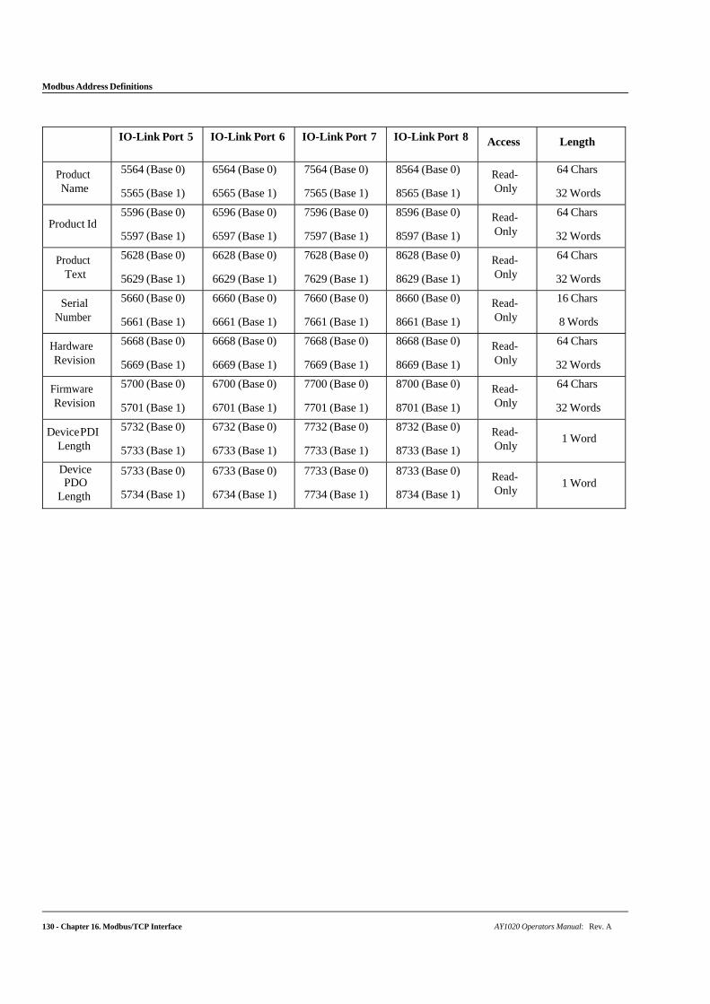
Modbus Address Definitions
130 - Chapter 16. Modbus/TCP Interface AY1020 Operators Manual: Rev. A
IO-Link Port 5 IO-Link Port 6 IO-Link Port 7 IO-Link Port 8 Access Length
Product Name
5564 (Base 0)
5565 (Base 1)
6564 (Base 0)
6565 (Base 1)
7564 (Base 0)
7565 (Base 1)
8564 (Base 0)
8565 (Base 1)
Read- Only
64 Chars
32 Words
Product Id
5596 (Base 0)
5597 (Base 1)
6596 (Base 0)
6597 (Base 1)
7596 (Base 0)
7597 (Base 1)
8596 (Base 0)
8597 (Base 1)
Read- Only
64 Chars
32 Words
Product Text
5628 (Base 0)
5629 (Base 1)
6628 (Base 0)
6629 (Base 1)
7628 (Base 0)
7629 (Base 1)
8628 (Base 0)
8629 (Base 1)
Read- Only
64 Chars
32 Words
Serial Number
5660 (Base 0)
5661 (Base 1)
6660 (Base 0)
6661 (Base 1)
7660 (Base 0)
7661 (Base 1)
8660 (Base 0)
8661 (Base 1)
Read- Only
16 Chars
8 Words
Hardware Revision
5668 (Base 0)
5669 (Base 1)
6668 (Base 0)
6669 (Base 1)
7668 (Base 0)
7669 (Base 1)
8668 (Base 0)
8669 (Base 1)
Read- Only
64 Chars
32 Words
Firmware Revision
5700 (Base 0)
5701 (Base 1)
6700 (Base 0)
6701 (Base 1)
7700 (Base 0)
7701 (Base 1)
8700 (Base 0)
8701 (Base 1)
Read- Only
64 Chars
32 Words
Device PDI Length
5732 (Base 0)
5733 (Base 1)
6732 (Base 0)
6733 (Base 1)
7732 (Base 0)
7733 (Base 1)
8732 (Base 0)
8733 (Base 1)
Read- Only
1 Word
Device PDO
Length
5733 (Base 0)
5734 (Base 1)
6733 (Base 0)
6734 (Base 1)
7733 (Base 0)
7734 (Base 1)
8733 (Base 0)
8734 (Base 1)
Read- Only
1 Word
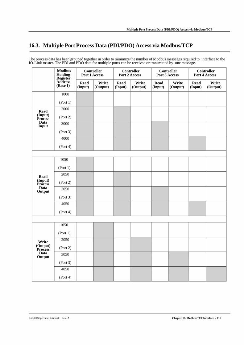
AY1020 Operators Manual: Rev. A Chapter 16. Modbus/TCP Interface - 131
Multiple Port Process Data (PDI/PDO) Access via Modbus/TCP
16.3. Multiple Port Process Data (PDI/PDO) Access via Modbus/TCP
The process data has been grouped together in order to minimize the number of Modbus messages required to interface to the IO-Link master. The PDI and PDO data for multiple ports can be received or transmitted by one message.
Modbus Holding Register Address (Base 1)
Controller Port 1 Access
Controller Port 2 Access
Controller Port 3 Access
Controller Port 4 Access
Read (Input)
Write (Output)
Read (Input)
Write (Output)
Read (Input)
Write (Output)
Read (Input)
Write (Output)
Read (Input) Process
Data Input
1000
(Port 1)
2000
(Port 2)
3000
(Port 3)
4000
(Port 4)
Read (Input) Process
Data Output
1050
(Port 1)
2050
(Port 2)
3050
(Port 3)
4050
(Port 4)
Write (Output) Process
Data Output
1050
(Port 1)
2050
(Port 2)
3050
(Port 3)
4050
(Port 4)
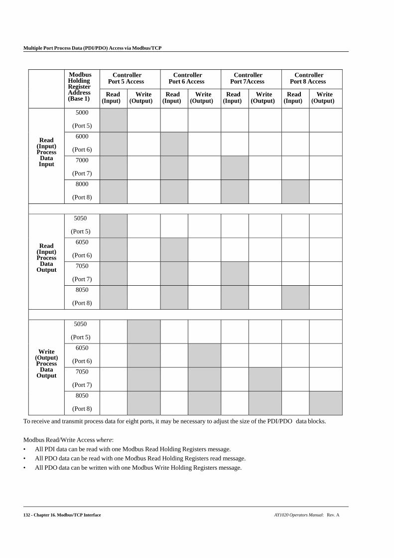
Multiple Port Process Data (PDI/PDO) Access via Modbus/TCP
132 - Chapter 16. Modbus/TCP Interface AY1020 Operators Manual: Rev. A
Modbus
Holding Register Address (Base 1)
Controller Port 5 Access
Controller Port 6 Access
Controller Port 7Access
Controller Port 8 Access
Read (Input)
Write (Output)
Read (Input)
Write (Output)
Read (Input)
Write (Output)
Read (Input)
Write (Output)
Read (Input) Process
Data Input
5000
(Port 5)
6000
(Port 6)
7000
(Port 7)
8000
(Port 8)
Read (Input) Process
Data Output
5050
(Port 5)
6050
(Port 6)
7050
(Port 7)
8050
(Port 8)
Write (Output) Process
Data Output
5050
(Port 5)
6050
(Port 6)
7050
(Port 7)
8050
(Port 8)
To receive and transmit process data for eight ports, it may be necessary to adjust the size of the PDI/PDO data blocks.
Modbus Read/Write Access where:
• All PDI data can be read with one Modbus Read Holding Registers message.
• All PDO data can be read with one Modbus Read Holding Registers read message.
• All PDO data can be written with one Modbus Write Holding Registers message.
Multiple Port Process Data (PDI/PDO) Access via Modbus/TCP
AY1020 Operators Manual: Rev. A Chapter 16. Modbus/TCP Interface - 133
• Controller Read access:
- The PDI data from one or more ports may be read with one message. (i.e.: If addressing port 1, at address 1000, ports one to four may be read in one message.)
- The PDO data from one or more ports may be read with one message. (i.e.: If addressing port 1, at address 1050, ports one to four may be read in one message.)
- Partial PDI and PDO data reads are allowed.
- The length of the Read message can range from 1 to the total, configured PDI or PDO length for all ports starting at the addressed port.
• Controller Write (Output) access:
- Only PDO data may be written.
- The PDO data for one or more ports may be written with one Write Holding Registers message.
- Partial PDO data writes are not allowed.
- The length of the Write message must be equal to the total of the configured PDO lengths for all ports to be written. The one exception is that the data length of the last port to be written must be equal to or greater than the device PDO length for that port.

Multiple Port Process Data (PDI/PDO) Access via Modbus/TCP
134 - Chapter 16. Modbus/TCP Interface AY1020 Operators Manual: Rev. A
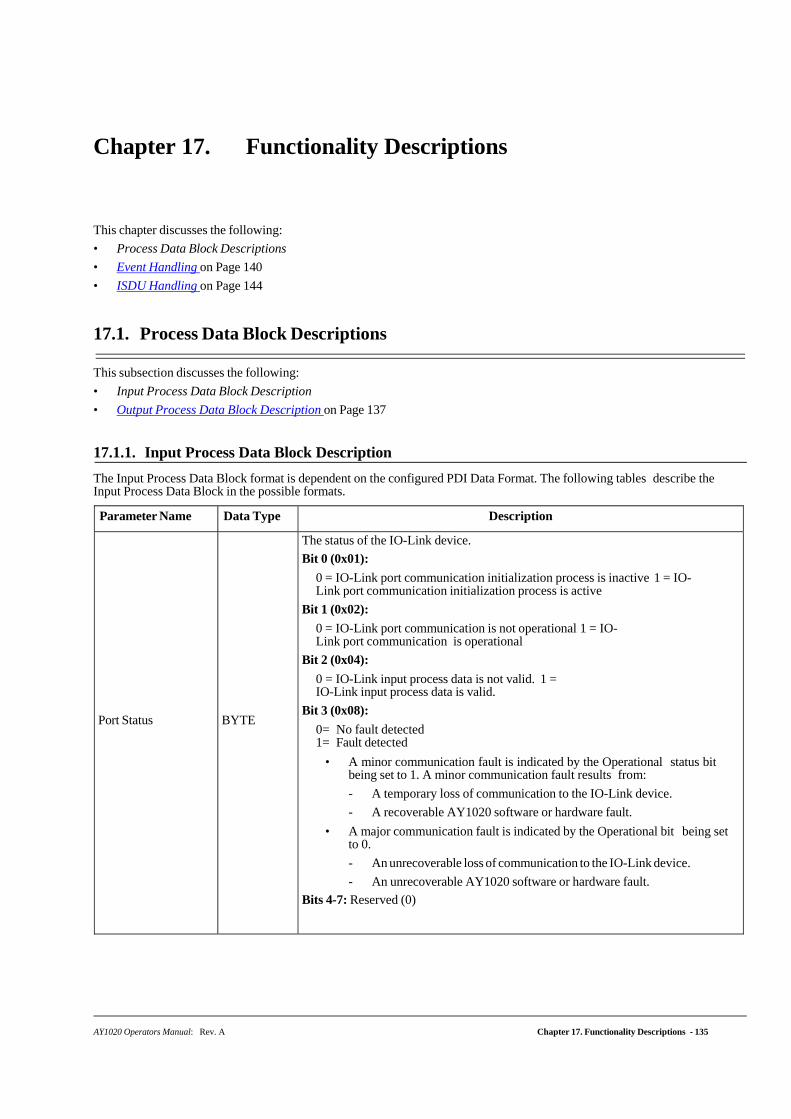
AY1020 Operators Manual: Rev. A Chapter 17. Functionality Descriptions - 135
Chapter 17. Functionality Descriptions
This chapter discusses the following:
• Process Data Block Descriptions
• Event Handling on Page 140
• ISDU Handling on Page 144
17.1. Process Data Block Descriptions
This subsection discusses the following:
• Input Process Data Block Description
• Output Process Data Block Description on Page 137
17.1.1. Input Process Data Block Description
The Input Process Data Block format is dependent on the configured PDI Data Format. The following tables describe the Input Process Data Block in the possible formats.
Parameter Name Data Type Description
Port Status
BYTE
The status of the IO-Link device.
Bit 0 (0x01):
0 = IO-Link port communication initialization process is inactive 1 = IO-Link port communication initialization process is active
Bit 1 (0x02):
0 = IO-Link port communication is not operational 1 = IO-Link port communication is operational
Bit 2 (0x04):
0 = IO-Link input process data is not valid. 1 = IO-Link input process data is valid.
Bit 3 (0x08):
0= No fault detected 1= Fault detected
• A minor communication fault is indicated by the Operational status bit being set to 1. A minor communication fault results from:
- A temporary loss of communication to the IO-Link device.
- A recoverable AY1020 software or hardware fault.
• A major communication fault is indicated by the Operational bit being set to 0.
- An unrecoverable loss of communication to the IO-Link device.
- An unrecoverable AY1020 software or hardware fault.
Bits 4-7: Reserved (0)
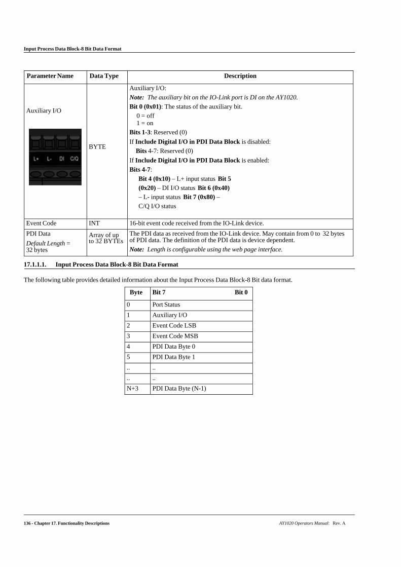
136 - Chapter 17. Functionality Descriptions AY1020 Operators Manual: Rev. A
Input Process Data Block-8 Bit Data Format
Parameter Name Data Type Description
Auxiliary I/O
BYTE
Auxiliary I/O:
Note: The auxiliary bit on the IO-Link port is DI on the AY1020.
Bit 0 (0x01): The status of the auxiliary bit.
0 = off 1 = on
Bits 1-3: Reserved (0)
If Include Digital I/O in PDI Data Block is disabled:
Bits 4-7: Reserved (0)
If Include Digital I/O in PDI Data Block is enabled:
Bits 4-7:
Bit 4 (0x10) – L+ input status Bit 5
(0x20) – DI I/O status Bit 6 (0x40) – L- input status Bit 7 (0x80) –
C/Q I/O status
Event Code INT 16-bit event code received from the IO-Link device.
PDI Data
Default Length = 32 bytes
Array of up to 32 BYTEs
The PDI data as received from the IO-Link device. May contain from 0 to 32 bytes of PDI data. The definition of the PDI data is device dependent.
Note: Length is configurable using the web page interface.
17.1.1.1. Input Process Data Block-8 Bit Data Format
The following table provides detailed information about the Input Process Data Block-8 Bit data format.
Byte Bit 7 Bit 0
0 Port Status
1 Auxiliary I/O
2 Event Code LSB
3 Event Code MSB
4 PDI Data Byte 0
5 PDI Data Byte 1
.. ..
.. ..
N+3 PDI Data Byte (N-1)
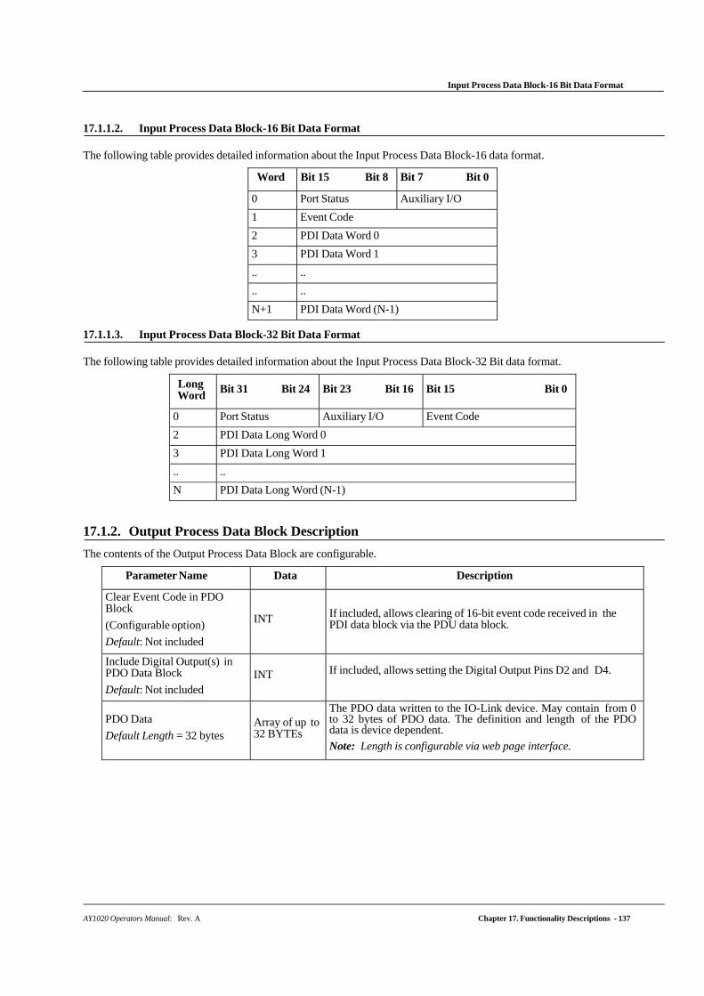
AY1020 Operators Manual: Rev. A Chapter 17. Functionality Descriptions - 137
Input Process Data Block-16 Bit Data Format
17.1.1.2. Input Process Data Block-16 Bit Data Format
The following table provides detailed information about the Input Process Data Block-16 data format.
Word Bit 15 Bit 8 Bit 7 Bit 0
0 Port Status Auxiliary I/O
1 Event Code
2 PDI Data Word 0
3 PDI Data Word 1
.. ..
.. ..
N+1 PDI Data Word (N-1)
17.1.1.3. Input Process Data Block-32 Bit Data Format
The following table provides detailed information about the Input Process Data Block-32 Bit data format.
Long Word
Bit 31 Bit 24 Bit 23 Bit 16 Bit 15 Bit 0
0 Port Status Auxiliary I/O Event Code
2 PDI Data Long Word 0
3 PDI Data Long Word 1
.. ..
N PDI Data Long Word (N-1)
17.1.2. Output Process Data Block Description
The contents of the Output Process Data Block are configurable.
Parameter Name Data Description
Clear Event Code in PDO Block
(Configurable option)
Default: Not included
INT
If included, allows clearing of 16-bit event code received in the PDI data block via the PDU data block.
Include Digital Output(s) in PDO Data Block
Default: Not included
INT If included, allows setting the Digital Output Pins D2 and D4.
PDO Data
Default Length = 32 bytes
Array of up to 32 BYTEs
The PDO data written to the IO-Link device. May contain from 0 to 32 bytes of PDO data. The definition and length of the PDO data is device dependent.
Note: Length is configurable via web page interface.
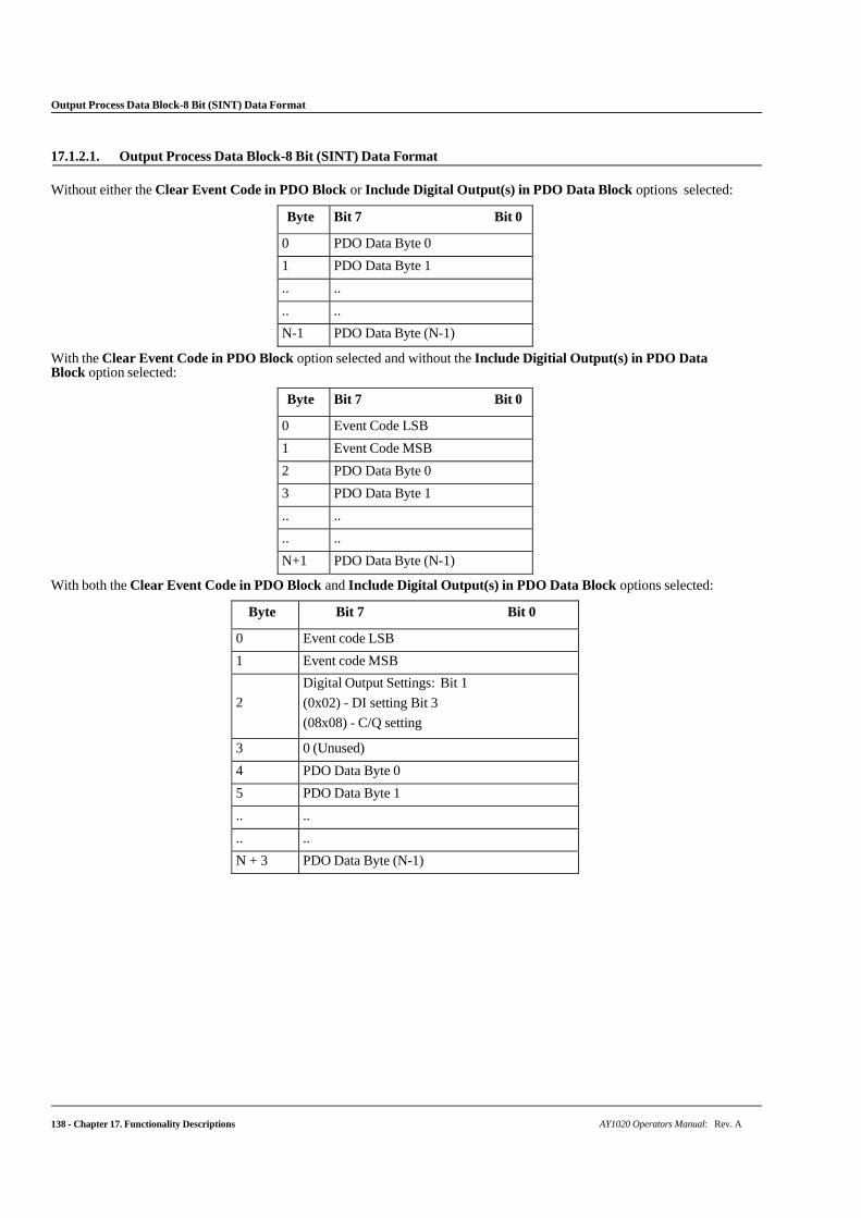
138 - Chapter 17. Functionality Descriptions AY1020 Operators Manual: Rev. A
Output Process Data Block-8 Bit (SINT) Data Format
17.1.2.1. Output Process Data Block-8 Bit (SINT) Data Format
Without either the Clear Event Code in PDO Block or Include Digital Output(s) in PDO Data Block options selected:
Byte Bit 7 Bit 0
0 PDO Data Byte 0
1 PDO Data Byte 1
.. ..
.. ..
N-1 PDO Data Byte (N-1)
With the Clear Event Code in PDO Block option selected and without the Include Digitial Output(s) in PDO Data Block option selected:
Byte Bit 7 Bit 0
0 Event Code LSB
1 Event Code MSB
2 PDO Data Byte 0
3 PDO Data Byte 1
.. ..
.. ..
N+1 PDO Data Byte (N-1)
With both the Clear Event Code in PDO Block and Include Digital Output(s) in PDO Data Block options selected:
Byte Bit 7 Bit 0
0 Event code LSB
1 Event code MSB
2
Digital Output Settings: Bit 1
(0x02) - DI setting Bit 3
(08x08) - C/Q setting
3 0 (Unused)
4 PDO Data Byte 0
5 PDO Data Byte 1
.. ..
.. ..
N + 3 PDO Data Byte (N-1)
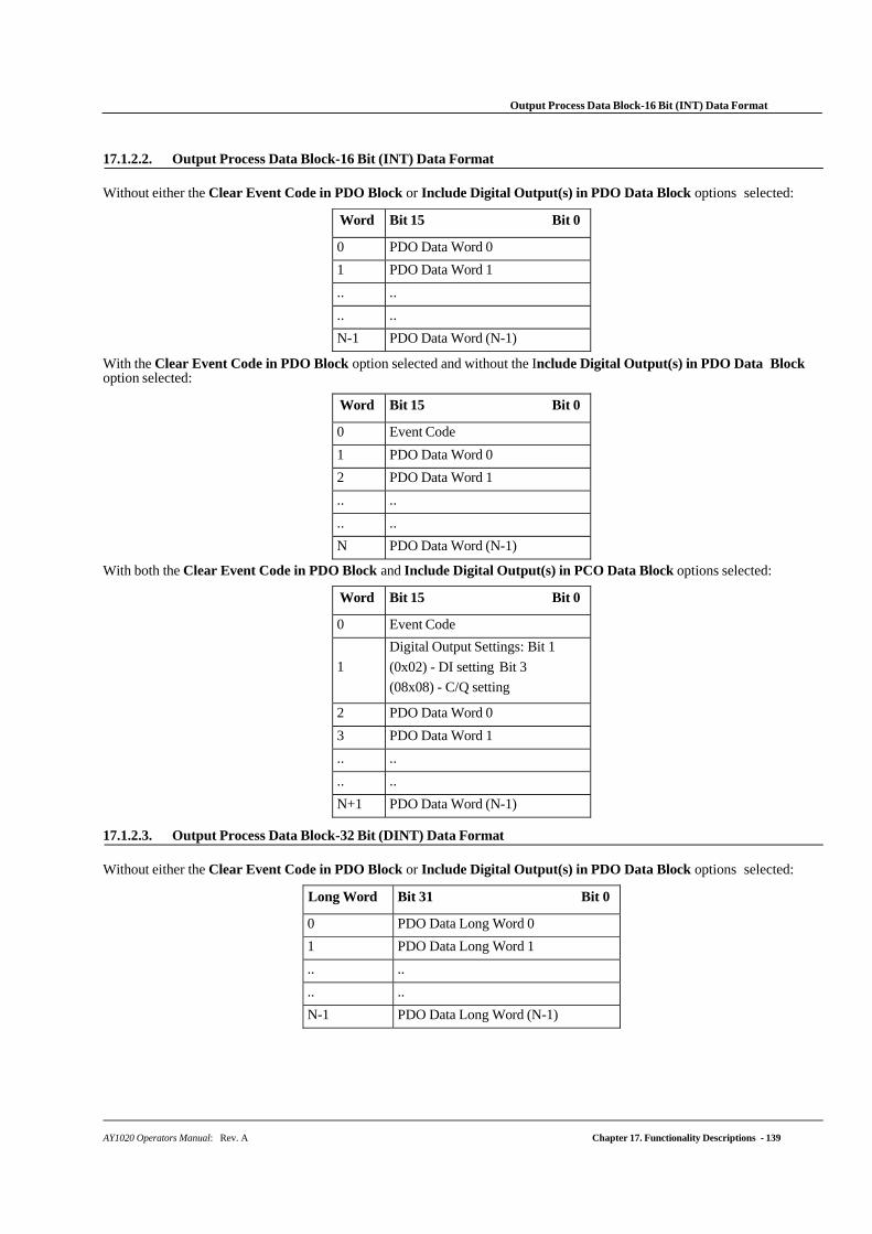
AY1020 Operators Manual: Rev. A Chapter 17. Functionality Descriptions - 139
Output Process Data Block-16 Bit (INT) Data Format
17.1.2.2. Output Process Data Block-16 Bit (INT) Data Format
Without either the Clear Event Code in PDO Block or Include Digital Output(s) in PDO Data Block options selected:
Word Bit 15 Bit 0
0 PDO Data Word 0
1 PDO Data Word 1
.. ..
.. ..
N-1 PDO Data Word (N-1)
With the Clear Event Code in PDO Block option selected and without the Include Digital Output(s) in PDO Data Block option selected:
Word Bit 15 Bit 0
0 Event Code
1 PDO Data Word 0
2 PDO Data Word 1
.. ..
.. ..
N PDO Data Word (N-1)
With both the Clear Event Code in PDO Block and Include Digital Output(s) in PCO Data Block options selected:
Word Bit 15 Bit 0
0 Event Code
1
Digital Output Settings: Bit 1
(0x02) - DI setting Bit 3
(08x08) - C/Q setting
2 PDO Data Word 0
3 PDO Data Word 1
.. ..
.. ..
N+1 PDO Data Word (N-1)
17.1.2.3. Output Process Data Block-32 Bit (DINT) Data Format
Without either the Clear Event Code in PDO Block or Include Digital Output(s) in PDO Data Block options selected:
Long Word Bit 31 Bit 0
0 PDO Data Long Word 0
1 PDO Data Long Word 1
.. ..
.. ..
N-1 PDO Data Long Word (N-1)
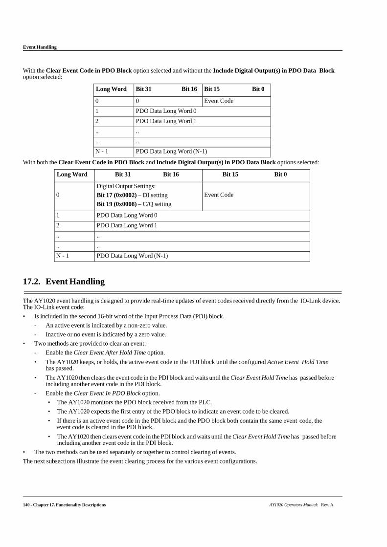
Event Handling
140 - Chapter 17. Functionality Descriptions AY1020 Operators Manual: Rev. A
With the Clear Event Code in PDO Block option selected and without the Include Digital Output(s) in PDO Data Block option selected:
Long Word Bit 31 Bit 16 Bit 15 Bit 0
0 0 Event Code
1 PDO Data Long Word 0
2 PDO Data Long Word 1
.. ..
.. ..
N - 1 PDO Data Long Word (N-1)
With both the Clear Event Code in PDO Block and Include Digital Output(s) in PDO Data Block options selected:
Long Word Bit 31 Bit 16 Bit 15 Bit 0
0
Digital Output Settings:
Bit 17 (0x0002) – DI setting
Bit 19 (0x0008) – C/Q setting
Event Code
1 PDO Data Long Word 0
2 PDO Data Long Word 1
.. ..
.. ..
N - 1 PDO Data Long Word (N-1)
17.2. Event Handling
The AY1020 event handling is designed to provide real-time updates of event codes received directly from the IO-Link device. The IO-Link event code:
• Is included in the second 16-bit word of the Input Process Data (PDI) block.
- An active event is indicated by a non-zero value.
- Inactive or no event is indicated by a zero value.
• Two methods are provided to clear an event:
- Enable the Clear Event After Hold Time option.
• The AY1020 keeps, or holds, the active event code in the PDI block until the configured Active Event Hold Time has passed.
• The AY1020 then clears the event code in the PDI block and waits until the Clear Event Hold Time has passed before including another event code in the PDI block.
- Enable the Clear Event In PDO Block option.
• The AY1020 monitors the PDO block received from the PLC.
• The AY1020 expects the first entry of the PDO block to indicate an event code to be cleared.
• If there is an active event code in the PDI block and the PDO block both contain the same event code, the event code is cleared in the PDI block.
• The AY1020 then clears event code in the PDI block and waits until the Clear Event Hold Time has passed before including another event code in the PDI block.
• The two methods can be used separately or together to control clearing of events.
The next subsections illustrate the event clearing process for the various event configurations.
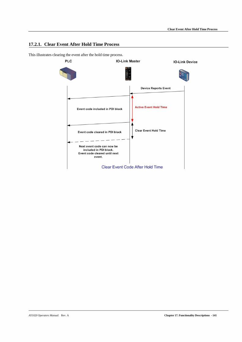
Clear Event After Hold Time Process
AY1020 Operators Manual: Rev. A Chapter 17. Functionality Descriptions - 141
17.2.1. Clear Event After Hold Time Process
This illustrates clearing the event after the hold time process.
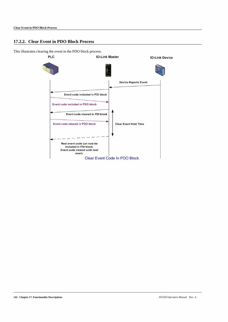
Clear Event in PDO Block Process
142 - Chapter 17. Functionality Descriptions AY1020 Operators Manual: Rev. A
17.2.2. Clear Event in PDO Block Process
This illustrates clearing the event in the PDO block process.
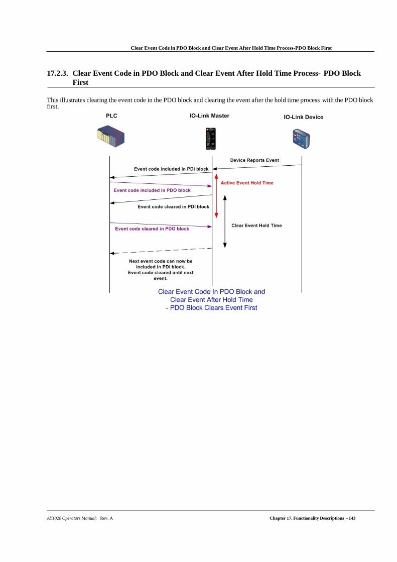
Clear Event Code in PDO Block and Clear Event After Hold Time Process-PDO Block First
AY1020 Operators Manual: Rev. A Chapter 17. Functionality Descriptions - 143
17.2.3. Clear Event Code in PDO Block and Clear Event After Hold Time Process- PDO Block First
This illustrates clearing the event code in the PDO block and clearing the event after the hold time process with the PDO block first.
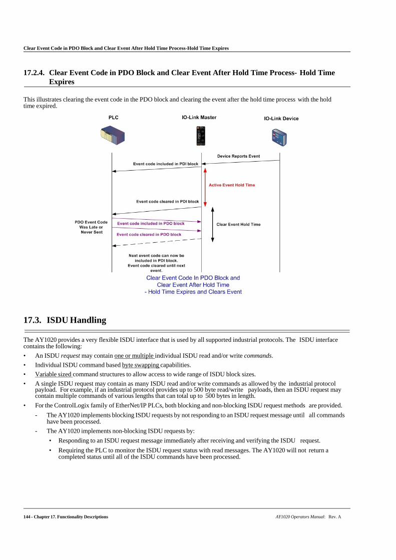
144 - Chapter 17. Functionality Descriptions AY1020 Operators Manual: Rev. A
Clear Event Code in PDO Block and Clear Event After Hold Time Process-Hold Time Expires
17.2.4. Clear Event Code in PDO Block and Clear Event After Hold Time Process- Hold Time Expires
This illustrates clearing the event code in the PDO block and clearing the event after the hold time process with the hold time expired.
17.3. ISDU Handling
The AY1020 provides a very flexible ISDU interface that is used by all supported industrial protocols. The ISDU interface contains the following:
• An ISDU request may contain one or multiple individual ISDU read and/or write commands.
• Individual ISDU command based byte swapping capabilities.
• Variable sized command structures to allow access to wide range of ISDU block sizes.
• A single ISDU request may contain as many ISDU read and/or write commands as allowed by the industrial protocol payload. For example, if an industrial protocol provides up to 500 byte read/write payloads, then an ISDU request may contain multiple commands of various lengths that can total up to 500 bytes in length.
• For the ControlLogix family of EtherNet/IP PLCs, both blocking and non-blocking ISDU request methods are provided.
- The AY1020 implements blocking ISDU requests by not responding to an ISDU request message until all commands have been processed.
- The AY1020 implements non-blocking ISDU requests by:
• Responding to an ISDU request message immediately after receiving and verifying the ISDU request.
• Requiring the PLC to monitor the ISDU request status with read messages. The AY1020 will not return a completed status until all of the ISDU commands have been processed.
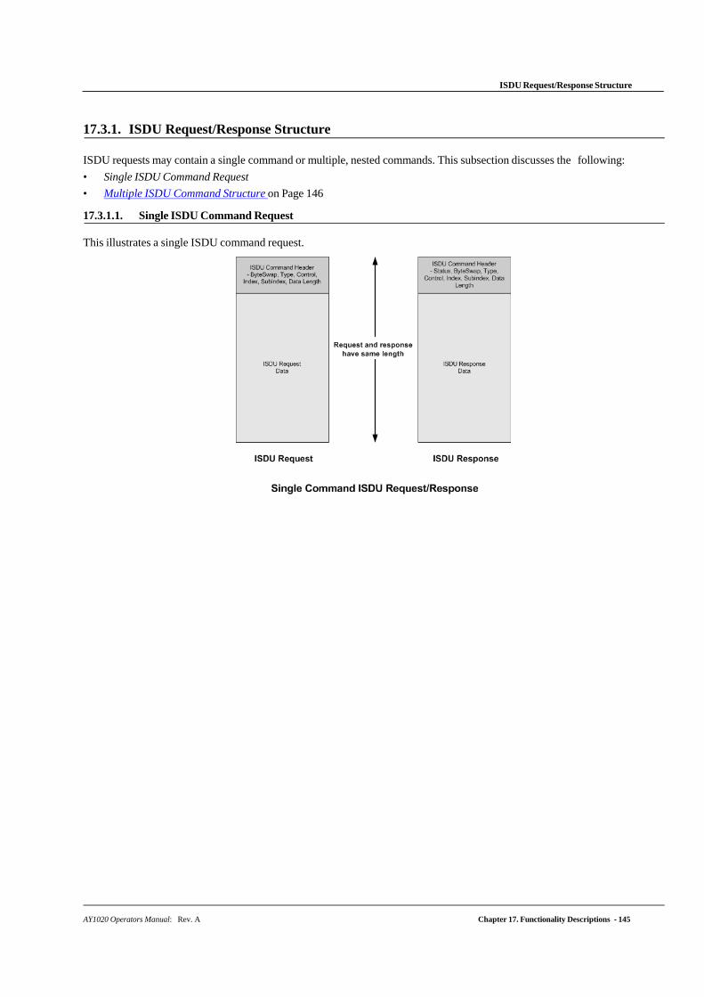
AY1020 Operators Manual: Rev. A Chapter 17. Functionality Descriptions - 145
ISDU Request/Response Structure
17.3.1. ISDU Request/Response Structure
ISDU requests may contain a single command or multiple, nested commands. This subsection discusses the following:
• Single ISDU Command Request
• Multiple ISDU Command Structure on Page 146
17.3.1.1. Single ISDU Command Request
This illustrates a single ISDU command request.
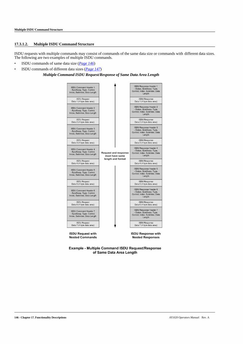
146 - Chapter 17. Functionality Descriptions AY1020 Operators Manual: Rev. A
Multiple ISDU Command Structure
17.3.1.2. Multiple ISDU Command Structure
ISDU requests with multiple commands may consist of commands of the same data size or commands with different data sizes. The following are two examples of multiple ISDU commands.
• ISDU commands of same data size (Page 146)
• ISDU commands of different data sizes (Page 147)
Multiple Command ISDU Request/Response of Same Data Area Length
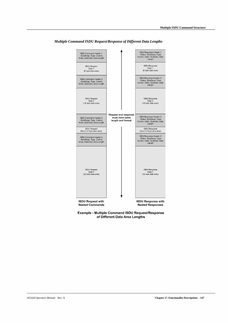
AY1020 Operators Manual: Rev. A Chapter 17. Functionality Descriptions - 147
Multiple ISDU Command Structure
Multiple Command ISDU Request/Response of Different Data Lengths

148 - Chapter 17. Functionality Descriptions AY1020 Operators Manual: Rev. A
ISDU Request Message Format-From PLC to AY1020
17.3.2. ISDU Request Message Format-From PLC to AY1020
Write and read ISDU commands have the same message data format. Each ISDU request message is comprised of one or more commands. The command(s) can consist of either a series of nested commands or a single read command.
Note: A list of nested ISDU commands is terminated with either a control field of 0, (single/last operation), or the end of the message data.
17.3.2.1. Standard ISDU Request Command Format
This table displays a standard ISDU request command format with ControlLogix PLCs.
Name Data Type Parameter Descriptions
Byte Swapping
USINT
Bits 0-3:
0= No byte swapping. 1= 16-bit (INT) byte swapping of ISDU data. 2= 32-bit (DINT) byte swapping of ISDU data.
Bits 4-7:
Set to zero. Unused.
RdWrControlType
USINT
Provides the control and type of ISDU command.
Bits 0-3, Type Field:
0 = NOP (No operation) 1 = Read operation 2 = Write operation 3 = Read/Write “OR” 4 = Read/Write “AND”
Bits 4-7, Control Field:
0 = Single/Last Operation (length can vary from to 1 to 232) 1 = Nested batch command – fixed 4 byte data area 2 = Nested batch command – fixed 8 byte data area 3 = Nested batch command – fixed 16 byte data area 4 = Nested batch command – fixed 32 byte data area 5 = Nested batch command – fixed 64 byte data area 6 = Nested batch command – fixed 128 byte data area 7 = Nested batch command – fixed 232 byte data area
Index UINT The parameter address of the data object in the IO-Link device.
Subindex UINT The data element address of a structured parameter of the data object in the IO-Link device.
Datalength
UINT
Length of data to read or write.
For nested batch commands, the data length can vary from 1 to the fixed data area size.
Data
Array of USINTs, UINTs, or UDINTs.
Size of array is determined by the Control field in RdWrControlType.
Note: Data is valid only for write commands.
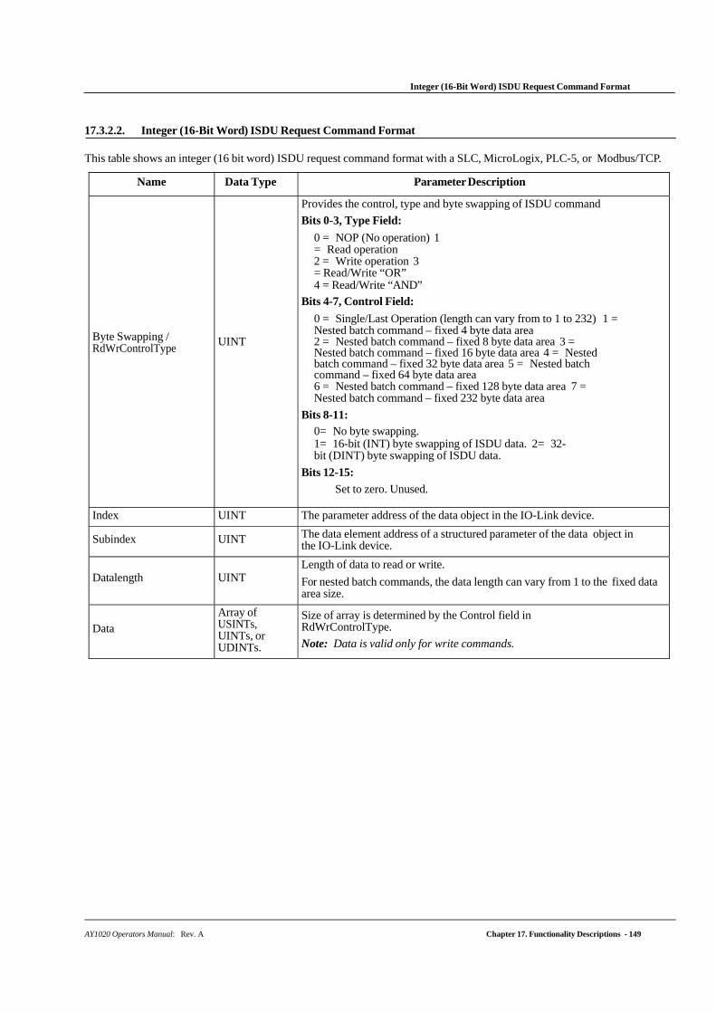
AY1020 Operators Manual: Rev. A Chapter 17. Functionality Descriptions - 149
Integer (16-Bit Word) ISDU Request Command Format
17.3.2.2. Integer (16-Bit Word) ISDU Request Command Format
This table shows an integer (16 bit word) ISDU request command format with a SLC, MicroLogix, PLC-5, or Modbus/TCP.
Name Data Type Parameter Description
Byte Swapping / RdWrControlType
UINT
Provides the control, type and byte swapping of ISDU command
Bits 0-3, Type Field:
0 = NOP (No operation) 1 = Read operation 2 = Write operation 3 = Read/Write “OR” 4 = Read/Write “AND”
Bits 4-7, Control Field:
0 = Single/Last Operation (length can vary from to 1 to 232) 1 = Nested batch command – fixed 4 byte data area 2 = Nested batch command – fixed 8 byte data area 3 = Nested batch command – fixed 16 byte data area 4 = Nested batch command – fixed 32 byte data area 5 = Nested batch command – fixed 64 byte data area 6 = Nested batch command – fixed 128 byte data area 7 = Nested batch command – fixed 232 byte data area
Bits 8-11:
0= No byte swapping. 1= 16-bit (INT) byte swapping of ISDU data. 2= 32-bit (DINT) byte swapping of ISDU data.
Bits 12-15:
Set to zero. Unused.
Index UINT The parameter address of the data object in the IO-Link device.
Subindex UINT The data element address of a structured parameter of the data object in the IO-Link device.
Datalength
UINT
Length of data to read or write.
For nested batch commands, the data length can vary from 1 to the fixed data area size.
Data
Array of USINTs, UINTs, or UDINTs.
Size of array is determined by the Control field in RdWrControlType.
Note: Data is valid only for write commands.
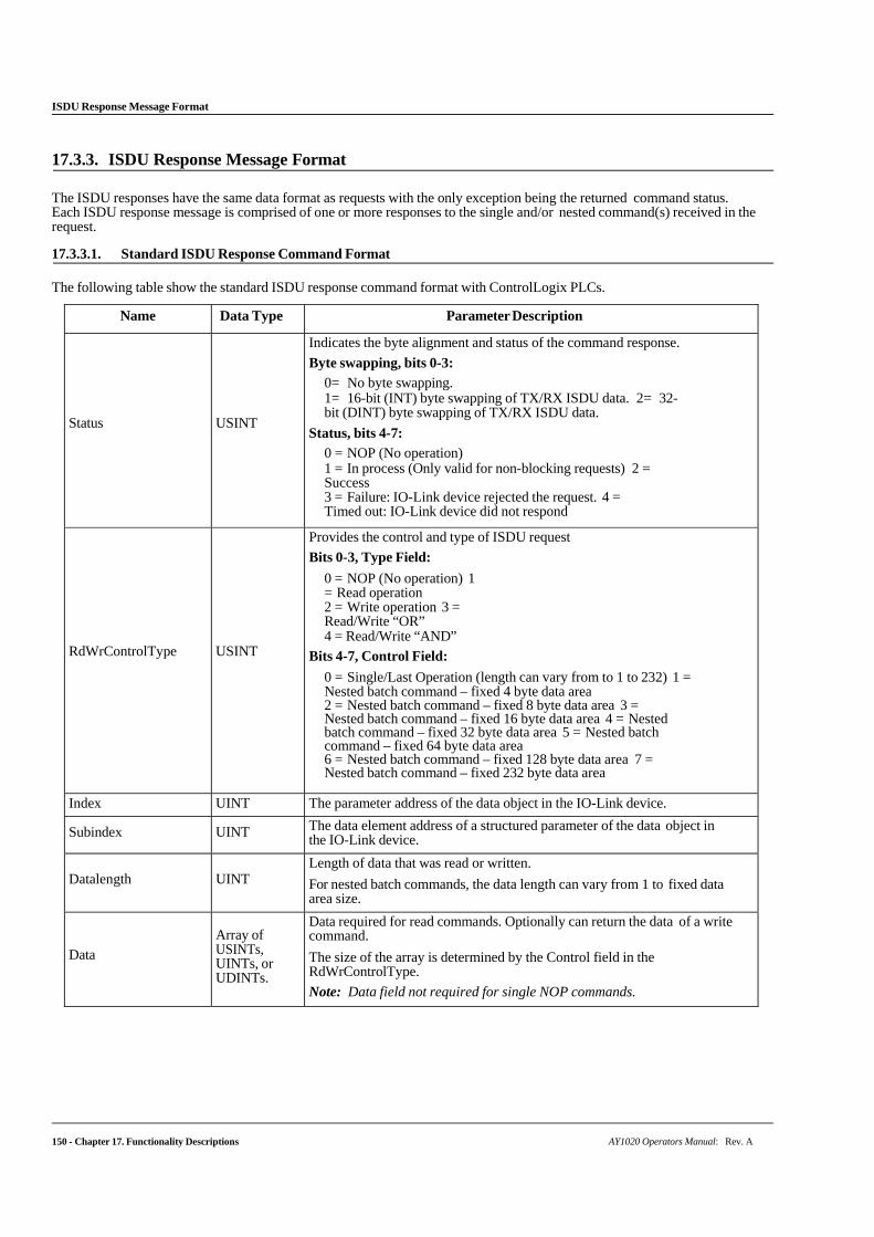
ISDU Response Message Format
150 - Chapter 17. Functionality Descriptions AY1020 Operators Manual: Rev. A
17.3.3. ISDU Response Message Format
The ISDU responses have the same data format as requests with the only exception being the returned command status. Each ISDU response message is comprised of one or more responses to the single and/or nested command(s) received in the request.
17.3.3.1. Standard ISDU Response Command Format
The following table show the standard ISDU response command format with ControlLogix PLCs.
Name Data Type Parameter Description
Status
USINT
Indicates the byte alignment and status of the command response.
Byte swapping, bits 0-3:
0= No byte swapping. 1= 16-bit (INT) byte swapping of TX/RX ISDU data. 2= 32-bit (DINT) byte swapping of TX/RX ISDU data.
Status, bits 4-7:
0 = NOP (No operation) 1 = In process (Only valid for non-blocking requests) 2 = Success 3 = Failure: IO-Link device rejected the request. 4 = Timed out: IO-Link device did not respond
RdWrControlType
USINT
Provides the control and type of ISDU request
Bits 0-3, Type Field:
0 = NOP (No operation) 1 = Read operation 2 = Write operation 3 = Read/Write “OR” 4 = Read/Write “AND”
Bits 4-7, Control Field:
0 = Single/Last Operation (length can vary from to 1 to 232) 1 = Nested batch command – fixed 4 byte data area 2 = Nested batch command – fixed 8 byte data area 3 = Nested batch command – fixed 16 byte data area 4 = Nested batch command – fixed 32 byte data area 5 = Nested batch command – fixed 64 byte data area 6 = Nested batch command – fixed 128 byte data area 7 = Nested batch command – fixed 232 byte data area
Index UINT The parameter address of the data object in the IO-Link device.
Subindex UINT The data element address of a structured parameter of the data object in the IO-Link device.
Datalength
UINT
Length of data that was read or written.
For nested batch commands, the data length can vary from 1 to fixed data area size.
Data
Array of USINTs, UINTs, or UDINTs.
Data required for read commands. Optionally can return the data of a write command.
The size of the array is determined by the Control field in the RdWrControlType.
Note: Data field not required for single NOP commands.
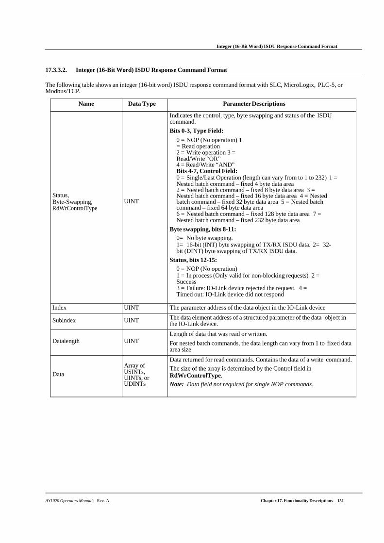
Integer (16-Bit Word) ISDU Response Command Format
AY1020 Operators Manual: Rev. A Chapter 17. Functionality Descriptions - 151
17.3.3.2. Integer (16-Bit Word) ISDU Response Command Format
The following table shows an integer (16-bit word) ISDU response command format with SLC, MicroLogix, PLC-5, or Modbus/TCP.
Name Data Type Parameter Descriptions
Status, Byte-Swapping, RdWrControlType
UINT
Indicates the control, type, byte swapping and status of the ISDU command.
Bits 0-3, Type Field:
0 = NOP (No operation) 1 = Read operation 2 = Write operation 3 = Read/Write “OR” 4 = Read/Write “AND” Bits 4-7, Control Field: 0 = Single/Last Operation (length can vary from to 1 to 232) 1 = Nested batch command – fixed 4 byte data area 2 = Nested batch command – fixed 8 byte data area 3 = Nested batch command – fixed 16 byte data area 4 = Nested batch command – fixed 32 byte data area 5 = Nested batch command – fixed 64 byte data area 6 = Nested batch command – fixed 128 byte data area 7 = Nested batch command – fixed 232 byte data area
Byte swapping, bits 8-11: 0= No byte swapping. 1= 16-bit (INT) byte swapping of TX/RX ISDU data. 2= 32-bit (DINT) byte swapping of TX/RX ISDU data.
Status, bits 12-15:
0 = NOP (No operation) 1 = In process (Only valid for non-blocking requests) 2 = Success 3 = Failure: IO-Link device rejected the request. 4 = Timed out: IO-Link device did not respond
Index UINT The parameter address of the data object in the IO-Link device
Subindex UINT The data element address of a structured parameter of the data object in the IO-Link device.
Datalength
UINT
Length of data that was read or written.
For nested batch commands, the data length can vary from 1 to fixed data area size.
Data
Array of USINTs, UINTs, or UDINTs
Data returned for read commands. Contains the data of a write command.
The size of the array is determined by the Control field in RdWrControlType.
Note: Data field not required for single NOP commands.
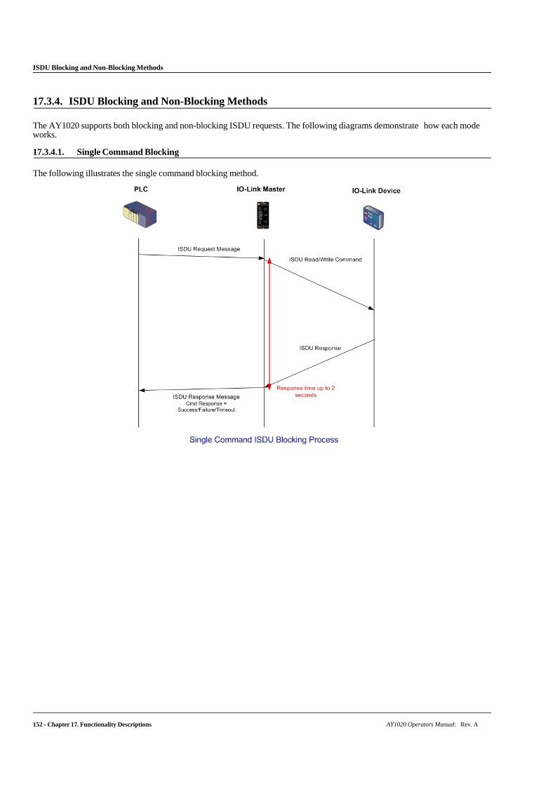
ISDU Blocking and Non-Blocking Methods
152 - Chapter 17. Functionality Descriptions AY1020 Operators Manual: Rev. A
17.3.4. ISDU Blocking and Non-Blocking Methods
The AY1020 supports both blocking and non-blocking ISDU requests. The following diagrams demonstrate how each mode works.
17.3.4.1. Single Command Blocking
The following illustrates the single command blocking method.
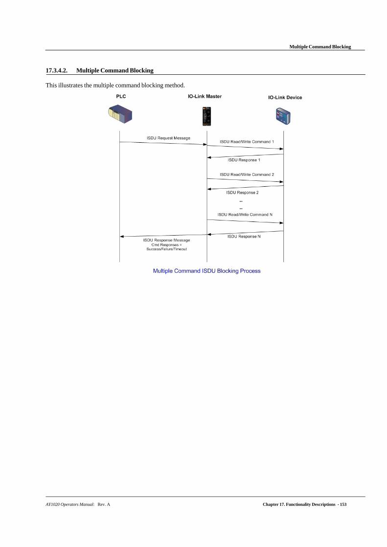
Multiple Command Blocking
AY1020 Operators Manual: Rev. A Chapter 17. Functionality Descriptions - 153
17.3.4.2. Multiple Command Blocking
This illustrates the multiple command blocking method.
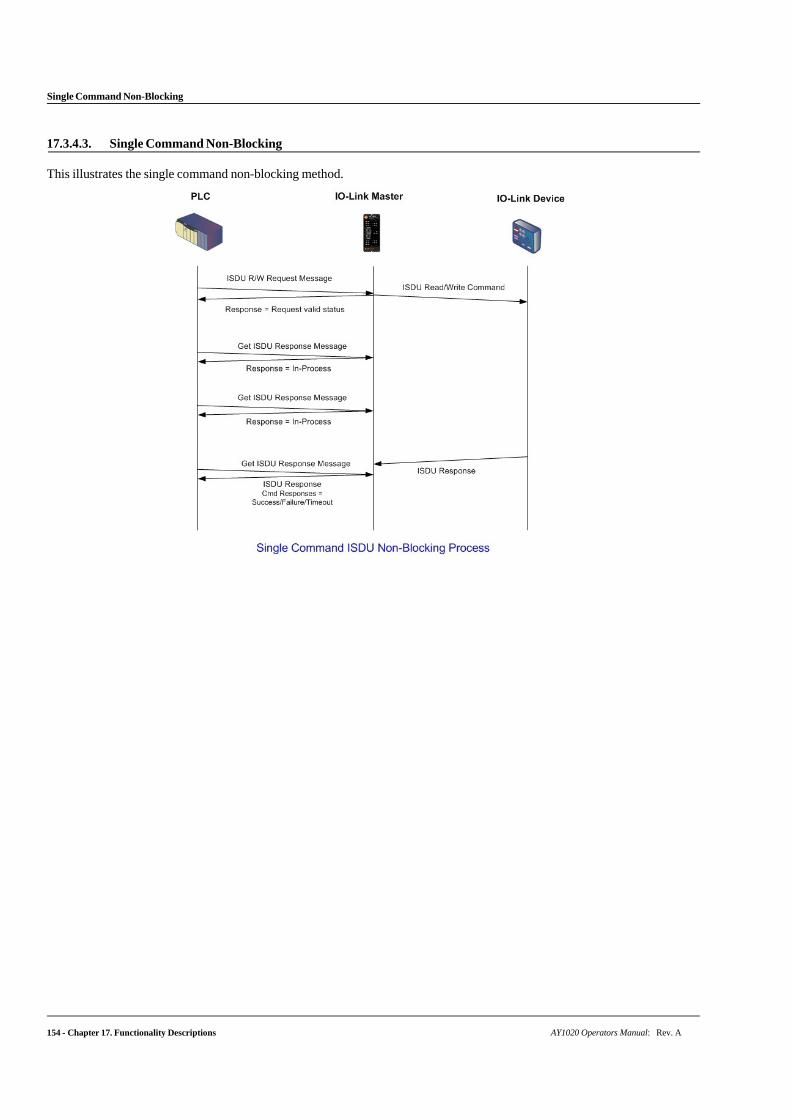
154 - Chapter 17. Functionality Descriptions AY1020 Operators Manual: Rev. A
Single Command Non-Blocking
17.3.4.3. Single Command Non-Blocking
This illustrates the single command non-blocking method.
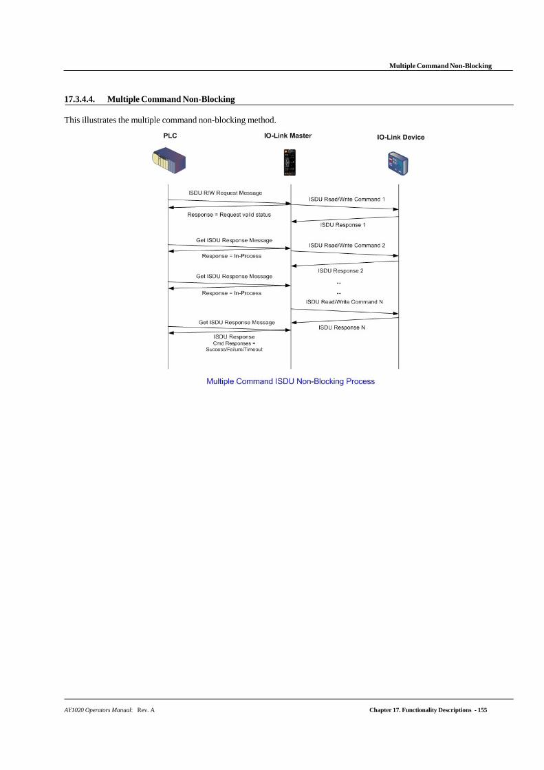
AY1020 Operators Manual: Rev. A Chapter 17. Functionality Descriptions - 155
Multiple Command Non-Blocking
17.3.4.4. Multiple Command Non-Blocking
This illustrates the multiple command non-blocking method.

156 - Chapter 17. Functionality Descriptions AY1020 Operators Manual: Rev. A
Multiple Command Non-Blocking