operating instructions for el6900 -...
TRANSCRIPT
Operating Instructions for
EL6900
TwinSAFE Logic Terminal
2.2.02017-05-10
Version:Date:


Table of contents
EL6900 3Version: 2.2.0
Table of contents1 Foreword .................................................................................................................................................... 5
1.1 Notes on the documentation........................................................................................................... 51.2 Safety instructions .......................................................................................................................... 6
1.2.1 Delivery state ..................................................................................................................... 61.2.2 Operator's obligation to exercise diligence ........................................................................ 61.2.3 Description of safety symbols ............................................................................................ 7
1.3 Documentation issue status............................................................................................................ 8
2 System description ................................................................................................................................... 92.1 The Beckhoff Bus Terminal system ................................................................................................ 9
2.1.1 Bus Coupler ..................................................................................................................... 102.1.2 Bus Terminals .................................................................................................................. 112.1.3 E-bus................................................................................................................................ 112.1.4 Power contacts................................................................................................................. 11
2.2 TwinSAFE..................................................................................................................................... 122.2.1 The I/O construction kit is extended safely ...................................................................... 122.2.2 Safety concept ................................................................................................................. 122.2.3 EL1904, EL2904 - Bus Terminals with 4 fail-safe inputs or outputs ................................ 132.2.4 EL6900 - TwinSAFE logic terminal .................................................................................. 132.2.5 The fail-safe principle (Fail Stop) ..................................................................................... 13
3 Product description................................................................................................................................. 143.1 EL6900 - TwinSAFE logic terminal ............................................................................................... 143.2 Intended use ................................................................................................................................. 143.3 Technical data .............................................................................................................................. 163.4 Safety parameters ........................................................................................................................ 173.5 Dimensions ................................................................................................................................... 18
4 Operation.................................................................................................................................................. 194.1 Environmental conditions.............................................................................................................. 194.2 Installation..................................................................................................................................... 19
4.2.1 Safety instructions............................................................................................................ 194.2.2 Transport / storage........................................................................................................... 194.2.3 Mechanical installation..................................................................................................... 194.2.4 Electrical installation......................................................................................................... 234.2.5 TwinSAFE reaction times................................................................................................. 274.2.6 Tested EL1904 devices ................................................................................................... 284.2.7 Tested EL2904 devices ................................................................................................... 28
4.3 Operation in potentially explosive atmospheres (ATEX) .............................................................. 294.3.1 Special conditions ............................................................................................................ 294.3.2 Identification..................................................................................................................... 304.3.3 Date code and serial number........................................................................................... 304.3.4 Further ATEX documentation .......................................................................................... 30
4.4 Configuration of the terminal in TwinCAT ..................................................................................... 304.4.1 Configuration requirements.............................................................................................. 304.4.2 Inserting a Bus Coupler ................................................................................................... 314.4.3 Inserting a Bus Terminal .................................................................................................. 314.4.4 Inserting an EL6900......................................................................................................... 314.4.5 Address settings on TwinSAFE terminals with 1023 possible addresses........................ 324.4.6 Registering the TwinSAFE addresses in the TwinCAT automation software .................. 324.4.7 Creating a TwinSAFE group ............................................................................................ 334.4.8 TwinSAFE group signals.................................................................................................. 35

Table of contents
EL69004 Version: 2.2.0
4.4.9 Append a function block................................................................................................... 364.4.10 EL6900 user and version administration.......................................................................... 414.4.11 Export and import of a TwinSAFE project ........................................................................ 464.4.12 EL6900 info data.............................................................................................................. 474.4.13 Loading the project into the EL6900 ................................................................................ 474.4.14 Communication between TwinCAT controllers ................................................................ 49
4.5 Diagnostics ................................................................................................................................... 534.5.1 Diagnostic LEDs............................................................................................................... 534.5.2 Diagnostic object.............................................................................................................. 544.5.3 Cycle time of the safety project ........................................................................................ 564.5.4 Status LEDs ..................................................................................................................... 56
4.6 Maintenance ................................................................................................................................. 564.7 Service life .................................................................................................................................... 574.8 Decommissioning ......................................................................................................................... 57
5 Appendix .................................................................................................................................................. 585.1 Support and Service ..................................................................................................................... 585.2 Certificates.................................................................................................................................... 59

Foreword
EL6900 5Version: 2.2.0
1 Foreword
1.1 Notes on the documentation
Intended audience
This description is only intended for the use of trained specialists in control and automation engineering whoare familiar with the applicable national standards.
It is essential that the following notes and explanations are followed when installing and commissioningthese components.
The responsible staff must ensure that the application or use of the products described satisfy all therequirements for safety, including all the relevant laws, regulations, guidelines and standards.
Origin of the document
This documentation was originally written in German. All other languages are derived from the Germanoriginal.
Currentness
Please check whether you are using the current and valid version of this document. The current version canbe downloaded from the Beckhoff homepage at http://www.beckhoff.com/english/download/twinsafe.htm.In case of doubt, please contact Technical Support [} 58].
Product features
Only the product features specified in the current user documentation are valid. Further information given onthe product pages of the Beckhoff homepage, in emails or in other publications is not authoritative.
Disclaimer
The documentation has been prepared with care. The products described are subject to cyclical revision. Forthat reason the documentation is not in every case checked for consistency with performance data,standards or other characteristics. We reserve the right to revise and change the documentation at any timeand without prior announcement. No claims for the modification of products that have already been suppliedmay be made on the basis of the data, diagrams and descriptions in this documentation.
Trademarks
Beckhoff®, TwinCAT®, EtherCAT®, Safety over EtherCAT®, TwinSAFE®, XFC® and XTS® are registeredtrademarks of and licensed by Beckhoff Automation GmbH.Other designations used in this publication may be trademarks whose use by third parties for their ownpurposes could violate the rights of the owners.
Patent Pending
The EtherCAT Technology is covered, including but not limited to the following patent applications andpatents: EP1590927, EP1789857, DE102004044764, DE102007017835 with corresponding applications orregistrations in various other countries.
The TwinCAT Technology is covered, including but not limited to the following patent applications andpatents: EP0851348, US6167425 with corresponding applications or registrations in various other countries.

Foreword
EL69006 Version: 2.2.0
EtherCAT® is registered trademark and patented technology, licensed by Beckhoff Automation GmbH,Germany
Copyright
© Beckhoff Automation GmbH & Co. KG, Germany.The reproduction, distribution and utilization of this document as well as the communication of its contents toothers without express authorization are prohibited.Offenders will be held liable for the payment of damages. All rights reserved in the event of the grant of apatent, utility model or design.
Delivery conditions
In addition, the general delivery conditions of the company Beckhoff Automation GmbH & Co. KG apply.
1.2 Safety instructions
1.2.1 Delivery stateAll the components are supplied in particular hardware and software configurations appropriate for theapplication. Modifications to hardware or software configurations other than those described in thedocumentation are not permitted, and nullify the liability of Beckhoff Automation GmbH & Co. KG.
1.2.2 Operator's obligation to exercise diligenceThe operator must ensure that
• the TwinSAFE products are only used as intended (see chapter Product description);• the TwinSAFE products are only operated in sound condition and in working order.• the TwinSAFE products are operated only by suitably qualified and authorized personnel.• the personnel is instructed regularly about relevant occupational safety and environmental protection
aspects, and is familiar with the operating instructions and in particular the safety instructions containedherein.
• the operating instructions are in good condition and complete, and always available for reference at thelocation where the TwinSAFE products are used.
• none of the safety and warning notes attached to the TwinSAFE products are removed, and all notesremain legible.

Foreword
EL6900 7Version: 2.2.0
1.2.3 Description of safety symbolsIn these operating instructions the following symbols are used with an accompanying safety instruction ornote. The safety instructions must be read carefully and followed without fail!
DANGER
Serious risk of injury!Failure to follow the safety instructions associated with this symbol directly endangers thelife and health of persons.
WARNING
Risk of injury!Failure to follow the safety instructions associated with this symbol endangers the life andhealth of persons.
CAUTION
Personal injuries!Failure to follow the safety instructions associated with this symbol can lead to injuries topersons.
Attention
Damage to the environment or devicesFailure to follow the instructions associated with this symbol can lead to damage to the en-vironment or equipment.
Note
Tip or pointerThis symbol indicates information that contributes to better understanding.
Foreword
EL69008 Version: 2.2.0
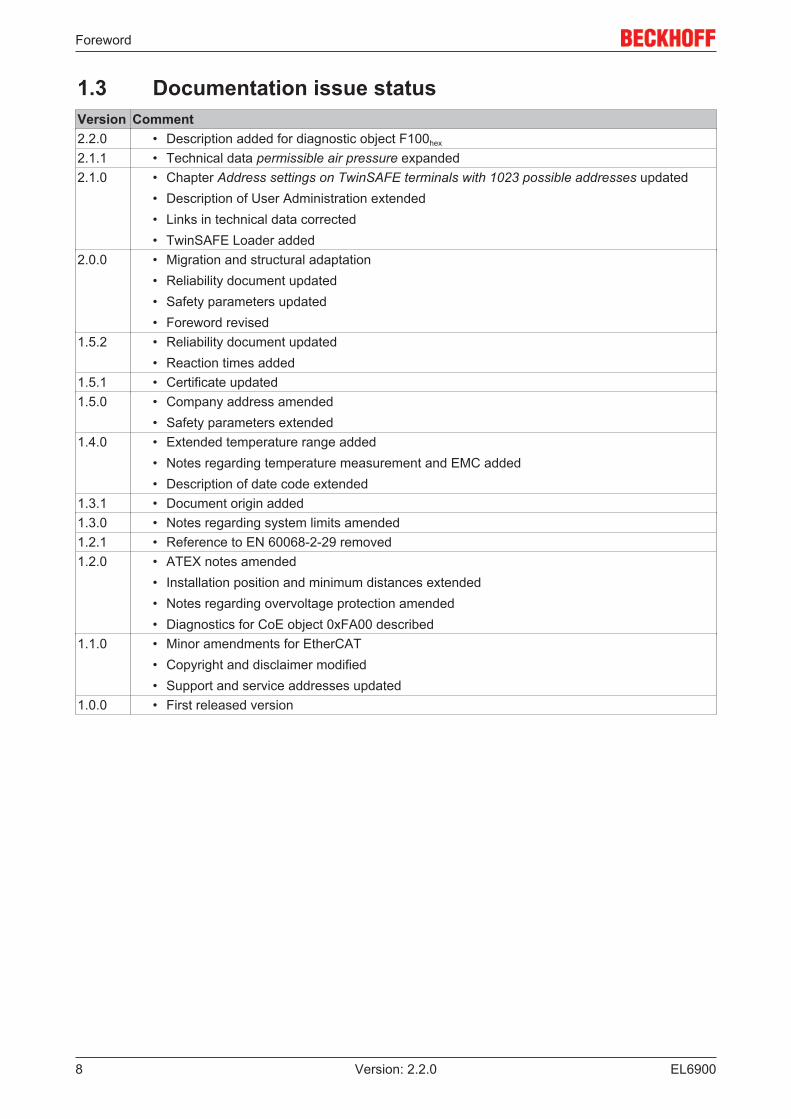
1.3 Documentation issue statusVersion Comment2.2.0 • Description added for diagnostic object F100hex
2.1.1 • Technical data permissible air pressure expanded2.1.0 • Chapter Address settings on TwinSAFE terminals with 1023 possible addresses updated
• Description of User Administration extended• Links in technical data corrected• TwinSAFE Loader added
2.0.0 • Migration and structural adaptation• Reliability document updated• Safety parameters updated• Foreword revised
1.5.2 • Reliability document updated• Reaction times added
1.5.1 • Certificate updated1.5.0 • Company address amended
• Safety parameters extended1.4.0 • Extended temperature range added
• Notes regarding temperature measurement and EMC added• Description of date code extended
1.3.1 • Document origin added1.3.0 • Notes regarding system limits amended1.2.1 • Reference to EN 60068-2-29 removed1.2.0 • ATEX notes amended
• Installation position and minimum distances extended• Notes regarding overvoltage protection amended• Diagnostics for CoE object 0xFA00 described
1.1.0 • Minor amendments for EtherCAT• Copyright and disclaimer modified• Support and service addresses updated
1.0.0 • First released version

System description
EL6900 9Version: 2.2.0
2 System description
2.1 The Beckhoff Bus Terminal systemThe Beckhoff Bus Terminal system is used for decentralized connection of sensors and actuators to acontrol system. The Beckhoff Bus Terminal system components are mainly used in industrial automation andbuilding management applications. In its minimum configuration, a bus station consists of a Bus Coupler or aBus Terminal Controller and Bus Terminals connected to it. The Bus Coupler forms the communicationinterface to the higher-level controller, and the terminals are the interface to sensors and actuators. Thewhole bus station is clipped onto a 35 mm DIN mounting rail (EN 60715). The mechanical cross connectionof the bus station is established via a slot and key system at the Bus Coupler and the Bus Terminals.
The sensors and actuators are connected with the terminals via the screwless (spring-loaded) connectionsystem.
Fig. 1: Slot and key system and screwless (spring-loaded) connection system.
In order to accommodate the wide range of different communication standards encountered in industrialautomation, Beckhoff offers Bus Couplers for a number of common bus systems (e.g. EK1100 forEtherCAT).
System description
EL690010 Version: 2.2.0
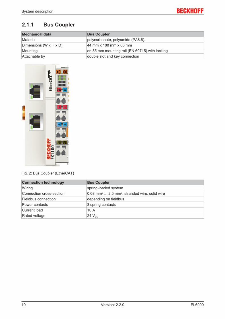
2.1.1 Bus CouplerMechanical data Bus CouplerMaterial polycarbonate, polyamide (PA6.6).Dimensions (W x H x D) 44 mm x 100 mm x 68 mmMounting on 35 mm mounting rail (EN 60715) with lockingAttachable by double slot and key connection
Fig. 2: Bus Coupler (EtherCAT)
Connection technology Bus CouplerWiring spring-loaded systemConnection cross-section 0.08 mm² ... 2.5 mm², stranded wire, solid wireFieldbus connection depending on fieldbusPower contacts 3 spring contactsCurrent load 10 ARated voltage 24 VDC
System description
EL6900 11Version: 2.2.0
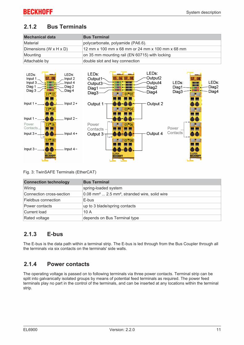
2.1.2 Bus TerminalsMechanical data Bus TerminalMaterial polycarbonate, polyamide (PA6.6).Dimensions (W x H x D) 12 mm x 100 mm x 68 mm or 24 mm x 100 mm x 68 mmMounting on 35 mm mounting rail (EN 60715) with lockingAttachable by double slot and key connection
Fig. 3: TwinSAFE Terminals (EtherCAT)
Connection technology Bus TerminalWiring spring-loaded systemConnection cross-section 0.08 mm² ... 2.5 mm², stranded wire, solid wireFieldbus connection E-busPower contacts up to 3 blade/spring contactsCurrent load 10 ARated voltage depends on Bus Terminal type
2.1.3 E-busThe E-bus is the data path within a terminal strip. The E-bus is led through from the Bus Coupler through allthe terminals via six contacts on the terminals' side walls.
2.1.4 Power contactsThe operating voltage is passed on to following terminals via three power contacts. Terminal strip can besplit into galvanically isolated groups by means of potential feed terminals as required. The power feedterminals play no part in the control of the terminals, and can be inserted at any locations within the terminalstrip.

System description
EL690012 Version: 2.2.0
2.2 TwinSAFE
2.2.1 The I/O construction kit is extended safelyWith the TwinSAFE Terminals, Beckhoff offers the option of simply expanding the proven Bus Terminalsystem, and to transfer the complete cabling for the safety circuit into the already existing fieldbus cable.Safe signals can be mixed with standard signals without restriction. This saves design effort, installation andmaterial. Maintenance is simplified significantly through faster diagnosis and simple replacement of only afew components.
The new ELx9xx series Bus Terminals only include three basic functionalities: digital inputs EL19xx, digitaloutputs EL29xx and a logic unit EL6900. For a large number of applications, all sensors and actuators canbe wired on these Bus Terminals. The required logical link of the inputs and the outputs is handled by theEL6900. For small to medium-sized configurations, the tasks of a fail-safe PLC can thus be handled withinthe Bus Terminal system.
2.2.2 Safety concept
TwinSAFE: Safety and I/O technology in one system• Extension of the familiar Beckhoff I/O system with TwinSAFE terminals• Freely selectable mix of safe and standard signals• Logical link of the I/Os in the EL6900 TwinSAFE logic terminal• Safety-relevant networking of machines via bus systems
TwinSAFE protocol (FSoE)• Transfer of safety-relevant data via any media (“genuine black channel”)• TwinSAFE communication via fieldbus systems such as EtherCAT, Lightbus, PROFIBUS or Ethernet• IEC 61508:2010 SIL 3 compliant
Configuring instead of wiring: the TwinSAFE configurator• Configuration of the TwinSAFE system via the TwinCAT System Manager• System Manager for editing and displaying all bus parameters• Certified function blocks such as emergency stop, operation mode, etc.• Simple handling• Typical function blocks for machine safety• any bus connection with the EL6900 TwinSAFE logic terminal
TwinSAFE logic Bus Terminal EL6900• Link unit between TwinSAFE input and output terminals• Configuration of a simple, flexible, cost-effective, decentralized safety controller• No safety requirements for higher-level control system• TwinSAFE enables networks with up to 65535 TwinSAFE devices• TwinSAFE logic terminal can establish up to 128 connections (TwinSAFE connections).• Several TwinSAFE logic terminals are cascadable in a network• Safety functions such as emergency stop, protective door, etc. are already included• Suitable for applications up to SIL 3 according to IEC 61508:2010 and
DIN EN ISO 13849-1:2006 (Cat 4, PL e).
TwinSAFE digital input (EL1904) and output terminal (EL2904)• All current safety sensors can be connected

System description
EL6900 13Version: 2.2.0
• Operation with a TwinSAFE logic terminal• EL1904 with 4 fail-safe inputs for sensors (24 VDC) with floating contacts• EL2904 with four safe channels for actuators (24 VDC, 0.5 A per channel)• Conforming to IEC 61508:2010 SIL 3 and DIN EN ISO 13849-1:2006 (Cat 4, PL e) requirements.
2.2.3 EL1904, EL2904 - Bus Terminals with 4 fail-safe inputs oroutputs
The EL1904 and EL2904 Bus Terminals enable connection of common safety sensors and actuators. Theyare operated with the EL6900 TwinSAFE logic terminal. The TwinSAFE logic terminal is the link unit betweenthe TwinSAFE input and output terminals. It enables the configuration of a simple, flexible and cost-effectivedecentralized safety control system.
Therefore, there are no safety requirements for the higher-level controller! The typical safety functionsrequired for the automation of machines, such as emergency stop, protective door, two-hand etc., arealready permanently programmed in the EL6900. The user configures the EL6900 terminal according to thesafety requirements of his application.
2.2.4 EL6900 - TwinSAFE logic terminalThe TwinSAFE logic terminal is the link unit between the TwinSAFE input and output terminals. The EL6900meets the requirements of IEC 61508:2010 SIL 3, EN 954 Cat. 4 and DIN EN ISO 13849-1:2006 (Cat 4, PLe).
2.2.5 The fail-safe principle (Fail Stop)The basic rule for a safety system such as TwinSAFE is that failure of a part, a system component or theoverall system must never lead to a dangerous condition. The safe state is always the switched off andwattless state.

Product description
EL690014 Version: 2.2.0
3 Product description
3.1 EL6900 - TwinSAFE logic terminalThe TwinSAFE logic terminal is the link unit between the TwinSAFE input and output terminals.
The EL6900 meets the requirements of IEC 61508:2010 SIL 3, DIN EN ISO 13849-1:2006 (Cat 4, PL e),NRTL, UL508, UL1998 and UL991.
The TwinSAFE terminal has the typical design of an EtherCAT terminal.
Fig. 4: EL6900 - TwinSAFE logic terminal
3.2 Intended use
WARNING
Caution - Risk of injury!TwinSAFE components may only be used for the purposes described below!
WARNING
System limitsThe TÜV SÜD certificate applies to the EL6900, the function blocks available in it, the doc-umentation and the engineering tool. The permitted engineering tool is TwinCAT with the"TwinSAFE Verifier", the TwinSAFE Loader or "CODESYS Safety for EtherCAT SafetyModule". Any deviations from the procedures or tools, particularly externally generated xmlfiles for TwinSAFE import or externally generated automatic project creation procedures,are not covered by the certificate.
The TwinSAFE terminals expand the application range of Beckhoff Bus Terminal system with functions thatenable them to be used for machine safety applications. The TwinSAFE terminals are designed for machinesafety functions and directly associated industrial automation tasks. They are therefore only approved forapplications with a defined fail-safe state. This safe state is the wattless state. Fail-safety according to therelevant standards is required.
Product description
EL6900 15Version: 2.2.0
The TwinSAFE Terminals enable connection of:
• 24 VDC sensors (EL1904) such as emergency off pushbutton switches, pull cord switches, position switches, two-hand switches, safetymats, light curtains, light barriers, laser scanner, etc.
• 24 VDC actuators (EL2904) such as contactors, protection door switches with tumbler, signal lamps, servo drives, etc.
Note
Test pulsesWhen selecting actuators please ensure that the EL2904 test pulses do not lead to actuatorswitching or diagnostic message from the EL2904.
The following TwinSAFE components have been developed for these tasks:
• The EL1904 is an EtherCAT Terminal with 4 digital fail-safe inputs.• The EL2904 is an EtherCAT Terminal with 4 digital fail-safe outputs.• The EL6900 is an EtherCAT Terminal with integrated TwinSAFE logic.
These TwinSAFE components are suitable for operation on the
• Beckhoff EKxxxx series Bus Couplers• Beckhoff CXxxxx series Embedded PCs with E-bus connection
WARNING
Power supply from SELV/PELV power supply unit!The TwinSAFE components must be supplied with 24 VDC by an SELV/PELV power supplyunit with an output voltage limit Umax of 36 VDC. Failure to observe this can result in a loss ofsafety.
CAUTION
Follow the machinery directive!The TwinSAFE components may only be used in machines as defined in the machinery di-rective.
CAUTION
Ensure traceability!The buyer has to ensure the traceability of the device via the serial number.

Product description
EL690016 Version: 2.2.0
3.3 Technical dataProduct designation EL6900Number of inputs 0Number of outputs 0Status display 4 diagnostic LEDsMinimum cycle time approx. 500 µsError reaction time ≤ watchdog timesWatchdog time Min. 2 ms, max. 60000 msInput process image Dynamic according to the TwinSAFE configuration in
the TwinCAT System ManagerOutput process image Dynamic according to the TwinSAFE configuration in
the TwinCAT System ManagerEL6900 supply voltage (PELV) 24 VDC (–15%/+20%)Current consumption via E-bus approx. 188 mAPower dissipation of the terminal typically 1 WDimensions (W x H x D) 12mm x 100mm x 68mmWeight approx. 50 gPermissible ambient temperature (operation) up to SW 04
0°C to +55°C (see notes in section Exampleconfiguration for temperature measurement [} 21])
Permissible ambient temperature (operation) from SW 05 (week 02/2014)
-25°C to +55°C (see notes in section Exampleconfiguration for temperature measurement [} 21])
Permissible ambient temperature (transport/storage) -40°C to +70°CPermissible air humidity 5% to 95%, non-condensingPermissible air pressure (operation/storage/transport)
750 hPa to 1100 hPa(this corresponds to a height of approx. -690 m to2450 m over sea level assuming an internationalstandard atmosphere)
Climate category according to EN 60721-3-3 3K3 (the deviation from 3K3 is possible only with optimalenvironmental conditions and also applies only to thetechnical data which are specified differently in thisdocumentation)
Permissible level of contamination according to EN 60664-1
level of contamination 2(comply with the chapter Maintenance [} 56])
Impermissible operating conditions TwinSAFE terminals must not be used under thefollowing operating conditions:
• under the influence of ionizing radiation (thatexceeds the level of the natural environmentalradiation)
• in corrosive environments• in an environment that leads to unacceptable
soiling of the Bus TerminalVibration/shock resistance conforms to EN 60068-2-6 / EN 60068-2-27EMC immunity/emission conforms to EN 61000-6-2 / EN 61000-6-4Shocks 15 g with pulse duration 11 ms in all three axesProtection class IP20Permitted operating environment In the control cabinet or terminal box, with minimum
protection class IP54 according to IEC 60529Permissible installation position see chapter Installation position and minimum
distances [} 20]Approvals CE, cULus, ATEX, TÜV SÜD

Product description
EL6900 17Version: 2.2.0
3.4 Safety parametersKey figures EL6900Lifetime [a] 20Prooftest Interval [a] not required 1
PFHD 1.03E-09%SIL3 1,03%PFD 8.23E-05%SIL3 8,23%MTTFd highDC highPerformance level PL eCategory 4HFT 1Element classification 2 Type B
1. Special proof tests are not required during the entire service life of the EL6900 EtherCAT terminal.2. Classification according to IEC 61508-2:2010 (see chapters 7.4.4.1.2 and 7.4.4.1.3)
The EL6900 EtherCAT Terminal can be used for safety-related applications within the meaning ofIEC 61508:2010 up to SIL3 and EN ISO 13849-1 up to PL e (Cat4).
For the calculation or estimation of the MTTFd value from the PFHD value, further information can be found inthe TwinSAFE application manual or in ISO 13849-1:2015 Table K.1.

Product description
EL690018 Version: 2.2.0
3.5 Dimensions
Fig. 5: Dimensions of the EL6900
Width: 12 mm (side-by-side installation)Height: 100 mmDepth: 68 mm

Operation
EL6900 19Version: 2.2.0
4 Operation
4.1 Environmental conditionsPlease ensure that the TwinSAFE components are only transported, stored and operated under the specifiedconditions (see technical data)!
WARNING
Risk of injury!The TwinSAFE components must not be used under the following operating conditions.
• under the influence of ionizing radiation (that exceeds the level of the natural environ-mental radiation)
• in corrosive environments• in an environment that leads to unacceptable soiling of the TwinSAFE component
Attention
Electromagnetic compatibilityThe TwinSAFE components comply with the current standards on electromagnetic compat-ibility with regard to spurious radiation and immunity to interference in particular.However, in cases where devices such as mobile phones, radio equipment, transmitters orhigh-frequency systems that exceed the interference emissions limits specified in the stan-dards are operated near TwinSAFE components, the function of the TwinSAFE compo-nents may be impaired.
4.2 Installation
4.2.1 Safety instructionsBefore installing and commissioning the TwinSAFE components please read the safety instructions in theforeword of this documentation.
4.2.2 Transport / storageUse the original packaging in which the components were delivered for transporting and storing theTwinSAFE components.
CAUTION
Note the specified environmental conditionsPlease ensure that the digital TwinSAFE components are only transported and stored un-der the specified environmental conditions (see technical data).
4.2.3 Mechanical installation
DANGER
Risk of injury!Bring the bus system into a safe, de-energized state before starting installation, disassem-bly or wiring of the devices!
4.2.3.1 Control cabinet / terminal box
The TwinSAFE terminals must be installed in a control cabinet or terminal box with IP54 protection classaccording to IEC 60529 as a minimum.

Operation
EL690020 Version: 2.2.0
4.2.3.2 Installation position and minimum distances
For the prescribed installation position the mounting rail is installed horizontally and the mating surfaces ofthe EL/KL terminals point toward the front (see illustration below). The terminals are ventilated from below,which enables optimum cooling of the electronics through convection. The direction indication “down”corresponds to the direction of positive acceleration due to gravity.
Fig. 6: Installation position and minimum distances
In order to ensure optimum convection cooling, the distances to neighboring devices and to control cabinetwalls must not be smaller than those shown in the diagram.

Operation
EL6900 21Version: 2.2.0
4.2.3.3 Example configuration for temperature measurement
Fig. 7: Example configuration for temperature measurement
The example configuration for the temperature measurement consists of an EK1100 EtherCAT coupler withconnected terminals that match the typical distribution of digital and analog signal types at a machine. On theEL6900 a safety project is active, which reads safe inputs and enables all 4 safe outputs during themeasurement.
Note
External heat sources / radiant heat / impaired convectionThe maximum permissible ambient temperature of 55°C was checked with the above ex-ample configuration. Impaired convection, an unfavorable location near heat sources or anunfavorable configuration of the EtherCAT Terminals may result in overheating of the termi-nals.The key parameter is always the maximum permitted internally measured temperature of95°C, above which the TwinSAFE terminals switch to safe state and report an error. The in-ternal temperature can be read from the TwinSAFE components via CoE (see chapter Di-agnose).

Operation
EL690022 Version: 2.2.0
4.2.3.4 Installation on mounting rails
Mounting
The Bus Couplers and Bus Terminals are attached to commercially available 35 mm mounting rails(according to EN 60715) by applying slight pressure:
Fig. 8: Installation on the mounting rail
1. First attach the Fieldbus Coupler to the mounting rail.2. The Bus Terminals are now attached on the right-hand side of the fieldbus Coupler. Join the compo-
nents with slot and key and push the terminals against the mounting rail, until the lock clicks onto themounting rail.If the terminals are clipped onto the mounting rail first and then pushed together without slot and key,the connection will not be operational! When correctly assembled, no significant gap should be visiblebetween the housings.
Note
Fastening of mounting railsThe locking mechanism of the terminals and couplers protrudes into the profile of themounting rail. When installing the components, make sure that the locking mechanismdoesn't come into conflict with the fixing bolts of the mounting rail. For fastening mountingrails with a height of 7.5 mm under the terminals and couplers, use flat fastening compo-nents such as countersunk head screws or blind rivets.

Operation
EL6900 23Version: 2.2.0
Removal
Fig. 9: Removal of mounting rails
1. Carefully pull the orange-colored lugs approximately 1 cm out of the disassembled terminal, until theyprotrude loosely. The lock with the mounting rail is now released for this terminal, and the terminal canbe pulled from the mounting rail without excessive force.
2. Grasp the released terminal with thumb and index finger simultaneous at the upper and lower groovedhousing surfaces and pull the terminal away from the mounting rail.
4.2.4 Electrical installation
4.2.4.1 Connections within a Bus Terminal block
The electric connections between the Bus Coupler and the Bus Terminals are automatically realized byjoining the components:
Spring contacts (E-bus)
The six spring contacts of the E-bus deal with the transfer of the data and the supply of the Bus Terminalelectronics.
Note
Observe the E-bus currentObserve the maximum current that your Bus Coupler can supply to the E-bus! Use theEL9410 Power Supply Terminal if the current consumption of your terminals exceeds themaximum current that your Bus Coupler can feed to the E-bus supply.
Power contacts
The power contacts deal with the supply for the field electronics and thus represent a supply rail within theBus Terminal block. The power contacts are supplied via terminals on the Bus Coupler.
Note
Note the connection of the power contactsDuring the design of a Bus Terminal block, the pin assignment of the individual Bus Termi-nals must be taken account of, since some types (e.g. analog Bus Terminals or digital 4-channel Bus Terminals) do not or not fully loop through the power contacts.Power Feed Terminals (EL91xx, EL92xx) interrupt the power contacts and thus representthe start of a new supply rail.

Operation
EL690024 Version: 2.2.0
PE power contact
The power contact labelled PE can be used as a protective earth. For safety reasons this contact mates firstwhen plugging together, and can ground short-circuit currents of up to 125 A.
Fig. 10: PE power contact
CAUTION
Insulation testsNote that, for reasons of electromagnetic compatibility, the PE contacts are capacitativelycoupled to the mounting rail. This may lead to incorrect results during insulation testing orto damage on the terminal (e.g. disruptive discharge to the PE line during insulation testingof a consumer with a rated voltage of 230 V).For insulation testing, disconnect the PE supply line at the Bus Coupler or the Power FeedTerminal! In order to decouple further feed points for testing, these Power Feed Terminalscan be released and pulled at least 10 mm from the group of terminals.
DANGER
Serious risk of injury!The PE power contact must not be used for other potentials!
4.2.4.2 Overvoltage protection
If protection against overvoltage is necessary in your plant, provide a surge filter for the voltage supply to theBus Terminal blocks and the TwinSAFE terminals.

Operation
EL6900 25Version: 2.2.0
4.2.4.3 Wiring
Fig. 11: Connection of a cable to a terminal point
Up to eight connections enable the connection of solid or finely stranded cables to the Bus Terminals. Theconnections are implemented in spring-loaded technology. Connect the cables as follows:
1. Open a spring-loaded terminal by slightly pushing with a screwdriver or a rod into the square openingabove the terminal.
2. The wire can now be inserted into the round terminal opening without any force.3. The terminal closes automatically when the pressure is released, holding the wire safely and perma-
nently.
Wire cross section 0,08 ... 2.5 mm2
Strip length 8 ... 9 mm

Operation
EL690026 Version: 2.2.0
4.2.4.4 EL6900/EL6910 pin assignment
Fig. 12: EL6900/EL6910 pin assignment
Terminal point Output Signal1 - not used, no function2 not used, no function3 - not used, no function4 not used, no function5 - not used, no function6 not used, no function7 - not used, no function8 not used, no function

Operation
EL6900 27Version: 2.2.0
4.2.5 TwinSAFE reaction timesThe TwinSAFE terminals form a modular safety system that exchanges safety-oriented data via the Safety-over-EtherCAT protocol. This chapter is intended to help you determine the system's reaction time from thechange of signal at the sensor to the reaction at the actuator.
Typical reaction time
The typical reaction time is the time that is required to transmit information from the sensor to the actuator, ifthe overall system is working without error in normal operation.
Fig. 13: Typical reaction time
Definition DescriptionRTSensor Reaction time of the sensor until the signal is provided at the interface. Typically supplied by
the sensor manufacturer.RTInput Reaction time of the safe input, such as EL1904 or EP1908. This time can be found in the
technical data. In the case of the EL1904 it is 4 ms.RTComm Reaction time of the communication This is typically 3x the EtherCAT cycle time, because
new data can only be sent in a new Safety-over-EtherCAT telegram. These times dependdirectly on the higher-level standard controller (cycle time of the PLC/NC).
RTLogic Reaction time of the logic terminal. This is the cycle time of the logic terminal and typicallyranges from 500 µs to 10 ms for the EL6900, depending on the size of the safety project.The actual cycle time can be read from the terminal.
RTOutput Reaction time of the output terminal. This typically lies within the range of 2 to 3 ms.RTActor Reaction time of the actuator. This information is typically supplied by the actuator
manufacturerWDComm Watchdog time of the communication
This results in the following equation for the typical reaction time:
with, for example
Worst-case reaction time
The worst case reaction time is the maximum time required to switch off the actuator in the case of an error.
Operation
EL690028 Version: 2.2.0
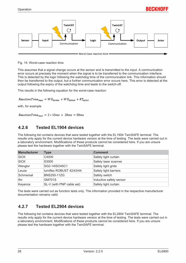
Fig. 14: Worst-case reaction time
This assumes that a signal change occurs at the sensor and is transmitted to the input. A communicationerror occurs at precisely the moment when the signal is to be transferred to the communication interface.This is detected by the logic following the watchdog time of the communication link. This information shouldthen be transferred to the output, but a further communication error occurs here. This error is detected at theoutput following the expiry of the watchdog time and leads to the switch-off.
This results in the following equation for the worst-case reaction:
with, for example
4.2.6 Tested EL1904 devicesThe following list contains devices that were tested together with the EL1904 TwinSAFE terminal. Theresults only apply for the current device hardware version at the time of testing. The tests were carried out ina laboratory environment. Modifications of these products cannot be considered here. If you are unsureplease test the hardware together with the TwinSAFE terminal.
Manufacturer Type CommentSICK C4000 Safety light curtainSICK S3000 Safety laser scannerWenglor SG2-14ISO45C1 Safety light gridsLeuze lumiflex ROBUST 42/43/44 Safety light barriersSchmersal BNS250-11ZG Safety switchifm GM701S Inductive safety sensorKeyence SL-V (with PNP cable set) Safety light curtain
The tests were carried out as function tests only. The information provided in the respective manufacturerdocumentation remains valid.
4.2.7 Tested EL2904 devicesThe following list contains devices that were tested together with the EL2904 TwinSAFE terminal. Theresults only apply for the current device hardware version at the time of testing. The tests were carried out ina laboratory environment. Modifications of these products cannot be considered here. If you are unsureplease test the hardware together with the TwinSAFE terminal.

Operation
EL6900 29Version: 2.2.0
Manufacturer Type CommentBeckhoff AX5801 TwinSAFE Drive option card: safe restart lockBeckhoff AX2000 AS option safe restart lockSiemens SIRIUS series S00
3RT1016-1BB42Contactor
Telemecanique LP1K09 Contactor
The tests were carried out as function tests only. The information provided in the respective manufacturerdocumentation remains valid.
Note
Recommended protective circuitsWe recommend R/C or diode-based protective circuits for these devices.Varistor-based protective circuits should not be used.
4.3 Operation in potentially explosive atmospheres (ATEX)
4.3.1 Special conditions
WARNING
Observe the special conditions for the intended use of Beckhoff fieldbuscomponents in potentially explosive areas (directive 94/9/EU)!The certified components are to be installed in a suitable housing that guarantees a protec-tion class of at least IP54 in accordance with EN 60529! The environmental conditions dur-ing use are thereby to be taken into account!If the temperatures during rated operation are higher than 70 °C at the feed-in points of ca-bles, lines or pipes, or higher than 80°C at the wire branching points, then cables must beselected whose temperature data correspond to the actual measured temperature values!Observe the permissible ambient temperature range of 0 to 55 °C when using Beckhofffieldbus components in potentially explosive atmospheres!Measures must be taken to protect against the rated operating voltage being exceeded bymore than 40% due to short-term interference voltages!The individual terminals may only be unplugged or removed from the Bus Terminal systemif the supply voltage has been switched off or if a non-explosive atmosphere is ensured!The connections of the certified components may only be connected or disconnected if thesupply voltage has been switched off or if a non-explosive atmosphere is ensured!The fuses of the EL92xx power feed terminals may only be exchanged if the supply voltagehas been switched off or if a non-explosive atmosphere is ensured!Address selectors and ID switches may only be adjusted if the supply voltage has beenswitched off or if a non-explosive atmosphere is ensured!
The fundamental health and safety requirements are fulfilled by compliance with the following standards:
• EN 60079-0: 2006• EN 60079-15: 2005

Operation
EL690030 Version: 2.2.0
4.3.2 IdentificationBeckhoff fieldbus components that are certified for use in potentially explosive atmospheres bear one of thefollowing markings:
II 3 G Ex nA II T4 KEMA 10ATEX0075 X Ta: 0 - 55°C
or
II 3 G Ex nA nC IIC T4 KEMA 10ATEX0075 X Ta: 0 - 55°C
4.3.3 Date code and serial numberThe TwinSAFE terminals bear a date code, which is composed as follows:
Date code: CW YY SW HW
Legend:CW: Calendar week of manufactureYY: Year of manufactureSW: Software versionHW: Hardware version
Sample: Date code 29 10 02 01Calendar week: 29Year: 2010Software version: 02Hardware version: 01
In addition the TwinSAFE terminals bear a unique serial number.
4.3.4 Further ATEX documentation
Note
Please also refer to the further documentationNotes regarding application of the Bus Terminal system in areas potentially explosive at-mosphere are available in the Download section of the Beckhoff website at http://www.beckhoff.de.
4.4 Configuration of the terminal in TwinCAT
CAUTION
Do not change CoE objects!Do not change any of the CoE objects in the TwinSAFE terminals. Any modifications (e.g.via TwinCAT) of the CoE objects will permanently set the terminals to the Fail-Stop state orlead to unexpected behavior of the terminals!
4.4.1 Configuration requirementsVersion 2.11 build 1544 or higher of the TwinCAT automation software is required for configuring theEL6900. The current version is available for download from the Beckhoff website (www.beckhoff.de).

Operation
EL6900 31Version: 2.2.0
4.4.2 Inserting a Bus CouplerSee TwinCAT automation software documentation.
4.4.3 Inserting a Bus TerminalSee TwinCAT automation software documentation.
4.4.4 Inserting an EL6900An EL6900 is inserted in the same way as any other Beckhoff Bus Terminal. In the list open SafetyTerminals (ELx9xx) and select the EL6900.
Fig. 15: Inserting an EL6900
Note
Size of the process imageThe process image of the EL6900 is adjusted dynamically based on the TwinSAFE configu-ration created in the TwinCAT automation software.

Operation
EL690032 Version: 2.2.0
4.4.5 Address settings on TwinSAFE terminals with 1023 possibleaddresses
Fig. 16: Address settings on TwinSAFE terminals with 1023 possible addresses
The TwinSAFE address of the terminal is set via the 10-way DIP switch on the left-hand side of theTwinSAFE terminal. TwinSAFE addresses between 1 and 1023 are available.
DIP switch Address1 2 3 4 5 6 7 8 9 10ON OFF OFF OFF OFF OFF OFF OFF OFF OFF 1OFF ON OFF OFF OFF OFF OFF OFF OFF OFF 2ON ON OFF OFF OFF OFF OFF OFF OFF OFF 3OFF OFF ON OFF OFF OFF OFF OFF OFF OFF 4ON OFF ON OFF OFF OFF OFF OFF OFF OFF 5OFF ON ON OFF OFF OFF OFF OFF OFF OFF 6ON ON ON OFF OFF OFF OFF OFF OFF OFF 7... ... ... ... ... ... ... ... ... ... ...ON ON ON ON ON ON ON ON ON ON 1023
WARNING
TwinSAFE addressEach TwinSAFE address may only be used once within a network / a configuration!The address 0 is not a valid TwinSAFE address!
4.4.6 Registering the TwinSAFE addresses in the TwinCATautomation software
The TwinSAFE address set at the DIP switch must also be entered under the TwinSAFE Logic tab(TwinSAFE address entry).
Operation
EL6900 33Version: 2.2.0
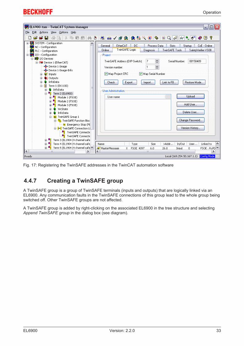
Fig. 17: Registering the TwinSAFE addresses in the TwinCAT automation software
4.4.7 Creating a TwinSAFE groupA TwinSAFE group is a group of TwinSAFE terminals (inputs and outputs) that are logically linked via anEL6900. Any communication faults in the TwinSAFE connections of this group lead to the whole group beingswitched off. Other TwinSAFE groups are not affected.
A TwinSAFE group is added by right-clicking on the associated EL6900 in the tree structure and selectingAppend TwinSAFE group in the dialog box (see diagram).

Operation
EL690034 Version: 2.2.0
Fig. 18: Creating a TwinSAFE group

Operation
EL6900 35Version: 2.2.0
4.4.8 TwinSAFE group signals
Fig. 19: TwinSAFE group signals
TwinSAFE group inputs
Name Permitted type DescriptionRUN FB-Out
Standard-InTRUE The function blocks assigned to the TwinSAFE group are executed.
When the input is not linked it is in the TRUE stateFALSE All of the TwinSAFE group assigned function blocks are at a STOP
state and thus all associated outputs are in a safe state.ERR Ack FB-Out
Standard-InAll pending errors in the assigned function blocks and in the TwinSAFEconnections are acknowledged by the FALSE->TRUE->FALSE signalsequence.
TwinSAFE group outputs
Name Permitted type DescriptionFB ERR TwinSAFE-Out
FB-InStandard-Out
TRUE At least one assigned function block has an errorFALSE All assigned function blocks have no errors
COMERR
TwinSAFE-OutFB-InStandard-Out
TRUE At least one TwinSAFE connection of TwinSAFE group has an errorFALSE All TwinSAFE connections of the TwinSAFE group have no errors
OUT ERR TwinSAFE-OutFB-InStandard-Out
FALSE Always FALSE, since the EL6900 has no local outputs

Operation
EL690036 Version: 2.2.0
4.4.9 Append a function blockThe EL6900 TwinSAFE logic terminal features function blocks like Emergency Stop, Machine Monitoring,AND, OR, Decoupler, Operation Mode, etc.
A function block is added by right-clicking on the associated TwinSAFE function block list in the treestructure and selecting Append Function Block in the dialog box with the left mouse button (see diagram).
Fig. 20: Appending a function block
The required function block can then be selected from the following window.
Fig. 21: Selection of the desired function block
Operation
EL6900 37Version: 2.2.0
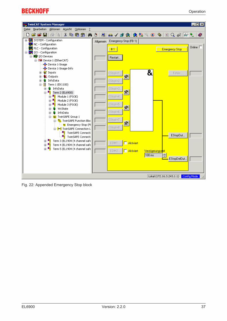
Fig. 22: Appended Emergency Stop block

Operation
EL690038 Version: 2.2.0
4.4.9.1 Activating and configuring the block inputs
Fig. 23: Function Block Input Settings
The following parameters can be set:
Deactivated: The input is not used
Single-channel: The inputs are linked independent of each other
Two-channel: The inputs are monitored for equality or inequality, depending on the contact type setting. ADiscrepancy Time can be set for monitoring the two inputs for simultaneous switching.
Make Contact: Contact type setting
Break Contact: Contact type setting
The inputs are now activated.
Fig. 24: Activated inputs
The inputs can now be linked.

Operation
EL6900 39Version: 2.2.0
Fig. 25: Link inputs
Select the variable type:
Fig. 26: Select the variable type
Clicking on the New button opens the following dialog:

Operation
EL690040 Version: 2.2.0
Fig. 27: Available channels
All available channels are displayed as selected.
The desired channel is selected and marked with the mouse. The selection is confirmed via the OK button.
Fig. 28: Selection of the desired channel
The name of the variables should now be entered in the Link Alias field.

Operation
EL6900 41Version: 2.2.0
Fig. 29: Enter alias
Repeat the process for the other inputs. Inputs that are already in use are identified with an arrow.
Fig. 30: Identification of inputs already in use
4.4.10 EL6900 user and version administrationThe EL6900 has a user administration function. The user Administrator can't be deleted, but its defaultpassword can and should be changed into a customer specific one. This is to be done via the button ChangePassword. The default password is TwinSAFE. The new password has to be 6 characters long at minimum.Up to 8 further users can be created.

Operation
EL690042 Version: 2.2.0
Fig. 31: EL6900 user administration
Via the button Upload the list of created users is read from the EL6900.
Fig. 32: User Administration - Upload
To create or delete users, the administrator password is needed.
By a left mouse click onto Add User… the dialog Login will be opened.

Operation
EL6900 43Version: 2.2.0
Fig. 33: User Administration - Login
If you enter the correct serial number and the valid administrator password, the Dialog Add User will open.
Fig. 34: User Administration - Add User
Enter the new User and twice the desired password.
The user name has to consist of one character at minimum and 16 characters at maximum. The newpassword has to be 6 characters long at minimum. The new user has the same rights like the administratorexcept the right to create or delete users. Via the button OK the data is assumed and displayed within theUser Administration.

Operation
EL690044 Version: 2.2.0
Fig. 35: User Administration - User List
To delete a user, the designed user has to be selected and via the button Delete User… the dialog DeleteUser will open.
Fig. 36: User Administration - Delete User
After entering the correct serial number and the valid administrator password the selected user can bedeleted via the button OK. The button Cancel finishes the procedure without changes.
To change the password of a user, the designed user has to be selected and via the button ChangePassword… the dialog Change Password will open.
Operation
EL6900 45Version: 2.2.0
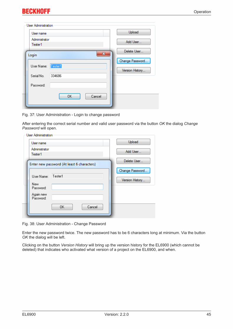
Fig. 37: User Administration - Login to change password
After entering the correct serial number and valid user password via the button OK the dialog ChangePassword will open.
Fig. 38: User Administration - Change Password
Enter the new password twice. The new password has to be 6 characters long at minimum. Via the buttonOK the dialog will be left.
Clicking on the button Version History will bring up the version history for the EL6900 (which cannot bedeleted) that indicates who activated what version of a project on the EL6900, and when.

Operation
EL690046 Version: 2.2.0
Fig. 39: Display of the version history
4.4.11 Export and import of a TwinSAFE project
Fig. 40: Export and import of a TwinSAFE project
Using the Export button you can export a safety project from a TwinCAT installation in XML format and thenimport this XML file into another TwinCAT installation using the Import button. During the import TwinCATattempts to restore the connections within the logic to the safe input and output terminals via the FSoEaddress. An error message is displayed if this is not possible.

Operation
EL6900 47Version: 2.2.0
4.4.12 EL6900 info data
Fig. 41: EL6900 info data
Info data can be displayed in the cyclic process image via the checkboxes Map Project CRC and Map SerialNumber. These info data show the current safety project CRC and the serial number of the EL6900 and canbe used in a visualization, for example.
4.4.13 Loading the project into the EL6900The project is loaded into the EL6900 via the fieldbus.
CAUTION
Use only qualified toolsOnly use a qualified tool for loading, verifying and enabling the project on the EL6900!
Click the Download button on the TwinSAFE Verifier tab for loading the project.
The user must enter
• his user name (default: Administrator),• the terminal serial number (printed on the outside, e.g. 197535), and• his password (default: TwinSAFE).
Note
User name and password are case-sensitivePay attention to upper/lower case characters for the user name and password.

Operation
EL690048 Version: 2.2.0
Fig. 42: Loading the project into the EL6900
The project is then displayed in text mode, and the user has to confirm consistency between the informationdisplayed and the currently projected application by re-entering the password. The project is then started onthe EL6900.
4.4.13.1 EL6900 project design limitsTwinSAFE connections max. 128 (with 1 or 2 bytes safe user data per connection)
max. 50 connections per TwinSAFE groupOnly 16 connections of an EL6900 can be slave connections.
Supported hardware for EL6900TwinSAFE connections
EL1904 (all)EL2904 (all)EL2902 (all)KL1904 (from 2008)KL2904 (from 2008)KL6904 as slave (from 2008)AX5805 (all)
Safe data per connection up to 14 bytes safe user data (correspondingly lower total number ofconnections)
TwinSAFE blocks 255 max.TwinSAFE groups 32 max.Standard PLC inputs dynamic up to 255 bitStandard PLC outputs dynamic up to 255 bit

Operation
EL6900 49Version: 2.2.0
Note
TwinSAFE connectionOnly one TwinSAFE connection between two TwinSAFE terminals is possible. Betweentwo EL6900 logic terminals a connection can be set up that may contain up to 14 bytessafe user data.
4.4.14 Communication between TwinCAT controllersThe MASTER_MESSAGE and SLAVE_MESSAGE data types are used for communication between two ormore TwinCAT controllers via network variables.
Associated variables have to be created under Publisher and Subscriber on the communicating controllers.
During TwinSAFE communication one side acts as the master, the other one as the slave.
This results in the following data types:
TwinSAFE Master PublisherTwinSAFE Master SubscriberTwinSAFE Slave PublisherTwinSAFE Slave Subscriber
MASTER_MESSAGESLAVE_MESSAGESLAVE_MESSAGEMASTER_MESSAGE
The link with the TwinSAFE logic terminal EL6900 is established with the following dialog.
Fig. 43: Link with the TwinSAFE logic terminal EL6900
The connection created must now be made known to the TwinSAFE logic terminal. This is done by markingthe TwinSAFE connection list and pressing the right mouse button.
Fig. 44: Make known the connection created to the TwinSAFE logic terminal

Operation
EL690050 Version: 2.2.0
Create a new connection in the list of connections and create associated variables of the required type underModule1 (FSoE).
Fig. 45: Creation of a variable for the master message
Fig. 46: Creation of a variable for the slave message
These newly-created variables are now linked with the network variables already created. This is carried outfor both the master and the slave message.

Operation
EL6900 51Version: 2.2.0
Fig. 47: Linking the variables
The settings for the TwinSAFE connection can then be set, including FSoE address, FSoE watchdog and thecommunication device type. In addition, the connection can be identified as FSoE master or FSoE slaves,and the information to be mapped in the cyclic process image can be specified.
Fig. 48: Settings for the TwinSAFE connection
If several connections are to be established, a unique ID must be set for each Publisher variable.
Operation
EL690052 Version: 2.2.0
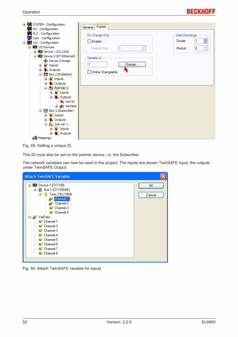
Fig. 49: Setting a unique ID
This ID must also be set on the partner device, i.e. the Subscriber.
The network variables can now be used in the project. The inputs are shown TwinSAFE Input, the outputsunder TwinSAFE Output.
Fig. 50: Attach TwinSAFE variable for inputs

Operation
EL6900 53Version: 2.2.0
Fig. 51: Attach TwinSAFE variable for outputs
4.5 Diagnostics
4.5.1 Diagnostic LEDsThe LEDs Diag 1 to Diag 4 display diagnostic information for the EL6900.
Fig. 52: EL6900 diagnostic LEDs
4.5.1.1 Diag 1 LED (green)
The Diag 1 LED is currently always on when a project is loaded into the terminal.
Display Meaninglit A project is stored in the terminal.
4.5.1.2 Diag 2 LED (red)
The Diag 2 LED indicates internal process variable errors (in preparation).
Display Meaning- in preparation
Operation
EL690054 Version: 2.2.0
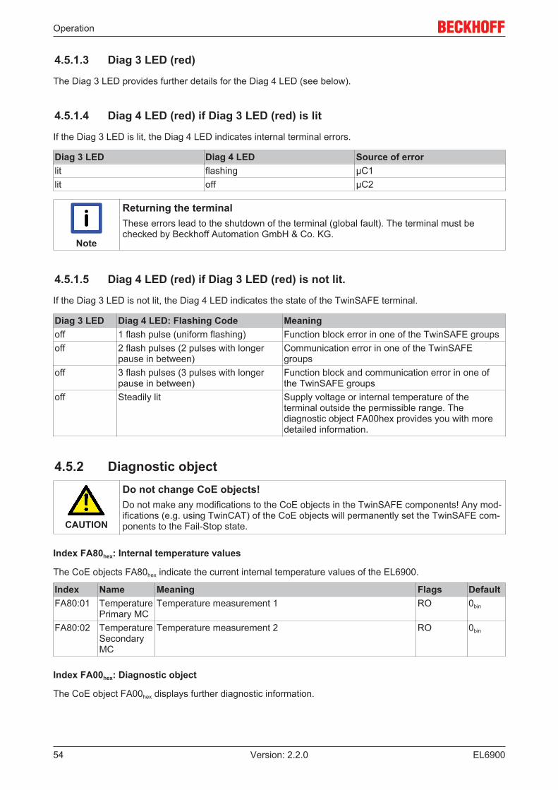
4.5.1.3 Diag 3 LED (red)
The Diag 3 LED provides further details for the Diag 4 LED (see below).
4.5.1.4 Diag 4 LED (red) if Diag 3 LED (red) is lit
If the Diag 3 LED is lit, the Diag 4 LED indicates internal terminal errors.
Diag 3 LED Diag 4 LED Source of errorlit flashing µC1lit off µC2
Note
Returning the terminalThese errors lead to the shutdown of the terminal (global fault). The terminal must bechecked by Beckhoff Automation GmbH & Co. KG.
4.5.1.5 Diag 4 LED (red) if Diag 3 LED (red) is not lit.
If the Diag 3 LED is not lit, the Diag 4 LED indicates the state of the TwinSAFE terminal.
Diag 3 LED Diag 4 LED: Flashing Code Meaningoff 1 flash pulse (uniform flashing) Function block error in one of the TwinSAFE groupsoff 2 flash pulses (2 pulses with longer
pause in between)Communication error in one of the TwinSAFEgroups
off 3 flash pulses (3 pulses with longerpause in between)
Function block and communication error in one ofthe TwinSAFE groups
off Steadily lit Supply voltage or internal temperature of theterminal outside the permissible range. Thediagnostic object FA00hex provides you with moredetailed information.
4.5.2 Diagnostic object
CAUTION
Do not change CoE objects!Do not make any modifications to the CoE objects in the TwinSAFE components! Any mod-ifications (e.g. using TwinCAT) of the CoE objects will permanently set the TwinSAFE com-ponents to the Fail-Stop state.
Index FA80hex: Internal temperature values
The CoE objects FA80hex indicate the current internal temperature values of the EL6900.
Index Name Meaning Flags DefaultFA80:01 Temperature
Primary MCTemperature measurement 1 RO 0bin
FA80:02 TemperatureSecondaryMC
Temperature measurement 2 RO 0bin
Index FA00hex: Diagnostic object
The CoE object FA00hex displays further diagnostic information.

Operation
EL6900 55Version: 2.2.0
Index Name Meaning Flags DefaultFA00:0 Diag The following sub-indices contain detailed diagnostic
information.RO
FA00:03 Temperatureerror
0005hex Maximum temperature exceeded RO 0000hex
0006hex Temperature fell below minimum0007hex Temperature difference between the measuring
points exceededSupply error 0101hex max. supply voltage µC1 exceeded
0102hex max. supply voltage µC2 exceeded0103hex voltage fell below min. supply voltage µC10104hex voltage fell below min. supply voltage µC2
Note
Differing diagnostic messages possibleDue to the variable order or execution of the test series, diagnostic messages differing fromthose given in the table above are possible.
Index F100hex: Device Status
This CoE object is also mapped to the EL6900 process image under DEVICE Inputs.
Index Name Meaning Data type FlagsF100:01 Safety
Project StateState of the Safety Logic Project BIT3 RO0 OFFLINE
Safety Project not loaded1 RUN
Safety Project is executed, EtherCAT is in SAFEOPor OP state
2 STOPSafety Project is loaded, but is stopped, due to alogged in user
3 STARTSafety Project is loaded, EtherCAT is in INIT orPREOP state
4 RESTOREWhen RESTORE Mode is configured: Project CRC isread from the FSoE Slaves
7 FAULTThe EL6900 has switched off due to a severe fault. Asafety project can not be loaded or started.
F100:08 Login Active A user is logged in to the EL6900 BOOLEAN ROF100:09 Input Size
MismatchThe length of the input data does not match the input datalength calculated from the safety Logic
BOOLEAN RO
F100:0A Output SizeMismatch
The length of the output data does not match the output datalength calculated from the safety Logic
BOOLEAN RO
F100:0F TxPDOState
This bit is set, when the Safety Project State is unequal toRUN
BOOLEAN RO
F100:10 TxPDOToggle
This bit is toggled each time the EtherCAT input data isupdated for the first time after it has been read by theEtherCAT master.
BOOLEAN RO

Operation
EL690056 Version: 2.2.0
4.5.3 Cycle time of the safety project
Index 1C32hex: Cycle Time Measuring
Index Name Meaning Flags Default1C32:05 Minimum cycle
timeMinimum cycle time in ns that should be set byEtherCAT. Corresponds to the maximum programrunning time of the EL6900.
RO 00000000hex
1C32:08 Command Cycle time measurement is activated by setting thecommand to 0001hex. This value should be reset to0 once the cycle time has been determined.
RW 0000hex
4.5.4 Status LEDsThe LEDs State 1 to State 4 indicate the current status of the EL6900.
Fig. 53: EL6900 status LEDs
State 1 State 2 State 3 State 4 Meaningoff off off lit • No project present on the terminaloff off lit lit • Project present on the terminal
• EtherCAT status: Pre-Operational (Pre-OP)lit lit lit lit • Project present on the terminal
• EtherCAT status: Operational (OP)
4.6 Maintenance
Maintenance
The TwinSAFE components are maintenance-free!
Environmental conditions
WARNING
Observe the specified environmental conditions!Please ensure that the TwinSAFE components are only stored and operated under thespecified conditions (see technical data).
If the TwinSAFE component is operated outside the permitted temperature range it will switch to GlobalShutdown state.
Cleaning
Protect the TwinSAFE component from unacceptable soling during operation and storage!
If the TwinSAFE component was subjected to unacceptable soiling it may no longer be operated!

Operation
EL6900 57Version: 2.2.0
WARNING
Have soiled terminals checked!Cleaning of the TwinSAFE component by the user is not permitted!Please send soiled terminals to the manufacturer for inspection and cleaning!
4.7 Service lifeThe TwinSAFE terminals are designed for a service life of 20 years.
Due to the high diagnostic coverage within the lifecycle no special proof tests are required.
The TwinSAFE terminals bear a date code, which is composed as follows:
Date code: CW YY SW HW
Legend:CW: Calendar week of manufactureYY: Year of manufactureSW: Software versionHW: Hardware version
Sample: Date Code 17 11 05 00Calendar week: 17Year: 2011Software version: 05Hardware version: 00
In addition the TwinSAFE terminals bear a unique serial number.
Fig. 54: Unique serial number of a TwinSAFE terminal
4.8 Decommissioning
DANGER
Serious risk of injury!Bring the bus system into a safe, de-energized state before starting disassembly of the de-vices!
Disposal
In order to dispose of the device, it must be removed and fully dismantled.
• Housing components (polycarbonate, polyamide (PA6.6)) are suitable for plastic recycling.• Metal parts can be sent for metal recycling.• Electronic parts such as disk drives and circuit boards must be disposed of in accordance with national
electronics scrap regulations.

Appendix
EL690058 Version: 2.2.0
5 Appendix
5.1 Support and ServiceBeckhoff and their partners around the world offer comprehensive support and service, making available fastand competent assistance with all questions related to Beckhoff products and system solutions.
Beckhoff's branch offices and representatives
Please contact your Beckhoff branch office or representative for local support and service on Beckhoffproducts!
The addresses of Beckhoff's branch offices and representatives round the world can be found on her internetpages:http://www.beckhoff.com
You will also find further documentation for Beckhoff components there.
Beckhoff Headquarters
Beckhoff Automation GmbH & Co. KG
Huelshorstweg 2033415 VerlGermany
Phone: +49(0)5246/963-0Fax: +49(0)5246/963-198e-mail: [email protected]
Beckhoff Support
Support offers you comprehensive technical assistance, helping you not only with the application ofindividual Beckhoff products, but also with other, wide-ranging services:
• support• design, programming and commissioning of complex automation systems• and extensive training program for Beckhoff system components
Hotline: +49(0)5246/963-157Fax: +49(0)5246/963-9157e-mail: [email protected]
Beckhoff Service
The Beckhoff Service Center supports you in all matters of after-sales service:
• on-site service• repair service• spare parts service• hotline service
Hotline: +49(0)5246/963-460Fax: +49(0)5246/963-479e-mail: [email protected]

Appendix
EL6900 59Version: 2.2.0
5.2 Certificates

Appendix
EL690060 Version: 2.2.0

List of illustrations
EL6900 61Version: 2.2.0
List of illustrationsFig. 1 Slot and key system and screwless (spring-loaded) connection system..................................... 9Fig. 2 Bus Coupler (EtherCAT).............................................................................................................. 10Fig. 3 TwinSAFE Terminals (EtherCAT)................................................................................................ 11Fig. 4 EL6900 - TwinSAFE logic terminal .............................................................................................. 14Fig. 5 Dimensions of the EL6900........................................................................................................... 18Fig. 6 Installation position and minimum distances ............................................................................... 20Fig. 7 Example configuration for temperature measurement................................................................. 21Fig. 8 Installation on the mounting rail ................................................................................................... 22Fig. 9 Removal of mounting rails ........................................................................................................... 23Fig. 10 PE power contact......................................................................................................................... 24Fig. 11 Connection of a cable to a terminal point .................................................................................... 25Fig. 12 EL6900/EL6910 pin assignment.................................................................................................. 26Fig. 13 Typical reaction time.................................................................................................................... 27Fig. 14 Worst-case reaction time ............................................................................................................. 28Fig. 15 Inserting an EL6900..................................................................................................................... 31Fig. 16 Address settings on TwinSAFE terminals with 1023 possible addresses ................................... 32Fig. 17 Registering the TwinSAFE addresses in the TwinCAT automation software .............................. 33Fig. 18 Creating a TwinSAFE group ........................................................................................................ 34Fig. 19 TwinSAFE group signals ............................................................................................................. 35Fig. 20 Appending a function block.......................................................................................................... 36Fig. 21 Selection of the desired function block ........................................................................................ 36Fig. 22 Appended Emergency Stop block ............................................................................................... 37Fig. 23 Function Block Input Settings ...................................................................................................... 38Fig. 24 Activated inputs ........................................................................................................................... 38Fig. 25 Link inputs.................................................................................................................................... 39Fig. 26 Select the variable type ............................................................................................................... 39Fig. 27 Available channels....................................................................................................................... 40Fig. 28 Selection of the desired channel.................................................................................................. 40Fig. 29 Enter alias.................................................................................................................................... 41Fig. 30 Identification of inputs already in use........................................................................................... 41Fig. 31 EL6900 user administration ......................................................................................................... 42Fig. 32 User Administration - Upload....................................................................................................... 42Fig. 33 User Administration - Login ......................................................................................................... 43Fig. 34 User Administration - Add User ................................................................................................... 43Fig. 35 User Administration - User List .................................................................................................... 44Fig. 36 User Administration - Delete User ............................................................................................... 44Fig. 37 User Administration - Login to change password ........................................................................ 45Fig. 38 User Administration - Change Password..................................................................................... 45Fig. 39 Display of the version history....................................................................................................... 46Fig. 40 Export and import of a TwinSAFE project.................................................................................... 46Fig. 41 EL6900 info data.......................................................................................................................... 47Fig. 42 Loading the project into the EL6900 ............................................................................................ 48Fig. 43 Link with the TwinSAFE logic terminal EL6900 ........................................................................... 49Fig. 44 Make known the connection created to the TwinSAFE logic terminal ......................................... 49
List of illustrations
EL690062 Version: 2.2.0
Fig. 45 Creation of a variable for the master message............................................................................ 50Fig. 46 Creation of a variable for the slave message .............................................................................. 50Fig. 47 Linking the variables .................................................................................................................... 51Fig. 48 Settings for the TwinSAFE connection ........................................................................................ 51Fig. 49 Setting a unique ID ...................................................................................................................... 52Fig. 50 Attach TwinSAFE variable for inputs ........................................................................................... 52Fig. 51 Attach TwinSAFE variable for outputs ......................................................................................... 53Fig. 52 EL6900 diagnostic LEDs ............................................................................................................. 53Fig. 53 EL6900 status LEDs .................................................................................................................... 56Fig. 54 Unique serial number of a TwinSAFE terminal............................................................................ 57