operating instructions and parts manual model pm2700...
TRANSCRIPT
Operating Instructions and Parts Manual Model PM2700 Shaper Model: 2700
Powermatic 427 New Sanford Road LaVergne, TN 37086 Part No. M-1280100C Ph.: 800-274-6848 Revision G1 02/2014 www.powermatic.com Copyright © 2014 Powermatic

2
Warranty and Service Powermatic warrants every product it sells against manufacturers’ defects. If one of our tools needs service or repair, please contact Technical Service by calling 1-800-274-6846, 8AM to 5PM CST, Monday through Friday.
Warranty Period The general warranty lasts for the time period specified in the literature included with your product or on the official Powermatic branded website.
• Powermatic products carry a limited warranty which varies in duration based upon the product. (See chart below)
• Accessories carry a limited warranty of one year from the date of receipt. • Consumable items are defined as expendable parts or accessories expected to become inoperable within a
reasonable amount of use and are covered by a 90 day limited warranty against manufacturer’s defects.
Who is Covered This warranty covers only the initial purchaser of the product from the date of delivery.
What is Covered This warranty covers any defects in workmanship or materials subject to the limitations stated below. This warranty does not cover failures due directly or indirectly to misuse, abuse, negligence or accidents, normal wear-and-tear, improper repair, alterations or lack of maintenance.
Warranty Limitations Woodworking products with a Five Year Warranty that are used for commercial or industrial purposes default to a Two Year Warranty. Please contact Technical Service at 1-800-274-6846 for further clarification.
How to Get Technical Support Please contact Technical Service by calling 1-800-274-6846. Please note that you will be asked to provide proof of initial purchase when calling. If a product requires further inspection, the Technical Service representative will explain and assist with any additional action needed. Powermatic has Authorized Service Centers located throughout the United States. For the name of an Authorized Service Center in your area call 1-800-274-6846 or use the Service Center Locator on the Powermatic website.
More Information Powermatic is constantly adding new products. For complete, up-to-date product information, check with your local distributor or visit the Powermatic website.
How State Law Applies This warranty gives you specific legal rights, subject to applicable state law.
Limitations on This Warranty POWERMATIC LIMITS ALL IMPLIED WARRANTIES TO THE PERIOD OF THE LIMITED WARRANTY FOR EACH PRODUCT. EXCEPT AS STATED HEREIN, ANY IMPLIED WARRANTIES OF MERCHANTABILITY AND FITNESS FOR A PARTICULAR PURPOSE ARE EXCLUDED. SOME STATES DO NOT ALLOW LIMITATIONS ON HOW LONG AN IMPLIED WARRANTY LASTS, SO THE ABOVE LIMITATION MAY NOT APPLY TO YOU. POWERMATIC SHALL IN NO EVENT BE LIABLE FOR DEATH, INJURIES TO PERSONS OR PROPERTY, OR FOR INCIDENTAL, CONTINGENT, SPECIAL, OR CONSEQUENTIAL DAMAGES ARISING FROM THE USE OF OUR PRODUCTS. SOME STATES DO NOT ALLOW THE EXCLUSION OR LIMITATION OF INCIDENTAL OR CONSEQUENTIAL DAMAGES, SO THE ABOVE LIMITATION OR EXCLUSION MAY NOT APPLY TO YOU. Powermatic sells through distributors only. The specifications listed in Powermatic printed materials and on the official Powermatic website are given as general information and are not binding. Powermatic reserves the right to effect at any time, without prior notice, those alterations to parts, fittings, and accessory equipment which they may deem necessary for any reason whatsoever.
Product Listing with Warranty Period 90 Days – Parts; Consumable items 1 Year – Woodworking Machinery used for industrial or commercial purposes 5 Year – Woodworking Machinery
NOTE: Powermatic is a division of JPW Industries, Inc. References in this document to Powermatic also apply to JPW Industries, Inc., or any of its successors in interest to the Powermatic brand.

3
Table of Contents Warranty and Service .............................................................................................................................. 2 Table of Contents .................................................................................................................................... 3 Warnings ................................................................................................................................................. 4 Warning ................................................................................................................................................... 6 Introduction ............................................................................................................................................. 7 Specifications .......................................................................................................................................... 7 Unpacking ............................................................................................................................................... 8
Shipping Contents ................................................................................................................................ 8 Installing .................................................................................................................................................. 8 Assembly ................................................................................................................................................ 9
Mounting the Fence ............................................................................................................................. 9 Electrical Connections ............................................................................................................................. 9
General Information ............................................................................................................................. 9 Extension Cords................................................................................................................................. 10
Adjustments .......................................................................................................................................... 11 Fence Assembly Movement ............................................................................................................... 11 Coplanar Alignment............................................................................................................................ 12 Ram Dial Calibration .......................................................................................................................... 13 Spindle Gib Adjustment ...................................................................................................................... 14 Featherboard Hold-downs .................................................................................................................. 14 Spindle Assembly Installation ............................................................................................................. 15 Spindle Assembly Removal ................................................................................................................ 15 Shaper Cutter Installation ................................................................................................................... 16 Router Collet (Optional) Installation .................................................................................................... 16 Changing Cutter Speed ...................................................................................................................... 17 Drive Belt Tension .............................................................................................................................. 17 Precision Miter Gauge ........................................................................................................................ 18 Handwheel Adjustments ..................................................................................................................... 11 Belt Replacement ............................................................................................................................... 17
Operating Controls ................................................................................................................................ 19 Start/Stop ........................................................................................................................................... 19 Safety Key ......................................................................................................................................... 19 Digital Readout .................................................................................................................................. 19
Operations............................................................................................................................................. 20 Special Cuts .......................................................................................................................................... 29 Troubleshooting for PM2700 Shaper...................................................................................................... 32 Optional Accessories ............................................................................................................................. 33 Parts ..................................................................................................................................................... 34
Ordering Replacement Parts .............................................................................................................. 34 Table – Parts List ............................................................................................................................... 34 Table – Assembly Drawing ................................................................................................................. 35 Fence – Parts List .............................................................................................................................. 36 Fence – Assembly Drawing ................................................................................................................ 37 Frame and Motor – Parts List ............................................................................................................. 38 Elevator – Parts List ........................................................................................................................... 40 Elevator – Assembly Drawing ............................................................................................................. 41 Caster Assembly – Parts List ............................................................................................................. 42 Caster Assembly Drawing .................................................................................................................. 43 Spindle Assembly – Parts List ............................................................................................................ 44 Spindle Assembly Drawing- ................................................................................................................ 45 Cabinet and Base – Parts List ............................................................................................................ 46 Cabinet and Base .............................................................................................................................. 48
Wiring Diagrams .................................................................................................................................... 49 3HP/5HP, 230V, 1Phase .................................................................................................................... 49 5HP, 230V, 3Phase............................................................................................................................ 50 5HP, 460V, 3Phase............................................................................................................................ 51

4
Warnings
1. Read and understand the entire owner's manual before attempting assembly or operation.
2. Read and understand the warnings posted on the machine and in this manual. Failure to comply with all of these warnings may cause serious injury.
3. Replace the warning labels if they become obscured or removed.
4. This shaper is designed and intended for use by properly trained and experienced personnel only. If you are not familiar with the proper and safe operation of a shaper, do not use until proper training and knowledge have been obtained.
5. Do not use this shaper for other than its intended use. If used for other purposes, Powermatic disclaims any real or implied warranty and holds itself harmless from any injury that may result from that use.
6. Always wear approved safety glasses/face shields while using this shaper. Everyday eyeglasses only have impact resistant lenses; they are not safety glasses.
7. Before operating this shaper, remove tie, rings, watches and other jewelry, and roll sleeves up past the elbows. Remove all loose clothing and confine long hair. Non-slip footwear or anti-skid floor strips are recommended. Do not wear gloves.
8. Wear ear protectors (plugs or muffs) during extended periods of operation.
9. Some dust created by power sanding, shaping, grinding, drilling and other construction activities contain chemicals known to cause cancer, birth defects or other reproductive harm. Some examples of these chemicals are:
• Lead from lead based paint. • Crystalline silica from bricks, cement and other masonry products. • Arsenic and chromium from chemically treated lumber.
Your risk of exposure varies, depending on how often you do this type of work. To reduce your exposure to these chemicals, work in a well-ventilated area and work with approved safety equipment, such as face or dust masks that are specifically designed to filter out microscopic particles.
10. Do not operate this machine while tired or under the influence of drugs, alcohol or any medication.
11. Make certain the machine is properly grounded.
12. Make all machine adjustments or maintenance with the machine unplugged from the power source. A machine under repair should be RED TAGGED to show it must not be used until maintenance is complete.
13. Remove adjusting keys and wrenches. Form a habit of checking to see that keys and adjusting wrenches are removed from the machine before turning it on.
14. Keep safety guards in place at all times when the machine is in use. If removed for maintenance purposes, use extreme caution and replace the guards immediately.
15. Check damaged parts. Before further use of the machine, a guard or other part that is damaged should be carefully checked to determine that it will operate properly and perform its intended function. Check for alignment of moving parts, binding of moving parts, breakage of parts, mounting and any other conditions that may affect its operation. A guard or other part that is damaged should be properly repaired or replaced.
16. Provide for adequate space surrounding work area and non-glare, overhead lighting.
17. Keep the floor around the machine clean and free of scrap material, oil and grease.
18. Keep visitors a safe distance from the work area. Keep children away.

5
19. Make your workshop child proof with padlocks, master switches or by removing safety keys.
20. Keep visitors a safe distance from the work area. Keep children away.
21. Make your workshop child proof with padlocks, master switches or by removing safety keys.
22. Give your work undivided attention. Looking around, carrying on a conversation and “horse-play” are careless acts that can result in serious injury.
23. Maintain a balanced stance at all times so that you do not fall or lean against the blade or other moving parts. Do not overreach or use excessive force to perform any machine operation.
24. Use the right tool at the correct speed and feed rate. Do not force a tool or attachment to do a job for which it was not designed. The right tool will do the job better and safer.
25. Use recommended accessories; improper accessories may be hazardous.
26. Maintain tools with care. Keep cutter sharp and clean for the best and safest performance. Follow instructions for lubricating and changing accessories.
27. Check the cutter for cracks or missing teeth. Do not use a cracked cutter or one with missing teeth or improper set. Make sure the cutter is securely locked on the arbor.
28. Keep hands clear of the cutter area. Do not reach past the cutter to clear parts or scrap with the shaper running. Avoid awkward operations and hand positions where a sudden slip could cause your hand to contact the cutter.
29. Do not attempt to shape boards with loose knots or with nails or other foreign material, on its surface. Do not attempt to shape twisted, warped, bowed or “in wind” stock unless one edge has been jointed for guiding purposes prior to shaping.
30. Do not attempt to shape long or wide boards unsupported where spring or weight could cause the board to shift position.
31. Always use safety devices for all operations where they can be used.
32. Be sure to check the direction of spindle rotation before use.
33. Turn off the machine before cleaning. Use a brush or compressed air to remove chips or debris — do not use your hands.
34. Do not stand on the machine. Serious injury could occur if the machine tips over.
35. Never leave the machine running unattended. Turn the power off and do not leave the machine until it comes to a complete stop.
36. Remove loose items and unnecessary work pieces from the area before starting the machine.
Familiarize yourself with the following safety notices used in this manual:
This means that if precautions are not heeded, it may result in minor injury and/or possible machine damage.
This means that if precautions are not heeded, it may result in serious injury or possibly even death.
6
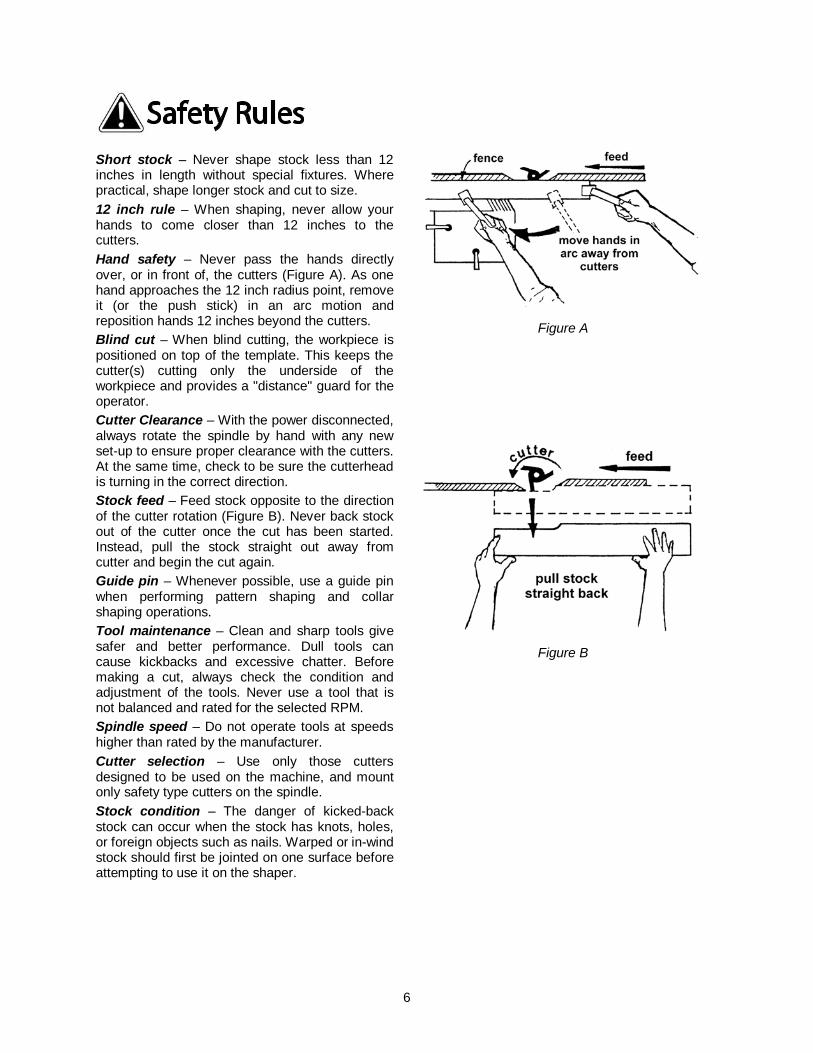
Warning Short stock – Never shape stock less than 12 inches in length without special fixtures. Where practical, shape longer stock and cut to size. 12 inch rule – When shaping, never allow your hands to come closer than 12 inches to the cutters. Hand safety – Never pass the hands directly over, or in front of, the cutters (Figure A). As one hand approaches the 12 inch radius point, remove it (or the push stick) in an arc motion and reposition hands 12 inches beyond the cutters. Blind cut – When blind cutting, the workpiece is positioned on top of the template. This keeps the cutter(s) cutting only the underside of the workpiece and provides a "distance" guard for the operator. Cutter Clearance – With the power disconnected, always rotate the spindle by hand with any new set-up to ensure proper clearance with the cutters. At the same time, check to be sure the cutterhead is turning in the correct direction. Stock feed – Feed stock opposite to the direction of the cutter rotation (Figure B). Never back stock out of the cutter once the cut has been started. Instead, pull the stock straight out away from cutter and begin the cut again. Guide pin – Whenever possible, use a guide pin when performing pattern shaping and collar shaping operations. Tool maintenance – Clean and sharp tools give safer and better performance. Dull tools can cause kickbacks and excessive chatter. Before making a cut, always check the condition and adjustment of the tools. Never use a tool that is not balanced and rated for the selected RPM. Spindle speed – Do not operate tools at speeds higher than rated by the manufacturer. Cutter selection – Use only those cutters designed to be used on the machine, and mount only safety type cutters on the spindle. Stock condition – The danger of kicked-back stock can occur when the stock has knots, holes, or foreign objects such as nails. Warped or in-wind stock should first be jointed on one surface before attempting to use it on the shaper.
Figure A
Figure B

7
Introduction This manual is provided by Powermatic covering the safe operation and maintenance procedures for a Powermatic Model PM2700 Shaper. This manual contains instructions on installation, safety precautions, general operating procedures, maintenance instructions and parts breakdown. This machine has been designed and constructed to provide years of trouble free operation if used in accordance with instructions set forth in this manual. If there are any questions or comments, please contact either your local supplier or Powermatic. Powermatic can also be reached at our web site: www.powermatic.com.
Specifications Model Number .............................................................................................................................. PM2700
Motor (TEFC Capacitor Start Induction) Stock Number 3HP, 1 Phase, 230V, 60Hz, 14A .............................................................................................. 1280100C 5HP, 1 Phase, 230V, 60Hz, 22A .............................................................................................. 1280101C 5HP, 3 Phase, 230V/460V-prewired 230V (for 460V see Note below), 60Hz, 13/6.5A .............. 1280102C Table Size (L x W) ....................................................................................................................... 40" x 30" Table Height from Floor .................................................................................................................. 35-1/2” Spindle Size (Standard) .................................................................................. 3/4", 1-1/4" Interchangeable Router Bit Collet Size (Optional) .................................................................................................. 1/4", 1/2" Spindle Capacity Under Nut: 3/4” Spindle (provided).............................................................................................................. 3-27/64" 1-1/4” Spindle (provided) ............................................................................................................ 5-5/32” 1” Spindle (optional accessory) ................................................................................................. 4-59/64” Spindle Travel ........................................................................................................................................ 4" Spindle Speeds (RPM) .......................................................................................... 7500, 10000, reversible Table Opening Diameter .................................................................................................................... 7.33" Insert Opening Diameters .............................................................................................. 2.55", 4.16", 5.75" Fence Size (x 2) .................................................................................................... 4-7/8" (H) x 18-3/4" (W) Dust Collection Minimum CFM Required .............................................................................................. 600 Dust Port Diameter ................................................................................................................................. 4” Overall Dimensions .......................................................................................... 40" (L) x 37" (W) x 45" (H) Weight ..................................................................................................... 690 lbs (Shipping), 664 lbs (Net) Note: For 460V operation, magnetic switch (Part No. PM2700-114C) must be purchased separately and installed. A qualified electrician is recommended. The above specifications were current at the time this manual was published, but because of our policy of continuous improvement, Powermatic reserves the right to change specifications at any time and without prior notice, without incurring obligations.
Read and understand the entire contents of this manual before attempting assembly or operation! Failure to comply may cause serious injury.
8
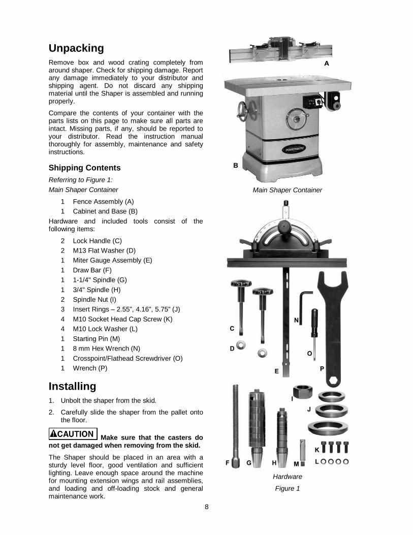
Unpacking Remove box and wood crating completely from around shaper. Check for shipping damage. Report any damage immediately to your distributor and shipping agent. Do not discard any shipping material until the Shaper is assembled and running properly.
Compare the contents of your container with the parts lists on this page to make sure all parts are intact. Missing parts, if any, should be reported to your distributor. Read the instruction manual thoroughly for assembly, maintenance and safety instructions.
Shipping Contents Referring to Figure 1: Main Shaper Container
1 Fence Assembly (A) 1 Cabinet and Base (B) Hardware and included tools consist of the following items:
2 Lock Handle (C) 2 M13 Flat Washer (D) 1 Miter Gauge Assembly (E) 1 Draw Bar (F) 1 1-1/4" Spindle (G) 1 3/4" Spindle (H) 2 Spindle Nut (I) 3 Insert Rings – 2.55”, 4.16”, 5.75” (J) 4 M10 Socket Head Cap Screw (K) 4 M10 Lock Washer (L) 1 Starting Pin (M) 1 8 mm Hex Wrench (N) 1 Crosspoint/Flathead Screwdriver (O) 1 Wrench (P)
Installing 1. Unbolt the shaper from the skid.
2. Carefully slide the shaper from the pallet onto the floor.
Make sure that the casters do not get damaged when removing from the skid.
The Shaper should be placed in an area with a sturdy level floor, good ventilation and sufficient lighting. Leave enough space around the machine for mounting extension wings and rail assemblies, and loading and off-loading stock and general maintenance work.
Main Shaper Container
Hardware
Figure 1
9
Cleaning
Exposed metal surfaces, such as the table top and extension wings, have been given a protective coating at the factory. This should be removed with a soft cloth moistened with kerosene. Do not use acetone, gasoline, or lacquer thinner for this purpose. Do not use solvents on plastic parts, and do not use an abrasive pad because it may scratch the surfaces.
Assembly Mounting the Fence Referring to Figure 2:
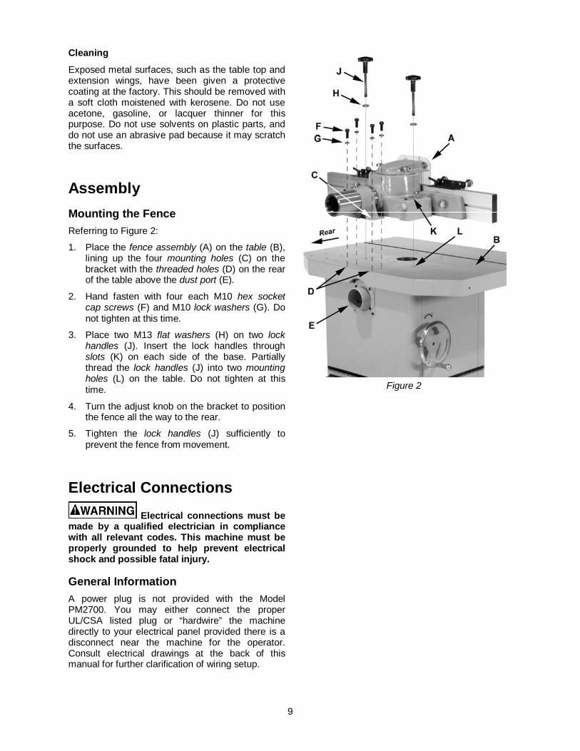
1. Place the fence assembly (A) on the table (B), lining up the four mounting holes (C) on the bracket with the threaded holes (D) on the rear of the table above the dust port (E).
2. Hand fasten with four each M10 hex socket cap screws (F) and M10 lock washers (G). Do not tighten at this time.
3. Place two M13 flat washers (H) on two lock handles (J). Insert the lock handles through slots (K) on each side of the base. Partially thread the lock handles (J) into two mounting holes (L) on the table. Do not tighten at this time.
4. Turn the adjust knob on the bracket to position the fence all the way to the rear.
5. Tighten the lock handles (J) sufficiently to prevent the fence from movement.
Electrical Connections
Electrical connections must be made by a qualified electrician in compliance with all relevant codes. This machine must be properly grounded to help prevent electrical shock and possible fatal injury.
General Information A power plug is not provided with the Model PM2700. You may either connect the proper UL/CSA listed plug or “hardwire” the machine directly to your electrical panel provided there is a disconnect near the machine for the operator. Consult electrical drawings at the back of this manual for further clarification of wiring setup.
Figure 2
10
This machine must be grounded. Grounding provides a path of least resistance to help divert current away from the operator in case of electrical malfunction.
Make sure the voltage of your power supply matches the specifications on the motor plate of the machine.
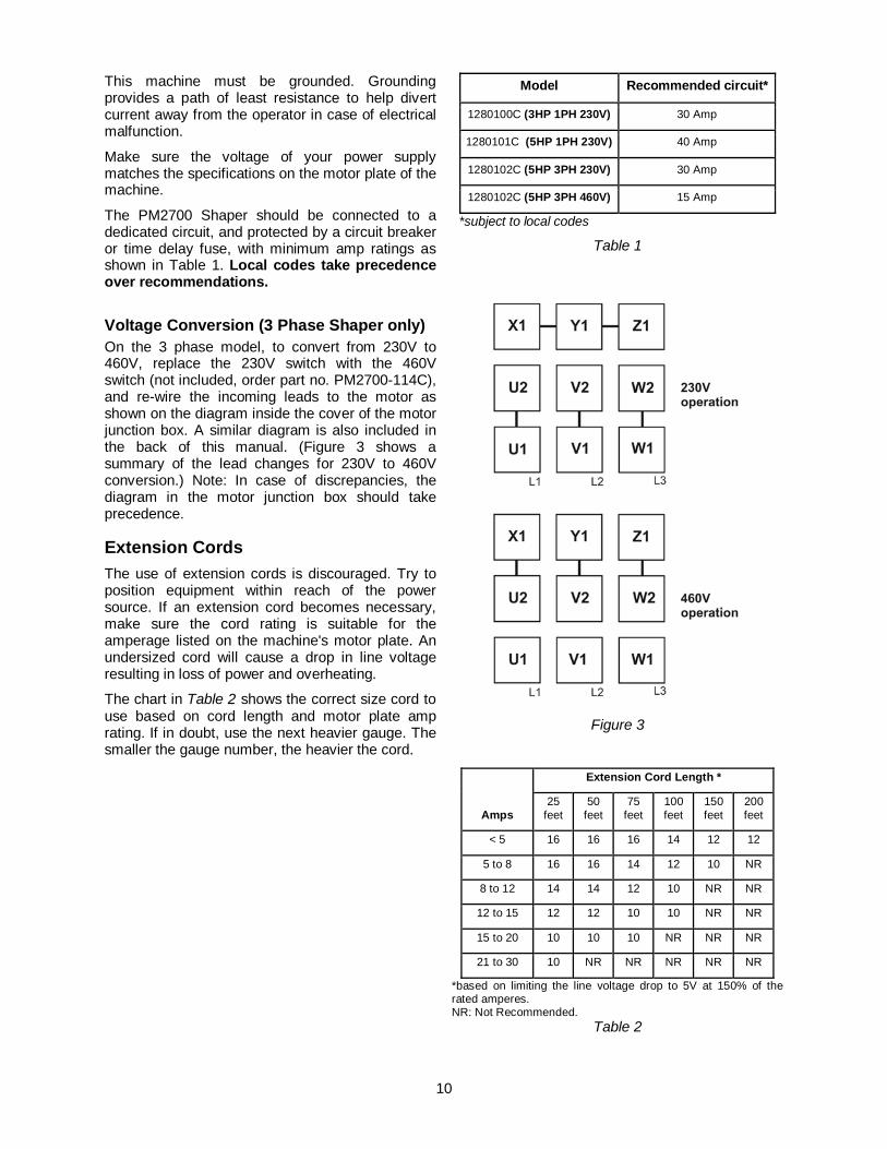
The PM2700 Shaper should be connected to a dedicated circuit, and protected by a circuit breaker or time delay fuse, with minimum amp ratings as shown in Table 1. Local codes take precedence over recommendations.
Voltage Conversion (3 Phase Shaper only) On the 3 phase model, to convert from 230V to 460V, replace the 230V switch with the 460V switch (not included, order part no. PM2700-114C), and re-wire the incoming leads to the motor as shown on the diagram inside the cover of the motor junction box. A similar diagram is also included in the back of this manual. (Figure 3 shows a summary of the lead changes for 230V to 460V conversion.) Note: In case of discrepancies, the diagram in the motor junction box should take precedence.
Extension Cords The use of extension cords is discouraged. Try to position equipment within reach of the power source. If an extension cord becomes necessary, make sure the cord rating is suitable for the amperage listed on the machine's motor plate. An undersized cord will cause a drop in line voltage resulting in loss of power and overheating.
The chart in Table 2 shows the correct size cord to use based on cord length and motor plate amp rating. If in doubt, use the next heavier gauge. The smaller the gauge number, the heavier the cord.
Model Recommended circuit*
1280100C (3HP 1PH 230V) 30 Amp
1280101C (5HP 1PH 230V) 40 Amp
1280102C (5HP 3PH 230V) 30 Amp
1280102C (5HP 3PH 460V) 15 Amp
*subject to local codes
Table 1
Figure 3
Amps
Extension Cord Length *
25 feet
50 feet
75 feet
100 feet
150 feet
200 feet
< 5 16 16 16 14 12 12
5 to 8 16 16 14 12 10 NR
8 to 12 14 14 12 10 NR NR
12 to 15 12 12 10 10 NR NR
15 to 20 10 10 10 NR NR NR
21 to 30 10 NR NR NR NR NR
*based on limiting the line voltage drop to 5V at 150% of the rated amperes. NR: Not Recommended.
Table 2
11
Adjustments When changing tools, making
adjustments, or doing clean-up and maintenance, always turn the machine off and unplug the machine from its power source.
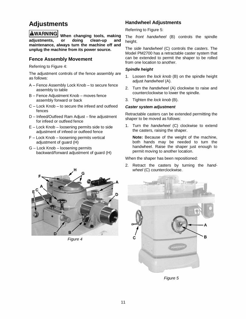
Fence Assembly Movement Referring to Figure 4:
The adjustment controls of the fence assembly are as follows:
A – Fence Assembly Lock Knob – to secure fence assembly to table
B – Fence Adjustment Knob – moves fence assembly forward or back
C – Lock Knob – to secure the infeed and outfeed fences
D – Infeed/Outfeed Ram Adjust – fine adjustment for infeed or outfeed fence
E – Lock Knob – loosening permits side to side adjustment of infeed or outfeed fence
F – Lock Knob – loosening permits vertical adjustment of guard (H)
G – Lock Knob – loosening permits backward/forward adjustment of guard (H)
Figure 4
Handwheel Adjustments Referring to Figure 5:
The front handwheel (B) controls the spindle height.
The side handwheel (C) controls the casters. The Model PM2700 has a retractable caster system that can be extended to permit the shaper to be rolled from one location to another.
Spindle height 1. Loosen the lock knob (B) on the spindle height
adjust handwheel (A).
2. Turn the handwheel (A) clockwise to raise and counterclockwise to lower the spindle.
3. Tighten the lock knob (B).
Caster system adjustment
Retractable casters can be extended permitting the shaper to be moved as follows:
1. Turn the handwheel (C) clockwise to extend the casters, raising the shaper.
Note: Because of the weight of the machine, both hands may be needed to turn the handwheel. Raise the shaper just enough to permit moving to another location.
When the shaper has been repositioned:
2. Retract the casters by turning the hand-wheel (C) counterclockwise.
Figure 5
12
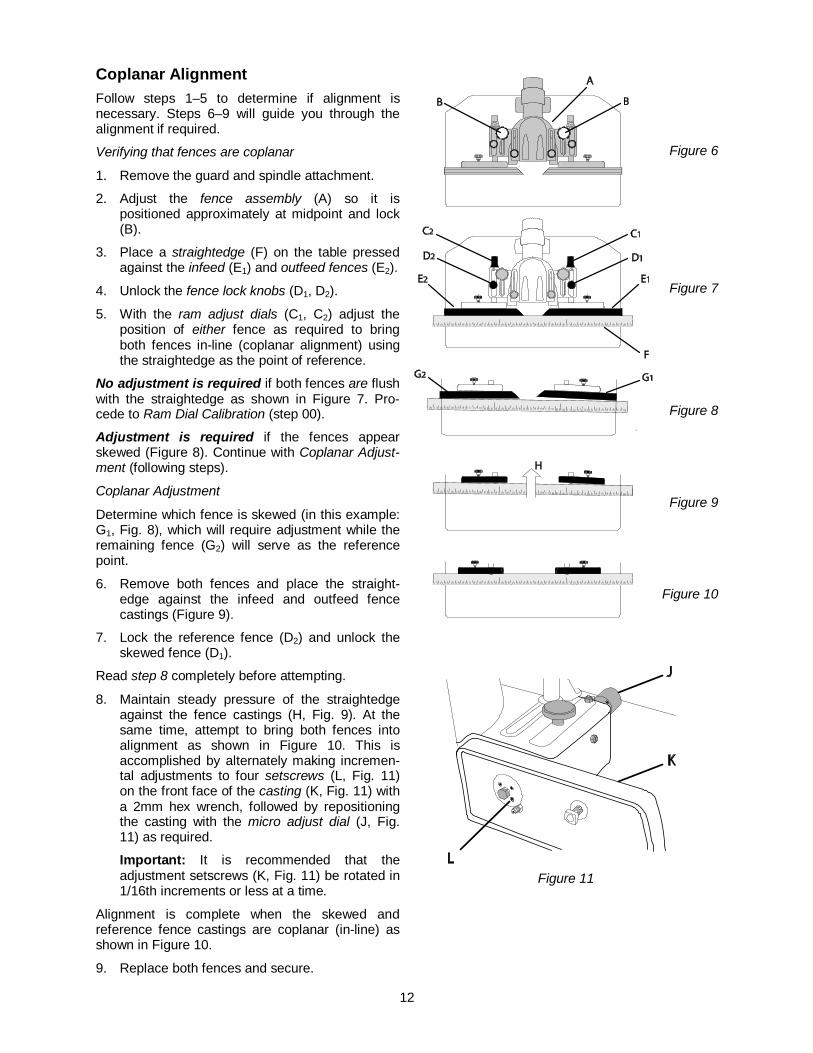
Coplanar Alignment Follow steps 1–5 to determine if alignment is necessary. Steps 6–9 will guide you through the alignment if required.
Verifying that fences are coplanar
1. Remove the guard and spindle attachment.
2. Adjust the fence assembly (A) so it is positioned approximately at midpoint and lock (B).
3. Place a straightedge (F) on the table pressed against the infeed (E1) and outfeed fences (E2).
4. Unlock the fence lock knobs (D1, D2).
5. With the ram adjust dials (C1, C2) adjust the position of either fence as required to bring both fences in-line (coplanar alignment) using the straightedge as the point of reference.
No adjustment is required if both fences are flush with the straightedge as shown in Figure 7. Pro-cede to Ram Dial Calibration (step 00).
Adjustment is required if the fences appear skewed (Figure 8). Continue with Coplanar Adjust-ment (following steps).
Coplanar Adjustment
Determine which fence is skewed (in this example: G1, Fig. 8), which will require adjustment while the remaining fence (G2) will serve as the reference point.
6. Remove both fences and place the straight-edge against the infeed and outfeed fence castings (Figure 9).
7. Lock the reference fence (D2) and unlock the skewed fence (D1).
Read step 8 completely before attempting.
8. Maintain steady pressure of the straightedge against the fence castings (H, Fig. 9). At the same time, attempt to bring both fences into alignment as shown in Figure 10. This is accomplished by alternately making incremen-tal adjustments to four setscrews (L, Fig. 11) on the front face of the casting (K, Fig. 11) with a 2mm hex wrench, followed by repositioning the casting with the micro adjust dial (J, Fig. 11) as required.
Important: It is recommended that the adjustment setscrews (K, Fig. 11) be rotated in 1/16th increments or less at a time.
Alignment is complete when the skewed and reference fence castings are coplanar (in-line) as shown in Figure 10.
9. Replace both fences and secure.
Figure 6
Figure 7
Figure 8
Figure 9
Figure 10
Figure 11
13
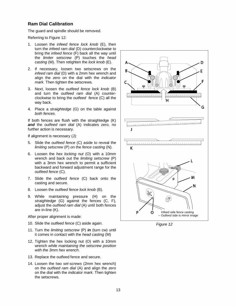
Ram Dial Calibration The guard and spindle should be removed.
Referring to Figure 12:
1. Loosen the infeed fence lock knob (E), then turn the infeed ram dial (D) counterclockwise to bring the infeed fence (F) back all the way until the limiter setscrew (P) touches the head casting (M). Then retighten the lock knob (E).
2. If necessary, loosen two setscrews on the infeed ram dial (D) with a 2mm hex wrench and align the zero on the dial with the indicator mark. Then tighten the setscrews.
3. Next, loosen the outfeed fence lock knob (B) and turn the outfeed ram dial (A) counter-clockwise to bring the outfeed fence (C) all the way back.
4. Place a straightedge (G) on the table against both fences.
If both fences are flush with the straightedge (K) and the outfeed ram dial (A) indicates zero, no further action is necessary.
If alignment is necessary (J):
5. Slide the outfeed fence (C) aside to reveal the limiting setscrew (P) on the fence casting (N).
6. Loosen the hex locking nut (O) with a 10mm wrench and back out the limiting setscrew (P) with a 3mm hex wrench to permit a sufficient backward and forward adjustment range for the outfeed fence (C).
7. Slide the outfeed fence (C) back onto the casting and secure.
8. Loosen the outfeed fence lock knob (B).
9. While maintaining pressure (H) on the straightedge (G) against the fences (C, F), adjust the outfeed ram dial (A) until both fences are in-line (K).
After proper alignment is made:
10. Slide the outfeed fence (C) aside again.
11. Turn the limiting setscrew (P) in (turn cw) until it comes in contact with the head casting (M)
12. Tighten the hex locking nut (O) with a 10mm wrench while maintaining the setscrew position with the 3mm hex wrench.
13. Replace the outfeed fence and secure.
14. Loosen the two set-screws (2mm hex wrench) on the outfeed ram dial (A) and align the zero on the dial with the indicator mark. Then tighten the setscrews.
-- Outfeed side is mirror imageInfeed side fence casting
Figure 12
14
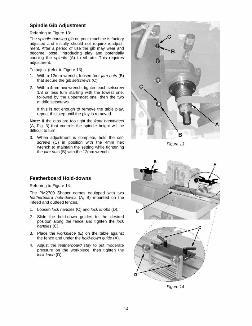
Spindle Gib Adjustment Referring to Figure 13: The spindle housing gib on your machine is factory adjusted and initially should not require readjust-ment. After a period of use the gib may wear and become loose, introducing play and potentially causing the spindle (A) to vibrate. This requires adjustment.
To adjust (refer to Figure 13): 1. With a 12mm wrench, loosen four jam nuts (B)
that secure the gib setscrews (C).
2. With a 4mm hex wrench, tighten each setscrew 1/8 or less turn starting with the lowest one, followed by the uppermost one, then the two middle setscrews.
If this is not enough to remove the table play, repeat this step until the play is removed.
Note: If the gibs are too tight the front handwheel (A, Fig. 3) that controls the spindle height will be difficult to turn.
3. When adjustment is complete, hold the set-screws (C) in position with the 4mm hex wrench to maintain the setting while tightening the jam nuts (B) with the 12mm wrench.
Featherboard Hold-downs Referring to Figure 14:
The PM2700 Shaper comes equipped with two featherboard hold-downs (A, B) mounted on the infeed and outfeed fences.
1. Loosen lock handles (C) and lock knobs (D).
2. Slide the hold-down guides to the desired position along the fence and tighten the lock handles (C).
3. Place the workpiece (E) on the table against the fence and under the hold-down guide (A).
4. Adjust the featherboard stay to put moderate pressure on the workpiece, then tighten the lock knob (D).
Figure 13
Figure 14
15
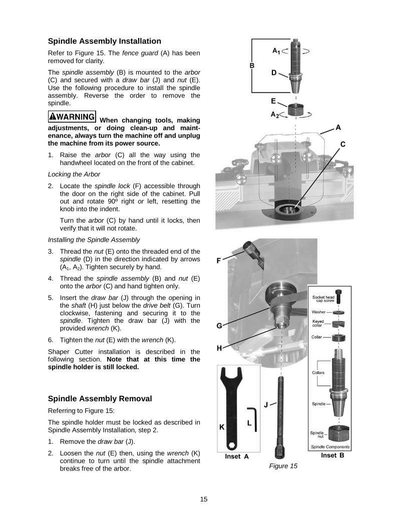
Spindle Assembly Installation Refer to Figure 15. The fence guard (A) has been removed for clarity.
The spindle assembly (B) is mounted to the arbor (C) and secured with a draw bar (J) and nut (E). Use the following procedure to install the spindle assembly. Reverse the order to remove the spindle.
When changing tools, making adjustments, or doing clean-up and maint-enance, always turn the machine off and unplug the machine from its power source. 1. Raise the arbor (C) all the way using the
handwheel located on the front of the cabinet.
Locking the Arbor
2. Locate the spindle lock (F) accessible through the door on the right side of the cabinet. Pull out and rotate 90º right or left, resetting the knob into the indent.
Turn the arbor (C) by hand until it locks, then verify that it will not rotate.
Installing the Spindle Assembly
3. Thread the nut (E) onto the threaded end of the spindle (D) in the direction indicated by arrows (A1, A2). Tighten securely by hand.
4. Thread the spindle assembly (B) and nut (E) onto the arbor (C) and hand tighten only.
5. Insert the draw bar (J) through the opening in the shaft (H) just below the drive belt (G). Turn clockwise, fastening and securing it to the spindle. Tighten the draw bar (J) with the provided wrench (K).
6. Tighten the nut (E) with the wrench (K).
Shaper Cutter installation is described in the following section. Note that at this time the spindle holder is still locked.
Spindle Assembly Removal Referring to Figure 15:
The spindle holder must be locked as described in Spindle Assembly Installation, step 2.
1. Remove the draw bar (J).
2. Loosen the nut (E) then, using the wrench (K) continue to turn until the spindle attachment breaks free of the arbor.
Figure 15
16
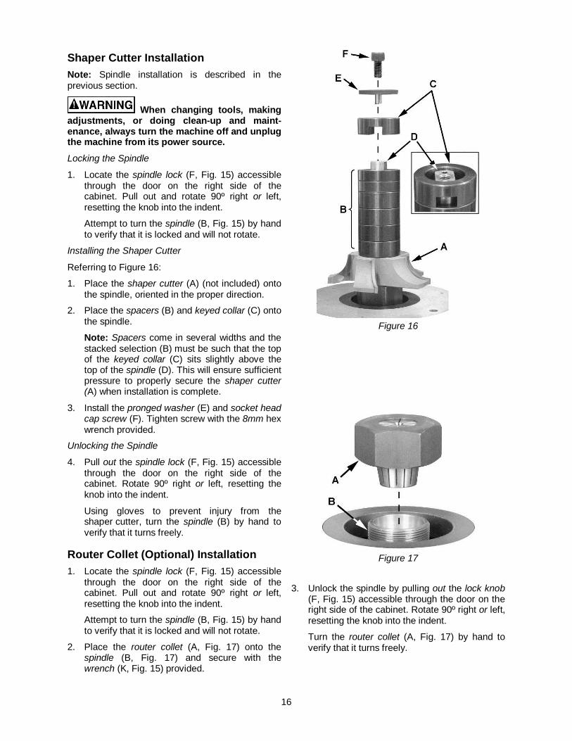
Shaper Cutter Installation Note: Spindle installation is described in the previous section.
When changing tools, making adjustments, or doing clean-up and maint-enance, always turn the machine off and unplug the machine from its power source. Locking the Spindle
1. Locate the spindle lock (F, Fig. 15) accessible through the door on the right side of the cabinet. Pull out and rotate 90º right or left, resetting the knob into the indent.
Attempt to turn the spindle (B, Fig. 15) by hand to verify that it is locked and will not rotate.
Installing the Shaper Cutter
Referring to Figure 16:
1. Place the shaper cutter (A) (not included) onto the spindle, oriented in the proper direction.
2. Place the spacers (B) and keyed collar (C) onto the spindle.
Note: Spacers come in several widths and the stacked selection (B) must be such that the top of the keyed collar (C) sits slightly above the top of the spindle (D). This will ensure sufficient pressure to properly secure the shaper cutter (A) when installation is complete.
3. Install the pronged washer (E) and socket head cap screw (F). Tighten screw with the 8mm hex wrench provided.
Unlocking the Spindle
4. Pull out the spindle lock (F, Fig. 15) accessible through the door on the right side of the cabinet. Rotate 90º right or left, resetting the knob into the indent.
Using gloves to prevent injury from the shaper cutter, turn the spindle (B) by hand to verify that it turns freely.
Router Collet (Optional) Installation 1. Locate the spindle lock (F, Fig. 15) accessible
through the door on the right side of the cabinet. Pull out and rotate 90º right or left, resetting the knob into the indent.
Attempt to turn the spindle (B, Fig. 15) by hand to verify that it is locked and will not rotate.
2. Place the router collet (A, Fig. 17) onto the spindle (B, Fig. 17) and secure with the wrench (K, Fig. 15) provided.
Figure 16
Figure 17
3. Unlock the spindle by pulling out the lock knob
(F, Fig. 15) accessible through the door on the right side of the cabinet. Rotate 90º right or left, resetting the knob into the indent.
Turn the router collet (A, Fig. 17) by hand to verify that it turns freely.
17
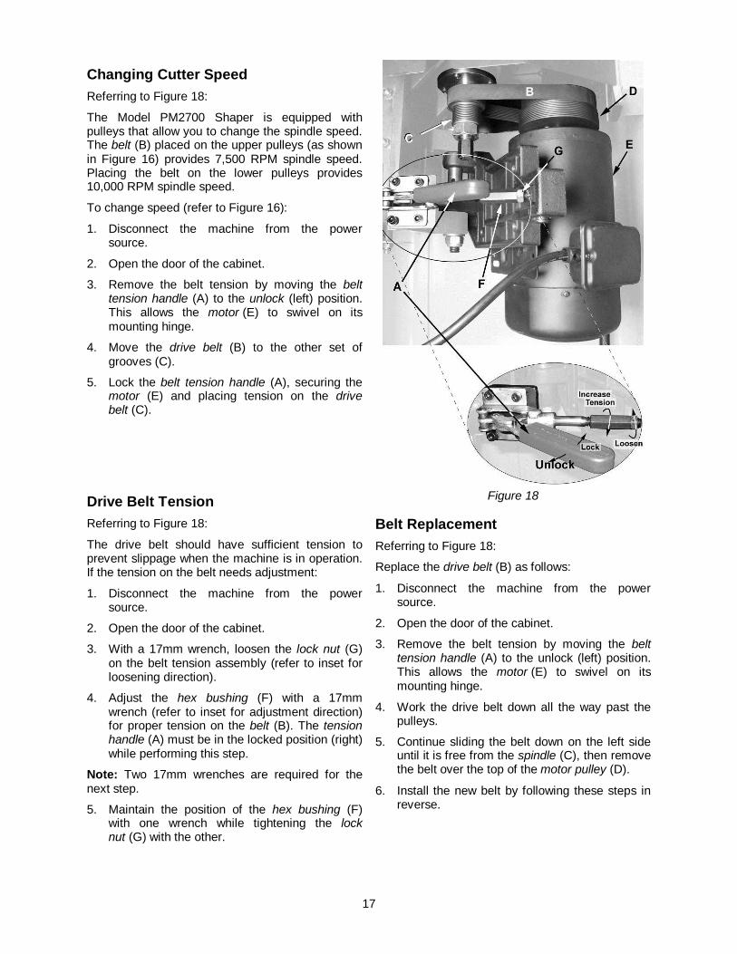
Changing Cutter Speed Referring to Figure 18:
The Model PM2700 Shaper is equipped with pulleys that allow you to change the spindle speed. The belt (B) placed on the upper pulleys (as shown in Figure 16) provides 7,500 RPM spindle speed. Placing the belt on the lower pulleys provides 10,000 RPM spindle speed.
To change speed (refer to Figure 16):
1. Disconnect the machine from the power source.
2. Open the door of the cabinet.
3. Remove the belt tension by moving the belt tension handle (A) to the unlock (left) position. This allows the motor (E) to swivel on its mounting hinge.
4. Move the drive belt (B) to the other set of grooves (C).
5. Lock the belt tension handle (A), securing the motor (E) and placing tension on the drive belt (C).
Drive Belt Tension Referring to Figure 18:
The drive belt should have sufficient tension to prevent slippage when the machine is in operation. If the tension on the belt needs adjustment:
1. Disconnect the machine from the power source.
2. Open the door of the cabinet.
3. With a 17mm wrench, loosen the lock nut (G) on the belt tension assembly (refer to inset for loosening direction).
4. Adjust the hex bushing (F) with a 17mm wrench (refer to inset for adjustment direction) for proper tension on the belt (B). The tension handle (A) must be in the locked position (right) while performing this step.
Note: Two 17mm wrenches are required for the next step.
5. Maintain the position of the hex bushing (F) with one wrench while tightening the lock nut (G) with the other.
Figure 18
Belt Replacement Referring to Figure 18:
Replace the drive belt (B) as follows:
1. Disconnect the machine from the power source.
2. Open the door of the cabinet.
3. Remove the belt tension by moving the belt tension handle (A) to the unlock (left) position. This allows the motor (E) to swivel on its mounting hinge.
4. Work the drive belt down all the way past the pulleys.
5. Continue sliding the belt down on the left side until it is free from the spindle (C), then remove the belt over the top of the motor pulley (D).
6. Install the new belt by following these steps in reverse.
18
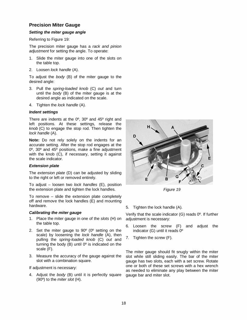
Precision Miter Gauge Setting the miter gauge angle
Referring to Figure 19:
The precision miter gauge has a rack and pinion adjustment for setting the angle. To operate:
1. Slide the miter gauge into one of the slots on the table top.
2. Loosen lock handle (A).
To adjust the body (B) of the miter gauge to the desired angle:
3. Pull the spring-loaded knob (C) out and turn until the body (B) of the miter gauge is at the desired angle as indicated on the scale.
4. Tighten the lock handle (A).
Indent settings
There are indents at the 0º, 30º and 45º right and left positions. At these settings, release the knob (C) to engage the stop rod. Then tighten the lock handle (A).
Note: Do not rely solely on the indents for an accurate setting. After the stop rod engages at the 0º, 30º and 45º positions, make a fine adjustment with the knob (C), if necessary, setting it against the scale indicator.
Extension plate The extension plate (D) can be adjusted by sliding to the right or left or removed entirely.
To adjust – loosen two lock handles (E), position the extension plate and tighten the lock handles.
To remove – slide the extension plate completely off and remove the lock handles (E) and mounting hardware.
Calibrating the miter gauge 1. Place the miter gauge in one of the slots (H) on
the table top.
2. Set the miter gauge to 90º (0º setting on the scale) by loosening the lock handle (A), then pulling the spring-loaded knob (C) out and turning the body (B) until 0º is indicated on the scale (F).
3. Measure the accuracy of the gauge against the slot with a combination square.
If adjustment is necessary:
4. Adjust the body (B) until it is perfectly square (90º) to the miter slot (H).
Figure 19
5. Tighten the lock handle (A).
Verify that the scale indicator (G) reads 0º. If further adjustment is necessary:
6. Loosen the screw (F) and adjust the indicator (G) until it reads 0º
7. Tighten the screw (F).
The miter gauge should fit snugly within the miter slot while still sliding easily. The bar of the miter gauge has two slots, each with a set screw. Rotate one or both of these set screws with a hex wrench as needed to eliminate any play between the miter gauge bar and miter slot.

19
Operating Controls Start/Stop Power Indicator Light – The start switch has a power indicator lamp which is on whenever there is power connected to the shaper, not just when the shaper is running. Do not assume that no light means there is no power to the machine. If the bulb is bad, there will be no indication. Always check before use.
Do not rely that no light means no power to the machine. Always check for power first. Failure to comply may cause serious injury!
Referring to Figure 20:
Start – Press the green start switch (see Note).
When power is connected to the machine, the green light is always on regardless of whether the shaper is running or not.
Note: In addition, the switch on the digital readout must be set to forward (or reverse) and the cabinet door must be closed.
Stop – Press the red switch to stop.
Reset – In the event that the shaper stops without pressing the stop button, as the result of a tripped fuse or circuit breaker, etc.:
1. Press red button to reset
2. Press the green button to restart the machine.
Figure 20
Safety Key The start/stop switch on the Model PM2700 comes equipped with a magnetic safety key. When in place on the switch as shown in Figure 20 the magnetic safety key trips a relay which will allow the machine to start and stop when the respective switches are pressed. Being
magnetic, the lock can be removed to make the machine inoperable and can be hidden for safe storage by attaching it underneath the rail or another magnetic surface.
When using the shaper, place the key on the switch cover lining up the arrow on the key with the REMOVE arrow on the cover. Then rotate the key so the arrow lines up with the LOCK arrow. This will prevent the safety key from coming loose from vibration when the machine is in use.
Digital Readout The digital readout (Figure 21) is used for making incremental spindle height adjustments where applicable, if multiple shaping/cutting passes are to be performed on a given work-piece.
Set the digital readout as follows:
1. Set the desired spindle height for the workpiece to be cut.
2. Supply power to the machine so the digital display is lit.
3. Select inch or mm by momentarily depressing the button on the right.
4. Press the 0" SET button for approximately two seconds.
The digital display resets to zero, which is your reference point. When the spindle is raised or lowered (front handwheel), the change is relative to this reference.
If this feature is used, the display should be reset to zero for each new cutting operation.
Figure 21
20
Operations Overview Before applying power to the machine, Check the motor and switch wiring diagrams for proper voltage connections. Check that all mounting screws and bolts are tight.
Turn on the motor momentarily to check for proper rotation. The spindle should rotate counterclock-wise when looking down on the spindle. Correct as required.
Run the machine for a short period of time to ensure that the moving parts are working properly with no excessive vibration. If a problem develops, correct it before turning the shaper over for general use.
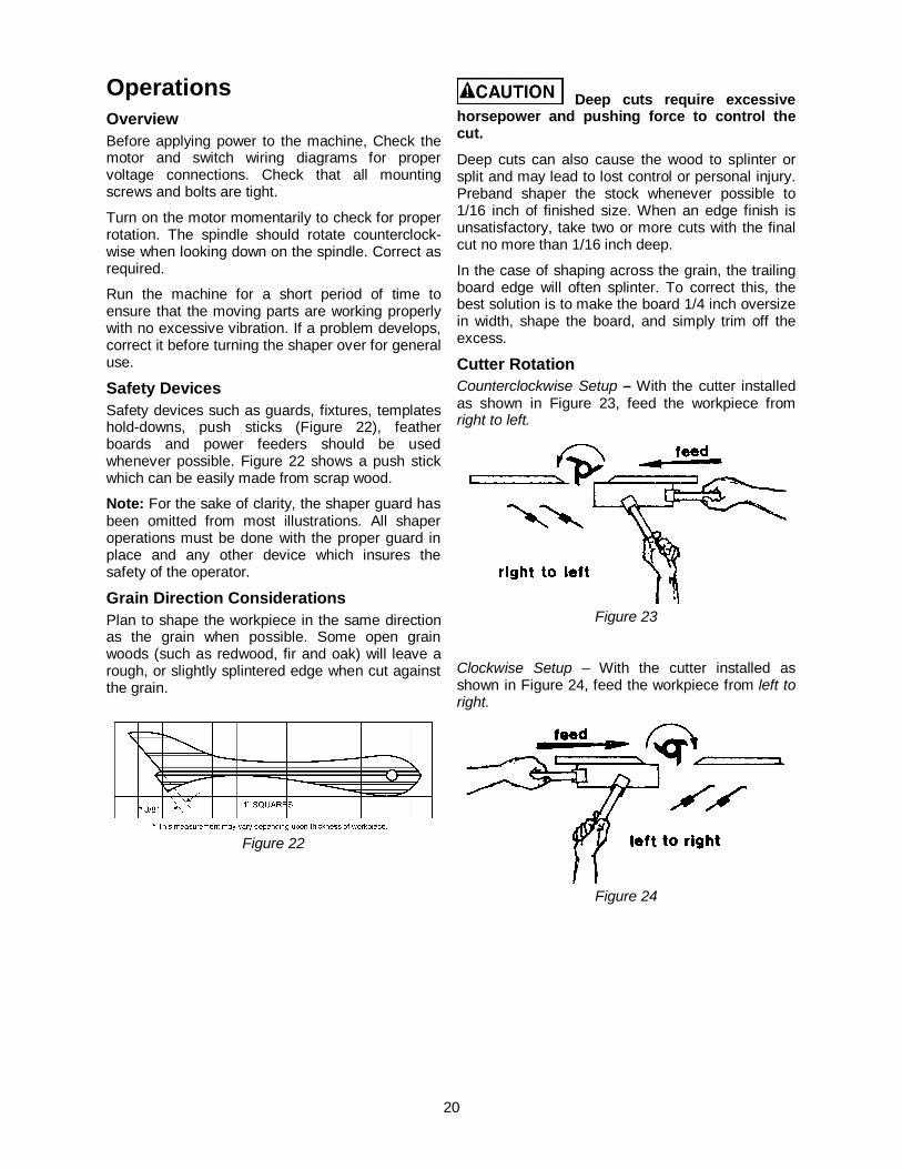
Safety Devices Safety devices such as guards, fixtures, templates hold-downs, push sticks (Figure 22), feather boards and power feeders should be used whenever possible. Figure 22 shows a push stick which can be easily made from scrap wood.
Note: For the sake of clarity, the shaper guard has been omitted from most illustrations. All shaper operations must be done with the proper guard in place and any other device which insures the safety of the operator.
Grain Direction Considerations Plan to shape the workpiece in the same direction as the grain when possible. Some open grain woods (such as redwood, fir and oak) will leave a rough, or slightly splintered edge when cut against the grain.
Figure 22
Deep cuts require excessive horsepower and pushing force to control the cut.
Deep cuts can also cause the wood to splinter or split and may lead to lost control or personal injury. Preband shaper the stock whenever possible to 1/16 inch of finished size. When an edge finish is unsatisfactory, take two or more cuts with the final cut no more than 1/16 inch deep.
In the case of shaping across the grain, the trailing board edge will often splinter. To correct this, the best solution is to make the board 1/4 inch oversize in width, shape the board, and simply trim off the excess.
Cutter Rotation Counterclockwise Setup – With the cutter installed as shown in Figure 23, feed the workpiece from right to left.
Figure 23
Clockwise Setup – With the cutter installed as shown in Figure 24, feed the workpiece from left to right.
Figure 24
21
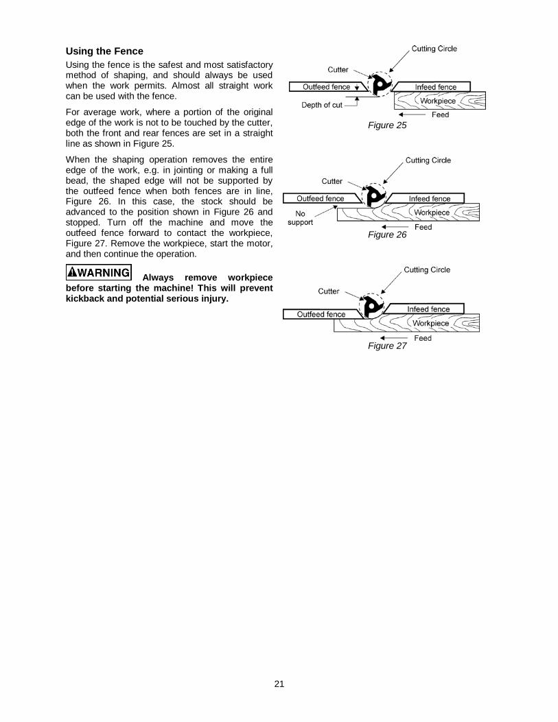
Using the Fence Using the fence is the safest and most satisfactory method of shaping, and should always be used when the work permits. Almost all straight work can be used with the fence.
For average work, where a portion of the original edge of the work is not to be touched by the cutter, both the front and rear fences are set in a straight line as shown in Figure 25.
When the shaping operation removes the entire edge of the work, e.g. in jointing or making a full bead, the shaped edge will not be supported by the outfeed fence when both fences are in line, Figure 26. In this case, the stock should be advanced to the position shown in Figure 26 and stopped. Turn off the machine and move the outfeed fence forward to contact the workpiece, Figure 27. Remove the workpiece, start the motor, and then continue the operation.
Always remove workpiece before starting the machine! This will prevent kickback and potential serious injury.
Figure 25
Figure 26
Figure 27
22
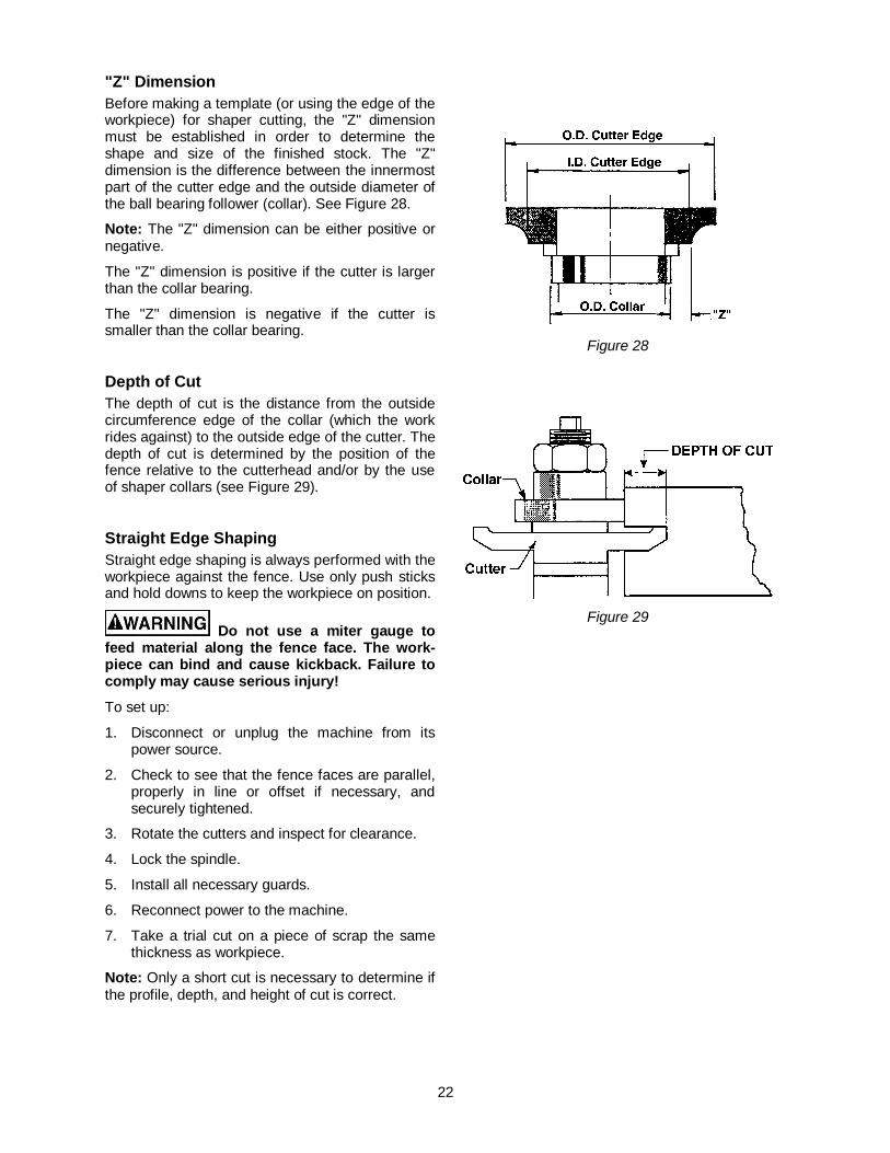
"Z" Dimension Before making a template (or using the edge of the workpiece) for shaper cutting, the "Z" dimension must be established in order to determine the shape and size of the finished stock. The "Z" dimension is the difference between the innermost part of the cutter edge and the outside diameter of the ball bearing follower (collar). See Figure 28.
Note: The "Z" dimension can be either positive or negative.
The "Z" dimension is positive if the cutter is larger than the collar bearing.
The "Z" dimension is negative if the cutter is smaller than the collar bearing.
Depth of Cut The depth of cut is the distance from the outside circumference edge of the collar (which the work rides against) to the outside edge of the cutter. The depth of cut is determined by the position of the fence relative to the cutterhead and/or by the use of shaper collars (see Figure 29).
Straight Edge Shaping Straight edge shaping is always performed with the workpiece against the fence. Use only push sticks and hold downs to keep the workpiece on position.
Do not use a miter gauge to feed material along the fence face. The work-piece can bind and cause kickback. Failure to comply may cause serious injury!
To set up:
1. Disconnect or unplug the machine from its power source.
2. Check to see that the fence faces are parallel, properly in line or offset if necessary, and securely tightened.
3. Rotate the cutters and inspect for clearance.
4. Lock the spindle.
5. Install all necessary guards.
6. Reconnect power to the machine.
7. Take a trial cut on a piece of scrap the same thickness as workpiece.
Note: Only a short cut is necessary to determine if the profile, depth, and height of cut is correct.
Figure 28
Figure 29
23
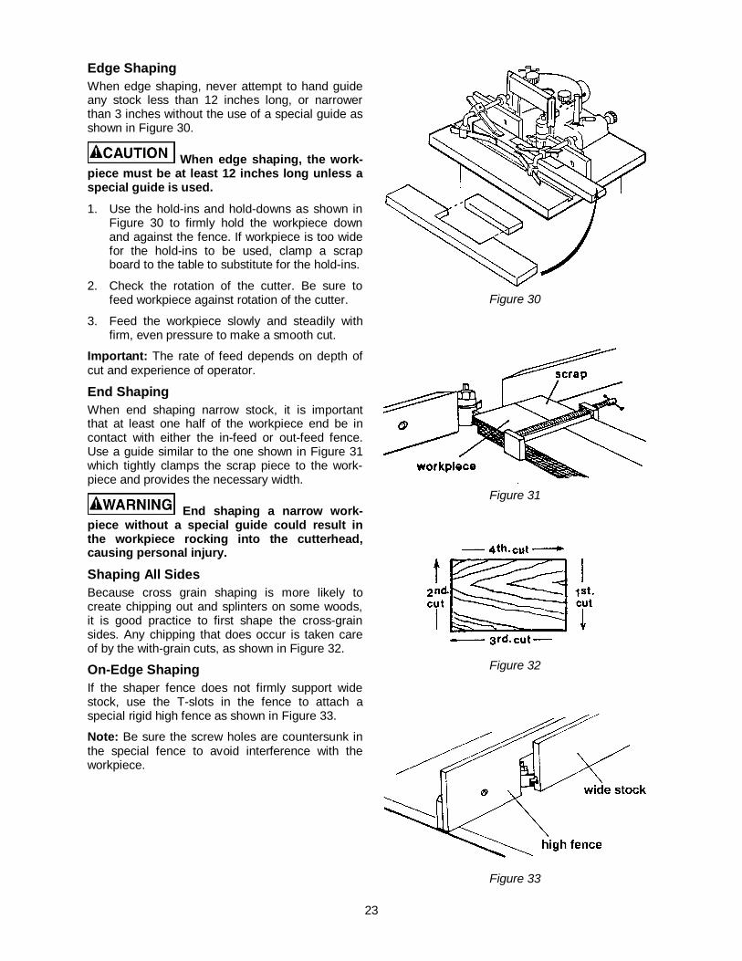
Edge Shaping When edge shaping, never attempt to hand guide any stock less than 12 inches long, or narrower than 3 inches without the use of a special guide as shown in Figure 30.
When edge shaping, the work-piece must be at least 12 inches long unless a special guide is used.
1. Use the hold-ins and hold-downs as shown in Figure 30 to firmly hold the workpiece down and against the fence. If workpiece is too wide for the hold-ins to be used, clamp a scrap board to the table to substitute for the hold-ins.
2. Check the rotation of the cutter. Be sure to feed workpiece against rotation of the cutter.
3. Feed the workpiece slowly and steadily with firm, even pressure to make a smooth cut.
Important: The rate of feed depends on depth of cut and experience of operator.
End Shaping When end shaping narrow stock, it is important that at least one half of the workpiece end be in contact with either the in-feed or out-feed fence. Use a guide similar to the one shown in Figure 31 which tightly clamps the scrap piece to the work-piece and provides the necessary width.
End shaping a narrow work-piece without a special guide could result in the workpiece rocking into the cutterhead, causing personal injury.
Shaping All Sides Because cross grain shaping is more likely to create chipping out and splinters on some woods, it is good practice to first shape the cross-grain sides. Any chipping that does occur is taken care of by the with-grain cuts, as shown in Figure 32.
On-Edge Shaping If the shaper fence does not firmly support wide stock, use the T-slots in the fence to attach a special rigid high fence as shown in Figure 33.
Note: Be sure the screw holes are countersunk in the special fence to avoid interference with the workpiece.
Figure 30
Figure 31
Figure 32
Figure 33
24
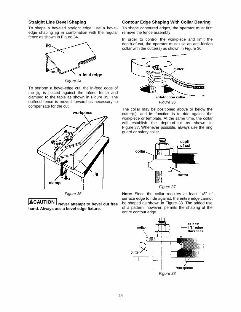
Straight Line Bevel Shaping To shape a beveled straight edge, use a bevel-edge shaping jig in combination with the regular fence as shown in Figure 34.
Figure 34
To perform a bevel-edge cut, the in-feed edge of the jig is placed against the infeed fence and clamped to the table as shown in Figure 35. The outfeed fence is moved forward as necessary to compensate for the cut.
Figure 35
Never attempt to bevel cut free hand. Always use a bevel-edge fixture.
Contour Edge Shaping With Collar BearingTo shape contoured edges, the operator must first remove the fence assembly.
In order to control the workpiece and limit the depth-of-cut, the operator must use an anti-friction collar with the cutter(s) as shown in Figure 36.
Figure 36
The collar may be positioned above or below the cutter(s), and its function is to ride against the workpiece or template. At the same time, the collar will establish the depth-of-cut as shown in Figure 37. Whenever possible, always use the ring guard or safety collar.
Figure 37
Note: Since the collar requires at least 1/8" of surface edge to ride against, the entire edge cannot be shaped as shown in Figure 38. The added use of a pattern, however, permits the shaping of the entire contour edge.
Figure 38
25
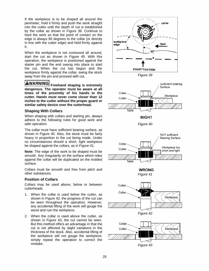
If the workpiece is to be shaped all around the perimeter, hold it firmly and push the work straight into the cutter until the depth of cut is established by the collar as shown in Figure 39. Continue to feed the work so that the point of contact on the edge is always 90 degrees to the collar (or directly in line with the cutter edge) and held firmly against it.
When the workpiece is not contoured all around, start the cut as shown in Figure 45. With this operation, the workpiece is positioned against the starter pin and the end swung into place to start the cut. When the cut has begun and the workpiece firmly against the collar, swing the stock away from the pin and proceed with cut.
Freehand shaping is extremely dangerous. The operator must be aware at all times of the proximity of his hands to the cutter. Hands must never come closer than 12 inches to the cutter without the proper guard or similar safety device over the cutterhead.
Shaping With Collars When shaping with collars and starting pin, always adhere to the following rules for good work and safe operation:
The collar must have sufficient bearing surface, as shown in Figure 40. Also, the stock must be fairly heavy in proportion to the cut being made. Under no circumstances should a short, light workpiece be shaped against the collars, as in Figure 41.
Note: The edge of the work to be shaped must be smooth. Any irregularity on the surface which rides against the collar will be duplicated on the molded surface.
Collars must be smooth and free from pitch and other substances.
Position of Collars Collars may be used above, below or between cutterheads.
1. When the collar is used below the cutter, as shown in Figure 42, the progress of the cut can be seen throughout the operation. However, any accidental lifting of the work will gouge the wood and ruin the workpiece.
2. When the collar is used above the cutter, as shown in Figure 43, the cut cannot be seen. But this method offers an advantage in that the cut is not affected by slight variations in the thickness of the stock. Also, accidental lifting of the workpiece will not gouge the workpiece; simply repeat the operation to correct the mistake.
Figure 39
Figure 40
Figure 41
Figure 42
Figure 43
26
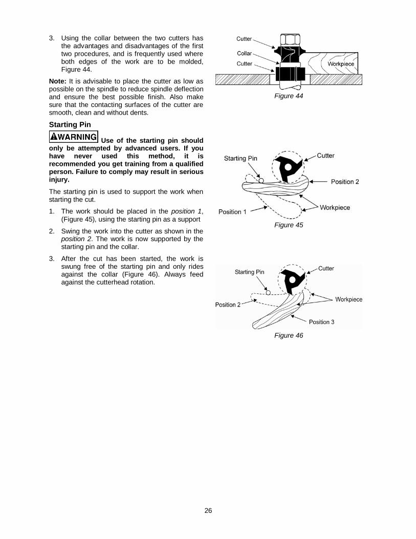
3. Using the collar between the two cutters has the advantages and disadvantages of the first two procedures, and is frequently used where both edges of the work are to be molded, Figure 44.
Note: It is advisable to place the cutter as low as possible on the spindle to reduce spindle deflection and ensure the best possible finish. Also make sure that the contacting surfaces of the cutter are smooth, clean and without dents.
Starting Pin
Use of the starting pin should only be attempted by advanced users. If you have never used this method, it is recommended you get training from a qualified person. Failure to comply may result in serious injury.
The starting pin is used to support the work when starting the cut.
1. The work should be placed in the position 1, (Figure 45), using the starting pin as a support
2. Swing the work into the cutter as shown in the position 2. The work is now supported by the starting pin and the collar.
3. After the cut has been started, the work is swung free of the starting pin and only rides against the collar (Figure 46). Always feed against the cutterhead rotation.
Figure 44
Figure 45
Figure 46
27
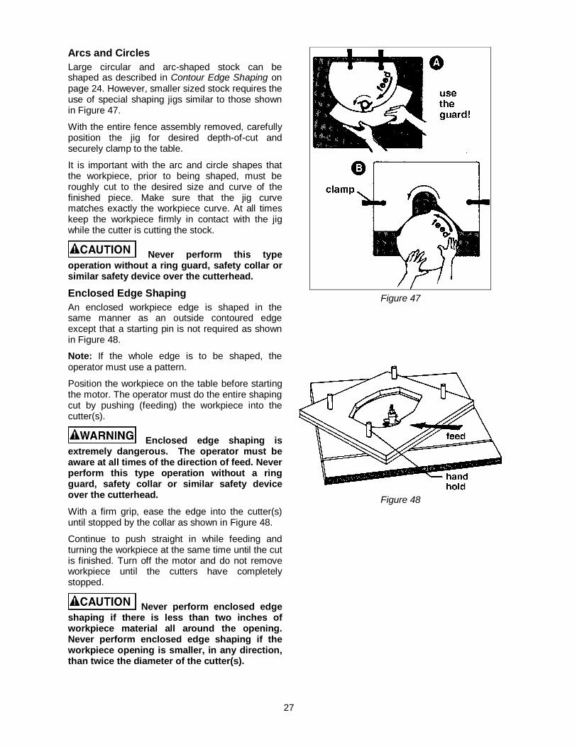
Arcs and Circles Large circular and arc-shaped stock can be shaped as described in Contour Edge Shaping on page 24. However, smaller sized stock requires the use of special shaping jigs similar to those shown in Figure 47.
With the entire fence assembly removed, carefully position the jig for desired depth-of-cut and securely clamp to the table.
It is important with the arc and circle shapes that the workpiece, prior to being shaped, must be roughly cut to the desired size and curve of the finished piece. Make sure that the jig curve matches exactly the workpiece curve. At all times keep the workpiece firmly in contact with the jig while the cutter is cutting the stock.
Never perform this type operation without a ring guard, safety collar or similar safety device over the cutterhead.
Enclosed Edge Shaping An enclosed workpiece edge is shaped in the same manner as an outside contoured edge except that a starting pin is not required as shown in Figure 48.
Note: If the whole edge is to be shaped, the operator must use a pattern.
Position the workpiece on the table before starting the motor. The operator must do the entire shaping cut by pushing (feeding) the workpiece into the cutter(s).
Enclosed edge shaping is extremely dangerous. The operator must be aware at all times of the direction of feed. Never perform this type operation without a ring guard, safety collar or similar safety device over the cutterhead.
With a firm grip, ease the edge into the cutter(s) until stopped by the collar as shown in Figure 48.
Continue to push straight in while feeding and turning the workpiece at the same time until the cut is finished. Turn off the motor and do not remove workpiece until the cutters have completely stopped.
Never perform enclosed edge shaping if there is less than two inches of workpiece material all around the opening. Never perform enclosed edge shaping if the workpiece opening is smaller, in any direction, than twice the diameter of the cutter(s).
Figure 47
Figure 48
28
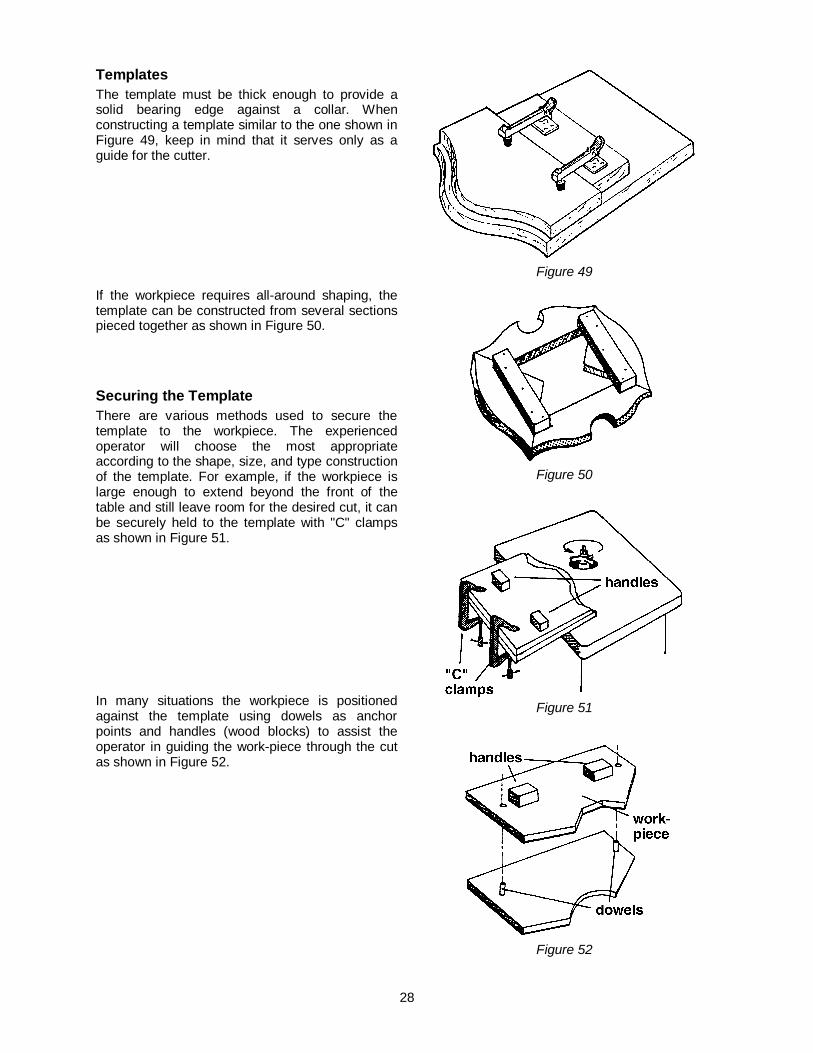
Templates The template must be thick enough to provide a solid bearing edge against a collar. When constructing a template similar to the one shown in Figure 49, keep in mind that it serves only as a guide for the cutter.
If the workpiece requires all-around shaping, the template can be constructed from several sections pieced together as shown in Figure 50.
Securing the Template There are various methods used to secure the template to the workpiece. The experienced operator will choose the most appropriate according to the shape, size, and type construction of the template. For example, if the workpiece is large enough to extend beyond the front of the table and still leave room for the desired cut, it can be securely held to the template with "C" clamps as shown in Figure 51.
In many situations the workpiece is positioned against the template using dowels as anchor points and handles (wood blocks) to assist the operator in guiding the work-piece through the cut as shown in Figure 52.
Figure 49
Figure 50
Figure 51
Figure 52
29
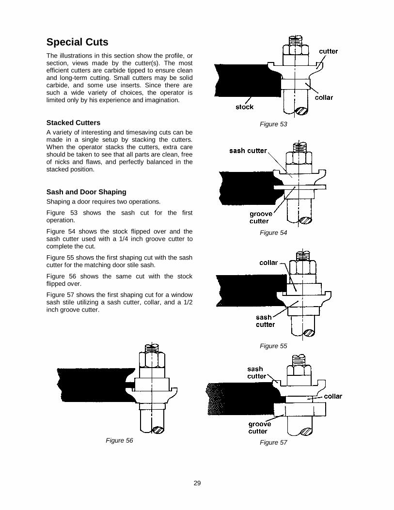
Special Cuts The illustrations in this section show the profile, or section, views made by the cutter(s). The most efficient cutters are carbide tipped to ensure clean and long-term cutting. Small cutters may be solid carbide, and some use inserts. Since there are such a wide variety of choices, the operator is limited only by his experience and imagination.
Stacked Cutters A variety of interesting and timesaving cuts can be made in a single setup by stacking the cutters. When the operator stacks the cutters, extra care should be taken to see that all parts are clean, free of nicks and flaws, and perfectly balanced in the stacked position.
Sash and Door Shaping Shaping a door requires two operations.
Figure 53 shows the sash cut for the first operation.
Figure 54 shows the stock flipped over and the sash cutter used with a 1/4 inch groove cutter to complete the cut.
Figure 55 shows the first shaping cut with the sash cutter for the matching door stile sash.
Figure 56 shows the same cut with the stock flipped over.
Figure 57 shows the first shaping cut for a window sash stile utilizing a sash cutter, collar, and a 1/2 inch groove cutter.
Figure 56
Figure 53
Figure 54
Figure 55
Figure 57
30
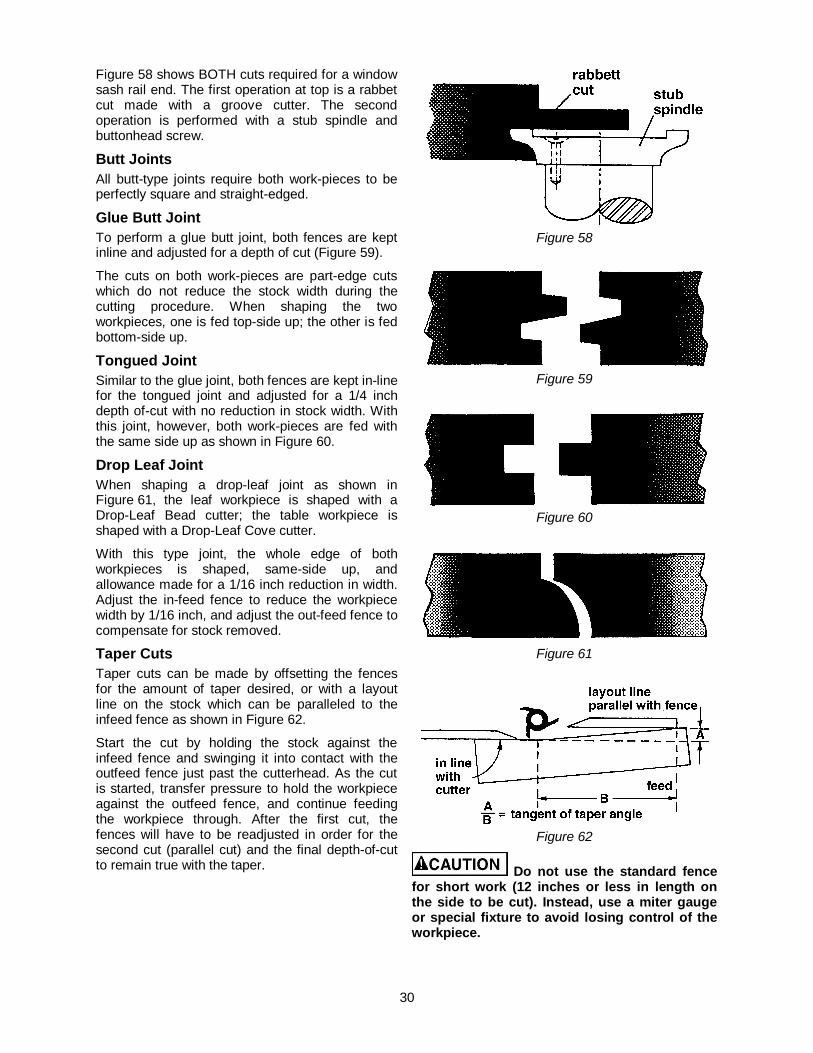
Figure 58 shows BOTH cuts required for a window sash rail end. The first operation at top is a rabbet cut made with a groove cutter. The second operation is performed with a stub spindle and buttonhead screw.
Butt Joints All butt-type joints require both work-pieces to be perfectly square and straight-edged.
Glue Butt Joint To perform a glue butt joint, both fences are kept inline and adjusted for a depth of cut (Figure 59).
The cuts on both work-pieces are part-edge cuts which do not reduce the stock width during the cutting procedure. When shaping the two workpieces, one is fed top-side up; the other is fed bottom-side up.
Tongued Joint Similar to the glue joint, both fences are kept in-line for the tongued joint and adjusted for a 1/4 inch depth of-cut with no reduction in stock width. With this joint, however, both work-pieces are fed with the same side up as shown in Figure 60.
Drop Leaf Joint When shaping a drop-leaf joint as shown in Figure 61, the leaf workpiece is shaped with a Drop-Leaf Bead cutter; the table workpiece is shaped with a Drop-Leaf Cove cutter.
With this type joint, the whole edge of both workpieces is shaped, same-side up, and allowance made for a 1/16 inch reduction in width. Adjust the in-feed fence to reduce the workpiece width by 1/16 inch, and adjust the out-feed fence to compensate for stock removed.
Taper Cuts Taper cuts can be made by offsetting the fences for the amount of taper desired, or with a layout line on the stock which can be paralleled to the infeed fence as shown in Figure 62.
Start the cut by holding the stock against the infeed fence and swinging it into contact with the outfeed fence just past the cutterhead. As the cut is started, transfer pressure to hold the workpiece against the outfeed fence, and continue feeding the workpiece through. After the first cut, the fences will have to be readjusted in order for the second cut (parallel cut) and the final depth-of-cut to remain true with the taper.
Figure 58
Figure 59
Figure 60
Figure 61
Figure 62
Do not use the standard fence for short work (12 inches or less in length on the side to be cut). Instead, use a miter gauge or special fixture to avoid losing control of the workpiece.
31
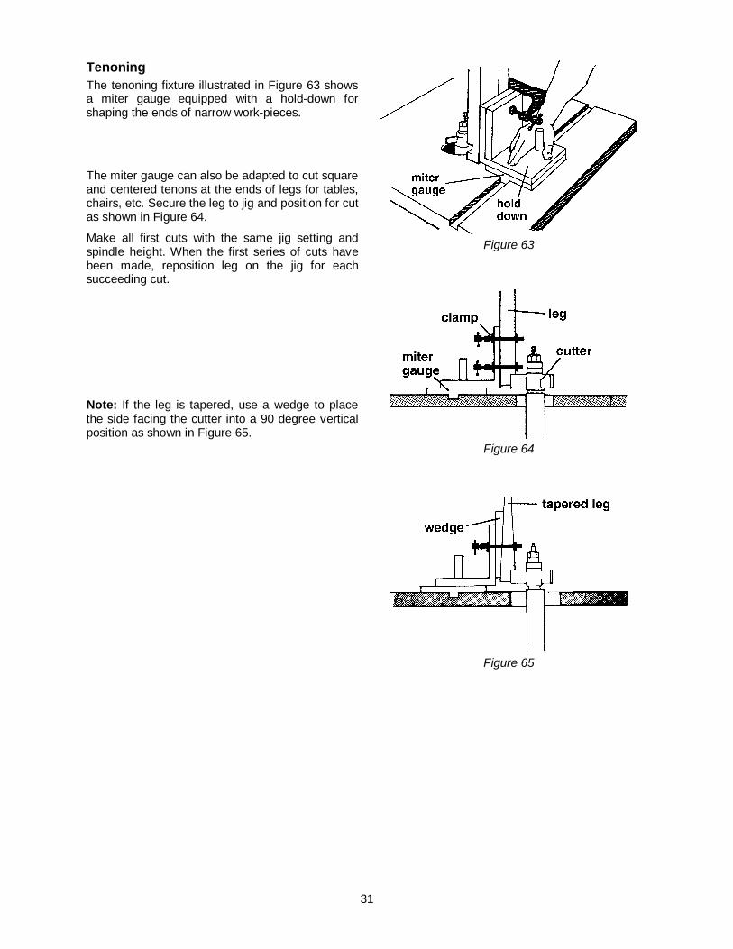
Tenoning The tenoning fixture illustrated in Figure 63 shows a miter gauge equipped with a hold-down for shaping the ends of narrow work-pieces.
The miter gauge can also be adapted to cut square and centered tenons at the ends of legs for tables, chairs, etc. Secure the leg to jig and position for cut as shown in Figure 64.
Make all first cuts with the same jig setting and spindle height. When the first series of cuts have been made, reposition leg on the jig for each succeeding cut.
Note: If the leg is tapered, use a wedge to place the side facing the cutter into a 90 degree vertical position as shown in Figure 65.
Figure 63
Figure 64
Figure 65

32
Troubleshooting for PM2700 Shaper Trouble Possible Cause Remedy
Shaper will not start. 1. Cord unplugged from the power source.
2. Fuse blown or circuited breaker tripped.
3. Cord damaged. 4. Reversing switch is in the Off
position. 5. Overload tripped.
6. Cabinet door is open.
1. Plug in power cord.
2. Replace fuse or reset circuit breaker.
3. Replace cord. 4. Turn switch to forward of reverse.
5. Reset overload by depressing red
stop button. 6. Close cabinet door.
Overload kicks out frequently.
1. Extension cord or wiring inadequate size.
2. Feeding stock too fast. 3. Cutter needs cleaning or replacing.
See also Unsatisfactory Cuts below.
1. Replace cord or wiring with proper gauge wire.
2. Reduce feed stock rate. 3. Clean or replace cutter.
Cuts are unsatisfactory.
1. Dull cutter. 2. Cutterhead rotating in wrong
direction. 3. Feeding work in wrong direction.
4. Gum or pitch on cutter.
5. Gum or pitch on table causing
erratic feed.
1. Replace cutter. 2. Check for proper rotation at startup.
3. Feed work against the cutter
rotation.
4. Remove cutter and clean with solvent.
5. Clean table with solvent.
Cutter does not come up to full speed.
1. Shop wire gauge is too small.
2. Extension cord or wiring inadequate size.
3. Power source is not adequate. 4. Motor not wired for correct voltage.
5. Spindle is locked with madrel lever.
1. Replace wiring with proper gauge wire.
2. Replace wit adequate size cord.
3. Contact your electric utility. 4. Refer to motor name place and
wiring diagram for correct wiring. 5. Unlock spindle – see label next to
lover on base.
Machine vibrates. 1. Stand on uneven surface.
2. Cutterhead damaged. 3. Defective V-belt. 4. V-belt incorrectly tensioned. 5. Bent pulley. 6. Motor mounted improperly.
1. Stand must rest solidly on level surface. Fasten to floor if necessary.
2. Replace cutterhead. 3. Replace V-belt. 4. Apply proper tension. 5. Replace pulley. 6. Motor must be properly mounted
with snug nuts and bolts.
Edge splits off on cross grain cut.
1. Characteristic of this type of cut. 1. Make cross grain cuts first, then finish cut with the grain. Use scrap block to support end of cut.

33
Trouble Possible Cause Remedy
Raised areas on shaped edge.
1. Variation of pressure holding work against cutter.
1. Hold work firmly against table and fence. Use hold-downs and push sticks.
Work pulled from hand.
1. Feeding in wrong direction. 1. Always feed work against the rotation of the cutterhead.
Depth of cut not uniform.
1. Fence misalignment. 2. Side pressure not uniform.
1. Align outfeed fence. 2. Use hold-downs; keep constant
pressure against fence and use push sticks.
Work burns. 1. Cutting too deep on one pass.
2. Forcing work.
1. On hardwoods take light cuts; attain full depth with several passes.
2. Feed work slowly and steadily.
Cut height not uniform.
1. Variation in pressure holding work to table.
1. Keep pressure uniform throughout pass. Use hold-downs. Make pass slowly and steadily. Keep work under cutter whenever possible.
Cuts not smooth. 1. Wrong R.P.M. 2. Feed too fast. 3. Working against the grain.
4. Cutting too deep on one pass.
1. Use faster speed. 2. Slow feed speed. 3. Work with the grain whenever
possible. 4. Take several passes on very deep
cuts.
Spindle does not raise freely.
1. Shaper dust and dirt in raising mechanism.
1. Brush or blow out loose dust and dirt.
Optional Accessories 1791205 1" Spindle 1791207 1/4" Collet 1791208 1/2" Collet
34
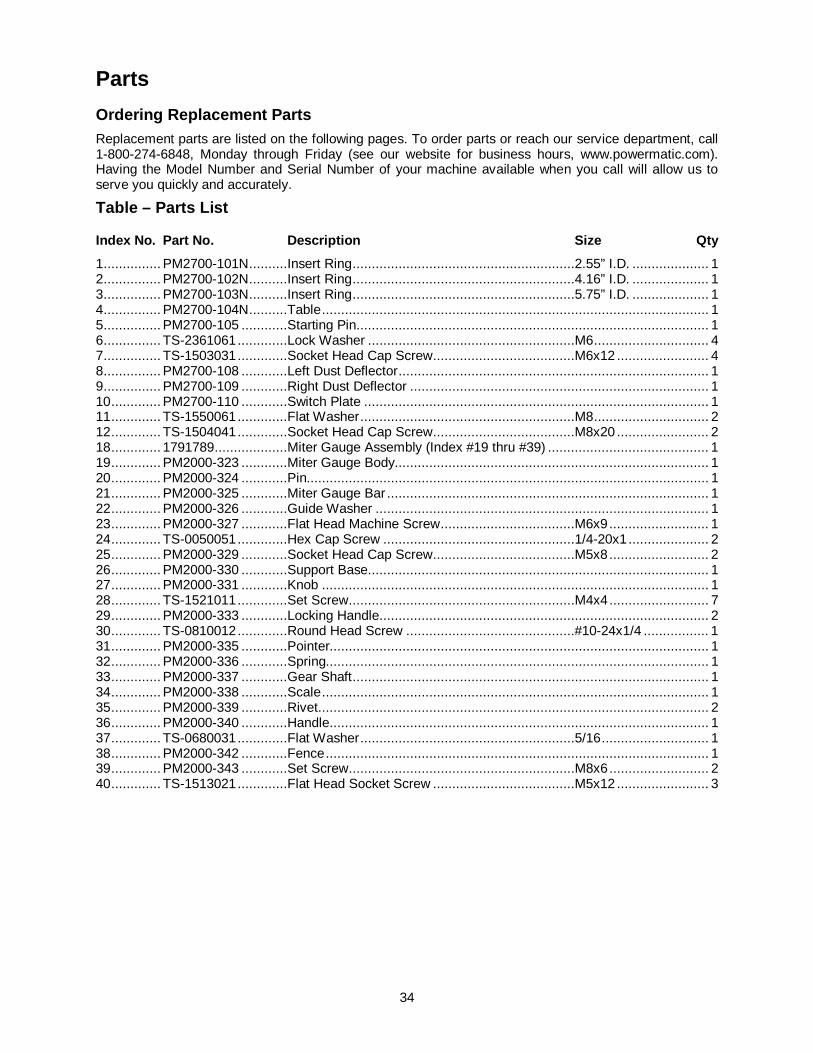
Parts Ordering Replacement Parts Replacement parts are listed on the following pages. To order parts or reach our service department, call 1-800-274-6848, Monday through Friday (see our website for business hours, www.powermatic.com). Having the Model Number and Serial Number of your machine available when you call will allow us to serve you quickly and accurately.
Table – Parts List
Index No. Part No. Description Size Qty 1 ............... PM2700-101N ..........Insert Ring ..........................................................2.55” I.D. .................... 1 2 ............... PM2700-102N ..........Insert Ring ..........................................................4.16” I.D. .................... 1 3 ............... PM2700-103N ..........Insert Ring ..........................................................5.75” I.D. .................... 1 4 ............... PM2700-104N ..........Table ..................................................................................................... 1 5 ............... PM2700-105 ............Starting Pin ............................................................................................ 1 6 ............... TS-2361061 .............Lock Washer ......................................................M6 .............................. 4 7 ............... TS-1503031 .............Socket Head Cap Screw .....................................M6x12 ........................ 4 8 ............... PM2700-108 ............Left Dust Deflector ................................................................................. 1 9 ............... PM2700-109 ............Right Dust Deflector .............................................................................. 1 10 ............. PM2700-110 ............Switch Plate .......................................................................................... 1 11 ............. TS-1550061 .............Flat Washer ........................................................M8 .............................. 2 12 ............. TS-1504041 .............Socket Head Cap Screw .....................................M8x20 ........................ 2 18 ............. 1791789...................Miter Gauge Assembly (Index #19 thru #39) .......................................... 1 19 ............. PM2000-323 ............Miter Gauge Body.................................................................................. 1 20 ............. PM2000-324 ............Pin......................................................................................................... 1 21 ............. PM2000-325 ............Miter Gauge Bar .................................................................................... 1 22 ............. PM2000-326 ............Guide Washer ....................................................................................... 1 23 ............. PM2000-327 ............Flat Head Machine Screw ...................................M6x9 .......................... 1 24 ............. TS-0050051 .............Hex Cap Screw ..................................................1/4-20x1 ..................... 2 25 ............. PM2000-329 ............Socket Head Cap Screw .....................................M5x8 .......................... 2 26 ............. PM2000-330 ............Support Base......................................................................................... 1 27 ............. PM2000-331 ............Knob ..................................................................................................... 1 28 ............. TS-1521011 .............Set Screw ...........................................................M4x4 .......................... 7 29 ............. PM2000-333 ............Locking Handle ...................................................................................... 2 30 ............. TS-0810012 .............Round Head Screw ............................................#10-24x1/4 ................. 1 31 ............. PM2000-335 ............Pointer................................................................................................... 1 32 ............. PM2000-336 ............Spring.................................................................................................... 1 33 ............. PM2000-337 ............Gear Shaft ............................................................................................. 1 34 ............. PM2000-338 ............Scale ..................................................................................................... 1 35 ............. PM2000-339 ............Rivet ...................................................................................................... 2 36 ............. PM2000-340 ............Handle................................................................................................... 1 37 ............. TS-0680031 .............Flat Washer ........................................................5/16 ............................ 1 38 ............. PM2000-342 ............Fence .................................................................................................... 1 39 ............. PM2000-343 ............Set Screw ...........................................................M8x6 .......................... 2 40 ............. TS-1513021 .............Flat Head Socket Screw .....................................M5x12 ........................ 3
35
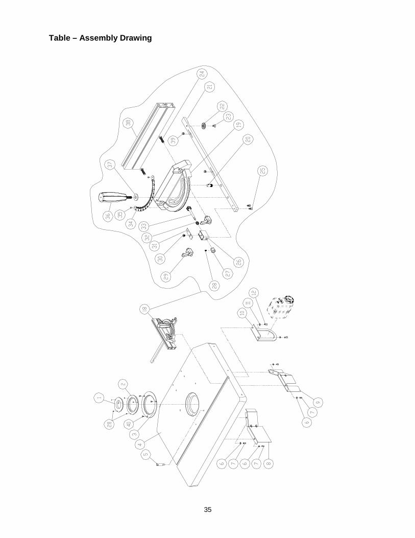
Table – Assembly Drawing

36
Fence – Parts List
Index No. Part No. Description Size Qty 1 ............... PM2700-201 ............Knob ..................................................................................................... 6 2 ............... PM2700-202 ............Guard Holder ......................................................................................... 1 3 ............... PM2700-203 ............Cutter Guard ......................................................................................... 1 4 ............... PM2700-204 ............Lock Knob ............................................................................................. 2 5 ............... PM2700-205 ............Flat Washer ........................................................M13 ............................ 2 6 ............... PM2700-206 ............Adjustment Knob ................................................................................... 2 7 ............... PM2700-207 ............Adjustment Lead Screw ......................................................................... 2 8 ............... TS-1523071 .............Socket Set Screw ...............................................M6x25 ........................ 6 9 ............... TS-2311061 .............Hex Nut ..............................................................M6 .............................. 6 10 ............. TS-1522011 .............Socket Set Screw ...............................................M5x6 .......................... 4 11 ............. PM2700-211 ............Column.................................................................................................. 1 12 ............. TS-1505031 .............Socket Head Cap Screw .....................................M10x25 ...................... 4 13 ............. TS-2361101 .............Lock Washer ......................................................M10 ............................ 4 14 ............. PM2700-214 ............Fence Column Bracket .......................................................................... 1 15 ............. TS-155010 ...............Flat Washer ........................................................M16 ........................... 1 16 ............. PM2700-216 ............Geared Knob ......................................................................................... 1 17 ............. PM2700-217 ............Spring Pin...........................................................Ø5x32 ........................ 1 18 ............. TS-2246202 .............Button Head Socket Screw .................................M6x20 ........................ 1 19 ............. TS-2361061 .............Lock Washer ......................................................M6 .............................. 1 20 ............. PM2700-220 ............Fence Body ........................................................................................... 1 21 ............. PM2700-221 ............Shaft ..................................................................................................... 2 22 ............. PM2700-222 ............Lock Knob ............................................................................................. 2 23 ............. PM2700-223 ............Washer.................................................................................................. 2 24 ............. PM2700-224 ............Left Fence Plate .................................................................................... 1 25 ............. PM2700-225 ............Square Nut .........................................................M8 .............................. 2 26 ............. PM2700-226 ............Right Fence Plate .................................................................................. 1 27 ............. TS-1523021 .............Socket Set Screw ...............................................M6x8 .......................... 8 28 ............. PM2700-228 ............Bushing ................................................................................................. 2 29 ............. TS-1490051 .............Hex Cap Screw ..................................................M8x30 ........................ 2 30 ............. PM2700-230 ............Fence .................................................................................................... 2 31 ............. PM2700-231 ............End Cap ................................................................................................ 2 32 ............. PM2700-232 ............Lock Handle .......................................................................................... 4 33 ............. TS-1550061 .............Flat Washer ........................................................M8 .............................. 4 34 ............. PM2700-234 ............Bracket .................................................................................................. 2 35 ............. PM2700-235 ............Carriage Bolt ......................................................M5x30 ........................ 4 36 ............. PM2700-236 ............Carriage Bolt ......................................................M5x16 ........................ 4 37 ............. PM2700-237 ............Feather Board ....................................................................................... 2 38 ............. PM2700-238 ............Knob ..................................................................................................... 4 ................. PM2700-FBA ...........Feather Board Assembly (index # 32 through 38) .................................. 1 ................. PM2700-FA..............Fence – Complete Assembly (index # 1 through 38) .............................. 1
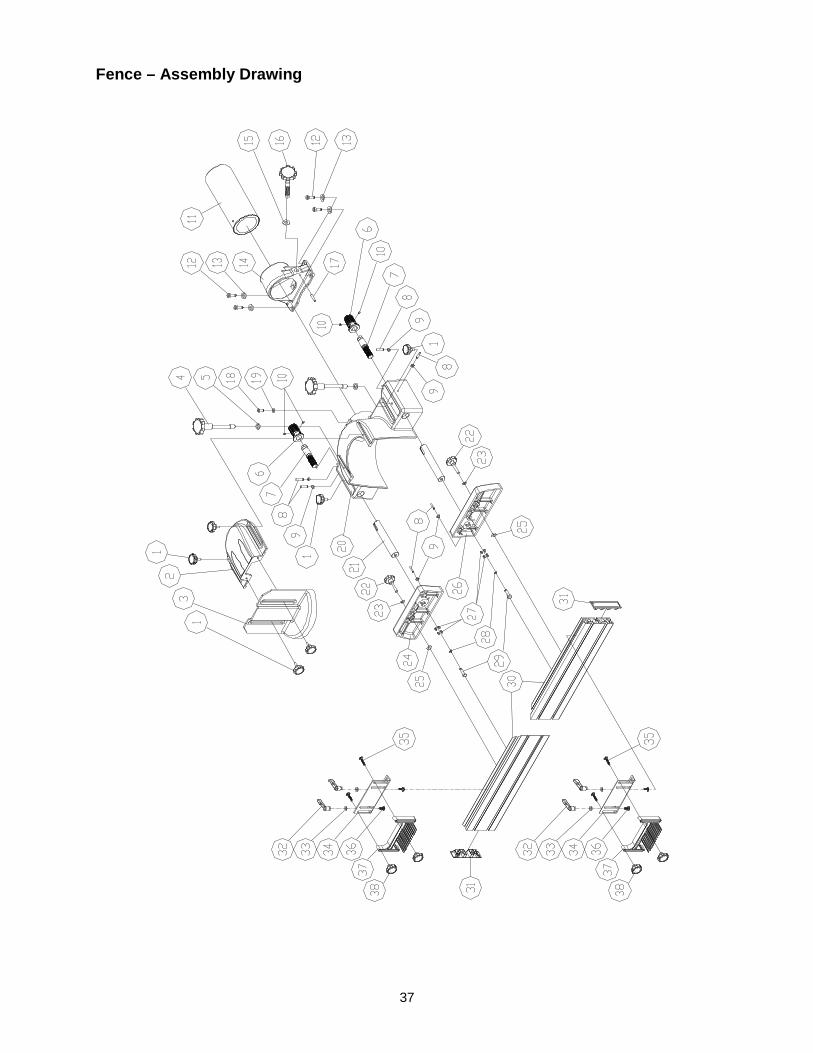
37
Fence – Assembly Drawing
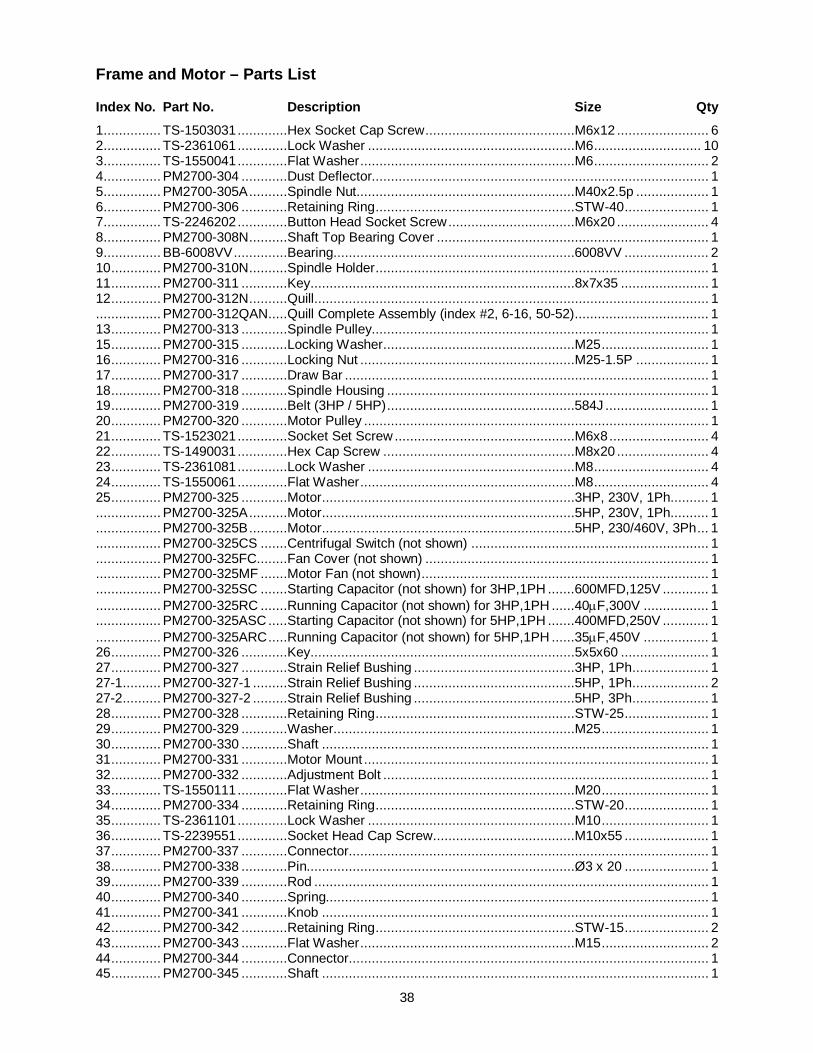
38
Frame and Motor – Parts List
Index No. Part No. Description Size Qty 1 ............... TS-1503031 .............Hex Socket Cap Screw .......................................M6x12 ........................ 6 2 ............... TS-2361061 .............Lock Washer ......................................................M6 ............................ 10 3 ............... TS-1550041 .............Flat Washer ........................................................M6 .............................. 2 4 ............... PM2700-304 ............Dust Deflector........................................................................................ 1 5 ............... PM2700-305A ..........Spindle Nut .........................................................M40x2.5p ................... 1 6 ............... PM2700-306 ............Retaining Ring ....................................................STW-40 ...................... 1 7 ............... TS-2246202 .............Button Head Socket Screw .................................M6x20 ........................ 4 8 ............... PM2700-308N ..........Shaft Top Bearing Cover ....................................................................... 1 9 ............... BB-6008VV ..............Bearing...............................................................6008VV ...................... 2 10 ............. PM2700-310N ..........Spindle Holder ....................................................................................... 1 11 ............. PM2700-311 ............Key.....................................................................8x7x35 ....................... 1 12 ............. PM2700-312N ..........Quill ....................................................................................................... 1 ................. PM2700-312QAN .....Quill Complete Assembly (index #2, 6-16, 50-52) ................................... 1 13 ............. PM2700-313 ............Spindle Pulley........................................................................................ 1 15 ............. PM2700-315 ............Locking Washer ..................................................M25 ............................ 1 16 ............. PM2700-316 ............Locking Nut ........................................................M25-1.5P ................... 1 17 ............. PM2700-317 ............Draw Bar ............................................................................................... 1 18 ............. PM2700-318 ............Spindle Housing .................................................................................... 1 19 ............. PM2700-319 ............Belt (3HP / 5HP) .................................................584J ........................... 1 20 ............. PM2700-320 ............Motor Pulley .......................................................................................... 1 21 ............. TS-1523021 .............Socket Set Screw ...............................................M6x8 .......................... 4 22 ............. TS-1490031 .............Hex Cap Screw ..................................................M8x20 ........................ 4 23 ............. TS-2361081 .............Lock Washer ......................................................M8 .............................. 4 24 ............. TS-1550061 .............Flat Washer ........................................................M8 .............................. 4 25 ............. PM2700-325 ............Motor ..................................................................3HP, 230V, 1Ph .......... 1 ................. PM2700-325A ..........Motor ..................................................................5HP, 230V, 1Ph .......... 1 ................. PM2700-325B ..........Motor ..................................................................5HP, 230/460V, 3Ph ... 1 ................. PM2700-325CS .......Centrifugal Switch (not shown) .............................................................. 1 ................. PM2700-325FC........Fan Cover (not shown) .......................................................................... 1 ................. PM2700-325MF .......Motor Fan (not shown) ........................................................................... 1 ................. PM2700-325SC .......Starting Capacitor (not shown) for 3HP,1PH .......600MFD,125V ............ 1 ................. PM2700-325RC .......Running Capacitor (not shown) for 3HP,1PH ......40μF,300V ................. 1 ................. PM2700-325ASC .....Starting Capacitor (not shown) for 5HP,1PH .......400MFD,250V ............ 1 ................. PM2700-325ARC .....Running Capacitor (not shown) for 5HP,1PH ......35μF,450V ................. 1 26 ............. PM2700-326 ............Key.....................................................................5x5x60 ....................... 1 27 ............. PM2700-327 ............Strain Relief Bushing ..........................................3HP, 1Ph .................... 1 27-1 .......... PM2700-327-1 .........Strain Relief Bushing ..........................................5HP, 1Ph .................... 2 27-2 .......... PM2700-327-2 .........Strain Relief Bushing ..........................................5HP, 3Ph .................... 1 28 ............. PM2700-328 ............Retaining Ring ....................................................STW-25 ...................... 1 29 ............. PM2700-329 ............Washer...............................................................M25 ............................ 1 30 ............. PM2700-330 ............Shaft ..................................................................................................... 1 31 ............. PM2700-331 ............Motor Mount .......................................................................................... 1 32 ............. PM2700-332 ............Adjustment Bolt ..................................................................................... 1 33 ............. TS-1550111 .............Flat Washer ........................................................M20 ............................ 1 34 ............. PM2700-334 ............Retaining Ring ....................................................STW-20 ...................... 1 35 ............. TS-2361101 .............Lock Washer ......................................................M10 ............................ 1 36 ............. TS-2239551 .............Socket Head Cap Screw .....................................M10x55 ...................... 1 37 ............. PM2700-337 ............Connector.............................................................................................. 1 38 ............. PM2700-338 ............Pin......................................................................Ø3 x 20 ...................... 1 39 ............. PM2700-339 ............Rod ....................................................................................................... 1 40 ............. PM2700-340 ............Spring.................................................................................................... 1 41 ............. PM2700-341 ............Knob ..................................................................................................... 1 42 ............. PM2700-342 ............Retaining Ring ....................................................STW-15 ...................... 2 43 ............. PM2700-343 ............Flat Washer ........................................................M15 ............................ 2 44 ............. PM2700-344 ............Connector.............................................................................................. 1 45 ............. PM2700-345 ............Shaft ..................................................................................................... 1
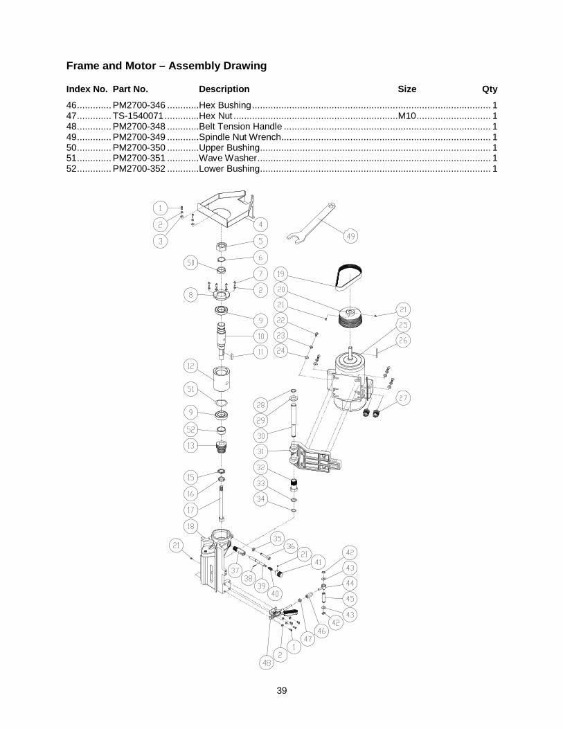
39
Frame and Motor – Assembly Drawing
Index No. Part No. Description Size Qty 46 ............. PM2700-346 ............Hex Bushing .......................................................................................... 1 47 ............. TS-1540071 .............Hex Nut ..............................................................M10 ............................ 1 48 ............. PM2700-348 ............Belt Tension Handle .............................................................................. 1 49 ............. PM2700-349 ............Spindle Nut Wrench ............................................................................... 1 50 ............. PM2700-350 ............Upper Bushing....................................................................................... 1 51 ............. PM2700-351 ............Wave Washer ........................................................................................ 1 52 ............. PM2700-352 ............Lower Bushing....................................................................................... 1

40
Elevator – Parts List
Index No. Part No. Description Size Qty 1 ............... PM2700-501 ............Lead Screw ........................................................................................... 1 2 ............... PM2700-342 ............Retaining Ring ....................................................STW-15 ...................... 1 3 ............... PM2700-503 ............Thrust Bearing ....................................................51202 ......................... 2 4 ............... PM2700-504 ............Hex Nut ..............................................................M20-1.5P ................... 4 5 ............... PM2700-505 ............Adjusting Bolt ........................................................................................ 4 6 ............... TS-2361121 .............Lock Washer ......................................................M12 ............................ 4 7 ............... TS-1506141 .............Socket Head Cap Screw .....................................M12x90 ...................... 4 8 ............... PM2700-508 ............Socket Set Screw ...............................................M8x30 ........................ 4 9 ............... TS-1540061 .............Hex Nut ..............................................................M8 .............................. 4 10 ............. PM2700-510 ............Gib ........................................................................................................ 1 11 ............. TS-1505021 .............Socket Head Cap Screw .....................................M10x20 ...................... 1 12 ............. PM2700-512 ............Housing ................................................................................................. 1 13 ............. PM2700-513 ............Right Worm Gear................................................................................... 1 13-1 .......... PM2700-513-1 .........Left Worm Gear ..................................................................................... 1 14 ............. PM2700-514 ............Bushing ................................................................................................. 1 15 ............. PM2700-515 ............Sensor Plate .......................................................................................... 1 16 ............. TS-2342102 .............Nylon Insert Lock Nut .........................................M10-1.25P.................. 1 17 ............. TS-1522011 .............Socket Set Screw ...............................................M5x6 .......................... 4 18 ............. TS-0270021 .............Socket Set Screw ...............................................5/16”-18x5/16” ............ 5 19 ............. PM2700-519 ............Fixing Ring ............................................................................................ 2 20 ............. PM2700-520 ............Washer...............................................................M19 ............................ 2 21 ............. PM2700-521 ............Woodruff Key......................................................................................... 1 22 ............. PM2700-522 ............Key.....................................................................5x5x20 ....................... 1 23 ............. PM2700-523 ............Shaft ..................................................................................................... 1 24 ............. PM2000-202 ............Hand Wheel .......................................................................................... 1 25 ............. PM2700-525 ............Handle................................................................................................... 1 26 ............. PM2700-526 ............Knob ..................................................................................................... 1 27 ............. PM2700-527 ............Bracket .................................................................................................. 1 28 ............. PM2700-528 ............Tapping Screw ...................................................M3-1.06Px6 ................ 2 29 ............. TS-2361061 .............Lock Washer ......................................................M6 .............................. 2 30 ............. TS-1534042 .............Phillips Pan Head Machine Screw ......................M6x12 ........................ 2 31 ............. PM2700-531 ............Cap ....................................................................................................... 1 32 ............. PM2700-532 ............Round Head Screw ............................................M4x8 .......................... 1 33 ............. PM2700-533 ............Cord Clamp ........................................................................................... 1 34 ............. PM2700-534 ............Key.....................................................................5x5x12 ....................... 2 35 ............. PM2700-535 ............Flat Washer ........................................................M10 ............................ 1 36 ............. PM2700-536 ............Cover .................................................................................................... 1 37 ............. PM2700-537 ............Slotted Round Head Machine Screw...................M6-1.0P x 12 .............. 3 38 ............. PM2700-538 ............Flat Washer ........................................................................................... 1 39 ............. PM2700-539 ............Plate ...................................................................................................... 1 40 ............. PM2700-540 ............Slotted Round Head Machine Screw...................M6-1.0P x 25 .............. 3
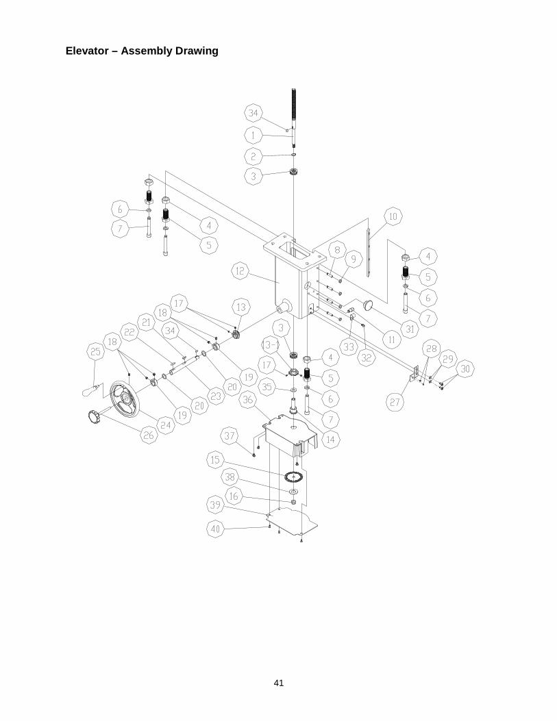
41
Elevator – Assembly Drawing

42
Caster Assembly – Parts List
Index No. Part No. Description Size Qty 1 ............... TS-2342141 .............Nylon Insert Lock Nut .........................................M14 ............................ 4 2 ............... PM2700-602 ............Sprocket ................................................................................................ 4 3 ............... BB-6002ZZ ..............Ball Bearing ........................................................6002ZZ....................... 4 4 ............... PM2700-503 ............Thrust Bearing ....................................................51202 ......................... 4 5 ............... PM2700-605 ............Shaft ..................................................................................................... 3 6 ............... TS-1504101 .............Socket Head Cap Screw .....................................M8x50 ........................ 8 7 ............... PM2700-217 ............Spring Pin...........................................................Ø5 x 32 ...................... 1 8 ............... PM2700-608 ............Lead Screw Shaft .................................................................................. 1 9 ............... PM2700-609 ............Gear Shaft ............................................................................................. 1 10 ............. PM2700-610 ............Key.....................................................................4x4x16 ....................... 1 11 ............. PM2700-611 ............Lead Shaft ............................................................................................. 1 12 ............. TS-1550061 .............Flat Washer ........................................................M8 .............................. 2 13 ............. PM2700-613 ............Elevating Block ...................................................................................... 4 14 ............. PM2700-614 ............Caster ................................................................................................... 4 15 ............. TS-2361081 .............Lock Washer ......................................................M8 .............................. 8 16 ............. TS-1504041 .............Socket Head Cap Screw .....................................M8x20 ...................... 10 17 ............. PM2700-617 ............Chain .................................................................................................... 1 18 ............. PM2700-618 ............Sprocket Bracket ................................................................................... 1 19 ............. PM2700-342 ............Retaining Ring ....................................................STW-15 ...................... 2 20 ............. PM2700-620 ............Gear ...................................................................................................... 1 21 ............. PM2700-621 ............Retaining Ring ....................................................RTW-32 ...................... 2 22 ............. BB-6002ZZ ..............Ball Bearing ........................................................6002ZZ....................... 2 23 ............. TS-1504061 .............Socket Head Cap Screw .....................................M8x30 ........................ 2 24 ............. TS-1550061 .............Flat Washer ........................................................M8 .............................. 2 25 ............. PM2700-625 ............Gear Housing ........................................................................................ 1 26 ............. PM2700-626 ............Handle................................................................................................... 1 27 ............. PM2000-202 ............Hand Wheel .......................................................................................... 1 28 ............. TS-0270021 .............Socket Set Screw ...............................................5/16”-18x5/16” ............ 1 29 ............. PM2700-522 ............Key.....................................................................5x5x20 ....................... 1
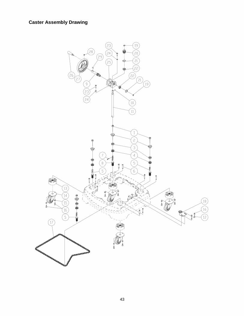
43
Caster Assembly Drawing

44
Spindle Assembly – Parts List
Index No. Part No. Description Size Qty 1 ............... TS-1505031 .............Socket Head Cap Screw .....................................M10x25 ...................... 4 2 ............... PM2700-702 ............Pin......................................................................................................... 2 3 ............... PM2700-703 ............Special Washer ..................................................................................... 1 4 ............... PM2700-704 ............Keyed Collar .......................................................................................... 1 5 ............... PM2700-705 ............Collar .................................................................I.D. 1-1/4” x 3/4”T ....... 5 6 ............... PM2700-706 ............Collar .................................................................I.D. 1-1/4” x 1/2”T ....... 3 7 ............... PM2700-707 ............Spindle ...............................................................1-1/4” ......................... 1 ................. PM2700-707A ..........Spindle Assembly (#1 thru #7, #32) ....................1-1/4” ......................... 1 8 ............... PM2700-708 ............Special Washer ..................................................................................... 1 9 ............... PM2700-709 ............Keyed Collar .......................................................................................... 1 10 ............. PM2700-710 ............Collar .................................................................I.D. 3/4” x 1/2”T .......... 4 11 ............. PM2700-711 ............Collar .................................................................I.D. 3/4” x 3/4”T .......... 2 12 ............. PM2700-712 ............Spindle ...............................................................3/4”............................. 1 ................. PM2700-712A ..........Spindle Assembly (#1, #8 thru #12, #32) .............3/4”............................. 1 13 ............. PM2700-713 ............Special Washer ..................................................................................... 1 14 ............. PM2700-714 ............Keyed Collar .......................................................................................... 1 15 ............. PM2700-715 ............Collar .................................................................I.D. 1” x 3/4”T ............. 4 16 ............. PM2700-716 ............Collar .................................................................I.D. 1” x 1/2”T ............. 4 17 ............. PM2700-717 ............Spindle ...............................................................1” ............................... 1 ................. 1791205...................Spindle Assembly (#1, #13 thru #17, #32)* .........1” ............................... 1 30 ............. 1791207...................Collet* ................................................................1/4”............................. 1 31 ............. 1791208...................Collet* ................................................................1/2”............................. 1 32 ............. PM2700-305A ..........Spindle Nut .........................................................M40x2.5p ................... 1 * Optional accessory
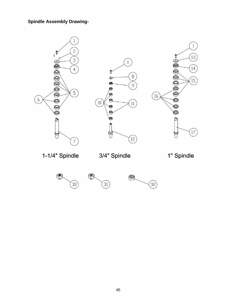
45
Spindle Assembly Drawing-

46
Cabinet and Base – Parts List
Index No. Part No. Description Size Qty 1 ............... TS-1533052 .............Phillips Pan Head Machine Screw ......................M5x16 ........................ 8 2 ............... TS-2361051 .............Lock Washer ......................................................M5 .............................. 4 3 ............... TS-1550031 .............Flat Washer ........................................................M5 .............................. 4 4 ............... PM2700-404 ............Dust Chute ............................................................................................ 1 5 ............... TS-1533032 .............Phillips Pan Head Machine Screw ......................M5x10 ...................... 13 6 ............... TS-2361051 .............Lock Washer ......................................................M5 .............................. 6 7 ............... PM2700-407 ............Dust Deflector........................................................................................ 1 8 ............... PM2700-408 ............Padding ................................................................................................. 2 9 ............... PM2700-409 ............Cabinet.................................................................................................. 1 10 ............. TS-1504041 .............Socket Head Cap Screw .....................................M8x20 ........................ 6 11 ............. TS-2361081 .............Lock Washer ......................................................M8 .............................. 6 12 ............. TS-1550071 .............Flat Washer ........................................................M10 ............................ 4 13 ............. TS-2361101 .............Lock Washer ......................................................M10 ............................ 4 14 ............. TS-1491031 .............Hex Cap Screw ..................................................M10x25 ...................... 4 15 ............. PM2700-415 ............Strain Relief ........................................................................................... 1 16 ............. PM2700-416 ............Bumper ................................................................................................. 2 17 ............. TS-1541001 .............Nylon Insert Lock Nut .........................................M4 .............................. 2 18 ............. TS-1550021 .............Flat Washer ........................................................M4 .............................. 6 19 ............. TS-2284082 .............Pan Head Screw ................................................M4x8 .......................... 2 20 ............. PM2700-420 ............Bracket .................................................................................................. 1 21 ............. PM2700-421 ............Limit Switch ........................................................................................... 1 22 ............. PM2700-422 ............Limit Switch Cover ................................................................................. 1 23 ............. TS-2284352 .............Pan Head Screw ................................................M4x35 ........................ 2 24 ............. TS-0810012 .............Slotted Round Head Machine Screw...................#10-24x1/4” ................ 1 25 ............. PM2700-425 ............Junction Box Cover ............................................................................... 1 29 ............. PM2700-429 ............Junction Box .......................................................................................... 1 30 ............. PM2700-430 ............Strain Relief ........................................................3HP, 1Ph; 5HP, 1Ph ... 2 30-1 .......... PM2700-430-1 .........Strain Relief ........................................................5HP, 3Ph .................... 2 31 ............. TS-2311061 .............Hex Nut ..............................................................M6 .............................. 4 32 ............. TS-2361061 .............Lock Washer ......................................................M6 ............................ 10 33 ............. PM2700-433 ............Window ................................................................................................. 1 34 ............. PM2700-434 ............Door ...................................................................................................... 1 35 ............. TS-1534042 .............Phillips Pan Head Machine Screw ......................M6x12 ........................ 8 36 ............. PM2700-436 ............Door Latch............................................................................................. 1 37 ............. TS-0813022 .............Slotted Round Head Machine Screw...................1/4”-20x3/8” ................ 2 38 ............. TS-0680021 .............Flat Washer ........................................................1/4”............................. 2 39 ............. PM2000-105 ............POWERMATIC Name Plate................................................................... 1 40 ............. PM2700-440 ............Wide Stripe ............................................................................................ 2 41 ............. PM2700-441 ............Narrow Stripe ........................................................................................ 2 42 ............. PM2700-442 ............DRO Sensor Assembly .......................................................................... 1 ................. PM2700-442SC .......Sensor Cord w/ Sensor .......................................................................... 1 ................. PM2700-442ICBN ....DRO IC Board (225K/630V Capacitor) ................................................... 1 43 ............. PM2700-443 ............Strain Relief ........................................................3HP, 1Ph .................... 3 43-1 .......... PM2700-443-1 .........Strain Relief (not shown).....................................5HP, 1Ph .................... 4 43-2 .......... PM2700-443-2 .........Strain Relief (not shown).....................................5HP, 3Ph .................... 3 44 ............. PM2700-444 ............Tapping Screw ...................................................M4x12 ........................ 4 45 ............. PM2700-445N ..........Switch Plate .......................................................3HP 1Ph, 5HP 1Ph ..... 1 ................. PM2700-445N-1.......Switch Plate .......................................................5HP, 3Ph .................... 1 45-1 .......... PM2700-445-1 .........Cap ....................................................................................................... 1 46 ............. PM2700-446 ............DRO Cover ............................................................................................ 1 47 ............. TS-1531012 .............Phillips Pan Head Machine Screw ......................M3x6 .......................... 4 48 ............. PM2700-448 ............Forward/Reverse Switch .....................................3HP/1Ph ..................... 1 ................. PM2700-448A ..........Forward/Reverse Switch .....................................5HP/1Ph ..................... 1 ................. PM2700-448B ..........Forward/Reverse Switch .....................................5HP/3Ph ..................... 1 49 ............. PM2700-449 ............Plate ...................................................................................................... 1

47
Index No. Part No. Description Size Qty 50 ............. PM2700-450 ............Cap ....................................................................................................... 3 51 ............. PM2700-451 ............Limit Switch Cord................................................................................... 1 52 ............. PM2700-452 ............Base ...................................................................................................... 1 53 ............. TS-1550061 .............Flat Washer ........................................................M8 .............................. 6 54 ............. PM2700-454 ............Motor Cable 3HP, 1Ph ........................................14AWG x 4C .............. 1 ................. PM2700-454A ..........Motor Cable 5HP, 1Ph ........................................12AWG x 3C .............. 1 54-1 .......... PM2700-454-1A .......Motor Cable 5HP, 1Ph ........................................12AWG x 2C .............. 1 ................. PM2700-454B ..........Motor Cable 5HP, 3Ph (600V, ST,CSA/UL).........14AWG x 4C .............. 1 55 ............. PM2700-455 ............Star Washer .......................................................M5x10 ........................ 3 56 ............. PM2700-113 ............Tapping Screw ...................................................M5-2.12Px25 .............. 2 57 ............. PM2700-114 ............Magnetic Switch .................................................3HP, 230V, 1Ph .......... 1 ................. PM2700-114A ..........Magnetic Switch .................................................5HP, 230V, 1Ph .......... 1 ................. PM2700-114B ..........Magnetic Switch .................................................5HP, 230V, 3Ph .......... 1 ................. PM2700-114C ..........Magnetic Switch .................................................5HP, 460V, 3Ph .......... 1 58 ............. PM2700-115 ............Power Cord ........................................................3HP, 1Ph 14AWGx3C 1 ................. PM2700-115A ..........Power Cord ........................................................5HP, 1Ph 12AWGx3C 1 ................. PM2700-115B ..........Power Cord (600V, ST,CSA/UL) .........................5HP, 3Ph 14AWGx4C 1 59 ............. PM2700-159 ............Cable & Connector, (KST Male & Female) ..........3HP 1PH, 14AWGx3C 1 ................. PM2700-159A ..........Cable & Connector, (KST Male & Female) ..........5HP 1PH, 12AWGx3C 1 ................. PM2700-159B ..........Cable & Connector, (KST Male & Female) ..........5HP 3PH, 14AWGx4C 1 60 ............. PM2700-160 ............Cable & Connector, (2000 Male & Female) .........3HP 1PH, 18AWGx4C 1 ................. PM2700-160A ..........Cable & Connector, (2000 Male & Female) .........5HP 1PH, 18AWGx4C 1 ................. PM2700-160B ..........Cable & Connector, (2000 Male & Female) .........5HP 3PH, 18AWGx4C 1 61 ............. PM2700-461 ............Strain Relief ........................................................KSS SR-7R3 .............. 2 62 ............. PM2700-462 ............Strain Relief ........................................................KSS PG11 .................. 1 62-1 .......... PM2700-462-1 .........Strain Relief ........................................................MG25A-16B ............... 1 63 ............. PM2700-463 ............Plate ...................................................................................................... 1 64 ............. PM2700-464 ............Strain Relief ........................................................AVC MG25A-16 .......... 2 65 ............. PM2700-465 ............PC Sticker ............................................................................................. 1
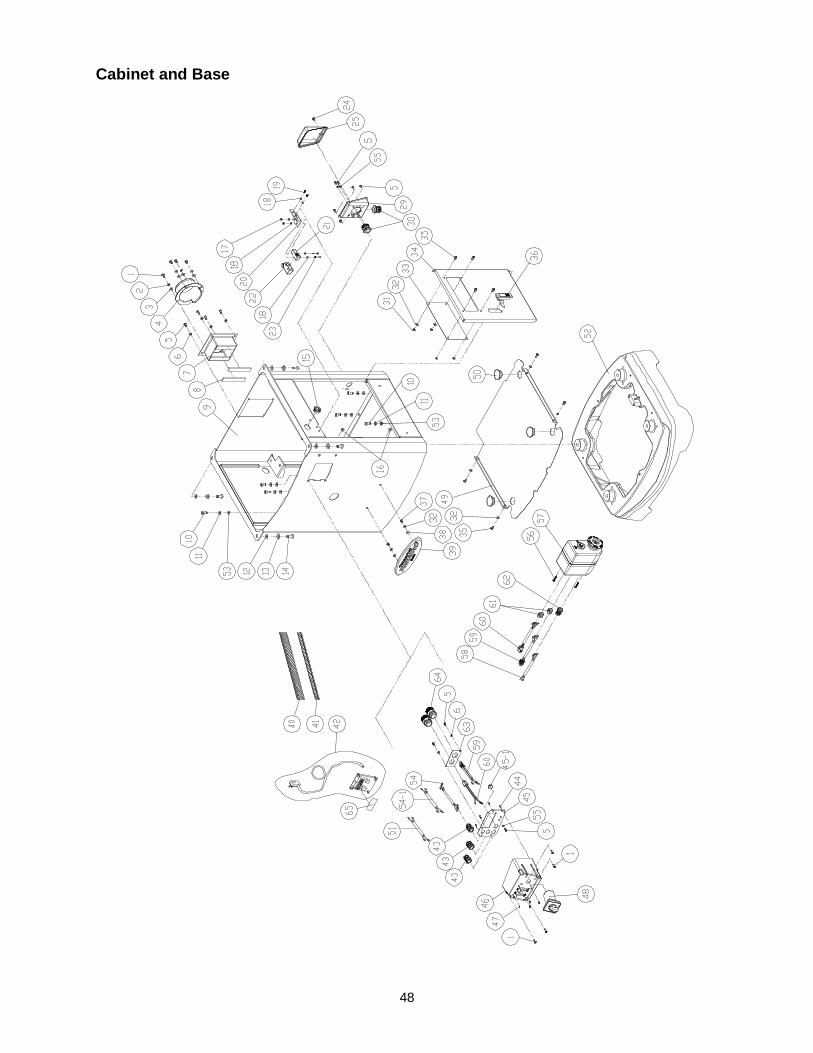
48
Cabinet and Base
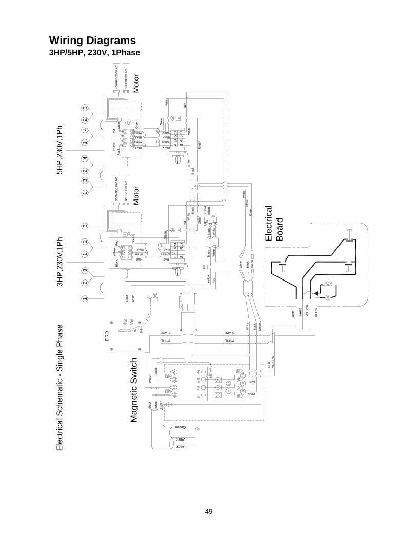
49
Wiring Diagrams 3HP/5HP, 230V, 1Phase
Black
White
Green
Bla
ckW
hite
Gre
enW
hite
Bla
ck
Black
Red
Lim
ited
switc
h
Red
Yel
low
Bla
ck
Whi
te
Bla
ck
Whi
te
DR
O
Whi
te
Bla
ck
Mot
or
Black
White
Red
Gre
en
YELL
OW
WH
ITE
RED
BLA
CK
LED
BLACK
WHITE
RED
YEL
LOW
Elec
trica
lBo
ard
Mag
netic
Sw
itch
3HP
,230
V,1P
h
600M
FD/1
25V
.AC
40U
F/12
5V.A
C
Mot
or
Black
White
Gre
en
Gre
en
Bla
ckW
hite
Black
White
Whi
te
5HP,
230V
,1Ph
400M
FD/2
50V
.AC
35U
F/45
0V.A
C
Elec
trica
l Sch
emat
ic -
Sin
gle
Phas
e
U5
V14
SR
13
VU
514
S6
13R
WHITE
BLACK
Whi
te
Bla
ck
Gre
en
Gre
enG
reen
Whi
teB
lack
Gre
en
Gre
en
Red
Red
Bla
ckW
hite
Whi
te
Whi
te
Bla
ckG
reen
12
31
23
24
14
13
23
White WhiteBlack Black
Red
Yel
low
Bla
ckY
ello
wB
lack
Whi
teR
ed
Black
White
Red
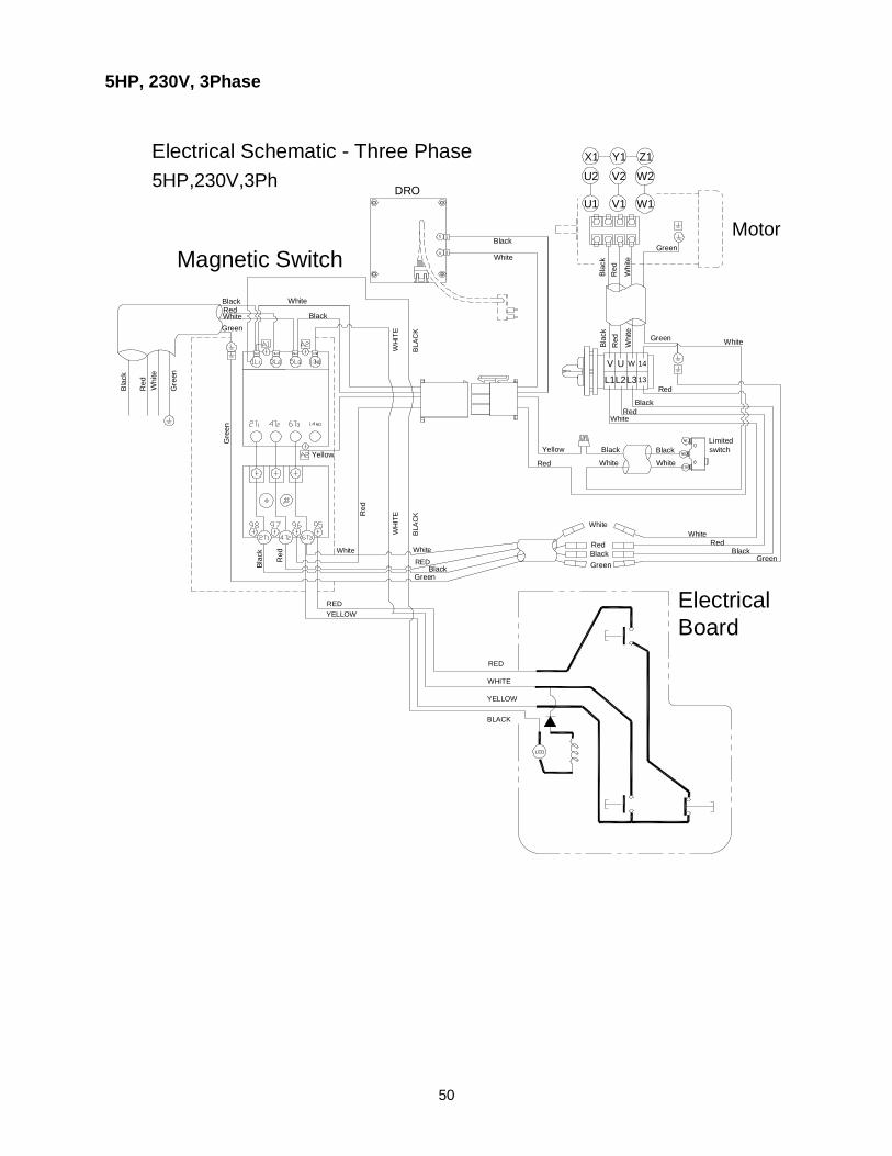
50
5HP, 230V, 3Phase
Black White
GreenWhite Black
Yellow
Blac
k
Red
Limitedswitch
Red
Yellow Black
White
Black
White
DRO
White
BlackMotor
Whi
te
Red
Blac
k
Green
Black
Blac
kR
ed
Whi
te
YELLOW
WHITE
RED
BLACK
LED
BLA
CK
WH
ITE
REDYELLOW
Red
5HP,230V,3PhElectrical Schematic - Three Phase
Green
Red
Red
V U W 14
L1L2L313
WH
ITE
BLA
CK
ElectricalBoard
Magnetic Switch
Green
White
Gre
en
White
REDBlack
Green
White
Red
White
BlackRed
White
RedBlackGreen
White
X1 Y1 Z1
U1 V1 W1
W2V2U2
Bla
ck
Whi
te
Gre
en
Red
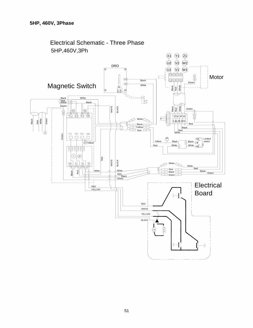
51
5HP, 460V, 3Phase
Black White
GreenWhite Black
Yellow
Bla
ck
Red
Limitedswitch
Red
Yellow Black
White
Black
White
DRO
White
BlackMotor
Whi
te
Red
Bla
ck
Green
BlackB
lack
Red
Whi
te
YELLOW
WHITE
RED
BLACK
LED
BLAC
K
WH
ITE
REDYELLOW
Red
5HP,460V,3PhElectrical Schematic - Three Phase
Green
Red
Red
UV W 14
L1L2L313
WH
ITE
BLAC
K
ElectricalBoard
Magnetic Switch
Green
White
Gre
en
White
REDBlack
Green
White
Red
White
BlackRed
White
BlackYellowRed
White
BlackRed
Green
W1V1U1
U2
X1
V2 W2
Y1 Z1
Whi
te
Bla
ck
Red
Gre
en

52
427 New Sanford Road LaVergne, TN 37086 Phone: 800-274-6848
www.powermatic.com