only copy preview · 2014-05-21 · taken to mean the latest edition of the code, specification or...
TRANSCRIPT
“P
REVI
EW C
OPY O
NLY”

“P
REVI
EW C
OPY O
NLY”

Transnet Pipelines A4XY-TPL-265-001 Phase 1 – NKP – TLP010 Revision: 0 Date: February 2010 Contract No. A4XY Page 1 of 11
TRANSNET PIPELINES TECHNICAL STANDARD
ELECTRIC FENCE PERIMETER BARRIER PROTECTION SPECIFICATION TO MEET NATIONAL KEY POINT REQUIREMENTS
Rev Date Revision Description
Issued by Checked by Approved by Fluor Igoda
Approved by Transnet Pipelines
0 08 Sep 09 For Client Approval
C. Vere M. Hounsome P. Bennett N. Ndlovu
“P
REVI
EW C
OPY O
NLY”

Transnet Pipelines A4XY-TPL-265-001 Phase 1 – NKP – TLP010 Revision: 0 Date: February 2010 Contract No. A4XY Page 2 of 11
TPL Technical Standards Number: A4XY-TPL-265-001 Title: Electric Fence Perimeter Barrier Protection Specifications to Meet NKP Requirements Date of Adoption: XX/XX/2010 Revision Number: 00
Change Record
Date Change Revision
“P
REVI
EW C
OPY O
NLY”

Transnet Pipelines A4XY-TPL-265-001 Phase 1 – NKP – TLP010 Revision: 0 Date: February 2010 Contract No. A4XY Page 3 of 11
TABLE OF CONTENTS
1. INTRODUCTION ..............................................................................................................................4 1.1. SCOPE ................................................................................................................................................ 4 1.2. BACKGROUND TO NKP REQUIREMENTS............................................................................... 4 1.3. REFERENCES................................................................................................................................... 4 1.4. LEGISLATION, SPECIFICATIONS, DRAWINGS, ATTACHMENTS AND EXHIBITS....... 4 1.5. GENERAL.......................................................................................................................................... 6 1.6. GENERAL SYSTEM REQUIREMENTS....................................................................................... 6
2 ELECTRIC FENCE SYSTEM...........................................................................................................7 2.1. FENCE ENERGIZER ....................................................................................................................... 8 2.2 CONDUCTING WIRE...................................................................................................................... 9 2.3 FENCE POSTS, INSULATORS AND LEAD OUT CABLE......................................................... 9 2.4 EARTHING AND LIGHTNING PROTECTION .......................................................................... 9
3 INSTALLATION REQUIREMENTS ...............................................................................................10 3.1. CONSTRUCTION ........................................................................................................................... 10 3.2. TESTING.......................................................................................................................................... 10
4 MANUFACTURERS CERTIFICATION..........................................................................................11
“P
REVI
EW C
OPY O
NLY”

Transnet Pipelines A4XY-TPL-265-001 Phase 1 – NKP – TLP010 Revision: 0 Date: February 2010 Contract No. A4XY Page 4 of 11
1. INTRODUCTION
1.1. SCOPE
This Transnet Pipelines Specification covers the minimum requirements for the design and installation of a new permanent perimeter wall-top Electric Security Fence. It does not cover special security measures that may be required such as CCTV, security guards and other specialty fencing systems.
1.2. BACKGROUND TO NKP REQUIREMENTS
The Grading of National Key Points (NKP): Security Advisory Service has graded the Transnet Pipeline Depots in order to determine the Class of the Facilities and the level of security required. The following aspects / phenomena were taken into consideration before grading the depots: Location Crime threat analysis History of aggression against resident / residence Strategic reason / value for being a National Key Point
The Transnet Pipelines depots were subsequently classified as National Key Points with a High Level of Security: Level 3. As a result of this classification NKP provided guidelines for the types and details of acceptable perimeter barriers and gates.
1.3. REFERENCES
Annexure A of the Grading of National Key Points: Security Advisory Service was used as the basis for this specification. It is noted that said document must be used as a guideline and that threats, topographical description and other factors may influence the security system(s) proposed for a depot.
1.4. LEGISLATION, SPECIFICATIONS, DRAWINGS, ATTACHMENTS AND EXHIBITS
All Work shall be performed in strict accordance with the following described specifications, drawings and other documents, where applicable and which by this reference are made a part hereof. Where reference is made to a Code, Specification or Standard, the reference shall be taken to mean the latest edition of the Code, Specification or Standard, including addenda, supplements and revisions thereto, in content or numbering.
“P
REVI
EW C
OPY O
NLY”
Transnet Pipelines A4XY-TPL-265-001 Phase 1 – NKP – TLP010 Revision: 0 Date: February 2010 Contract No. A4XY Page 5 of 11
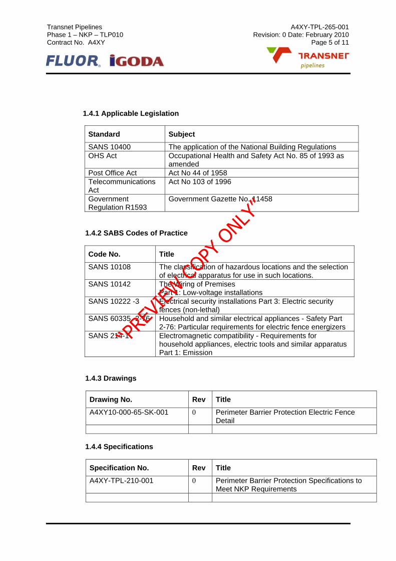
1.4.1 Applicable Legislation
Standard Subject
SANS 10400 The application of the National Building Regulations OHS Act Occupational Health and Safety Act No. 85 of 1993 as
amended Post Office Act Act No 44 of 1958 Telecommunications Act
Act No 103 of 1996
Government Regulation R1593
Government Gazette No. 11458
1.4.2 SABS Codes of Practice
Code No. Title
SANS 10108 The classification of hazardous locations and the selection of electrical apparatus for use in such locations.
SANS 10142 The Wiring of Premises Part 1: Low-voltage installations
SANS 10222 -3 Electrical security installations Part 3: Electric security fences (non-lethal)
SANS 60335 -2-76 Household and similar electrical appliances - Safety Part 2-76: Particular requirements for electric fence energizers
SANS 214-1 Electromagnetic compatibility - Requirements for household appliances, electric tools and similar apparatus Part 1: Emission
1.4.3 Drawings
Drawing No. Rev Title
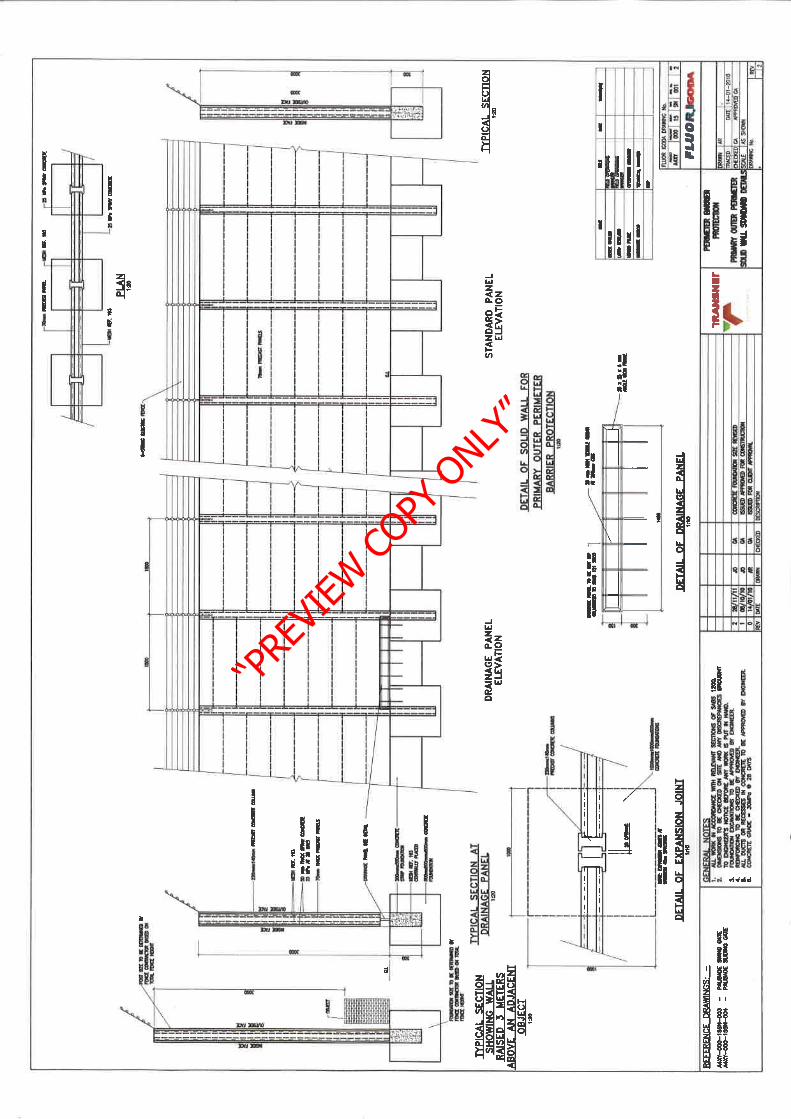
A4XY10-000-65-SK-001 0 Perimeter Barrier Protection Electric Fence Detail
1.4.4 Specifications
Specification No. Rev Title
A4XY-TPL-210-001 0 Perimeter Barrier Protection Specifications to Meet NKP Requirements
“P
REVI
EW C
OPY O
NLY”

Transnet Pipelines A4XY-TPL-265-001 Phase 1 – NKP – TLP010 Revision: 0 Date: February 2010 Contract No. A4XY Page 6 of 11
1.5. GENERAL
The electric fence shall be 6 strands mounted on top of a solid wall, steel palisade fence or steel mesh fence and shall provide a physical barrier to detect any intrusion attempts. The system shall operate as a zoned, automatic, supervised, detection sensor system, capable of integration with the Security Management System (SMS) to detect and annunciate an attempted breach of the perimeter fence by an intruder. Should any person attempt to defeat the electric fence by way of climbing, touching, cutting or spacing the wires an alarm shall be annunciated as a perimeter alarm on the security management system.
The Electric Fence System (EFS) shall:
Be installed on the perimeter barrier fence as described in the perimeter fence specification and integrated to the security management system.
Monitor the status of fence cabling, devices, tampers and the like and provide control of zone status (i.e. isolate/access/secure)
Provide independent zone control and alarm display via the security management system.
Provide full performance and functionality as described in the relevant specification clauses.
1.6. GENERAL SYSTEM REQUIREMENTS
The electric fence system shall be made up of a horizontal grid of alternate positive and earth wires. The electric fence shall be a proven system with demonstrated performance to detect:
A short on the fence caused by climbing or other interference with the fence structure.
Cutting of any wire or lead-out to the fence structure.
Tampering with any of the system enclosures, energizer monitor units, or remote keypads.
The accidental or willful loss of mains power, battery power, and the communication system of the electric fence controllers to the security management system.
“P
REVI
EW C
OPY O
NLY”
Transnet Pipelines A4XY-TPL-265-001 Phase 1 – NKP – TLP010 Revision: 0 Date: February 2010 Contract No. A4XY Page 7 of 11
Fence line energizer performance and alarm sensitivity programming in each zone shall be achieved through local keypad command, and will include the ability to cut power from the energizer in the event of alarm activation. Overall the EFS shall be fully integrated at high level with the SMS for alarm and EFS function monitoring, logging of alarms and the like.
The EFS controller will generate sector and tamper alarm signals, and indicate set or unset on each sector, as well as the status of mains power supply, battery power supply, and the energizer pulse. From the SMS it should be possible to isolate the entire fence system, all zones in any individual sector, or any individual zone in any sector.
Warning signage as required by SANS 60335-2-76:2006(IEC 60335-2-76) shall be provided to both the internal and external sides of the fence to alert personnel of the dangers associated with the non-lethal voltage.
The EFS controllers should have test reports establishing compliance with safety standards and associated amendments of SANS 60335-2-76 and SANS 10222-3 Additionally the controllers should have test reports showing compliance with noise and emission standards SANS 214-1:2009 (CISPR 14 – 1).
The fence structure itself should be built to comply with the requirements of SANS 60335-2-76 and SANS 10222-3.
Any area of non-compliance must be stated.
2 ELECTRIC FENCE SYSTEM
The electric fence system equipment shall include but not limited to the following:
Fence energizer
High tension stainless steel wire
Fencing posts, stays, intermediates, brackets, wire tensioners and insulators.
Warning signs
High tension insulated cabling and conduit
Earthing System
“P
REVI
EW C
OPY O
NLY”

Transnet Pipelines A4XY-TPL-265-001 Phase 1 – NKP – TLP010 Revision: 0 Date: February 2010 Contract No. A4XY Page 8 of 11
2.1. FENCE ENERGIZER
The sectors and zones of the fence shall be powered and controlled by programmable combined energizer monitor units equipped with or linked to an appropriate number of relay boards required for interfacing with the SMS.
The energizer monitor units should have an output energy rating of not less than 4.0 joules and shall be capable of maintaining in excess of 6000 volts over the distance of the wire in any zone.
The fence controllers shall be programmed by PIN operated individual keypads that can if required be located up to 500m from the parent unit.
The energizer monitor units should have the following minimum features:
Be able to be programmed, networked and controlled from various user interfaces, local and remote. Remote access TCP/IP protocols supported shall include http, ppp and snmp.
Alarm outputs to include time programmable siren and strobe light to visually indicate an alarm condition.
High voltage and earth wire monitors to alarm if wires are tampered with.
Connectable to armed response.
Gate monitor input to monitor position of gate.
Lightning and power surge suppression.
Panic button input.
Battery backup system.
Programmable features shall include but not be limited to the following:
Fence line voltage options
Alarm trip voltage options
Fence Alarm Delay Time ( system sensitivity) options
Duress alarm signaling
Keypad and controller cabinet tamper alarm signaling
FASE mode ( Fence Alarm Stops Energizer)
Low voltage monitoring mode
Output tests
“P
REVI
EW C
OPY O
NLY”

Transnet Pipelines A4XY-TPL-265-001 Phase 1 – NKP – TLP010 Revision: 0 Date: February 2010 Contract No. A4XY Page 9 of 11
Diagnostic mode
The fence controllers should have a suitably certified mains power supply and battery backup of not less than 8 hours. The power supplies for all fence controllers shall be connected to a manufacturer approved surge arrestor and not directly to a mains power point. Fence controllers shall be earthed in accordance with applicable standards and the recommendations of manufacturers for specific energizer monitor units.
2.2 CONDUCTING WIRE
The electric fence system shall form an array of horizontal pre-tensioned electrified wires carried on high quality insulators with vertical spacing of not more than 110mm. The fence wire shall be not less than 2.00mm diameter, and shall be stainless steel. Wire tensioning can be achieved by end or in-line strainers and should not be excessive – no more than 20kg load per wire. It should be possible to squeeze together any two neighboring wires with moderate hand pressure.
2.3 FENCE POSTS, INSULATORS AND LEAD OUT CABLE
Fencing posts or brackets shall be manufactured from heavy galvanized steel and be sufficiently rigid to withstand the tension of the electric fence.
Each post should be spaced no more than 3m apart.
For posts requiring pre-punching or pre-drilling galvanizing shall occur after all fittings, mounting holes and the like are provided.
Insulators shall be made from high quality 100% virgin High Density Polyethylene and guaranteed against UV degradation for a period of 10 years.
All high voltage lead-out or underground cable shall be double insulated with an alloy or steel wire core of not less than 1.6mm diameter. Double core double insulated cables may be used for long lead-outs. Joining of lead-out cabling to the fence line wires may be done using crimp sleeves, crimp connectors, or heavy duty line clamps. All lead-out cabling should be contained in protective conduit and every effort must be made to keep it in a single unbroken length leading out to the zone.
All such HV cabling must be kept at least 150mm away from any LV cabling – such as is used for gate monitoring - that should be in a separate conduit. Particular care should be taken with the selection of a route for all such HV cabling. Site engineers should be consulted to ensure there is no risk of interference with any data, communication, PLC, or other LV cabling on site.
2.4 EARTHING AND LIGHTNING PROTECTION
This shall be in accordance with the requirements of SANS 10222-3:2006.The system to be employed shall be copper electrodes plus return earth wire. The earthing system must not be connected to the same earth systems as used by the local electricity supplier or communication provider (or both). The minimum distance
“P
REVI
EW C
OPY O
NLY”

Transnet Pipelines A4XY-TPL-265-001 Phase 1 – NKP – TLP010 Revision: 0 Date: February 2010 Contract No. A4XY Page 10 of 11
between the electric fence energizer earth and any electric supplier or communication system earth system shall be at least 2m.
The electric fence system shall be provided with lightning protection at the fence controllers and the local equipment cubicle.
3 INSTALLATION REQUIREMENTS
3.1. CONSTRUCTION
The electric fence system shall be installed by a manufacturer approved contractor with specialist expertise and experience in their required fields. The use of suitably licensed tradesmen is compulsory.
The fence structure itself should be built to comply with the requirements of SANS 10222-3:2006.
The system shall be installed such that corners, gates, wall interfaces and posts do not cause a security weakness. Anti-climb configurations shall be fitted at all corners, double end strains, gate posts, and any other location where applicable.
The electric fence system shall be installed such that the safety of all persons is maintained during installation and subsequent system of operation.
The electric fence contractor shall be responsible for all cabling, conduit or duct, trenching, concrete, cutting and making good to the satisfaction of the Transnet representative.
All equipment shall be installed in the locations directed by the Transnet representative.
3.2. TESTING
On completion of the fence system all zones should be tested and a test report signed off by the contactor and Transnet representative. Testing shall include the following:
Test fence line voltages
Test all fence alarms by shorting the fence and cutting a wire
Test FASE mode
Test all tamper alarms
Test all system controls and monitoring
Any other tests as appropriate for the site
“P
REVI
EW C
OPY O
NLY”

Transnet Pipelines A4XY-TPL-265-001 Phase 1 – NKP – TLP010 Revision: 0 Date: February 2010 Contract No. A4XY Page 11 of 11
4 MANUFACTURERS CERTIFICATION
The electric fence contractor shall provide the manufacturer’s certification that the electric fence detection system has been installed in accordance with the requisite standards and to the manufacturer’s recommendations.
The electric fence contractor shall offer the appropriate service and maintenance contract to Transnet.
“P
REVI
EW C
OPY O
NLY”