online auction u.s. government property realestatesales
TRANSCRIPT

Progress In Electromagnetics Research, Vol. 105, 425–444, 2010
A TRI-BAND BANDPASS FILTER REALIZED USINGTRI-MODE T-SHAPE BRANCHES
Y. Liu †
College of Information Science and TechnologyNanjing University of Aeronautics and AstronauticsNanjing 210016, China
W. B. Dou
State Key Laboratory of Millimeter WavesSoutheast UniversityNanjing 210096, China
Y. J. Zhao
College of Information Science and TechnologyNanjing University of Aeronautics and AstronauticsNanjing 210016, China
Abstract—In this paper, we present a tri-band filter design usingtri-mode T-shaped branches connected by λ/4 transmission lines.By analyzing the input admittance of a T-shape branch withcommensurate electrical lengths, three resonant modes with twotransmission zeros between are found and design formulas are derived.The filter can be regarded as a combination of three bandpass filterswith only one set of coupling elements. To realize different bandwidthsfor each, the admittance slope of each resonating mode is set asrequired. A genetic algorithm is used in solving related equations toobtain the impedance of each line in a T-shape branch, followed by afinal optimization. A three-pole tri-band filter having passbands of 0.6–0.9, 1.35–1.65 and 2.1–2.4 GHz, is designed, fabricated and measuredwith low passband insertion losses of < 0.7 dB and high rejection of >60 dB between the passband regions. As a generalization, necessary toachieve a tri-band filter with arbitrary passbands, a non-commensurateversion of the T-shape branch is introduced. An example filter design
Corresponding author: Y. Liu ([email protected]).† Also with State Key Laboratory of Millimeter Waves, Southeast University, Nanjing210096, China.
426 Liu, Dou, and Zhao
is given with the passbands asymmetrically located at 0.7–1, 1.65–1.95, and 2.2–2.3 GHz. This technique is able to achieve good designflexibility with respect to bandwidth ratios. This is validated bystudying the maximum impedance variations of a T-shape branch whenthe bandwidth ratios vary.
1. INTRODUCTION
Wireless communication has experienced rapid development in thelast two decades, with several communication standards emerging,such as global system for mobile communication (GSM), personalcommunication system (PCS), and wideband code division multipleaccess (WCDMA), etc. These require modern RF front ends to supportmulti-standard operations. Also, RF coverage systems always needto combine several communication channels while rejecting unwantedsignals. In [1], Lin presents a typical tri-band transceiver for generalpacket radio service (GPRS) applications. To satisfy the need ofmulti-band systems dual-band and tri-band filter have attracted muchinterest, and several techniques have been proposed. A coupling-matrixdesign procedure for tri-band filters in which cross-coupling that canachieve transmission zeros is used to split a wide passband into twoor three separate passbands, is presented in [2]. However, in thismethod the passbands can not be widely spaced due to the bandwidthlimitation of traditional coupled resonator filters.
A tri-band filter based on dual behavior resonators is reported [3]in which several bandstop structures are placed in parallel to constructthe passbands. The reported performance is relatively poor, havinghigher insertion losses compared with the filters introduced here, aswell as spurious responses.
In [4], a mixed bandpass-bandstop cicuit is used for dual-bandfilter realization, but is perhaps not suitable for realizing tri-bandfilters. In [5], a substrate integrated waveguide tri-band filter isdescribed using the so-called “inverter coupled resonator sections”.In [6, 7], split ring dual-mode and tri-mode resonators are used todesign dual-band and tri-band filters. DGS resonating mode is used tointroduce a second passband in [8, 9]. Lumped tri-band and quad-bandfilter networks are realized with coplanar elements in [10]. Stub loadedtri-mode resonators are used for tri-band filter design in [11].
Multi-mode stepped impedance resonators (SIRs) have nowbecome popular in dual-band and tri-band filter design [12–20]. In [13–16], dual-mode SIRs and single mode resonators are combined toconstruct tri-band filters, or even quad-band filters, while, in [17–
Progress In Electromagnetics Research, Vol. 105, 2010 427
20], tri-mode, tri-section SIRs are used for tri-band filter realization.However the internal coupling and external coupling schematics arerelatively complex, and difficult to design with coupling coefficientssatisfying all the passband requirements. (Often one needs two ormore sets of coupling elements for filter implementation). SIR tri-bandfilters always have narrow passbands unless very thin lines and narrowcoupling spaces are used, and these are difficult to manufacture.
A T-shaped composite resonator was proposed in [21] for realizingdual-band filters. On the other hand, in this paper, we introduce a“Tri-mode T-shape branch” consisting of a connecting line terminatingin short- and open-circuited stubs connected in parallel. A tri-band filter can be designed by replacing the short-circuited stubs oftraditional stub filters with this branch circuit. It has the advantageof enabling wide bandwidths to be realized. Also because the threepassbands are transformed from the same distributed prototype low-pass filter, it is not necessary to design two or three sets of couplingelements to satisfy three sets of coupling coefficients simultaneously,but only to design the admittance slopes of all resonating modes toachieve the required bandwidths. Although the connecting lines cannot realize wideband J inverters, we obtain good performance byoptimizing the parameters of each T-shape branch. This tri-modestructure also introduces two transmission zeros between the threepassbands to achieve high isolation.
This paper is organized as follows. In Section 2, the resonatingmodes and transmission zeros of the commensurate T-shape branchare analyzed and design formulas are derived, with a design procedurefor realizing tri-band filters. Section 3 gives an example design, with acomparison between the simulation and measured results. In Section 4,non-commensurate T-shape branches are used to obtain arbitrarycenter frequencies and bandwidths, and a genetic algorithm is utilizedto solve this relatively complex problem. Again, a design exampletogether with simulation and measured results is given. Conclusionsare presented in Section 5.
2. THEORY AND DESIGN OF THE TRI-BAND FILTER
2.1. The Commensurate T-shape Branch and Its ResonatingModes
Figure 1 gives the topology of the required “T-shape branch”. Itconsists of an input transmission line with characteristic impedanceZ1 followed by short and an open-circuited stubs having characteristicimpedances of Zs and Zo respectively. For simplicity, initially the casewhere all lines are commensurate is treated, and we set the electrical

428 Liu, Dou, and Zhao
lengths to be θ. We obtain:
Yin1 =j tan(θ)
Zo− j cot(θ)
ZS(1)
and
Zin =1
Yin=Z1 · 1/Yin1+jZ1tan(θ)
Z1 + j tan(θ)/Yin1=Z1 ·
1 + Z1Zs− Z1
Zotan2 (θ)
j((
Z1Zo
+1)tan(θ)− Z1
Zscot(θ)
)
(2)Considering the denominator of Equation (2), we find two poles
for the input impedance, corresponding to the resonant frequencies, bysetting: (
Z1
Zo+ 1
)tan (θ)− Z1
Zscot(θ) = 0 (3)
leading to:
θr1 = arctan
(√Z1Zo
Zs(Z1 + Zo)
)(4a)
θr2 = π − arctan
(√Z1Zo
Zs(Z1 + Zo)
)(4b)
The two corresponding resonant frequencies are:
frn =cθrn
2πL√
εeffn = 1, 2 (5)
Figure 1. Circuit topologyof the tri-mode T-shape branch(commensurate case).
Figure 2. Plot of input reactanceof the commensurate T-shapebranch when the electrical lengthθ (radian) varies.
Progress In Electromagnetics Research, Vol. 105, 2010 429
here L is the physical length of the commensurate lines, εeff is theeffective dielectric constant of the transmission lines, and c is thevelocity of light. For simplicity, we assume that the value of εeff doesnot vary for different impedance levels.
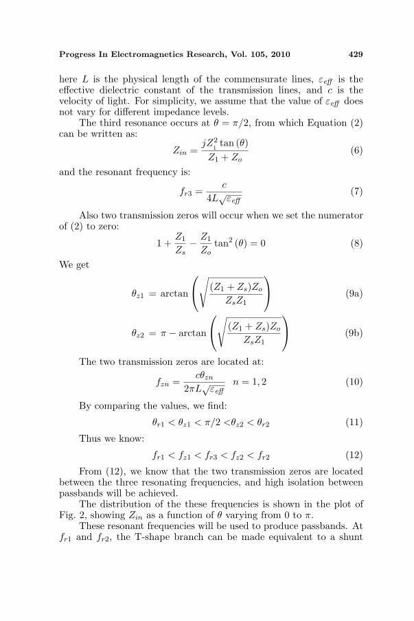
The third resonance occurs at θ = π/2, from which Equation (2)can be written as:
Zin =jZ2
1tan (θ)
Z1 + Zo(6)
and the resonant frequency is:
fr3 =c
4L√
εeff(7)
Also two transmission zeros will occur when we set the numeratorof (2) to zero:
1 +Z1
Zs− Z1
Zotan2 (θ) = 0 (8)
We get
θz1 = arctan
√(Z1 + Zs)Zo
ZsZ1
(9a)
θz2 = π − arctan
√(Z1 + Zs)Zo
ZsZ1
(9b)
The two transmission zeros are located at:
fzn =cθzn
2πL√
εeffn = 1, 2 (10)
By comparing the values, we find:
θr1 < θz1 < π/2 <θz2 < θr2 (11)
Thus we know:
fr1 < fz1 < fr3 < fz2 < fr2 (12)
From (12), we know that the two transmission zeros are locatedbetween the three resonating frequencies, and high isolation betweenpassbands will be achieved.
The distribution of the these frequencies is shown in the plot ofFig. 2, showing Zin as a function of θ varying from 0 to π.
These resonant frequencies will be used to produce passbands. Atfr1 and fr2, the T-shape branch can be made equivalent to a shunt

430 Liu, Dou, and Zhao
parallel resonator with an admittance slope related to the passbandbandwidth. The admittance slope is given by
bn =dBin
dω=
dIm(Yin(ω))dω
|f=frn =dIm(Yin(ω))
d tan(θ)d tan(θ)
dω|f=frn
=d(1/Zin(tan(θ))
d tan(θ)sec2(θ)
π
2ω
∣∣f=frn
=sec2(θ)4Z1fr3
(k1k3 − 3k2k4) + k1k4 tan2(θ) + k2k3 cot2(θ)(k3 − k4 tan2(θ))2
|f=frn
=L√
εeff (1 + k5)2πZ1c
(k1k3 − 3k2k4) + k1k4k5 + k2k3/k5
(k3 − k4k5)2n=1, 2 (13)
where θ can be expressed as:
θ =ωL√
εeff
c=
π
2f
fr3(14)
and:k1 = 1 + Z1/Zo (15a)k2 = Z1/Zs (15b)k3 = 1 + Z1/Zs (15c)k4 = Z1/Zo (15d)
k5 =Z1Zo
Zs(Z1 + Zo)(15e)
We should note that b1 is equal to b2.At fr3, the T-shape branch is equivalent to a short-circuited stub
with the characteristic impedanceZc = Z2
1/(Z1 + Z0) (16)
2.2. Tri-band Filter Design
Traditional bandpass filters can be derived from distributed lowpassprototype filters such as that shown in Fig. 3(a) by using lowpass tobandpass transformations giving the filter of Fig. 3(b) or by usingRichard’s transformation to give the stub filter of Fig. 3(c). Thebandwidths are determined by the admittance slope of each resonator.
For convenience we can set all the J inverters of a distributedprototype lowpass filter to be at the same impedance level, so that
J01 = JN−1,N = Y0 (17)
J12 = J23 = . . . = JN−1,N =
Y0 N is evenY0√
g0gn+1 N is odd (18)
Ca1 = CaN = Y0g0g1 (19)

Progress In Electromagnetics Research, Vol. 105, 2010 431
(a)
(c)
(b)
Figure 3. Lowpass to bandpass transformation. (a) Distributedlowpass prototype filter; (b) Coupled resonator bandpass filter achievedby a lowpass to bandpass transformation; (c) Shunt stub filter achievedby Richard’s transformation.
Ca,k+1 =J2
k,k+1
Ca,kgkgk+1k = 1, 2, . . . , N − 2 (20)
Considering a bandpass filter with a center frequency of f0 anda bandwidth of ∆f , if it is in the form of Fig. 3(b) we will have anadmittance slope for the kth resonator of
bk =2Cak
∆ω=
Cak
π∆f(21)
and the resonator elements are given by
Crk =bk
2and Lrk =
1Crkω
20
(22)
If the bandpass filter is a shunt stub filter as in Fig. 3(c) we mayuse formulas listed on Page 153 of [21] to compute the characteristicimpedance of each short-circuited stub, Zck. In order to have all the J

432 Liu, Dou, and Zhao
inverters at the same impedance level, we need to set the dimensionalparameter h to be
h =g2
g1
(J1,2
Y0g0
)2
(23)
The design of the tri-band filter may be regarded as the designof three bandpass filters simultaneously. We can term the passbandscentered at frequencies fr1, fr2 and fr3 as passbands I, II, and III.The three bandpass filters are derived from one distributive lowpassprototype filter, and thus have the same number of poles and usecommon J inverters.
The tri-mode T-shape branches may be equalized to shunt-resonators with required admittance slopes at fr1, fr2, and λ/4 shortcircuited stub with required characteristic impedance at fr3, hencerealizing the tri-band filter.
If commensurate T-shape branches are used, passbands I and IIwill have the same bandwith because of equal admittance slopes at theresonating frequencies fr1 and fr2. Also the frequency spacing betweenfr1 and fr3 will equal to that between fr2 and fr3. Fig. 4 is the circuitof a 3-pole tri-band filter using three T-shape branches.
To design the parameters of the kth T-shape branch, we need tosolve the following equations:
L√
εeff (1 + k5)2πZ1c
(k1k3 − 3k2k4) + k1k4k5 + k2k3/k5
(k3 − k4k5)2=
Cak
π∆f1,2(24)
Z21
Z1 + Zo= Zck (25)
θr1 = π − θr2 =πfr1
2fr3= arctan
(√Z1Zo
Zs(Z1 + Zo)
)(26)
Figure 4. Circuit topology of a three-pole tri-band filter with threeT-shape branches.

Progress In Electromagnetics Research, Vol. 105, 2010 433
(24) gives the relationship between the admittance slopes ofresonators and the bandwidth for passbands I and II. (25) relates theequivalent characteristic impedances of shunt stubs for passband III,and (26) gives the ratios between the center frequencies.
Hence this is a multi-object problem, and because of itscomplexity, a genetic algorithm routine [23] was used to conduct aglobal search of the circuit parameters for each T-shape branch.
3. DESIGN EXAMPLE
To explain the design procedure a 3-pole tri-band filter design exampleis presented here, commencing from a 3rd order Chebyshev prototypefilter with an in-band ripple of 0.01 dB. The three passbands are600–900MHz, 1350–1650 MHz and 2100–2400 MHz, with the centerfrequencies at 750MHz, 1500MHz and 2250 MHz.
The lumped lowpass prototype filter has element values:
g0 = 1, g1 = g3 = 0.6291, g2 = 0.9702, g4 = 1.
If we set the input and output impedance to be 50 Ω, byusing (17)–(20) we obtain the element values of the distributive lowpassfilter as:
J01 = J12 = J23 = J34 = 1/Z0 = 0.02 s;Ca1 = Ca3 = 0.0126F, Ca2 = 0.0194F.
Using (21), we derive the admittance slopes of the three branchesat fr1, fr2 as
b1 = b3 = 0.01337 (s/GHz), b2 = 0.02054 (s/GHz).
For the 3rd passband, using the formula in [22], the characteristicimpedances of the shunt stubs are:
Zc1 = Zc3 = 16.06Ω and Zc2 = 10.8Ω
Table 1. Circuit parameters of a three-pole tri-band filter usingcommensurate T-shape branches.
Pole order, k 1, 3 2bk of Passband I, II (s/GHz) 0.01337 0.02054
Zck of passband III (Ω) 16.06 10.8Z1 (Ω) 41.1 27.1Zo (Ω) 65.3 40.9Zs (Ω) 30.9 20.1

434 Liu, Dou, and Zhao
Figure 5. Circuit simulationresult of the initial design fora three-pole tri-band filter withthree T-shape branches.
Figure 6. Two-port circuit todetermine the transmission polesof each band by applying weakcapacitive couplings at the twoports.
The circuit parameters obtained by using the genetic algorithmroutine are given in Table 1.
Quarter wavelength transmission lines at fr3, the center frequencyof the three passbands, are used to implement the J inverters thatconnect the three T-shape branches.
A circuit simulation using Ansoft Serenade 8.7 [24] is conductedfor validating the initial design, with the response shown in Fig. 5.
Checking the simulation result of the initial design carefully, wefind that passband I and passband III each have poor return lossperformance at the band edges close to passband II, with some shiftof the required center frequencies. This is because the connecting linesare only narrow-band J inverters at passband III and are not equal toquarter-wave length at passbands I and II.
Figure 6 shows a sub-network, which contains two T-shapebranches connected by a transmission line. Using weak capacitivecouplings at the external ports and conducting a two-port simulation,two transmission poles from S21 plot are obtained, thus determiningthe coupling bandwidth. We may observe the variation of S21 whenthe length of the connecting line changes.
As seen in Fig. 7, a connecting line with a length unequalto a quarter-wave length may still act as a coupling element, butfrequency shift for the two transmission poles are incurred comparedwith the case that uses quarter-wave length line. In this design, theconnecting line (90 at 1.5 GHz) is longer than a quarter-wave length atpassband II but shorter than that at passband I, resulting in downwardfrequency shift at the higher passband and upward frequency shift at

Progress In Electromagnetics Research, Vol. 105, 2010 435
(a) (b)
Figure 7. Compared two-port simulation results of a couplingstructure using connecting lines of different lengths: (a) Passband I;(b) Passband II.
Figure 8. Circuit dimensions of the final design for a three-pole tri-band filter with three T-shape branches integrated inside. W0 = 0.92;W1 = 1.67; W2 = 2.43; W3 = 1.57; W4 = 0.4; W5 = 2.36; W6 = 1.05;S = 28.45; L1 = 31; L2 = 19.92; L3 = 22.95; L4 = 27.03; L5 = 20.04;L6 = 23.13; L7 = 16. (Unit: mm).
the lower passband. There will also be some slight changes givingsome degradation of return loss in addition to inaccurate bandwidthsfor passbands I and II.
In practice, therefore, we need to do some optimization on widthsand lengths of the lines in T-shape branches to tune the resonatingfrequencies and admittance slopes to compensate for these effects.
Figure 8 gives the final circuit of the tri-band filter. It is fabricatedon Rogers 4003C material with a dielectric constant of 3.38 and athickness of 0.4mm. The folded T-shape branches realize the tri-bandfilter in an area no larger than a short-circuited stub filter.
The simulation results and measured results of the tri-band filterare shown in Fig. 9.

436 Liu, Dou, and Zhao
(a) (b)
Figure 9. Comparison between measured and simulated result, of atri-band filter using T-shape branches: (a) Amplituide response; (b)Group delay.
Figure 10. Photograph of thefabricated tri-band filter using T-shape branches.
Figure 11. T-shape branch withnon-commensurate transmissionlines.
We observe that the lowest insertion loss for the three passbands,from the lowest to the highest, are 0.15, 0.5, and 0.7 dB, with returnlosses of better than 15 dB, 18 dB and 10 dB respectively. High isolationof more than 60 dB is achieved between the three passbands. Thereexists some frequency shift between measured and simulated passbandsdue to fabrication tolerances.
The example filter is shown in Fig. 10. Because of the existenceof near-band transmission zeros between the passbands, asymmetricalamplitude response can be observed for passbands I and II.

Progress In Electromagnetics Research, Vol. 105, 2010 437
4. TRI-BAND FILTERS WITH FULLY CONTROLLABLEPASSBANDS
A tri-band filter designed with commensurate T-shape branches hastwo limitations: the frequency spacing between fr1 and fr3 must equalthat between fr2 and fr3, and the 1st and 2nd passbands have the samebandwidth due to their equal admittance slope. To achieve controllablepassbands without such limitations we need to allow the lengths of thethree transmission lines to be different in the T-shape branch to obtainmore design freedom.
We find
Yin =j(tan θ1 + Z1
Zotan θ3 − Z1
Zscot θ2
)
Z1
(1 + Z1
Zstan θ1 · cot θ2 − Z1
Zotan θ1 · tan θ3
) (27)
To achieve three passbands with center frequencies of fr1, fr2, fr3,and bandwidths of ∆f1, ∆f2, ∆f3, the kth T-shape branch will satisfythe following 6 equations:
Yin(frn) = 0 n = 1, 2, 3 (28)
b(frn) =dBin
dω|f=frn =
d(Im(Yin))dω
|f=frn =Cak
π ·∆fnn=1, 2, 3 (29)
Here, we use a finite difference method to calculate b(frn) as:
b(frn)=dBin
dω|f=frn =
d(Im(Yin))dω
|f=frn≈Im(Yin(frn+δ))−Im(Yin(frn))
2πδ(30)
where δ is a small variation of frequency.(28) and (29) are a set of transcendental equations, which can not
be easily solved analytically. Again, a genetic algorithm is used to solvethe equation set to obtain the characteristic impedance and electricallength of each transmission line section in Fig. 4. To speed up theconvergence in solving the multiple-objective problem, we should firstlyeliminate the redundant unknowns by expressing them as functions ofthe other unknowns.
A practical and important issue in realizing a tri-band filter of thistopology is the impedance level of each transmission line, which shouldbe within a realizable range. If the kth T-shape branch has impedancelevels of Z1k, Zsk, Zok and electrical lengths θ1k, θsk, θok, then for thejth T-shape branch, the related parameters can be a good solution ifthey satisfy the following:
Z1k
Z1j=
Zok
Zoj=
Zsk
Zsj=
Caj
Cak(31)
θ1k = θ1j ; θsk = θsj ; θok = θoj (32)

438 Liu, Dou, and Zhao
The maximum impedance ratio (MIR) in a T-shape branch canbe defined as:
Rmax,k =max(Z1k, Zsk, Zok)min(Z1k, Zsk, Zok)
(33)
and the overall maximum impedance ratio of all T-shape branches is:
Rmax,o =max(Z1k, Zsk, Zok)min(Z1k, Zsk, Zok)
· max(Cai|i = 1, 2, . . . , n)min(Cai|i = 1, 2, . . . , n)
(34)
From (31) know that for given center frequencies and bandwidthswe can obtain the same MIR for all the T-shape branches, and it ispossible to tune the impedance level of the kth T-shape branch bychanging the value of Cak. For the lowest Rmax,o, we should set:
Ca1 = Ca2 = . . . = Can (35)
and then:Rmax,o = Rmax (36)
The impedance levels of each connection line are determined bythe values of Ca1, Ca2, Ca3, . . . , Can. The MIR is a key factor indeciding the realizability of a specified tri-band filter. We can setthe bandwidth ratios as: R1 = ∆f2/∆f1 and R2 = ∆f3/∆f1. If thecenter frequencies are given, we may obtain a plot of MIR with respectto the values of R1 and R2. Fig. 12 is a case where the three centerfrequencies are located at 0.85 GHz, 1.8 GHz and 2.25GHz.
If we assume the realizable impedance range of the microstripline to be 13 ∼ 130Ω, the allowable MIR of a T-shape branch mustbe lower than 10. It may be observed from Fig. 12 that MIR is
(a) (b)
Figure 12. Maximum impedance ratio with respect to bandwidthratios: (a) 0.2 ≤ R1 ≤ 1.2; (b), 1.4 ≤ R1 ≤ 2.6.

Progress In Electromagnetics Research, Vol. 105, 2010 439
high when R1 or R2 is low, but in a large value range of R1 andR2 (0.4 ≤ R1 ≤ 2.6∩ 0.4 ≤ R1 ≤ 2.6) the MIR is lower than 10, whichmeans the tri-band filter is realizable without using extremely wide ornarrow transmission lines.
Here we give a design example. For a 3-pole tri-band filter withpassbands of 700–1000, 1650–1950, and 2200–2300MHz, we set:
J01 = J34 = 1/Z0 = 0.02
Then we find:
Ca1 = Ca3 =J2
01g0g1
Z0= 0.0126 F
To achieve the lowest overall MIR, we set:
Ca2 = Ca1 = 0.0126F
Thus:
J12 = J23 =
√Ca1Ca2
g1g2=
Ca1√g1g2
= 0.0161 s
The genetic algorithm routine was used to derive the impedancesand electrical lengths of all T-shape branches, as shown in Table 2.The circuit simulation result of the initial design is shown in Fig. 13,from which we can observe frequency shifting of the passbands andimperfect in-band return loss.
To compensate for the effects incurred by the approximationincurred by the imperfect J inverters, an overall performance
Pole order, k 1, 2, 3
Cak (F) 0.0126
Z1k (Ω) 29.77
θ1k (degree) [email protected]
Zsk (Ω) 14.94
θ2k (degree) [email protected]
Zok (Ω) 105.11
θ3k (degree) [email protected]
Table 2. Circuit parametersof a three-pole tri-band filterusing length-non-commensurateT-shape branches.
Figure 13. Circuit simulationresult of initial design of thetri-band filter with asymmetricpassbands.

440 Liu, Dou, and Zhao
Figure 14. Circuit dimensions of the final design for a three-pole tri-band filter with three T-shape branches integrated inside. W0 = 0.92;W1 = 0.64; W2 = 2.57; W3 = 0.13; W4 = 4.07; W5 = 1.77; W6 = 0.19;W7 = 1.51; S = 29.56; L1 = 29.51; L2 = 8; L3 = 17.21; L4 = 8;L5 = 19.14; L6 = 25.85; L7 = 8; L8 = 16.88; L9 = 13; L10 = 20.95.(Unit: mm).
(a) (b)
Figure 15. Compared results of the tri-band filter with asymmetricpassbands: (a) Amplitude response; (b) Group delay.
Figure 16. Photograph of the tri-band filter using non-commensurateT-shape branches.

Progress In Electromagnetics Research, Vol. 105, 2010 441
optimization is conducted with only the circuit parameters of the T-shape branches being variables. Fig. 14 gives the circuit dimensionsafter optimization.
Comparisons between the circuit simulation and measured resultsare shown in Fig. 15, in which we observe frequency shifting incurred byfabrication tolerances. The lowest insertion loss of the three passbands,from lowest to highest, are 0.5 dB, 1.5 dB and 2.3 dB repectively. Thereturn losses are better than −12 dB.
This design exhibits asymmetric performance in passbandallocation and bandwidths. Fig. 16 shows a photograph of the filter.
Next, some detailed comparison between this work and othertechniques as presented in [3, 17] and [20] are given. As can beseen in Table 3, T-shaped branch tri-band filters gives a greater
Table 3. Performance comparison between the proposed tri-band filterand other techniques.
Solution This work Ref. [3] Ref. [17] Ref. [20]
Technique
Type
Tri-mode
resonator
Dual behavior
Resonator
Tri-section
SIR
Tri-section
SIR
Pole
Number3 2 2 2
Center
Frequencies
(GHz)
0.85/1.8/2.25 1.4/2.3/3.5 1/2.4/3.6 1/2.4/3.6
Bandwidths
(MHz)300/300/100
About
50/200/50
About
50
About
50
Ability
of setting
bandwidths
YesNot
discussedNo No
Impedance
Range (Ω)16.5 ∼ 124 N/A 50 ∼ 93.3 50 ∼ 93.3
Insertion
Loss (dB)0.5/1.5/2.3 2.5/2.5/3 2.2/1.8/1.7 2/1.9/1.7
Isolation
(dB)70/40 50/50 40/30 40/25
Size (mm2) 120 ∗ 4450mm in
length60 ∗ 60 40 ∗ 40
Material
Permittivity3.38 9.9 2.65 2.45

442 Liu, Dou, and Zhao
range of bandwidths, and wideband bandwidths can be easily achievedcompared with tri-section SIR techniques. Also the T-shape branchtechnique can achieve lower insertion loss. Because of the transmissionzeros (there exist N zeros between every two nearest bands of a N -pole tri-band filter), the isolation between bands is much higher thanall the other techniques, taking into account the bandwidths of thepass and stop bands. The relatively larger dimension of the examplefilter is due to the lower permittivity of the PCB material, lower centerfrequencies and higher number of poles. Also it is possible to achievemore compact dimensions using meandered connecting lines. As ashortcoming, the required impedance range of T-shape branch filtersare wider than those in [17] and [20], but are still realizable with currentPCB techniques.
5. CONCLUSIONS
A new tri-mode T-shape branch is introduced and used to design tri-band filters. A theoretical analysis of commensurate T-shape branchesis given with a detailed design procedure, and an example filterfabricated and measured. Good agreement between simulation andmeasurement results has validated the theory. To achieve arbitrarypassbands, non-commensurate T-shape branches are proposed to givemore design freedom, and a genetic algorithm is used. Design examplewith measured results have shown the realizability of arbitrary centerfrequencies and bandwidths. By deriving the three passbands fromone distributive lowpass prototype filter, one needs only to tune theadmittance slope of each resonating mode to control the bandwidths.
ACKNOWLEDGMENT
The authors would like to thank Dr. Ralph Levy for valuable commentsand grammatical improvements, and Dr. Hongfu Meng of SoutheastUniversity for discussions.
REFERENCES
1. Lin, Y.-S., C.-C. Liu, K.-M. Li, and C.-H. Chen, “Designof an LTCC tri-band transceiver module for GPRS mobileapplications,” IEEE Trans. Microw. Theory Tech., Vol. 52, No. 12,2718–2724, Dec. 2004.
2. Mokhtaari, M., J. Bornemana, K. Rambabu, and S. Amari,“Coupling matrix design of dual and triple passband filters,”

Progress In Electromagnetics Research, Vol. 105, 2010 443
IEEE Trans. Microw. Theory Tech., Vol. 54, No. 11, 3940–3945,Nov. 2006.
3. Quendo, C., E. Rius, A. Manchec, Y. Clavet, B. Potelon, J.-F. Favennec, and C. Person, “Planar tri-band filter based on dualbehaviour resonator (DBR),” Proc. Eur. Microw. Conf., 269–272,Oct. 1995.
4. Liu, Y. and W.-B. Dou, “A dual-band filter realized by alternatelyconnecting the main transmission-line with shunt stubs and shuntserial resonators,” IEEE Microw. Wireless Compon. Lett., Vol. 19,No. 5, 296–298, May 2009.
5. Chen, X.-P., K. Wu, and Z.-L. Li, “Dual-band and triple-bandsubstrate integrated waveguide filters with chebyshev and quasi-elliptic responses,” IEEE Trans. Microw. Theory Tech., Vol. 55,No. 12, 2569–2578, Dec. 2007.
6. Zhao, H. and T. J. Cui, “Novel triple-mode resonators using split-ring resonator,” Microw. Opt. Technol. Lett., Vol. 49, No. 12,2918–2922, Dec. 2007.
7. De Paco, P., O. Menendez, and J. Marin, “Dual-bandfilter using non-bianisotropic split-ring resonators,” Progress InElectromagnetics Research Letters, Vol. 13, 51–58, 2010.
8. Wu, G.-L., W. Mu, X.-W. Dai, and Y.-C. Jiao, “Design of noveldual-band bandpass filter with microstrip meander-loop resonatorand CSRR DGS,” Progress In Electromagnetics Research, Vol. 78,17–24, 2008.
9. Wang, X.-H. and B.-Z. Wang, “Compact broadband dual-bandbandpass filters using slotted ground structures,” Progress InElectromagnetics Research, Vol. 82, 151–166, 2008.
10. Wu, M.-S., Y.-Z. Chueh, J.-C. Yeh, and S.-G. Mao, “Synthesis oftriple-band and quad-band bandpass filters using lumped-elementcoplanar waveguide resonators,” Progress In ElectromagneticsResearch B, Vol. 13, 433–451, 2009.
11. Chen, F. C. and Q. X. Chu, “Tri-band bandpass filters usingstub loaded resonators,” Electron. Lett., Vol. 44, No. 12, 747–749,Jun. 2008.
12. Lin, W.-J., C.-S. Chang, J.-Y. Li, D.-B. Lin, L.-S. Chen, andM.-P. Houng, “A new approach of dual-band filters by steppedimpedance simplified cascaded quadruplet resonators with slotcoupling,” Progress In Electromagnetics Research Letters, Vol. 9,19–28, 2009.
13. Chen, C. F., T. Y. Huang, and R. B. Wu, “Design of dual-and triple-passband filters using alternately cascaded multiband

444 Liu, Dou, and Zhao
resonators,” IEEE Trans. Microw. Theory Tech., Vol. 54, No. 9,3550–3558, Sep. 2006.
14. Lee, C. H., C. I. G. Hsu, and H. K. Jhuang, “Design of a new tri-band microstrip BPF using combined quarter- wavelength SIRs,”IEEE Microw. Wireless Compon. Lett., Vol. 16, No. 11, 594–596,Nov. 2006.
15. Hsu, C.-I. G., C.-H. Lee, and H.-K. Jhuang, “Design of a novelquadband microstrip BPF using quarter-wavelength stepped-impedance resonators,” Microw. J., Vol. 50, No. 2, 102–112,Feb. 2007.
16. Chen, F. C. and Q. X. Chu, “Design of compact tri-band bandpassfilters using assembled resonators,” IEEE Trans. Microw. TheoryTech., Vol. 57, No. 1, 165–171, Jan. 2009.
17. Lin, X. M. and Q. X. Chu, “Design of triple-band bandpasfilter using tri-section stepped-impedance resonators,” Proc. Int.Microw. Millimeter Wave Tech. Conf., 798–800, Guilin, China,Apr. 2007.
18. Chen, Y.-C., Y.-H. Shieh, C.-H. Her, and C.-I. G. Hsu, “Tri-bandmicrostrip BPF design using tri-section SIRs,” IEEE AP-S Int.Symp. Dig., 3113–3116, Jun. 2007.
19. Hsu, C.-I. G., C.-H. Lee, and Y.-H. Hsieh, “Tri-band bandpassfilter with sharp passband skirts designed using tri-section SIRs,”IEEE Microw. Wireless Compon. Lett., Vol. 18, No. 1, 19–21,Jan. 2008.
20. Chu, Q. X. and X. M. Lin, “Advanced triple-band bandpass filterusing tri-section SIR,” Electron. Lett., Vol. 44, No. 4, 295–296,Feb. 2008.
21. Ma, Z., T. Shimizu, Y. Kobayashi, T. Anada, and G. Hagiwara,“Novel compact dual-band bandpass filters using compositeresonators to obtain separately controllable passbands,” 2006Asia-Pacific Microwave Conference Proceedings, Vol. 3, 1814–1817, FR4B-4, Dec. 2006.
22. Hong, J.-S. and M. J. Lancaster, Microstrip Filter forRF/Microwave Applications, Wiley, New York, 2001.
23. Holland, J. H., Adaption in Natural and Artificial Systems, MITPress, Cambridge, MA, USA, 1992.
24. Ansoft Serenade 8.7, Ansoft Corporation.