one-step synthesis of magnetic zeolite from zinc slag and
TRANSCRIPT
One-Step Synthesis of Magnetic Zeolite from Zinc Slag and CirculatingFluidized Bed Fly Ash for Degradation of Dye Wastewater
Zhichao Han, Yaojun Zhang* and Panyang He
College of Materials Science and Engineering, Xi’an University of Architecture and Technology, Xi’an, 710055, China*Corresponding Author: Yaojun Zhang. Email: [email protected]
Received: 05 December 2019; Accepted: 13 February 2020
Abstract: In this study, a magnetic P zeolite was directly synthesized by utiliza-tion of industrial solid wastes of zinc slag (ZS) and circulating fluidized bed flyash (CFBFA) via one-step hydrothermal method. The effects of differentCFBFA/ZS ratios and hydrothermal times on the as-synthesized zeolite wereinvestigated. The X-ray diffraction (XRD) and vibrating sample magnetometer(VSM) results indicated that the magnetic P zeolite possessed well-definedcrystals and superparamagnetism. The as-prepared zeolite was employed as aFenton-like solid catalyst for degradation of direct green B dye wastewater. Itwas discovered that the magnetic P zeolite took the advantage of rapid separationand efficient recovery under the external magnets in a solid-liquid reaction. Theeffects of the solution pH, the catalyst dosage, and the H2O2 concentration onthe degradation rate of direct green B dye wastewater were studied systematically.The results showed that the highest degradation of 96.3% was obtained and themagnetic P zeolite showed excellent stability after four cycles. Therefore, themagnetic P zeolite derived from industrial solid wastes had a potential applicationin wastewater treatment.
Keywords: Magnetic zeolite; solid wastes; Fenton-like reaction; dye degradation
1 Introduction
Zeolite, a type of aluminosilicate material with regular channels and unique crystal structure, hasbeen widely used in the fields of petrochemical industry, fine chemical industry and environmentalprotection due to its excellent ion exchange, catalysis and adsorption properties [1,2]. However, thesynthesized zeolites are usually solid powders which are difficult to be separated in the solid-liquidsystem so that the wide applications of zeolite powders have been limited. Magnetic zeolite powdershave the advantages of easy separation and recycling by use of the magnetic technology, and becomea research hotspot in the water treatment. Yamaura et al. [3,4] reported that the hydroxyl sodalite wassynthesized by the hydrothermal reaction of fly ash and NaOH solution at 100°C for 24 h, and thenthe magnetic composite was obtained by blending of hydroxyl sodalite with magnetic Fe3O4 by amass ratio of 3:1 in aqueous solution. Anunziata et al. [5] synthesized a magnetic Fen+-ZSM-11zeolite by the incipient wetness impregnation of FeSO4•7H2O and Fe(NO3)3•9H2O salt solutions onthe surface of NH4-ZSM-11 zeolite, and then heated at 500°C for 10 h under nitrogen atmosphere and
This work is licensed under a Creative Commons Attribution 4.0 International License, whichpermits unrestricted use, distribution, and reproduction in any medium, provided the originalwork is properly cited.
Journal of Renewable MaterialsDOI:10.32604/jrm.2020.09351
Article
echT PressScience

calcined in air at 500°C for 12 h. Cao et al. [6] reported that some pure chemical reagents were mixed at amolar ratio of Na2O:Al2O3:SiO2:H2O = 3:1:2.3:185, and then blended with magnetic Fe3O4 to get amixture which was heated at 95°C for 6 h to obtain a magnetic P-type zeolite.
As mentioned above, the magnetic zeolites are usually achieved by addition of magnetic oxide into theas-synthesized zeolites, in which two or more steps are required in the preparation of magnetic zeolites.Recently, Belviso et al. [7] reported that a mixture of waste materials (fly ash and red mud) and NaOHat a mass ratio of 1:1.2 was fused at 600°C for 12 h, and then the molten material was mixed withdistilled water which was incubated at 25–40°C for 4 days to acquire a mixture of A-, X- and ZK-5-type magnetic zeolites without the addition of iron oxide magnetic nanoparticles.
Zinc slag (ZS) is an industrial solid waste discharged from the zinc smelting process. The ChinaReport Hall [8] reported that the output of zinc metal was 5.681 million tons in 2018. The discharge ofzinc slag in China was about 5.45 million tons, and its historical stockpiling volume exceeded to 100million tons according to the production of each ton of zinc metal to discharge 0.96 tons of zinc slag[9]. Circulating fluidized bed boiler (800–900°C) is a new clean combustion technology of highefficiency and low pollution. It is reported that the annual discharge of circulating fluidized bed fly ash(CFBFA) is about 90 million tons and gradually increases year by year [10]. The vast accumulation ofZS and CFBFA has already caused wasting of resources, serious environmental pollution, and hugeeconomic losses [11,12]. This paper takes a mixture of ZS and CFBFA as silicon and aluminumsources, and utilizes the magnetic component containing in the ZS and CFBFA to directly synthesizemagnetic P zeolite without addition of magnetic oxide via one-step hydrothermal reaction. Theutilization of industrial solid wastes as precursors for preparation of zeolites can not only reduce theenvironmental pressure, but also obtain high value-added magnetic zeolite. Moreover, the magnetic Pzeolite synthesized from ZS and CFBFA is employed as a Fenton-like catalyst for the simulateddegradation of printing and dyeing wastewater. It can be a new approach to achieve the dual purpose of“waste control by waste”. To our knowledge, the study on utilization of ZS and CFBFA as precursorsfor the direct synthesis of magnetic P zeolite by one-step hydrothermal reaction has not yet beenreported in the current literatures.
2 Materials and Methods
2.1 MaterialsThe zinc slag (ZS) was provided by Zinc Smelting Plant of Shangluo, Shaanxi province of China and the
circulating fluidized bed fly ash (CFBFA) was from Shenhua Junggar Energy Corporation in Junggar, InnerMongolia of China. The main chemical components of ZS and CFBFAwere measured by the weight percentusing X-ray fluorescence (XRF) and listed in Tab. 1. The sodium hydroxide (A. R.) was purchased fromXi’an Chemical Reagent Company. The water is deionized water.
2.2 Synthesis of Magnetic ZeoliteThe ZS, CFBFA, NaOH and water at the mass ratio of 0.66:1:0.73:15 were weighed respectively. The
ZS and CFBFAwere thoroughly blended to form a mixture which was poured into 1.2 mol/L NaOH solutionand stirred for 2 min to become homogeneous slurry, and then the slurry was placed into a 200 mL of
Table 1: Chemical composition of CFBFA and ZS
Sample CaO SiO2 Al2O3 Fe2O3 MgO Na2O K2O SO3 TiO2
CFBFA 2.87 35.14 45.35 2.61 0.23 0.08 0.34 0.54 1.82
ZS 9.10 16.79 8.94 39.68 2.32 1.00 4.00 0.42 –
406 JRM, 2020, vol.8, no.4
autoclave to carry out the hydrothermal reaction at 105°C for 12 h, 24 h, 48 h and 60 h, respectively. Thedifferent magnetic P zeolite samples were obtained after filtration, washing and drying. The differentratios of CFBFA and ZS were shown in Tab. 2.
2.3 Characterization of Magnetic ZeolitesElemental analysis of the sample was carried out on an X-ray fluorescence spectrometer. The X-ray
diffraction (XRD) patterns of the samples were recorded on an X-ray diffractometer using CuKα (λ =1.54056 Å) operated at 40 kV and 40 mA with a scanning rate of 10°/min from 2θ range of 5–70°. Themicro-morphologies were captured by a FEI Quanta 200 scanning electron microscopy (SEM) equippedwith energy dispersive X-ray spectroscopy (EDS). Fourier-transform infrared (FT-IR) spectra of sampleswere detected on a Nicolet 5700 FT-IR spectrophotometer in the range of 400 to 4000 cm−1 using a KBrdisk. The magnetization hysteresis loop of sample was determined on a VSM-7404 type vibrating samplemagnetometer.
2.4 Treatment of Printing and Dyeing WastewaterThe catalytic activities of magnetic P zeolites were evaluated by simulated degradation of printing and
dyeing wastewater of direct green B dye in Fenton-like reaction. The initial absorbance (A0) of direct green Bdye (the corresponding concentration (C0)) was measured at the maximum absorption wavelength of 628 nm.Put 100 mL of direct green B dye solution with concentration of 40 mg/L into a beaker, and then add certainamount of H2O2 into the solution. The pH value of solution was adjusted by addition of 0.1 M HCl or 0.05 MNaOH. After a certain amount of magnetic P zeolite was introduced to the solution containing direct green Bdye, the solution was stirred at 200 rpm for certain time. The supernatant solution was obtained by centrifugalseparation at 10 min intervals and was monitored the absorbance (At) (the corresponding concentration (Ct)).The degradation rate (DR) of dye was calculated using Eq. (1). Where DR is the degradation rate of directgreen B dye, A0 (C0) and At (Ct) are the absorbance (concentration) of direct green B dye solution at originaland t time, respectively.
DR %ð Þ ¼ ðC0�CtÞ =C0 � 100% ¼ ðA0 �AtÞ =A0 � 100% (1)
3 Results and Discussion
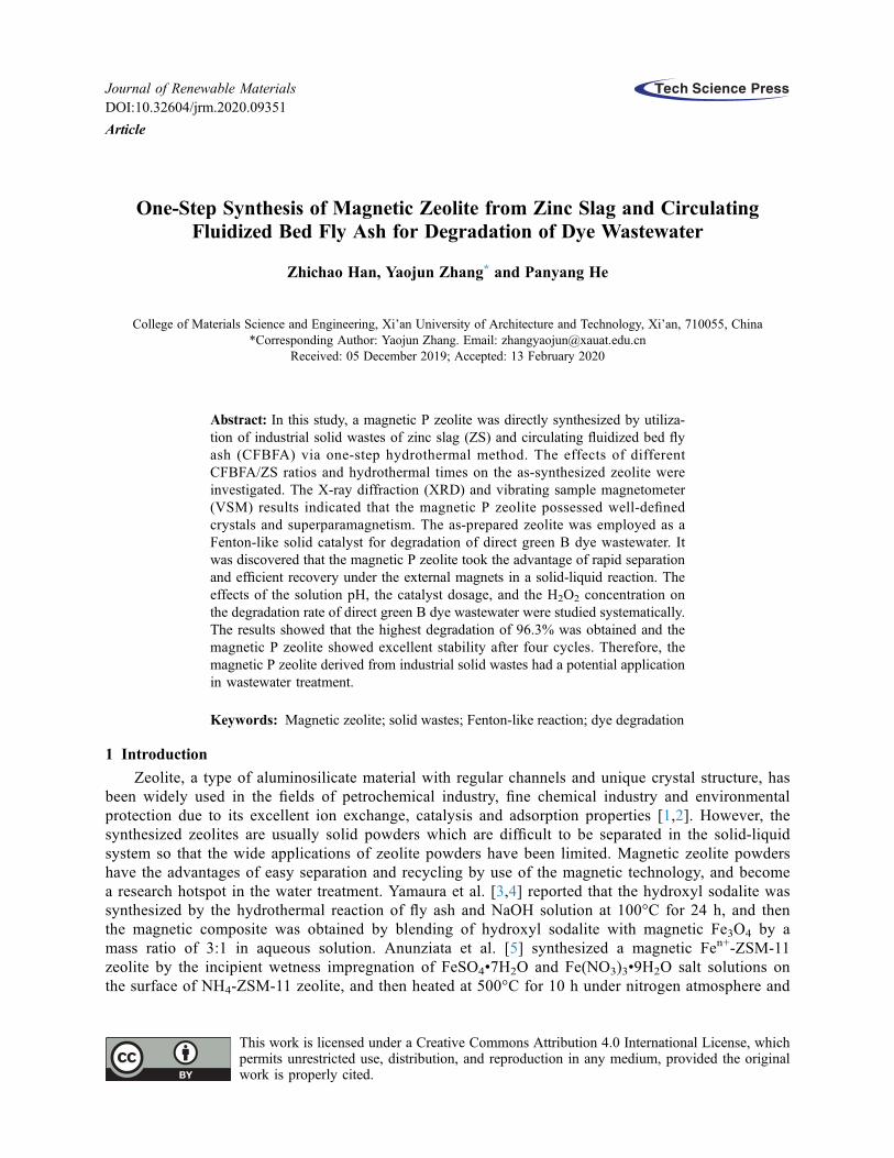
3.1 Microstructure of Magnetic P ZeoliteFig. 1 shows the XRD patterns of samples. From the Fig. 1a, it can be found that the CFBFA sample
displays several diffraction peaks at 20.85°, 26.74° as well as at 16.28°, 26.47°, 33.29°, 40.90°, 45.63°,67.39° belonging to quartz and mullite phases, respectively, and the broad diffuse hump in the range of15°–35° is assigned to be amorphous silica. In the pattern of ZS, there are the characteristic peaks ofmagnetite at 30.1°, 43.1° and 53.5° (JCPDS No. 74–0748), besides the quartz and mullite phases. Fig. 1bpresents the XRD patterns of samples synthesized from the different ratios of CFBFA to ZS by theweight percent which are shown in Tab. 2. For the CZ(20/80) sample, some peaks occur at 12.42°,
Table 2: Composition of CFBFA and ZS mixture
Sample CFBFA (wt%) ZS (wt%) Si/Al
CZ(20/80)* 20 80 1.07
CZ(60/40)* 60 40 0.76
CZ(80/20)* 80 20 0.70* The samples of CZ(80/20), CZ(60/40) and CZ(20/80) were synthesized at the different ratios of CFBFAand ZS by the weight percent (The acronym of CZ is from the first letters both CFBFA and ZS).
JRM, 2020, vol.8, no.4 407

17.63°, 21.61°, 28.04°, 33.35° and 46.02° corresponding to P zeolite (JCPDS No.44–0052), and othersappear at 30.1°, 43.1° and 53.5° to be the magnetite (Fe3O4) (JCPDS No. 74–0748), indicating that themagnetic P zeolite is successfully synthesized by one-step hydrothermal reaction. When the weightpercent of CFBFA is gradually increasing from 20 to 80 in the different samples, it is clear that the peak
10 20 30 40 50 60 70 80
Inte
nsity
(a.
u.)
2θ (°)
2θ (°)
2θ (°)
ZS
CFBFA
a
a
a
a
b
bb
bb b
bb b
b b
c c
a:Quarteb:Mulltec:Magnetite
c
(a)
10 20 30 40 50 60 70
0
1000
2000
0
1000
2000
0100020003000
Zeolite P, (Na) JCPDS#44-0052
∗ CZ(20/80)
∗
* Magnetite
∗ CZ(80/20)
∗
∗
∗
∗
∗
∗
Inte
nsity
(C
PS)
(b)
CZ(60/40)
015003000
010002000
020004000
10 20 30 40 50 60 70
020004000
24h
12h
Zeolite P, (Na) JCPDS#44-0052
∗
∗
∗
∗
∗
∗
∗
∗
∗
∗
∗
60h(c)
∗
* Magnetite
Inte
nsity
(C
PS)
48h
Figure 1: XRD patterns of samples. (a) Rawmaterials of CFBFA and ZS, (b) Samples of CZ(80/20), CZ(60/40)and CZ(20/80) synthesized from the different ratios of CFBFA to ZS by the weight percent, and (c) Crystallizationtimes of CZ(60/40) from 12 h, 24 h, 48 h to 60 h, respectively
408 JRM, 2020, vol.8, no.4
intensities of P zeolite display a trend of increasing first, but then decreasing. The pattern of CZ(60/40) has aset of the highest intensity of peaks. Fig. 1c shows the patterns of the CZ(60/40) sample at differentcrystallization times from 12 h, 24 h, 48 h to 60 h. It can be seen that the peak intensities of P zeolite arerapidly increasing from 12 h to 48 h, and then approach to constant value at 60 h, demonstrating that theoptimal mass ratio of ZS:CFBFA:NaOH:H2O = 0.66:1:0.73:15, and the hydrothermal time of 48 h arecritical for the synthesis of magnetic P zeolite.
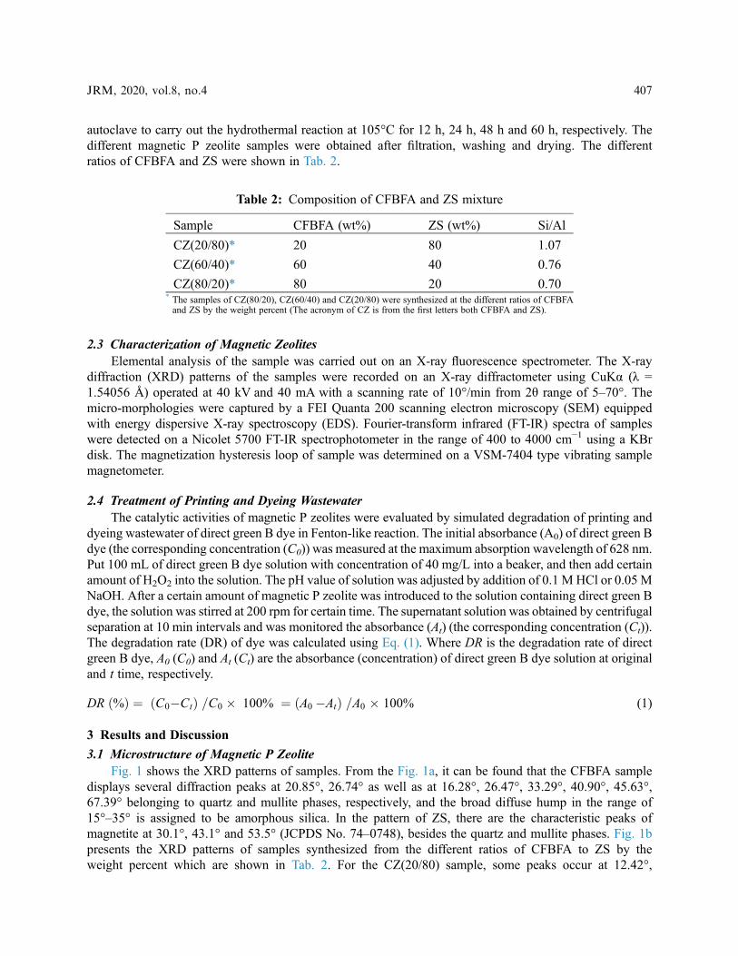
Fig. 2 displays SEM micrographs of the samples. The CFBFA shows the irregular particles with sizeabout 30 μm in Fig. 2a, and ZS also exhibits an irregular morphology with size about 20 μm in Fig. 2b.From Fig. 2c–2f, a kind of spherical crystals are obtained and identified as P zeolite, which are similarto those reported in previous literatures [13,14]. In addition, it is revealed that the increasing ofcrystallization time from 12 h to 60 h is beneficial to the formation of magnetic P zeolite sphericalparticles with mean size about 2 μm. In comparison with CFBFA and ZS, the magnetic P zeolites showrelatively much smaller and more uniform spherical particles. The previous studies also reported thatthe particle size of P zeolite is about 2–10 μm [13,14]. During the hydrothermal treatment, the siliconand aluminum species in CFBFA and ZS are dissolved in NaOH solution to form [SiO4]
4− and [AlO4]5−
tetrahedrons which are the primary building block of zeolite, and then the micro-crystals of P zeoliteare obtained under the template agent of Na+ ions [15]. Furthermore, the EDS result indicates that thepresence of Fe, Si, Al and O in the P zeolites. SEM and EDS results further demonstrate the creation ofmagnetic P zeolite.
Figure 2: SEM micrographs of (a) CFBFA, (b) ZS, (c–f) crystallization times of magnetic P zeolite sample(CZ(60/40)) from 12 h, 24 h, 48 h to 60 h as well as the element analysis of EDS
JRM, 2020, vol.8, no.4 409
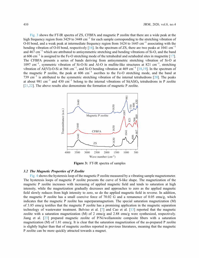
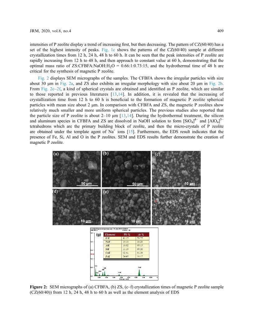
Fig. 3 shows the FT-IR spectra of ZS, CFBFA and magnetic P zeolite that there are a wide peak at thehigh frequency region from 3429 to 3448 cm−1 for each sample corresponding to the stretching vibration ofO-H bond, and a weak peak at intermediate frequency region from 1624 to 1645 cm−1 associating with thebending vibration of O-H bond, respectively [16]. In the spectrum of ZS, there are two peaks at 1041 cm−1
and 467 cm−1 which are attributed to antisymmetric stretching and bending vibrations of Si-O, and the bandat 606 cm−1 is assigned to the Fe-O stretching mode of the tetrahedral and octahedral sites in magnetite [17].The CFBFA presents a series of bands deriving from antisymmetric stretching vibration of Si-O at1097 cm−1, symmetric vibration of Si-O-Si and Al-O in mullite-like structures at 821 cm−1, stretchingvibration of Al(VI)-O-Si at 566 cm−1, and Si-O bending vibration at 469 cm−1 [18,19]. In the spectrum ofthe magnetic P zeolite, the peak at 606 cm−1 ascribes to the Fe-O stretching mode, and the band at739 cm−1 is attributed to the symmetric stretching vibration of the internal tetrahedrons [20]. The peaksat about 981 cm−1 and 430 cm−1 belong to the internal vibrations of Si(Al)O4 tetrahedrons in P zeolite[21,22]. The above results also demonstrate the formation of magnetic P zeolite.
3.2 The Magnetic Properties of P ZeoliteFig. 4 shows the hysteresis loop of the magnetic P zeolite measured by a vibrating sample magnetometer.
The hysteresis loops of magnetic P zeolite presents the curve of S-like shape. The magnetization of themagnetic P zeolite increases with increasing of applied magnetic field and tends to saturation at highintensity, while the magnetization gradually decreases and approaches to zero as the applied magneticfield slowly reduces from high intensity to zero, so do the applied magnetic field in reverse. In addition,the magnetic P zeolite has a small coercive force of 70.02 G and a remanence of 0.05 emu/g, whichindicates that the magnetic P zeolite has superparamagnetism. The special saturation magnetization (M)of 3.85 emu/g testifies that the magnetic P zeolite has a promising application in the magnetic separationtechnology of wastewater treatment. Belviso et al. [7] and Cao et al. [13] reported that the magneticzeolite with a saturation magnetization (M) of 2 emu/g and 2.88 emu/g were synthesized, respectively.Jiang et al. [23] prepared magnetic zeolite of P/Ni/wollastonite composite fibers with a saturationmagnetization (M) of 1.81 emu/g. It is clear that the saturation magnetization of the as-prepared P zeoliteis slightly higher than that of magnetic zeolites reported in previous literatures, meaning that the magneticP zeolite can be more quickly attracted towards a magnet.
4000 3500 3000 2500 2000 1500 1000 500
Tra
nsm
ittan
ce (
a.u.
)
Wave number (cm-1)
3440
1630
1041 467
3440
1630
1097
821
566 46
9
3440
1630
981
739 60
6 430
CFBFA
ZS
Magnetic P zeolite
606
Figure 3: FT-IR spectra of samples
410 JRM, 2020, vol.8, no.4

3.3 Degradation of WastewaterThe magnetic P zeolite is used as a solid catalyst for the degradation of direct green B dye wastewater in
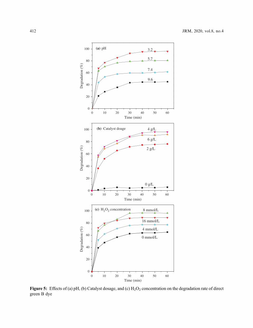
Fenton-like reaction. The effects of the pH of solution, the dosage of catalyst, and the H2O2 concentration onthe degradation rate of direct green B dye wastewater are studied through single factor experiments to obtainthe optimal parameters as shown in Fig. 5.
Fig. 5a shows that the influence of the solution pH from 3.2 to 9.6 on the degradation of direct green Bdye when the catalyst dosage of magnetic P zeolite is 2 g/L and the concentration of H2O2 is 4 mmol/L. It isfound that the degradation rate rapidly reduces from 95.9% to 45.1% as the solution pH increases from 3.2 to9.6 due to the decomposition of H2O2 into H2O and O2 under alkaline condition [24]. Much lower pH is easyto cause the corrosion of equipment, thus, the optimal initial pH is about 3.2. Fig. 5b displays that the effect ofthe catalyst dosage from zero to 6.0 g/L on the degradation of direct green B dye under the certain conditions,for instance, solution pH 3.2 and H2O2 concentration of 4 mmol/L. The degradation rate of direct green B dyeis ascend first from 5.5% (without catalyst) to 94.2% (4.0 g/L catalyst), and then descend from 94.2% to91.6% (6.0 g/L catalyst) due to the fact that the catalyst is prone to aggregate into lump in the case ofcatalyst excess. Therefore, the optimum catalyst dosage is about 4.0 g/L. Fig. 5c shows the influence ofH2O2 concentration on degradation of direct green B dye under the constant pH 3.2 and catalyst dosageof 4.0 g/L. The degradation rate of direct green B dye increases from 65.1% to 96.3% with the increasingof H2O2 concentration from 0 to 8 mmol/L, while the degradation rate declines to 85% as theconcentration of H2O2 rises to 16 mmol/L, suggesting that excessive H2O2 traps hydroxyl radical (∙OH)to generate peroxy radical (HO2∙) with lower redox potential than hydroxyl radical (∙OH) so as todecrease the degradation rate of dye [25]. Hence, the optimal H2O2 concentration is 8 mmol/L. It candraw an optimized reaction condition from Fig. 5. When the initial pH is about 3.2, the H2O2
concentration is about 8 mmol/L, and the magnetic P zeolite catalyst dosage is about 4.0 g/L, there is thehighest degradation rate of 96.3% for the direct green B dye over the magnetic P zeolite catalyst.
Fig. 6 shows the UV-vis spectra of direct green B dye before and after degradation over the magneticP zeolite. The spectrum of direct green B dye presents three main characteristic absorption peaks at thewavelengths of 208 nm, 372 nm, and 628 nm. The strongest peak at 628 nm is assigned to be theabsorption of azo chromophore, while the peaks at 208 nm and 372 nm are related to the absorptions ofE2 and the naphthalene ring structure [26,27]. After degradation reaction, the peaks both 372 nm and 628nm almost disappear, demonstrating that the azo chromophore and the naphthalene ring structure are
-15.0k -10.0k -5.0k 0.0 5.0k 10.0k 15.0k
-4
-3
-2
-1
0
1
2
3
4
-1k -800 -400 0 400 800 1k
-2
-1
0
1
2
M (
emu/
g)
M (
emu/
g)
Field (G)
Figure 4: The hysteresis loop of the magnetic P zeolite
JRM, 2020, vol.8, no.4 411
0 10 20 30 40 50 600
20
40
60
80
100
Deg
rada
tion
(%)
Time (min)
9.6
7.4
5.7
3.2(a) pH
0 10 20 30 40 50 600
20
40
60
80
100
0 g/L
2 g/L
6 g/L
4 g/L
Deg
rada
tion
(%)
Time (min)
(b) Catalyst doage
0 10 20 30 40 50 600
20
40
60
80
100
16 mmol/L
4 mmol/L
0 mmol/L
Deg
rada
tion
(%)
Time (min)
8 mmol/L(c) H2O2 concentration
Figure 5: Effects of (a) pH, (b) Catalyst dosage, and (c) H2O2 concentration on the degradation rate of directgreen B dye
412 JRM, 2020, vol.8, no.4

200 300 400 500 600 700 800-0.2
0.0
0.2
0.4
0.6
0.8
1.0
1.2
Abs
orba
nce
Wavelength (nm)
before
after
628 nm372 nm
208 nm
Figure 6: UV-vis spectra of direct green B dye before and after degradations treatment over magnetic P zeolite
1 2 3 40
20
40
60
80
100
Deg
rada
tion
(%)
Cycle times
(a)
10 20 30 40 50 60 70
Inte
nsity
(a.
u.)
2θ (°)
Before reaction
After reaction
(b)
Figure 7: Stability of magnetic P zeolite of (a) cycle times, and (b) XRD patterns before and afterdegradation of direct green B dye
JRM, 2020, vol.8, no.4 413
broken down to form the small molecule products, like phenol and aminobenzene which possess anabsorption peak at 208 nm identified by high performance liquid chromatography-electrospray ionization-mass spectrometer (HPLC-ESI-MS) and gas chromatography-mass spectrometer (GC-MS) [28].
3.4 Stability of Magnetic P ZeoliteThe stability of magnetic P zeolite is evaluated through four cycles under the optimal conditions as
shown in Fig. 7. The degradation rate of direct green B dye decreases by 9.3% from initial 96.3 to 87%after four cycles, implying that the magnetic P zeolite still remains excellent catalytic activity in Fig. 7a.The XRD patterns of the magnetic P zeolite before and after degradations are almost same, indicatingthat the magnetic P zeolite has excellent stability as shown in Fig. 7b.
4 Conclusions
In this study, a magnetic P zeolite was directly synthesized by one-step hydrothermal method by use ofindustrial wastes of zinc slag and circulating fluidized bed fly ash. The magnetic P zeolite possessedsuperparamagnetism, a small coercive force of 70.02 G, a remanence of 0.05 emu/g, and a saturationmagnetization of 3.85 emu/g. In addition, the magnetic P zeolite as a Fenton-like catalyst for dyewastewater treatment showed excellently catalytic degradation activity and high stability. The degradationrate of direct green B dye over the magnetic P zeolite catalyst approached to 96.3% under the conditionsof initial pH of 3.2, H2O2 concentration of 8 mmol/L, and catalyst dosage of 4.0 g/L. The as-synthesizedmagnetic P zeolite from both circulating fluidized bed fly ash and zinc slag realized the dual goal of“waste control by waste”, in which not only the industrial solid waste could be effectively reused, butalso the magnetic P zeolite could be used as the catalyst for the treatment of dye wastewater in Fenton-like reaction.
Acknowledgement: This study was financially supported by the National Natural Science Foundation ofChina (No. 21676209), Key Research Development Project of Shaanxi Province (No. 2019GY-137) andthe Cultivating Fund of Excellent Doctorate Thesis of Xi’an University of Architecture and Technology(No. 6040318008).
Funding Statement: The author(s) received no specific funding for this study.
Conflicts of Interest: The authors declare that they have no conflicts of interest to report regarding thepresent study.
References1. Li, Y., Yu, J. (2014). New stories of zeolite structures: their descriptions, determinations, predictions, and
evaluations. Chemical Reviews, 114(14), 7268–7316. DOI 10.1021/cr500010r.
2. Li, Y., Li, L., Yu, J. H. (2017). Applications of zeolites in sustainable chemistry. Chem, 3(6), 928–949. DOI10.1016/j.chempr.2017.10.009.
3. Yamaura, M., Fungaro, D. A. (2013). Synthesis and characterization of magnetic adsorbent prepared by magnetitenanoparticles and zeolite from coal fly ash. Journal of Material Science, 48(14), 5093–5101. DOI 10.1007/s10853-013-7297-6.
4. Fungaro, D. A., Yamaura, M., Craesmeyer, G. R. (2012). Removal from aqueous solution by zeolite from fly ash-iron oxide magnetic nanocomposite. International Review of Chemical Engineering, 4(3), 353–358.
5. Anunziata, O. A., Costa, M. G., Beltramone, A. R. (2006). Fe-ZSM-11 magnetic properties: its relation with thecatalytic activity for NOx SCR with iso-butane and O2. Applied Catalysis A: General, 307(2), 263–269. DOI10.1016/j.apcata.2006.03.053.
414 JRM, 2020, vol.8, no.4
6. Cao, J. L., Fu, R., Liu, X., Tan, C. Y. (2007). Synthesis and characterization of P zeolite with Fe3O4 core. ChineseJournal of Inorganic Chemistry, 23(12), 2065–2071.
7. Belviso, C., Agostinelli, E., Belviso, S., Cavalcante, F., Pascucci, S. et al. (2015). Synthesis of magnetic zeolite atlow temperature using a waste material mixture: fly ash and red mud. Microporous and Mesoporous Materials,202, 208–216. DOI 10.1016/j.micromeso.2014.09.059.
8. The China Report Hall. (2019). Statistical analysis of national zinc production from January to December 2018.http://www.chinabgao.com/chanliang/284778.html.
9. Hao, X. P., Han, J. W., Gao, Z. Q., Li, G. T. (2017). Comprehensive utilization of zinc smelting slag. InorganicChemicals Industry, 49(7), 57–60.
10. Qiu, R., Cheng, F., Huang, H. (2017). Removal of Cd2+ from aqueous solution using hydrothermally modifiedcirculating fluidized bed fly ash resulting from coal gangue power plant. Journal of Cleaner Production, 172,1918–1927. DOI 10.1016/j.jclepro.2017.11.236.
11. He, P. Y., Zhang, Y. J., Chen, H., Han, Z. C., Liu, L. C. (2019). One-step synthesis of rod-shaped phillipsite usingcirculating fluidized bed fly ash and its application for removal heavy metal. Ferroelectrics, 547(1), 51–58. DOI10.1080/00150193.2019.1592483.
12. Chen, X., Gao, J., Yan, Y., Liu, Y. (2017). Investigation of expansion properties of cement paste with circulatingfluidized bed fly ash. Construction and Building Materials, 157, 1154–1162. DOI 10.1016/j.conbuildmat.2017.08.159.
13. Cao, J. L., Liu, X. W., Fu, R., Tan, Z. Y. (2008). Magnetic P zeolites: synthesis, characterization and the behavior inpotassium extraction from seawater. Separation and Purification Technology, 63(1), 92–100. DOI 10.1016/j.seppur.2008.04.015.
14. Sathupunya, M., Gulari, E., Wongkasemjit, S. (2002). ANA and GIS zeolite synthesis directly from alumatraneand silatrane by sol-gel process and microwave technique. Journal of the European Ceramic Society, 22(13),2305–2314. DOI 10.1016/S0955-2219(02)00042-0.
15. Bohra, S., Kundu, D., Naskar, M. K. (2013). Synthesis of cashew nut-like zeolite NaP powders using agro-wastematerial as silica source. Materials Letters, 106, 182–185. DOI 10.1016/j.matlet.2013.04.080.
16. He, P. Y., Zhang, Y. J., Chen, H., Han, Z. C., Liu, L. C. (2019). Low-energy synthesis of kaliophilite catalyst fromcirculating fluidized bed fly ash for biodiesel production. Fuel, 257, 116041. DOI 10.1016/j.fuel.2019.116041.
17. Zhang, M. J., Wang, M. L., Zhang, M. X., Maimaitiming, A., Pang, L. J. et al. (2018). Fe3O4 nanowire arrays onflexible polypropylene substrates for UV and magnetic sensing. ACS Applied Nano Materials, 1(10), 5742–5752.DOI 10.1021/acsanm.8b01386.
18. Liu, Y., Yan, C. J., Zhang, Z. H., Wang, H. Q., Zhou, S. et al. (2016). A comparative study on fly ash, geopolymerand faujasite block for Pb removal from aqueous solution. Fuel, 185, 181–189. DOI 10.1016/j.fuel.2016.07.116.
19. Guo, C., Zou, J., Wei, C., Jiang, Y. (2013). Comparative study on extracting alumina from circulating fluidized-bedand pulverized-coal fly ashes through salt activation. Energy & Fuels, 27(12), 7868–7875. DOI 10.1021/ef401659e.
20. Liu, Y., Yan, C. J., Zhao, J. J., Zhang, Z. H., Wang, H. Q. et al. (2018). Synthesis of zeolite P1 from fly ash undersolvent-free conditions for ammonium removal from water. Journal of Cleaner Production, 202, 11–22. DOI10.1016/j.jclepro.2018.08.128.
21. Ali, I. O., El-Sheikh, S. M., Salama, T. M., Bakr, M. F., Fodial, M. H. (2015). Controllable synthesis of NaP zeoliteand its application in calcium adsorption. Science China Materials, 58(8), 621–633. DOI 10.1007/s40843-015-0075-9.
22. Albert, B. R., Cheetham, A. K., Stuart, J. A., Adams, C. J. (1998). Investigations on P zeolites: synthesis,characterisation, and structure of highly crystalline low-silica NaP. Microporous and Mesoporous Materials, 21(1-3), 133–142. DOI 10.1016/S1387-1811(97)00059-0.
23. Jiang, J. L., Lu, X. Y., Huang, H., Duanmu, C. S., Zhou, S. M. et al. (2012). Preparation of magnetic Ni/wollastonite and zeolite P/Ni/wollastonite composite fibers. Applied Surface Science, 258(20), 8283–8288. DOI10.1016/j.apsusc.2012.05.040.
JRM, 2020, vol.8, no.4 415
24. Hsueh, C. L., Huang, Y. H., Wang, C. C. (2005). Degradation of azo dyes using low iron concentration of Fentonand Fenton-like system. Chemosphere, 58(10), 1409–1414. DOI 10.1016/j.chemosphere.2004.09.091.
25. Yang, C., Wang, D., Tang, Q. (2014). The synthesis of NdFeB magnetic activated carbon and its application indegradation of azo dye methyl orange by Fenton-like process. Journal of the Taiwan Institute of ChemicalEngineers, 45(5), 2584–2589. DOI 10.1016/j.jtice.2014.06.010.
26. Shanmugam, S., Ulaganathan, P., Sivasubramanian, S., Esakkimuthu, S., Krishnaswamy, S. et al. (2017).Trichoderma asperellum laccase mediated crystal violet degradation-optimization of experimental conditionsand characterization. Journal of Environmental Chemical Engineering, 5(1), 222–231. DOI 10.1016/j.jece.2016.11.044.
27. Mahmoodi, N. M., Arami, M., Limaee, N. Y., Tabrizi, N. S. (2005). Decolorization and aromatic ring degradationkinetics of Direct Red 80 by UVoxidation in the presence of hydrogen peroxide utilizing TiO2 as a photocatalyst.Chemical Engineering Journal, 112(1-3), 191–196. DOI 10.1016/j.cej.2005.07.008.
28. Fan, H. J., Huang, S. T., Chung, W. H., Jan, J. L., Lin, W. Y. et al. (2009). Degradation pathways of crystal violet byFenton and Fenton-like systems: condition optimization and intermediate separation and identification. Journal ofHazardous Materials, 171(1), 1032–1044. DOI 10.1016/j.jhazmat.2009.06.117.
416 JRM, 2020, vol.8, no.4