on the right track: surface requirements for shared...
TRANSCRIPT

On the right track:surface requirements for shared use routes(excluding mechanically propelled vehicles)
Good Practice Guide
Helping everyone to respect, protect and enjoy the countryside

Following publication of the draft NaturalEnvironment and Rural Communities Bill inFebruary, English Nature, the Rural DevelopmentService and the Countryside Agency's Landscape,Access and Recreation division are working towardsintegration as a single body: Natural England.It will work for people, places and nature withresponsibility for enhancing biodiversity, landscapesand wildlife in rural, urban, coastal and marineareas; promoting access, recreation and publicwellbeing, and contributing to the way naturalresources are managed, so they can be enjoyed now and for future generations.
English Nature is the independent Governmentagency that champions the conservation of wildlifeand geology throughout England.
The Rural Development Service is the largestdeliverer of the England Rural DevelopmentProgramme and a range of advisory and regulatoryrural services. With the administration of a multi-million pound grant budget for schemes whichsupport land management, rural businesses andrural communities, the Rural Development Service isthe single largest organisation working for thebenefit of rural areas in England.
The Countryside Agency's Landscape, Access andRecreation division aims to help everyone respect,protect and enjoy the countryside, protecting naturallandscapes; and encouraging access to, enjoyment ofand sustainable management and use of thecountryside.
Prepared by Scott Wilson Pavement Engineering Ltd
The information set out in this guidance document is of a generalnature only and not intended to be relied upon in specific cases.Whilst every effort has been made to guarantee the accuracy ofinformation contained within this guide, the Countryside Agency andScott Wilson Pavement Engineering Limited accept no liability forany inaccuracies and readers who rely on this information do so attheir own risk. You should seek and rely upon expert professionaladvice on specific issues. The information is provided only on thecondition that the Countryside Agency and Scott Wilson PavementEngineering Limited will not be liable for any loss, expense or damagearising from the use or application of such information.

Surface requirements for shared use routes
1
On the right track:surface requirements for shared use routes(excluding mechanically propelled vehicles)
Distributed by:
Countryside Agency Publications
PO Box 125
Wetherby
West Yorkshire LS23 7EP
Telephone 0870 120 6466
Fax 0870 120 6467
Minicom 0870 120 7405 (for the hard of hearing)
www.countryside.gov.uk
© Countryside Agency
September 2005
Surface requirements for shared use routes
Barnsley Metropolitan Borough CouncilBath & North East Somerset CouncilBedfordshire County CouncilCornwall County CouncilCornwall Local Access ForumCountry Land & Business AssociationCumbria County CouncilCumbria Local Access ForumDartmoor For AllDartmoor National Park AuthorityDerbyshire County CouncilDevon County CouncilDevon Local Access ForumDisabled Ramblers’ AssociationEnvironment AgencyHalton Borough CouncilHampshire & West Sussex Borders Bridleways GroupHampshire County CouncilHerefordshire County CouncilInternational Mountain Bike AssociationIsle of Wight CouncilKent County CouncilKirklees Metropolitan CouncilLake District National Park AuthorityLand Access & Recreation AssociationLeicestershire County CouncilMendip District Council
Mid Sussex Areas Bridleways GroupMid Sussex County CouncilNational Farmers UnionNewcastle City CouncilNorth Yorkshire County CouncilNorth Yorkshire Moors National Park AuthorityNorthumberland County CouncilNottinghamshire County CouncilOxfordshire County CouncilPeterborough Borough CouncilRochdale Metropolitan Borough CouncilRoyal Society for the Protection of BirdsShropshire County CouncilSomerset County CouncilSouth Pennine Packhorse Trails Trust LtdSouth Tyneside Metropolitan Borough CouncilSouth West RidersSuffolk Coast & Heaths UnitSuretracSurrey County CouncilThe Tees ForestThurlow Countryside ManagementTrans Pennine TrailWakefield Metropolitan District CouncilWarwickshire County CouncilWest Berkshire RidersYorkshire Dales National Park Authority
Acknowledgements
This Guide is supported by the following organisations that have been actively involved in its preparation:
British Waterways
British Horse Society
CTC (the National Cyclists’ Organisation)
Department for Environment, Food and Rural Affairs
English Nature
Forestry Commission
Local Government Association
National Trust
The Ramblers’ Association
Sustrans
The Countryside Agency gratefully acknowledges the contributions from the 102 individuals, includingmaintainers, managers and users of shared use routes, who supported the preparation of the Guide. In additionto the organisations listed above, these individuals represented the following organisations:
2

Contents1 Introduction 41.1 The purpose of the guide 41.2 The scope of the guide 41.3 Sustainable development 51.4 Factors in decision-making 7
2 Users’ requirements for surfaces 82.1 Summary 82.2 Trip types on shared use routes 82.3 Surfacing needs of different user groups 82.4 Meeting user needs 9
3 Legal status and land management 103.1 Summary 103.2 Public rights of way 103.3 Permissive routes 113.4 Damage to shared use routes 11
4 Assessment of the route environment 124.1 Summary 124.2 Surveys 124.3 Landscape and topography 124.4 Natural ground materials 134.5 Controlled waters 144.6 Nature conservation 144.7 Archaeology 15
5 Planning, consultation and avoiding conflict 175.1 Summary 175.2 Planning 175.3 Consultation 175.4 Avoiding conflict 18
6 Budgets and cost considerations 196.1 Summary 196.2 Budgets 196.3 Funding 196.4 Costs of construction and maintenance 20
7 Decision-making and design considerations 217.1 The decision-making process 217.2 Design considerations 247.2.1 Route alignment 247.2.2 Segregation 247.2.3 Barriers 267.2.4 Edgings 277.2.5 Health and Safety 287.2.6 Voluntary work 28
8 Maintenance of shared use routes 298.1 Summary 298.2 Do nothing or do little 298.3 Restrict access 308.4 Reactive maintenance 318.5 Planned maintenance 328.5.1 Vegetation management 328.5.2 Grass surfacing 338.5.3 Control of notifiable weeds 33
9 Drainage and geosynthetics 349.1 Summary 349.2 Drainage design 349.3 Drainage systems 409.4 Drainage maintenance 359.5 Geosynthetic design considerations 369.6 Uses of geosynthetics 37
10 Shared use surface construction 3810.1 Summary 3810.2 Construction layers 3810.3 Materials selection 3810.4 Reused materials 3910.4.1 Railway corridors 3910.4.2 Soil reversal 3910.4.3 Stabilised materials 4110.5 Recycled materials 4110.5.1 Recycled asphalt 4210.5.2 Crushed concrete and brick 4210.5.3 Quarry wastes 4210.5.4 Industrial wastes 4310.5.5 Woodchips 4310.6 Unbound sub-base layers 4310.7 Unbound surface layers 4410.7.1 Blinding 4410.7.2 Hoggin 4510.7.3 Stone 4510.8 Floating paths 4610.9 Sealed surfaces 4610.9.1 Surface dressing 46
11 References 48Appendix A - Indicative Surfacing Details 49Appendix B – Useful Contacts and Sources of Further Information 66
Surface requirements for shared use routes
3

1 Introduction
1.1 The purpose of the guideThe Guide contains good practice guidance to helpin the selection of the most appropriate surfacing forshared use routes in England. It does not apply toroutes which carry mechanically propelled vehicles;and is intended to be used by any organisation orindividual responsible for shared use routeconstruction, maintenance and use.
The Guide includes a decision-makingframework to help identify which surfacings areneeded for shared use routes and when, and where,they should or should not be used. However, itcannot provide universal solutions, as each decision-making process will lead to specificrequirements influenced by the particularcircumstances of the route.
The Guide builds on existing, respected sourcesof technical design advice for the construction andmaintenance of shared use routes. It has beendeveloped through discussions with stakeholders,consultation via focus group workshops held duringSpring 2005, and the collection of issue-based andgood practice case studies.
1.2 The scope of the guideUnless otherwise stated, the generic term ‘route’ isused throughout this Guide instead of ‘way’, ‘path’or ‘track’. Within this Guide, a ‘shared use route’ is aroute which is available for use by any combinationof walkers, horse-riders and cyclists of all abilities.Shared use routes provide safe, local and attractiveroutes for commuting, leisure and sport.(e.g. anglerson canal or river towpaths). Examples of shared useroutes are:
• Public bridleways - open to walkers, horse-ridersand pedal cyclists.
• Cycle tracks - open to walkers and pedal cyclists.
• Restricted byways - open to walkers, horse-riders, horse drawn vehicles (carriage drivers)and pedal cyclists.
Surface requirements for shared use routesPh
otog
raph
cou
rtes
y of
Bri
tish
Hor
se S
ocie
ty (
ww
w.b
hs.o
rg.u
k)
An urban bridleway
Phot
ogra
ph c
ourt
esy
of S
ustr
ans
(ww
w.s
ustr
ans.
org.
uk)
A cycle track
Phot
ogra
ph c
ourt
esy
of S
cott
Wils
on P
avem
ent
Engi
neer
ing
(ww
w.s
wpe
.co.
uk)
A bridleway across open ground
4

Routes which carry mechanically propelled vehicles,whether through public, private or permissiverights, are not included within this Guide.ThisGuide does not include information on the illegaluse of mechanically propelled vehicles on shared useroutes. Guidance on the management of routeswhich carry mechanically propelled vehicles can befound in Making the Best of Byways [DEFRA, 2005].
This Guide does reflect the surfacingrequirements of users in invalid carriages/mobilityscooters, defined in The Use of Invalid Carriages onHighways Regulations 1988 (Statutory Instrument1988 No. 2268).
Part III of the Disability Discrimination Act 1995gives disabled people rights of access to everydayservices that others take for granted. Under the Act,service providers are expected to take reasonablesteps to remove, alter or provide reasonable meansof avoiding physical features, which make itimpossible or unreasonably difficult for a disabledperson to make use of a service.The DisabilityDiscrimination Act 2005 ensures that discriminationlaw covers all the activities of the public sector,including the management and maintenance ofshared use routes. Within this guide, the surfacingrequirements of disabled people, especially mobilityimpaired users are considered within the genericuser groups:
• Walkers – including those using wheelchairs orwith difficulty walking.
• Cyclists – including the use of specially adaptedpedal cycles or tandem cycles.
• Horse-riders – including disabled riders andcarriage drivers.
Guidance on working towards inclusive access to theoutdoors for disabled people is published elsewhere[CA 2005a].
Within this Guide, case histories and illustrativeexamples are shown in blue boxes and references topublished documents are shown between squarebrackets, for example [Countryside Agency 2004].Full details of these reference documents are givenin section 10 at the end of the Guide.
This Guide can only be considered to be current atthe time of writing.The relevant organisations, listedin Appendix B, should be contacted for the latestinformation.
1.3 Sustainable developmentTo achieve good practice, the management andmaintenance of rights of way must comply with theprinciples of sustainable development.The ‘UKGovernment Strategy for Sustainable Development’[HM Government, 2005] has established fiveprinciples, which form the basis for sustainabledevelopment policy.These principles show that ahealthy and just society that lives withinenvironmental limits will be delivered through asustainable economy, good governance and sound science.
Figure 1, indicates the relevance of these fiveprinciples of sustainable development to shared useroutes and their surfacings. Many of the topicsidentified are discussed further within this Guide.
The UK Government strategy has identified fourpriority areas for immediate action, as well asrecognising that action is needed to implementchanges in behaviour.Table 1 provides a ‘headline’overview of these priority areas and indicates theirrelevance to shared use routes and surfacings.More information on the Government’s strategy and priority areas can be found athttp://www.sustainable-development.gov.uk
Surface requirements for shared use routes
5

Surface requirements for shared use routes
Priority areas
Sustainable consumption andproduction
Natural resource protection &environmental enhancement
Sustainable communities
Climate change and energy
Changing behaviour
Overview
Achieve more with less byinnovation and recognisingthe whole life cycle of goods,services and materials.
Protect the quality of air,water, soils and biologicalresources, minimiseexploitation of finiteresources and promote theuse of renewable ones.
Provide places where peoplewant to live and work, nowand in the future.
Secure change in thegeneration and use of energyand other activities thatrelease greenhouse gases.
Help people make betterchoices.
Relevance
Surveying routes to enable selection of the mostappropriate surfacing solution
Examining the whole life costs of surfacings, not justthe capital costs.
Ensuring that surfacings do not damage the localecology, archaeology or character of the route.
Using in situ materials when appropriate, and usingrecycled resources in preference to new.
Providing access to local services and facilities foreveryone.
Consulting users on the needs and requirements.
Providing shared use routes which people use inpreference to car journeys.
Sharing, developing and advocating best practice.Encouraging behavioural changes that help deliver ahealthier society.
Table 1: The relevance to route surfacings of the sustainable development priority areas
6
Achieving a Sustainable Economy
• Enhancing the rural economy by
developing and promoting routes
to local amenities.
• Using route surfacings which
minimise maintenance costs over
the lifetime of the surface.
Promoting Good Governance
• Ensuring planning consents are
gained where necessary.
• Establishing formal agreements
for permissive routes.
• Procuring works in accordance
with corporate procedures.
Using Sound Science Responsibly
• Sharing the knowledge and
experience of surfacing selection
with others.
• Using best practice guidance
available from government
agencies, user groups and others.
Figure 1: The relevance of shared use routes to sustainable development
Living within Environmental Limits
• Protecting the ecology associated with the route.
• Using in situ materials or reusing waste materials.
• Enabling non-motorised travel within urban
and rural areas.
Ensuring a Strong, Healthy and Just Society
• Providing high quality facilities for activities which
promote health and well-being.
• Providing access to the countryside for mobility
impaired users.
• Recognising the needs of all route users.

1.4 Factors in decision-makingWhen selecting the surfacing for a shared use route,the following factors need to be considered andaccounted for:
• Users’ requirements – Evaluate the surfacingrequirements for all the route’s user groups andensure provision for mobility and visuallyimpaired users.
• Legal status and land management – Do notinfringe the legal status of the route or jeopardiseany existing public, private or permissive rights.
• Route environment – Maintain the character ofthe route in relation to its environment. Respectthe local environment and surroundings andensure both ecological and archaeologicalconsiderations are addressed.
• Planning and consultation – Include surfacingconstruction and maintenance considerations inthe route planning process. Gather views on newroutes or significant changes to existing routes.
• Budget and costs – To achieve affordable,sustainable, quality solutions consider the ‘wholelife’ costs of surfacings not just the capital costs.
The following sections of the Guide review thesefactors and expand on particular aspects.
All of these factors need to be considered, but the priority of the factors may vary depending onthe route situation. For example, the publication‘Repairing Upland Path Erosion – A Best PracticeGuide’ states that work on upland routes is notundertaken to “make access easier for people,although this may sometimes be a result”, but toprotect local nature conservation and archaeologicalinterests and rehabilitate damaged sites [Davies et al, 1996].
Surface requirements for shared use routes
7
Phot
ogra
ph c
ourt
esy
of S
cott
Wils
on P
avem
ent
Engi
neer
s (w
ww
.sw
pe.c
o.uk
)
Shared use route in the Malverns

2.1 SummaryThis section provides an overview of the surfacing requirements for different user groups and different types oftrips along shared use routes.The requirements of mobility impaired users are considered within those of genericuser groups.The user group walkers includes users in wheelchairs or with difficulty walking, cyclists includesusers on specially adapted pedal cycles, and horse-riders includes mobility impaired riders or carriage drivers.A generic surfacing to meet all users’ needs should be:
• Smooth • Well drained • Firm but with some ‘give’
• In keeping with the character of the route • Non-slip • Useable in all weathers
2.2 Trip types on shared use routesResults of user surveys, conducted by Sustrans in 2004 for 70 shared use routes, indicates that the purpose ofthe trip varies dependent on the location of the route, as shown below.
* Urban routes pass through built up areas with a population of more than 3,000.These results confirm that recreation is the predominant use on rural and urban routes, but utility use is morecommon in built up areas. In most instances, horse-riding and carriage driving trips are recreational, wherethe purpose of a trip is the journey itself. Horse-riding trips mainly occur in rural areas or the urban fringe[Countryside Agency, 2000].
2.3 Surfacing needs of different user groupsDetails of users’ requirements for route surfacings are included in the web-based ‘Greenways Handbook’[Countryside Agency, 2000].These are summarised below.
Surface requirements for shared use routes
8
2 Users’ requirements for surfaces
Trip Type
Utility
… of which commuting
Recreation
Leisure
Tourism
Urban route*
38.2%
16.2%
51.8%
8.7%
1.3%
Rural route
13.7%
9.3%
81.2%
3.9%
1.1%
Comment
Essential trips to a particular destination
Trips for ‘fun’ without a particular destination
Non-essential trips to a particular destination
User group Surfacing preferences
Utility and leisure walkers Hard, all weather surfacings.
Recreational walkers Surfacings in keeping with the character of the route.
Utility and leisure cyclists Smooth well maintained surfaces.
Recreational cyclists Hard surfacings are preferred, except by mountain bikers.
Horse-riders and carriage drivers Soft surfacings free of small loose stones and chippings, including glass.

The consultation at regional focus group workshopsheld during the development of this Guideidentified common requirements across user groupsfor shared use routes, summarised below:
• Surfaces should be smooth, non-slip, dust-free,provide good ride quality and be useable in allweather.There should preferably be some ‘give’in the surface.
• Surfaces should be well drained, and kept free ofleaf litter and animal fouling.
• Routes should have adequate width to allowusers to pass safely and rest.Vegetation on theroute verges and surroundings should bemaintained.
• Good forward and peripheral visibility on theroute makes users feel safer.
• Routes should be clearly waymarked and signed,with safe user friendly crossings and furniture.
2.4 Meeting user needsTo meet the needs of users, it is important toestablish both the type of users, on the route and the types of trips they are making.
The information on trip types and users’surfacing requirements indicates that harder surfacesmay be acceptable in urban areas where shared useroutes are more commonly used for utility purposes.However, surfacings on urban routes should notimpact on the recreational enjoyment of the route.For example, a poorly drained earth track through alocal park used by recreational dog-walkers andcommuting cyclists/walkers would benefit fromimproved drainage and the addition of a boundsurface.The route surface would be ‘commuter-friendly’ in all weathers but would remain inkeeping with the park environment which is desiredby the recreational dog walkers.
In rural areas, where horse-riding and carriagedriving are likely to be more prevalent, the need forsoft surfacings which allow faster speeds should berecognised. Bridleways may be popular with horse-riders because they offer this facility, and changes tosurfacing to accommodate other user groups shouldnot jeopardise this use if at all possible.
For many routes, a single surface type will beapplied, which is often a compromise between thediffering needs of the different user groups and triptypes.The surfacing selection should meet thecommon requirements across user groups as closelyas possible.
Dual surfacings can be considered where routewidth is sufficient, although two separate surfacingscan be more costly to construct and maintain. Itshould be remembered that well maintained wideverges on routes can provide the ‘soft’ surfacingdesired by certain user groups (such as horse-riders,recreational walkers or runners).This approachincurs only the cost of construction of a singlesurface but does require an adequate on-goingmaintenance strategy which includes the verges.Where the verges form part of the route surfacing,drainage grips should be avoided as they are asignificant hazard to users (see Section 9 for moreinformation on Drainage).
Surface requirements for shared use routes
9
3.1 SummaryWhen determining the surfacings for a shared useroute, the following legal status and landmanagement issues to be considered:
• The statutory duty to maintain a route should beregarded as the minimum acceptable standard andthe route, and network of routes, may benefitfrom a higher standard of maintenance.
• A route may have permissive rights, not shown onthe definitive map, which the choice of surfacingshould account for and not jeopardise.
• If there is limited time left on agreements toprovide permissive routes, the selection of a lessdurable surfacing for short-term use may beappropriate.
• It is generally inappropriate to surface cross fieldroutes which will be ploughed or cultivated.
This section is not intended to be a comprehensivereview of legal issues relating to shared use routes.Readers are directed to four reference documentswhich contain more comprehensive information:
• A guide to definitive maps and changes to publicrights of way [Countryside Agency, 2003a].
• Managing public access – a guide for landmanagers [Countryside Agency, 2005b].
• Rights of Way – a guide to law and practice[Riddall and Trevelyan, 2001].
• Adjacent and Shared Use Facilities for Pedestriansand Cyclists (Draft for consultation) [DfT, 2004b].
Copies of UK Acts of Parliament and StatutoryInstruments from 1998 onwards are available onlineat http://www.opsi.gov.uk/legislation/
3.2 Public rights of wayHighway authorities have a statutory duty to maintainthe surface of public rights of way that are maintainableat the public expense, and to control vegetationgrowing from the surface of such routes [CountrysideAgency, 2005b]. However, this statutory duty may beinsufficient to maximise the potential use of the routeor to gain the benefits a higher standard of surfacecould provide to the route network. For example, ashared use route across clay may be little used in thewinter because it is boggy. Introducing drainage maymake this route passable by users in the winter,
providing an all-year-round link between otherroutes, effectively extending the available network.
A public right of way is a route over which allmembers of the public have a right of passage.The status of the route will determine by whom itmay be used. Most public rights of way are recordedon ‘definitive maps’ of public rights of way held byeach surveying authority (county or unitaryauthority) in England, although the inner Londonboroughs are exempt from the duty to produce suchmaps. Cycle tracks are not a class of route that mustbe shown on definitive maps and conversion of afootpath to a cycle track may result in its removalfrom the definitive map.
It is possible for a public right of way to exist but to not be shown on a definitive map.The Countryside Agency’s ‘Discovering Lost Ways’project is researching public rights of way notcurrently shown on definitive maps with a view tosubmitting applications to highway authorities foradditions to the definitive map later in the process.More information on this project can be found athttp://www.countryside.gov.uk/LAR/Recreation/DLW
It is also possible for the status of a route to berecorded incorrectly on a definitive map. Forexample, a route may be recorded as a footpath, butcan be upgraded to a bridleway if there is sufficientevidence of use by horse-riders.
Private rights of way (easements) can run alongthe same route as, or cross, a public right of way. Forexample, private vehicular access to a farm maycoincide with a bridleway.The highway authority isresponsible for the maintenance of the bridleway,not the vehicular access.
3.3 Permissive routesPermissive routes exist where a landowner givespermission for public passage. Permissive routes maybe supported by a formal agreement as to the lengthof time for which the permission is granted, andwhich user groups may use the route.The majorityof British Waterways’ canal towpaths are not rightsof way, but full and open access is provided to thepublic subject to the right to close them foroperational reasons as necessary.
Surface requirements for shared use routes
10
3 Legal status and land management

The permissive agreement can be made with thehighway authority or user groups and does not inferthat the landowner has any intention of dedicatingthe route to become a public right of way.Theperiods of permission vary but 10-year agreementsthrough the environmental stewardship scheme, orlicences of up to 25 years, are not uncommon.Permissive agreements will also make clear who isresponsible for the maintenance of the route.
Permissive routes can run over the same line aspublic rights of way and provide access over theright of way for user groups who would otherwisebe excluded. For example, a permissive bridlewaycan run in parallel to a footpath and provide accessfor horse-riders and cyclists as well as walkers. Insuch circumstances, surfacing selection shouldaccount for users of both the public and permissiverights of way.
The time-span remaining on a permissiveagreement, and the likelihood of it being renewed,may influence the selection of surfacing for apermissive route.
3.4 Damage to shared use routesWhen selecting surfacings for cross field routesconsideration should be given to whether or not thefield is ever likely to be cultivated. It will generallybe inappropriate to apply a surfacing to a pathcrossing a cultivated field.
The Rights of Way Act 1990 amended theHighways Act 1980 so that it is an offence to disturbthe surface of a highway (including footpaths,bridleways, restricted byways or byways open to alltraffic) such that it becomes inconvenient for theexercise of the public right of way.
Cross field footpaths and bridleways (as opposed tothose which run along field boundaries) may beploughed or otherwise disturbed unless it isreasonably convenient to avoid doing so. If a route isploughed or cultivated, the landowner or occupierhas a duty to ‘make good’ the route within 14 daysof first cultivation of the crop (for exampleploughing) and 24 hours of subsequent cultivation(for example, harvesting). Longer periods may beagreed in advance with the highway authority.The landowner or occupier must reinstate the pathto a minimum width of:
• 1 m for footpaths.
• 2 m for bridleways.Field edge paths should never be ploughed outand/or cultivated, with minimum widths of:
• 1.5 m for footpaths.
• 3 m for bridleways.
• 5 m for restricted byways.If a cross field path is ploughed out and notrestored, a highway authority may serve notice onthe occupier and, if necessary, restore the path itselfand send the bill to the occupier. It can also, afterserving a similar notice, clear crops that arerendering a path inconvenient to use, and again sendthe bill to the occupier.
Surface requirements for shared use routes
Phot
ogra
ph c
ourt
esy
of O
xfor
dshi
re C
ount
y C
ounc
il (w
ww
.oxf
ords
hire
.gov
.uk)
Example of the reinstatement of a bridleway crossing a cultivated field
11
4.1 SummaryThe following aspects should be assessed for a shareduse route when determining surface requirements:
• Ensure the surfacing solution is appropriate to thelocal conditions by conducting a route survey.
• Minimise gradients to enable access by lessexperienced or less fit users.
• Understand the local natural ground material and,if possible, use this as the route surface.
• Make sure that there are no importantgroundwater resources which might be affectedby the route or its construction.
• Undertake landscaping and reinstatementactivities sensitively, to maintain the character ofthe area and to encourage use.
• Conduct an ecological survey prior to any newbuild or maintenance works programme.
• Check with the local authority archaeological unitthat works will not affect sites of archaeologicalor historic interest.
4.2 SurveysTo ensure that the surfacing solution selected isappropriate for the route, it is essential to carry outan initial survey. Only by understanding the route,such as its drainage characteristics, can goodsurfacing decisions be made.Typical information anddata obtained as part of the route survey shouldinclude [Scottish National Heritage, 2001]:
• Details of the route and its users’ needs.
• Ground and surface conditions.
• Climate/weather considerations
• Details of topography, including gradients.
• Positions of hazards, such as unstable scree slopesor mineshafts.
• Landownership boundaries.
• Areas of special scientific, scenic or historic interest.
• Location of watercourses and any other drainageissues.
• Location of buried and overhead services andpublic utilities.
For existing routes, much of this information mayalready be available as photographs, sketches, andprevious survey measurements in databases or casenote files. In these circumstances, reviewing theexisting information allows a survey strategy to be
developed which focuses on the information thatneeds to be updated. For example, the naturalground material of a route is unlikely to change, butthe number and type of users may have changedsince the last traffic survey.
For new routes, more comprehensive routesurveying is required, although initial desktopresearch of readily available information will informthe survey. It may be appropriate to undertakesurveys twice to assess seasonal variations, such asdifferences in traffic and surface condition insummer and winter months.
4.3 Landscape and topographyThe landscape and topography dictates theaccessibility of existing shared use routes and canrestrict the gradient and alignment of new routes.Shared use routes in upland areas tend to beinfluenced by steeper gradients and constrained bytopographical conditions, whereas lowland areas areoften able to accommodate shallower gradients.Thus, in some instances it can be difficult to provideroutes without challenging gradients, which mayrestrict access to only the more experienced or fitterindividuals within user groups. Although, the idealmaximum gradient for horses is 1:12 (8%), thecapability of both the horse and the rider willdetermine the gradients which can be negotiated.
The performance of surfaces themselves will beinfluenced by gradient, with upland routesparticularly prone to erosion and scour. In general,gradients of less than 1:20 (5%) allow effectivesurface water run off without causing scouring anderosion of unbound surfaces. The Scottish NationalHeritage publication, ‘Lowland Path Construction’,notes that unbound surfaces on gradients less than1:20 (5%) should last up to 10 years, whereasgradients between 1:10 (10%) and 1:20 (5%) arelikely to last only 5 years [Scottish NationalHeritage, 2001].
The development of a ‘meandering’ route, whichminimises gradients but is sympathetic to the localtopography, is possible when sufficient land isavailable for the route. Under these circumstances itis important that users have good forward andperipheral vision (also called ‘lines of sight’).
Surface requirements for shared use routes
12
4 Assessment of the route environment
Good forward and peripheral vision helps users tofeel safe and secure and will also help to minimiseuser conflicts. Blind corners should be avoided andvegetation should be maintained so that the ‘lines ofsight’ remain clear.
Landscaping should be sympathetic to the routebut also encourage use. For example, heavily shadedroutes with low light levels may discourage users.Sensitively removing the overhanging tree canopywill increase the light to the route and in turn userswill feel safer when using the route. Landscaping canalso be used to minimise the visual impact of aroute, perhaps by providing corridors of hedging toshield the route crossing a scenic view.
4.4 Natural ground materialsWhere possible, the use of the natural ground as aroute surface is preferred because it will:
• Be environmentally compatible with the localecology.
• Complement the character of the local area.
• Minimise the use of finite natural resources.
• Reduce the costs of materials purchase, haulageand handling.
However, the natural ground materials of a routewill affect its durability, drainage and its suitability asroute surfacing. In general, the natural groundmaterials can be sub-divided into four classes,dependant on their ability to resist deformationfrom user traffic:
• Good: Coarse granular soils (gravel and sandygravel) and rock.
• Medium: Sandy clays, sands and low plasticityclays (such as the majority of the boulder clays innorthern England).
• Poor: Thin peat layers, heavy/high plasticity claysand silts.
• Very poor: Thick peat deposits.Good and medium natural ground materials aregenerally suitable for use as route surfacings.However, factors such as local drainage and localtopography are important in its performance as aroute surface, and can result in two similar naturalground materials performing very differently.
Most upland areas are associated with solidgeology; for example, the chalk of the North andSouth Downs or the igneous and metamorphic rocksof the Lake District. In general, upland areas are on
good natural ground materials that drain rapidly.However, there are exceptions, with poorly drainedpeat deposits in upland areas well known in thePennines and the Yorkshire Dales, for example.
Solid rock geology, such as in the Lake District, iscapable of carrying all traffic under all weatherconditions, but may be slippery when wet. Onupland routes, thin soils over solid rock will bereadily washed out if the vegetation has worn away.The publication ‘Repairing Upland Path Erosion – A Best Practice Guide’ recommends the condition of vegetation is monitored to enable preventativeaction to be taken before damaging erosion occurs[Davies et al, 1996].
Some rock geology is susceptible to deteriorationwhen wet (for example, chalk or mudstones). Forheavily trafficked routes on vulnerable rock geologies,drainage will need to be adequately considered and,if necessary, sensitive surfacing to protect the naturalground materials will need to be used.
In general, routes in lowland areas will becomposed of medium, poor or very poor naturalground materials that are vulnerable to deformationunder traffic and may be unsuitable as a routesurfacing. Low lying areas are commonly associatedwith geologically younger drift deposits, such asboulder clay, gravels and sands, and peat. However,there are exceptions such as low-lying Quaternarysands and gravels in Cheshire, which are good naturalground materials that drain well and are suitable as aroute surfacing.
Any natural ground material is more likely todeform when it has high water content, perhapsbecause of wet weather and/or poor drainage.Theperformance of the natural ground can be improvedby the addition and maintenance of adequatedrainage. Of all natural ground materials likely to beencountered, clay is probably the most susceptible tomoisture, changing from being hard and brittle in adry summer to soft and plastic during a wet winter.Some types of clay are more susceptible to seasonalwater content change than others and localexperience of their characteristics is necessary tounderstand how they behave as a surface material.
Surface requirements for shared use routes
13
Peat is an organic rich soil natural ground materialthat can have very high moisture content. It is oftenfound in environmentally sensitive areas indicatingthat advice from the local authority’s ecologist or aprofessional independent ecologist, and/or fromEnglish Nature, should be sought before any worksare undertaken.
An indication of local geology can be obtainedfrom published geological maps (solid and driftdeposit editions), available from the BritishGeological Survey (www.bgs.ac.uk).Thisinformation should be used in conjunction withlocal surveys but is no substitute for undertakinglocal intrusive investigations to confirm the natureof the natural ground materials.
In some instances, the natural ground materialsmay have been altered or removed. In thesecircumstances, route construction on made-upground or man-made embankments may beappropriate.
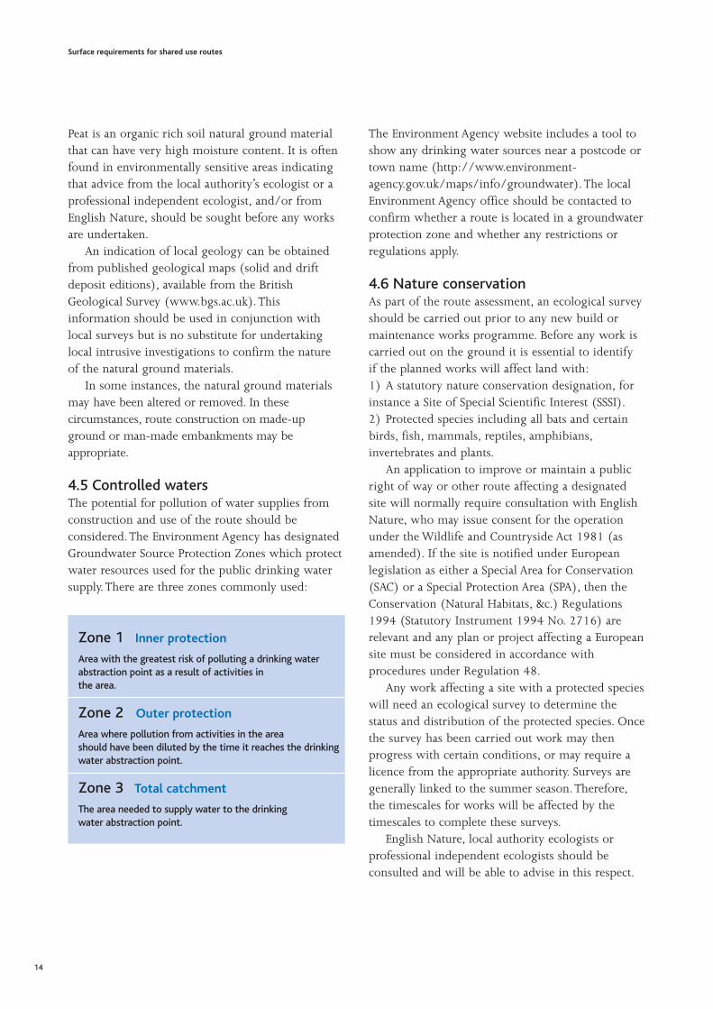
4.5 Controlled watersThe potential for pollution of water supplies fromconstruction and use of the route should beconsidered.The Environment Agency has designatedGroundwater Source Protection Zones which protectwater resources used for the public drinking watersupply.There are three zones commonly used:
The Environment Agency website includes a tool toshow any drinking water sources near a postcode ortown name (http://www.environment-agency.gov.uk/maps/info/groundwater).The localEnvironment Agency office should be contacted toconfirm whether a route is located in a groundwaterprotection zone and whether any restrictions orregulations apply.
4.6 Nature conservationAs part of the route assessment, an ecological surveyshould be carried out prior to any new build ormaintenance works programme. Before any work iscarried out on the ground it is essential to identify if the planned works will affect land with:1) A statutory nature conservation designation, forinstance a Site of Special Scientific Interest (SSSI).2) Protected species including all bats and certainbirds, fish, mammals, reptiles, amphibians,invertebrates and plants.
An application to improve or maintain a publicright of way or other route affecting a designatedsite will normally require consultation with EnglishNature, who may issue consent for the operationunder the Wildlife and Countryside Act 1981 (asamended). If the site is notified under Europeanlegislation as either a Special Area for Conservation(SAC) or a Special Protection Area (SPA), then theConservation (Natural Habitats, &c.) Regulations1994 (Statutory Instrument 1994 No. 2716) arerelevant and any plan or project affecting a Europeansite must be considered in accordance withprocedures under Regulation 48.
Any work affecting a site with a protected specieswill need an ecological survey to determine thestatus and distribution of the protected species. Oncethe survey has been carried out work may thenprogress with certain conditions, or may require alicence from the appropriate authority. Surveys aregenerally linked to the summer season.Therefore,the timescales for works will be affected by thetimescales to complete these surveys.
English Nature, local authority ecologists orprofessional independent ecologists should beconsulted and will be able to advise in this respect.
Surface requirements for shared use routes
14
Zone 1 Inner protection
Area with the greatest risk of polluting a drinking waterabstraction point as a result of activities in the area.
Zone 2 Outer protection
Area where pollution from activities in the area should have been diluted by the time it reaches the drinkingwater abstraction point.
Zone 3 Total catchment
The area needed to supply water to the drinking water abstraction point.
There are some good practice working principleswhich will help to mitigate the effects of surfacingworks on the environment:
• Time works to avoid any period when wildlifemay be vulnerable to disturbance or damage.
• Avoid working in very wet conditions because ofpotential long-term damage to vegetation or soils.
• Avoid ground compaction by heavy machineryand/or storage of materials (which can causelong-term damage to tree roots and damage tosoil structures).
• Use local materials to match local conditions.
• Consider the effects of drainage on adjacenthabitats.
• Consider whether the route and its surfacing fitinto the wider landscape.
• Consider whether the design of a path can providepositive opportunities for people to have beneficialcontact with nature, or to steer people away fromvery sensitive nature conservation areas.
Route surfacing work may affect nature conservationinterests in a number of ways, dependent, in manyinstances, upon the local wildlife found on, adjacentto or near the route. For example, surfacing routesmay affect burrowing wasps which require baresand habitats, and reptiles that use bare ground forbasking and breeding. Route maintenance such asthe clearance of vegetation or cutting of trees andscrub may also significantly impact upon birds anddormice and the provision of infrastructure such asadditional lighting may be a particular issue for bats.
Shared use routes may act as potential routes forcreatures such as small mammals, foxes, reptiles andbadgers to safely cross waterways and roads.
4.7 ArchaeologyConstruction or maintenance of shared use routesmust not cause damage or adverse disturbance toancient monuments or sites of archaeologicalinterest. Sites which are designated ancientmonuments are maintained on the ‘Schedule ofAncient Monuments’, kept by the local authorityarchaeological unit, and protected by the AncientMonuments and Archaeological Areas Act 1979.There are over 200 classes of ancient monument,ranging from prehistoric standing stones and burialmounds through to collieries. A ‘scheduledmonument consent’ is required before work can beundertaken, which is administered by theDepartment for Culture, Media and Sport andEnglish Heritage.
Historic routes of archaeological value, such asbridleways surfaced with pitched stone during theindustrial revolution, should also be protected, evenif they are not scheduled ancient monuments. If indoubt about the archaeological status of a route orits immediate vicinity, contact English Heritage orthe local authority archaeological unit, who will beable to advise in this respect. Local heritage issuesshould also be considered, particularly in materialselection. Materials should match the historicenvironment in both rural and urban areas, andcomplement local distinctiveness.
Surface requirements for shared use routes
15
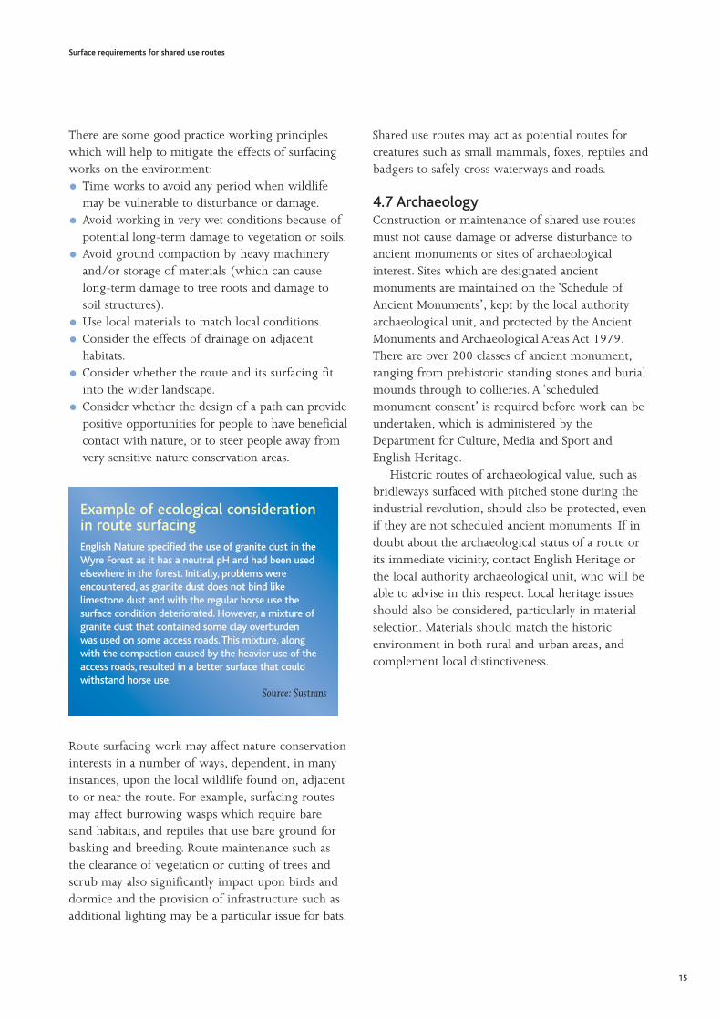
Example of ecological considerationin route surfacingEnglish Nature specified the use of granite dust in theWyre Forest as it has a neutral pH and had been usedelsewhere in the forest. Initially, problems wereencountered, as granite dust does not bind likelimestone dust and with the regular horse use thesurface condition deteriorated. However, a mixture ofgranite dust that contained some clay overburden was used on some access roads. This mixture, alongwith the compaction caused by the heavier use of theaccess roads, resulted in a better surface that couldwithstand horse use.
Source: Sustrans

Example of canal towpath regeneration using materials to suit the local characterA 7 km length of canal towpath in Nottingham is now being used by increasing numbers of cyclists and pedestriansfollowing major reconstruction works. The towpath was underused because of its poor surface condition and encroachingvegetation. The improvement to the route has provided a link from the east and the west of the city to the centre, wherethere are a number of major employers as well as the bus and rail stations, and the tram terminus.
The unbound surface of the towpath had been worn away, resulting in potholes and water ponding. The 2 metre width of theroute had been reduced to 0.5 metres in some places, because of encroaching vegetation from the towpath edgings andacross the canal coping stones. Many of the 20 access points along the route were stepped, restricting access by bicycles,wheelchair users and parents with pushchairs.
Because of the anticipated high usage, the central half of the route was surfaced using block paving, selected as it replicatesthe look of traditional stone setts. The sub-urban areas, the route was laid with an asphalt base and a crushed stone chipsurfacing. The towpath was widened to 3 metres, and access for wheel chairs, cyclists and pushchairs was provided, wherefeasible.
The £1 million improvement works were financed by a partnership between the Greater Nottingham Partnership,Nottingham City Council, British Waterways, the Inland Waterways Association and Wren Recycling, with the phasedprogramme of works completed between 2002 and 2005.
Source: Nottingham City Council
Before and after photographs of the city centre and sub-urban surfacingsPhotographs courtesy of Nottingham City Council (www.nottinghamcity.gov.uk)
Surface requirements for shared use routes
16

5.1 SummaryThe surfacing of shared use routes should beconsidered within the network design process. Thissection does not provide detail on network design.However, information regarding network design iscontained in the ‘Greenways Handbook’[Countryside Agency, 2000], Sustrans’ ‘InformationSheet on Shared Use Routes’ [Sustrans, 2000] andthe Department for Transport’s ‘Policy, Planning andDesign for Walking and Cycling’ (Draft forconsultation) [DfT, 2004a] and ‘Adjacent and SharedUse Facilities for Pedestrians and Cyclists’ (Draft forconsultation) [DfT, 2004b].
In addition to considering the type of surfacingat an early stage of the network design process, earlyconsultation should be conducted to gather users’views, particularly when new routes or significantchanges to an existing surface are proposed.Adequate maintenance is known to be important toavoid conflicts between users of shared use routes.Surfacing choices should also be made to avoidcreating conflicts, although these are known to beinfrequent on shared use routes.
5.2 Planning A creation agreement or order made under theprovisions of the Highways Act 1980 will berequired to create a new route, or to upgrade anexisting route; for example, to upgrade a footpath toa bridleway. An order under the Cycle Tracks Act1984 will be needed to convert a footpath into acycle track. Providing a sealed surface to a previouslyunsealed route may require planning permission. Insome instances, other warrants or consents may alsobe required; for example, consent from EnglishNature or British Waterways.To confirm thatplanning permission is not required contact the localauthority planning department.
Surfacing for shared use routes should beconsidered as part of planning and consultationwithin the route design process. The followingactions should be taken when surfacing constructionor maintenance is being planned:
• Produce specifications and drawings for theroutes, including details of access points, highwaycrossings and so on.
• Specify durable materials that are appropriate tothe local surroundings and the anticipated levelsand types of use.
• Check that the route, and its surfacing, does notspoil an attractive view or habitat, and minimiseecological and archaeological impact.
Where planning consent for a route is required,information on drainage patterns will need to theincluded in the submission. It is important that thecreation or surfacing of shared use routes does notaffect drainage patterns important for the localecology.This should be considered during anecological survey.
5.3 ConsultationWhen new routes are being created, or wheresignificant changes are being made to an existingroute surface, consultation is essential to understandthe needs of users, landowners and localcommunities, and to ensure that an appropriatesurface is chosen.Various consultation processesexist already within local authorities that provide auseful link between users and the authorities. Themost obvious of these links is through the LocalAccess Forum, who are able to advise on schemesand also provide a link to the wider community.
Parish and District Councils can be contacted togather local opinion. Authorities can benefit frominterdepartmental working to share knowledge ofusers’ needs and strategic plans; for example,between Cycling Officers and Rights of Way Officers.In addition, many local authorities issue newslettersto residents which can be used to publicise plansand gather feedback.
Surface requirements for shared use routes
17
5 Planning, consultation and avoiding conflict

5.4 Avoiding conflictResearch for the Countryside Agency found thatconflict on shared use routes is infrequent, and thatusers change their speed and pattern (moving to oneside) to accommodate other users [CountrysideAgency, 2001]. However, by studying routes whereconflict was known to occur, further researchidentified that structural issues such as route widthand maintenance were important factors[Countryside Agency, 2003b].This indicates thatmaintenance of surfacing and removal of vegetationto the full width, of the route, where feasible, willbe helpful as measures to avoid conflict.
Care must be taken when considering the type ofany surface provided, to ensure potential conflict isminimised.The appropriate selection of surfacesshould be used to avoid conflicts. For example,surfaces which can encourage fast cycling speedsshould be avoided for routes with steep gradientsand poor forward and peripheral vision, or thesurfacing should include chicanes or other featuresto reduce cycling speeds.
The research made the following recommendationsto minimise conflict on shared use routes[Countryside Agency, 2003b]:
• Developing a Code of Conduct that details therights and responsibilities of all user groups inorder to reduce ambiguities surrounding issuessuch as right of way, passing etiquette, themeaning of bells, control of dogs, and the speedsthat should be adopted for safety and courtesy. Forexample, the British Waterways Code of Conductfor All Users and the Code of Conduct forCyclists, available athttp://www.britishwaterways.co.uk
• Policing of shared use routes to ensure that usersknow they are actively managed.
• Placing information panels at the access points toshared use routes detailing the Code of Conductas well as the contact person in the responsibleagency for maintaining the route and to whomcomments, complaints and reports of conflictshould be directed.
Surface requirements for shared use routes
18
LOOK AFTER YOUR WATERWAYS• Avoid cycling where your tyres would damage thepath
or verges (eg when they are wet or soft).
CONSIDER OTHERS• Give way to others on the towpath and warn them of
your approach. Pedestrians have priority.A polite ‘hello’ and ‘thank you’ mean a lot.
• Watch out for anglers’ tackle and give them time tomove it before you try to pass.
• Dismount under low, narrow or blind bridges.
• Never race one another or perform speed trials.
• We recommend you obtain third party liabilityinsurance and equip your bike with a bell or hooter.
TAKE CARE• Access paths can be steep and slippery. Join and leave
the towpath with care.
• You must get off and push your cycle beneath low orblind bridges, and where the path is very narrow.
• We strongly advise against cycling the towpath afterdark, but if you have to, use front and rear lights.
• Thorny hedge trimmings can cause a puncture.We recommend plastic-reinforced tyres.
Only cycle on stretches where it is permitted.
Check with the local waterway office or
www.britishwaterways.co.uk.
The British Waterways Code of ConductCyclists You need a permit and information telling you which stretches are open to cyclists.
6.1 SummaryAvailable budget is usually the greatest constraint onthe selection of surfacings for shared use routes. It ispreferable to apply for additional funding to achievea surface that minimises whole life costs, suits theenvironment and character of the route, and meetsusers’ needs, rather than using less expensivematerials with a shorter life-span, which do not suitthe route or its users. If the available budget isinsufficient, smaller sections of work can beundertaken until the remaining budget is available,as along as a piecemeal approach can be avoided.
Costing of works should examine the capital andmaintenance costs of the route surfacing. Withoutsufficient budget for long-term maintenance, theroute will not provide the facility planned by thelocal authority or promoter and required by users.
6.2 BudgetsThe first choice surfacing should be preferred over alower cost, less suitable option. If the budget isrestricted, consider a phased programme of work toprovide the fit for purpose surface. Phasing couldprioritise route sections which require urgent work,or tackle a reduced length of route, and completethe surfacing when more funding becomes available.It is important to understand that two forms ofbudget are required for shared use routes.These are:
• Construction budgets - the costs associated withthe physical construction of the route.
• Maintenance budgets - the realistic costs to keepthe route fit for purpose.
Only by considering both forms of budget whenselecting a surfacing can the ‘whole life costs’ of theroute be minimised. It should also be rememberedthat whichever surfacing is selected, othermaintenance costs associated with the route will stillbe incurred, such as clearing vegetation, clearingdrains and maintaining signs. Anecdotal evidencesuggests that maintenance of the surfacing is only30% of overall route maintenance costs.
When the costs of maintenance are consideredduring the planning of surfacing works, therequirements for effective maintenance, and itscosts, are understood and it is more likely to occur.Opting for lower cost maintenance may initiallyoffer a cost benefit, but ultimately may incur greatercosts for remedial or repair works in the long-term.
6.3 FundingSince highway authorities have a statutory duty tomaintain the surface of most public rights of way,these activities will not be eligible for additionalfunding. Additional funding for shared use routeconstruction may be available from authority budgetsaimed at promoting non-vehicular access and moreenvironmentally sustainable transport routes. Creativefunding packages, sometimes through a range ofpartners, can provide for long-term maintenance by,for example, providing initial capital funding for a 3year period, during which a group of maintenancevolunteers will have been developed.
Surface requirements for shared use routes
19
6 Budgets and Cost Considerations
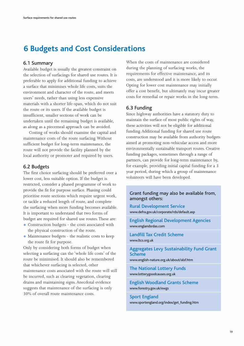
Grant funding may also be available from,amongst others:
Rural Development Servicewww.defra.gov.uk/corporate/rds/default.asp
English Regional Development Agencieswww.englandsrdas.com
Landfill Tax Credit Schemewww.ltcs.org.uk
Aggregates Levy Sustainability Fund GrantSchemewww.english-nature.org.uk/about/alsf.htm
The National Lottery Fundswww.lotterygoodcauses.org.uk
English Woodland Grants Schemewww.forestry.gov.uk/ewgs
Sport Englandwww.sportengland.org/index/get_funding.htm

6.4 Costs of construction andmaintenanceConstruction and maintenance costs vary widely,depending on the type of route construction and itslocation and access. For example, indicative costs forsoil inversion (soil reversal) route construction inthe Lake District can be in the order of £6 perlinear metre.
In remote access areas the use of specialist plantand equipment will have a significant effect oncosts, but allow works to be carried out whereotherwise this would not have been possible.
The costs of flying materials to site by helicopter isabout £30 per tonne, but this is often quicker, lessexpensive, causes less damage and has fewer healthand safety implications than alternative transportmethods.
For more conventional shared use routeconstruction (such as unbound or sealed surfaceconstruction), indicative costs range from £20 to£50 per linear metre. Further details for varioussurface construction and maintenance costs areprovided in Appendix A.
Surface requirements for shared use routes
20
Indicative costs for construction and maintenance of various 2.5 m wide surfaces on the Camel Trail in Cornwall are:
Surface Construction cost Cost when maintenance required Maintenance scheme
Unbound – dust blinded £25/linear m £5 to £15/ linear m From cleaning to regrading tosub-base material (45mm down) planing and re-blinding.
Sealed/dressed surface – £31/linear m £20/linear m For making up sealed surfacesBitumen spay & chip on with planings and re-sprayingsub-base material with bitumen and surface(45mm down) dressing.
Sealed bituminous macadam £55/linear mon sub-base material (45mm down) Source: Cornwall County Council
Phot
ogra
ph c
ourt
esy
of t
he N
atio
nal T
rust
(w
ww
.nat
iona
ltrus
t.org
.uk)
Flying materials to maintain and repair remote routes
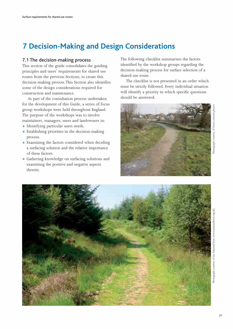
7.1 The decision-making processThis section of the guide consolidates the guidingprinciples and users’ requirements for shared useroutes from the previous Sections, to create thisdecision-making process. This Section also identifiessome of the design considerations required forconstruction and maintenance.
As part of the consultation process undertakenfor the development of this Guide, a series of focusgroup workshops were held throughout England.The purpose of the workshops was to involvemaintainers, managers, users and landowners in:
• Identifying particular users needs.
• Establishing priorities in the decision-makingprocess.
• Examining the factors considered when decidinga surfacing solution and the relative importanceof these factors.
• Gathering knowledge on surfacing solutions andexamining the positive and negative aspectstherein.
The following checklist summarises the factorsidentified by the workshop groups regarding thedecision-making process for surface selection of ashared use route.
The checklist is not presented in an order whichmust be strictly followed. Every individual situationwill identify a priority in which specific questionsshould be answered.
Surface requirements for shared use routes
21
Phot
ogra
ph c
ourt
esy
of t
he N
atio
nal T
rust
(w
ww
.nat
iona
ltrus
t.org
.uk)
Phot
ogra
ph c
ourt
esy
of G
reen
cre
scen
t ph
otos
7 Decision-Making and Design Considerations

Establish the scenario for the shared use route
What is the legal status of the shared use route (select those that apply)?Footpath Bridleway Cycle Track Restricted Byway Permissive Private Rights
What is the setting for the shared use route?Urban Urban – Rural Fringe Rural
What is the general intended purpose of the shared use route (select those that apply)?Utility (including commuting) Recreation (not to a specific destination) Leisure (to a specific destination)
Establish the local environment and conditions for theshared use route
What is the current condition of the existing/proposed shared use route?
• Is there a route priority?
• What is the available width, alignment, gradient, topography, natural ground material, and existing surface type (if any)?
• Carry out an assessment of the route – e.g. climate, gradient, ground and surface conditions.
What are the user requirements for the shared use route?
• What are the daily, weekly and seasonal timing of user flows, and levels and type of use, both current and potential?
• Are surfacing requirements different for certain user groups (and can a compromise be achieved?)
• Ensure any potential constraints to users are minimised (i.e. all ability access).
What are the potential environmental, ecological or archaeological impacts of theshared use route surface?
• Ensure ecological, habitat and conservation considerations have been addressed. Consult with relevant statutory/non-statutory
nature conservation bodies and where necessary seek professional ecological advice for appropriate survey and assessment
support.
• Check if surfacing or surfacing works will impact on ancient monuments or sites of archaeological or historical interest, or locally
important heritage features. Carry out a survey if necessary.
What are the drainage characteristics for the shared use route?
• Is the existing drainage effective?
• Implement pollution prevention during and after construction.
• Minimise immediate and long-term impact on groundwater table.
Establish planning status of the shared use route andthe need for consultation
Is consultation required?Yes No
Surface requirements for shared use routes
22

Has consultation with public/users/landowners on surfacing option(s) been undertaken?Yes No
What is the planning status? Is planning application/permission required?Yes No
Are any other consents required to do the work?Yes No
Establish the options for managing the surface of theshared use route
What option(s) are most appropriate to the route?Do nothing or do little Restrict access Maintain Upgrade
Once you have made the decision which option(s) you would like to adopt for a particular route - for example, maintenance -
you should consider the following issues.
What are the budget and cost considerations for the shared use route surface?
• What is the available budget?
• Balance capital costs versus maintenance cost/maintenance schedules.
• Consider all maintenance requirements in budget forecasting.
What are the option(s) for surfacing materials and construction/maintenance of theshared use route?
• Consider the durability of the surfacing over the whole life of the surface.
• Remember that the solution should not jeopardise the usage, and alternative routes should be provided when access is restricted.
• Consider the availability of suitable material and the utilisation of locally available materials
• The aesthetics of the surfacing should suit the surrounding area; consider landscaping to minimise visible impact if necessary.
• Use full depth construction.
• Are there seasonal constraints on construction?
• Plan timing of the surfacing works against popular usage times
• Avoid any sensitive period when birds or animals may be vulnerable to disturbance.
What controls may be used to ensure appropriate use of shared use routes?
• What are the implications of the surfacing solution on future use?
• Will the surfacing encourage conflict or inappropriate use?
• Is there a Code of Practice for users/landowners?
• Can other influencing factors be managed; for example, surrounding vegetation, access controls, signage and lighting; dog fouling;
potential for fly-tipping and other illegal usage.
• Remember that path furniture should be suitable and easy to use, and has road safety implications at intersections with the
road network.
Surface requirements for shared use routes
23

7.2 Design considerationsThe following aspects of route design should beaddressed as part of the decision-making process:
• Route alignment.
• Balancing earthworks requirements(import/export of materials, using local sources).
• Surfacing type and construction (full depth orpartial).
• Segregation, barriers and edging.Waymarking is not considered in this Guide;information can be found in the County SurveyorsSociety Countryside Working Group’s ‘Report on theSurfacing of Bridleways’ [CSS, 2005]. Drainageaspects and surfacing type and construction arediscussed in detail in Section 9.
7.2.1 Route alignmentThe alignment of shared use routes should bedesigned to suit or enhance the local landscape andenvironment and be sensitive to the naturalsurroundings.The realignment of existing routesshould only be considered when there is a beneficialreason for doing so, such as producing an alignmentthat blends better with the landscape or protectsarchaeological or ecological features.
When planning route alignment, if possible,design the route to make it interesting for users, andto minimise potential conflicts. Routes should ideallyfollow natural contours or existing desire lines, toavoid users creating new short cuts. Long linearlengths with steep gradients, should be avoided,especially in high rainfall areas prone to erosion.
7.2.2 Segregation Shared use routes, with segregated sections fordifferent users, do exist. Segregation can range froma physical kerb or verge between different surfacings,to a tactile or painted line on the same surface.Whether segregation is needed, and what form ittakes, depends on the expected level and type of useand should be considered as part of route design.
Guidance on types and minimum widths forsegregation are provided in the ‘Greenways Handbook’[Countryside Agency, 2000], Sustrans’ ‘National CycleNetwork - Guidelines and Practical Details’ [Sustrans,1997] and the Department for Transport’s ‘Adjacentand Shared Use Facilities for Pedestrians and Cyclists’(Draft for consultation) [DfT, 2004b].
Surface requirements for shared use routes
24
Phot
ogra
ph c
ourt
esy
of S
ustr
ans
(ww
w.s
ustr
ans.
org.
uk)
A segregated route for cyclists and pedestrians
Phot
ogra
ph c
ourt
esy
of S
cott
Wils
on P
avem
ent
Engi
neer
ing
(ww
w.s
wpe
.com
)
Surface erosion of a route on a gradient

The Greenways Handbook recommends thatsegregated paths be considered when:
• There are significant user flows.
• There are concerns for blind/visually impaired people.
The Department for Transport’s draft publication[DfT, 2004b] recommends “a presumption in favour of segregation” of pedestrian and cycle traffic.Reasons for and against segregation are given as:Reasons to segregate a route
• If high flows of pedestrians or cyclists are expected.
• If disabled people or other vulnerable users arelikely to use the facility frequently.
• If there is sufficient width available.Reasons to not segregate a route
• If flows of pedestrians or cyclists are expected tobe low.
• If flows of pedestrians in particular are expectedto be very low.
• If disabled people or other vulnerable users areunlikely to use the facility.
• If there is limited width available.For unsegregated cycling/walking routes, theGreenways Handbook [Countryside Agency, 2000],the Sustrans Guidelines [Sustrans, 1997], and theDepartment for Transport (DfT) draft publication[DfT, 2004b] recommend:
• A minimum width of 3 metres.
• An absolute minimum of 2 metres but only iftraffic flows are less than 200 users per hour andthere is a clear verge on each side of the route.
However, the Sustrans Guidelines [Sustrans, 1997]recognise that high cycling and pedestrian trafficflows can be accommodated on restricted widthpaths when the routes are delineated with a whiteline. Reference should be made to these guidelinesfor routes where smaller widths are available. Wheresegregation is not possible, but traffic flows areexpected to be large, measures to encourage carefuluse must be included in the route design.
Canal towpaths and other routes by waterways canhave a limited verge on either side of the route and areconstrained by the waters edge. For cycling/walking routes on canal towpaths, the SustransGuidelines [Sustrans, 1997] recommend a minimumwidth of 2 metres for the route, with a clearance of1.2 metres to the canalside; for example, toaccommodate anglers or boat moorings. On towpaths,the route design needs to consider the construction ofbank protection, such as tiebacks, piling and bio-engineering.Tiebacks must not jut into the towpath.Canal towpath work will normally involve BritishWaterways, who should always be consulted at anearly stage (details provided in Appendix B).
For segregated routes, the DfT draft publication [DfT2004b] recommends a width for urban footways onlocal roads of 2 metres, which allows users withpushchairs or in wheelchairs to pass comfortably.The minimum acceptable width for a footway orfootpath is 1.5 metres, which allows a pedestrian topass a wheelchair user. An absolute minimum widthof 1 metre is permissible if users are unlikely toneed to pass or overtake one another.This absoluteminimum should not extend for more than 6 metresalong the route. Optimum widths for segregatedpedestrian and cycling routes [Sustrans, 1997].
Surface requirements for shared use routes
25
The desirable widths of shared cycle tracks/footpaths [Sustrans, 1997]
The desirable widths of shared canal towpaths [Sustrans, 1997]
boundary walls, frontages etc.)
0.5m 3.0m preferable
(2.0m absolute min)
0.5m Desirable min clearance
to objects. (0.75m against
Cycle Track
3.0m
Pedestrian
2.0m
5.0m

The minimum recommended width [DfT, 2004b]for a segregated cycle track on local roads is 3metres.The minimum acceptable width is 2 metres.However, an absolute minimum width of 1.5 metreson a cycle track will allow users to pass one anotherwith difficulty.This absolute minimum on a cycletrack is not as onerous as the absolute minimum fora footpath or footway.The Sustrans Guidelines[Sustrans, 1997] suggest similar optimum widthsfor segregated cycling and walking routes.
For routes which carry horse-riders, theGreenways Handbook [Countryside Agency, 2000]recommends segregation from pedestrians andcyclists, and the provision of separate surfaces. Forhorse-riding routes, which can be segregated orshared use, the Handbook recommends:
• An optimum width of 4 metres, to take twohorses abreast and allow passing.
• A desirable minimum width of 2.9 metres, whichallows a horse to turn.
• An absolute minimum width of 2 metres.Thisabsolute minimum should only be considered ifthere is an open verge, where traffic flows are lowand where passing and turning are not necessary.
The British Horse Society suggests an ideal width of5 metres for newly created or diverted routes, butconfirms 4 metres as an optimum and recognisesthat many perfectly acceptable bridleways are 3metres or less. It should be noted that, if the widthof a route is proven, e.g. by inclusion in thestatement accompanying the Definative Map, thenthat is the defined width (i.e. the minimum and themaximum). If the width of a shared use routecannot be proven, the minimum widths suggestedmay apply, not withstanding that actual space whichmay be available.
Tactile surfaces and raised dividing lines helpblind and partially sighted people to positionthemselves and stay on the correct side of asegregated route [DfT, 1990]. Where raised dividinglines are used, care should be taken not toinadvertently create a trip hazard.The British HorseSociety has some reservations about segregation,which could constitute a hazard on shared useroutes.
7.2.3 BarriersThe use of barriers and physical segregation can bean obtrusive and unwelcome aspect of shared useroutes. However, the occasional use of barriers maybe required; for example, fencing stock control orbalustrades on narrow under-bridge sections ofcanal towpaths. Barriers should not prevent access bymobility impaired users, whether on foot, in awheelchair, on a pedal cycle, on horseback ordriving a horse-drawn carriage.
There are circumstances - for example, whereshared use routes intersect with busy roads - whereaccess controls can increase the safety of legitimateusers, making them aware of the road hazard andcausing them to slow down. However, in general,the use of barriers as access controls should formpart of the design considerations and be minimisedwherever possible.
Barriers are often used as access controls to preventillegal use but this is often ineffective and causesinconvenience to the wide range of legitimate users.Regular use of shared routes by legitimate users canassist in minimising illegal use, thus eliminating theneed for barriers. Route design can also minimiseillegal use; for example, having convoluted andunattractive route entrances may minimise illegalmotorcycling.
Surface requirements for shared use routes
26
Phot
ogra
ph c
ourt
esy
of C
TC (
ww
w.c
tc.o
rg.u
k)
Example of route furniture designed to slow cyclists as they approach aroad crossing
7.2.4 EdgingsThe use of path edgings also needs carefulconsideration during route design and selection ofsurfaces for shared use routes.The requirement foredging depends on the local circumstances andshould be assessed on an individual route surfacingdesign basis, not as a default component of routeconstruction. Further details of edging can be foundin [Sustrans 1999]. Edges can be essential to preventlateral spread of surface materials, particularlyunbound materials such a fibre reinforced sand orwoodchips.
The unnecessary use of edging materialsincreases the costs of construction and may detractfrom the route aesthetics, giving the route an urbanfeel. Local authorities may specify the use of precastconcrete kerbs as a matter of course, as a part oftheir local highway maintenance standards.Treatedtimber edgings can be used where the routeaesthetics call for an alternative to precast concretekerbs.The use of grass verges softens the visualintrusion of a route.Verges should slope away fromthe edge of a route surface to shed surface water.
If the route surface settles, edgings may becomeproud of the surface. Proud edgings keep water onthe route and lead to ponding, erosion and scour,instead of promoting drainage and run off. Edgingsproud of the surface may also become a trip hazardand the unnecessary use of edging should beavoided when the verges of a route are intended toprovide the second surface on a dual surface route.
Surface requirements for shared use routes
27
Phot
ogra
ph c
ourt
esy
of S
cott
Wils
on P
avem
ent
Engi
neer
ing
(ww
w.s
wpe
.co.
uk)
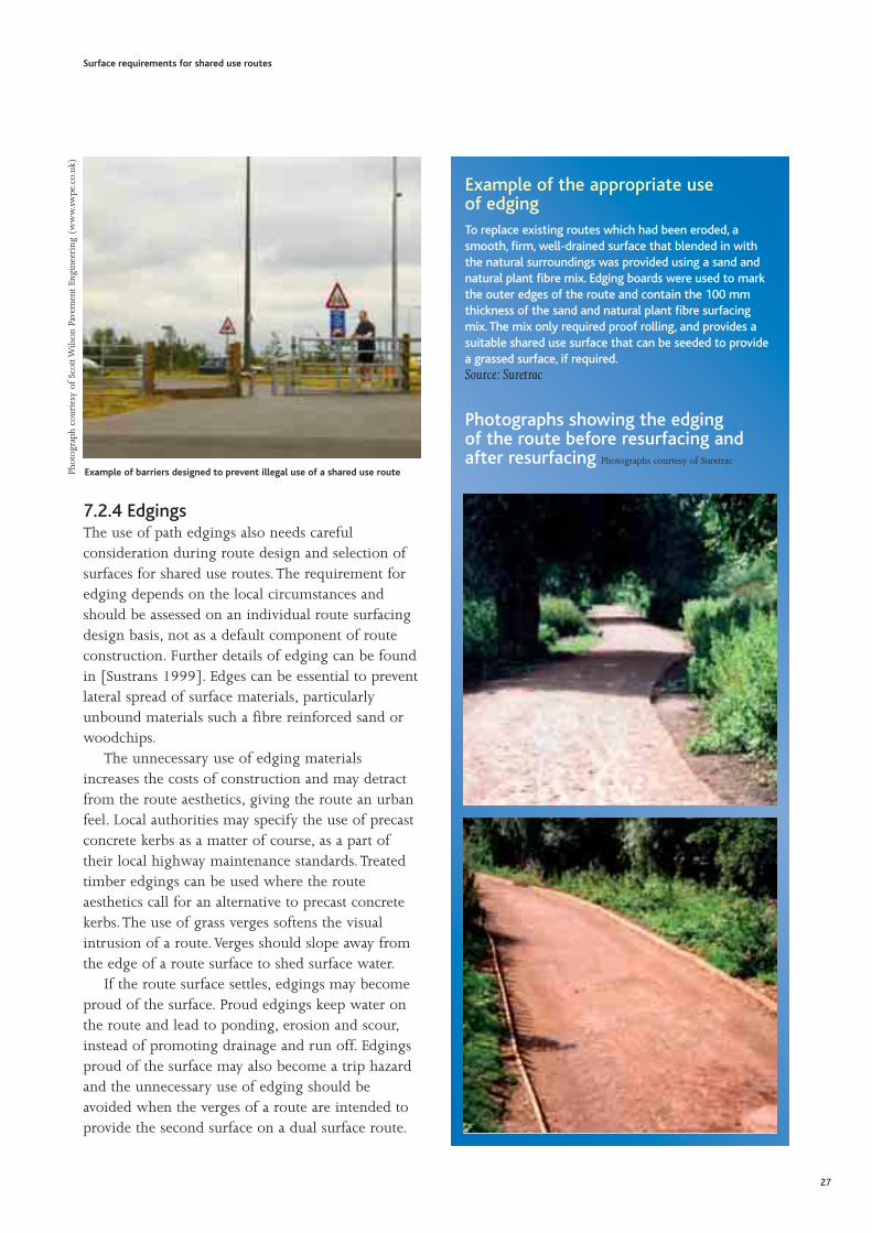
Example of barriers designed to prevent illegal use of a shared use route
Example of the appropriate use of edgingTo replace existing routes which had been eroded, asmooth, firm, well-drained surface that blended in withthe natural surroundings was provided using a sand andnatural plant fibre mix. Edging boards were used to markthe outer edges of the route and contain the 100 mmthickness of the sand and natural plant fibre surfacingmix. The mix only required proof rolling, and provides asuitable shared use surface that can be seeded to providea grassed surface, if required.Source: Suretrac
Photographs showing the edging of the route before resurfacing andafter resurfacing Photographs courtesy of Suretrac

7.2.5 Health and SafetyAll construction and maintenance activities onshared use routes should comply with the Healthand Safety at Work Act 1974 and the Management ofHealth and Safety at Work Regulations 1999(Statutory Instrument 1999 No. 3242). Everyconstruction activity should be accompanied by arisk assessment and method statement. Generic riskassessments and method statements can be preparedfor routine activities (such as vegetation clearance)but reviewed to include site specific details (such asrisks associated with overhead cables). Staff shouldhave received training appropriate for the work theyundertake.The Construction Industry Training Board(CITB) provides safety training and certification forengineers, construction staff, surveyors, manager andplant/machine operators (http://www.citb.org.uk).
The Construction (Design and Management)Regulations 1994 (Statutory Instrument 1994 No.3140) apply to all construction projects whichinvolve demolition or dismantling activities, or lastlonger than 30 days, or involve more than 4 peopleon site at any time, including supervision orinspection.The Regulations aim to ensure that healthand safety is considered at all stages of theconstruction project process, from initiation throughdesign to construction and subsequent maintenance.Major resurfacing projects and route constructionprojects are likely to be covered by theseRegulations.
The Health and Safety Executive provide guidanceon these and other Regulations important toconstruction and maintenance activities (visit http://www.hse.gov.uk/construction).Other relevant Regulations include
• Manual Handling Operations Regulations 1992(Statutory Instrument 1992 No. 2793)
• The Personal Protective Equipment Regulations2002 (Statutory Instrument 2002 No. 1144)
• The Construction (Health, Safety and Welfare)Regulations 1996 (Statutory Instrument 1996 No. 1592)
• The Provision and Use of Work EquipmentRegulations 1998 (Statutory Instrument 1998 No.2306)
7.2.6 Voluntary workMany organisations rely on volunteer input toundertake route construction and maintenance.Details of health and safety issues for volunteergroups can be found in ‘Footpaths - A PracticalHandbook’ [Agate, 1996] and on the WaterwayRecovery Group website (www.wrg.org.uk).
The site specific risk assessment associated shouldbe assessed by a suitably qualified person, whichcould be a member of the voluntary group. Manyvoluntary groups, particularly those which carryinsurance for their volunteers, have approved ‘projectleaders’ who will take responsibility for overseeingthe health and safety aspects of the work.
This project leader is responsible for briefingother volunteers and ensuring that the correct toolsand protective equipment are available.The projectleader will also have a supervisory role during thework, ensuring that protective equipment is beingused and the work is being undertaken in a safemanner. If more than one work ‘gang’ is anticipatedon any site, assistant project leaders will be needed.
In addition, project leaders should obtain andcarry with them any permissions or consentsrequired to undertake the work, such as consentfrom English Nature or British Waterways. It isprudent for project leaders to publicise the work sothat users and adjoining landowners are aware whatis being done, and when.
Volunteers contribute to site safety by behavingin an appropriate manner, and should adhere to thehealth and safety policy of the voluntary group theyare working for.Volunteers must have realisticexpectations of their own abilities, and notoverextend themselves.They should make the projectleader aware of any medical conditions, previousinjuries or other issues which will affect the workthey can undertake, or their ability to respond incase of an emergency, such as exiting an area if a firestarts or running to get help when there is anemergency.
Surface requirements for shared use routes
28

8.1 SummaryThe purpose of maintenance is to keep the route ina condition suitable for its intended use throughoutits length, or to prevent impact on the surroundinglandscape. Effective maintenance can also preventmajor deterioration occurring and minimise theextent over which repairs are needed.The need formaintenance plant to access shared use routes shouldbe included within the decision making processwhen considering the construction of the surface.The decision-making process presents a series ofoptions for the management of shared use routesurfaces.These options are as follows:
• Do nothing or do little – (without compromisingthe safety of users)for example, minimumintervention may be appropriate for a route inpoor condition if alternative routes in goodcondition are being promoted to take the traffic.
• Restrict access – for example, prevent access toprotect a route through an ecologically sensitiveenvironment.
• Maintain, which is further subdivided asReactive maintenance, which addresses problemsas they manifest, such as pothole repair.Planned maintenance, carrying out routine taskswhich prevent problems occurring, such as clearingdrains to prevent water ponding on the route.
• Upgrade – Placing a surfacing on a route withpoor natural ground material that cannot supportthe traffic, for example. Information on upgradingthe route surfaces is given in Section 10.
This section of the Guide covers aspects of minimalintervention, restriction and maintenance of surfacesfor shared use routes.The best practice guide, ‘Repairing Upland PathErosion’ recommends that the following principlesare accounted for when undertaking maintenance onroutes in open country [Davies et al, 1996]:
• Repairs are only undertaken when required toprevent or ameliorate visual intrusion andenvironmental damage.
• Works should be of a high standard of design andimplementation and use indigenous materials that aresympathetic to the immediate surroundings.The visualimpact of the work should be minimal; for example,steps and straight line routes should be avoided.
• The existing vegetation should be protected andthe methods of working should minimise thepotential for damage. For example, it is preferableto fly machinery to site rather than to drive itover open ground. In most circumstances, onlylocal plant species are used in restoration.
• As a general rule, the more remote, wild or scenicthe route is, the greater the visual impact of theunsuitable works will be.The surfacing design insuch locations needs to be evaluated carefullybefore any work is undertaken.
• The routes should be constructed to meet theintended use.
• All the alternatives should be examined.The bestpractice guide specifically states, “Before anyrepair work is agreed the question should beasked ‘is there a better solution’?”
It is important to recognise that typically only 30%of maintenance costs for shared use routes relatesolely to the surface.The remaining 70% of costs arerelated to other influences, such as drainage andvegetation management.The importance of effectivedrainage and the use of geosynthetic materials, thatis geotextiles and geogrids, are two areas of overlapbetween maintenance and surface construction.Details of drainage, and the use of geosynthetics,are presented in Section 9.
8.2 Do nothing or do littleIf the local situation warrants, it may be appropriateto do nothing to a route. For example, if:
• The route can sustain current traffic flows withoutintervention, but with monitoring of the surfacecondition if user numbers increase.
• There is only a small budget available and theroute will not deteriorate further because trafficflows are reducing as alternative routes becomemore popular.
• The route is suitable for the majority of users andintervention would jeopardise their use.
• The route is an ecologically valuable habitat thatintervention would damage.
Surface requirements for shared use routes
29
8 Maintenance of shared use routes

• The route suits the character of the area andintervention would be visually harmful.
It should also be remembered that a strategy of doingnothing should not be to the detriment of the route.Minor repairs conducted in a timely manner (reactivemaintenance) can prevent further route deterioration.For example, potholes in a surfaced route will pondwater and users will in preference use the verge,potentially extending the damaged area, particularly if the verge cannot support the traffic.
In some areas where historic roads have been leftunmaintained for a number of years, an excellentsurface for shared use routes can develop.This typeof route has strength and drainage provided by theoriginal road construction, with a thick covering ofgrass resulting from natural processes ofsedimentation and re-vegetation.This can create asurface suitable for use in all weathers. Improvedgrass cover may be better for the horse-rider, walkerand mountain biker, although not necessarilysuitable for the casual cyclist. Re-vegetation ofsurfacings containing recycled asphalt planings willoccur, if the material is not over-compacted.
8.3 Restrict accessAccess restrictions are difficult to enforce andunpopular with users. Advanced notice todisseminate information on closure should always be undertaken, as should notification when therestriction is lifted. Restrictions should not beconsidered unless safe alternative routes are available.These alternatives should also be publicised.
Deterioration of popular shared use routes canoccur, the repair of which may often be bestmanaged by allowing the route to be temporarilyclosed.Temporary diversions around areas thatrequire maintenance or areas which have recentlybeen maintained are also possible; for example,restricting the width of a route to avoid a recentlyseeded area.
Surface requirements for shared use routes
30
Example of a re-vegetated historicroad in the North Pennines Area ofOutstanding Natural BeautyThis photograph shows a moorland bridleway in the NorthPennines, which has almost certainly developed on astone base of a historic track, probably an old road fromformer mining industry in the area. The track is engineeredinto the slope and is buried under soil and the grasssward. The route is typical of historic ‘ledge’ tracks in thenorthern uplands.
Source: British Horse Society, North of England
Photograph courtesy of Sue Rogers
Example of re-vegetation of a recycledasphalt surfacingIt is important to recognise that overused routes may notbe provided with sufficient opportunity to re-vegetate.Particularly in upland areas, worn away vegetation canresult in topsoil being washed out, followed by significantroute erosion, and the path becoming a scar on thelandscape. However, minimal intervention, such asfertilising and reseeding with local species, may besufficient to reinstate the route, or prevent significanterosion occurring on routes at risk of erosion [Davies et al,1996]. Fertilising and seeding should normally take placeat the beginning of the growing season.Photograph courtesy of Scott Wilson Pavement Engineering (www.swpe.co.uk)

Restricting access to shared use routes can be used toprevent route deterioration and ensure user safety (byprohibition).This approach can be used where theinstallation of durable surfacings is inappropriate buttraffic levels are too high for the natural groundmaterials to support. For example, it may beappropriate to restrict access on one route leading to apopular beauty spot, diverting users to alternatives.Natural consolidation and re-vegetation of the closedroute will occur, taking several years withoutintervention; a route does not quickly ‘heal’ itself.Thisapproach of ‘resting routes’ is recommended by thebest practice guide ‘Repairing Upland Path Erosion’ forroutes which are usually wet or steep, and prone toerosion [Davies et al, 1996].The guide also recommendsfertilising and seeding to “boost” recovery.
Restricting access to divert users from areaswhich cannot sustain traffic because of theirecological or archaeological importance is alsopossible. However, if these restrictions need to be inplace permanently, it is desirable to divert the shareduse route, rather than just close it.
Under provisions of the Countryside and Rightsof Way Act 2000 (yet to be commenced) EnglishNature will be allowed to apply for SSSI diversionorders if public use of a right of way is causing, oris likely to cause, significant damage to the flora,fauna, geological or physiographical features of thesite. English Nature will only consider makingapplications for SSSI diversion orders if there issufficient evidence that damage will take place, andif alternative measures, such as access restrictions,have been tried. Such diversions may only take placeto protect the features for which the site is of specialinterest.
Upland areas subject to sheep grazing arevulnerable to the breakdown of vegetative cover, andto significant erosion. For the protection of theroute, fencing may be required to stop grazing onthe location, combined with a programme offertilising and reseeding. Erecting fencing should beconsidered a temporary measure, and will be easierto implement with the consent of the landowner.Further details on fencing in upland areas arecontained in ‘Repairing Upland Path Erosion – A BestPractice Guide’ [Davies et al, 1996].
8.4 Reactive maintenanceReactive maintenance identifies and corrects problemsand potential problems, by means of an inspectionprocess. Reactive maintenance can include removingdog fouling or broken glass from routes when theseissues are highlighted by concerned users.
A planned inspection process will involvesurveying the route surface on a regular basis, thefrequency of surveying dependent on the routelocation, its usage and its surface type. For example,the publication ‘Lowland Path Construction’[Scottish National Heritage, 2001], suggests weeklyinspection of a specific route surfaced with glassreinforced surface dressing, fortnightly inspection ofa unbound ‘blinding’ surface and monthlyinspection of surfacing in a woodland area.Theseinspections are an important part of a plannedmaintenance process, highlighting the maintenancerequired to prevent route deterioration.
Serious problems are often initially reported byusers directly to the relevant authority or through theparish or district council. Immediate or full repairsare not always possible and temporary repairs may beundertaken. Sufficient warning should be given tousers if temporarily unsafe surfaces are present.
‘Quick fixes’, such as redressing a surface layer,may provide effective maintenance in someinstances, but if a repair is required every few years -for example, as a result of regular surface erosion -then more robust surfacings may be appropriate.Further details on the repair of erosion damage inupland areas (which also includes proactivemaintenance, counter-erosion programmes such asre-vegetation) are available from the best practiceguide ‘Repairing Upland Path Erosion’ [Davies et al,1996] and the Lake District National Park Authority’sFootpath Erosion Factsheet [LDNPA, Undated].
Harrowing or regrading the surface to provide acrossfall or a camber will encourage the route toshed water.This technique can be relativelyinexpensive, costing less than £2.50 per linear metre[Scottish National Heritage, 2001]. It also reuses thein situ materials, avoiding the environmental damageof mineral extraction and haulage. However, thesetechniques can have only a short life span, can beaesthetically unattractive and the route may appearuncared for, thereby attracting misuse. Crossfalls arenot preferred by wheelchair or pushchair users.
Surface requirements for shared use routes
31

Infilling potholes can be cost effective (dependingon the size of the hole), particularly if funds arelimited. Infilling is a solution with minimaldisturbance to the overall route. However, thistechnique does not provide a long-term solution aspotholes will return if the cause has not beenresolved.The use of reactive maintenance andinspection is usually used in combination withlonger term planned maintenance schemes. Forexample, a temporary repair infilling a pothole isconducted to ensure a route can remain open, whilea planned longer term solution is being arrangedand implemented.
Further details on crossfall/camber requirementsand pothole repairs are provided in Appendix A1and A2 respectively.
8.5 Planned maintenancePlanned maintenance is carried out to preventproblems before they occur, as part of a regularmaintenance schedule. Planned maintenance mayinclude regular redressing and re-compaction ofsurfacing materials or removing litter or leaves froma route surface. Indicative costs are between £1.50per square metre for redressing [Davis Langdon andEverest, 2004] and £0.10 per square metre forremoving debris [Scottish National Heritage, 2001].Surfacing maintenance is often best carried out inearly spring, after any winter frost damage hasoccurred.
8.5.1 Vegetation managementHighway authorities have a statutory duty to controlvegetation growing from the surface of shared useroutes, and landowners have a duty to removeoverhanging vegetation. Clearing vegetation helpskeep the shared use route free of obstructions andcan help the route surface dry out. Removingvegetation from the route verges and surroundinghedgerows allows the route to be used over the fullwidth, rather than concentrating it in the centre ofthe route.This clearance often forms one of the mosteffective means of maintaining surfaces on shareduse routes and should be incorporated as part of anysolution. It also improves forward and peripheralvision and allows more light and air to a route.
Vegetation should be cleared to the full width of theroute including verges, allowing maximum access,unless the verges are being maintained in a ‘wild’state for ecological reasons.The GreenwaysHandbook [Countryside Agency, 2000] and theBritish Horse Society, recommend clearances of:
• 2.1 metres for pedestrians.
• 2.4 metres for cyclists.
• 3.7 metres for horse-riders*.* The 3.7 metres recommended by the BritishHorse Society is an updated recommendation anddiffers from the 3 metres clearance recommended inthe Greenways Handbook.Vegetation management typically includes mowingand cutting regimes.Verge mowing should ideally becarried out twice a year, in the spring and again inlate summer. On waterways, the verge between thewater’s edge and the towpath will need to bemaintained to suit circumstances. British Waterwayspledge to cut these verges prior to the boatingseason, except in ecologically sensitive areas.
Trimming of shrubs and removal of overhangingvegetation should be carried out between the end ofAugust and the beginning of April, to avoid the birdnesting season [Agate, 1996]. Care should be takennot to cause visual damage to hedges, or diminishthe rural appearance of the route.The effects onwildlife should be minimised when maintainingvegetation. Hawthorns, and other sharp debris,should be cleared from the route surface aftertrimming, as even a few cuttings on a route can leadto punctures in cycle tyres.Indicative costs for vegetation maintenance are[Scottish National Heritage, 2001]:
• Verge mowing - £0.20 per linear metre.
• Trimming shrubs - £0.20 per linear metre.
• Removing overhanging vegetation - £1 per linear metre.
Leaf litter on sealed asphaltic surfaces can present asignificant slip hazard. Maintainers should regularlyremove leaf litter throughout the autumn and earlywinter, particularly on utility routes and ensure thatthe leaves are removed (to compost) and cannotblock drainage ditches and culverts. Leaf litterremoval costs less than £0.50 per square metre[Scottish National Heritage, 2001].
Surface requirements for shared use routes
32

8.5.2 Grass surfacingMaintained grass surfaces (for example, along manyfield edge bridleways) can provide an excellentsurface for walkers and horse-riders. They are goodfor routes with average usage but reinforced turfmay be more appropriate for heavy traffic. Thesesurfaces require regular harrowing, compacting andregrading to create a new crossfall or camber to shedwater. Although surface restoration and drainagework may be required, the importation of surfacingmaterial is not necessary.The clearing of drains anddrainage ditches is an important aspect of routemaintenance. Further details of drainage anddrainage maintenance are provided in Section 9.
Trampling is desirable to maintain the grasssward and prevent scrub invasion. It is advisable tosow trampling resistant species and lush agriculturalmixes. Advice should be sought from local specialistsas to which grass species will be in keeping with thelocal ecology. If the right balance can be struckbetween trampling and plant growth virtually nomaintenance will be required. Where space allows,an area of taller unmanaged wild flower rich vergecan provide a useful grassland corridor that canpotentially be used by hunting bats, small mammals,birds and invertebrates, especially butterflies.
Grassed gravel surfaces can provide a firm, hardwearing vegetated surface, requiring minimalmaintenance, which can be relatively cost-effectivecompared to unsealed surfaces and provide a ruralappearance. However, grassed gravel may not besuitable for some cyclists, wheelchair or pushchairusers and may resemble an agricultural access track.Details of grassed gravel construction are provided inAppendix A3.
An example of a typical maintenance schedulefor a variety of tasks relating to shared use routemaintenance is given in Scottish National Heritagepublication ‘Lowland Path Construction’ [ScottishNational Heritage, 2001].
8.5.3 Control of notifiable weedsAdvice on the removal of invasive weeds can beobtained from the Environment Agency, which istasked with providing advice on the removal ofnotifiable weeds. Of particular importance to shareduse routes are:
Japanese knotweed (Fallopia japonica) is aparticularly invasive perennial species and can growup through hard surfaces such as asphalt. It iscommonly found along railway lines, riverbanks,roads and footpaths.
The ingestion of ragwort (Senecio jacobaea) cancause horses to go blind and die. Landowners have alegal duty of care to control ragwort on their land.
Giant Hogweed (Heracleum mantagezzanium)produces UV sensitive sap that reacts with sunlightand can cause burns and blistering.
Surface requirements for shared use routes
33
Phot
ogra
ph c
ourt
esy
of B
HS
Sue
Rog
ers
(ww
w.b
hs.o
rg.u
k)
Grass surfacing

9.1 SummaryConsultation at focus group workshops identified thesingle most important factor regarding shared useroute surfacing performance is the provision ofadequate and effective drainage. Maintaining existingdrainage, upgrading existing drainage orincorporating new drainage can increase the longevityof route surfacings and achieve better value formoney from the route. Drainage design shouldaccommodate the removal of surface water, andintercept and keep the water away from the routesurface by the use of appropriate drainage systems.Drainage systems should be regularly monitored andevaluated, to ensure that their condition does notdeteriorate.This Section discusses drainage design andmaintenance, and indicative details for drainagespecifications are given in Appendix A4-6.
Geosynthetics provide opportunities to reinforcethe surfacings of shared use route and increase theirlongevity.They can enhance value for money byreducing surfacing thicknesses, material haulage andhandling on site. Geosynthetics are also discussed inthis Section.
9.2 Drainage designFor all drainage, it is important to ensure that thecapacity of the drainage system will be sufficient tocope with the likely amount of surface water runoff. The availability of outfalls into an existing landdrainage system will affect the type and size ofdrains that need to be accommodated. Whereoutfalls are widely spaced or not available, drainageschemes need to enable water to be stored while itslowly disperses.The use of sustainable drainagesystems should be considered.These allow surfacewater to collect in site features where it drains awaynaturally, providing water storage to prevent localflooding, improving visual interest along the routeand potentially creating a new habitat.
Drainage works should not contravene legislationcovering drainage discharge into controlled waters.Advice on drainage design and works should besought from the local authority’s engineeringdepartment together with the relevant regulatingagencies, such as the Environment Agency and localwater service company.
When designing and maintaining drainage, careshould be taken not to affect the existing localhydrology and resultant drainage characteristics oflocal habitats and advice should be sought from thelocal authority ecologist or a suitably qualifiedindependent ecologist.
The construction of a shared use route can affectlocal drainage; for example, if the constructioninvolves foundations and changes to the sub-soil.Route surfacings should be selected to minimise theimpact on ecosystems reliant on the local drainagecharacteristics, such as affecting local vegetation bylowering the water table. A study into the effects ofsurfacing systems on the ecosystem has formulatedfour classes of sealing, with asphalt, concrete andpaving stones having an extreme effect; and grass,gravel and crushed rock having a low effect [SenateDepartment for Urban Development, 1993].
There may be scope for habitat improvement orcreation if drainage is managed sensitively. Forexample, the creation of wet drainage ditches eitherside of a route, vegetated by common reed(Phragmites anstralis) provide a potential haven for arange of wildlife including birds such as reedbunting and sedge warblers, water vole and manyinvertebrate species.
Where drainage grids are used in the surface of ashared use route, they should be flush with thesurfacing and their slots should be aligned across theroute so as not to inadvertently trap cycle tyres.
Surface requirements for shared use routes
34
9 Drainage and geosynthetics

9.3 Drainage systemsDrainage systems tend to fall into the followingcategories:
• Longitudinal open ditchesThe simplest form of drainage is longitudinalditches at the sides of the route, combined withcrossfall or camber of the route surface. Assumingthe width is available, these are probably the leastexpensive forms of drainage to construct, and theeasiest to maintain.
Swales are grassland depressions, which leadwater overland from the drained surface to a storageor discharge system. When compared to aconventional ditch, a swale is typically shallow andrelatively wide, providing temporary storage forstorm water and reducing peak flows. During dryweather a swale will be dry.
• Transverse gripsWhere a route is lower than the surroundingground, there will be a tendency for a raised vergeto form between the route and the edge of anylongitudinal ditch.Transverse grips are dug throughthe verge to allow surface water to reach the ditchwithout softening the edges of the route.
Where the verge forms part of a dual surfaceroute for horse-riders, walkers and other users,transverse grips should be avoided as they createbreaks in this dual surface.
Surface requirements for shared use routes
The four sealing classes based on their effect on ecosystems [Senate Department for Urban Development, 1993]
Sealing class Estimated effects on ecosystem Sealing type
1 extreme Asphalt, concrete, paving stones with joint sealer or concretesubstructure, plastic materials
2 high Artificial stone and plates (edge length > 8 cm), concrete-stonecomposites, clinker, medium and large-sized paving stones
3 medium Small and mosaic paving stones (edge length < 8 cm)
4 low Grass trellis stones, water-bound cover (i.e. ash, pebbles,tamped ground), crushed rock, gravel
Phot
ogra
ph c
ourt
esy
of S
ustr
ans
(ww
w.s
ustr
ans.
org.
uk)
Example of a swale
Phot
ogra
ph c
ourt
esy
of S
cott
Wils
on P
avem
ent
Engi
neer
ing
(ww
w.s
wpe
.co.
uk)
Example of a transverse grip
35

• Cut-offsThese are most commonly used on sloping footpathsto divert water flowing down the surface to the sidesof the route.They act as a barrier to water flowdown slopes and are raised above the surface of theroute.The primary use of these drains is to controlscour by shortening the distance water flows alongthe route surface.
• Enclosed drainage systemsIf there is insufficient width available, or if theground conditions are unsuitable for longitudinalditches, an enclosed drainage system may be used.
A piped French drain (a porous pipe in a stone-filled trench) may be effective for draining bothsurface and sub-surface water.
French drains collect surface run off and allow itto disperse into the natural ground materials,making them unsuitable where the natural groundmaterial is weakened by the presence of water (for example, clays). French drains are prone tobecoming clogged with fines.
• CulvertsCulverts are sealed, enclosed drainage systems whichcarry water flow under a route. In some areas, reliefculverts may be required to control the build up ofwater in ditches (dependent on the permeability ofthe surrounding ground).They can be pipe ormasonry structures and, as a general principle, theyshould be as large as possible.
Wildlife provision and access for drainagemaintenance should be considerations whendesigning a drainage system.
9.4 Drainage maintenanceFlowing water on a route can damage the route’ssurface, which in turn results in higher maintenancecosts and deters use. Ensuring the surface has anadequate cross fall or a camber will encourage theroute to shed water. Drainage systems also needregular maintenance to ensure debris, leaf litter andvegetation are cleared from drainage ditches and thatsilt is removed from catch pits and culverts. Silt andvegetation should be disposed of carefully, to avoidmaterial quickly re-entering the drainage system.Ideally, drainage maintenance should be carried outprior to winter, and again immediately afterwards,where possible maintaining some habitat forwildlife. Indicative costs for these maintenanceactivities are [Scottish National Heritage, 2001].:
• Clearing drainage ditches – £0.5 to £1 per linear metre.
• Emptying catch pits – £5 per pit.
• Clearing culverts – £15 to £50 depending on the size of the culvert.
9.5 Geosynthetic design considerationsExposed geosynthetics can shred and become a triphazard for walkers and horses’ hooves. Surfacinglayers should be sufficiently thick to not expose theunderlying geosynthetic, with a minimum thicknessof 100 mm – 150 mm recommended.
When using geosynthetics, care should be takenin planning the construction sequence to avoiddamaging the material. Manufacturer’s guidelinesshould be used to ensure adequate cover, lapdimensions and jointing design. Further details onthe use of geosynthetics are provided in ‘Footpaths -A Practical Handbook’ [Agate, 1996].
Surface requirements for shared use routes
36
Phot
ogra
ph c
ourt
esy
of S
ustr
ans
(ww
w.s
ustr
ans.
org.
uk)
Example of a French drain system being laid
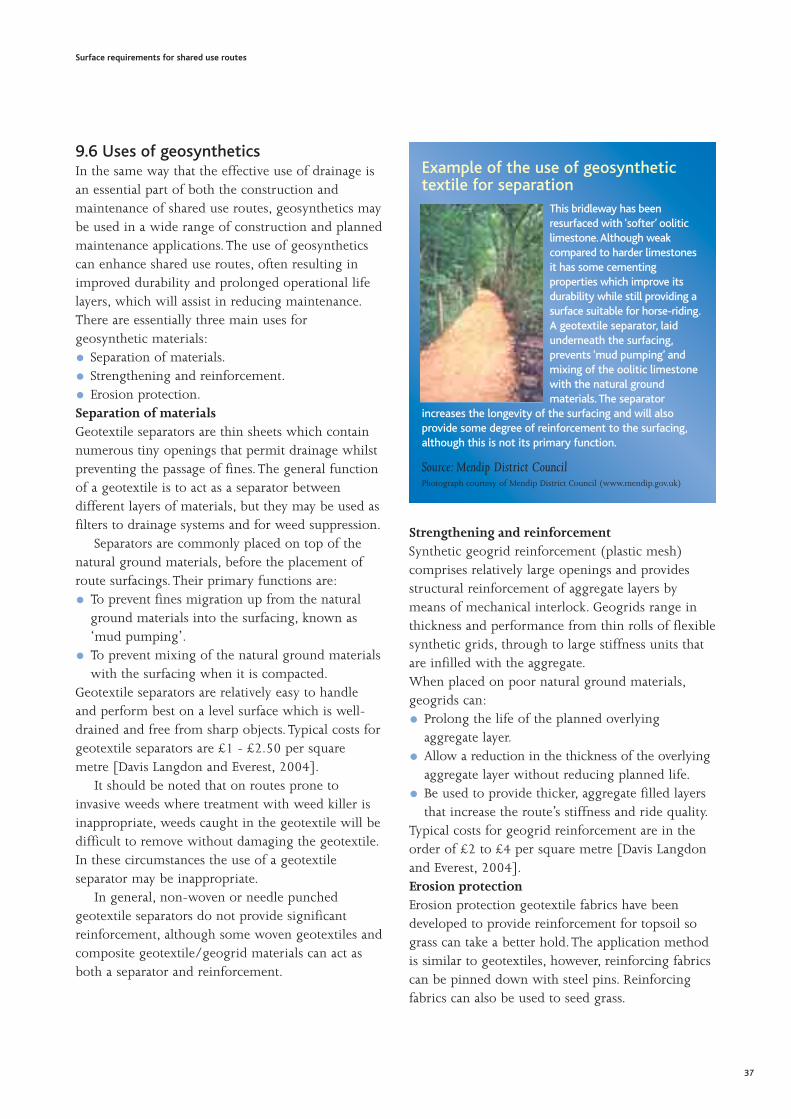
9.6 Uses of geosyntheticsIn the same way that the effective use of drainage isan essential part of both the construction andmaintenance of shared use routes, geosynthetics maybe used in a wide range of construction and plannedmaintenance applications.The use of geosyntheticscan enhance shared use routes, often resulting inimproved durability and prolonged operational lifelayers, which will assist in reducing maintenance.There are essentially three main uses forgeosynthetic materials:
• Separation of materials.
• Strengthening and reinforcement.
• Erosion protection.Separation of materialsGeotextile separators are thin sheets which containnumerous tiny openings that permit drainage whilstpreventing the passage of fines.The general functionof a geotextile is to act as a separator betweendifferent layers of materials, but they may be used asfilters to drainage systems and for weed suppression.
Separators are commonly placed on top of thenatural ground materials, before the placement ofroute surfacings.Their primary functions are:
• To prevent fines migration up from the naturalground materials into the surfacing, known as‘mud pumping’.
• To prevent mixing of the natural ground materialswith the surfacing when it is compacted.
Geotextile separators are relatively easy to handleand perform best on a level surface which is well-drained and free from sharp objects. Typical costs forgeotextile separators are £1 - £2.50 per squaremetre [Davis Langdon and Everest, 2004].
It should be noted that on routes prone toinvasive weeds where treatment with weed killer isinappropriate, weeds caught in the geotextile will bedifficult to remove without damaging the geotextile.In these circumstances the use of a geotextileseparator may be inappropriate.
In general, non-woven or needle punchedgeotextile separators do not provide significantreinforcement, although some woven geotextiles andcomposite geotextile/geogrid materials can act asboth a separator and reinforcement.
Strengthening and reinforcementSynthetic geogrid reinforcement (plastic mesh)comprises relatively large openings and providesstructural reinforcement of aggregate layers bymeans of mechanical interlock. Geogrids range inthickness and performance from thin rolls of flexiblesynthetic grids, through to large stiffness units thatare infilled with the aggregate.When placed on poor natural ground materials,geogrids can:
• Prolong the life of the planned overlyingaggregate layer.
• Allow a reduction in the thickness of the overlyingaggregate layer without reducing planned life.
• Be used to provide thicker, aggregate filled layersthat increase the route’s stiffness and ride quality.
Typical costs for geogrid reinforcement are in theorder of £2 to £4 per square metre [Davis Langdonand Everest, 2004].Erosion protectionErosion protection geotextile fabrics have beendeveloped to provide reinforcement for topsoil sograss can take a better hold.The application methodis similar to geotextiles, however, reinforcing fabricscan be pinned down with steel pins. Reinforcingfabrics can also be used to seed grass.
Surface requirements for shared use routes
37
Example of the use of geosynthetictextile for separation
This bridleway has beenresurfaced with ‘softer’ ooliticlimestone.Although weakcompared to harder limestonesit has some cementingproperties which improve itsdurability while still providing asurface suitable for horse-riding.A geotextile separator, laidunderneath the surfacing,prevents ‘mud pumping’ andmixing of the oolitic limestonewith the natural groundmaterials. The separator
increases the longevity of the surfacing and will alsoprovide some degree of reinforcement to the surfacing,although this is not its primary function.
Source: Mendip District CouncilPhotograph courtesy of Mendip District Council (www.mendip.gov.uk)

10.1 SummaryAppropriate surface construction should provide asuitable surface for all users. Surface construction isimportant for new shared use routes, but also has arole in planned maintenance, which often requiressome form of upgrade to the surface.This Section ofthe guide presents details of the sources of materials,and their use as surfacing materials. The initial focusof this Section is the options for reuse and recyclingof materials. The Section concludes with a discussionof unbound and sealed surfacings that can containrecycled materials if appropriate.
As route specific requirements will be influencedby local circumstances, only generic guidance can beprovided in this Guide. Indicative details on varioustypes of shared use route construction are providedin Appendix A.
10.2 Construction layersConventional construction of all shared use routesgenerally comprises up to three discrete layers:
• Surfacing layer or surface dressing – The topsurfacing layer in intimate contact with the user.Selection factors include appearance, smoothnessand durability.
• Sub-base layer – The structural part of the routeproviding strength to the construction andtransferring loads from the surface to theformation layer.
• Formation layer – The prepared ground on whichthe sub-base is laid.This may be the naturalground materials or a geosynthetic layer.
As a minimum guide, the depth of each layer shouldbe at least twice the size of the diameter of theaggregate used; for example, if using 20 mm gravelthen the minimum layer thickness is 40 mm [CSS,2005]. However, the required thickness for each ofthe layers will vary depending on:
• The type of surface construction, that is unboundor sealed.
• The traffic expected over the shared use route; forexample, a cycle track with high pedestrian andcycling traffic flows, or a bridleway with low trafficflows, but composed mostly of horse-riders.
10.3 Materials selectionAs a general principle, priority should be given tothe following hierarchy of use:1 The reuse of in situ materials, as this avoids the
environmental and financial costs of usingmaterial from non-renewable resources, itshaulage to site and the costs of disposal ofexcavated wastes.
2 The use of recycled materials, as this minimisesthe use of non-renewable resources.
3 The use of primary materials.It is important to recognise that local primarymaterials may be the most consistent with the localenvironment. In some instances, materials may beavailable at a nominal charge, or provided free by alandowner or maintainer; minimising the costs ofmaterial haulage.
Leaching from inappropriate materials candamage nature conservation interests, perhaps bychanging the pH of the surrounding area or byleaching heavy metals. Leaching of contaminants canoccur from any material, whether from non-renewable primary resources or recycled, locallysourced or imported resources. For example:
• Limestones can contain leachable lead.
• Limestone and cement can increase the pH of thesurrounding area.
• Cadmium and chromium are found in some slags.It is the concentrations of contaminants that areleached from the construction materials that areimportant, not the total levels of the contaminantspresent, as not all the contaminants will be availablefor leaching. An overview of leaching, specificallyrelated to recycled and secondary aggregates, can befound in the AggRegain ‘Environmental InformationSheet - Unbound aggregates used at or belowground level’ [AggRegain, 2004].
Surface requirements for shared use routes
38
10 Shared use surface construction

10.4 Reused materialsThere are various ways that materials may be reusedon a route. Existing prepared layers may be used,soil reversal or soil inversion, and the process of soil stabilization.
10.4.1 Railway corridorsMany shared use routes utilise old routes thatprovide pre-existing prepared formation and sub-base layers. The Sustrans publication ‘Making Waysfor the Bicycle’ provides details of shared use routeconstruction on railway corridors, and canaltowpaths [Sustrans, 1994].
10.4.2 Soil reversalSoil reversal or soil inversion (also known as‘machine dug’ paths) has proved to be verysuccessful in creating shared use routes across poorlydrained moorland or hill country, and in forests.
Suitable material is excavated from drainage ditchesto one or on both sides to form a raised surface,providing strength and improved drainage. Excavatedditches are lined with the excavated top soil andturfs to minimise visual impact. The profiles of suchditches can be softened to provide a range ofecological niches.
Soil reversal can provide a cost effective surfacefor most users. Its use is limited by the availablewidth of the route and the natural ground materials;it is not suitable for solid geology.The techniqueenables natural drainage to develop on one or bothsides of the route and does not rely on the use ofimported materials. However, soil reversal can causetemporary disruption to the route duringconstruction and requires the use of specialistexcavation plant. Further details on soilreversal/inversion are provided in Appendix A7.
Surface requirements for shared use routes
39
Example of reusedformer railway corridorThe Cuckoo Trail in East Sussex is ashared use route over a formerrailway corridor. The route is opento walkers, horse-riders andcyclists. The surfacing typicallycomprises a base course of 100 to150 mm thick rolled asphaltplanings or 40 mm scalpings, witha 20 mm thick surface oflimestone dust. The verges of theroute are built up 75 mm.
Source: British Horse SocietyPhotograph courtesy of Sustrans
(www.sustrans.org.uk)
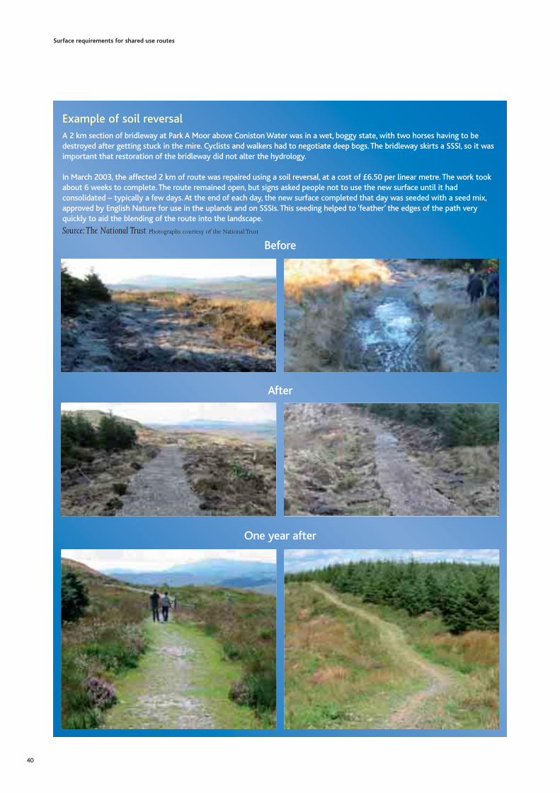
Surface requirements for shared use routes
40
Example of soil reversalA 2 km section of bridleway at Park A Moor above Coniston Water was in a wet, boggy state, with two horses having to bedestroyed after getting stuck in the mire. Cyclists and walkers had to negotiate deep bogs. The bridleway skirts a SSSI, so it wasimportant that restoration of the bridleway did not alter the hydrology.
In March 2003, the affected 2 km of route was repaired using a soil reversal, at a cost of £6.50 per linear metre. The work tookabout 6 weeks to complete. The route remained open, but signs asked people not to use the new surface until it hadconsolidated – typically a few days. At the end of each day, the new surface completed that day was seeded with a seed mix,approved by English Nature for use in the uplands and on SSSIs. This seeding helped to ‘feather’ the edges of the path veryquickly to aid the blending of the route into the landscape.
Source:The National Trust Photographs courtesy of the National Trust
Before
After
One year after

10.4.3 Stabilised materials Soil stabilisation is a technique to improve formationlayers so that they behave as sub-base layers. Thisavoids the need to import large volumes ofaggregates before the surfacing layer can be placed.
Alternatively, the stabilised formation layer canprovide a natural surface layer. As a surface layer itcan retain a reasonably natural appearance, althoughit may not be sufficiently robust enough forincreased user traffic. It is not necessarily a smoothsurface and may not be favoured by utility cyclists.
Stabilisation involves the intimate mixing of thesoil with a cementing binder, followed by wateringand compaction.The amount of binder, degree ofcompaction, nature of the soil and efficiency of themixing will determine the success of the technique.
Between 2% and 8% by weight of cement iscommonly used, which is rotovated into the toplayer, watered then compacted to finished levels. Claymay be treated in this way, although largerproportions of cement are needed. Alternatively, 2%to 5% by weight of lime can be used with clay,although the strength gain with lime is generallyslower than with cement. Alternative binders fromrecycled sources can be used, such as groundgranulated blast furnace slag or pulverised-fuel ash,as can polymeric admixtures.
Small-scale operations tend to involve surfacespreading of an appropriate binder on top of theground, before rotovation, watering andcompaction.The depth of mixing is generallyrestricted to a maximum of 150 mm.Limitations of the technique include:
• Suitability of the soil: It is not suitable for usewith high plasticity clays and organic soils or soils with an high sulphate content.
• The local ecology: Cement binders have a highpH and may be unsuitable in certain areas; forexample acid heathlands.
• Availability of water: Sufficient water is requiredfor the cementing reactions to occur without thematerial being too wet to compact.
• Temperature and weather:The colder thetemperature, the longer the cementing reactionstake.This could delay the time before the routecan be re-opened. Operations should besuspended during periods of rain and frost toprevent damage to the stabilised material.
• Construction planning: A maximum duration oftwo hours between spreading cement binder andthe final compaction of the material isrecommended and care should be taken to planthe works efficiently.
10.5 Recycled materialsRecycled aggregates are widely available acrossEngland and they should be used in preference tothe use of aggregates from non-renewable resources.The AggRegain website (www.aggregain.org.uk)contains a directory of suppliers of recycled andsecondary aggregates and should be consulted todetermine local availability.
However, although a recycled aggregate may havethe required technical properties for use in shareduse route, this does not infer environmental quality.The Environment Agency considers that waste whichis recycled as aggregate (such as crushed concrete orasphalt planings) only stops being waste when it isincorporated into a structure such as a road orbuilding, even if it has been through a recoveryprocess such as crushing or screening.This meansthat Waste Management Licensing applies to thetransport and handling of these materials.
However, ‘The Quality Protocol – for theproduction of aggregates from inert waste’ [WRAP,2004] sets out a quality production regime forreprocessing of materials, after which the materialis “probably” no longer a waste. This QualityProtocol was produced jointly with theEnvironment Agency. This means that recycledaggregates produced using a quality regime can betransported and handled in the same way asaggregates from non-renewable resources.
Surface requirements for shared use routes
41

10.5.1 Recycled asphaltRecycled asphalt is suitable for use in shared useroutes. However, recycling into new road asphalt is amore appropriate and sustainable option if localrecycling facilities are available. It is possible that theuse of recycled asphalt at the surface of a shared useroute will be aesthetically inappropriate, as it givesthe route an ‘urban’ feel.
Modern asphalts are made with bitumen ratherthan tar, and thus are inert and suitable for recycling.However, it is possible that some road planings,particularly those from old roads, may contain tar.Hence, the provenance of any materials should beestablished before they are used.
10.5.2 Crushed concrete and brickQuality controlled crushed concrete and brickprovide a highly durable sub-base layers appropriatefor multi-use routes and can be cost effective ifavailable locally. However, both materials maycontain lime and may not be suitable for pHsensitive environments. Crushed concrete is alsosuitable for use as an aggregate in higher valueapplications, such as an aggregate in asphalt or newconcrete.These recycling options should bepreferred in locations where appropriate recyclingfacilities exist. Further information on recyclingfacilities and their intake materials can be found at:
• http://www.ciria.org/recycling
• http://www.smartwaste.co.uk/bremap.jsp
10.5.3 Quarry wastesQuarry wastes can provide a good source ofsurfacing materials. Limestone dust is used widely asa surface dressing. Its fine size and cementingproperties provide a smooth, strengthened surface.However, it can be susceptible to frost heave andmay not be robust in the long-term. It is known towear at an approximate rate of 3 mm per year andrequires regular renewal. It can also be sharpunderfoot and unsuitable for horses. As a naturallyalkaline material, it should only be used in areaswith appropriate background pH levels.
Surface requirements for shared use routes
42
Phot
ogra
ph c
ourt
esy
of D
evon
Cou
nty
Cou
ncil
(ww
w.d
evon
.gov
.uk)
Example of recycled asphalt surfacing
Examples of use of recycled asphaltplaningsFor many years the Three Points Lane Bridleway,Buckinghamshire, was heavily waterlogged all year roundand overgrown, making it difficult to use. In 2004,Buckinghamshire County Council used several tons ofloosely compacted road planings to upgrade the route.The new surface is user friendly for walkers, cyclists andhorse-riders, and blends in with the locality.Source: Ramblers’AssociationLeicestershire County Council completed the resurfacingof 1.2 km of 3 m wide route using 200 mm of recycledasphalt compacted over a geosynthetic membrane,topped with 25 mm of granite dust. The recycled asphaltwas £1 per tonne less than the alternative from non-renewable sources. Similarly built routes constructedabout 3 years previously are in good condition.Source: Cheshire County Council [Cheshire County Council, 2004]
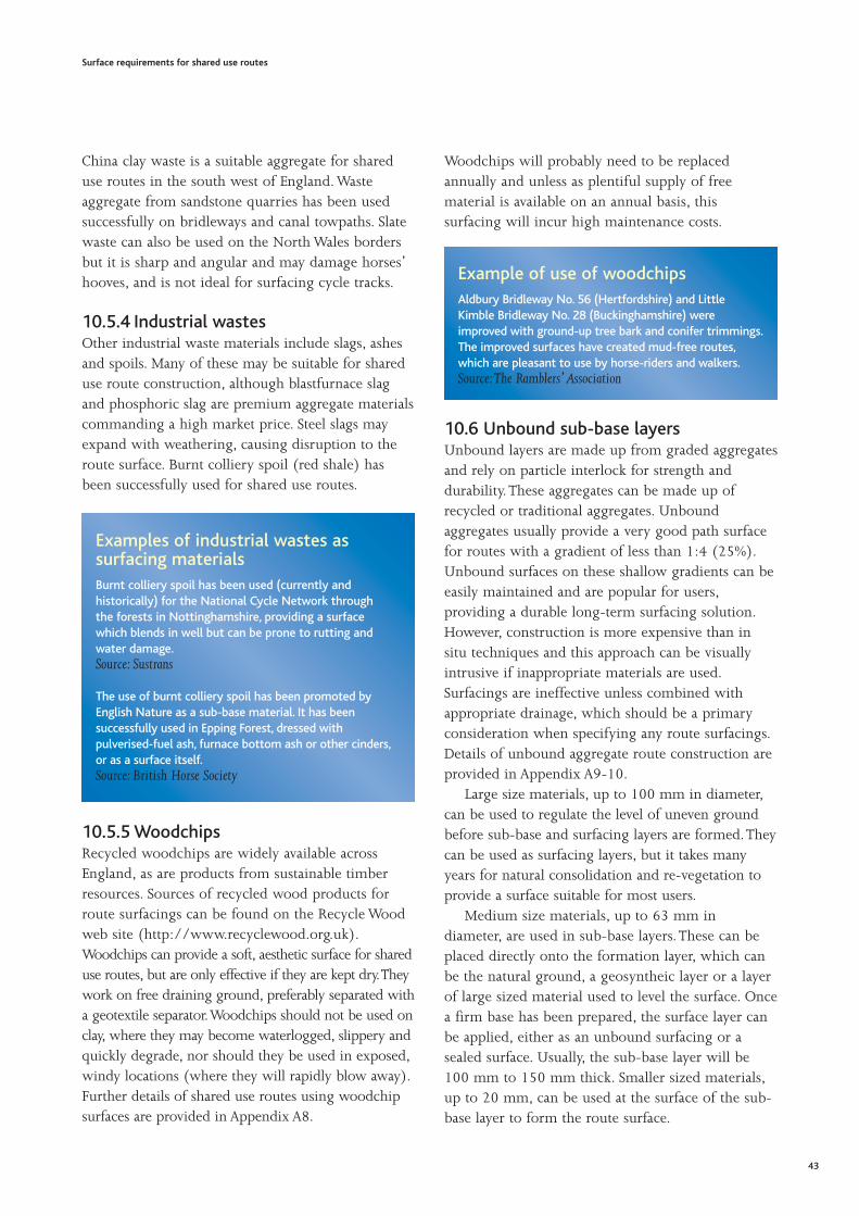
China clay waste is a suitable aggregate for shareduse routes in the south west of England. Wasteaggregate from sandstone quarries has been usedsuccessfully on bridleways and canal towpaths. Slatewaste can also be used on the North Wales bordersbut it is sharp and angular and may damage horses’hooves, and is not ideal for surfacing cycle tracks.
10.5.4 Industrial wastesOther industrial waste materials include slags, ashesand spoils. Many of these may be suitable for shareduse route construction, although blastfurnace slagand phosphoric slag are premium aggregate materialscommanding a high market price. Steel slags mayexpand with weathering, causing disruption to theroute surface. Burnt colliery spoil (red shale) hasbeen successfully used for shared use routes.
10.5.5 WoodchipsRecycled woodchips are widely available acrossEngland, as are products from sustainable timberresources. Sources of recycled wood products forroute surfacings can be found on the Recycle Woodweb site (http://www.recyclewood.org.uk).Woodchips can provide a soft, aesthetic surface for shareduse routes, but are only effective if they are kept dry.Theywork on free draining ground, preferably separated witha geotextile separator.Woodchips should not be used onclay, where they may become waterlogged, slippery andquickly degrade, nor should they be used in exposed,windy locations (where they will rapidly blow away).Further details of shared use routes using woodchipsurfaces are provided in Appendix A8.
Woodchips will probably need to be replacedannually and unless as plentiful supply of freematerial is available on an annual basis, thissurfacing will incur high maintenance costs.
10.6 Unbound sub-base layersUnbound layers are made up from graded aggregatesand rely on particle interlock for strength anddurability.These aggregates can be made up ofrecycled or traditional aggregates. Unboundaggregates usually provide a very good path surfacefor routes with a gradient of less than 1:4 (25%).Unbound surfaces on these shallow gradients can beeasily maintained and are popular for users,providing a durable long-term surfacing solution.However, construction is more expensive than insitu techniques and this approach can be visuallyintrusive if inappropriate materials are used.Surfacings are ineffective unless combined withappropriate drainage, which should be a primaryconsideration when specifying any route surfacings.Details of unbound aggregate route construction areprovided in Appendix A9-10.
Large size materials, up to 100 mm in diameter,can be used to regulate the level of uneven groundbefore sub-base and surfacing layers are formed.Theycan be used as surfacing layers, but it takes manyyears for natural consolidation and re-vegetation toprovide a surface suitable for most users.
Medium size materials, up to 63 mm indiameter, are used in sub-base layers. These can beplaced directly onto the formation layer, which canbe the natural ground, a geosyntheic layer or a layerof large sized material used to level the surface. Oncea firm base has been prepared, the surface layer canbe applied, either as an unbound surfacing or asealed surface. Usually, the sub-base layer will be100 mm to 150 mm thick. Smaller sized materials,up to 20 mm, can be used at the surface of the sub-base layer to form the route surface.
Surface requirements for shared use routes
43
Examples of industrial wastes assurfacing materialsBurnt colliery spoil has been used (currently andhistorically) for the National Cycle Network through the forests in Nottinghamshire, providing a surface which blends in well but can be prone to rutting andwater damage.Source: Sustrans
The use of burnt colliery spoil has been promoted byEnglish Nature as a sub-base material. It has beensuccessfully used in Epping Forest, dressed withpulverised-fuel ash, furnace bottom ash or other cinders,or as a surface itself.Source: British Horse Society
Example of use of woodchipsAldbury Bridleway No. 56 (Hertfordshire) and LittleKimble Bridleway No. 28 (Buckinghamshire) wereimproved with ground-up tree bark and conifer trimmings.The improved surfaces have created mud-free routes,which are pleasant to use by horse-riders and walkers.Source:The Ramblers’Association

The sub-base layer must be effectively compactedand levelled to good longitudinal profile and ridequality.The surface of the sub-base layer should beprofiled to shed water, by providing either a crossfallor camber (see Appendix A1). Crossfall or cambershould be checked using a camber board before thesurfacing layers are applied.
10.7 Unbound surface layersSurfacing layers should provide adequate cover tothe sub-base layer, so that the route surface remainseven. Usually an absolute minimum of 25 mm isrequired. A range of unbound surfacings areavailable including:
• Blinding
• Hoggin
• Stone
10.7.1 BlindingSand or dust sized material is used to provide asmooth surface for a route. It can be prone torutting, and requires regular regrading (raking).These surfacings may not be suitable for routes thatcarry cyclists, wheelchairs or pushchairs, unless theblinding layer has some degree of binding, forexample through natural cementing properties orthe presence of clay. Without some bindingproperties, there may be a tendency for thesesurfacings to be dusty when dry.
Surface requirements for shared use routes
44
Example of sub-base layer surfacingOne part of the surfacing of Byway 49 in Chieveleycomprises fine gravel on a firm base. The original routewas diverted from the definitive line in the 1990s, as aresult of the development of a sand and gravel quarrynear Newbury. The new route surface was provided withmaterial supplied by the quarry, forming an excellentsurface for walkers, cyclists and equestrians. The surface issoft and kind to horses and walkers, as it reducesconcussion and helps maintain reasonable cycling speeds.It is not too soft to encourage fast horse-riding, either. Thesurface drains well and is quite firm and stable where it isunderlain by sand. Part of the track is on a slope but thisdoes not seem to cause any loss of surfaceSource: British Horse Society,West Berkshire
Examples of blinding as a surfacingThe Green Crescent is a shared use route for walkers,cyclists and riders which skirts around the western side ofBurgess Hill. It delimits the edge of the town from theadjacent countryside and villages. These pictures show asection of the routes made up from a sub-base layerblinded with 3 mm to dust limestone fines. Thisspecification will be used on further phases of the GreenCrescent project.Photographs courtesy of Mid Sussex District Council(www.midsussex.gov.uk)

10.7.2 HogginThis is a general term for material usuallycomprising rounded gravel with relatively high finescontent. If the fines content is too high, then thematerial will be prone to softening and ruttingwhen wet. Hoggin binds well when rolled andforms a firm surface. Hoggin can be very variableand its quality and consistency should be monitoredduring construction [British Horse Society, 1995].
10.7.3 StoneStone surfacing is visually attractive, with long-termdurability and low maintenance, making it ideal forremote routes. Stone flagging and stone pitching aretraditional techniques popular in areas with solidground, where the stone is gathered locally and isvisually unobtrusive. Although stone can beexpensive to transport, particularly to remotelocations, its durability, aesthetic qualities andreduced maintenance costs, compared to othersurfacings, may reduce the whole life costs of thestone surfacing. Extensive details on both surfacingtechniques are contained in ‘Repairing Upland PathErosion – A Best Practice Guide’ [Davies et al, 1996].
Routes may need to be closed while work isundertaken, and this may be for several months. Ideally,the stone is gathered locally and consistent with thelocal geology so that it is not visually intrusive.
Stone flagging uses large flat stones on shallowgradients, often to float over peaty or boggy ground.
The best practice guide ‘Repair of Upland PathErosion’ notes that stone flagging is a regionaltechnique which is probably inappropriate outside thePennine and Yorkshire Districts [Davies et al, 1996].
Stone pitching involves placing large stones, withtheir flattest side up, to create small irregular stepswhich blend into the landscape. Pitching iscommonly used for routes on steeper gradients,above 1:4 (25%), incorporating curves and naturalrocky feature to help the route blend with thelandscape. Once laid, any small gaps are infilled withsoil. This soil is fertilised and seeded, to promote anatural appearance. Fertilising and seeding theground either side of the route helps the surfacingto blend into the landscape and also to keep users onthe route. Further details on the use of stonepitching are provided in Appendix A11.
Surface requirements for shared use routes
45
Fittleworth stoneFittleworth stone, a fine-graded local stone, has also beenused as a blinding for short sections of the route, inNightingale Lane Meadows, the most southerly part of theGreen Crescent. It performs reasonably well as a surfacing,is visually pleasing and is not too jarring for users.However, the stone is liable to be picked up on shoes andhooves after a frost.Fittleworth stone needs to be kept proud of the ground;therefore, edgings have been dispensed with and the routewas constructed above the ground rather than byexcavating. The camber of the route is very good, allowingsurface water to be shed, with good drainage channels laidalongside.Source: Mid Sussex District Council and Mid Sussex AreaBridleways Group
Two examples of pitched stone surfacings
Photograph courtesy of the National Trust(www.nationaltrust.org.uk)
Photograph courtesy of Scott Wilson Pavement Engineering(www.swpe.co.uk)

10.8 Floating pathsFloating paths are used on soft ground with highgroundwater levels. They use natural separators, suchas brushwood or geosynthetic materials as theformation layer to provide a ‘buoyant’ raft for thesub-base and surfacing. Even without seeding, thistype of route may green naturally if the level of useis not too high. Flagstones can be placed without aseparator as they ‘float’ on the soft ground.
Floating paths can provide cost effective shareduse routes. Although installation requires only lowskill levels, it can be labour intensive.They can besustainable if they use local materials and are able towithstand maintenance access. Further details onfloating paths are provided in Appendix A12.
10.9 Sealed surfacesSealed surfaces are more durable than unboundsurfaces as the use of a cement or bitumen bindercontains the aggregate and maintains the integrity ofthe surface.They can provide a cost effective surfacefor shared use routes, particularly utility routes inboth urban and rural environments. Further detailsof asphalt surfaces are provided in Appendix A13-14.
Sealed surfaces are a robust, proven, long-termsolution and relatively easy to maintain by regularsweeping.This low maintenance should beconsidered as part of the whole life costing of theroute. Asphalt (also known as bituminous macadamor ‘bitmac’) is strong and durable with bituminoussurfaces lasting for more than 20 years. Concretesurfaces are also durable and can last in excess of 40years. However, concrete is susceptible to frost attackif the surface if not properly constructed. Bothasphalt and concrete surfacings should be machinelaid on cycle routes, to ensure adequate longitudinalprofile and ride quality is achieved.
Sealed surfaces may not have the requiredaesthetic appearance to match the local landscape.This might be overcome by planting to obscure theroute from scenic views. In general, sealed surfacesare rigid and not preferred by horse-riders andmany runners, although they may be appropriate foruse on short sections where routes cross vehicularaccess points. Sealed surfaces can be acceptablewhere a large grassy verge is available. Asphaltsurfaces can be intrinsically slippery or becomeslippery when wet and covered in decayingvegetation.
10.9.1 Surface dressingSurface dressing, also known as bitumen spray andchip, can be used to treat slippery sealed surfacesand can be cost effective for maintenance. It providesa compromise, providing a visually acceptable,natural aggregate appearance which wears wellcompared to unbound surfacings.The advantage ofsurface dressing is that the aggregate chips can beselected to suit both the local circumstances andlocal character. It is a much lower cost than asphaltsurfacing but must be placed on a well compactedsub-base layer.
Surface dressing involves spraying bitumen overan existing surface (which may be sealed or anunbound surface) and rolling fine gravel chips toform a textured surface. Surface dressing can be laidby hand where space is compromised.The surfacedressing should be swept after placing to removeexcess, loose stones which can be a hazard to users.
Surface requirements for shared use routes
46
Example of a floating pathFloating paths form part of a shared use route fromKielder to Newcastleton through Kielder Forest and intoKershope Forest. It is much used by cyclists, althoughless so by horse-riders and walkers. The path in thephotograph was constructed in the 1980s and is nowmore stable and is covered with more vegetation. It issuitable for horses to canter.Source: British Horse Society, North of England
Photograph courtesy of courtesy of Sue Rogers

Two forms of surface dressing widely used, ‘single’and ‘racked in’, shown below [TRL, 2002]. Singlesurface dressing involves a spray of bitumen andsingle layer of aggregate chips.These dressings aresufficiently robust for most situations. Racked insurface dressings use 10% less chips, and a thickerbitumen coating than a single surface dressing.Smaller chips are used to infill between the largerchips, increasing the stability of the surfacing.
The sub-base layer will need to provide the crossfallor camber needed to shed water from the route.Surface dressing can last between 10 and 15 years, ifthe layer is appropriately placed and the structure isresistant to frost heave. It will loose its chippingsunder very heavy traffic, and the bitumen layerexposed will be slippery when wet. Further detailsof surface dressing are provided in Appendix A12.
Proprietary surface dressings containing glassfibre reinforcement have been used on shared useroutes. A bitumen binder with glass reinforcement islaid, and then aggregates rolled into the surfacing.The glass fibre reinforcement enhances the crack andfatigue resistance of the surfacing.
Surface requirements for shared use routes
47
Single surface dressing
Racked in surface dressing
The information in the following surfacing details is indicative only and not intended to be relied upon in specific cases. Pricing information is also onlyindicative and current at time of publication and should not be used for detailed pricing estimates. The Countryside Agency and Scott Wilson PavementEngineering Limited accept no liability for any inaccuracies nor for any loss, expense or damage arising from the use or application of such information.

Agate, E. (1996), Footpaths, A Practical Handbook, British Trustfor Conservation Volunteers. Available athttp://handbooks.btcv.org.uk.
AggRegain (2004), Environmental Information Sheet - Unboundaggregates used at or below ground level [online]. Last Accessed26 June 2005 at http://www.wrap.org.uk
British Horse Society (1995), Guide to the Surfacing ofBridleways and Horse Tracks, 2nd Edition.
Countryside Agency (2000), Greenways Handbook [online]. Lastaccessed 23 June 2005 at http://www.greenways.gov.uk
Countryside Agency (2001), CRN32 - How people interact onoff-road routes. Available online athttp://www.countryside.gov.uk
Countryside Agency (2003a), A guide to definitive maps andchanges to public rights of way. Available online athttp://www.countryside.gov.uk
Countryside Agency (2003b), CRN69 - How people interact onoff-road routes: Phase II. Available online athttp://www.countryside.gov.uk
Countryside Agency (2005a), Managing public access – a guidefor land managers. Available online athttp://www.countryside.gov.uk
Countryside Agency (2005b), By All Reasonable Means: Inclusiveaccess to the outdoors for disabled people. Available online athttp://www.countryside.gov.uk
CSS (2005), Countryside Working Group Report on theSurfacing of Bridleways. Available online at http://cssnet.org.uk
Davies, P., Loxham, J. and Huggon, G. (1996), Repairing UplandPath Erosion – A Best Practice Guide, Lake District National ParkAuthority, National Trust and English Nature.
Davis Langdon and Everest, Spon’s Civil Engineering andHighway Works Price Book 2004.
DEFRA 2005, Making the Best of Byways – Apractical guide forLocal Authorities managing and maintaining byways whichcarry motor vehicles, Second Edition (to be published).
DfT (1990), Traffic Advisory Leaflet 4/90: Tactile Markings forSegregated Shared Use by Cyclists and Pedestrians.
DfT (2004a), Policy, Planning and Design for Walking andCycling (Draft for consultation). Available online at:http://www.dft.gov.uk
DfT (2004b), Adjacent and Shared Use Facilities for Pedestriansand Cyclists. (Draft for consultation). Available online at:http://www.dft.gov.uk
HM Government (2005), Securing the future delivering UKsustainable development strategy. Available online at:http://www.sustainable-development.gov.uk
LDNPA (Undated), Footpath Erosion Factsheet. Available onlineat http://www.lake-district.gov.uk
Scottish National Heritage, Scottish Enterprise and The Pathsfor All Partnership (2001), Lowland Path Construction – A Guideto Good Practice.
Senate Department for Urban Development (1993), BerlinDigital Environmental Atlas - 01.02 Sealing of Soil Surface(Edition 1993) [online]. Last accessed 25 June 2005 athttp://www.stadtentwicklung.berlin.de
Sustrans (1994), Making Ways for the Bicycle. Available onlineat http://www.sustrans.org.uk
Sustrans (1997), National Cycle Network - Guidelines andPractical Details Issue 2. Available online athttp://www.sustrans.org.uk
Sustrans (1999) FF27 Ways through the countryside. Producedin conjunction with the ramblers & BHS. Available online athttp://www.sustrans.org.uk
Sustrans (2000), Information Sheet FF04 - Shared Use Routes.Available online at http://www.sustrans.org.uk
Riddall and Trevelyan (2001), Rights of Way – a guide to lawand practice, Third Edition, Open Spaces Society and Ramblers’Association.
TRL (2002), Design guide for road surface dressing, Road Note 39.
WRAP (2004), The Quality Protocol - for the production ofaggregates from inert waste. Available online athttp://www.aggregain.org.uk
Surface requirements for shared use routes
48
10 References

These indicative details appear in this Appendix inthe same order in which they are referred to withinthe Guide.The layers shown in Figure 1 are referred tothroughout this Appendix.These are discussed inSection 10.2 for the Guide.
Figure 1:
Schematic diagram of construction layers in a shared use route
This Appendix contains material specifications,general construction details, indicative material costsand indicative maintenance requirements for thefollowing aspects of shared use routes:A1. Crossfall and camber
A2. Pothole repair
A3. Grassed gravel surfacing
A4. Open ditch drainage
A5. Filter drainage
A6. Culvert drainage
A7. Soil reversal
A8. Wood-chip surfacing
A9. Unbound aggregate surfacing - 1
A10. Unbound aggregate surfacing - 2
A11. Stone pitching surfacing
A12. Floating path construction
A13. Sealed bituminous surface - 1
A14. Sealed bituminous surface - 2
Surface requirements for shared use routes
49
Appendix A Indicative Surfacing Details
Surfacinglayer
Sub-baselayer
Formationlayer
The information in the following surfacing details is indicative only and not intended to be relied upon in specific cases. Pricing information is also onlyindicative and current at time of publication and should not be used for detailed pricing estimates. The Countryside Agency and Scott Wilson PavementEngineering Limited accept no liability for any inaccuracies nor for any loss, expense or damage arising from the use or application of such information.

A1 Crossfall and Camber
Indicative construction/ maintenance details
• Cambers are ideally used on flat, poorly drained areas, where the surface of the route is raised and angled to allow water tobe run off to adjacent ‘off route’ drainage.
• Crossfalls are commonly used where the natural drainage does not suit a camber, or on bends where the radius of curvatureis small.
• Crossfalls are easier to construct than cambers. The crossfall sheds water in the direction of natural drainage.
• Cambers are preferred to crossfalls by cyclists, pushchair and wheelchair users. The maximum recommended crossfall orcamber for non-motorised wheelchair users is 1:50 (2%), but on narrow routes, higher crossfalls and cambers will be needed to shed water effectively.
• Preferably, use a minimum camber of 1:40 (2.5%) on a 2 m wide route, providing a drop of 25 mm. This increases tominimum of 1:20 (5%) for a 3 m wide route, giving a drop of 75 mm.
• Minimum crossfall should be 1:40 (2.5%), with 1:20 (5%) preferable.
• Construction or maintenance of cambers and crossfalls is less than £5 per linear metre for a 2.5 m wide route.
References
• County Surveyors Society Countryside Working Group, Report on the Surfacing of Bridleways, 2005.
• Scottish National Heritage, Scottish Enterprise and The Paths for All Partnership, Lowland Path Construction – A Guide toGood Practice, 2001.
Surface requirements for shared use routes
50
Surfacinglayer
Surfacinglayer
Formation layer
Sub-baselayer
Sub-baseSub-baselalayyerer
Crossfall - 1:40 (2.5%)
Formation layer
Sub-baselayer
Sub-baseSub-baselalayyerer
1:40 (2.5%) 1:40 (2.5%)
The information in the following surfacing details is indicative only and not intended to be relied upon in specific cases. Pricing information is also onlyindicative and current at time of publication and should not be used for detailed pricing estimates. The Countryside Agency and Scott Wilson PavementEngineering Limited accept no liability for any inaccuracies nor for any loss, expense or damage arising from the use or application of such information.

A2 Pothole Repair
Material specification
• Backfill material – sub-base grade material, typically 63 mm down.
• Surfacing layer – in keeping with the existing surfacing.
General construction details
• Undertake full depth repairs only.
• Work should only be undertaken in dry weather, and any excavated area should be dry before backfilling.
• Excavate the pothole to the full depth of sub-base layer. The sides of the excavation section should be straight.
• Fill with backfill material and compact in place.
• Reapply surfacing.
Indicative material costs
• Costs will vary depending upon the size of the pothole and the surfacing material.
• Backfill material is between £10 and £13 per tonne.
• 20 mm thickness quarry fines (5 mm to dust) can be used to replace an unbound surface or as a temporary reinstatement ofa sealed surface. Quarry wastes cost between £7 and £10 per tonne.
Indicative maintenance requirements
• Inspect regularly (for example, monthly).
• Repair as required, ideally on an annual basis.
• Ensure repairs are completed before the winter to prevent further deterioration of the pothole and the route.
References
• County Surveyors Society Countryside Working Group, Report on the Surfacing of Bridleways, 2005.
• Davis Langdon and Everest, Spon’s Civil Engineering and Highway Works Price Book 2004.
Surface requirements for shared use routes
51
Surfacinglayer
Sub-baselayer
Formationlayer
Area forexcavation
Pothole
The information in the following surfacing details is indicative only and not intended to be relied upon in specific cases. Pricing information is also onlyindicative and current at time of publication and should not be used for detailed pricing estimates. The Countryside Agency and Scott Wilson PavementEngineering Limited accept no liability for any inaccuracies nor for any loss, expense or damage arising from the use or application of such information.

A3 Grassed Gravel Surfacing
Material specification
• Geosynthetic for strengthening or separation, if required.
• Sub-base aggregate - for example, 63 mm down.
• Topsoil - conforming to BS 3882: 1994.
• Grass seed - approved by an ecologist and preferably trampling resistant.
General construction details
• Excavate to a minimum 150 mm below existing ground level.
• Place and secure the geosynthetic, if used.
• Place and compact the sub-base aggregate to a minimum thickness of 200 mm. Ensure that the compacted sub-base is atleast 50 mm above the existing ground level.
• Provide a crossfall or camber (see Appendix A1).
• Place 25 mm thickness of topsoil over the sub-base. Mix into the prepared sub-base to a depth of 100 mm, using a harrow orrotovator, or a machine excavator bucket.
• Seed the surface and gently roll.
Indicative material costs
• Sub-base aggregate costs between £10 and £13 per tonne.
• If possible, the topsoil should be reused from excavated arisings. Imported topsoil costs approximately £10 per cubic metre.
• Grass seed mixtures cost between £70 and £85 for a 25 kg bag.
Indicative maintenance requirements• Ideally, the grassed surface should be allowed to develop before the route is re-opened for shared use. Maintenance includes
reseeding if necessary, preferably carried out in spring.
• Temporary restriction on use may be required for a short period, for example, after prolonged adverse weather, to allow thegrass to re-establish.
References
• British Horse Society, Guide to the Surfacing of Bridleways and Horse Tracks, 2nd Edition, 1995.
• British Standards Institution, BS 3882: Specification for topsoil, 1994.
• Countryside Agency, Pennine Bridleway National Trail Specification, 1999.
• Davis Langdon and Everest, Spon’s Civil Engineering and Highway Works Price Book 2004.
Surface requirements for shared use routes
52
25 mmtopsoil
100 mm deeptopsoil and sub-base
mixing zone
200 mmcompactedsub-base
150 mmexcavation
belowexcistingground
level
50mm sub-baseabove existingground level
Geosynthetic
The information in the following surfacing details is indicative only and not intended to be relied upon in specific cases. Pricing information is also onlyindicative and current at time of publication and should not be used for detailed pricing estimates. The Countryside Agency and Scott Wilson PavementEngineering Limited accept no liability for any inaccuracies nor for any loss, expense or damage arising from the use or application of such information.

A4 Open Ditch Drainage
General construction details
• Using a suitable excavator, excavate the open ditch within the space available adjacent to route.
• Leave a minimum of 0.3 m, preferably 0.5 m, wide verges between ditch and route.
• Leave wider verges if there is more space available or if the verge is a dual surfacing for a segregated route.
• Excavate the ditch to provide the necessary capacity. Ditches should be used on routes with a minimum gradient between1:15 (6.5%) and 1:50 (2%).
• Drainage ditches are typically between 0.3 m and 0.5 m deep, with the width of the opening twice the width of the base, asshown.
• Swales may be 0.3 m to 0.5 m deep, and 1.5 m to 2 m wide.
• For drainage ditches and swales, the ditch bed should be smooth.
Indicative maintenance requirements
• Clear open ditches of vegetation, litter and silt at least twice a year, preferably during the autumn and the spring.
• Clearance costs between £0.50 and £1.00 per linear metre, depending on ditch dimensions and conditions.
References
• Countryside Agency, Pennine Bridleway National Trail Specification, 1999.
• Scottish National Heritage, Scottish Enterprise and The Paths for All Partnership, Lowland Path Construction – A Guide toGood Practice, 2001.
Surface requirements for shared use routes
53
1000 mm
300 mm
500 mm Deep Ditch
600 mm
150 mm
300 mm Deep Ditch
30
0 m
m
50
0 m
m
The information in the following surfacing details is indicative only and not intended to be relied upon in specific cases. Pricing information is also onlyindicative and current at time of publication and should not be used for detailed pricing estimates. The Countryside Agency and Scott Wilson PavementEngineering Limited accept no liability for any inaccuracies nor for any loss, expense or damage arising from the use or application of such information.

A5 Filter Drainage
Surface requirements for shared use routes
54
100 mm
550 mm
Porouspipe
Geotextile
Drainbackfill
Excavatedmaterial
450 mm
Depthvaries
150 mm
All dimensions areindicative and should
not be relied on inspecific instances
300 mm
Shared useroute
The information in the following surfacing details is indicative only and not intended to be relied upon in specific cases. Pricing information is also onlyindicative and current at time of publication and should not be used for detailed pricing estimates. The Countryside Agency and Scott Wilson PavementEngineering Limited accept no liability for any inaccuracies nor for any loss, expense or damage arising from the use or application of such information.

A5 Filter Drainage continued
Material specification
• Perforated PVC pipe – the internal diameter of the pipe should be selected to ensure sufficient drainage capacity is provided.
• Drainage backfill – clean aggregate between 20 and 40 mm size.
• Appropriate filter geotextile – the asparity of the geotextile is dependent on the grading of the surrounding natural groundmaterial.
General construction details
• Excavate the drainage trench to the required dimensions. The ditch width should be 450 mm more than the internaldiameter of the pipe.
• Where possible, the trench should be a minimum of 300 mm from the edge of the route. Filter drainage should be used onroutes with a minimum gradient between 1:15 (6.5%) and 1:50 (2%).
• Line the trench base and sides with filter geotextile, leaving a minimum of 450 mm overlap at the top of the trench,
• Lay the pipe and backfill to within 150 mm of surface.
• Overlap the geotextile and backfill remaining 150 mm depth with additional drainage backfill or excavated arisings.
• Catch pits should be included at bends, junctions and at 30 m intervals.
Indicative material costs
• A 100 mm internal diameter pipe costs approximately £6 for a 6 m pipe length.
• A 150 mm internal diameter pipe costs approximately £12 for a 6 m pipe length.
• Drainage backfill material costs between £8 and £17 per tonne, depending on grading and location.
• Geotextiles cost between £1 and £2.50 per square metre.
Indicative maintenance requirements
• Every 6 months, pipes should be rodded, and silt and vegetation removed from catchpits. This is usually conducted everyautumn and spring.
• Rodding and catchpit clearance costs between £5 and £10 per catchpit.
References
• Countryside Agency, Pennine Bridleway National Trail Specification, 1999.
• Davis Langdon and Everest, Spon’s Civil Engineering and Highway Works Price Book 2004.
• Scottish National Heritage, Scottish Enterprise and The Paths for All Partnership, Lowland Path Construction – A Guide toGood Practice, 2001.
Surface requirements for shared use routes
55
The information in the following surfacing details is indicative only and not intended to be relied upon in specific cases. Pricing information is also onlyindicative and current at time of publication and should not be used for detailed pricing estimates. The Countryside Agency and Scott Wilson PavementEngineering Limited accept no liability for any inaccuracies nor for any loss, expense or damage arising from the use or application of such information.
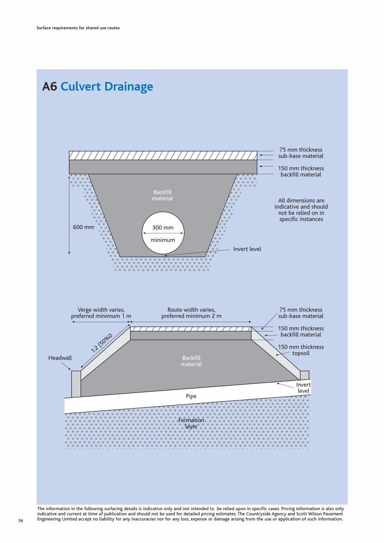
Surface requirements for shared use routes
A6 Culvert Drainage
56
Formationlayer
Pipe
Backfillmaterial
Headwall
Route width varies,preferred minimum 2 m
Verge width varies,preferred minimum 1 m
75 mm thicknesssub-base material
150 mm thicknessbackfill material
150 mm thicknesstopsoil
Invertlevel
1:2(5
0%0
75 mm thicknesssub-base material
150 mm thicknessbackfill material
Invert level
600 mm 300 mm
minimum
All dimensions areindicative and should
not be relied on inspecific instances
Backfillmaterial
The information in the following surfacing details is indicative only and not intended to be relied upon in specific cases. Pricing information is also onlyindicative and current at time of publication and should not be used for detailed pricing estimates. The Countryside Agency and Scott Wilson PavementEngineering Limited accept no liability for any inaccuracies nor for any loss, expense or damage arising from the use or application of such information.
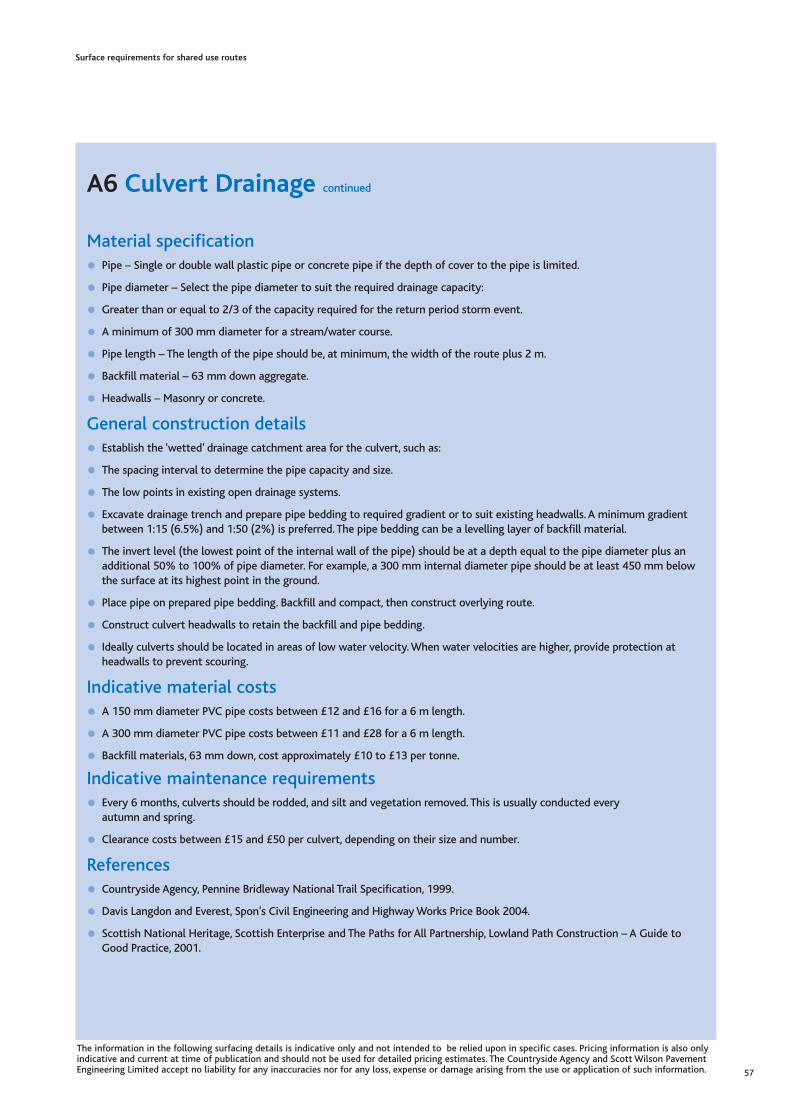
Surface requirements for shared use routes
A6 Culvert Drainage continued
Material specification
• Pipe – Single or double wall plastic pipe or concrete pipe if the depth of cover to the pipe is limited.
• Pipe diameter – Select the pipe diameter to suit the required drainage capacity:
• Greater than or equal to 2/3 of the capacity required for the return period storm event.
• A minimum of 300 mm diameter for a stream/water course.
• Pipe length – The length of the pipe should be, at minimum, the width of the route plus 2 m.
• Backfill material – 63 mm down aggregate.
• Headwalls – Masonry or concrete.
General construction details
• Establish the ‘wetted’ drainage catchment area for the culvert, such as:
• The spacing interval to determine the pipe capacity and size.
• The low points in existing open drainage systems.
• Excavate drainage trench and prepare pipe bedding to required gradient or to suit existing headwalls. A minimum gradientbetween 1:15 (6.5%) and 1:50 (2%) is preferred. The pipe bedding can be a levelling layer of backfill material.
• The invert level (the lowest point of the internal wall of the pipe) should be at a depth equal to the pipe diameter plus anadditional 50% to 100% of pipe diameter. For example, a 300 mm internal diameter pipe should be at least 450 mm belowthe surface at its highest point in the ground.
• Place pipe on prepared pipe bedding. Backfill and compact, then construct overlying route.
• Construct culvert headwalls to retain the backfill and pipe bedding.
• Ideally culverts should be located in areas of low water velocity.When water velocities are higher, provide protection atheadwalls to prevent scouring.
Indicative material costs
• A 150 mm diameter PVC pipe costs between £12 and £16 for a 6 m length.
• A 300 mm diameter PVC pipe costs between £11 and £28 for a 6 m length.
• Backfill materials, 63 mm down, cost approximately £10 to £13 per tonne.
Indicative maintenance requirements
• Every 6 months, culverts should be rodded, and silt and vegetation removed. This is usually conducted every autumn and spring.
• Clearance costs between £15 and £50 per culvert, depending on their size and number.
References
• Countryside Agency, Pennine Bridleway National Trail Specification, 1999.
• Davis Langdon and Everest, Spon’s Civil Engineering and Highway Works Price Book 2004.
• Scottish National Heritage, Scottish Enterprise and The Paths for All Partnership, Lowland Path Construction – A Guide toGood Practice, 2001.
57
The information in the following surfacing details is indicative only and not intended to be relied upon in specific cases. Pricing information is also onlyindicative and current at time of publication and should not be used for detailed pricing estimates. The Countryside Agency and Scott Wilson PavementEngineering Limited accept no liability for any inaccuracies nor for any loss, expense or damage arising from the use or application of such information.

A7 Soil Reversal
Indicative plant & material specification• Excavator – a 360 degree tracked excavator with bogmaster tracks. Machine size varies with each location but typically a
12 to 15 tonne machine is used.
• Suitable natural ground for route construction, such as peat.
• Seed – approved by an ecologist.
• Drainage materials if required, such as culvert pipes.
Indicative construction details• Remove overlying turfs carefully and store on the site for reuse in the construction.
• Excavate the ditch to sufficient depth to reach the natural ground and obtain sufficient material for route construction.Excavate materials from the upside of the route, or on both sides.
• Install any additional drainage required, such as culverts under the route.
• Excavate the natural ground and deposit this on the vegetation layer along the route, to approximately 600 mm thickness.
• Place any excavated aggregate so that the coarser material is near the base of the route construction and the finer materialat the top.
• Compact the placed material with the excavator bucket and form a camber or crossfall on the route surface (see Appendix A1).
• Replace any excavated material unsuitable for route construction within the adjacent ditch.
• Ensure the ditch has a smooth base with a slight fall (gradient) to prevent standing water or stagnation.
• Replace turfs over the surface of the ditch and the shoulders of route.
Indicative construction costs• Costs range between £6 and £25 per linear metre depending on the ease of access and length of the route.
• The surface may include imported aggregate at additional cost.
Indicative maintenance requirements• Regular checks on the surface condition. Reseed when necessary.
• Clear excessive vegetation from the ditches and clear culverts.
References• Countryside Agency, Pennine Bridleway National Trail Specification, 1999.
Surface requirements for shared use routes
58
Area of turfs removed
Peat/soil layer
Area excavatedto form ditch
Peat/soil layer
Ditch and route shoulders dressed with turfs:surplus soil/soft material can be buried underneath
Excavated mineral sub soilused for route
Turf layer
Mineral sub soil
Turf layer
Mineral sub soil
The information in the following surfacing details is indicative only and not intended to be relied upon in specific cases. Pricing information is also onlyindicative and current at time of publication and should not be used for detailed pricing estimates. The Countryside Agency and Scott Wilson PavementEngineering Limited accept no liability for any inaccuracies nor for any loss, expense or damage arising from the use or application of such information.

A8 Woodchip Surfacing
Indicative material specification• Drainage layer aggregate – A free draining coarse granular material, for example 80 mm down.
• Geotextile - Non woven or woven separator geotextile.
• Woodchips – ideally 25 to 75 mm x 25 mm x 5 mm. Other chipped or compostable material may be substituted.
• The formation layer should be a free draining natural ground. This surfacing is not appropriate for clays or poorly drainednatural ground, nor should they be used in exposed windy locations (where they will rapidly blow away).
Indicative construction details• Excavate to a depth of approximately 300 mm below the existing ground level.
• Place a 80 mm of aggregate to provide a drainage layer.
• Place and secure the geotextile.
• Place 300 mm thickness of woodchips and compact to 225 mm.
Indicative material costs• Drainage material is £10 to £13 per tonne.
• Geotextile separator costs between £1 and £2.50 per square metre.
• Woodchips may be available free as a by-product from local vegetation management. Bark mulches cost between £12 and£35 per cubic metre.
Indicative maintenance requirements• Inspect regularly, such as monthly or bi-monthly, and replace woodchips as required.
• Allow for annual replacement of woodchips as a minimum requirement, although more frequent replacement may berequired, depending on the rate of decomposition.
• Ideally, conduct woodchip replacement in conjunction with local vegetation management works.
References• British Horse Society, Guide to the Surfacing of Bridleways and Horse Tracks, 2nd Edition, 1995.
• Davis Langdon and Everest, Spon’s Civil Engineering and Highway Works Price Book 2004.
Surface requirements for shared use routes
59
Geotextile separator
Formation layer
80 mmdrainagelayer
225 mm compacted woodchips
The information in the following surfacing details is indicative only and not intended to be relied upon in specific cases. Pricing information is also onlyindicative and current at time of publication and should not be used for detailed pricing estimates. The Countryside Agency and Scott Wilson PavementEngineering Limited accept no liability for any inaccuracies nor for any loss, expense or damage arising from the use or application of such information.
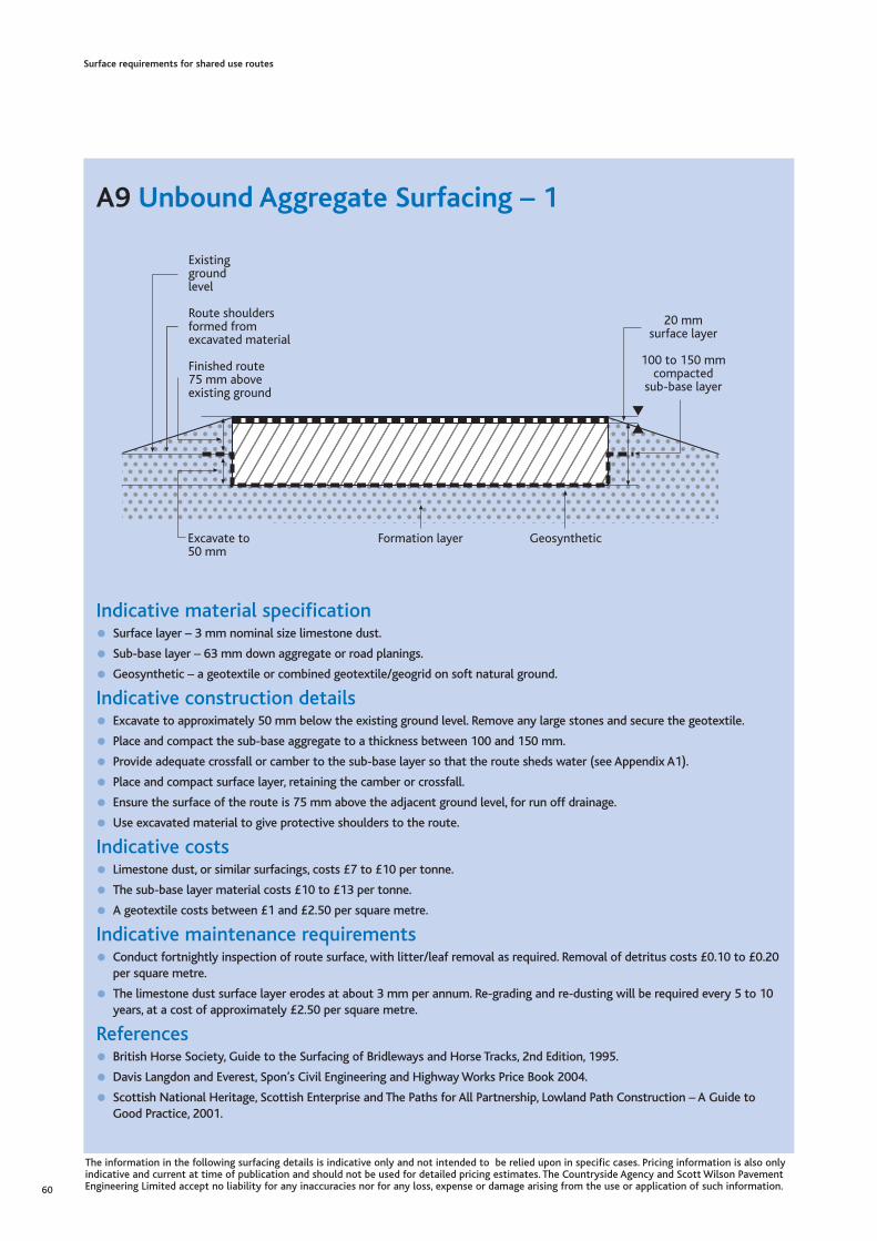
A9 Unbound Aggregate Surfacing – 1
Indicative material specification • Surface layer – 3 mm nominal size limestone dust.
• Sub-base layer – 63 mm down aggregate or road planings.
• Geosynthetic – a geotextile or combined geotextile/geogrid on soft natural ground.
Indicative construction details• Excavate to approximately 50 mm below the existing ground level. Remove any large stones and secure the geotextile.
• Place and compact the sub-base aggregate to a thickness between 100 and 150 mm.
• Provide adequate crossfall or camber to the sub-base layer so that the route sheds water (see Appendix A1).
• Place and compact surface layer, retaining the camber or crossfall.
• Ensure the surface of the route is 75 mm above the adjacent ground level, for run off drainage.
• Use excavated material to give protective shoulders to the route.
Indicative costs• Limestone dust, or similar surfacings, costs £7 to £10 per tonne.
• The sub-base layer material costs £10 to £13 per tonne.
• A geotextile costs between £1 and £2.50 per square metre.
Indicative maintenance requirements• Conduct fortnightly inspection of route surface, with litter/leaf removal as required. Removal of detritus costs £0.10 to £0.20
per square metre.
• The limestone dust surface layer erodes at about 3 mm per annum. Re-grading and re-dusting will be required every 5 to 10years, at a cost of approximately £2.50 per square metre.
References• British Horse Society, Guide to the Surfacing of Bridleways and Horse Tracks, 2nd Edition, 1995.
• Davis Langdon and Everest, Spon’s Civil Engineering and Highway Works Price Book 2004.
• Scottish National Heritage, Scottish Enterprise and The Paths for All Partnership, Lowland Path Construction – A Guide toGood Practice, 2001.
Surface requirements for shared use routes
60
Formation layer Geosynthetic
20 mmsurface layer
100 to 150 mmcompacted
sub-base layer
Existinggroundlevel
Route shouldersformed fromexcavated material
Finished route75 mm aboveexisting ground
Excavate to50 mm
The information in the following surfacing details is indicative only and not intended to be relied upon in specific cases. Pricing information is also onlyindicative and current at time of publication and should not be used for detailed pricing estimates. The Countryside Agency and Scott Wilson PavementEngineering Limited accept no liability for any inaccuracies nor for any loss, expense or damage arising from the use or application of such information.

A10 Unbound Aggregate Surfacing – 2
Indicative material specification• Hoggin – Clay and fines content should be the minimum sufficient to bind the material.
• Sub-base aggregate – 63 mm down.
• Optional surfacing layer – 10 to 5 mm rounded gravel.
• If required, a geotextile separator can be placed over the formation layer.
Indicative construction details• Excavate to approximately 175 mm, secure any geotextile required.
• Place and compact the sub-base and then the hoggin. Provide an appropriate camber or crossfall to the hoggin layer.
• Place the surfacing gravel, if used.
Indicative costs (supply, place and compact)• Hoggin may be won locally or imported to the site, at a cost of less than £2 per square metre for a 50 mm thick layer.
• The sub-base layer material costs between £10 and £13 per tonne.
• A geotextile separator, if used, costs £1 to £2.50 per square metre.
Indicative maintenance requirements• Inspect regularly, such as monthly or bimonthly, and rake surfacing as required. Remove litter and detritus from the surface,
at a cost of £0.10 to £0.20 per square metre.
• Re-grade and re-dress surface as necessary, typically once every 5 or 10 years, at a cost of approximately £2.50 per squaremetre.
References• British Horse Society, Guide to the Surfacing of Bridleways and Horse Tracks, 2nd Edition, 1995.
• Davis Langdon and Everest, Spon’s Civil Engineering and Highway Works Price Book 2004.
• Scottish National Heritage, Scottish Enterprise and The Paths for All Partnership, Lowland Path Construction – A Guide toGood Practice, 2001.
Surface requirements for shared use routes
61
Formationlayer
Optional gravelsurfacing layer
125 mmsub-base layer
50 mm hoggin layer
The information in the following surfacing details is indicative only and not intended to be relied upon in specific cases. Pricing information is also onlyindicative and current at time of publication and should not be used for detailed pricing estimates. The Countryside Agency and Scott Wilson PavementEngineering Limited accept no liability for any inaccuracies nor for any loss, expense or damage arising from the use or application of such information.

A11 Stone Pitch Surfacing
Indicative material specification• Locally sourced surface stone – stone can be obtained from
boulder fields or scree slopes only if these features are notof ecological or geological importance.
• Anchor Stones should be at least 600 mm deep and PitchingStones 300 mm.
Indicative construction details• Excavate to the required depth. The finished surfacing should be at or below the depth of the surrounding ground or
vegetation. The excavated depth should accommodate the stones but finish the path at or below this level.
• Do not excavate more than can be completed in one day. Two people can complete a 10 m long section of a 1 m wide routein one day.
• Start on the downhill end of a section and work up the hill.
• Dig in the Anchor Stone so that it is flush with the lower surface. The Anchor Stone should be dug in as deep as possible.
• Dig in the Pitching Stones, leaving the flattest surface upwards and at no more than 5 degrees from the horizontal. The risebetween stones should be not more than 200 mm.
• Butt adjoining stones against each other, wedging them in place using smaller stones in the gaps. Use larger stones at thepath edges to prevent lateral movement.
• Compact excavated soil into gaps and crevices. Fertilise and reseed when appropriate.
Indicative material costs• Pitching stones are usually available in the vicinity where these surfacings are required. Imported stones are likely to cost in
excess of £40 per square metre.
• Transportation of stone and machinery to site by helicopter to remote areas costs £550 to £600 per hour. Depending on thelength of the flight, a helicopter can usually transport 20 to 25 tonnes per hour, lifting a maximum weight of 1 tonne pertrip.
Indicative maintenance requirements• Regular inspection.
• Fertilising and reseeding of vegetation as necessary.
• Reinstatement of any loose stones when required.
References• Countryside Agency, Pennine Bridleway National Trail Specification, 1999.
• Davies, P., Loxham, J. and Huggon, G., Repairing Upland Path Erosion – A Best Practice Guide, Lake District National ParkAuthority, National Trust and English Nature, 1996.
• Davis Langdon and Everest, Spon’s Civil Engineering and Highway Works Price Book 2004.
Surface requirements for shared use routes
62
600 mm depthAnchor Stone
Gradient 1:4 (25%)
Pitching Stone
Gaps packed withsmall stones and
excavated soil
300 mmExcavation depth
Surroundingsurface
Seeding encouragesre-vegetation in joints
The information in the following surfacing details is indicative only and not intended to be relied upon in specific cases. Pricing information is also onlyindicative and current at time of publication and should not be used for detailed pricing estimates. The Countryside Agency and Scott Wilson PavementEngineering Limited accept no liability for any inaccuracies nor for any loss, expense or damage arising from the use or application of such information.

A12 Floating Path Construction
Indicative material specification• Geosynthetics – use either:
– A separator geotextile and a separate strengthening geogrid.
– A combined geotextile/geogrid.
– A woven strengthening geotextile.
• Alternatively brushwood or brushwood bundles may be used.
• Sub-base material – 75 mm down aggregate.
• Surfacing layer – 6 mm to dust aggregate.
Indicative construction details• Excavate to a suitable formation layer using an excavator with bogmaster tracks. Retain the excavated materials for verges.
• Place and secure geotextile separator and geogrid to the formation layer.
• When the groundwater is very close to the surface, it is appropriate to place the geotextile and geogrid directly onto thesurface and build the route on top of the existing ground level.
• Place the sub-base layer to a minimum thickness of 250 mm. The sub-base layer should not be compacted.
• If the natural ground is very weak, additional geogrid layers may be required within the sub-base layer.
• Provide a camber or crossfall to the sub-base layer (see Appendix A1).
• Place a minimum 20 mm thickness of surfacing material over the sub-base layer.
Indicative material costs• The geotextile separator is between £1 and £2.50 per square metre.
• Sub-base material costs between £10 and £13 per tonne.
• Surfacing material costs between £7 and £10 per tonne.
Indicative maintenance requirements• Regular inspection.
• Redressing of surfacing material can be expected every 5 to 10 years, at a cost of approximately £2.50 per square metre.
References• Davies, P., Loxham, J. and Huggon, G., Repairing Upland Path Erosion – A Best Practice Guide, Lake District National Park
Authority, National Trust and English Nature, 1996 .
• Davis Langdon and Everest, Spon’s Civil Engineering and Highway Works Price Book 2004.
Surface requirements for shared use routes
63
Surfacing layer
Level ofgroundwatertable
GeogridGeotextile
250 mmsub-base
The information in the following surfacing details is indicative only and not intended to be relied upon in specific cases. Pricing information is also onlyindicative and current at time of publication and should not be used for detailed pricing estimates. The Countryside Agency and Scott Wilson PavementEngineering Limited accept no liability for any inaccuracies nor for any loss, expense or damage arising from the use or application of such information.

A13 Sealed Bituminous Surface – 1 Asphalt Surface
Indicative material specification
• Sub-base layer – 63 mm down aggregate.
• Surfacing layer – 60 mm thickness of asphalt. Select either:
• 20 mm thickness of dense bituminous macadam containing 6 mm aggregate, over 40 mm thickness of dense bituminousmacadam containing 20 mm aggregate.
• 60 mm thickness of dense bituminous macadam containing 14 to 20 mm graded aggregate.
Indicative construction details
• Routes predominantly for cycling should be machine laid to provide adequate ride quality.
• Excavate to 150 mm below the existing ground level and proof roll the formation layer.
• Treat the formation layer with weed killer and, on weak natural ground, secure a geotextile/geogrid.
• Place and compact the sub-base layer using a vibro plate or roller, to achieve the required thickness.
• Lay the asphalt surface layer, with the required camber or crossfall (see Appendix A1).
• The finished surface should be raised above the existing ground level, with soft edges/verges reinstated from the excavatedmaterial.
Indicative material costs
• Sub-base material costs between £10 and £13 per tonne.
• Asphalt surfacing costs between £2 and £5 per square metre.
Indicative maintenance requirements
• Remove litter and detritus from the surface, at a cost of £0.10 to £0.20 per square metre.
References
• Davis Langdon and Everest, Spon’s Civil Engineering and Highway Works Price Book 2004.
• Sustrans, Making Ways for the Bicycle, 1994.
• Scottish National Heritage, Scottish Enterprise and The Paths for All Partnership, Lowland Path Construction – A Guide toGood Practice, 2001.
Surface requirements for shared use routes
64
2500 mm width surfacing layer
3000 mm width sub-base layers
Existingground level
Make up shoulders tomeet the route surface
60 mm thickness ofasphalt surface course
150 mmthickness of
sub-baseaggregate
The information in the following surfacing details is indicative only and not intended to be relied upon in specific cases. Pricing information is also onlyindicative and current at time of publication and should not be used for detailed pricing estimates. The Countryside Agency and Scott Wilson PavementEngineering Limited accept no liability for any inaccuracies nor for any loss, expense or damage arising from the use or application of such information.

A14 Sealed Bituminous Surface – 1 Surface Dressing
Material specification
• Sub-base - 63 mm down aggregate.
• Surface dressing aggregate - 6 mm to 10 mm chippings.
• Surface dressing binder - Bitumen emulsion, which may be reinforced with glass fibres.
• Edging (if required) - Tanalised timber, otherwise excavate formation for structural layer for re use on route surface edgings.
General construction details
• Insert timber edging into the natural ground at a level that provides suitable crossfall across the route. Alternatively, excavatethe ground to the required depth. Retain any material arising from excavation.
• Place and compact the sub-base material to the appropriate thickness, and provide crossfall/camber (see Appendix A1).
• Single surface dressing: Spray bitumen emulsion onto the sub-base at a rate of 2 litres per square metre. Spread thechippings over the bitumen and roll the chippings into the bitumen before it hardens. Brush off and reuse any loosechippings.
Indicative material costs
• The sub-base layer material costs between £10 and £13 per tonne.
• Single surface dressing costs approximately £0.50 per square metre.
Indicative maintenance requirements
• Regularly clear litter and leaf debris, at a cost of £0.10 to £0.20 per square metre.
• The surface will need to be re-dressed every 5 to 10 years, depending on wear, at a cost of approximately £0.50 per squaremetre.
References
• County Surveyors Society Countryside Working Group, Report on the Surfacing of Bridleways, 2005.
• Davis Langdon and Everest, Spon’s Civil Engineering and Highway Works Price Book 2004.
• Scottish National Heritage, Scottish Enterprise and The Paths for All Partnership, Lowland Path Construction – A Guide toGood Practice, 2001.
Surface requirements for shared use routes
65
Surface dressing layerTimberedging
Formation layer
100 mm thicknesssub-base
The information in the following surfacing details is indicative only and not intended to be relied upon in specific cases. Pricing information is also onlyindicative and current at time of publication and should not be used for detailed pricing estimates. The Countryside Agency and Scott Wilson PavementEngineering Limited accept no liability for any inaccuracies nor for any loss, expense or damage arising from the use or application of such information.

British WaterwaysWillow Grange, Church Road,Watford, Herts WD17 4QATel: 01923 201120 Fax: 01923 201400Email: [email protected] www.british-waterways.co.uk
British Horse SocietyStoneleigh Deer Park, Kenilworth,Warwickshire, CV8 2XZTel: 08701 202244 Fax: 01926 707800Email: [email protected]
British Trust for Conservation VolunteersConservation Centre, 163 Balby Road, Doncaster,South Yorkshire DN4 0RHTel: 01302 572 244 Fax: 01302 310 167Email: [email protected]
Byways and Bridleways TrustPO Box 117, Newcastle upon Tyne NE3 5YTwww.bbtrust.org.uk
Council for British ArchaeologySt Mary’s House, 66 Bootham,York YO30 7BZ Tel: 01904 671417 Fax: 01904 671384www.britarch.ac.uk
Country, Land and Business Association16 Belgrave Square, London SW1X 8PQTel: 020 7235 0511 Fax: 020 7235 4696Email: [email protected]
Countryside AgencyJohn Dower House, Crescent Place, Cheltenham,Gloucestershire GL50 3RATel: 01242 533222 Fax: 01242 584270Email: [email protected]
Countryside Recreation NetworkSheffield Hallam University, Unit 7, Sheffield Science Park,Howard Street, Sheffield S1 2LXTel: 0114 225 4494 Fax: 0114 225 4038Email: [email protected]
CTC (the National Cyclists’ Organisation)69 Meadrow, Godalming, Surrey GU7 3HS Tel: 0870 873 0060 Fax: 0870 873 0064Email: [email protected]
Department of Environment, Food and Rural Affairs (Defra)Sponsorship, Landscape & Recreation Division Zone 1/02, Temple Quay House, 2 The Square,Temple Quay, Bristol BS1 6EBTel: 0117 372 8204 Fax: 0117 372 8587E-mail: [email protected]/wildlife-countryside/issues/public/index.htm
Department of Transport (DfT)Great Minster House, 76 Marsham Street, London SW1P 4DRTel: 020 7944 8300 Fax: 020 7944 9622www.dft.gov.uk
Disabled Ramblers 14 Belmont Park Road, Maidenhead, Berkshire SL6 6HTTel: 01628 621414www.disabledramblers.co.uk
Disability Rights CommissionFREEPOST MID02164, Stratford upon Avon CV37 9BRTel: 08457 622 633Textphone: 08457 622 644 Fax: 08457 778 878www.drc.gov.uk
English HeritagePO Box 569, Swindon,Wiltshire SN2 2YPTel: 0870 333 1181 Fax: 01793 414926www.english-heritage.org.uk
English NatureNorthminster House, Peterborough PE1 1UATel: 01733 455101 Fax: 01733 455103Email: [email protected]
Environment AgencyNational Customer Contact CentrePO Box 544, Rotherham, South Yorks S60 1BYTel: 08708 506506 www.environment-agency.gov.uk
Fieldfare Trust7 Volunteer House, 69 Crossgate, Cupar, Fife KY15 5ASTel: 01334 657708 Fax: 0870 7066008Email: [email protected]
Forestry Commission EnglandGreat Eastern House, Tennison Road, Cambridge CB1 2DUTel: 01223 314546 Fax: 01223 460699Email: [email protected]/england
Surface requirements for shared use routes
66
Appendix B Useful Contacts and Sources of Further Information

Health and Safety Executive (Construction Division)Rose Court, 2 Southwark Bridge, London SE1 9HSTel: 020 7556 2100 Fax: 020 7556 2109www.hse.gov.uk/construction
Institute of Public Rights of Way Officers PO Box 78, Skipton, North Yorkshire BD23 4UPTel: 07000 782318 Fax: 07000 782319Email: [email protected]
International Mountain Bike Association (UK)Woodview, Coddington, Ledbury HR8 1JHEmail: [email protected]
Local Government AssociationLocal Government House, Smith Square, London SW1P 3HZTel: 020 7664 3131 Fax: 020 7664 3030Email: [email protected]
Moorland Association16 Castle Park, Lancaster LA1 1YG.Tel: 01524 846846 Fax: 01524 382247Email: [email protected]
Moors for the Future,The Information Centre, Buxton Road, Castleton, S33 8WPTel/Fax: 01433 621656E-mail: [email protected] www.moorsforthefuture.org.uk
National Association for Areas of Outstanding Natural BeautyThe Old Police Station, Cotswold Heritage Centre, Northleach,Gloucestershire GL54 3JHTel: 01451 862007 Fax: 01451 862001www.aonb.org.uk
National Farmers’ UnionAgriculture House, 164 Shaftesbury Avenue, London WC2H 8HLTel: 020 7331 7200 Fax: 020 7331 7313email: [email protected]
National TrustHeelis, Kemble Drive, Swindon,Wiltshire SN2 2NATel: 0870 242 6620 Fax: 0870 242 6622Email: [email protected]
Royal Society of Wildlife TrustsThe Kiln,Waterside, Mather Road, Newark, NottinghamshireNG24 1WTTel: 0870 036 7711 Fax: 0870 036 0101 Email: [email protected] www.wildlifetrusts.org
Ramblers’ Association2nd Floor Camelford House, 87-90 Albert Embankment,London SE1 7TWTel: 020 7339 8500 Fax: 020 7339 8501 Email: [email protected]
Sensory TrustWatering Lane Nursery, Pentewan, St. Austell,Cornwall PL26 6BEEmail: [email protected]
Sport England3rd Floor Victoria House, Bloomsbury Square,London WC1B 4SETel: 08458 508 508 Fax: 020 7383 5740Email: [email protected]
SustransNational Cycle Network, 2 Cathedral Square,College Green, Bristol, BS1 5DD.Tel: 0117 926 8893 Fax: 0117 929 4173Email: [email protected]
Waste and Resources Action Programme (WRAP)The Old Academy, 21 Horse Fair, Banbury, OX16 0AHTel: 0808 100 2040www.wrap.org.uk
Waterway Recovery GroupPO Box 114, Rickmansworth,WD3 1ZYTel: 01923 711114Email: [email protected]
Surface requirements for shared use routes
67

John Dower House, Crescent PlaceCheltenham, Gloucestershire, GL50 3RA
Telephone 01242 521381Fax 01242 584270www.countryside.gov.uk
CA 213
This document is printed on recycled papercomprising 75% recycled post consumer waste.
September 2005