concrete slab track test on the high tonnage loop at the ... · capability of slab track to provide...
TRANSCRIPT

AREMA Annual Conference & Exposition September 2005 Chicago, Illinois
Concrete Slab Track Test on the High Tonnage Loop
at the Transportation Technology Center
by
David N. Bilow, P.E., S.E. Director, Engineered Structures
Portland Cement Association 5420 Old Orchard Road
Skokie, IL 60077 Tel 847-972-9064 Fax 847-972-9065
and
Dinqing Li, PhD, P.E. Principal Engineer
Transportation Technology Center, Inc. 55500 DOT Road
P.O. Box 11130 Pueblo, CO 81001 Tel (719) 584-0740 Fax (719) 584-0770

ABSTRACT
This paper presents results of field testing of two slab track sections on the High Tonnage Loop (HTL)
at the Transportation Technology Center (TTC) in Pueblo, Colorado. The test at TTC is part of the
Cooperative Slab Track Research and Demonstration Program for Shared Freight and High
Speed Passenger Service initiated by the Portland Cement Association (PCA) in 2001. The
objective of the program is to advance concrete slab track technology and to demonstrate the
capability of slab track to provide a low maintenance and safe track structure for shared high-
speed rail and freight on U.S. railroads.
As part of the program, laboratory tests were performed on two types of slab track and the results
were presented at the July 2003 AREMA Conference by PCA. One type of slab track uses
direct fixation fasteners mounted to the top surface of a concrete slab and the second type uses
independent dual concrete block ties with rubber boots and pads embedded in the concrete slab.
In the summer of 2003, following successful completion of the laboratory tests, a 550 foot test
section of slab track was constructed at TTC on the HTL.
The slab track test at TTC is sponsored by the Federal Railroad Administration (FRA) and PCA.
The FAST train at TTC using 315,000-lb freight cars (39 ton axle loads) has accumulated over 100
million gross tons of traffic on the test section. Results show that slab track can accommodate the heavy
axle freight rail loads while maintaining the vertical and horizontal geometry required by high speed rail.
Key Words: concrete, freight railroad, high-speed trains, railroad track, shared corridor, slab
track, R & D, structural design, transitions, high axle load, Transportation Technology Center,
safe track, rail transit

INTRODUCTION
The expansion of high speed rail (HSR) corridors and the increasing use of heavy axle load
freight cars in the U.S. influenced the Portland Cement Association (PCA) in 2000 to study slab
track as an alternative to ballasted track. PCA also realized that in the U.S. for some corridors,
high speed rail passenger trains would most likely share track with freight trains because of the
high cost of track construction and maintenance. The challenge is to design and construct a track
system that provides the required track geometry for future high-speed passenger trains traveling
up to 200 mph and the strength to withstand repeated heavy axle loads from freight trains. It was
also understood that ballast is the main source of average and differential settlement in most
track as stated in Track Geotechnology and Substructure Management by Ernest T. Selig and
John M. Waters. To address this challenge, PCA created the Cooperative Concrete Slab Track
Research and Demonstration Program for Shared Freight and High Speed Passenger Service.
The objective of the program is to advance concrete slab track technology and to demonstrate the
capability of slab track to provide a low maintenance and safe track structure for shared high
speed rail and heavy freight on U.S. railroads.
PCA initiated work on the program in 1999 and prepared the paper Concrete Slab Track for
Freight and High Speed Service Applications, a Survey of Practice which was published in
Transportation Research Record in 2001 by TRB. PCA also organized a panel of experts to
advise PCA on the slab track program and initiated full scale laboratory tests on two types of
slab track: direct fixation slab track (DFST) and independent dual block slab track (IDBT).
After completion of the successful laboratory tests, construction started in 2003 on a 550 foot
long slab track test section at the Transportation Technology Center (TTC) in Pueblo, Colorado.
The objectives of the work at TTC are to build and test a prototype section of slab track in order

to validate the design procedure developed by CTLGroup for PCA, validate the laboratory tests,
and to demonstrate slab track’s durability for heavy, high traffic loads while maintaining the
track geometry required by HSR at low maintenance cost. The two year test on the High
Tonnage Loop (HTL) of the Facility for Accelerated Service Testing (FAST) at TTC has
subjected the slab track to more than 100 million gross tons (mgt) of heavy axle (39 ton) load
freight traffic as of June 2005. The Federal Railroad Administration (FRA) and PCA sponsor the
field test which will be extended until September 2006 to accumulate an additional 50 mgt. This
paper describes the slab track test section, measurement procedures, and summarizes the results
of the test to date.
TEST ENVIRONMENT
TTC, the largest railroad test facility in the world, is owned by FRA and is operated by the
Transportation Technology Center, Inc. (TTCI), a subsidiary of the Association of American
Railroads. The facility is located on semi arid land 21 miles east of Pueblo, Colorado. The
record summer high temperature is 108 degrees and record winter low temperature is -30 degrees
(F). The slab track test section was constructed on the HTL. The HTL is 2.7 miles long and is
used for track component reliability, wear, and fatigue research under heavy axle (39 ton) loads.
The test train generally has four locomotives and about 70 cars each weighing 315,000 pounds.
The HTL is divided into test sections which generally correspond to tangents, spirals, curves and
turnouts. The slab track test section is located in the bypass track on section 38 as shown in
Figure 1. Section 38 is a five degree curve with a 4” superelevation and was selected to
demonstrate slab track performance under severe curvature conditions. The test train operation
generally accumulates 1.0 mgt a day at a nominal speed of 40 miles per hour. Specialized test
consists such as the track loading vehicle (TLV) and track geometry measurement system
(TGMS) can apply specific loads to the track and perform various measurements.
SLAB TRACK TEST SECTION
The slab track test section consists of 250 feet of DFST, 250 feet of IDBT, and two pieces of
transition track each 25 feet long between each end of the slab track and the adjacent ballasted
track. The slab track was constructed to tolerances equal to the more stringent of FRA Class 9
Track Safety Standards and Amtrak’s construction tolerance for HSR as shown in Table 1.
These two types of cast-in-place (CIP) slab track were selected because several versions of the
DFST are in service on passenger and freight track in North America and the IDBT is in service
on the heavily traveled Eurotunnel beneath the English Channel. However, the existing slab
track installations are not subject to 39 ton axle loads or high speed traffic.
The DFST is a 12 inch thick concrete slab 10’-6” wide with 5,000 psi concrete and two mats of
steel reinforcement as shown in Figure 2. The DFST uses the Acoustic Loadmaster DF track
fastener manufactured by Advanced Track Products, Inc., made of ductile iron and natural rubber
and spaced at two foot intervals. The fastener is anchored to the slab by four anchor bolts.
The IDBT, also called Low Vibration Track (LVT), consists of a 7.75 inch thick CIP bottom slab
10’-6” wide with 5,000 psi concrete and two mats of steel reinforcement as shown in Figure 3.
The LVT system is supplied by The Permanent Way Corporation and the STL rail fastenings
used on the LVT blocks are provided by Sonneville International Corporation. The precast
concrete block ties fitted with rubber boots are set in place above the bottom slab and self
compacting concrete is poured around the block ties to a depth of 7.25 inches and allowed to
cure. Under each block tie and inside the boot is an elastomeric pad.

During construction of the IDBT and DFST, a six inch layer of soil cement was first constructed
to minimize settlement of the subgrade and to provide a working platform for concrete slab
construction.
The 25 ft long transition zone between the slab track and the ballasted track consists of a 12 inch
thick reinforced concrete slab with upturned walls, ballast, and concrete ties as shown in Figure
4. There is approximately 16 inches of ballast between the bottom of the ties and top of the
concrete slab. The purpose of the transition zone is to accommodate the difference in track
modulus between the concrete slab track and the adjacent ballasted track.
MEASUREMENTS & RESULTS
The objectives of the slab track measurements are to characterize the slab track, quantify slab
track response, quantify the load transfer between the rails and the subgrade, and to quantify slab
track performance.
Slab Track Characterization
Slab track is characterized by track geometry, track modulus, and gage strength. Measurements
made by TTCI’s Track Geometry Measurement System (TGMS) as shown in Figure 5 indicated
that the slab track as constructed was within Class 9 tolerances except for one spot at the end of
the DFST slab track adjacent to the transition zone where the alignment was ¾ inch out of
tolerance. The slab track alignment was easily corrected before proceeding with the HAL train
runs.
TTCI’s TLV is used to measure the track modulus and gage strength. As shown in Figure 6
between tie 3 and tie 130, the DFST track modulus varies slightly but averages 2,100 psi. Also,

shown in Figure 6 between tie 130 and tie 253, the IDBT track modulus also varies slightly but
averages about 3,000 psi. The DFST and IDBT track modulus is similar to the track modulus of
ballasted track but can be modified by changing the properties of the elastomeric pads. The large
spike to a maximum of 7,000 psi on each end of the plot is for the transition zones which came
out much stiffer than anticipated. During train operation, no unusual dynamic behavior was
noted so it was decided not to soften the transitions but to leave the transitions as constructed.
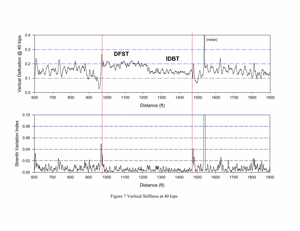
Figure 7 shows the vertical deflection of the track under the 40 kip vertical load from the TLV.
Under this load the DFST had a maximum vertical deflection of 0.22 inch and the IDBT had a
maximum vertical deflection of 0.17 inch, which are consistent with track modulus test results
for the two slab test sections.
The TLV measurement of gage strength is shown in Figure 8. The maximum gage measured in
the loaded condition is 57 inches for both the DFST and IDBT. The maximum gage measured in
the unloaded condition is 56.75 and 56.85 for the DFST and IDBT respectively.
Slab Track Response
The slab track rail to slab deflection measured by the wayside instrumentation is shown in Figure
9. The maximum vertical deflection in the DFST rail is .25” and in the IDBT rail is .15”. The
maximum lateral deflection of the DFST rail is 0.10” and of the IDBT rail is 0.06”. The vertical
force measured by the wayside instrumentation is shown in Figure 10 for the DFST and in Figure
11 for the IDBT. The maximum vertical force on the rail is 50 kips and the maximum lateral
force on the rail is 13 kips.
Load Transfer from Rails to Subgrade

Measurements of the load in the fasteners were not made during the test at TTC. Therefore, we
refer to the laboratory test where it was determined that for the DFST, approximately 24% of the
wheel load goes to the fastener under the wheel while for the IDBT 41% of the wheel load goes
to the fastener under the wheel.
The peak pressures in the soil under a transverse section at the crib location of the IDBT at TTC
varied from 9 psi to 12 psi. Under the IDBT fastener locations the soil pressure varied from 8 psi
to 11 psi. Under the DFST at the crib location the soil pressure varied from 8 psi to 9 psi and at
the fastener location the soil pressure appeared to be constant at 11 psi. The results of the soil
pressure measurements show that the pressures under slab track are quite uniform.
During the TTCI test, accelerometers were placed on the rail and slab to measure the attenuation
of vibration from rail to slab. For a dynamic force with an acceleration of slightly less than 20
times the acceleration of gravity (20g), the measured acceleration on the concrete slab was
slightly less than 1.5 g for an attenuation of 1/13 the force on the rail.
Reinforcement bars were strain gauged and the strains measured while the train traveled over the
test section. The maximum tensile strain (100 microstrain) was measured in the bottom
longitudinal bars in the DFST and this translates to a stress of 2,900 psi, substantially less than
the allowed stress of 24,000 psi.
Slab Track Performance
The multi-depth deflectometers at the level of the concrete slab indicate an elastic deflection
maximum of from 0.04 in. to 0.06 in. under the train load. This maximum elastic deflection due
to the subgrade did not change from the train operation at 2 mgt to the train operation at 65 mgt,

indicating that there was no change in the subgrade stiffness over this period. The measured
maximum vertical wheel load on the rail was 50 kips and the maximum lateral load was 13 kips
on each type of slab track. The maximum vertical and lateral loads on the slab track are
substantially less than the maximum vertical and lateral loads measured earlier on ballasted
track in the test section 38. This difference between slab track and ballasted illustrates the
attenuation of dynamic wheel forces by the slab track fasteners.
COMPARISON OF RESULTS WITH LABORATORY TESTS AND ANALYSIS
To advance slab track technology by improving analysis and test methods, comparisons are
made between the TTCI test results, laboratory test results, and the analysis made during the
design of the slab track test section. The wheel loads used during the laboratory test and during
the structural design of the test section at TTC, were derived from earlier measurements of
ballasted track in Section 38 of the HTL at TTC. The maximum vertical wheel load from the
ballasted track measurements was 68 kips while the maximum load measured on the slab track
test section at TTC was 50 kips, a difference of 36%. The maximum lateral wheel load from the
earlier ballasted track measurements was 22 kips while the maximum lateral load measured on
the slab track test section at TTC was 13 kips for the IDBT and the DFST. The rail to slab
deflection in the laboratory slab track test was about equal to the TTC test section for the IDBT
and greater than the TTC test section for the DFST. The rail to slab deflection in the structural
analysis was about 10% higher than in the TTC test section for the IDBT and 40% less than the
TTC test section for the DFST. However, it should be noted that the deflections themselves are
small, less than 0.25 in.
The maximum slab deflection ranged from .04 in to .06 in at TTC, .065 in for the structural
analysis, and from .021 in to .024 in the laboratory. This indicates that the rubber mat used to

simulate the subgrade in the laboratory was slightly too stiff to simulate the TTC subgrade
behavior accurately, but the structural analysis was fairly accurate.
Conclusion
Several conclusions can be reached regarding the test on the concrete slab track section at TTC
as follows:
1. Concrete slab track can be constructed to high-speed rail tolerances (Class 9) using
conventional slab track construction methods.
2. The impact forces from the FAST train are significantly attenuated by the elastic
properties of the fasteners and block ties and are therefore lower than on ballasted track.
3. Slab track can maintain high-speed track geometry while being subjected to heavy axle
loads.
4. Soil pressures are evenly distributed under slab track.
5. Modern methods of structural analysis can be used to design slab track
6. The track modulus of slab track is much more uniform than for ballasted track.
Acknowledgements
The research reported in this paper was conducted by the Transportation Technology Center, Inc.
with the sponsorship of the Portland Cement Association and the Federal Railroad
Administration.
The authors thank Donald Plotkin of the FRA, Robert McCown, formerly of the FRA, and
Andrw Sluz of the Volpe Center for their advice and encouragement during the test program.
The authors also acknowledge contributions to the Cooperative Concrete Slab Track Research

and Demonstration Program from expert panel members, fastener suppliers, Transportation
Technology Center, Inc. personnel, and other PCA and CTL personnel as follows: Steven
Chrismer, Nathan J. Higgins, Richard S. Lanyi, Mohammad Longi, Nicholas J. Skoutelas, Jan H.
Zicha, Bernard Sonneville, William Osler, Kenneth J. Laine, Shiraz D. Tayabji, Claire G. Ball,
William P. Kucera, and Gene M. Randich.
The contents of this paper reflect the views of the authors, who are responsible for the facts and
accuracy of the data presented. The contents do not necessarily reflect the views of the Portland
Cement Association.
References
1. Selig, E.T. and Waters, J.M. “Track Geotechnology and Substructure Management”
Thomas Telford Publications, 1994
2. Tayabji, S. D. and Bilow, D. N. “Concrete Slab Track for Freight and High Speed
Service Applications, A Survey of Practice”, TRB Paper Number 01-0240, 2001.
3. Ball, C.B. “Slab Track Laboratory Test Program”, PCA R & D Serial No. 2795, 2004
4. Lotfi, H.R. and Oesterle, R.G., “Slab Track for 39-Ton Axle Loads, Structural Design”
PCA R & D Serial No. 2832
5. Lotfi, H.R. and Oesterle, R.G., “Analysis and Design of DFST and IDBT Slab Track
Laboratory Specimens” PCA R & D Serial No. xxxx (not published as of this date)

Tolerance FRA Safety Standards Amtrak Construction
Gage -1/4 to + 3/4 -3/32 to +1/16
Surface 62’ MCO ½” 1/8”
Alignment 62’ MCO 3/8” 1/8”
Table 1 High-speed Rail Construction Tolerances

Figure 1 Slab Track on the HTL and FAST Train
Sec. 38 - Slab track section
Figure 1a High Tonnage Loop Track Diagram

Figure 2 Direct Fixation Track (DFST)

Figure 3 Independent Dual Block Track (IDBT)

Figure 4 Transition Zone Under Construction
Distance (ft)1900 2000 2100 2200 2300 2400 2500 2600 2700 2800 2900 3000 3100 3200
Alig
nmen
t Rig
ht (i
n.)
-1.0
-0.5
0.0
0.5
1.0
1900 2000 2100 2200 2300 2400 2500 2600 2700 2800 2900 3000 3100 3200
Alig
nmen
t Lef
t (in
.)
-1.0
-0.5
0.0
0.5
1.0
25 mph30 mph35 mph40 mph
IDBT DFST
Figure 5 Initial Track Geometry

Tie #
-40 -20 0 20 40 60 80 100 120 140 160 180 200 220 240 260 280 300 320
Trac
k M
odul
us (i
n.)
0
2000
4000
6000
8000
3rd tie (DFST) Tie 253 (IDBT)
Tie 130 (center)
Figure 6 Measured Track Modulus Figure 6 Measured Track Modulus
Distance (ft)
600 700 800 900 1000 1100 1200 1300 1400 1500 1600 1700 1800 1900
Vertc
al D
eflc
etio
n @
40
kips
0.0
0.1
0.2
0.3
0.4
Distance (ft)
600 700 800 900 1000 1100 1200 1300 1400 1500 1600 1700 1800 1900
Stre
nth
Varia
tion
Inde
x
0.00
0.02
0.04
0.06
0.08
0.10
DFSTIDBT
(noise)
Figure 7 Vertical Stiffness at 40 kips

TLV Gauge Strength, CCW Direction, Dec. 8, 2003 (run#2)
Distance (ft)
300 400 500 600 700 800 900 1000 1100 1200 1300 1400 1500 1600
Cur
ve In
dica
tion
1
2
3
4
5
6
Distance (ft)
300 400 500 600 700 800 900 1000 1100 1200 1300 1400 1500 1600
Unl
oade
d &
Load
ed G
age
(in.)
56.0
56.5
57.0
57.5
58.0
Unloaded
Loaded
DFST IDBT
Figure 8 TLV Measured Gage Strength

Figure 9a Rail to Slab Deflection IDBT - Vertical, (Blue) & Lateral (Red) Inside Rail (Top) and Outside Rail (Bottom)
Figure 9b Rail to Slab Deflection DFST- Vertical, (Blue) & Lateral (Red) Inside Rail (Top) and Outside Rail (Bottom)

Figure 10a Wayside Lateral (Red) & Vertical (Blue) Rail Forces DFST Inside Rail (Top) and Outside Rail (Bottom)

Figure 10b Wayside Lateral (Red) & Vertical (Blue)Rail Forces IDBT Inside Rail (Top) and Outside Rail (Bottom)

List of Tables and Figures
Tables
Table 1 High-Speed Rail Construction Tolerances
Figures
Figure 1 Slab Track on the HTL and FAST Train
Figure 1a High Tonnage Loop Track Diagram
Figure 2 Direct Fixation Track (DFST)
Figure 3 Independent Dual Block Track (IDBT)
Figure 4 Transition Zone Under Construction
Figure 5 Initial Track Geometry
Figure 6 Measured Track Modulus
Figure 7 Vertical Stiffness at 40 kips
Figure 8 TLV Measured Gage Strength
Figure 9a Rail to Slab Deflection IDBT - Vertical, (Blue) & Lateral (Red)
Figure 9a Rail to Slab Deflection IDBT - Vertical, (Blue) & Lateral (Red)
Figure 9b Rail to Slab Deflection DFST- Vertical, (Blue) & Lateral (Red)
Figure 10a Wayside Lateral (Red) & Vertical (Blue) Rail Forces DFST
Figure 10b Wayside Lateral (Red) & Vertical (Blue)Rail Forces IDBT