on the mechanical compliance of technical systems
TRANSCRIPT

15
On the Mechanical Compliance of Technical Systems
Lena Zentner and Valter Böhm Ilmenau University of Technology,
Germany
1. Introduction
In the safe physical human-machine interaction the compliance of technical systems is an
elementary requirement (Zinn et al., 2004; Bicchi & Tonietti, 2004). The physical compliance
of technical systems can be provided either by control functions implementation and/or
intrinsic by structural configuration and material properties optimization (Beder &
Suzumori, 1996; Wang et al., 1998). The latter is advantageous because of higher reliability
as well as general simplicity of the design and production technologies (Beder & Suzumori,
1996; Ham et al., 2009). In the following we focus on mechanical systems with intrinsic
mechanical compliance.
In general the deformability of structures is primarly characterised by their stiffness.
Stiffness is the measure of the ability of a structure to resist deformation due to the action of
external forces (IFToMM Terminology, 2010). Compliant mechanisms are mechanisms,
whose functionality is based on its deformability. The mobility of these mechanisms results
from their mostly elastic or plastic deformability (The definition is based on (Bögelsack,
1995; Howell, 2001; Christen & Pfefferkorn, 1998)). For the description of these mechanisms
it is advisable to use the compliance instead of the stiffness. The compliance is the reciprocal
of stiffness and is defined as the measure of the ability of a structure to exhibit a
deformation due to the action of external forces (IFToMM Terminology, 2010). The goal of
each engineer is by the design of mechanisms the setting of compliance depending upon the
purpose of its application. It should be considered, that the compliance is dependent on a
variety of parameters. The optimal design of these mechanisms can be realized only with
precise knowledge of the influence parameters and possible types of compliance.
2. Influence factors of compliance
First, the factors will be considered that determine the compliance of mechanisms generally,
without a specific application.
The compliance of a mechanism is determined with respect to a displacement of a specific selected reference point or area of the mechanism as a result of an external force. That approach is necessary because the deformation of a mechanism is usually associated with varying displacements for differing areas of a mechanism. Accordingly, the compliance of a
www.intechopen.com

Mechanical Engineering
342
mechanism depends on the location of the reference point. At the same mechanism for the same load and boundary conditions, the evaluation of compliance with respect to different points leads to different results. For the reference usually the force application point or area is chosen. Depending on the application, the amount of the displacement vector of the reference point or its components are used when specifying the compliance.
The compliance is not a pure structure-related property, defined only by the initial geometric configuration and initial material properties. Geometric boundary conditions (location, type), the loading situation (location, type, magnitude, direction and loading history) and environmental conditions (e.g. thermal, chemical) must be also considered in order to formulate the compliance of a mechanism. On the material side the compliance is influenced by actual and previous environmental conditions and by the loading history (elastic or plastic behaviour). The geometric configuration for a given load is dependent on the material properties and geometric boundary conditions. Therefore the compliance of the mechanism depends on its actual geometric configuration and actual material properties and is valid only for the considered reference point by the given actual load and boundary conditions (Figure 1).
In practical applications, the boundary conditions, load levels and the reference point are given. In this case, the adjustment of the compliance can be achieved by appropriate design and material selection. The effort for the design depends on the variety of possible future applications of the mechanism.
Fig. 1. Influence factors on the mechanical compliance of mechanisms
2.1 Variability of compliance
Generally, the compliance can be either constant or variable. The constant compliance is impossible in the nature. However, we can use the theoretical models with constant compliance, for example, in the linear theory of small bending of beams. In this case the force is linear proportional to the displacement. Table 1 shows deferent compliance for a compliant quarter-circle shaped beam with radius R=20 mm. For this problem we use the Castigliano’s theorem for describing the displacement of the end of beam with the geometric linear theory:
3 2
2 2
1 2
3
12 4
FRu u u
EI
(1)
www.intechopen.com

On the Mechanical Compliance of Technical Systems
343
The compliance applied of the end of beam can be given by:
3 2
3
4
4
u R
F EI
(2)
The compliance would be demonstrated by means of one point for constant bending
stiffness in one dimension domain. Consequently, the constant compliance is the compliance
of the zero degree.
The mathematical model for the large displacements is based on the theory of curved
beams. The following equations are nonlinear equations of equilibrium and constitutive
equations of a curved beam (Zentner, 2003).
1 2
2 1
3 2
1
2
0
0
0
1
1cos
sin
Q Q
Q Q
EI Q
R
u
u
(3)
Where - curvature of the loaded beam, Qi – internal forces, EI3 - bending stiffness, ui –
displacements on the directions of x1 and x2, - angle between the tangent and the axis x1.
All these parameters depend on the beam coordinate s (0sL). This system of nonlinear
equations was solved with the program MATHEMATICA with boundary conditions:
1
2
1
2
0
0
0 0
0 0
0 0
( )
( )
( )
( )
( )
( )
Q L
Q L F
L
u
u
(4)
As for the large displacements, we have different compliances depending on the particular
position. To each position, a different force dF corresponds, which displaces a beam point
on du. This situation is presented in Table 1 as a curve in 2D domain. The different
compliance is characterized by ∂u/∂F dependent on u. By means of changing the
prestressing of a compliant structure its compliance can be changed. Another example of
this is a structure in the ring shape as a prestressed spring. While changing the clamping
with the help of the parameter h, the compliance of the spring can be purposefully set onto
the point P. Such compliance can be called the compliance of the first degree.
In addition to this, if we also take the temperature into consideration concerning a mechanism made of a temperature sensitive material, the compliance will depend on the
www.intechopen.com

Mechanical Engineering
344
two parameters, namely the displacement position and the temperature. In such a case we have compliance of the second degree. The surface F=F(u, T) would reflect the compliance depending on the two parameters, as a value for compliance ∂u/∂F for a definite temperature T and a particular displacement u.
The list of such parameters, which influence the compliance, can continue to be developed.
If the compliance depends on the N parameter, we deal with the case of the compliance of
the N degree.
Degree of compliance
Modelling Figure Compliance
N=0 Linear theory 3 2
3
4
4
u R
F EI
N=1 Non-linear theory (large deformations)
N=2
Non-linear theory and dependence of the temperature, e.g. E(T)
Table 1. Compliance of three degrees, from zero till two, for a compliant quarter-circle shaped beam (EI3=100 Nmm2, F=1N)
2.2 Distribution of compliance
The mostly deformable parts of a compliant mechanism are called as compliant joints. Compliant joints can be classified by their distribution of their compliance. The joints with concentrated, local compliance have a small deformable area with the reference to the dimension of a mechanism. In contrast, compliance joints with distributed compliance include a large area of the deformable part. The decision whether a deformable area is small or large, depends on the purpose of the modelling. For example, the installation of a substitute rigid body model for a compliant mechanism, a great role is played by extension of the joint.
www.intechopen.com

On the Mechanical Compliance of Technical Systems
345
In case of a joint with a local compliance, the rigid body joint is introduced in the most cases into the middle of the compliant part. With a compliant joint possessing the distributed compliance, it is important that the position of the rigid body joint is determined for a substitute model. It can be admitted that for the compliant joints the following conditions are available: if the extension of the joint is 10 or more times smaller than the biggest dimension of the whole mechanism, it is classified as a joint with a distributed compliance.
Mechanisms with concentrated compliance behave like classic rigid link mechanisms, where kinematic joints are replaced with flexible hinges, and in consequence methods conceived to design rigid body mechanisms can be modified and applied successfully in this case (Albanesi et al., 2010). Mechanisms with distributed compliance are treated as a continuum flexible mechanism, and Continuum Mechanics design methods are used instead of rigid body kinematics (Albanesi et al., 2010). An overview of calculation methods of compliant mechanisms is indicated in (Albanesi et al., 2010; Shuib et al., 2007).
3. Classification of compliant mechanisms concerning the deformation
In case the deformation-behaviour is chosen as a criterion for classifying compliant mechanisms, two subgroups – dynamic and static deformation – can be distinguished (Zentner & Böhm, 2009). Furthermore the static deformation behaviour of compliant mechanisms having a fixed compliance are considered, whereat influences caused by inertia are neglected. The static deformation behaviour is divided into stable and instable behaviour (Figure 2). Stable deformation behaviour is characterised by a surjective mapping of a particular load F on the deformation u. Thereby one can differentiate between a monotonic behaviour and the behaviour with a singular smooth reversion. In case of instable behaviour of compliant mechanisms snap-through (deformation-behaviour with jump-discontinuities) and bifurcation (local bifurcation of the behaviour) are possible.
Fig. 2. Classification of the static deformation of compliant mechanisms.
3.1 Stable deformation-behaviour of compliant mechanisms: monotonic deformation
Figure 3 shows an example of the monotonic deformation behaviour of a pneumatically driven compliant mechanism. By increasing the load (here: internal pressure) the characteristic deformation parameters such as the angle between the longitudinal-axis of the rigid structural parts also increases. This mechanism is used as a finger of a gripper.
www.intechopen.com

Mechanical Engineering
346
Fig. 3. Monotonic deformation behaviour of a pneumatically driven compliant mechanism made of silicone rubber
Another example concerns a compliant fluid driven structure, which is applied as a medical probe. The cross-section diameter of probe changes from at the fixed end (3 mm) to the free end (1 mm) linearly. In the probe model there is a hollow with constant diameter of 0.2 mm. An unstretchable thin fibre is embedded in the wall with constant distance h from the symmetry axes of probe-beam. Under inner pressure p in the hollow, with the cross-section of A, the probe structure will bend towards the embedded fibre. Linear material law is supposed. The equation for displacement of probe is calculated analytically in order to examine the possibilities to obtain the required bending.
1 2
2 1
3 2
1
2
0
0
0
1cos
sin
Q Q
Q Q pA
EI Q
u
u
(5)
Corresponding boundary conditions are:
1
2
3
1
2
0
0 0
0 0
0 0
( ) ( )
( )
( )( )
( )
( )
( )
Q L pA L
Q L
pA L hL
EI
u
u
(6)
0.005 0.01 0.015 0.02 0.025 0.03 x1 0.002
0.004
0.006
0.008
0.01
x2
5 4 23
1
fibre
h
A
Fig. 4. Displacement behaviour of a compliant fluid driven structure by increasing internal pressure (1-5)
www.intechopen.com
On the Mechanical Compliance of Technical Systems
347
The characteristic parameter for such structure is the angle between the tangent of beam-end and the x1-axe. This angle is strictly monotonic increasing, when the pressure rises.
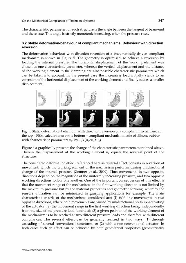
3.2 Stable deformation-behaviour of compliant mechanisms: Behaviour with direction reversion
The deformation behaviour with direction reversion of a pneumatically driven compliant mechanism is shown in Figure 5. The geometry is optimised, to achieve a reversion by loading the internal pressure. The horizontal displacement of the working element was chosen as one characteristic parameter, whereat the vertical displacement and the distance of the working element to the clamping are also possible characteristic parameters which can be taken into account. In the present case the increasing load initially yields to an extension of the horizontal displacement of the working element and finally causes a smaller displacement.
Fig. 5. Static deformation behaviour with direction reversion of a compliant mechanism: at the top – FEM-calculations; at the bottom – compliant mechanism made of silicone rubber with characteristic parameters ui, i=1,..,3 (u2>u3>u1)
Figure 6 a graphically presents the change of the characteristic parameters mentioned above. Therein the displacement of the working element u3 equals the reversal point of the structure.
The considered deformation effect, referenced here as reversal effect, consists in reversion of movement, which the working element of the mechanism performs during unidirectional change of the internal pressure (Zentner et al., 2009). Thus movements in two opposite directions depend on the magnitude of the uniformly increasing pressure, and two opposite working directions follow one another. One of the important consequences of this effect is that the movement range of the mechanisms in the first working direction is not limited by the maximum pressure but by the material properties and geometric forming, whereby the sensors utilization can be minimized in grasping applications for example. The main characteristic criteria of the mechanisms considered are: (1) fulfilling movements in two opposite directions, where both movements are caused by unidirectional pressure-activating of the actuator; (2) the movement range in the first working direction being, independently from the size of the pressure load, bounded; (3) a given position of the working element of the mechanism is to be reached at two different pressure loads and therefore with different compliances. The reversal effect can be generally realized in two ways: (1) through cascading of several conventional structures; or (2) with a non-conventional actuator. In both cases such an effect can be achieved by both geometrical properties (geometrically
www.intechopen.com

Mechanical Engineering
348
asymmetrical actuators), and material properties (actuators with variation of the material properties). A combination of materials of different elasticity and/or anisotropic materials can fulfil this characteristic, too. The numerical calculations approved, that the mechanism behaviour is influenceable geometrically and materially. Hence it can be adjusted to specific tasks.
Compared to other mechanisms, more complex motion trajectories can be easily provided with unidirectional pressure change with the help of these mechanisms.
One application for a mechanism having the property of a direction reversion is using it as gripping fingers. Through model based optimisation a novel dependency of the load on the displacement could be achieved (Figure 6 a, broken line). Therein the characteristic displacement will not increase at a defined value of load irrespective of further increase of load. This property puts aside the sensory effort to monitor the gripping force. This force is already defined by the structure’s mechanical properties. Such a structure is shown in Figure 6 b.
Fig. 6. a: I – Dependency of displacement u on internal pressure p of the mechanism introduced in Figure 4, II – p(u) for gripping-fingers with defined gripping-force; b: gripping-fingers with defined gripping-force made of silicone rubber
3.3 Instable deformation behaviour of compliant mechanisms: Snap-through
In contrast to the stable deformation behaviour of compliant mechanisms, the instable case has more than one equilibrium position for a particular load. The instable deformation behaviour shows snap-through or bifurcation.
In case of snap-though a sudden transition from one equilibrium position to another happens. Thereby a given load corresponds to several equilibrium positions. In Figure 7, a rotational structure is shown having a half-toric curve around the spherical curve in the origin state. One characteristic feature of such a mechanism is the potential bistable deformation behaviour, which can be enforced by the specified geometric parameters (shape, wall thickness, etc.).
Fig. 7. Snap-through of a curved mechanism having a monostable deformation behaviour
www.intechopen.com

On the Mechanical Compliance of Technical Systems
349
Fig. 8. Snap-through of a curved mechanism having a bistable deformation behaviour
Two different mechanisms with a big and small wall thickness are presented in Figure 7 and 8, respectively. By increasing the load, the angular point (centre point) of the median curvature of both mechanisms moves outwards up to the critical load (Figure 9 c). Herein the value of the critical load is different to the named structures. An arbitrary small rise of load causes a huge displacement, as soon as the critical load is reached. In this process the median curvature penetrates completely (state 2 in Figure 9). Removing the load causes the first mechanism to reverse to the original position (monostable deformation). This is demonstrated by state 3 in Figure 9 a. The second mechanism switches to another equilibrium position (bistable deformation), named in Figure 9 b with state 3. A sketch of both characteristics and the calculated positions by means of FEM is shown in Figure 9 c.
Fig. 9. Sketch of Snap-through behaviour of a curved mechanism: mechanism with monostable deformation (l.), mechanism with bistable deformation (r.)
Fig. 10. Applications as mechanical valves demonstrated for double-curved rotational mechanisms: a, b – pipe with one output is disabled for p=pcr, c – pipe with two outputs A and B, output B is closed if critical load is reached
Some applications of these mechanisms used as mechanical valves are shown in Figure 10. To generate bistable deformation (Figure 10 a) an opening is inserted in the centre point of
www.intechopen.com

Mechanical Engineering
350
the mechanism. Because of the critical dynamical pressure the mechanism is deformed and the flow is interrupted. In this case the current position guarantees the closure of the pipe. Low-pressure on the compliant part of the valve makes the flow possible again. The next Figure 10 b shows that the effect of the critical pressure yields to a deformation of the monostable mechanism, so the pipe is completely closed. If the pressure falls under the critical level, the original position is recaptured and the flow rate is reconstituted. The last example in Figure 10 c illustrates a valve installed in a pipe with two outputs. Output B is disabled, as soon as the critical pressure is reached. Decreasing the pressure enables this output.
3.4 Instable deformation behaviour of compliant mechanisms: Bifurcation
Situations with bifurcation of structures are avoided systematically in engineering. The following theoretical analyses reveal some opportunities to apply this behaviour profitably to a technical system.
The best known examples for the loss of stability under static loads are the Eulerian cases of stability. For loads under the critical level, the equilibrium is determinate, whereas at the critical level of loads, bifurcations in the solutions occur to state equations. The solutions are no longer bijective, one load situation may lead to more than one possible geometric configurations of the system. Such structures are shown in Figure 11. Herein, the load is generated by the attraction force of the filaments e.g. SMA-wires or by the low-pressure in cavities. If the wires are uniformly pulled or the cavities possess the same low-pressure, the classical Euler stability problem (bifurcation) is regarded as replacing the named rotationally drive configuration by an axial acting force.
The following statement explains how the bifurcation effect can be used profitably. The response of a systematically designed system with bifurcation behaviour (deformation or displacement in several directions) on external (e.g. temperature change) or on user-defined conditions leads to one preferred direction. The deformation direction is selected “autonomously” whereas the drive regime for each process always remains the same. The sensory and control effort are minimised enormously. The control of the system is partly adopted by “intelligent” mechanics.
Fig. 11. Structures among the influence of an axial load which is generated by the attraction force of the filaments or Shape-Memory-Alloy-wires (a) and by the low-pressure in cavities (b, c)
Figure 12 exemplifies this phenomenon in the case of a half-cycle shaped bending beam subject to loading by a single force with constant direction (conservative force) but with a
www.intechopen.com

On the Mechanical Compliance of Technical Systems
351
2D-free floating location of the site of application under load. Two possible trajectories of this point and two realisations of the equilibrium are illustrated. Solutions have been determined numerically, a current application is the design of compliant grasping devices.
-4 -3 -2 -1 0.5 -1
0
1
1.5
2
3
x/R
y/R
External Force
Unloaded Configuration
Configuration Equilibrium I
2R
Configuration Equilibrium II
Bifurcation
Fig. 12. Equilibrium situations of a half-cycle shaped beam under external load; A force constant in amount and directions traces the free end of the beam
4. Conclusion
The introduced classification which considers the deformation of compliant mechanisms is supposed to forward their development and to facilitate their implementation in rigid body systems or the functional expanded substitution of individual parts of the rigid body. The meaningful application of compliant mechanisms especially of such structures with instable static behaviour offers a great development potential. The role of the sensor system can be partly or completely adopted by “intelligent” mechanics. With the application of compliant mechanisms and structural elements, which show an instable static behaviour and therefore segue from one state to another depending on external conditions, elementary characteristics of the system can change (Risto et al., 2008; Linß et al., 2008; Risto et al., 2010; Griebel et al., 2010). Hence such systems will autonomously and directly adapt to the working conditions.
In relation with functional dominating compliant characteristics many application-oriented tasks, for example gripping-fingers with particular characteristics, medical structural elements and systems are conceivable.
5. References
Albanesi, A. E., Fachinotti, V. D., Pucheta, M. A. (2010). A review on design methods for compliant mechanisms. Mecánica Computacional, Vol.29, E. Dvorkin, M. Goldschmit, M. Storti (Eds.), Buenos Aires, (2010), pp. 59-72.
Beder, S., Suzumori, K. (1996) Elastic materials producing compliant robots. Robotics and Autonomous Systems, Vol.18, No.1, (July 1996), pp. 135-140, ISSN 0921-8890
www.intechopen.com

Mechanical Engineering
352
Bicchi, A., Tonietti A. (2004) Fast and “soft-arm” tactics. IEEE Robotics and Automation Magazine, Vol. 11, No. 2, (June 2004), pp. 22-33, ISSN 1070-9932
Bögelsack, G. (1995). Nachgiebige Mechanismen in minaturisierten Bewegungssystemen, Proceedings of the 9th World Congress on Theory of Mach. and Mech., Milano, August-September 1995
Christen, G., Pfefferkorn, H. (1998). Nachgiebige Mechanismen, VDI Berichte Nr. 1423, 1998 Griebel, S., Fiedler, P., Streng, A., Haueisen, J., Zentner L. (2010). Medical sensor placement
with a screw motion. Proceedings of Actuator 10 / International Conference on New Actuators, ISBN 978-3-933339-12-6, Bremen, June 2010
Ham, R., Sugar, T., Vanderborght, B., Hollander, K., Lefeber, D. (2009) Compliant actuator designs. IEEE Robotics and Automation Magazine, Vol.16, No.3, (September 2009), pp. 81-94, ISSN 1070-9932
Howell, L. L. (2001). Compliant Mechanisms, John Wiley & Sons, ISBN 978-0471384786, New York
IFToMM Terminology, Version 2.3 – April. 2010, http://www.iftomm.3me.tudelft.nl/2057/frames.html Linß, S., Zentner, L., Schilling, C., Voges, D., Griebel, S. (2008). Biological inspired
development of suction cups. Proceedings of 53. Internationales Wissenschaftliches Kolloquium, IWK. Technische Universität Ilmenau, ISBN 978-3-938843-37-6, Ilmenau, September 2008
Risto, U., Zentner, L., Uhlig, R. (2008). Elastic structures with snap-through characteristic for closing devices. Proceedings of 53. Internationales Wissenschaftliches Kolloquium, IWK. Technische Universität Ilmenau, ISBN 978-3-938843-37-6, Ilmenau, September 2008
Risto, U., Uhlig, R., Zentner, L. (2010). Thermal controlled expansion actuator for valve applications. Proceedings of Actuator 10 / International Conference on New Actuators, ISBN 978-3-933339-12-6, Bremen, June 2010
Shuib, S., Ridzwan M. I. Z., Kadarman, H. (2007). Methodology of Compliant Mechanisms and its Current Developments in Applications: A Review. American Journal of Applied Sciences, Vol.4, No.3, (March 2007), pp. 160-167, ISSN 1546-9239
Wang, W., Loh, R. N. K., Gu, E. Y. (1998) Passive compliance versus active compliance in robot based automated assembly systems. Industrial Robot, Vol.25, No.1, (1998), pp. 48-57, ISSN: 0143-991X
Zentner, L. (2003). Untersuchung und Entwicklung nachgiebiger Strukturen basierend auf innendruckbelasteten Röhren mit stoffschlüssigen Gelenken, Ilmenau ISLE Verlag, 2003, ISBN 3-932633-77-6
Zentner, L., Böhm, V., Minchenya, V. (2009). On the new reversal effect in monolithic compliant bending mechanisms with fluid driven actuators. Mechanism and Machine Theory, Vol.44, No.5, (May 2009), pp. 1009–1018, ISSN 0094-114X
Zentner, L., Böhm, V. (2009). On the classification of compliant mechanisms. Proceedings of EUCOMES 08 The Second European Conference on Mechanism Science, ISBN 978-1-4020-8914-5, Cassino, September 2009
Zinn, M. Khatib, O., Roth, B., Salisbury, J. K. (2004). A new actuation approach for human friendly robot design. The International Journal of Robotics Research, Vol. 23, No.4-5, (2004), pp. 379 – 398, ISSN 0278-3649
www.intechopen.com

Mechanical EngineeringEdited by Dr. Murat Gokcek
ISBN 978-953-51-0505-3Hard cover, 670 pagesPublisher InTechPublished online 11, April, 2012Published in print edition April, 2012
InTech EuropeUniversity Campus STeP Ri Slavka Krautzeka 83/A 51000 Rijeka, Croatia Phone: +385 (51) 770 447 Fax: +385 (51) 686 166www.intechopen.com
InTech ChinaUnit 405, Office Block, Hotel Equatorial Shanghai No.65, Yan An Road (West), Shanghai, 200040, China
Phone: +86-21-62489820 Fax: +86-21-62489821
The book substantially offers the latest progresses about the important topics of the "Mechanical Engineering"to readers. It includes twenty-eight excellent studies prepared using state-of-art methodologies by professionalresearchers from different countries. The sections in the book comprise of the following titles: powertransmission system, manufacturing processes and system analysis, thermo-fluid systems, simulations andcomputer applications, and new approaches in mechanical engineering education and organization systems.
How to referenceIn order to correctly reference this scholarly work, feel free to copy and paste the following:
Lena Zentner and Valter Böhm (2012). On the Mechanical Compliance of Technical Systems, MechanicalEngineering, Dr. Murat Gokcek (Ed.), ISBN: 978-953-51-0505-3, InTech, Available from:http://www.intechopen.com/books/mechanical-engineering/on-the-mechanical-compliance-of-technical-systems-in-human-machine-interaction

© 2012 The Author(s). Licensee IntechOpen. This is an open access articledistributed under the terms of the Creative Commons Attribution 3.0License, which permits unrestricted use, distribution, and reproduction inany medium, provided the original work is properly cited.