on the de°ection of asteroids with mirrors · the use of a mirror (solar concentrator) ... a...
TRANSCRIPT
[Celestial Mechanics and Dynamical Astronomy] manuscript No.(will be inserted by the editor)
On the Deflection of Asteroids with Mirrors
Massimiliano Vasile · Christie Alisa Maddock
Received: date / Accepted: date / Draft: April 20, 2010
Abstract This paper presents an analysis of an asteroid deflection method based on
multiple solar concentrators. A model of the deflection through the sublimation of
the surface material of an asteroid is presented, with simulation results showing the
achievable orbital deflection with, and without, accounting for the effects of mirror con-
tamination due to the ejected debris plume. A second model with simulation results is
presented analyzing an enhancement of the Yarkovsky effect, which provides a signif-
icant deflection even when the surface temperature is not high enough to sublimate.
Finally the dynamical model of solar concentrators in the proximity of an irregular
celestial body are discussed, together with a Lyapunov-based controller to maintain
the spacecraft concentrators at a required distance from the asteroid.
Keywords Asteroid Deflection · Formation Flying · Orbit Control · Yarkovsky Effect
PACS 96.30.Ys · 45.50.Pk
1 Introduction
Over the last few years, the possible scenario of an asteroid threatening to impact the
Earth has stimulated intense debate among the scientific community about possible
deviation methods. Small celestial bodies like Near Earth Objects (NEO) have become
a common subject of study because of their importance in uncovering the mysteries
This research is partially supported by the ESA/ESTEC Ariadna study 08/4301, contractnumber: 21665/08/NL/CB [40].
M. VasileSpace Advanced Research Team Department of Aerospace Engineering, University of GlasgowTel.: +44-141-3306465Fax: +44-141-3305560E-mail: [email protected]
C. MaddockSpace Advanced Research Team Department of Aerospace Engineering, University of GlasgowTel.: +44-141-3308470Fax: +44-141-3305560E-mail: [email protected]
2
of the formation, evolution and composition of the solar system. Among all asteroids,
NEO’s have stepped into prominence because of two important aspects: they are among
the easiest celestial bodies to reach from Earth, in some cases, they can be reached
with less demanding trajectories than a simple Earth-Moon trajectory and, even more
meaningful, they may represent a threat to our planet.
As of January 2010, there are 1087 known Potentially Hazardous Asteroids (PHA)
out of a current total of 8396 detected NEOs. Of the PHAs detected, 145 are estimated
to be over 1 km in diameter [15]. For NEO’s between 50 and 100 m in diameter (the
lower limit of an object’s atmospheric penetration), it is estimated there are over half
a million NEO’s with an impact frequency of one per thousand years [26]. Each of
these impacts permanently alters the characteristics of our planet to varying degrees.
These events, and the risks they pose to our fragile ecosystem, have made the space
community turn their attention to the issue of NEO’s. Evidence of this new found
interest is the prolific and successful asteroid exploration program of the last decade,
with many completed missions such as NEAR [21], Deep Space 1 [29], Deep Impact [13]
and Stardust [38], ongoing missions like Rosetta [11], Hayabusa [24] and Dawn [32] and
future missions such as Marco Polo [1].
In order to predict the effects of a deflection strategy, some studies have addressed
the asteroid deviation problem either with an analytical approach [7,39,16,35,8] or by
means of a numerical procedure based on a n-body model [4]. Other studies addressed
the optimal design of transfer trajectories to asteroids [28,6].
A few authors have performed a partial comparative assessment of the numerous
proposed mitigation strategies [12]. In a recent work by Sanchez et al. [34] a comprehen-
sive set of deflection methods were compared according to the following criteria: mass
into space, achievable deflection, warning time and technology readiness. No ideal sce-
nario was considered but a large number of realistic mission options, including launch
and transfer to the asteroid, were simulated.
¿From the comparison, the conclusion was that nuclear stand-off explosions were the
most effective on the widest range of asteroids. The second best was solar sublimation
with all the other methods order of magnitude less effective (according to the proposed
comparison criteria). Although nuclear explosions were the most effective, a subsequent
study by Sanchez et al. [33] demonstrated that for both nuclear explosions and kinetic
impacts, a resulting fragmentation of the asteroid could potentially increase the risk of
impact(s) on the Earth.
This paper presents an analysis of the performance of a solar ablation-based tech-
nique for the deflection of NEO’s. The paper starts with an introduction to the concept
of solar sublimation, followed by a deflection model. The third section presents a model
of the achievable deflection due to a combination of the Yarkovsky effect [41] and solar
radiation pressure on the mirror surfaces. A fourth section follows with some results on
the achievable deviation with and without considering the contamination of the solar
concentrators and with the combined Yarkovsky and solar pressure effects. The paper
concludes with the derivation of a Lyapunov controller to maintain the solar concen-
trators in the proximity of the asteroid, as dictated by the orbital dynamic model.
2 The solar sublimation concept
In 1992 Lunan et al. [19] and more extensively in 1993, Melosh et al. [22,23] proposed
the use of a mirror (solar concentrator) to focus the solar energy onto a small portion

3
of the surface of an asteroid. The resulting heat would sublimate the surface material
creating a jet of gas and dust that would produce a continuous thrust. A conceptually
similar idea is to use a laser beam, either powered by a nuclear reactor or solar arrays,
to induce the required sublimation of the surface material [27, 43].
In a more recent study, Kahle et al. [17] pointed out a number of technological
limitations and considerations on the basic solar collector idea proposed by Melosh et
al. In particular:
– If the light of the Sun is focused directly onto the surface of the asteroid, in order to
have a high enough power density the mirror should be at relatively close distance
from the asteroid, e.g. a separation distance of 1.25 km for a 630 m diameter mirror.
As a consequence, the mirror should operate and manoeuvre under the effect of
the irregular gravity field of the asteroid. Furthermore, at such a distance the
contamination of the primary mirror, due to the ejected gasses, would be significant.
A longer distance would imply a larger mirror with a consequent increased difficulty
in the control of the attitude.
– If a secondary steering mirror is used, the contamination of the primary can be
reduced but the secondary would suffer the full contamination problem. Kahle et
al. proposed some solutions to the contamination issue but all imply a significant
increase in the complexity and mass of the system.
– The deployment and control of a large mirror represents a significant technological
challenge and, moreover, a single point failure for the entire mission.
– The total light pressure on the primary mirror would induce a significant force on
the spacecraft requiring constant orbit control.
– The high level of solar power collected by the primary reflector would force the
secondary reflector to operate at extremely high temperatures, in particular if the
surface is contaminated. When this happens, absorptivity is increased, causing a
further reduction in reflectivity.
The deflection model presented in this paper includes the effect of the contamination
of the solar concentrators according to the contamination model proposed by Kahle
et al. [17]. Rather than considering a single large mirror, we will analyze the case of
multiple smaller mirrors, each superimposing their beams on the same small spot on
the surface of the asteroid.
2.1 Deflection Model
The asteroid 99942 Apophis is chosen as a test case based on its degree of threat.
Compared to other near Earth objects, Apophis has a relatively high probability of
impacting the Earth in April 2036, although the actual cumulative impact probability
is low, only 2.2× 10⁻⁵ [10]. Whether the asteroid will impact the Earth is contingent
upon the asteroid’s fly-by of Earth in 2029. During that event Apophis could pass
through a gravitational keyhole, a precise region in space no more than about 400 m
across, which would set up resonances that would increase the probability of future
impacts starting on 13 April 2036.
As with nearly all NEO’s, the orbital data for Apophis has been gained from Earth-
based observations, which are limited based on the visibility of the asteroid from the
astronomy station, availability of the station, etc. [5]. As a result, the present knowledge
of the orbit of Apophis is not good enough to provide an accurate long term prediction

4
Mars
Venus
Earth
Apophis
(a) View of the ecliptic plane
Apophis
(b) Inclination difference between the orbits
Fig. 1: Orbit of the NEO Apophis, compared to the orbits of the Mars, Earth and
Venus.
of its evolution. This underlines the need for longer term measurements from a space-
based platform [36].
Table 1 give the orbital and physical data of the asteroid used in this study, and
if known, their estimated uncertainty [25]. The dimensions for the asteroid shape are
estimated using an ellipsoidal model,
ai =√2da bi = da ci =
da√2
(1)
where ai ≥ bi ≥ ci are the three radii along the three orthogonal axes [9], and da is
estimated average diameter based on the observed magnitude, given in Table 1. Fig. 1
shows the orbit of Apophis relative to nearby planets.
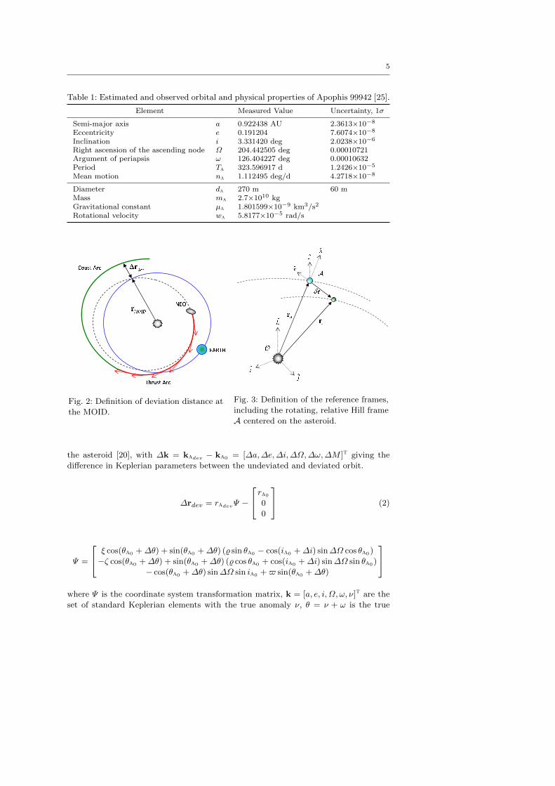
The minimum orbital intersection distance (MOID) is the separation distance at the
closest point between two orbits, e.g. Apophis and the Earth. The deviation distance
is defined here as the difference in position between the original, undeviated orbit ka0
and the deviated orbit kadev at tmoid [7] (see Fig. 2). Fig. 3 illustrates the definition
and nomenclature for the references frames used here.
Non-linear equations for were derived for determining the deviation vector ∆rdev =
radev − ra0 as a function of the ephemeris in the Hill reference frame A centred on
5
Table 1: Estimated and observed orbital and physical properties of Apophis 99942 [25].
Element Measured Value Uncertainty, 1σ
Semi-major axis a 0.922438 AU 2.3613×10⁻⁸
Eccentricity e 0.191204 7.6074×10⁻⁸
Inclination i 3.331420 deg 2.0238×10⁻⁶
Right ascension of the ascending node Ω 204.442505 deg 0.00010721Argument of periapsis ω 126.404227 deg 0.00010632Period Ta 323.596917 d 1.2426×10⁻⁵
Mean motion na 1.112495 deg/d 4.2718×10⁻⁸
Diameter da 270 m 60 mMass ma 2.7×10¹⁰ kgGravitational constant µa 1.801599×10⁻⁹ km3/s2
Rotational velocity wa 5.8177×10⁻⁵ rad/s
Fig. 2: Definition of deviation distance at
the MOID.
Fig. 3: Definition of the reference frames,
including the rotating, relative Hill frame
A centered on the asteroid.
the asteroid [20], with ∆k = kadev − ka0 = [∆a,∆e,∆i,∆Ω,∆ω,∆M ]t giving the
difference in Keplerian parameters between the undeviated and deviated orbit.
∆rdev = radevΨ −ra0
0
0
(2)
Ψ =
ξ cos(θa0 +∆θ) + sin(θa0 +∆θ) (% sin θa0 − cos(ia0 +∆i) sin∆Ω cos θa0)
−ζ cos(θa0 +∆θ) + sin(θa0 +∆θ) (% cos θa0 + cos(ia0 +∆i) sin∆Ω sin θa0)
− cos(θa0 +∆θ) sin∆Ω sin ia0 +$ sin(θa0 +∆θ)
where Ψ is the coordinate system transformation matrix, k = [a, e, i, Ω, ω, ν]t are the
set of standard Keplerian elements with the true anomaly ν, θ = ν + ω is the true

6
latitude, and,
$ = cos ia0 sin(ia0 +∆i)− cos∆Ω cos(ia0 +∆i) sin ia0 (3a)
% = sin ia0 sin(ia0 +∆i) + cos∆Ω cos(ia0 +∆i) cos ia0 (3b)
ξ = cos∆Ω cos θa0 + cos ia0 sin∆Ω sin θa0 (3c)
ζ = cos∆Ω sin θa0 − cos ia0 sin∆Ω cos θa0 (3d)
The change in the orbital parameters is calculated by numerically integrating the
Gauss planetary equations using a thrust vector udev = [uv un uh]t induced by the
deflection method:
∆k =
∫ ti
t0
dk(udev)
dtdt (4)
In the following we will assume that the deflection action is always aligned with the
heliocentric velocity of the asteroid, therefore un = 0 and uh = 0. The Gauss equations
k are given by [2],
da
dt=
2a2υ
µauv (5a)
de
dt=
1
υ
(2 (e+ cos ν) uv − ra sin ν
aun
)(5b)
di
dt=
ra cos θ
huh (5c)
dΩ
dt=
ra sin θ
h sin iuh (5d)
dω
dt=
1
eυ
(2 sin ν uv +
(2e+
raa cos ν
)un
)− ra sin θ cos i
h sin iuh (5e)
dν
dt=
h
r2− 1
eυ
(2 sin ν uv +
(2e+
raa
cos ν)
un
)(5f)
dM
dt= na −
√a p
eaυ
(2 sin ν
(1 + e2
rap
)ut +
ra cos ν
aun
)(5g)
with,
p = a√1 + e υ =
√2µ¯
ra− µ¯
ana =
√µ¯
a3
where na is the mean orbital motion of the asteroid, and µ¯ is the gravitational constant
of the Sun.
Colombo et al. [7] determined that the change in angular location, in this case given
by the mean anomaly, calculated at the MOID is,
∆M =
∫ ti
t0
dM
dtdt+ na0 (t0 − tmoid) + nai (tmoid − ti) (6)
Eq. (2) together with Eqs. (5) and (6) give the deviation of the orbit of the asteroid at
the time of the MOID, regardless of the actual position of the Earth, but not the close
approach or the minimum orbit interception distance with respect to the Earth. Vasile
and Colombo [39] demonstrated that a good estimation of the minimum interception
distance can be obtained by projecting the deviation onto the b-plane of the Earth
at the time of the MOID (assuming that the Earth is at the point of the MOID). In
7
the test section, therefore, we will present the variation of the impact parameter (or b
parameter) on the b-plane of the Earth.
The thrust produced by the deflection method is a direct function of the rate of
the expelled surface matter [34],
dmexp
dt= 2nscvrot
∫ ymax
y0
∫ tout
tin
1
H(Pin −Qrad −Qcond) dt dy (7)
where [tin, tout] is the duration for which a point is illuminated, [y0, ymax] are the limits
of the vertical illuminated surface area (i.e. orthogonal to the direction of rotation of
the asteroid), H is the enthalpy of sublimation, vrot is the linear velocity of a point as
it travels horizontally (i.e., orthogonal to y) through the illuminated spot area and nsc
is the number of spacecraft in the formation.
The input power per unit area due to the solar concentrators is given by,
Pin = σsysCr(1− ςa)S0
(raura
)2(8)
where ςa = 0.2 is the albedo of the asteroid, S0 = 1367 W/m2 is the solar flux at 1 AU
and scaled to the Sun-asteroid distance ra, σsys is the system efficiency, and Cr is the
concentration ratio (the ratio between the power density from the Sun on the mirror
surface, and that of the spot area on the asteroid).
The heat loss due to black-body radiation and the conduction loss are defined,
respectively, as,
Qrad = σεbbT4 (9)
Qcond = (Tsubl − T0)
√cakaρa
πt(10)
where σ is the Stefan-Boltzmann constant, εbb is the black body emissivity, T is the
temperature and ca, ρa and ka are, respectively, the heat capacity, density and thermal
conductivity of the asteroid. For the asteroid Apophis, ca = 750 J/kg·K based on the
average value for silicate materials, ka = 2 W/K/m and ρa = 2600 kg/m3 [30]. The
sublimation temperature assumed is that for forsterites, Tsubl = 1800 K [42], with
T0 set to 278 K. The induced acceleration due to the sublimation process can then
determined by [34],
usub =Λv mexp
mava (11)
where va is direction of velocity vector of the NEO, Λ ' (2π
)is the scattering factor,
v is the average velocity of the debris particles according to Maxwell’s distribution of
an ideal gas:
v =
√8kbTsubl
πMMg2SiO4
(12)
where kb is the Boltzmann constant, and MMg2SiO4is the molecular mass of fosterite.
The scattering factor is computed as the average of all possible thrust directions as-
suming that the thrust can point randomly at any angle αt between 0 and π, therefore
Λ = 1π
∫ π0cosαt dαt [34]. Note that some preliminary experiments demonstrate that
the plume is actually more focused. However, assuming a uniform distribution of the
thrust pointing direction over an angle of 180 degrees is a conservative choice.
The remaining mass of the asteroid ma is calculated by numerically integrating
Eq. (7). This induced acceleration udev is used with the Gauss equations in Eq. (5) in
order to determine the change in the NEO orbit due to the solar sublimation.
8
2.2 Contamination Model
The contamination of the mirror surfaces due to the debris plume is modeled based on
the work by Kahle et al. [17] The study is based on a number of initial assumptions
regarding the expansion of the plume and sublimation process. The first assumption
holds that the sublimation process is comparable to the generation of tails in comets.
The asteroid is assumed to contain a reservoir of material underneath the surface,
with the gas expanding both outwards as expected, and inwards through a throat
into vacuum within the asteroid itself. This assumption holds true, for example, for a
loose rubble-pile asteroid model. The second assumption is that the plume expansion
is similar to the expansion of gas of a rocket engine outside the nozzle.
The density of the expelled gas ρexp is computed analytically,
ρexp(rs/sc, ϕ) = jcmexp
v Aspot
(dspot
2δr + dspot
)2
(cosΘ)2/(κ−1) (13)
where rs/sc is the distance from the spot on the surface of the asteroid to the spacecraft,
and Θ = πϕ/2ϕmax where ϕ is the angle between the spot-spacecraft vector and the
y axis of the Hill reference frame. The jet constant jc was set to 0.345, the maximum
expansion angle ϕmax = 130.45, and adiabatic index κ = 1.4, based on the values for
diatomic particles [18].
The position vector rs/sc from the spot to the spacecraft is defined as:
rs/sc =
x+ rell sinwat cos(wat+ θva)− rell coswat sin(wat+ θva)
y − rell coswat cos(wat+ θva)− rell sinwat sin(wat+ θva)
z
(14)
where the radius of the ellipse is given by,
rell =aibi√(
bi cos(wat+ θva))2
+(ai sin(wat+ θva)
)2 (15)
and, with reference to Fig. 3, the position of the spacecraft with respect to the center
of the asteroid is δr = [x, y, z]T . We assume here that the asteroid is spinning around
the z axis with a rotational velocity wa. The direction of the velocity of the asteroid
in the heliocentric reference frame projected onto the Hill reference frame A is θva .
In other words, in order to have a deflection thrust aligned with the velocity of the
asteroid, the spot is assumed to be at an elevation angle over the y axis equal to θva .
The third assumption made is that all the particles impacting the surface of the
mirror condense and stick to the mirror. The exhaust velocity is constant, therefore
the thrust depends only on the mass flow. A higher thrust results in a higher mass
flow and thus in a faster contamination. Following the approach used to compute the
contamination of surfaces due to out-gassing, a view factor ψvf was added equal to the
angle between the normal to the mirror and the incident flow of gas. The resulting
variation of the thickness of the material condensing on the mirror can be computed
with:dhcnddt
=2 v ρexpρlayer
cosψvf (16)
The average debris velocity v is multiplied by a factor of 2 to account for the expansion
of the gas in a vacuum. The layer density ρlayer is to set to 1 g/cm3. The power
9
density on the asteroid surface is decreased based on the contamination of the mirrors.
A degradation factor τ is applied to the power beamed to the asteroid surface, based
on the Lambert-Beer-Bouguer law [17],
τ = exp−2ηhcnd (17)
where η = 104/cm is the absorption coefficient for forsterite. Eq. (16) is numerically
integrated, along with the Gauss equations in (5), for the period of the mission.
2.3 Tugging Effect
The spacecraft will librate at a distance δr from the asteroid, thus exerting a tugging
effect on it [37]. The tugging acceleration utug is given by:
utug = −nscGmsc
δr2δr (18)
where G is the universal gravity constant. The mass of the spacecraft msc is dictated
mainly by the overall mass of the mirror. It is assumed here that the mirror has an
area density of 0.6 kg/m2, and the dry mass of the bus is 500 kg [40]. A 30% margin
is added both to the total mass of the mirror and the overall mass of the spacecraft
(i.e., mirror plus bus) for contingency and orbit maintenance. The distance from the
asteroid depends on the required concentration ratio Cr. If the distance is constant
the concentration ratio will change with the distance from the Sun. On the contrary,
if the concentration ratio is kept constant then the spacecraft will have to move back
and forth towards the asteroid according to:
δr =dspot2ϑ¯
rscrau
cos εaepsin εaep
0
(19)
where dspot is the desired diameter of the illuminated spot area and ϑ¯ is the angular
radius of the Sun (at one AU, ϑ¯ = 4.53 mrad). The angle εaep is the elevation over
the y axis. Note that the movement should be librating inline the spot vector, but in
this paper we adopt the simplified movement in Eq. 19.
As an example, if we assume a concentration ratio Cr = 100 at aphelion with
a 62 m diameter mirror, we need to place the mirrors 750 m from the surface of the
asteroid which translates into a minimum distance of 890 m from its center (considering
bi). Thus, the tug acceleration at aphelion is utug,a = 2.52 × 10⁻¹³ m/s2 and at
perihelion is utug,p = 4.83 × 10⁻¹³ m/s2. If the concentration ratio is reduced to
Cr = 35 the minimum distance at perihelion can be brought up to about 1000 m and
therefore the tug acceleration becomes utug,p = 2.0 × 10⁻¹³ m/s2 at perihelion and
utug,p = 1.24× 10⁻¹³ m/s2 at aphelion.
3 Enhanced Yarkovsky Effect
If the power density is not high enough to sublimate the surface material, it may be
sufficient to heat up the surface creating a low thrust by means of the Yarkovsky effect.

10
Given the emissivity εa of the asteroid, the force due to the light projected onto the
asteroid is,
Flight = 2(1− ςa)nsc Λlight σsys CrAspot Ssrp
(raursc
)2+ nsc ςa σsys CrAspot Ssrp
(raursc
)2
= nsc σsys Am Ssrp
(raursc
)2 (2Λlight(1− ςa) + ςa
)(20)
where Ssrp = 4.562×10⁻⁶ N/m is the solar pressure at one astronomical unit, Aspot is
the 2D illuminated surface area on the asteroid, Am is the effective surface area of the
primary mirror that is perpendicular to the Sun, Cr = Am/Aspot is the concentration
ratio, Λlight = 4/(3π) is the scattering factor and nspot is the number of illuminated
spot areas. The first component is the reflected light and the second component is the
absorbed light. The scattering factor is the average of the reflected force assuming that
the reflection can have any direction angle αl between [0, π]. Therefore, the scattering
factor here is defined as Λlight =1π
∫ π0cos3 αl dαl. The number of spots nspot is equal
to the number of spacecraft if no sublimation is attempted, and equal to 1 if the
spacecraft tries to induce a sublimation of the surface.
For an asteroid surface temperature Ta, the emission of photons will add a force
component Fir [3],
Fir = nspotΛεaσT
4a
cAspot (21)
where c is the speed of light. The temperature of the spot surface can be computed
with the simple one-dimensional model [34]:
χa∂2T
∂x2=
∂T
∂t(22)
where χa is the thermal diffusivity of the material given by,
χa =ka
ρacA
The boundary conditions are,
−ka∂Ta
∂xspot+ εaσT
4a = ςaσsysCrS0
(raursc
)2(23a)
T (0, x) = T0 (23b)
T (t, L) = T0 (23c)
The initial surface temperature T0 is 278 K, which is assumed here to be constant from
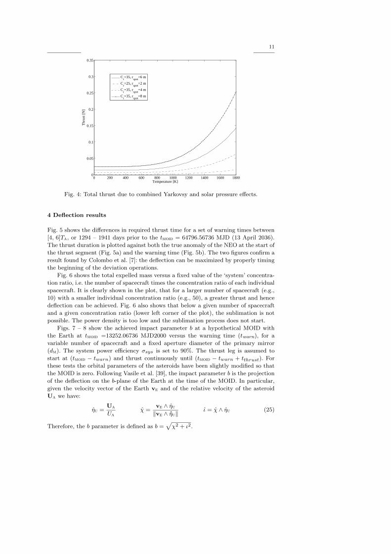
the surface down to a depth of L = 135 m inside the asteroid. Fig. 4 shows the sum of
the two force components Fir and Flight as a function of the surface temperature for
different spot sizes and concentration ratios.
The total deflection acceleration acting on the asteroid is therefore:
udev = usub + utug +Flight + Fir
mava (24)
11
0 200 400 600 800 1000 1200 1400 1600 18000
0.05
0.1
0.15
0.2
0.25
0.3
0.35
Temperature [K]
Thr
ust [
N]
Cr=35, r
spot=6 m
Cr=25, r
spot=2 m
Cr=35, r
spot=4 m
Cr=35, r
spot=8 m
Fig. 4: Total thrust due to combined Yarkovsy and solar pressure effects.
4 Deflection results
Fig. 5 shows the differences in required thrust time for a set of warning times between
[4, 6]Ta, or 1294 – 1941 days prior to the tmoid = 64796.56736 MJD (13 April 2036).
The thrust duration is plotted against both the true anomaly of the NEO at the start of
the thrust segment (Fig. 5a) and the warning time (Fig. 5b). The two figures confirm a
result found by Colombo et al. [7]: the deflection can be maximized by properly timing
the beginning of the deviation operations.
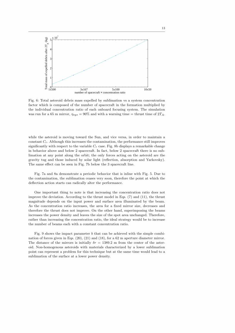
Fig. 6 shows the total expelled mass versus a fixed value of the ‘system’ concentra-
tion ratio, i.e. the number of spacecraft times the concentration ratio of each individual
spacecraft. It is clearly shown in the plot, that for a larger number of spacecraft (e.g.,
10) with a smaller individual concentration ratio (e.g., 50), a greater thrust and hence
deflection can be achieved. Fig. 6 also shows that below a given number of spacecraft
and a given concentration ratio (lower left corner of the plot), the sublimation is not
possible. The power density is too low and the sublimation process does not start.
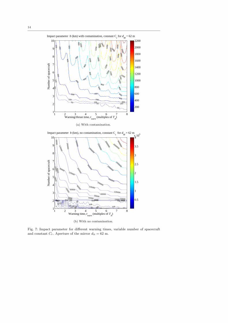
Figs. 7 – 8 show the achieved impact parameter b at a hypothetical MOID with
the Earth at tmoid =13252.06736 MJD2000 versus the warning time (twarn), for a
variable number of spacecraft and a fixed aperture diameter of the primary mirror
(dm). The system power efficiency σsys is set to 90%. The thrust leg is assumed to
start at (tmoid − twarn) and thrust continuously until (tmoid − twarn + tthrust). For
these tests the orbital parameters of the asteroids have been slightly modified so that
the MOID is zero. Following Vasile et al. [39], the impact parameter b is the projection
of the deflection on the b-plane of the Earth at the time of the MOID. In particular,
given the velocity vector of the Earth ve and of the relative velocity of the asteroid
Ua we have:
ηu =Ua
Uaχ =
ve ∧ ηu‖ve ∧ ηu‖ ι = χ ∧ ηu (25)
Therefore, the b parameter is defined as b =√
χ2 + ι2.

12
−3 −2 −1 0 1 2 3
50
100
150
200
True anomaly of NEO at t0 (rad)
Req
uire
d th
rust
dur
atio
n (d
ays)
(a)
1500 1600 1700 1800 1900 2000 2100
50
100
150
200
Warning time before impact (days)
Req
uire
d th
rust
dur
atio
n (d
ays)
(b)
Fig. 5: Effect of orbital location at the start of thrust period, on the required duration
to achieve a deflection of 10000 km at tmoid = 64796.56736 MJD using a single 65 m
mirror with a concentration ratio Cr = 98.
Fig. 7 compares the achievable impact parameter b with and without contamination
assuming a variable Cr. This situation occurs when the mirrors are at a constant
distance from the asteroid. In this case the focusing capability of the mirror changes
with the distance from the Sun since the angular diameter of the Sun increases, or
decreases, as the asteroid moves closer, or farther away. The mirrors are assumed to
be at an angular distance of ϕ = 60 with respect to the y axis and at a distance
δr = 694.62 m from the center of the asteroid. Although the mirrors are not directly
in the plume, according to Kahle’s model the contamination is still quite substantial
and the power density quickly falls below the required limit to induce the sublimation.
The mirrors will continue to heat up the asteroid but no sublimation will occur.
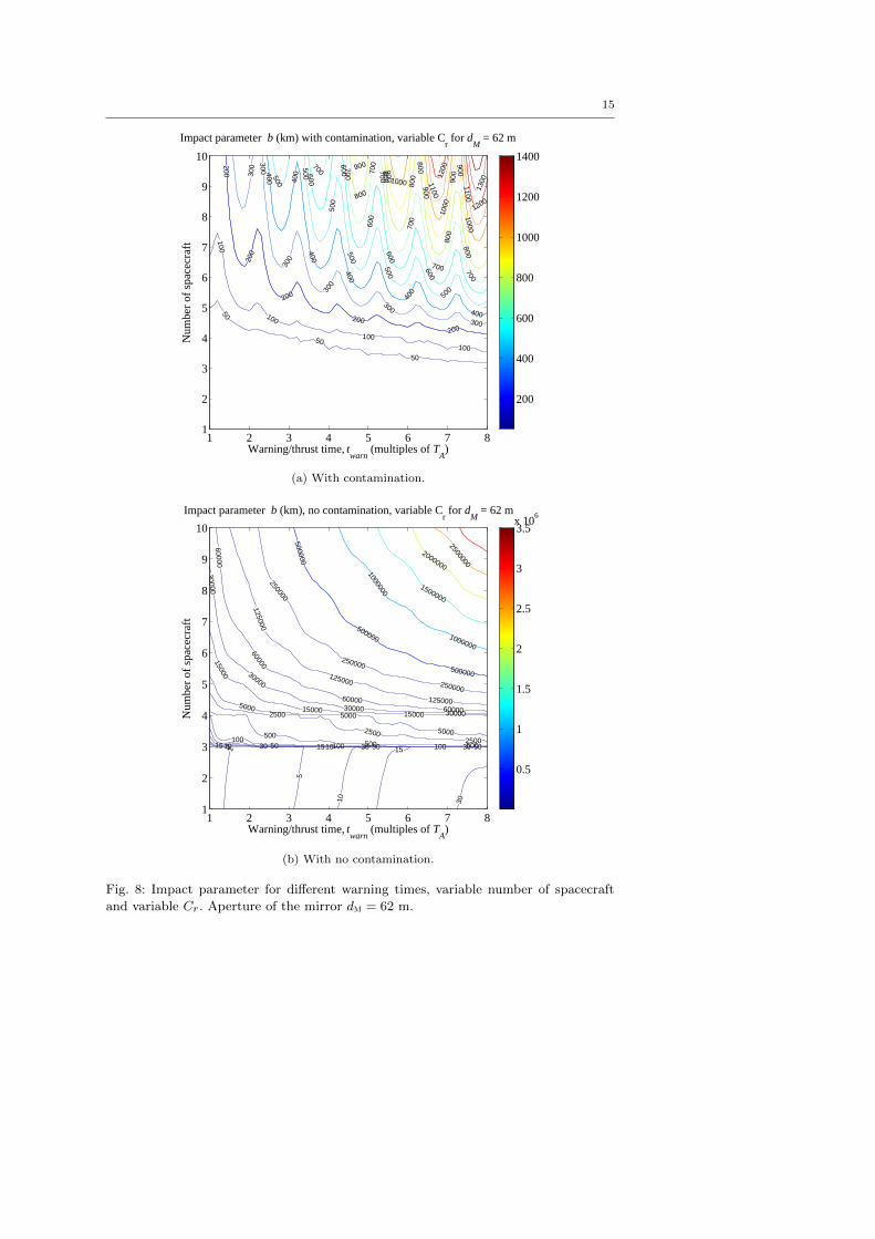
Fig. 8 compares the achievable impact parameter b with and without contamina-
tion assuming a constant Cr. In this case the mirrors are moving toward the asteroid
13
1x500 3x167 5x100 10x500
1
2
3
4
5x 10
7
number of spacecraft × concentration ratio
Tot
al m
ass
of e
xpel
led
debr
is a
fter
2T A
(kg
)
Fig. 6: Total asteroid debris mass expelled by sublimation vs a system concentration
factor which is composed of the number of spacecraft in the formation multiplied by
the individual concentration ratio of each onboard focusing system. The simulation
was run for a 65 m mirror, ηsys = 90% and with a warning time = thrust time of 2TA.
while the asteroid is moving toward the Sun, and vice versa, in order to maintain a
constant Cr. Although this increases the contamination, the performance still improves
significantly with respect to the variable Cr case. Fig. 8b displays a remarkable change
in behavior above and below 2 spacecraft. In fact, below 2 spacecraft there is no sub-
limation at any point along the orbit; the only forces acting on the asteroid are the
gravity tug and those induced by solar light (reflection, absorption and Yarkovsky).
The same effect can be seen in Fig. 7b below the 3 spacecraft line.
Fig. 7a and 8a demonstrate a periodic behavior that is inline with Fig. 5. Due to
the contamination, the sublimation ceases very soon, therefore the point at which the
deflection action starts can radically alter the performance.
One important thing to note is that increasing the concentration ratio does not
improve the deviation. According to the thrust model in Eqs. (7) and (11), the thrust
magnitude depends on the input power and surface area illuminated by the beam.
As the concentration ratio increases, the area for a fixed mirror size, decreases and
therefore the thrust does not improve. On the other hand, superimposing the beams
increases the power density and leaves the size of the spot area unchanged. Therefore,
rather than increasing the concentration ratio, the ideal strategy would be to increase
the number of beams each with a constant concentration ratio.
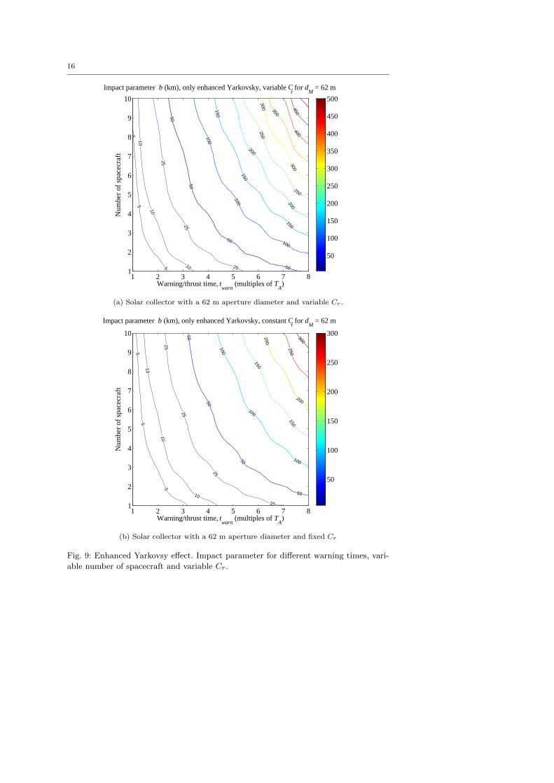
Fig. 9 shows the impact parameter b that can be achieved with the simple combi-
nation of forces given in Eqs. (20), (21) and (18), for a 62 m aperture diameter mirror.
The distance of the mirrors is initially δr = 1389.2 m from the center of the aster-
oid. Non-homogenous asteroids with materials characterized by a lower sublimation
point can represent a problem for this technique but at the same time would lead to a
sublimation of the surface at a lower power density.
14
50
50 50
50
100
100100
100
200200
200
200200
400
400
400
400
400
600
600
600
600
600
800
800
800
800
800
1000
1000
1000
1000
1000
1200
1200
1200
1200 1200
1400
1400
140014
00
1400
1600
160016
00
1600
1800
18002000
Warning/thrust time, twarn
(multiples of TA)
Num
ber
of s
pace
craf
t
Impact parameter b (km) with contamination, constant Cr for d
M = 62 m
1 2 3 4 5 6 7 81
2
3
4
5
6
7
8
9
10
200
400
600
800
1000
1200
1400
1600
1800
2000
2200
(a) With contamination.
15
5
10
10
1515
15
2020
20
2525
25
303030
50
50
5050
100
100100
500 500 5002500 2500 2500
5000
50005000 5000
15000
15000
1500015000
30000
30000
3000030000
60000
60000
60000
60000
125000
125000
125000
125000
250000
250000
250000
500000
500000
500000
1000000
1000000
1500000
1500000
2000000
2500000
3000000
Warning time, twarn
(multiples of TA)
Num
ber
of s
pace
craf
t
Impact parameter b (km), no contamination, constant Cr for d
M = 62 m
1 2 3 4 5 6 7 81
2
3
4
5
6
7
8
9
10
0.5
1
1.5
2
2.5
3
3.5
4x 10
6
(b) With no contamination.
Fig. 7: Impact parameter for different warning times, variable number of spacecraft
and constant Cr. Aperture of the mirror dm = 62 m.
15
50
50
50
100
100
100
100
200
200
200
200
200
300
300
300
300
300
300
400 400
400
400
400
400
500
500
500
500
500
500
600
600
600
600
600
700
700 700
700
700
700 700
800
800
800
80080
0
800
900 900
90090
0
900
1000
1000
1000
1100
1100
1200
1200
1300
Warning/thrust time, twarn
(multiples of TA)
Num
ber
of s
pace
craf
t
Impact parameter b (km) with contamination, variable Cr for d
M = 62 m
1 2 3 4 5 6 7 81
2
3
4
5
6
7
8
9
10
200
400
600
800
1000
1200
1400
(a) With contamination.
1
5
5
10
1010 151515
30
30 30 3050 50 50100
100 100
500500 500
2500
25002500
50005000
5000
15000
15000 15000
30000
30000
3000030000
60000
60000
6000060000
125000
125000
125000
250000
250000
250000
500000
500000
500000
1000000
1000000
1500000
2000000
2500000
Warning/thrust time, twarn
(multiples of TA)
Num
ber
of s
pace
craf
t
Impact parameter b (km), no contamination, variable Cr for d
M = 62 m
1 2 3 4 5 6 7 81
2
3
4
5
6
7
8
9
10
0.5
1
1.5
2
2.5
3
3.5x 10
6
(b) With no contamination.
Fig. 8: Impact parameter for different warning times, variable number of spacecraft
and variable Cr. Aperture of the mirror dm = 62 m.
16
5
55
10
10
10
25
25
25
50
50
50
50
100
100
100
150
150
150
200
200
250
250
300
300
350
400450
Warning/thrust time, twarn
(multiples of TA)
Num
ber
of s
pace
craf
t
Impact parameter b (km), only enhanced Yarkovsky, variable Cr for d
M = 62 m
1 2 3 4 5 6 7 81
2
3
4
5
6
7
8
9
10
50
100
150
200
250
300
350
400
450
500
(a) Solar collector with a 62 m aperture diameter and variable Cr.
55
5
10
10
10
25
25
25
25
50
50
50
50
100
100
100
150
150
200
200
250
300
Warning/thrust time, twarn
(multiples of TA)
Num
ber
of s
pace
craf
t
Impact parameter b (km), only enhanced Yarkovsky, constant Cr for d
M = 62 m
1 2 3 4 5 6 7 81
2
3
4
5
6
7
8
9
10
50
100
150
200
250
300
(b) Solar collector with a 62 m aperture diameter and fixed Cr
Fig. 9: Enhanced Yarkovsy effect. Impact parameter for different warning times, vari-
able number of spacecraft and variable Cr.
17
5 Mirror Dynamics and Control
In order to obtain the desired deviation, the mirrors need to be placed and controlled
in the proximity of the asteroid. In particular, the location of the mirror must be such
that the plume impingement is minimized and the power density is maximized. In the
proximity of the asteroid, in a Hill rotating reference frame, the spacecraft are subject
to the force due to solar pressure, the gravity of the asteroid, the gravity of the Sun,
the centrifugal and Coriolis forces plus the forces induced by the impingement either
with the plume or the re-emitted and reflected light from the asteroid. The mirrors can
be designed such that the resultant of all these forces is minimal. An active control can
then be added to maintain the spacecraft librating above the surface of the asteroid.
Following the ellipsoidal asteroid model, we assume that the semi-axis ci is aligned
with the z-axis of the asteroid Hill frame A (see Figure 3) and that the asteroid rotates
around the z-axis with angular velocity wa. The gravity field of the asteroid is expressed
as the sum of a spherical field plus a second-degree and second-order field [14,31],
U20+22 =µa
δr3
(C20 (1− 3
2cos2 γ) + 3C22 cos2 γ cos 2λ
)(26)
where the harmonic coefficients C20 and C22 are a function of the semi-axes,
C20 = − 1
10(2c2i − a2i − b2i ) (27a)
C22 =1
20(a2i − b2i ) (27b)
and λ is defined as,
λ = arctan(y
x
)+ wa t
with γ = 0 since only the in-plane motion is considered.
If we consider a Hill reference frame A centered in the barycenter of the asteroid
(see Figure 3), the motion of the spacecraft in the proximity of the asteroid is given
by:
x = −rA + 2νy + ν2(ra + x) + νy − µ¯(ra + x)
r3sc− µa
δr3x+
Fsx(x, y, z)
msc+
∂U20+22
∂x(28a)
y = −2νx− ν(ra + x) + ν2y − µ¯
r3scy − µa
δr3y +
Fsy (x, y, z)
msc+
∂U20+22
∂y(28b)
z = −µ¯
r3scz − µa
δr3z +
Fsz (x, y, z)
msc+
∂U20+22
∂z(28c)
with,
ν =udevy
− 2raraν
r2a(29)
ra = ν2ra − µ¯
r2a+ udevx (30)
The force term Fs = [Fsx Fsy Fsz ]t is made of three contributions: direct light pressure
from the Sun Fsrp, light pressure from the emitted and reflected light from the asteroid
Flight and the force due to the flow of gas and debris coming from the asteroid Fplume.
18
In order to have equilibrium, Fs should be aligned with the gravity vector and
apparent forces, but in the opposite direction. Examining Eq. (28c), it is clear that z is
zero when z = 0, therefore in the remainder of this section we will focus on the motion
in the x-y plane.
For a direct reflection of the light onto the NEO surface, the focal point is along the
mirror-asteroid direction with a magnitude roughly equal to the distance between the
mirror and the asteroid. For such a long focal distance, the resulting mirror is almost
flat. Assuming a perfect reflection, the force Fsrp is:
Fsrp = 2AmSsrp
(raursc
)2cos2 β
cosβ
sinβ
0
(31)
The angle β is the half angle between the asteroid-mirror vector and the Sun-mirror
vector (which is approximated by setting it equal to the Sun-asteroid vector).
β =1
2arctan
(rs/sc,y
rs/sc,x
)(32)
where rs/sc,y and rs/sc,x are respectively the y and x components of the vector rs/sc.
The force due to the light coming from the asteroid can be expressed in the following
form:
Flight = 2nspot
(Λ
εaσT4a
c + Λlight(1− ςa)σsysCrSsrp(raursc
)2)Aspot
2πr2s/sc
Am cos2 β
cosβ
sinβ
0
(33)
where nspot is the number of spot areas emitting and reflecting light. The assumption
is made that the radiation is uniformly distributed over a hemisphere. Note that in
the case of the enhanced Yarkovsky effect nspot = nsc while in the case of sublimation
nspot = 1. The force due to the two contributions of light pressure is aligned with the
asteroid-mirror direction. Moreover, the modulus of the light pressure is a function of
the distance from the Sun.
If the flow rate per unit area at distance rs/sc is (2ρexp(rs/sc, ϕ)v) and all the
particles stick to the surface of the mirror then the force Fplume is:
Fplume = 4ρexp(rs/sc, ϕ)v2Am cosψvf rs/sc (34)
and is aligned with the rs/sc. However, the flow rate depends on the power density
and therefore on the distance from the Sun. Given these equations, the resultant of all
the forces acting on the spacecraft is not zero and in particular the difference between
gravity and Fs is a function of time. Therefore, an active control is required to maintain
the position of the spacecraft with respect to the asteroid.
The force due to the light coming from the asteroid can be up to 1.6948×10⁻⁵ N at
perihelion for a Cr = 35, rs/sc = 857 m and nsc = 1 and grows up to 2.0337× 10⁻⁴ N
for nsc = 12. It is therefore two to three orders of magnitude lower than the force in
Eq. (31), which, for similar operating conditions, is 2.636×10⁻² N. The force due to gas
and debris instead is Fplume = 3.533×10⁻³ N for nsc = 4 and Fplume = 3.727×10⁻² N
for nsc = 9, with Cr = 100, the mirrors at a distance rs/sc = 507 m and an elevation
angle of 60. Therefore, the force due to the plume is not negligible for a high number
of spacecraft.

19
If we assume that Flight, centrifugal and Coriolis forces are negligible compared
to solar pressure, gravity of the asteroid, and plume and that any non-spherical terms
in the gravity field expansion result in only a small perturbation, then we can build a
simple control law based on the Lyapunov control function:
V =1
2δv2 +
1
2K
((x− xaep)
2 + (y − yaep)2 + (z − zaep)
2)
(35)
where δraep = [xaep, yaep, zaep]t are the coordinates of the artificial equilibrium point
at which we want to place the mirror (in the Hill frame). Now if there exist a control u
such that dV/dt < 0 then we can maintain the mirror in the proximity of the artificial
equilibrium point. A possible control is given by:
u = −(− µa
δr3δr+
Fsrp
msc+
Fplume
msc
)−K (δr− δraep)− cdδv (36)
The total derivative of the function V is:
dV
dt= δvT δv + k(δr− δraep)
T δv (37a)
= δvT
(− µa
δr3δr+
Fsrp
msc+
Fplume
msc−(− µa
δr3δr+
Fsrp
msc+
Fplume
msc
)(37b)
−K (δr− δraep)− cdδv
)+K(δr− δraep)
T δv
= −cdδvT δv < 0 (37c)
where δv = [x, y, z]t is the relative velocity of the spacecraft in the asteroid Hill
reference frame A.
We can now introduce the control equation (36) into the full dynamic model in
Eq. (28) and test the validity of the assumption on that the perturbations given by
centrifugal, Coriolis forces, light coming from the asteroid and aspherical gravity field
are indeed small. The result is represented in Figs. 10a, 11a for the case in which the
AEP is maintained at a fixed distance from the asteroid. Figs. 10b, 11b represent,
instead, the result of the application of the Lyapunov controller when a different AEP
is selected along the the asteroid-mirror direction at different instants of time during
the year.
The elastic coefficient K for both cases was chosen to be 10−6 while the dissipative
coefficient cd was set to 10−5. The latter strategy maintains a constant concentration
ratio while the asteroid moves closer and farther from the Sun. In order to maintain a
constant Cr, the focal length has to be modified according to the angular diameter of
the Sun seen from the mirror.
Fig. 10b shows that the the controller is able to maintain the mirror in close prox-
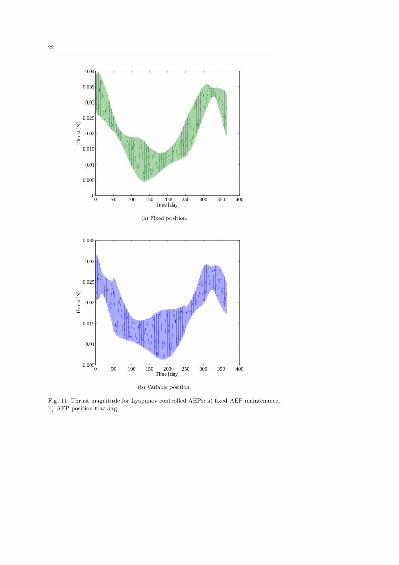
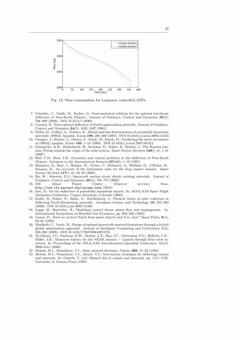
imity to the radial direction, effectively chasing the position of the AEP. Figs. 11b
and 12 represent the modulus of the thrust and the mass consumption for a one year
of operation of a 3005 kg spacecraft, carrying a mirror with an aperture diameter of
62 m. The required peak thrust is above 40 mN, with a total mass consumption of
about 15.0 kg, assuming an engine Isp of 4500 s, for maintaining a fixed position. For
chasing the position of the AEP’s, instead, the required peak thrust is about 35 mN,
with a total mass consumption of about 12.0 kg a year.
20
These figures demonstrate that with a very small electric propulsion system, the
mirror position can be maintained at the desired proximity to the asteroid. Note that
the thrust is acting towards the asteroid mainly to compensate for the force due to
solar pressure.
6 Final Remarks
This paper presented an analysis of the performance of an asteroid deflection method
based on the sublimation of surface matter through a concentrated solar beam. Ac-
cording to the available model for the sublimation process, the obtainable deflection
is limited by the contamination of the reflector even if the reflector is not directly in
the plume of expelled gas. Using multiple spacecraft improves the deflection but does
not solve the contamination problem. On the other hand, this study showed that even
when the power density is not enough to ignite the sublimation process, the increase in
the Yarkovsky effect combined with the enhanced light pressure generates a reasonable
deflection comparable to the solution generated with the sublimation of the surface in
the case of contamination of the mirrors. This study also demonstrated that a constant
concentration ratio solution, with variable distance of the mirrors from the target, is
more effective than a constant position solution. A Lyapunov controller was developed
to allow the control of the position of the mirrors at a very low propellant cost.
The results in this paper demonstrate that the solar sublimation system is severely
penalized by the contamination of the reflector. Although, the system is always able
to generate a deflection of several hundred kilometers, the total mass into space can
make the system non-competitive against other deflection methods. A more accurate
contamination model is necessary to assess the actual applicability of this deflection
approach. A solution to the contamination problem would make this deflection ap-
proach extremely effective for medium size asteroids. On the other hand, a contained
system with a small number of spacecraft enhancing the Yarkovsky effect can provide
a deflection comparable to a gravity tractor for the same class of asteroids.
Acknowledgements The authors would like to thank Dr Leopold Summerer from the ESA/ESTECAdvanced Concepts Team for his support and advice.
References
1. Barucci, M., Yoshikawa, M., Michel, P., Kawagushi, J., Yano, H., Brucato, J., Franchi, I.,Dotto, E., Fulchignoni, M., Ulamec, S.: MARCO POLO: Near Earth Object sample returnmission. Experimental Astronomy 23(3), 785–808 (2009)
2. Battin, R.H.: An Introduction to the Mathematics and Methods of Astrodynamics. Revisededn. AIAA Education Series (1999)
3. Broz, M.: Yarkovsky effect and the dynamics of the solar system. PhD thesis, Facultyof Mathematics and Physics, Astronomical Institute, Charles University, Prague, CzechRepublic (2006)
4. Carusi, A., Valsecchi, G.B., D’abramo, G., Bottini, A.: Deflecting NEOs in route of collisionwith the Earth. Icarus 159(2), 417–422 (2002). DOI 10.1006/icar.2002.6906
5. Chesley, S.R.: Potential impact detection for near-Earth asteroids: The case of 99942Apophis (2004 MN4). In: Asteroids, Comets, Meteors Proceedings, vol. 229, pp. 215–228.IAU Symposium (2005)
6. Colombo, C., Vasile, M., Radice, G.: Optimal low-thrust trajectories to asteroids throughan algorithm based on differential dynamic programming. Celestial Mechanics and Dy-namical Astronomy 105(1–3), 75–112 (2009)

21
−352 −351.5 −351 −350.5 −350 −349.5 −349 −348.5 −348597.5
598
598.5
599
599.5
600
600.5
601
601.5
602
602.5
y displacement [m]
x di
spla
cem
ent [
m]
(a) Fixed position.
−400 −350 −300 −250400
450
500
550
600
650
700
y displacement [m]
x di
spla
cem
ent [
m]
(b) Variable position.
Fig. 10: Variation in position over one orbit shown in the local mirror reference frame,
for Lyapunov controlled AEPs: a) fixed AEP maintenance, b) AEP position tracking.
22
0 50 100 150 200 250 300 350 4000
0.005
0.01
0.015
0.02
0.025
0.03
0.035
0.04
Time [day]
Thr
ust [
N]
(a) Fixed position.
0 50 100 150 200 250 300 350 4000.005
0.01
0.015
0.02
0.025
0.03
0.035
Time [day]
Thr
ust [
N]
(b) Variable position.
Fig. 11: Thrust magnitude for Lyapunov controlled AEPs: a) fixed AEP maintenance,
b) AEP position tracking .
23
0 50 100 150 200 250 300 350 4002990
2995
3000
3005
Time [day]
Mas
s [k
g]
constant positionvariable position
Fig. 12: Mass consumption for Lyapunov controlled AEPs.
7. Colombo, C., Vasile, M., Radice, G.: Semi-analytical solution for the optimal low-thrustdeflection of Near-Earth Objects. Journal of Guidance, Control and Dynamics 32(3),796–809 (2009). DOI 10.2514/1.40363
8. Conway, B.: Near-optimal deflection of Earth-approaching asteroids. Journal of Guidance,Control and Dynamics 24(5), 1035–1037 (2001)
9. Delbo, M., Cellino, A., Tedesco, E.: Albedo and size determination of potentially hazardousasteroids: (99942) Apophis. Icarus 188, 266–269 (2007). DOI 10.1016/j.icarus.2006.12.024
10. Giorgini, J., Benner, L., Ostroa, S., Nolan, M., Busch, M.: Predicting the earth encountersof (99942) apophis. Icarus 193, 1–19 (2008). DOI 10.1016/j.icarus.2007.09.012
11. Glassmeier, K.H., Boehnhardt, H., Koschny, D., Kuhrt, E., Richter, I.: The Rosetta mis-sion: Flying towards the origin of the solar system. Space Science Reviews 128(1–4), 1–21(2007)
12. Hall, C.D., Ross, I.M.: Dynamics and control problems in the deflection of Near-EarthObjects. Advances in the Astronautical Sciences 67(640), 1–18 (1997)
13. Hampton, D., Baer, J., Huisjen, M., Varner, C., Delamere, A., Wellnitz, D., A’Hearn, M.,Klaasen, K.: An overview of the instrument suite for the deep impact mission. SpaceScience Reviews 117(1–2), 43–93 (2005)
14. Hu, W., Scheeres, D.J.: Spacecraft motion about slowly rotating asteroids. Journal ofGuidance, Control and Dynamics 25(4), 765–775 (2002)
15. IAU Minor Planet Center: Observer services: Neos.http://www.cfa.harvard.edu/iau/mpc.html (2010)
16. Izzo, D.: On the deflection of potentially hazardous objects. In: AIAA/AAS Space FlightMechanics Conference. Copper Mountain, Colorado (2005)
17. Kahle, R., Kuhrt, E., Hahn, G., Knollenberg, J.: Physical limits of solar collectors indeflecting Earth-threatening asteroids. Aerospace Science and Technology 10, 253–263(2006). DOI 10.1016/j.ast.2005.12.004
18. Legge, H., Boettcher, R.: Modelling control thrust plume flow and impingement. In:International Symposium on Rarefied Gas Dynamics, pp. 983–992 (1982)
19. Lunan, D.: Need we protect Earth from space objects and if so, how? Space Policy 8(1),90–91 (1992)
20. Maddock, C., Vasile, M.: Design of optimal spacecraft-asteorid formations through a hybridglobal optimization approach. Journal of Intelligent Computing and Cybernetics 1(2),239–268 (2008). DOI 10.1108/17563780810874735
21. McAdams, J.V., Dunham, D.W., Mosher, L.E., Ray, J.C., Antreasian, P.G., Helfrich, C.E.,Miller, J.K.: Maneuver history for the NEAR mission — Launch through Eros orbit in-sertion. In: Proceedings of the AIAA/AAS Astrodynamics Specialist Conference, AIAA-2000-4141 (2000)
22. Melosh, H.J., Nemchinov, I.V.: Solar asteroid diversion. Nature 366, 21–22 (1993)23. Melosh, H.J., Nemchinov, I.V., Zetzer, Y.I.: Non-nuclear strategies for deflecting comets
and asteroids. In: Gehrels, T. (ed.) Hazard due to comets and asteroids, pp. 1111–1132.University of Arizona Press (1994)
24
24. Nakamura, A.M., Michel, P.: Asteroids and their collisional disruption. In: Lecture Notesin Physics, Small Bodies in Planetary Systems, pp. 1–27. Springer Berlin / Heidelberg(2009)
25. NASA Near Earth Object program: 99942 Apophis (2004 MN4) impact risk. Onlinedatabase, http://neo.jpl.nasa.gov/risk/a99942.html (2010)
26. Near-Earth Object Science Definition Team: Study to determine the feasibility of extendingthe search for Near-Earth Objects to smaller limiting diameters. Tech. rep., NationalAeronautics and Space Administration (NASA) (2003)
27. Park, S.Y., Mazanek, D.D.: Deflection of Earth-crossing asteroids/comets using rendezvousspacecraft and laser ablation. Journal of Astronautical Sciences 53(1), 21–37 (2005)
28. Perozzi, E., Casalino, L., Colasurdo, G., Rossi, A., Valsecchi, G.: Resonant fly-by missionsto Near Earth Asteroids. Celestial Mechanics and Dynamical Astronomy 83(1–4) (2002)
29. Rayman, M., Varghese, P., Lehman, D., Livesay, L.: Results from the Deep Space 1 tech-nology validation mission. Acta Astronautica 47(2), 475–487 (2000)
30. Remo, J.L.: Classifying and modeling NEO material properties and interactions. In:Gehrels, T., Matthews, M.S., Schumann, A. (eds.) Hazards due to comets and asteroids,Space Science Series, pp. 551–596. University of Arizona Press, Tucson, AZ (1994)
31. Rossi, A., Marzari, F., Farinella, P.: Orbital evolution around irregular bodies. Earth,Planets, Space 51, 1173–1180 (1999)
32. Russell, C.T., Capaccioni, F., Coradini, A., de Sanctis, M.C., Feldman, W.C., Jaumann,R., Keller, H.U., McCord, T.B., McFadden, L.A., Mottola, S., Pieters, C.M., Prettyman,T.H., Raymond, C.A., Sykes, M.V., Smith, D.E., Zuber, M.T.: Dawn mission to Vesta andCeres. Earth, Moon, and Planets 101(1–2), 65–91 (2007)
33. Sanchez, J.P., Vasile, M., Radice, G.: Consequences of asteroid fragmentation duringimpact hazard mitigation. Journal of Guidance, Control and Dynamics (2010). DOI10.2514/1.43868
34. Sanchez Cuartielles, J.P., Colombo, C., Vasile, M., Radice, G.: Multi-criteria compari-son among several mitigation strategies for dangerous Near Earth Objects. Journal ofGuidance, Control and Dynamics 32(1), 121–142 (2009). DOI 10.2514/1.36774
35. Scheeres, D.J., Schweickart, R.L.: The mechanics of moving asteroids. In: Planetary De-fense Conference: Protecting Earth from Asteroids. AIAA, Orange County, California(2004)
36. Schweickart, R.L.: A call to (considered) action: International space development confer-ence. Occasional Paper 0501, B612 Foundation (2005)
37. Shengping Gong, J.L., BaoYin, H.: Formation flying solar-sail gravity tractors in displacedorbit for towing near-earth asteroids. Celestial Mechanics and Dynamical Astronomy105(1–3), 159–177 (2009)
38. Stephan, T.: Assessing the elemental composition of comet 81P/Wild 2 by analyzing dustcollected by Stardust. Space Science Reviews 138(1–4), 247–258 (2008)
39. Vasile, M., Colombo, C.: Optimal impact strategies for asteroid deflection. Journal ofGuidance, Control and Dynamics 31(4), 858–872 (2008). DOI 10.2514/1.33432
40. Vasile, M., Maddock, C., Radice, G., McInnes, C.: Call for ideas: NEO Encounter 2029,NEO deflection through a multi-mirror system. Tech. Rep. Ariadna ID: 08/4301, ContractNumber: 21665/08/NL/CB, ESA/ESTEC Advanced Concepts Team (2009)
41. Vokrouhlicky, D., Chesley, S., Milani, A.: On the observability of radiation forces actingon near-Earth asteroids. Celestial Mechanics and Dynamical Astronomy 81(1–2), 149–165(2001)
42. Wang, J., Davis, A., Clayton, R., Hashimoto, A.: Evaporation of single crystalforsterite: Evaporation kinetics, magnesium isotope fractionation, and implications ofmass-dependent isotopic fractionation of a diffusion-controlled reservoir. Geochimica etCosmochimica Acta 63(6), 953–966 (1999). DOI 10.1016/S0016-7037(98)00286-5
43. Yoo, S.M., Song, Y.J., Park, S.Y., Choi, K.H.: Spacecraft formation flying for earth-crossing object deflections using a power limited laser ablating. Advances in Space Re-search 43, 1873–1889 (2009). DOI 10.1016/j.asr.2009.03.025