on task relocation in two-dimensional meshes
TRANSCRIPT

Journal of Parallel and Distributed Computing 60, 616�638 (2000)
On Task Relocation in Two-Dimensional MeshesSeong-Moo Yoo
Department of Computer Science, Columbus State University,Columbus, Georgia 31907
E-mail: syoo�colstate.edu
Hyunseung Choo
School of Electrical and Computer Engineering, Sungkyunkwan University, Suwon, KoreaE-mail: choo�ece.skku.ac.kr
and
Hee Yong Youn, Chansu Yu, and Younghee Lee
School of Engineering, Information and Communications University, Taejon, KoreaE-mail: youn�icu.ac.kr; cyu�icu.ac.kr; yhlee�icu.ac.kr
Received February 2, 1998; accepted October 5, 1999
In parallel computer systems with a number of processors, externalfragmentation is caused by continuous allocation and deallocation of proces-sors to tasks which require exclusive use of several contiguous processors.With this condition, the system may not be able to find contiguous proces-sors to be allocated to an incoming task even with a sufficient number of freeprocessors. Relocation is an approach for alleviating this problem byreassigning the running tasks to other processors. In this paper, we examinetwo relocation schemes��full relocation and partial relocation scheme��fortwo-dimensional meshes. The full relocation scheme is desirable when thesystem is highly fragmented, while the partial relocation scheme is usedfor minimizing the number of relocated tasks. For the relocation process, weformally define and use two basic submesh movement operations��shiftingand rotating. Comprehensive computer simulation reveals that the proposedschemes are beneficial when the relocation overhead is not high, which ismachine dependent. � 2000 Academic Press
Key Words: external fragmentation; full and partial relocation scheme;mesh-connected systems; task allocation and deallocation; task relocation.
1. INTRODUCTION
Among several important interconnection topologies developed for parallel anddistributed computing, two-dimensional (2D) mesh topology has become populardue to its simplicity and efficiency [1, 2]. There exist a number of commercial andexperimental parallel computer systems built or under being development based on2D mesh. Typical examples are Intel Paragon [3] and Intel�DARPA Touchstone
doi:10.1006�jpdc.1999.1604, available online at http:��www.idealibrary.com on
6160743-7315�00 �35.00Copyright � 2000 by Academic PressAll rights of reproduction in any form reserved.

Delta [4]. As in general parallel computer systems [5, 6], jobs submitted to a 2Dmesh computer system are first placed in a waiting queue. Here, each job requiresa submesh of a certain width and height for a certain time period. It is assumed thatthere exists a separate host processor keeping and processing job dispatcher, whichconsists of job scheduler and processor allocator. The job scheduler chooses the nextjob to be processed from the waiting queue according to the scheduling policy.The processor allocator finds a free submesh for the chosen job using a processorallocation scheme. As the size of the mesh grows, however, the efficient submeshallocation becomes an increasingly demanding task.
Li and Cheng [7] proposed a Buddy strategy for task allocation in 2D meshapplicable to only square meshes, where the length of one side must be power of2. The strategy thus has the problem of overallocation (internal fragmentation)beyond what is actually needed because most jobs do not necessarily require squaremeshes. To solve this problem, Chuang and Tzeng [8] proposed the frame sliding(FS) strategy for meshes of arbitrary lengths and widths. The strategy allocates afree submesh which exactly matches the size of the incoming task. Hence, iteliminates the overallocation problem, but the searching process may result inallocation misses; i.e., it cannot recognize a free submesh for an incoming task evenwhen one is available. Two schemes were proposed to solve this allocation missproblem; Zhu [9] proposed the First Fit and the Best Fit strategies, and Ding andBhuyan [10] proposed the Adaptive Scan (AS) strategy. AS strategy not onlysolves the allocation miss problem but also increases the system utilization byemploying an approach called Address Translation. Later, to improve the waitingdelay and allocation time incurred in AS strategy, two schemes were proposed bySharma and Pradhan [11] and Yoo et al. [12]. Lo et al. [13] also proposednoncontiguous allocation schemes.
Similar to the fragmentation phenomenon in a conventional memory system,however, continuous allocation and deallocation in the mesh system result infragmented meshes. Then, even though a sufficient number of nodes are available,a submesh large enough for accommodating an incoming task may not be able tobe found. This is called external fragmentation. Irrespective of the allocation
FIG. 1. An example of external fragmentation.
617TASK RELOCATION IN 2D MESHES

FIG. 2. The allocation of T=(4, 7) after relocation.
strategy employed, the external fragmentation is unavoidable. Figure 1 shows anexample of a fragmented mesh where the free 54 nodes cannot form a submesh foraccommodating a task of only 4_7. If Tasks 2 and 3 are relocated to the left side,as shown in Fig. 2, then a submesh can be allocated to the task.
It is clear that fragmentation leads to the poor utilization of the nodes in themesh. Ding and Bhuyan [10] showed from their experiment that the AS strategystill suffers from external fragmentation resulting in an approximately 300 perfor-mance degradation, even though it can be alleviated through Address Translation.As the fragmentation problem in the memory system is handled by memorycompaction, task relocation can alleviate the external fragmentation problem inparallel computer systems. It relocates active tasks at one side of the structure inorder to make a sufficiently large submesh at the other side for the incoming tasks.The task relocation approach was proposed and examined experimentally forhypercube in [14, 15].
In this paper we propose two relocation schemes for 2D meshes��full relocation(FR) and partial relocation (PR) scheme. The full relocation scheme relocates allpreviously allocated tasks, while the partial relocation scheme relocates only thetasks required to be moved to render a submesh for the incoming task. The perfor-mances of the proposed schemes are evaluated by computer simulation consideringthe task relocation overhead. To identify the relative effectiveness of the relocationschemes, the proposed relocation schemes are also compared with an efficientallocation scheme [10]. The computer simulation reveals that the proposedschemes improve the task completion time and processor utilization up to a certaindegree of relocation overhead which is machine dependent. It was also foundthat the full relocation scheme outperforms the partial relocation scheme for mostcases.
The rest of the paper is organized as follows. In Section 2, definitions and notationsare introduced which will be used throughout the paper. In Section 3, we define andsolve the submesh relocation problem in 2D mesh architecture. The proposed full andpartial relocation schemes are presented in Section 4. In Section 5, the performances
618 YOO ET AL.

of the proposed schemes are evaluated by computer simulation for various practicaloperational conditions. Finally, we conclude the paper in Section 6.
2. DEFINITIONS AND NOTATION
A two-dimensional mesh, M(a, b), is an a_b rectangular grid consisting of abnodes, where a and b represent the width and height of the mesh, respectively. Eachnode in the mesh refers to a processor and represented by the coordinate(x, y)(1�x�a, 1�y�b). It is assumed that the column and row indices increasefrom left to right and bottom to top starting from 1.
In our system, it is assumed that more than one process are allowed to arrive ator leave a node simultaneously if they use different links. For example, in Fig. 3,assume that a process p1 arrives at (i, j) from (i&1, j) , while another processp2 does that from (i, j+1). If p1 moves to (i+1, j) , then p2 can move to either(i&1, j ) or (i, j&1) without a contention. If a contention occurs, the processwith the higher priority (the process with the longer relocation distance) movesfirst.
Definition 1. Internal fragmentation is the ratio of the number of over-allocated processors to that of actually required processors. External fragmentationis the ratio of the number of available processors to the total number of processorsin the system, when allocation failure occurs even with a sufficient number of freeprocessors for the incoming task.
Definition 2. Let wS and hS denote the width and height of a submesh, S,respectively. Let also ulS , urS , llS , and lrS denote the upper-left, upper-right, lower-left, and lower-right corner of S, respectively. The address of S is a quadruple(x, y, x$, y$ ), where (x, y) and (x$, y$ ) indicate llS and urS , respectively. Herew=x$&x+1 and h=y$&y+1. The base of S refers to llS , while the area of asubmesh S(w, h) is the number of nodes in it, and clearly wS hS .
Definition 3. The node distance of two nodes (x, y) and (x$, y$ ) is definedas |x&x$|+| y&y$|. Here |x&x$| and | y&y$| denote the horizontal and verticalnode distance, respectively.
Definition 4. Residence time of a task is the time between starting executionand completion. The relocation overhead factor, :, is the ratio of the time requiredfor a process to be relocated from a node to a physically adjacent node to the
FIG. 3. Routing model.
619TASK RELOCATION IN 2D MESHES

residence time of the process. In other words, the time for moving a process oneposition is obtained by multiplying : and the residence time. : is a function ofseveral factors dependent on the actual implementation, and thus it is given as aninput parameter.
For example, the peak unidirectional network bandwidth of Paragon [16] is 200MB�s, which means that the time required for a process with 200 bytes of data tobe relocated is 1 +s. If the residence time of the process is 100 +s, then : is 0.01.
Definition 5. For the two same size submeshes, SS (xs , ys , x$s , y$s) and SD
(xd , yd , x$d , y$d) , the corresponding corner of ulSS , urSS , llSS , and lrSS is ulSD , urSD ,llSD , and lrSD , respectively. The shortest matching corner is the corner for which thenode distance between the two corresponding corners is minimal among the fourcorners. If wSS=wSD and hSS = hSD , then the four distances will be all the same.In this case, ll is assumed to be the shortest matching corner.
For example, for SS and SD in Fig. 4, ll is the shortest matching corner since thedistances of corresponding corners are 6, 7, 5, and 6, respectively.
Definition 6. Assume two same size submeshes SS and SD at different loca-tions. Shifting SS to SD is defined as the continuous movement of SS horizontally(vertically) first and then vertically (horizontally) so that the shortest matchingcorner of SS overlaps with that of SD . Assume the new shifted submesh is SID
(xid , yid , x$id , y$id ). If the orientations of SS and SD are same, SID is same as SD andthe relocation is finished. Otherwise, rotating SID to SD is required to complete therelocation.
For example, in Fig. 4, during shifting, each process in SS is moved to SID inparallel which takes 5 time units (2 for horizontal and 3 for vertical movements).Now each node in SID should be mapped to the corresponding node in SD , whoseprocedure is defined as rotating.
Definition 7. Assume that a task was relocated from SS to SD . The relocationdistance between SS and SD , RD (SS , SD), is the maximum routing time betweenall pairs of two corresponding nodes of SS and SD .
We next discuss two main submesh movement operations in 2D mesh structurewhich are required in our task relocation scheme.
FIG. 4. The shortest matching corner.
620 YOO ET AL.
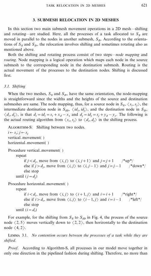
3. SUBMESH RELOCATION IN 2D MESHES
In this section two main submesh movement operations in a 2D mesh��shiftingand rotating��are studied. Here, all the processes of a task allocated to SS aremoved in parallel to the nodes in another submesh, SD . According to the orienta-tions of SS and SD , the relocation involves shifting and sometimes rotating also asmentioned above.
Both the shifting and rotating process consist of two steps��node mapping androuting. Node mapping is a logical operation which maps each node in the sourcesubmesh to the corresponding node in the destination submesh. Routing is theactual movement of the processes to the destination nodes. Shifting is discussedfirst.
3.1. Shifting
When the two meshes, SS and SD , have the same orientation, the node-mappingis straightforward since the widths and the heights of the source and destinationsubmeshes are same. The node mapping, thus, for a source node in SS , (si , sj) , theintermediate destination node in SID , (id i , idj) , and the destination node in SD ,(di , dj) , is that di =idi =si +xd &xs and d j =idj =sj +yd &ys . The following isthe actual routing algorithm from (si , sj) to (di , dj) in the shifting process.
Algorithm-S: Shifting between two nodes.i � si ; j � sj
vertical�movement( )horizental�movement( )
Procedure vertical�movement( )repeat
if j<dj , move from (i, j) to (i, j+1) and j=j+1 �*up*�else if j>dj , move from (i, j) to (i, j&1) and j=j&1 �*down*�else stop
until ( j=dj)
Procedure horizontal�movement( )repeat
if i<di , move from (i, j) to (i+1, j) and i=i+1 �*right*�else if i>di , move from (i, j) to (i&1, j) and i=i&1 �*left*�else stop
until (i=di)
For example, for the shifting from SS to SID in Fig. 4, the process of the sourcenode (2, 5) moves vertically down to (2, 2) , then horizontally to the destinationnode (4, 2).
Lemma 3.1. No contention occurs between the processes of a task while they areshifted.
Proof. According to Algorithm-S, all processes in our model move together inonly one direction in the pipelined fashion during shifting. Therefore, no more than
621TASK RELOCATION IN 2D MESHES
one process need to use the same link at the same time. Certainly, no contentioncan occur.
Lemma 3.2. Shifting can be made either horizontally - first or vertically - first. Ineither case, the routing time for one process is |xs&xd |+| ys&yd | assuming that therouting time for a process from a node to a physically adjacent node is a unit timewhen no contention exists for the link, and it is minimum.
Proof. In shifting, the paths between every source and destination node are theshortest paths. Due to Lemma 3.1, no delay occurs due to contention. Therefore,the routing time is the node distance of the shortest matching corners.
Theorem 3.1. The routing of nodes in Algortihm-S is deadlock free.
Proof. There is no circular wait in the paths because all processes movetogether in only one direction in the pipelined fashion.
Let d be the distance between the two corresponding nodes of SS and SD wherewSS=wSD and hSS=hSD . As a direct consequence of Lemmas 3.1 and 3.2 andTheorem 3.1, it is clear that all processes in SS can be relocated to SD in d timeunits. We next consider the rotating process.
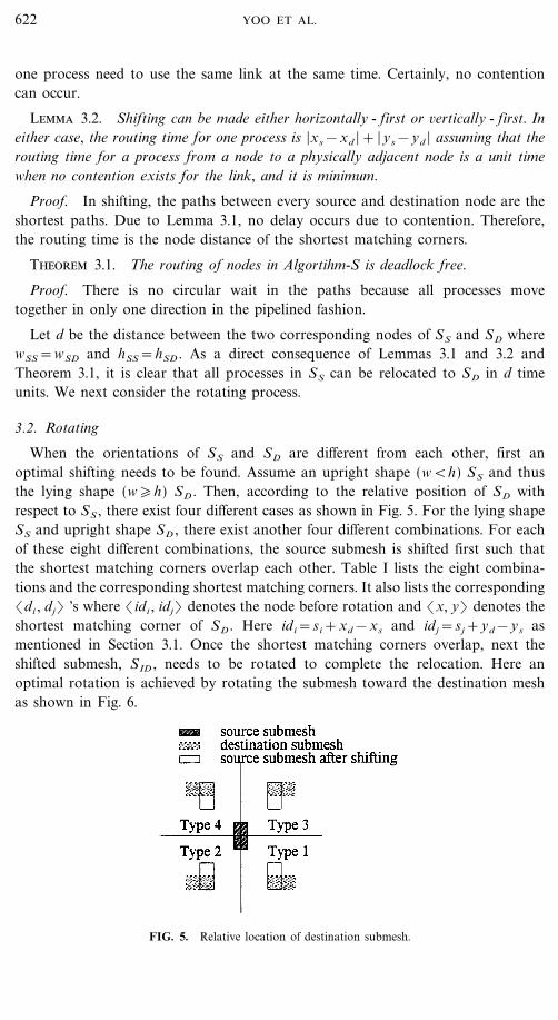
3.2. Rotating
When the orientations of SS and SD are different from each other, first anoptimal shifting needs to be found. Assume an upright shape (w<h) SS and thusthe lying shape (w�h) SD . Then, according to the relative position of SD withrespect to SS , there exist four different cases as shown in Fig. 5. For the lying shapeSS and upright shape SD , there exist another four different combinations. For eachof these eight different combinations, the source submesh is shifted first such thatthe shortest matching corners overlap each other. Table I lists the eight combina-tions and the corresponding shortest matching corners. It also lists the corresponding(di , dj) 's where (idi , idj) denotes the node before rotation and (x, y) denotes theshortest matching corner of SD . Here idi=si+xd&xs and idj=sj+yd&ys asmentioned in Section 3.1. Once the shortest matching corners overlap, next theshifted submesh, SID , needs to be rotated to complete the relocation. Here anoptimal rotation is achieved by rotating the submesh toward the destination meshas shown in Fig. 6.
FIG. 5. Relative location of destination submesh.
622 YOO ET AL.

TABLE I
The Shortest Matching Corners For Eight Different Combinations ofthe Relative Location of SS and S D
Location Shape of The shortestType of SD source task matching corner di dj
1 lr w�h ll x+y+h&1&idj y&x+idi
2 ll w�h lr x&y&h+1+idj x+y&idi
3 ur w�h ul x&y+h&1+idj x+y&idi
4 ul w�h ur x+y&h+1&idj y&x+idi
5 lr w>h ur x&y+idj x+y&w+1&idi
6 ll w>h ul x+y&idj y&x&w+1+idi
7 ur w>h lr x+y&idj y&x+w&1+idi
8 ul w>h ll x&y+idj x+y+w&1&idi
Theorem 3.2. For Type 1 of Table I, a source node (si , sj) is mapped to(di , dj) where di=x+y+h&1&idj and dj=y&x+idi .
Proof. (si , sj) is mapped to (idi , idj) after shifting. Refer to Fig. 7. Since SID
is rotated 90% counter-clockwise, it is easy to see that di=(x+h&1)&(idj&y)=x+y+h&1&idj , and dj=y+(idi&x)=y&x+idi .
Assume SS=(2, 5, 3, 7) and SD=(4, 2, 6, 3) as in Fig. 4. It is Type 1, and thusSID=(4, 2, 5, 4) and (x, y)=(4, 2) . The node-mappings are (2, 5) � (4, 2)from shifting, then (6, 2) from rotating. This is because di=4+2+3&1&2=6and dj=2&4+4=2. (di , dj) for other seven types are obtained by the same way,and they are also listed in Table I.
Now consider an exceptional case shown in Fig. 8. Observe that the shortestmatching corner between SS (2, 1, 3, 7) and SD (4, 4, 10, 5) is ul, which is P inthe figure. In a 2D mesh where no end-around links exist, SS cannot be shifted toSID1 because SID1 is out of bound. In this case, SS is shifted to only one directionto SID2 . Table II lists the adjusted destination nodes of Table I considering this
FIG. 6. Eight rotating types.
623TASK RELOCATION IN 2D MESHES

FIG. 7. Node mapping of Type 1.
condition, where d is the distance of two corresponding shortest matching cornersbetween SS and SID . Note that this exceptional case is irrelevant to a 2D torus.
After the node-mapping, actual routing of each process is done according to thefollowing algorithm.
Algorithm-R: Rotating between two nodes.if (Type=1, 4, 5, or 8)
if (di�si and dj�sj) or (di<si and dj<sj)horizontal�movement( )vertical�movement( )
elsevertical�movement( )horizontal�movement( )
else �* Type=2, 3, 6, or 7 *�if (di �si and dj�sj) or (di<si and dj<sj)
vertical�movement( )horizontal�movement( )
elsehorizontal�movement( )vertical�movement( )
Lemma 3.3. No contention occurs between the processes of a task while they arerotated.
Proof. Here only Type 1 is considered since all eight types are symmetric. Themain property of Algorithm-R is that the nodes in the source submesh move along
FIG. 8. Example of out-of-mesh-bound.
624 YOO ET AL.

TABLE II
Adjustment of Destination Nodes in Table Iin Exceptional Cases
Type di dj
1 x+y+h&1&idj &d y&x+idi &d2 x&y&h+1+idj+d x+y&idi &d3 x&y+h&1+idj &d x+y&idi +d4 x+y&h+1&idj+d y&x+idi+d5 x&y+idj+d x+y&w+1&idi+d6 x+y&idj&d y&x&w+1+idi+d7 x+y&idj+d y&x+w&1+idi &d8 x&y+idj&d x+y+w&1&idi&d
the disjoint paths as shown in Fig. 9. Therefore, no contention can occur. The sameproperty holds for the out-of-bound case as shown in Fig. 10.
Theorem 3.3. All processes in SID can be rotated to SD in max (w&1, h&1)time units.
Proof. In rotating phase, the process movement requiring the longest time isclearly due to the nodes at boundaries. Observe from Fig. 9 that ulSID , which ismapped to llSD , is one of such nodes. Clearly the distance is h&1. Due to Lemma3.3, no contention occurs during rotating, and all processes in Type 1, 2, 3, and 4can be rotated in h&1 (>w&1) time units. Similarly, the maximum rotating timefor Type 5, 6, 7, and 8 is w&1 (>h&1). Therefore, the rotating time is max(w&1, h&1). A similar proof can be applied to the out-of-bound case.
Theorem 3.4. The routing of nodes in Algorithm-R is deadlock free.
Proof. Due to Lemma 3.3, no contention occurs during rotating. Therefore,there is no circular wait in the paths.
We next present the proposed relocation schemes which are based on these twobasic routing processes.
FIG. 9. Routing paths of processes in Type 1.
625TASK RELOCATION IN 2D MESHES

FIG. 10. Routing paths of processes in Type 1 for out-of-bound case.
4. PROPOSED RELOCATION SCHEMES
In this section, two proposed relocation schemes��full and partial reloca-tion��are introduced. Full relocation is the relocation involving all tasks in themesh, and thus it is desirable when the system is highly fragmented. Assume,however, that allocation of an incoming task becomes possible by relocating onlya portion of allocated tasks. In this situation, it may be preferable to relocate onlythose tasks. This is called partial relocation. We first introduce the full relocation.
4.1. Full Relocation
For the task relocation in 2D mesh structures, three steps are involved: they are
(i) submesh-mapping from the source submesh to the destination submesh,
(ii) node-mapping between the nodes in the source submesh and thedestination submesh, and finally
(iii) task movement through the shortest deadlock-free paths. The submeshmapping and node mapping are logical steps for finding the new locations of thepreviously allocated tasks, while the actual task relocation takes place in the finalstep of task movement. For submesh mapping, c-list and r-list are maintained.
Definition 8. c-list is an ordered list which keeps the task id and the x-coor-dinate of the base of the submesh allocated to the task by the increasing order ofx-coordinates. r-list is based on y-coordinate. For example, c-list of Fig. 1 is (1, 1),(2, 5), (3, 8), and r-list is (2, 2), (1, 3), (3, 3) assuming Task 3 was allocated laterthan Task 1. An entry is made and deleted from them at the allocation anddeallocation time, respectively.
The following explains each of the three steps required in the full relocationscheme. In the submesh-mapping step, all tasks are shifted (of course logically) tothe left (bottom) if the height of the incoming task is greater (smaller) than thewidth. Then it is checked if a submesh large enough to accommodate the incomingtask is available. If not, they are shifted to the bottom (left), and then theavailability is checked again. This process is repeated until the desired size submeshis obtained or no more movement can be possible. We call this interleaved rowwise
626 YOO ET AL.

FIG. 11. The allocation of T=(7, 3) after down movement.
and columnwise shift interleaved compaction. For example, in Fig. 1, assume thatT=(4, 7) has arrived. As the height of it is greater than the width, all tasks aremoved left as shown in Fig. 2. c-list now contains (1, 1), (2, 3), (3, 4). After themovements, the system finds a submesh (7, 1, 10, 7) which is large enough toaccommodate T=(4, 7). Instead of T=(4, 7), assume that T=(7, 3) was arrived.Then all tasks are moved down as shown in Fig. 11. r-list is updated as (2, 1),(1, 1), (3, 1). The system can find a submesh (3, 6, 9, 8) large enough to accom-modate T=(7, 3). If the incoming task was T=(7, 5), even with the movements ofFig. 11, the required size submesh is not available yet. Thus all the tasks are thenmoved left as shown in Fig. 12. Now the system finds a submesh (4, 4, 10, 8) . Asmentioned above, these are logical operations for finding the submesh mapping ofeach task.
Now we will show a case in which more than one horizontal and one verticalmovement occur. In Fig. 13 a, assume that T=(10, 2) has arrived. Since no taskcan be initially moved down, left movement is initiated. First, Tasks 3 and 4 aremoved left. Second, only Task 3 is moved down. Third, Task 4 is moved left. Next,Task 4 is moved down. Now the system can find a submesh (1, 7, 10, 8 ) foraccommodating T=(10, 2) as shown in Fig. 13b. Here Tasks 1 and 2 are notmoved. In this example two horizontal and two vertical movements occurred.
FIG. 12. The allocation of T=(7, 5) after left movement.
627TASK RELOCATION IN 2D MESHES

FIG. 13. (a) An allocation of T=(10, 2) before task movement, (b) an allocation of T=(10, 2)after task movement.
Note that only shifting is necessary for full relocation. Therefore, once the sourceand destination submeshes are determined from the submesh mapping step, nodemapping and finally Algorithm-S presented in Section 3 are used for completing therelocation of the submeshes. The following is the procedure of full relocation forincoming task T=(w, h).
PROCEDURE: FULL RELOCATION
v Step 1: �* Step 1�4: Decision of relocatability *�direction=(down, left)list=(c-list, r-list)if w>h
then direction � down and list � r-listelse direction � left and list � c-list
prev-move � true
v Step 2: Move all tasks toward direction using list. If no task has beenmoved, go to Step 4.
v Step 3:Check whether a submesh can be allocatable to the incoming task.
�*use original allocation scheme*�If allocatable
then go to Step 5else prev-move � true, change direction and list, and go to Step 2.
v Step 4:If prev-move is true
then prev-move � false, change direction and list, and go to Step 2else go to Step 6.
v Step 5: Node-mapping; Task movement by shifting; Allocation of thesubmesh to the incoming task. Stop.
v Step 6: No relocation can be made. Stop.
It is intuitively clear that the proposed interleaved compaction scheme always resultsin a larger submesh than either column-wise-only compaction or row-wise-only
628 YOO ET AL.
compaction. The following theorem determines the relocation time of the fullrelocation scheme.
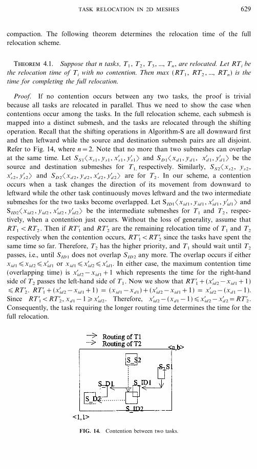
Theorem 4.1. Suppose that n tasks, T1 , T2 , T3 , ..., Tn , are relocated. Let RTi bethe relocation time of Ti with no contention. Then max (RT1 , RT2 , ..., RTn) is thetime for completing the full relocation.
Proof. If no contention occurs between any two tasks, the proof is trivialbecause all tasks are relocated in parallel. Thus we need to show the case whencontentions occur among the tasks. In the full relocation scheme, each submesh ismapped into a distinct submesh, and the tasks are relocated through the shiftingoperation. Recall that the shifting operations in Algorithm-S are all downward firstand then leftward while the source and destination submesh pairs are all disjoint.Refer to Fig. 14, where n=2. Note that no more than two submeshes can overlapat the same time. Let SS1(xs1 , ys1 , x$s1 , y$s1) and SD1(xd 1 , yd 1 , x$d 1 , y$d 1) be thesource and destination submeshes for T1, respectively. Similarly, SS2(xs2 , ys2 ,x$s2 , y$s2) and SD2(xd 2 , yd 2 , x$d 2 , y$d 2) are for T2 . In our scheme, a contentionoccurs when a task changes the direction of its movement from downward toleftward while the other task continuously moves leftward and the two intermediatesubmeshes for the two tasks become overlapped. Let SID1(xid1 , yid1 , x$id1 , y$id1) andSID2(xid2 , yid2 , x$id2 , y$id2) be the intermediate submeshes for T1 and T2 , respec-tively, when a contention just occurs. Without the loss of generality, assume thatRT1 <RT2 . Then if RT $1 and RT $2 are the remaining relocation time of T1 and T2
respectively when the contention occurs, RT $1<RT $2 since the tasks have spent thesame time so far. Therefore, T2 has the higher priority, and T1 should wait until T2
passes, i.e., until SID1 does not overlap SID2 any more. The overlap occurs if eitherxid1�xid2�x$id1 or xid1�x$id2�x$id1. In either case, the maximum contention time(overlapping time) is x$id2&xid1+1 which represents the time for the right-handside of T2 passes the left-hand side of T1 . Now we show that RT $1+(x$id2&xid1+1)�RT $2 . RT $1+(x$id2&xid1+1) = (xid1&xd1)+(x$id2&xid1+1) = x$id2&(xd1&1).Since RT $1<RT $2 , xd1&1�x$id2 . Therefore, x$id2&(xd1&1)�x$id2&x$d 2=RT $2 .Consequently, the task requiring the longer routing time determines the time for thefull relocation.
FIG. 14. Contention between two tasks.
629TASK RELOCATION IN 2D MESHES

FIG. 15. Range of relocation array for T=(4, 7).
4.2. Partial Relocation
In full relocation, all tasks in the mesh are involved. Thus some tasks may berelocated unnecessarily. For example, in Fig. 1, assume that T=(4, 7) has arrived.To find a free submesh for T, full relocation has relocated Task 2 (5 processes) andTask 3 (9 processes) as shown in Fig. 2. However, the system can find a free sub-mesh if only Task 1 is relocated as shown in Fig. 16b. The basic idea of partialrelocation is that tasks are relocated such that the number of processes relocatedis minimized. For this, relocation array is manipulated for finding such submesh.
Definition 9. In a mesh M(a,b), for every incoming task T=(w, h) requiringrelocation of already allocated submesh, SA , a relocation array R is formed.Here, R [i, j] (1�i�a&w+1, 1�j�b&h+1) represents the total number ofprocessors required to be relocated when T is allocated to candidate submeshSC (i, j, i+w&1, j+h&1) .
Refer to Fig. 15, and assume that T=(4, 7) arrives. Observe that the shadedregion denotes the nodes on which the base of the submesh for T can be put. If thetask is allocated to candidate submesh (2, 1, 5, 7) , Task 1 and 2 should berelocated. Therefore, R [2, 1] is 17 because the area of submesh (1, 3, 2, 8) forTask 1 is 12 and the area of submesh (5, 2, 5, 6) for Task 2 is 5. The relocationarray for T is thus as follows.
R=_12 17 5 5 14 9 912 17 5 5 14 9 9&
R is set up as explained below.
PROCEDURE: CONSTRUCT-R
R[i, j] (1�i�a&w+1, 1� j�b&h+1) � 0.For each i
For each jConstruct SC for TFor each SA
630 YOO ET AL.
If SA overlaps with SC
Add area of SA to R[i, j]
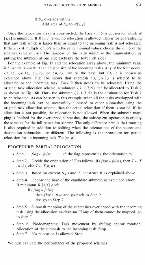
Once the relocation array is constructed, the base (i, j) is chosen for which R[i, j] is minimum. If R [i, j]�wh, no relocation is allowed. This is for guaranteeingthat any task which is larger than or equal to the incoming task is not relocated.If there exist multiple (i, j) 's with the same minimal values, choose the (i, j) of thesmallest value of i+j. The purpose of this is to minimize the fragmentation byputting the submesh at one side (actually the lower left side).
For the example of Fig. 15 and the relocation array above, the minimum valueis 5, which is smaller than 28 (the size of the incoming task). Any of the four nodes,(3, 1) , (4, 1) , (3, 2) , or (4, 2) , can be the base, but (3, 1) is chosen asexplained above. Fig. 16a shows that submesh (3, 1, 6, 7) is selected to beallocated to the incoming task. Task 2 then needs to be relocated. Using theoriginal task allocation scheme, a submesh (7, 1, 7, 5) can be allocated to Task 2as shown in Fig. 16b. Thus, the submesh (7, 1, 7, 5) is the destination for Task 2to be relocated. As can be seen in this example, when all the tasks overlapped withthe incoming task can be successfully allocated to other submeshes using theoriginal task allocation scheme, then the actual relocation of them is started. If theallocation is not possible, the relocation is not allowed. When the submesh map-ping is finished for the overlapped submeshes, the subsequent operation is exactlythe same as for the full relocation scheme. The only difference here is that rotatingis also required in addition to shifting when the orientations of the source anddestination submeshes are different. The following is the procedure for partialrelocation for an incoming task T=(w, h).
PROCEDURE: PARTIAL RELOCATION
v Step 1. flag � false. �* the flag representing the orientation *�
v Step 2. Decide the orientation of T as follows. If ( f lag=false), then T � T(w, h), else T � T(h, w).
v Step 3. Based on current SA 's and T, construct R as explained above.
v Step 4. Choose the base of the candidate submesh as explained above.If minimum R [i, j]�wh
if ( f lag=false)then f lag � true and go back to Step 2else go to Step 7.
v Step 5. Submesh mapping of the submeshes overlapped with the incomingtask using the allocation mechanism. If any of them cannot be mapped, goto Step 7.
v Step 6. Node-mapping; Task movement by shifting and�or rotation;Allocation of the submesh to the incoming task. Stop.
v Step 7. No relocation is allowed. Stop.
We next evaluate the performance of the proposed schemes.
631TASK RELOCATION IN 2D MESHES
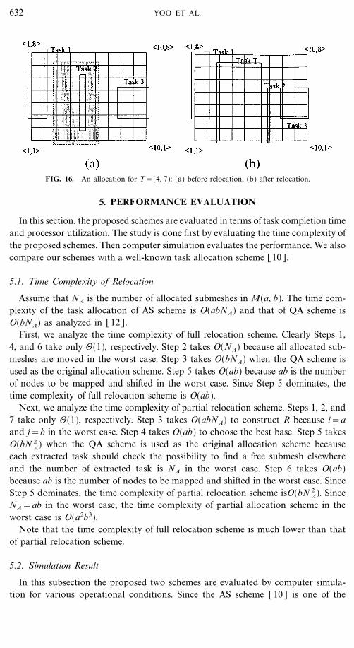
FIG. 16. An allocation for T=(4, 7): (a) before relocation, (b) after relocation.
5. PERFORMANCE EVALUATION
In this section, the proposed schemes are evaluated in terms of task completion timeand processor utilization. The study is done first by evaluating the time complexity ofthe proposed schemes. Then computer simulation evaluates the performance. We alsocompare our schemes with a well-known task allocation scheme [10].
5.1. Time Complexity of Relocation
Assume that NA is the number of allocated submeshes in M(a, b). The time com-plexity of the task allocation of AS scheme is O(abNA) and that of QA scheme isO(bNA) as analyzed in [12].
First, we analyze the time complexity of full relocation scheme. Clearly Steps 1,4, and 6 take only 3(1), respectively. Step 2 takes O(NA) because all allocated sub-meshes are moved in the worst case. Step 3 takes O(bNA) when the QA scheme isused as the original allocation scheme. Step 5 takes O(ab) because ab is the numberof nodes to be mapped and shifted in the worst case. Since Step 5 dominates, thetime complexity of full relocation scheme is O(ab).
Next, we analyze the time complexity of partial relocation scheme. Steps 1, 2, and7 take only 3(1), respectively. Step 3 takes O(abNA) to construct R because i=aand j=b in the worst case. Step 4 takes O(ab) to choose the best base. Step 5 takesO(bN 2
A) when the QA scheme is used as the original allocation scheme becauseeach extracted task should check the possibility to find a free submesh elsewhereand the number of extracted task is NA in the worst case. Step 6 takes O(ab)because ab is the number of nodes to be mapped and shifted in the worst case. SinceStep 5 dominates, the time complexity of partial relocation scheme isO(bN 2
A). SinceNA=ab in the worst case, the time complexity of partial allocation scheme in theworst case is O(a2b3).
Note that the time complexity of full relocation scheme is much lower than thatof partial relocation scheme.
5.2. Simulation Result
In this subsection the proposed two schemes are evaluated by computer simula-tion for various operational conditions. Since the AS scheme [10] is one of the
632 YOO ET AL.
most efficient allocation schemes, it is employed as the allocation scheme. Simula-tions are conducted for the meshes ranging from 4_4 to 64_64. All the simulationuse 950 confidence level with an error range of \30. The simulator wasdeveloped in C language running on a Sun 4�490. Two different relocation schemesare studied; the full relocation scheme with the parallel task-relocation (FR-p) andthe partial relocation scheme with the sequential task-relocation (PR-s). Noticethat, due to the possibility of contention, sequential movement is assumed for thepartial relocation.
The time for a task relocation [14] consists of the time for message startup,suspending�resuming the tasks, synchronization, forwarding in-transit messages,and context switch. The time for suspending�resuming a task and context switchis negligible compared to the time for actual task relocation. The relocation time isthus determined by the routing time from the original to the new sites which isobtained by multiplying the routing distance and the time for one position movement.As mentioned earlier, the time for one position movement is machine dependent,which is obtained by the product of the relocation overhead factor (:) and theresidence time. The performance of our relocation schemes is evaluated for severaldifferent values of : as others do [14]. The relocation time is added to the taskservice time (residence time) when the overall performance is evaluated. The reloca-tion may result in the increase of the performance by decreasing the externalfragmentation, or degradation because of the excessive relocation overhead.
We employ the same simulation model used in [8, 10, 12, 14, 15]. Task alloca-tion is carried out by a separate processor which functions as a task dispatcher.Initially the entire mesh is free, and 1000 tasks are generated and queued at the taskdispatcher. Each task has a residence time requirement, which is assumed to beuniformly distributed between 5 to 10 time units. The tasks are assumed to arriveat each time unit. The time unit is large enough such that the time needed for taskdispatcher to scan the whole mesh plane is negligible. The side lengths (width orheight) of incoming tasks are assumed to follow one of the four distributions:uniform, exponential, decreasing, and increasing. For the uniform distribution, theside lengths of incoming tasks are uniformly distributed between 1 and the sidelength of the mesh (L). For the exponential distribution, the mean is selected as thehalf of L. Those values outside the range [1, side length+1) were discarded. Forthe decreasing distribution, the probability that a side length of an incoming taskfalls into the range [1, L�8] is 0.4, [L�8+1, L�4] is 0.2, [L�4+1, L�2] is 0.2, and[L�2+1, L] is 0.2. For example, the probability that a side length falling into therange [s1 , s2] of M(16, 16), denoted as P[s1, s2] is distributed as follows; P[1, 2]=0.4, P[3, 4]=0.2, P[5, 8]=0.2, and P[9, 16]=0.2. For the increasing distribution, thedistributions are the opposite of the decreasing distribution. For M(16, 16), again,P[1, 8]=0.2, P[9, 12]=0.2, P[13, 14]=0.2, and P[15, 16]=0.4. The widths and heightsof tasks are generated separately based on the above distributions.
The task dispatcher is assumed to follow the First-Come-First-Serve (FCFS)discipline, i.e., the dispatcher always tries to find a free submesh for the first taskin the queue. If it fails to find a free submesh, the dispatcher simply waits for asubmesh to be released to allow the allocation. After a task is assigned to asubmesh, it is removed from the queue and the next task in the queue is served in
633TASK RELOCATION IN 2D MESHES

the next time unit. Simulation is done for various values of : from 0.01 to 0.05. Forevery relocation, the routing time between the two submeshes is computed. Thenthe relocation time, the routing time multiplied by :, is added to the remainingresidence time of the task.
We collect the following five performance metrics: (i) the allocation completiontime (Tc), (ii) the average processor utilization over Tc , (iii) the number of reloca-tions done, (iv) average number of tasks relocated per relocation occurred, and(v) average size of relocated task in terms of the number of processors. Table IIIcompares the proposed relocation schemes and AS scheme under various valuesof :. Note that := 0 for AS scheme since it does not involve any relocation. Fromit, we observe the following.
v FR-p outperforms AS scheme (no relocation) when :�0.03. It means thatthe relocation schemes are effective only for smaller relocation overhead factors.
TABLE III
Performance Comparisons under Various Values of : of M (16, 16)Scheduling: FCFS, T=1000
Side length Performance:
distribution measure Scheme 0 0.01 0.02 0.03 0.04 0.05
Uniform Task AS 3482completion FR-p 3365 3394 3421 3449 3476
time PR-s 3343 3410 3504 3584 3625
Processor AS 61.36utilization FR-p 63.39 62.85 62.35 61.85 61.36
( 0) PR-s 63.81 62.56 60.97 59.62 58.85
Exponential Task AS 1740completion FR-p 1652 1688 1719 1749 1782
time PR-s 1650 1767 1905 2095 2254
Processor AS 60.90utilization FR-p 64.11 62.75 61.64 60.58 59.45
( 0) PR-s 64.19 59.96 55.63 50.59 46.99
Decreasing Task AS 1235completion FR-p 1163 1192 1226 1250 1287
time PR-s 1174 1352 1561 1749 2003
Processor AS 60.49utilization FR-p 64.23 62.70 60.93 59.75 58.09
( 0) PR-s 63.65 55.25 47.88 42.74 37.31
Increasing Task AS 5899completion FR-p 5855 5867 5879 5891 5903
time PR-s 5851 5867 5882 5898 5914
Processor AS 69.91utilization FR-p 70.44 70.30 70.15 70.01 69.87
( 0) PR-s 70.48 70.29 70.11 69.92 69.73
Note. Residence time distribution: Uniform [5, 10].
634 YOO ET AL.

v Among the four distributions, the decreasing distribution is the mostsensitive to the value of :, and the increasing distribution is the least.
v Compared to the full relocation scheme, the partial relocation scheme per-forms worse if :>0.01. This is because the relocation overhead is more significantthan the reduced number of process relocation.
From Table IV, which studies the schemes for various size meshes when :=0.01,we observe the following.
v Our relocation schemes are relatively more effective for smaller size meshes.Notice that the performance difference between ours and AS scheme gets smaller asthe size of mesh increases.
v The full relocation scheme outperforms the partial relocation scheme forrelatively large meshes. This is because the relocation distance of partial relocationis longer than that of full relocation in the worst case.
TABLE IVPerformance Comparisons for Various Sizes When :=0.01
Scheduling: FCFS, T=1000
Side length PerformanceMesh size
distribution measure Scheme 4_4 8_8 16_16 32_32 64_64
Uniform Task AS 3987 3625 3482 3358 3356completion FR-p 3940 3530 3365 3336 3288
time PR-s 3892 3467 3343 3343 3378
Processor AS 73.49 65.59 61.36 58.96 58.21utilization FR-p 74.5 67.09 63.39 59.95 59.00
( 0) PR-s 75.42 68.31 63.81 59.83 57.42
Number of FR-p 30 54 70 76 79recolation occured PR-s 55 90 96 102 106
Number of FR-p 1.16 1.35 1.39 1.39 1.50tasks relocated PR-s 1.05 1.15 1.20 1.20 1.21
Size of tasks FR-p 3.85 12.65 45.48 178.61 701.95relocated PR-s 2.58 7.90 27.53 110.73 391.04
Exponential Task AS 2291 1864 1775 1677 1626completion FR-p 2207 1774 1652 1610 1638
time PR-s 2137 1700 1650 1692 1961
Processor AS 74.66 66.20 60.67 57.58 56.13utilization FR-p 77.48 69.55 64.11 59.97 55.73
( 0) PR-s 80.03 72.57 64.19 57.03 46.55
Number of FR-p 67 93 103 113 122relocations occured PR-s 135 177 171 174 187
Number of FR-p 1.61 2.04 2.31 2.49 2.82task relocated PR-s 1.15 1.35 1.40 1.51 1.51
Size of tasks FR-p 2.65 7.84 28.61 109.55 401.08relocated PR-s 1.86 4.77 16.64 61.97 233.22
Note. Residence time distrubution: Uniform [5, 10].
635TASK RELOCATION IN 2D MESHES

v FR-p requires fewer relocations than PR-s. This is expected since the partialrelocation scheme does not fully compact the array.
v As expected the average number of relocated tasks per relocation and the sizeof tasks relocated of partial relocation are much smaller than that of full relocation.
To check the effect of the side lengths in the two relocation schemes, we havesimulated two more cases. In the first case, all requests are squares whose sidelengths are power of two and uniformly distributed. For example, in M(16, 16), sidelength is 1, 2, 4, 8, or 16, and those five numbers are uniformly distributed. In thesecond case, all requests are rectangles whose side lengths are power of two andalso uniformly distributed. The other conditions are same as the previous simula-tions. However, in these two cases, we do not observe any particular difference fromthe above-mentioned observations.
In addition, another simulation is conducted in order to study the externalfragmentation. The simulation results for mesh systems of various sizes follow asimilar trend, and thus we report the simulation results for only the 16_16 meshsystem. The simulation uses a 900 confidence level with an error range of \50.Task residence time and interarrival time are assumed to have the exponentialdistribution with the means of MTRT (mean task residence time) and MIAT (meantask interarrival time), respectively. Here system load is defined as (n_MTRT)�(N_MIAT) where n is the average size of the requested submesh in terms of thenumber of processors and N is the total number of processors in the 2D meshsystem. In the simulation, we fix MTRT to be 7.5 time units and adjust MIATaccording to the desired load.
Figure 17 plots the external fragmentation of the studied relocation schemesunder different workloads of M(16, 16) when :=0.01 for exponential distributionof side lengths. We observe the following from the simulation result.
v Regardless of the system load, both relocation schemes decrease the externalfragmentation. For example, under the system load of 0.5, the external fragmentation
FIG. 17. External fragmentation versus offered system load.
636 YOO ET AL.

without relocation is 50.20, whereas those under the full relocation and the partialrelocation are 45.80 and 43.40, respectively.
v As expected, the partial relocation scheme decreases the external fragmenta-tion more than the full relocation scheme. This agrees with the information inTable IV, where the number of relocations occurred in the partial relocationscheme is much higher than that in the full relocation scheme.
6. CONCLUSION
In this paper, we have presented two relocation schemes��full relocation andpartial relocation��for enhancing the performance of 2D mesh architecture byreducing external fragmentation. The partial relocation scheme tries to minimize therelocated tasks while the full relocation scheme involves simple shift operations ofall tasks. For general relocation processes, we also developed and modeled twobasic submesh relocation operations��shifting and rotating. Simulation resultsshow that both schemes increase the performance of the system in terms of taskcompletion time and system utilization up to a certain value of relocation overheadfactor which is machine dependent. The full relocation scheme demonstrated betterperformance than the partial relocation scheme for relatively large meshes andrelocation overhead. The relocation scheme is also useful when high�priority jobsarrive but are not allocatable in a real-time environment. The performance of amesh system is expected to be further enhanced if every task allocation is deter-mined such that the external fragmentation is less likely. This issue is currentlybeing investigated.
REFERENCES
1. P. Muzumdar, Evaluation of on-chip static interconnection networks, IEEE Trans. Comput. 36(March 1987), 365�369.
2. G. Randade and S. L. Johnsson, The communication efficiency of meshes, boolean cubes andcube connected cycles for wafer scale integration, in ``Proc. of the International Conf. on ParallelProcessing,'' pp. 477�482, Aug. 1987.
3. ``Paragon XP�S Product Overview,'' Intel Corporation, 1991.
4. ``A Touchstone DELTA System Description,'' Intel Corporation, 1991.
5. J. Kim, C. R. Das, and W. Lin, A top-down processor allocation scheme for hypercube computers,IEEE Trans. Parallel Distrib. Systems 2 (Jan. 1991), 21�30.
6. P. J. Chuang and N. F. Tzeng, A fast recognition-complete processor allocation strategy forhypercube computers, IEEE Trans. Comput 41, 4 (April 1992), 467�479.
7. K. Li and K. H. Cheng, A two-dimensional buddy system for dynamic resource allocation in apartitionable mesh connected system, J. Parallel Distrib. Comput. 12 (May 1991), 79�83.
8. P. J. Chuang and N. F. Tzeng, An efficient submesh allocation strategy for mesh computer systems,in ``Proc. of the International Conf. on Distributed Computing Systems,'' pp. 256�263, Aug. 1991.
9. Y. Zhu, Efficient processor allocation strategies for mesh-connected parallel computers, J. ParallelDistrib. Comput. 16 (Dec. 1992), 328�337.
10. J. Ding and L. N. Bhuyan, An adaptive submesh allocation strategy for two-dimensional meshconnected systems, in ``Int'l Conf. on Parallel Processing,'' pp. II-193�200, Aug. 1993.
637TASK RELOCATION IN 2D MESHES
11. D. D. Sharma and D. K. Pradhan, Job scheduling in mesh multicomputers, IEEE Trans. ParallelDistrib. Systems (Jan. 1998), 57�70.
12. S. M. Yoo, H. Y. Youn, and B. Shirazi, An efficient task allocation scheme for 2D mesh architectures,IEEE Trans. Parallel Distrib. Systems (Sep. 1997), 934�942.
13. V. Lo, K. J. Wndish, W. Liu, and B. Nitzberg, Non-contiguous processor allocation algorithms formesh-connected multicomputers, IEEE Trans. Parallel Distrib. Systems (July 1997), 712�726.
14. C. H. Huang and J. Y. Juang, A Partial compaction scheme for processor allocation in hypercubemultiprocessors, in ``Int'l Conf. on Parallel Processing,'' pp. I-211�217, 1990.
15. M. S. Chan and K. G. Shin, Subcube allocation and task migration in hypercube multiprocessors,IEEE Trans. Comput. 39, 9 (Sep. 1990), 1146�1155.
16. K. Hwang and H. Xu, ``Scalable Parallel Computing: Technology, Architecture, Programming,''WCB�McGraw�Hill, Boston, 1998.
SEONG-MOO YOO received the B.A. in economics from Seoul National University, Seoul, Korea,and the M.S. and Ph.D. in computer science from The University of Texas at Arlington in 1989 and1995, respectively. He is currently an assistant professor in the Department of Computer Science,Columbus State University, Columbus, Georgia. His research interests include parallel computing,multiprocessor systems, computer security, and mobile computing. Dr. Yoo is a member of the Associa-tion for Computing Machinery and the IEEE Computer Society.
HYUNSEUNG CHOO received the B.S. in mathematics from Sungkyunkwan University, Suwon,Korea in 1988, the M.S. in computer science from the University of Texas at Dallas, Richardson, TXin 1990, and the Ph.D. in computer science from the University of Texas at Arlington (UTA), Arlington,TX in 1996. In 1997, he was a faculty associate of the Department of Computer Science and Engineeringat UTA. From 1997 to 1998, he was a patent examiner at Korean Industrial Property Office, Seoul,Korea. Dr. Choo is currently an assistant professor of the School of Electrical and Computer Engineer-ing at Sungkyunkwan University, Suwon, Korea. His research interests include networking, ATMswitching, system performance evaluation, parallel and distributed computing, and design of algorithms.
HEE YONG YOUN received the B.S. and M.S. in electrical engineering from Seoul National Univer-sity, Seoul, Korea, in 1977 and 1979, respectively, and the Ph.D. in computer engineering from theUniversity of Massachusetts at Amherst, in 1988. From 1979 to 1984, he was on the research staff ofGold Star Precision Central Research Laboratories, Korea. He is an associate professor in the Depart-ment of Computer Science and Engineering, The University of Texas at Arlington, Arlington, Texas. Heis currently on a leave of absence to Information and Communications University, Korea. He receivedthe Outstanding Paper Award from the 1988 International Conference on Distributed ComputingSystems and 1992 Supercomputing, respectively. He also served as a lecturer of the ACM LectureshipSeries from 1993 to 1997. His research interests include parallel and distributed computing, mobile com-puting, performance modeling and evaluation, and fault-tolerant computing. Dr. Youn is a senior mem-ber of the IEEE Computer Society.
CHANSU YU received the B.S. and M.S. in electrical engineering from Seoul National University,Seoul, Korea in 1982 and in 1984, respectively. He worked as a research engineer at GoldStar Companyuntil 1989. He received the Ph.D. in computer engineering from the Pennsylvania State University in1994. Since 1997, he has been an assistant professor with the School of Engineering, Information andCommunications University, Taejon, Korea. His areas of interest are computer architecture, parallel andcluster computing, performance evaluation, and mobile systems. Dr. Yu is a member of the IEEE andIEEE Computer Society.
YOUNGHEE LEE received B.S. and M.S. in electronics from Seoul National University, Korea, in1976 and 1980, respectively and Ph.D. in computer science from Universite� de Technologie deCompiegne, France in 1984. Since he joined Electronics and Telecommunications Research Institute(ETRI), Korea in 1984, he has been working on the fields of high speed networks, CCS systems, ATM,gigabit networks, and next generation Internet. He is currently Professor of Information andCommunications University in Korea. He also serves as one of the vice chairmen of SG 7 in ITU-T. Hisresearch interests include parallel processing, next generation Internet technologies, and high-speednetworks.
638 YOO ET AL.