on-load tap-changers type vuc user's guide · 2.1 general the on-load tap-changers...
TRANSCRIPT

— 1ZSC0 0 0562- ABE EN, RE V. 2
On-load tap-changers type VUCUser's guide

— Original instructionThe information provided in this document is intended to be general and does not cover all possible applications. Any specific application not covered should be referred directly to ABB, or its authorized representative.
We reserve the right to make technical changes or modify the contents of this document without prior notice. With regard to purchase orders, the agreed particulars shall prevail. ABB does not accept any responsibility whatsoever for potential errors or possible lack of information in this document.
We reserve all rights in this document and in the subject matter and illustrations contained therein. Any reproduction, disclosure to third parties or utilization of its contents – in whole or in parts – is forbidden without prior written consent of ABB.

— Table of contents
1. Safety 51.1 General 51.2 Safety warnings 51.3 Safety precautions 5
1.3.1 Personal safety 51.3.2 Environmental safety 51.3.3 First aid 5
1.3.4 In the event of fire 5
2. Introduction 62.1 General 62.2 Functional description 62.3 Switching sequence, VUCG 72.4 Switching sequence, VUCL 92.5 System overview 122.5.1 Types of switching 132.5.2 Type of connection 142.6 Diverter switches 152.7 Tap selectors 152.8 Design differences across theVUC range of on-load tap-changers 162.9 Contacts 162.10 Vacuum interrupters 162.11 Transition resistors 162.12 Spring-loaded mechanism 162.13 Motor-drive mechanism 162.14 Accessories and protection devices 162.15 Rating plate 18
3. Commissioning 193.1 General 193.2 Reassembly 193.3 Required tools and materials 193.4 Tightening torques 203.5 Oil filling 20
3.5.1 Oil quality 203.5.2 Filling methods and restrictions 203.5.3 Correct oil level 203.5.4 Filling at atmospheric pressure 203.5.5 Filling under vacuum 21
3.6 Mounting of external drive shafts 223.6.1 Mounting of horizontal drive shaft 223.6.2 Mounting of vertical drive shaft 25
3.7 Testing 303.8 Energizing 313.9 Putting into operation 31
4. Operation 324.1 Synchronization between tap-changerand motor-drive mechanism 32
5. Inspection 335.1 General 335.2 Inspection 335.3 Oil sampling 34
5.3.1 Conservator 345.3.2 Sampling procedure fortap-changers 355.3.3 Information about the sample 35
5.4 Maintenance 355.5 Replacement of the complete switchingmechanism including vacuum interrupters 35
6. Electrical diagrams 366.1 Standard circuit diagram BUE 366.2 Contact timing diagram BUE 376.3 Standard circuit diagram BUL2 386.4 Contact timing diagram BUL2 39
7. Technical data 407.1 Dimensions 407.2 Weights 407.3 Specification of materials 40
7.3.1 General 407.3.2 Diverter switch housing 407.3.3 Diverter switch 407.3.4 Tap selector 407.3.5 Conductors 407.3.6 Gearing mechanism 407.3.7 Drive shaft systems 40


O N - LOA D TA P - CH A N G E R S T Y PE V U C USER ' S G U I D E 5
—1. Safety
1.1 GeneralThis user‘s guide must be read and understood, and followed at all times.
1.2 Safety warningsThe following warnings and notes are used in the manual:
WARNING
WARNING indicates an imminently hazardous situation which if not avoided, will result in death or serious injury. This signal word is to be limited to the most extreme situations.
WARNING also indicates a potentially hazardous situation which if not avoided, could result in death or serious injury.
CAUTION
CAUTION indicates a potentially hazardous situation which if not avoided, may result in minor or moderate injury. It may also be used to alert against unsafe practices.
CAUTION may also indicate property-damage-only hazards.
INFO provides additional information to assist in carrying out the work described and to provide trouble-free operation.
1.3 Safety precautions1.3.1 Personal safetyUnused transformer oil is somewhat harmful. Fumes from unused warm oil may irritate the respiratory organs and the eyes. After long and repeated contact with transformer oil, the skin becomes very dry. Avoid contact with the oil as much as possible and use oil-tight protective gloves when handling the oil.
Used tap-changer oil contains harmful substances. Fumes are irritating to the respiratory organs and the eyes and very easily catch fire. Used transformer oil may be carcinogenic.
1.3.2 Environmental safetyCollect used oil in oil drums.
An absorbing agent should be used when cleaning up waste oil. Treat waste oil as hazardous to the environment.
1.3.3 First aid
Skin contact1. Wash the body part that has been exposed to the oil.2. Rub moisturizer into the skin to counteract drying.
In the eyesRinse the eyes with clean water.
Swallowing
WARNING
Avoid vomiting.
1. Drink water or milk. 2. Call a doctor.
1.3.4 In the event of fireIn the event of fire, extinguish with a powder, foam or carbon acid extinguishing agent.

6 O N - LOA D TA P - CH A N G E R S T Y PE V U C USER ' S G U I D E
2.1 GeneralThe on-load tap-changers manufactured by ABB have been developed over a period of many years to provide maximum reliability. In most applications, the simple and robust design provides a service life equal to the service life of the transformer.
Minimum maintenance is required for trouble-free operation. Maintenance is normally not required on the parts situated in the oil of the transformer tank. The only parts requiring maintenance are parts of the diverter switch, the insulating oil and the motor-drive mechanism.
WARNING
Small amounts of explosive gases are constantly discharged from the breathing devices (dehydrating breather or one-way breather). Make sure that no open fires, hot surfaces or sparks are present in the immediate surroundings of the breathing devices.
Personnel operating and inspecting the tap-changer must have good knowledge of the apparatus and be aware of the risks pointed out in this manual.
Personnel making electrical connections in the motor-drive mechanism must be certified for such work.
CAUTION
After a pressure relay trip, contact ABB. The tap-changer housing must be drained and the diverter switch lifted and carefully examined before the transformer is reenergized.
2.2 Functional descriptionThe on-load tap-changer is a device for changing the tapping connection of a winding while the transformer is under load. The main purpose is to maintain a constant voltage out from the transformer and to compensate for variations in the load situation. The tap-changer is connected to the transformer via the tap winding. The main function is tap selection, which is accomplished by changing the number of turns on the regulating winding.
Although numerous different circuit solutions are available, the selected solution has been found to offer the best combination of technical performance and potential for economic operation. By using auxiliary contacts in combination with vacuum interrupters, the contacts are used for carrying current and the vacuum interrupters are used for energized switching.
The electrical circuit principle for the VUCG is shown in Figs. 1-8, and for VUCL in Figs. 9-20. The purpose of the operation is to commute the load from one tap to the other in order to change the voltage.
The figures on the following pages show the contact sequence along with the physical position of the interrupter.
—2. Introduction

O N - LOA D TA P - CH A N G E R S T Y PE V U C USER ' S G U I D E 7
2.3 Switching sequence, VUCGBy using an auxiliary contact system (MC, RC) in combination with the vacuum interrupters (MVI, RVI) only two vacuum interrupters are required per phase.
Fig. 1 shows the current path during normal operation, from x to the star point (could also be to the next phase).
When commuting the load from x to v, the first part of the operation sequence is to open the main vacuum interrupter (MVI) and hence let the current flow through the transition resistor (TR), Fig. 2.
The main contact (MC) is then rotated (Figs. 3 and 4) in order to connect to v.
RVITR
RC
v
MVI
MC
v
MVI
MC
v
MVI
MC
v
—01
—02
—03
—04

8 O N - LOA D TA P - CH A N G E R S T Y PE V U C USER ' S G U I D E
The main vacuum interrupter then closes, leading to an associated circulating current driven by the difference in voltage potential, Fig. 5. The load current is now via the normal path from v to the star point.
In Fig. 6, the transition resistor is disconnected when opening the resistor vacuum interrupters (RVI).
The resistor contact (RC) is then rotated and put in position according to Fig. 7.
Finally, the sequence is completed and next service position is reached when the resistor vacuum interrupter is closed, see Fig. 8.
MC RC
RVITR
RC
x
RVITR
RC
x
RVITR
RC
x
—05
—06
—07
—08

O N - LOA D TA P - CH A N G E R S T Y PE V U C USER ' S G U I D E 9
2.4 Switching sequence, VUCLBy using an auxiliary contact system (MC, RC) in combination with the vacuum interrupters (MVI, RVI) only two vacuum interrupters are required per phase.
Fig. 9 shows the current path during normal operation, from x to the star point (could also be to the next phase).
When commuting the load from x to v, the first part of the operation sequence is to open the bypass contact (BPC), Figs. 10 and 11.
Next is to open the main vacuum interrupter (MVI) and hence let the current flow through the transition resistor (TR), Fig. 12.
MVI
MC
RVITR
RCBPC
x
v
MVI
MC
RVITR
RCBPC
x
v
MVI
MC
RVITR
RCBPC
x
v
MVI
MC
RVITR
RCBPC
x
v
—12
—10
—11
—09

10 O N - LOA D TA P - CH A N G E R S T Y PE V U C USER ' S G U I D E
The main contact (MC) is then rotated (Figs. 13 and 14) in order to connect to v.
The main vacuum interrupter then closes, leading to an associated circulating current driven by the difference in voltage potential, Fig. 15.
The load current now goes from v. The bypass contact is then connected to v (Figs. 16 and 17).
MVI
MC
RVITR
RCBPC
x
v
MVI
MC
RVITR
RCBPC
x
v
MVI
MC
RVITR
RCBPC
x
v
MVI
MC
RVITR
RCBPC
x
v
—13
—16
—15
—14

O N - LOA D TA P - CH A N G E R S T Y PE V U C USER ' S G U I D E 11
MVI
MC
RVITR
RCBPC
x
v
MVI
MC
RVITR
RCBPC
x
v
MVI
MC
RVITR
RCBPC
x
v
MC
RVITR
RCBPC
x
v
MVI
—18
—17
—20
—19
In Fig. 18, the transition resistor is disconnected when opening the resistor vacuum interrupters (RVI).
The load current is now via the normal path from v to the star point. The resistor contact (RC) is then rotated (Fig. 19) and makes the v-side.
Finally, the sequence is completed and next service position is reached when the resistor vacuum interrupter is closed, see Fig. 20.

12 O N - LOA D TA P - CH A N G E R S T Y PE V U C USER ' S G U I D E
2.5 System overviewThe implementation of vacuum technology improves breaking capacity, increases contact life and reduces maintenance.
The design allows easy access to the function control for the switching sequence.
The VUC tap-changers are of the in-tank design. The motor-drive mechanism is attached to the transformer tank and connected to the tap-changer by means of drive shafts and a bevel gear. The motor-drive mechanism is not described in this manual.
The tap-changer is mainly comprised of a housing, a mechanical drive system, a change-over selector and a selector switch.
The tap-changer is designed so that it is suitable for both cover mounting and yoke-mounting (pre-mounting on the transformer’s active part).
Cover-mounting means that the tap-changer is lowered through a hole in the transformer cover and then bolted straight onto the transformer cover. See Fig. 21.
Yoke-mounting means that the tap-changer is temporarily placed on a fork located on the active part of the transformer. See Fig. 22. The transformer cover is then lowered onto the tank, and the tap-changer is lifted and bolted to the cover. Yoke-mounting allows the transformer manufacturer to connect the windings to the tap-changer before drying and without having the transformer cover mounted.
The tap-changers type VUC can be switched using:• Linear switching, see Fig. 23.• Plus/minus switching, see Fig. 24.• Coarse/fine switching, see Fig. 25.
The general arrangement of a tap-changer system can be executed using:• Three-phase, star point connection, see Fig. 26.• Single-phase, see Fig. 27.• Three-phase delta, see Fig. 28.• Three-phase delta, fully insulated connection, see Fig. 29.• Auto transformer, see Fig. 30.
Transformer active part
Yoke fork
On-load tap-changer
Bevel gear
—21 Cover-mounting.
—22 Yoke-mounting.

O N - LOA D TA P - CH A N G E R S T Y PE V U C USER ' S G U I D E 13
Change-over selector, coarse/fine
—24 Change-over selector for plus/minus switching (type R).
—23 Linear switching (type L).
—25 Change-over selector for coarse/fine switching (type D).
2.5.1 Types of switchingLinear switching (type L)With linear switching, the regulating range is equal to the voltage of the tapped winding. No change-over selector is used.
Plus/minus switching (type R)With plus/minus switching, the change-over selector extends the regulating range to twice the voltage of the tapped winding by connecting the main winding to different ends of the regulating winding.
Coarse/fine switching (type D)With coarse/fine switching, the change-over selector extends the regulating range to twice the voltage of the tapped winding by connecting or disconnecting the coarse regulating winding.

14 O N - LOA D TA P - CH A N G E R S T Y PE V U C USER ' S G U I D E
—26 Three-phase neutral point (N).
—27 Single-phase (E).
—28 Three-phase delta (B).
—29 Three-phase fully insulated, delta (T).
—30 Auto transformer (T).
2.5.2 Type of connectionThree-phase star point (N)Only one unit is required for all three phases. The transformers neutral point is in the tap-changer.
Single-phase (E)Only one unit is required.
Three-phase delta (B)Two units required. Driven by a common motor-drive. One unit common for two phases.
Three-phase delta fully insulated (T)Three units required. Driven by a common motor-drive.
Auto transformer (T)Several configurations of auto transformers exist. This example shows the tap-changer in auto-tap.

O N - LOA D TA P - CH A N G E R S T Y PE V U C USER ' S G U I D E 15
2.6 Diverter switchesThe diverter switches with vacuum interrupters are of the high-speed, spring-operated type with resistors as transition impedance. They are equipped with plug-in contacts that automatically connect to the bushings in the diverter switch housing when the switch is lowered into the housing. Guiding facilities keep the diverter switch in the correct position when lowering it into the housing. Mechanical coupling to the motor-drive mechanism is automatically established when the driving pin enters the slot in the driving disc.
The design and dimensioning of the diverter switches offer high reliability and long life with a minimum of maintenance and easy inspection.
Diverter switches with vacuum interrupters combine all the advantages of the conventional type with improved breaking capacity, increased contact life and reduced maintenance.
The switch works according to the pennant cycle, which gives the lowest complexity and allows full power flow in both directions. A mechanical rectifier ensures operation in only the direction that gives the lowest breaking stresses and contact wear, independently of RAISE or LOWER command.
The load is commutated from one tap to the other with the aid of the vacuum interrupters and auxiliary contacts. The auxiliary contacts are also able to break the load current in the unlikely event that a vacuum interrupter failure should occur. For VUCG in service position, the load current is transferred through the auxiliary contacts and the vacuum interrupters. All current carrying contacts are made of low resistance material. For VUCL in service position, the load current is transferred through a bypass contact.
The contact system is operated by a compact mechanical system with integrated driving springs, mechanical rectifier, robust mechanical system for vacuum interrupter actuating and geneva gears for operating the auxiliary contacts.
Most manufactured conventional UCG and UCL diverter switches can be easily replaced by the vacuum diverter switch and gain benefit from the improvements made on this type. The VUCG diverter switch fits in all UCG tap-changers as manufactured 1977 and later without modification, which enables all UCG tap-changers to be easily upgraded to vacuum technology. The VUCL diverter switch fits all UCL housings manufactured 1985 and later without modification.
2.7 Tap selectorsAlthough the tap selector for the VUC range of tap-changer is available in various sizes, all of them have similar functions with different ratings.
The fixed contacts are mounted around the central shafts. The moving contacts are mounted on, and are operated by, the shafts in the center of the selector. The moving contacts are connected, via current collectors, to the diverter switch by means of paper insulated copper conductors.
Depending on the load current, the moving contacts have either one, two, or more contact arms in parallel with one, two or four contact fingers each. The fingers make contact at one end with the fixed contact, and at the other with the current collector. The moving contacts slide on the fixed contacts and the current collector rings, giving a wiping action which makes the contacts self cleaning. This arrangement promotes good conductivity and negligible contact wear.
The tap selectors available for the VUC range of tap-changers are C, III and F. Tap selector C can be combined with VUCG diverter switches. Tap selector III and F can be combined with both VUCG and VUCL. All three tap selector types use a complete, un-divided glass fiber reinforced epoxy cylinder for the fine selector.
16 O N - LOA D TA P - CH A N G E R S T Y PE V U C USER ' S G U I D E
2.12 Spring-loaded mechanismThe spring-loaded mechanism ensures a fast and complete switching sequence even if the power supply fails.
The mechanism is normally operated by the motor-drive unit, but can also be hand-cranked by an operator.
The motor-drive mechanism and bevel gear are mounted on the transformer tank, and the drive shafts are mounted to complete the assembly of the motor-drive mechanism, bevel gear and tap-changer before oil filling and testing.
2.13 Motor-drive mechanismThe bevel gear, mounted on the cover, transfers the motion of the motor-drive mechanism, via the drive shafts, to the tap-changer’s spring-loaded mechanism.
The motor-drive mechanism provides the force for operating the tap-changer. Energy is provided from a motor through a series of gears and out through a drive shaft. Several features are incorporated within the mechanism to lengthen service intervals and improve reliability.
2.14 Accessories and protection devicesThe tap-changer can be equipped with various protection devices. The standard protection device is the pressure relay. An oil flow relay is also available.
A pressure relief device with an alarm signal is also available, as well as certain other supervisory sensors.
For more information about accessories and protection devices, see the technical description 1ZSC000562-AAD.
2.8 Design differences across the VUC range of on-load tap-changersThe VUC range of tap-changers consists of two diverter switches and two tap selectors.
The diverter switches are VUCG and VUCL. Both have arc quenching in vacuum interrupters. In VUCG the load current goes continuously through the vacuum interrupters, while VUCL has a by-pass contact for the load current when not operating.
The tap selectors available are C, III and F. VUCG is possible to combine with all three, while VUCL can be combined with tap selector III or F.
2.9 ContactsThe contacts inside the selector switch are used for carrying the electrical load. The contacts are comprised of fixed and operating contacts. The fixed contacts are located on the housing. The operating contacts are located on the selector switch shaft.
2.10 Vacuum interruptersDuring switching operations of vacuum tap-changers, arcing takes place in the vacuum interrupters and not in oil.
2.11 Transition resistorsThe purpose of the transition resistors is to allow a make-before-break operation by limiting the circulating current when bridging two taps.

O N - LOA D TA P - CH A N G E R S T Y PE V U C USER ' S G U I D E 17
Vacuum interrupters
Transition resistors
Spring drive mechanism
Plug-in contacts
Cover
Lifting eye
Top section
Shielding-ring
Current terminal(contact no. 30)
Bottom section
Valve for use at processing
Connections from the tap selector
Insulating cylinder
Diverter switch
Oil draining tube
Intermediate gear
Driving disc for the diverter switch
Guide pins
Shielding-ring
Insulating shaft
Bevel gear with position indicator
Buffer springs
Flange for connection to gas operated relay
—31 VUC overview (VUCG shown).

18 O N - LOA D TA P - CH A N G E R S T Y PE V U C USER ' S G U I D E
Maintenance after 300 000 operations (guideline: 15 years). Inspection once a year.
2.15 Rating plateThe rating plate is on the door of the motor-dive unit.
The unit’s serial number is on the top flange of the tap-changer.
Motor-drive mechanism, type BUE
Motor-drive mechanism, type BUL2
—32 Example of rating plate.
—33 Location of serial number plate and rating plate.

O N - LOA D TA P - CH A N G E R S T Y PE V U C USER ' S G U I D E 19
—3. Commissioning
3.1 GeneralThis section describes tasks to be carried out when the transformer is being installed and tested on site.
CAUTION
The motor-drive mechanism must be protected against condensation.
Make sure that the heater is energized when power is available. When power is not available, put drying agent inside the motor-drive cabinet and seal the vents.
3.2 ReassemblyThe conservator and accessories that may have been removed during transport must be remounted.The installation of accessories is described in the assortment guide.
Depending on the transport requirements, the transformer may or may not be delivered with the motor-drive mechanism and drive shaft system attached.
WARNING
Before any work is carried out on the tap-changer, make sure that the transformer is disconnected and that grounding is properly executed. Obtain a signed certificate from the engineer in charge.
CAUTION
Sealing surfaces and gaskets must be clean and undamaged.
Diametrically opposed bolts in sealing joints must be tightened alternately several times, beginning with a low tightening torque and finally with the recommended tightening torque.
Remember to place O-rings on the flanges.
1. Mount the motor-drive mechanism if it is not mounted upon delivery. Mounting of the motor-drive mechanism is described in a separate instruction manual.
2. Mount the external drive shafts if they are not mounted upon delivery. See Section 3.6.
WARNING
The motor-drive mechanism must not be installed in an explosive atmosphere. The electrical equipment creates sparks that can cause an explosion.
Do not energize the transformer before the tap-changer and motor-drive mechanism are mounted.
3. Refit the conservator. 4. Refit the accessories.
The pressure relay is usually delivered in a separate package and installed upon commissioning.
The tap-changer may be delivered filled with oil or without oil.
3.3 Required tools and materialsThe following tools are required for the installation of the tap-changer:
• Standard set of open-end wrenches (up to 19 mm)• Standard set of combination spanners• Thickness guide up to 4.5 mm and accuracy 0.1 mm• Ohmmeter• Air pump with hose, pressure gauge (0-250 kPa) and
connection with internal thread R 1/8”• Telpher (170 kg lifting force) • Empty and clean barrels for transformer oil (calculate with
max. 400 l for each diverter switch housing)• Oil draining and filtering equipment with connections• Test equipment according to IEC 60156• Two buckets (approximately 10 l)• Rags (lint-free) • 50 l of new transformer oil (Oil I -30 °C according to
IEC 60296).• Oil of same brand and type for replacing the existing oil in
the tap-changer compartment.• Protective glooves, oil proof• Dimension drawing for the tap-changer• Pen and note pad• Maintenance guide• New O-ring (540 x 8) for the cover• Standard lithium complex or calcium complex grease with
EP additive NLGI 2. Temperature range from -30°C to +100°C. Suggested products: Dow Corning Molykote Multilub, Gulf Crown EP 2 or similar.

20 O N - LOA D TA P - CH A N G E R S T Y PE V U C USER ' S G U I D E
3.4 Tightening torquesThe following tightening torques are recommended unless otherwise stated in this user's guide:
M6 10 Nm ±10 %
M8 24.5 Nm ±10 %
M10 49 Nm ±10 %
M12 84 Nm ±10 %
3.5 Oil filling3.5.1 Oil qualityThe tap-changer contains about 300 liters of oil. The oil quality should be LC set -30° according to IEC 60296:2012.
The oil should also comply with IEC 60422:2005.
3.5.2 Filling methods and restrictionsOil filling can be carried out using one of the following methods:• At atmospheric pressure • Under vacuum
The tap-changer housing is designed to for a vacuum on one side and atmospheric pressure on the other.
CAUTION
The pressure difference between the inside and outside of the housing may not exceed 100 kPa.
CAUTION
Be aware of the risk of slipping due to spilled oil.
The oil dissolves gases, especially if degassed oil is used.
3.5.3 Correct oil levelIf possible, the oil levels of the oil conservators for the transformer tank and tap-changer should be the same. The oil level of the oil conservator for the tap-changer may never be higher than the oil level of the transformer oil conservator.
At +20 °C, oil is filled to the level where the pointer on the oil level indicator points half-way between MIN and MAX.
For temperatures other than +20 °C, proceed as follows:• For every 10 °C increase of temperature, adjust the oil level
upwards a tenth of the scale range of the oil level indicator.• For every 10 °C decrease of temperature, adjust the oil
level downwards a tenth of the scale range of the oil level indicator.
3.5.4 Filling at atmospheric pressureIt is not necessary to perform steps 1 and 2 below. These two steps are only described to speed oil filling. Oil filling can be satisfactorily performed by only following steps 3 through 10:
1. Remove the inspection cover.2. Pump in oil until it reaches the mechanism.3. Open the conservator valve, if any.4. Remove the breathing device for the tap-changer
conservator.5. Connect the pump to the oil sampling valve on the tap-
changer.6. Open the valve.7. Pump in oil to the correct level. The oil level is shown on
the oil level indicator. (For correct oil level, see Section 3.5.3.)
8. Close the oil valve.9. Disconnect the pump.10. Refit the pipe or the breather. Make sure that the
connections are airtight – use sealing tape on the threads and O-rings on the flanges.
CAUTION
Wait at least three hours before energizing the transformer after filling oil at atmospheric pressure. This waiting period is necessary to allow air bubbles to dissipate.

O N - LOA D TA P - CH A N G E R S T Y PE V U C USER ' S G U I D E 21
3.5.5 Filling under vacuumOil filling under vacuum can be carried out with the conservator. After filling under vacuum, no standing time is needed. The methods below ensure that no stipulated pressure differences are exceeded.
CAUTION
To fill under vacuum, a vacuum-proof conservator must be used.
1. Make a connection between the oil conservator for the transformer and the oil conservator for the tap-changer. Fig. 34.
2. Open the valve between the tap-changer and the conservator.
3. Close the oil valve.4. Put the transformer under vacuum. (The tap-changer is
then put under vacuum automatically as well.)5. Let oil in through the oil valve on the tap-changer. For
connection dimensions, see Fig. 35.6. When the oil level indicator has reached the correct level,
close the oil inlet. For correct oil level, see Section 3.5.3.7. When atmospheric pressure is restored in the
transformer, remove the connection between the transformer and the tap-changer.
8. Connect the breathing device to the oil conservator for the tap-changer. Make sure the connection to the breathing device is properly sealed.
Vacuum Vacuum Oil
Oil
Tap-changerTransformer
Ø 75
Ø 5.7
Ø 20
Ø 44.2
Stud M10
O-ring
—35 Connection dimensions.
—34 Vacuum filling overview.

22 O N - LOA D TA P - CH A N G E R S T Y PE V U C USER ' S G U I D E
3.6 Mounting of external drive shaftsThe external drive shafts consist of square tubes. They must be connected to the spherical shaft ends of the bevel gear and the motor-drive mechanism by means of two coupling halves.
For standard shaft arrangements, the maximum angle (totally in two directions) is 4°. For larger angles, order design is required.
For single units (VUC..E, N) the gear box of the tap-changer might be mounted in the angle given in Fig. 36. The angle is given when ordering.
CAUTION
Before mounting shafts and couplings, all parts must be cleaned and greased to ensure correct function.
Let the parts of the shaft system that should be dismantled before transporting the transformer to the site keep their identification numbers according to the packing list to simplify the remounting of the shaft system on site.
The tubes around shafts and couplings are for protection.
3.6.1 Mounting of horizontal drive shaft1. Make sure that inclination of the shaft is less than 4°.
(4° = 70 mm for every 1000 mm of shaft length.)
Protective tubes with slotted ends must be used. Make sure that the slots on the protective tubes are facing downwards.
Removal and inspection of the couplings must be possible when one of the tubes is pushed into the other.
2. Fit two coupling halves on one end of the shaft. See Fig. 37.
3. Fit six screws and washers in the holes on the coupling halves. See Fig. 38.
4. Push the shaft to the bottom of the fitting in the coupling halves.
Permitted range
0°
a
-10°190°
—36 Mounting angle, single unit.
—37 Fit two coupling halves on the square shaft.
—38 Fit screws and washers to the coupling halves.
—39 Tighten the two outer screws.

O N - LOA D TA P - CH A N G E R S T Y PE V U C USER ' S G U I D E 23
5. Tighten the two outer screws. Tightening torque 10 Nm ±10 %. See Fig. 39.
6. Tighten the remaining screws crosswise with the same tightening torque. See Fig. 40.
7. Position the two protective tubes with the slotted ends outwards. See Fig. 41.
8. Fit two hose clips. See Fig. 42.9. Apply a thin layer of grease to all spherical shaft ends
and unpainted surfaces of the bevel gears. Use any of the greases specified in Section 3.3.
10. Connect the shaft with the mounted coupling halves to the bevel gear shaft.
11. Fit two coupling halves on the other end of the shaft; see Fig. 37. Be sure to offset these coupling halves 90° in relation to the couplings mounted in step 2. See Fig. 43.
12. Fit six screws and washers in the holes on the coupling halves (see Fig. 38) and lightly tighten them.
—40 Tighten the remaining screws.
—41 Position the tubes with the slotted ends outwards.
—42 Fit two hose clips.
—43 The couplings should be offset 90° in relation to each other.

24 O N - LOA D TA P - CH A N G E R S T Y PE V U C USER ' S G U I D E
2 mm
13. Check that the axial play is no more than 2 mm. See Fig. 44. If necessary, adjust the axial play by operating the couplings on the shaft end.
14. Tighten the outer two screws; see Fig. 39. Tightening torque 10 Nm ±10 %.
15. Tighten the remaining screws crosswise (see Fig. 40) with the same tightening torque.
16. Push the two protective tubes horizontally until they touch the bevel gears. See Fig. 45.
Make sure that the slot on the protective tubes is facing downwards.
17. Clamp the protective tubes with the hose clips. See Fig. 46.
18. Apply the self-adhesive information plates around the tubes at about the middle of the tube length. See Fig. 47.
—44 Check that the shaft cannot be moved more than 2 mm in the axial direction.
—45 Push the two protective tubes horizontally.
—46 Clamp two hose clips.
—47 Self-adhesive information plates on the tubes.
O N - LOA D TA P - CH A N G E R S T Y PE V U C USER ' S G U I D E 25
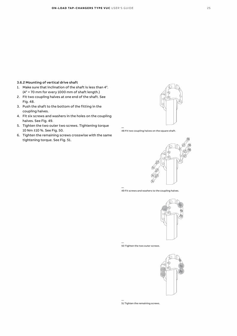
3.6.2 Mounting of vertical drive shaft1. Make sure that inclination of the shaft is less than 4°.
(4° = 70 mm for every 1000 mm of shaft length.)2. Fit two coupling halves at one end of the shaft. See
Fig. 48.3. Push the shaft to the bottom of the fitting in the
coupling halves.4. Fit six screws and washers in the holes on the coupling
halves. See Fig. 49.5. Tighten the two outer two screws. Tightening torque
10 Nm ±10 %. See Fig. 50.6. Tighten the remaining screws crosswise with the same
tightening torque. See Fig. 51.
—48 Fit two coupling halves on the square shaft.
—49 Fit screws and washers to the coupling halves.
—50 Tighten the two outer screws.
—51 Tighten the remaining screws.

26 O N - LOA D TA P - CH A N G E R S T Y PE V U C USER ' S G U I D E
Multi-hole coupling flanges
Multi-hole coupling flanges
—52 Connect the square shaft to the bevel gear.
—53 Place protective tubes on the vertical drive shaft.
—54 Fit two hose clips.
—55 BUL multi-hole coupling.
—56 BUE multi-hole coupling.
7. Connect the shaft with the mounted coupling halves to the shaft of the bevel gear. See Fig. 52.
8. Place the two protective tubes on the vertical drive shaft. See Fig. 53.
9. Fit two hose clips. See Fig. 54.10. For BUL motor-drive mechanism, loosen the two screws
on the multi-hole coupling at the top of the motor-drive mechanism. See Fig. 55.
11. For BUE motor-drive mechanism, loosen the two screws on the multi-hole coupling inside the motor-drive mechanism. See Fig. 56.

O N - LOA D TA P - CH A N G E R S T Y PE V U C USER ' S G U I D E 27
2 mm
—57 Coupling halves offset by 90°.
—58 Connect the square shaft to the motor-drive mechanism.
—59 Check that the shaft cannot be moved more than 2 mm in the axial direction.
12. Apply a thin layer of grease to all spherical shaft ends and unpainted surfaces of the bevel gears. Use any of the greases specified in Section 3.3.
13. Fit two coupling halves at the bottom end of the shaft; see Fig. 48. Be sure to offset these coupling halves 90° in relation to the couplings mounted in step 2 as shown in Fig. 57.
14. Connect the bottom end of the square shaft with the mounted coupling halves to the shaft of the motor-drive mechanism. See Fig. 58.
15. Fit six screws and washers in the holes on the coupling halves (see Fig. 49) and tighten them lightly.
16. Check that the shaft cannot be moved more than 2 mm in the axial direction (axial play). See Fig. 59. If necessary, adjust the axial play by moving the couplings on the shaft end.
17. Tighten the two outer screws; see Fig. 50. Tightening torque 10 Nm ±10 %.
18. Tighten the remaining screws crosswise (see Fig. 51) with the same tightening torque.
28 O N - LOA D TA P - CH A N G E R S T Y PE V U C USER ' S G U I D E
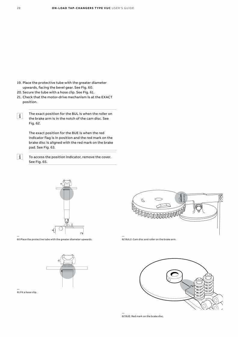
—62 BUL2: Cam disc and roller on the brake arm.
—62 BUE: Red mark on the brake disc.
19. Place the protective tube with the greater diameter upwards, facing the bevel gear. See Fig. 60.
20. Secure the tube with a hose clip. See Fig. 61.21. Check that the motor-drive mechanism is at the EXACT
position.
The exact position for the BUL is when the roller on the brake arm is in the notch of the cam disc. See Fig. 62.
The exact position for the BUE is when the red indicator flag is in position and the red mark on the brake disc is aligned with the red mark on the brake pad. See Fig. 63.
To access the position indicator, remove the cover. See Fig. 65.
—61 Fit a hose clip.
—60 Place the protective tube with the greater diameter upwards.
O N - LOA D TA P - CH A N G E R S T Y PE V U C USER ' S G U I D E 29
9 9 9 9 8 7
LOWER POSITION RAISE
9876
54
10 11 121314
– +
9876
54
10 11 121314
– +
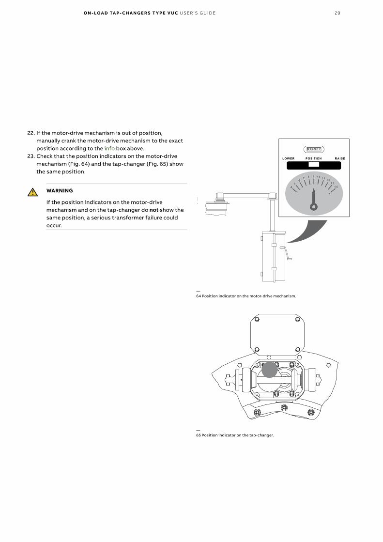
—64 Position indicator on the motor-drive mechanism.
—65 Position indicator on the tap-changer.
22. If the motor-drive mechanism is out of position, manually crank the motor-drive mechanism to the exact position according to the info box above.
23. Check that the position indicators on the motor-drive mechanism (Fig. 64) and the tap-changer (Fig. 65) show the same position.
WARNING
If the position indicators on the motor-drive mechanism and on the tap-changer do not show the same position, a serious transformer failure could occur.

30 O N - LOA D TA P - CH A N G E R S T Y PE V U C USER ' S G U I D E
3.7 TestingWhen testing the transformer, the tap-changer can be operated either by the hand crank or electrically. When operating electrically, the motor-drive mechanism must be connected.
1. Make sure that the motor-drive mechanism and the tap-changer show exactly the same position. See Fig. 64 and Fig. 65.
WARNING
If the position indicators on the motor-drive mechanism and on the tap-changer do not show the same position, a serious transformer failure could occur.
To access the position indicator, remove the cover. See Fig. 65.
2. Operate the tap-changer with the hand crank, counting the number of turns from the exact position until the tap-changer operates.
- For BUL – the tap-changer should operate after 11.5 ± 1 turn of the hand crank.
- For BUE – the tap-changer should operate after 19 ± 1.5 turns of the hand crank.
If it does not, one of the shaft couplings of the gears is incorrectly mounted.
3. Manually crank the motor-drive mechanism to a position in the middle of the range. See Fig. 64.
4. Turn the control selector switch to the LOCAL position. 5. Send an impulse for a raise operation.
If the phase sequence is incorrect (three-phase supply), the motor-drive mechanism starts in the lower direction. The motor-drive mechanism moves back and forth around its service position until the control selector switch is turned to 0.
6. If the phase sequence is incorrect, reverse two of the motor supply cables in order to get the correct sequence.
WARNING
Dangerous voltage!
For a BUL2 motor-drive mechanism, continue at step 7.
For a BUE motor-drive mechanism, continue at step 10.
For BUL2:7. Run the motor-drive mechanism.8. Check that the center of the notch in the cam disc stops
within ±2 mm of the center of the roller on the brake arm. See Fig. 62.
If it does not stop within the tolerances, see the maintenance guide for the motor-drive mechanism.
9. Continue to step 14.
For BUE:10. Run the motor-drive mechanism.11. Check that the red mark on the brake disc stops within
the tolerance limits. See Fig. 64.12. If the brake disc is outside the tolerance limits, increase
or decrease pressure on the springs; see the maintenance guide for the motor-drive mechanism.
13. Continue to step 14.
For BUE and BUL14. Check that the position indicator on the motor-drive
mechanism shows the same position as the indicator inside the cover of the tap-changer. See Figs. 64 and 65.
WARNING
If the position indicators on the motor-drive mechanism and on the tap-changer do not show the same position, a serious transformer failure could occur.
To access the position indicator, remove the cover. See Fig. 65.
O N - LOA D TA P - CH A N G E R S T Y PE V U C USER ' S G U I D E 31
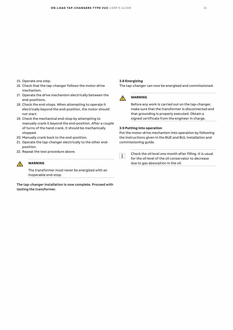
15. Operate one step.16. Check that the tap-changer follows the motor-drive
mechanism.17. Operate the drive mechanism electrically between the
end-positions. 18. Check the end-stops. When attempting to operate it
electrically beyond the end-position, the motor should not start.
19. Check the mechanical end-stop by attempting to manually crank it beyond the end-position. After a couple of turns of the hand crank, it should be mechanically stopped.
20. Manually crank back to the end-position. 21. Operate the tap-changer electrically to the other end-
position.22. Repeat the test procedure above.
WARNING
The transformer must never be energized with an inoperable end-stop.
The tap-changer installation is now complete. Proceed with testing the transformer.
3.8 EnergizingThe tap-changer can now be energized and commissioned.
WARNING
Before any work is carried out on the tap-changer, make sure that the transformer is disconnected and that grounding is properly executed. Obtain a signed certificate from the engineer in charge.
3.9 Putting into operationPut the motor-drive mechanism into operation by following the instructions given in the BUE and BUL installation and commissioning guide.
Check the oil level one month after filling. It is usual for the oil level of the oil conservator to decrease due to gas absorption in the oil.

32 O N - LOA D TA P - CH A N G E R S T Y PE V U C USER ' S G U I D E
—4. Operation
1
2
3
WARNING
Small amounts of explosive gases are constantly discharged from the breathing devices (dehydrating breather or one-way breather). Make sure that no open fires, hot surfaces or sparks are present in the immediate surroundings of the breathing devices.
CAUTION
The hand crank must not be inserted during electrical operation.
The pressure relay is a calibrated monitoring instrument. It must be handled with care and protected against careless handling or any kind of mechanical damage.
If a power supply failure occurs during operation, the interrupted operation will be completed once the power returns.
If the tap-changer is not at its exact position and the hand crank is pulled out, the motor-drive mechanism will start and go to the exact position if the power supply is on.
4.1 Synchronization between tap-changer and motor-drive mechanism1. Loosen the multi-hole coupling. Turn the shaft first to
the end-position on one side, and then to the end-position on the other side. Finally, turn halfway back. See Fig. 66.
2. Check which two holes of the upper multi-hole coupling flange coincide with two holes of the lower multi-hole coupling flange of the motor-drive mechanism. See Figs. 55 (BUL) and 56 (BUE).
3. Fit two screws and locking nuts in the two multi-hole coupling holes that best coincide. Tighten the screws. Tightening torque 10 Nm ±10 %.
4. Pull down the protective tube. See Fig. 67.5. To allow draining from the protective tubes, the amount
of clearance at the bottom of the tube is important:6. Make sure that the clearance at the bottom of the tube is
between 3 and 5 mm. See Fig. 68.7. Secure the tube with the hose clip. See Fig. 69.
3 - 5 mm
—66 Turning the shaft between end-positions.
—67 Pull down the protective tube.
—68 Clearance at the bottom of the tube.
—69 Secure the hose clip.

O N - LOA D TA P - CH A N G E R S T Y PE V U C USER ' S G U I D E 33
The inspection consists of a visual check of the motor-drive mechanism and the conservator. The quality of the insulating oil is also checked. During this inspection, the counter is read to determine when maintenance is due. See Table 1.
WARNING
The inspection must be carried out from ground level since the transformer is energized.
CAUTION
Permission must be obtained for inspection as well as for operation of the tap-changer.
1. Check the motor on the motor-drive mechanism.2. Check the counter on the motor-drive mechanism.3. Check the heater on the motor-drive mechanism.4. Register the counter’s value on the motor-drive
mechanism.
Follow the instructions given in the separate guide for the motor-drive mechanism.
The registered number of operations should be noted each time inspection and maintenance are conducted.
5. Check the oil level in the conservator. The level must be as stipulated in the instructions from the transformer manufacturer.
WARNING
The oil in the tap-changer housing may be hot. Observe caution!
6. Check the breather according to the instructions from the transformer manufacturer. If more than half of the drying agent has changed color, it must be dried or replaced. The drying agent normally starts to change color from the bottom of the breather. If it changes color at the top of the breather, there is a leakage in the connections to the conservator. Locate the leakage and seal it.
The VUC tap-changer has been designed to provide maximum reliability. The simple and robust design provides a service life equal to the service life of the transformer. A minimum of maintenance is required for trouble-free operation.
5.1 GeneralMaintenance of the tap-changer is organized into three major steps:• Inspection – Carried out by site personnel.• Maintenance – Carried out by ABB personnel.• Replacement of the complete switching mechanism
including vacuum interrupters – Carried out by the manufacturer.
Furthermore, the quality of the oil must be checked according to IEC 60422:2005. This is carried out by site personnel.
WARNING
Before any work is carried out on the tap-changer, make sure that the transformer is disconnected and that grounding is properly executed. Obtain a signed certificate from the engineer in charge.
Before starting any work inside the motor-drive mechanism, the auxiliary power must be switched off. Note that the motor, contactors and heating element may be energized from separate sources.
CAUTION
Before carrying out work on the tap-changer, put the LOCAL/REMOTE switch on the motor-drive mechanism to position ”0”. Shutting the door of the motor-drive mechanism and locking it with a padlock is also recommended when work is carried out on the tap-changer. The key should be kept by the technician. This is done to avoid unexpected starting of the motor-drive mechanism.
Be aware of the risk of slipping due to spilled oil.
5.2 InspectionIt is recommended that the tap-changer be inspected at the same time as other work is carried out on the transformer. The inspection should be carried out yearly, and can be done while the transformer is in service. This inspection is carried out by site personnel.
—5. Inspection

34 O N - LOA D TA P - CH A N G E R S T Y PE V U C USER ' S G U I D E
WARNING
The breathers and the tube from the conservator contain explosive gases. No open fires, hot surfaces or sparks may be present when removing the breather.
5.3 Oil sampling When an oil sample is to be taken (Table 1), it is recommended to do so in time before a planned stop. Maintenance may be necessary based on the test results. The test results should be documented.
Before starting any work, the section referring to oil testing and oil draining should be read and fully understood.
WARNING
When opening the valve, large amounts of oil can come out from the tap-changer. Be ready to close the valve when enough oil has been removed.
Recommended tools:• Protective gloves• Oil sampling container• Test equipment according to IEC 60156 (breakdown
voltage)• Test equipment according to IEC 60475 (sampling
insulation liquids)• Pen and note pad
5.3.1 ConservatorIt is recommended to have enough oil in the conservator to allow for oil samples to be taken, until the first maintenance stop, without adding any new oil.
The conservator for vacuum type tap-changers shall be 15 liters larger than a conventional tap-changer conservator.
Material to take oil and gas samples can be ordered from ABB. Included in the box is also an instruction how to perform the test. (If other laboratory is used the instruction may not exist).
When taking oil samples, please note that the oil level in the conservator is lowered as the oil volume decreases.
Table 1. Recommended inspection and maintenance schedule.
Time or number of operations
Inspection Oil sampling Maintenance (see also section 5.4) End of life
YearlyAfter 2, 6, 11 and 15 years
300 000 operations
600 000 operations
900 000 operations 1 200 000 1 500 000
Type of action
Check oil level at conservator x x x x
Check the breather x x x x
Visual check of motor-drive mechanism x x x x
Test of oil quality (IEC 60422, 2005-10) x x x x
Dissolved gas analysis (DGA) x x x x
Measure the transition resistors x x x
Cleaning the diverter switch and housing x x x
Oil filtration or replacement x x x
Measure the wear of the vacuum interrupters x x x
Inspection of check points x x x
Replacement of vacuum diverter switch x
Replacement of diverter switch and housing x
Replacement of tap selector x

O N - LOA D TA P - CH A N G E R S T Y PE V U C USER ' S G U I D E 35
5.3.2 Sampling procedure for tap-changers• Open the sample valve and remove at least the volume of
the tube between the diverter switch housing and the valve, plus one extra liter. See Fig. 70.
• Use a clean container when taking the oil sample for testing.
• Use the appropriate method stated in IEC 60475 and IEC 60422
Plastic bottles should not be used for DGA and dielectric breakdown, since the plastic can affect the result. If plastic bottles are used, they must be compatible to oil.
For further information about transportation and storage, see IEC 60475.
5.3.3 Information about the sampleAt least following data should be taken and sent together with the result to ABB:
Transformer and tap-changer
Customer
Transformer manufacturer
Identification number of the transformer
Type of transformer
Type of tap-changer
Serial number of the tap-changer
Type of liquid
Sampling
Sampling date
Sampling occasion after commissioning
Oil temperature
5.4 MaintenanceFor maintenance, please contact ABB or make sure that personnel performing maintenance are trained and certified by ABB.
Depending on the application, load and environment, it is recommendable to perform one maintenance (cleaning and inspection) during the transformer life. The figure of 15 years stated on the rating plate is provided as a guideline.
5.5 Replacement of the complete switching mechanism including vacuum interruptersThe vacuum interrupters are sensitive and the settings must be exact. It is thus important that replacement is performed by an ABB-certified technician. Contact ABB or make sure that personnel performing replacement of the complete switching mechanism including vacuum interrupters are trained and certified by ABB.
Extra oil valve shall be removed and used as a sample valve
Oil valve
Tap-changer top cover
Transformer cover
Tube ½”
—70 Extra oil sampling valve. The valve is removed and then refitted at the end of the sampling tube.

36 O N - LOA D TA P - CH A N G E R S T Y PE V U C USER ' S G U I D E
6.1 Standard circuit diagram BUE
SUPPLY FOR MOTOR
TAP-CHANGE IN POSITION
TAP-CHANGE IN PROGRESS
TAP-CHANGE IN PROGRESS
OPEN AT LOWER LIMIT
CLOSED AT LOWER LIMIT
OPEN AT UPPER LIMIT
CLOSED AT UPPER LIMIT
ITEM Q1 OFF/RUN-THROUGH ALARM
STEP-BY-STEP DE-ENERGIZED
REMOTE 0 LOCAL
SUPPLY FOR HEATER SUPPLY FOR CONTROL CIRCUIT
1) CONTINUATION CONTACT INCLUDED ONLY WHEN THE TAP-CHANGER HAS THROUGH-POSITIONS. CLOSED WHEN THE TAP-CHANGER IS AT THROUGH-POSITIONS.
HOLDING CIRCUIT INITIATIONLOWER REMOTE
TRIPPINGRAISE
—6. Electrical diagrams
On the following pages, the standard circuit diagrams and the contact timing diagrams for BUE and BUL2 are shown. Be sure to use the diagrams delivered with your tap-changer.
O N - LOA D TA P - CH A N G E R S T Y PE V U C USER ' S G U I D E 37
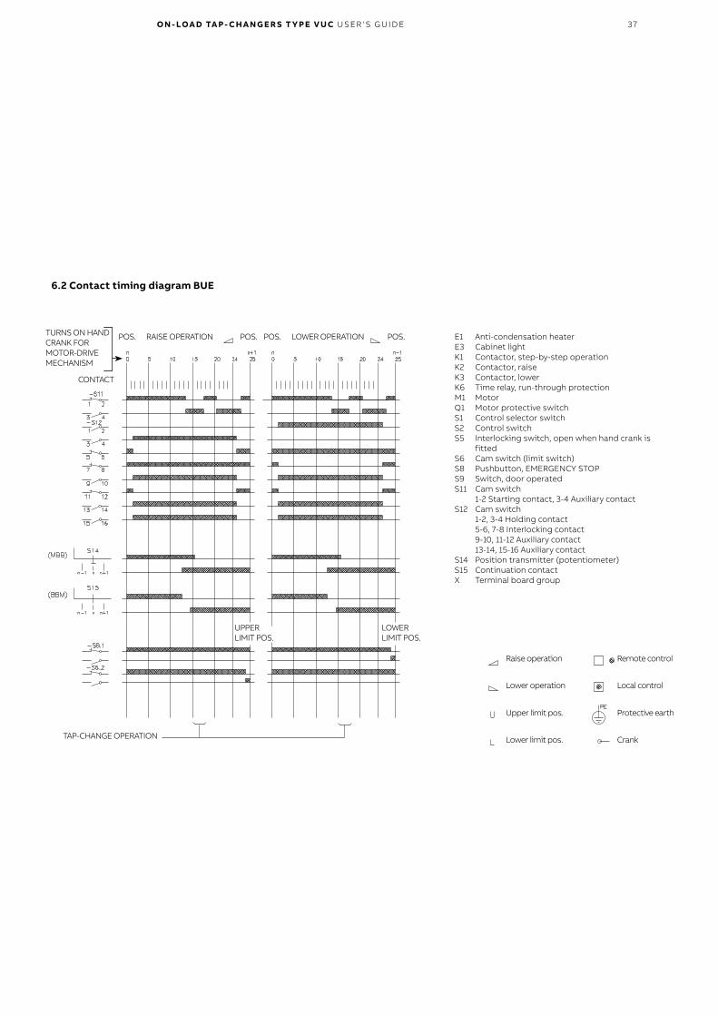
6.2 Contact timing diagram BUE
TURNS ON HAND CRANK FOR MOTOR-DRIVE MECHANISM
POS. POS. POS. POS.RAISE OPERATION
TAP-CHANGE OPERATION
UPPER LIMIT POS.
LOWER LIMIT POS.
LOWER OPERATION E1 Anti-condensation heaterE3 Cabinet lightK1 Contactor, step-by-step operationK2 Contactor, raiseK3 Contactor, lowerK6 Time relay, run-through protectionM1 MotorQ1 Motor protective switchS1 Control selector switchS2 Control switchS5 Interlocking switch, open when hand crank is
fittedS6 Cam switch (limit switch)S8 Pushbutton, EMERGENCY STOPS9 Switch, door operatedS11 Cam switch 1-2 Starting contact, 3-4 Auxiliary contactS12 Cam switch 1-2, 3-4 Holding contact 5-6, 7-8 Interlocking contact 9-10, 11-12 Auxiliary contact 13-14, 15-16 Auxiliary contactS14 Position transmitter (potentiometer)S15 Continuation contactX Terminal board group
Remote control
Local control
Protective earth
Crank
Raise operation
Lower operation
Upper limit pos.
Lower limit pos.
CONTACT

38 O N - LOA D TA P - CH A N G E R S T Y PE V U C USER ' S G U I D E
6.3 Standard circuit diagram BUL2
UPPER LIMIT
ITEM F2 OFF
LOWER LIMIT CLOSED AT UPPER LIMIT
SUPPLY FOR MOTOR SUPPLY FOR HEATER SUPPLY FOR CONTROL CONTACT
HOLDING CIRCUIT INITIATIONPREPARED FOR
PROTECTION RELAYREMOTE TRIPPING
PR
EPA
RE
D F
OR
OU
TLE
T. S
EE
SE
PAR
ATE
D
IAG
RA
M W
HE
N O
UT
LET
IS O
RD
ER
ED
.
CIRCUIT BREAKER OFF
1) CONTINUATION CONTACT INCLUDED ONLY WHEN OLTC HAS THROUGH-POSITIONS. CLOSED WHEN OLTC IS AT THROUGH-POSITIONS.
2) REMOVE CONNECTION X4:1-2 TO DISABLE STEP-BY-STEP FUNCTION AND X3:11-12 TO DISABLE THE RELAY K601 (RUN-THROUGH PROTECTION).
CONTACTS OPEN TOWARDS
TAP-CHANGE IN PROGRESS
CLOSED AT LOWER LIMIT
ITEM Q1 ON
ITEM Q1 OFF/RUN-THROUGH ALARM
ITEM Q1 OFF
STEP-BY-STEP IN OPERATION
TAP-CHANGE INCOMPLETE
STEP-BY-STEP DE-ENERGIZED
REMOTE
REMOTE
0
0
LOCAL
LOCAL

O N - LOA D TA P - CH A N G E R S T Y PE V U C USER ' S G U I D E 39
(S14)
(S15)
6.4 Contact timing diagram BUL2
TURNS ON THE HAND-CRANK OF MOTOR-DRIVE MECHANISM
POS.
CONTACT
POS.
(MBB)
(BBM)
POS. POS.
TAP-CHANGE OPERATION
UPPER LIMIT POS.
LOWER LIMIT POS.
B1 ThermostatE1 Anti-condensation heaterE2 HeaterE3 LampF1 Circuit breaker, heater circuitF2 Circuit breaker, control circuitK1 Contactor, step-by-step operationK2 Motor contactorK3 Motor contactorK601 Time relay, running-through protectionK602 Time relay, tap change incompleteM1 MotorQ1 Protective motor switchS1 Control selector switchS2 Control switchS3/S4 Cam operated contacts 33-34 Maintaining contact 41-42 Interlocking contact 13-14, 21-22 Auxiliary contactS5 Interlocking switch, open when hand crank is fittedS6/S7 Limit switch, upper/lower limit positionS8 Pushbutton, EMERGENCY STOPS9 Switch, door operatedS14 Position transmitter (potentiometer)S15 Continuation contactU5 Power supply unit, 100-240 V AC /24 V DCX Terminal board groupX3x Internal terminal board group
n → n+1 1 tap LOCAL control
n → n-1 1 tap REMOTE control
U Upper limit-positionPE
Protective ground
L Lower limit-position Crank
40 O N - LOA D TA P - CH A N G E R S T Y PE V U C USER ' S G U I D E
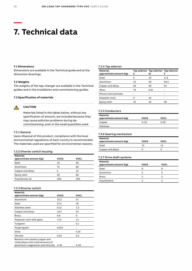
7.1 DimensionsDimensions are available in the Technical guide and at the dimension drawings.
7.2 WeightsThe weights of the tap-changer are available in the Technical guides and in the Installation and commissioning guides.
7.3 Specification of materials
CAUTION
Materials listed in the tables below, without any specification of amount, are included because they may cause pollution problems during de-commissioning, even in the small quantities used.
7.3.1 GeneralUpon disposal of this product, compliance with the local environmental regulations of each country is recommended. The materials used are specified for environmental reasons.
7.3.2 Diverter switch housingMaterial,approximate amount (kg) VUCG VUCL
Steel 15 40
Aluminium 75 80
Copper and alloys 5 10
Epoxy resin 35 60
Transformer oil 200 300
7.3.3 Diverter switchMaterial,approximate amount (kg) VUCG VUCL
Aluminium 15.2 27
Steel 27.3 36
Stainless steel 0.12 1.2
Copper and alloys 14.2 24
Brass 4.8 6
Polyester resin with glass 7.12 13
Tungsten - 0.1
Polypropylen 0.022 -
Silver - 0.16
Chrome 0.24 0.3
Resistor wire (mainly copper and nickel alloys with small amounts of aluminium, magnesium and chrome) 4-45 4-45
7.3.4 Tap selectorMaterial,approximate amount (kg)
Tap selectorC
Tap selectorIII
Tap selectorF
Steel 5 10 113
Aluminium 15 40 94.5
Copper and alloys 20 50 52
Silver 70 0.01 -
Phenol resin laminate - - -
Polyester resin 5 10 -
Epoxy resin 15 20 46
7.3.5 ConductorsMaterialapproximate amount (kg) VUCG VUCL
Copper 5–10 5-20
Cellulose
7.3.6 Gearing mechanismMaterialapproximate amount (kg) VUCG VUCL
Steel 15 15
Copper and alloys 5 5
7.3.7 Drive shaft systemsMaterialapproximate amount (kg) VUCG VUCL
Steel 8 8
Aluminium 2 2
Brass 2 2
Polyethylene 2 2
—7. Technical data


—ABB AB, ComponentsSE-771 80 LudvikaSwedenE-mail: [email protected]
www.abb.com/transformercomponents
1ZS
C0
00
56
2-A
BE
en
, Rev
. 2, 2
018
-04
-15
© Copyright 2018 ABB. All rights reserved. Specifications subject to change without notice.