on-board diagnostic and tuning interface - us shiftusshift.com/downloads/q4-uimanual.pdf · the 3-2...
TRANSCRIPT

On-Board Diagnostic and Tuning Interface

2
US Shift Transmission Control System
On-Board Diagnostic and Tuning Interface Operation Guide
www.USshift.com
Baumann Electronic Controls, LLC.
Phone: (864) 646-8920
Email: [email protected]
Address: 207 Mistr Lane, Pickens, SC 29671
This work and the ideas and processes contained herein are the exclusive property
of Baumann Electronic Controls, LLC and may not be copied, reproduced, or
distributed in any form without the express written consent of Baumann Electronic
Controls, LLC or Karl Baumann. The technology and processes contained in this
product are proprietary and may be used only on a single unit basis or as defined by
the written permission of Baumann Electronic Controls, LLC.
vF4.0.1 © Copyright 1997 - 2017 by Baumann Electronic Controls, LLC.
All rights reserved.
WARRANTY Baumann Electronic Controls, LLC. is dedicated to producing the highest quality products available in the industry and is committed to customer satisfaction. Because we have no control over the circumstances under which our products are used, we can assume no more responsibility for damages (consequential or otherwise) or defects in materials and workmanship than the original purchase price of our product. Baumann Electronic Controls, LLC. will repair or replace all defective components unconditionally for a period of five years from the date of sale. This warranty does not cover damages due to abuse, improper application, or connection of the device. After the warranty period, Baumann Electronic Controls, LLC. will service this device for a nominal fee.

3
INTRODUCTION The built-in Quick 4 User Interface allows most sensor values to be viewed, while also allowing the transmission to be manually shifted. With firmware version 3.0 or later, self-contained, basic tuning of transmission settings is also possible via the tuning menu. In addition, a computer running our included tuning software can be connected to provide advanced tuning options.
___________________________________________________________________
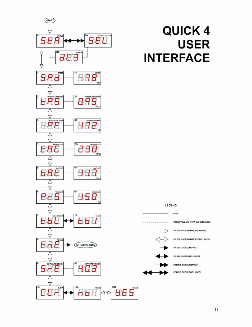
MAIN MENU For most selections in the main menu, the three letter mode name is shown on the display for 2.5 seconds after the mode is selected by rotating the function knob. The mode name is also displayed at any time when the function knob is pressed in (in all modes other than "Status" and “Tuning” modes).
OFF In this mode the display is blank and nothing is shown.
StA = Status Display This mode is the default display mode. The first character indicates the selected transmission range (P, r, n, o, d, 2, 1). or "E" if there is an error with the PRNDL switch (range sensor or pressure switch module). The second character is normally blank, but will show "P" if Manutronic Pushbutton shift mode is active or an "L" if manual selection mode is active. The third character indicates the currently commanded or selected transmission gear. There is also a small dot at the upper-left-hand corner of the third display character (similar to an apostrophe). This dot will illuminate when the torque converter clutch is engaged.
4
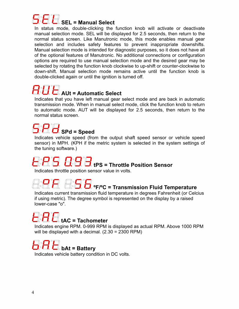
SEL = Manual Select In status mode, double-clicking the function knob will activate or deactivate manual selection mode. SEL will be displayed for 2.5 seconds, then return to the normal status screen. Like Manutronic mode, this mode enables manual gear selection and includes safety features to prevent inappropriate downshifts. Manual selection mode is intended for diagnostic purposes, so it does not have all of the optional features of Manutronic. No additional connections or configuration options are required to use manual selection mode and the desired gear may be selected by rotating the function knob clockwise to up-shift or counter-clockwise to down-shift. Manual selection mode remains active until the function knob is double-clicked again or until the ignition is turned off.
AUt = Automatic Select Indicates that you have left manual gear select mode and are back in automatic transmission mode. When in manual select mode, click the function knob to return to automatic mode. AUT will be displayed for 2.5 seconds, then return to the normal status screen.
SPd = Speed Indicates vehicle speed (from the output shaft speed sensor or vehicle speed sensor) in MPH. (KPH if the metric system is selected in the system settings of the tuning software.)
tPS = Throttle Position Sensor Indicates throttle position sensor value in volts.
ºF/ºC = Transmission Fluid Temperature Indicates current transmission fluid temperature in degrees Fahrenheit (or Celcius if using metric). The degree symbol is represented on the display by a raised lower-case "o".
tAC = Tachometer Indicates engine RPM. 0-999 RPM is displayed as actual RPM. Above 1000 RPM will be displayed with a decimal. (2.30 = 2300 RPM)
bAt = Battery Indicates vehicle battery condition in DC volts.

5
PrS = Commanded Line Pressure Indicates the transmission line pressure that the controller is currently commanding in PSI. These values are based upon the normal OEM parameters for the pressure control solenoid and main regulator valve line-up for the selected transmission. The actual line pressure may vary from this value, especially if changes have been made to the main pressure regulator valve, the main regulator valve spring, the main regulator boost valve, or the pressure control (EPC) solenoid.
tbL = Table Shows the currently selected table (TB1, TB2, TB3, or TB4) after showing "TbL" for 2.5 seconds. Pressing the knob once displays "SLT" for 2.5 seconds to show that the table can be manually selected. In select mode, you can rotate the knob to select "rES", "tb1", “tb2”, “tb3”, “tb4”. rES stands for "Remote Select" and indicates that the table is selected remotely by the table select input. Remote Select mode is the power-on default. You can select tables 1-4 to override the table select input and force the Quick 4 to use a specific table. Once you have selected the desired table or mode, you can exit select mode by pressing the knob once. "rET" will then be displayed for 2.5 seconds to indicate that you have returned from select mode. The selected mode will be retained until the ignition is turned off or until you change it.
tnE = Tuning Mode Allows the most commonly-used settings (such as TPS calibration and shift points) to be adjusted directly on the controller. Press the knob once to enter Tuning Mode. Please see the “Tuning Menu Options” section for the details of the tuning mode menu. Upon entering tuning mode, a copy of the currently-selected table is created to be used as a “scratchpad” for editing, and the controller begins running off of this copy during the tuning session. This allows you to see the effects of your changes immediately, which eliminates guess-work. We refer to this functionality as "Live Editing". Another benefit of live editing is that the original calibration is preserved until you explicitly save your changes. This allows safe experimentation without modifying any of your existing settings. If you don't like the results of your changes, simply exit the tuning menu with the Discard (dIS) option or turn off the ignition. This will erase your changes and reset everything back to where it was before you entered tuning mode.
SrE = Software Revision Indicates the software and hardware revision of the controller. "MajorRev.MinorRev.HardwareRev" (ie: 4.0.3)
6
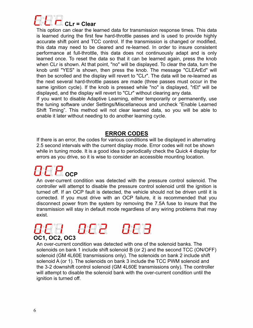
CLr = Clear This option can clear the learned data for transmission response times. This data is learned during the first few hard-throttle passes and is used to provide highly accurate shift point and TCC control. If the transmission is changed or modified, this data may need to be cleared and re-learned. In order to insure consistent performance at full-throttle, this data does not continuously adapt and is only learned once. To reset the data so that it can be learned again, press the knob when CLr is shown. At that point, "no" will be displayed. To clear the data, turn the knob until "YES" is shown, then press the knob. The message "CLEArEd" will then be scrolled and the display will revert to "CLr". The data will be re-learned as the next several hard-throttle passes are made (three passes must occur in the same ignition cycle). If the knob is pressed while "no" is displayed, "rEt" will be displayed, and the display will revert to "CLr" without clearing any data. If you want to disable Adaptive Learning, either temporarily or permanently, use the tuning software under Settings/Miscellaneous and uncheck “Enable Learned Shift Timing”. This method will not clear learned data, so you will be able to enable it later without needing to do another learning cycle.
ERROR CODES If there is an error, the codes for various conditions will be displayed in alternating 2.5 second intervals with the current display mode. Error codes will not be shown while in tuning mode. It is a good idea to periodically check the Quick 4 display for errors as you drive, so it is wise to consider an accessible mounting location.
OCP An over-current condition was detected with the pressure control solenoid. The controller will attempt to disable the pressure control solenoid until the ignition is turned off. If an OCP fault is detected, the vehicle should not be driven until it is corrected. If you must drive with an OCP failure, it is recommended that you disconnect power from the system by removing the 7.5A fuse to insure that the transmission will stay in default mode regardless of any wiring problems that may exist.
OC1, OC2, OC3
An over-current condition was detected with one of the solenoid banks. The solenoids on bank 1 include shift solenoid B (or 2) and the second TCC (ON/OFF) solenoid (GM 4L60E transmissions only). The solenoids on bank 2 include shift solenoid A (or 1). The solenoids on bank 3 include the TCC PWM solenoid and the 3-2 downshift control solenoid (GM 4L60E transmissions only). The controller will attempt to disable the solenoid bank with the over-current condition until the ignition is turned off.
7
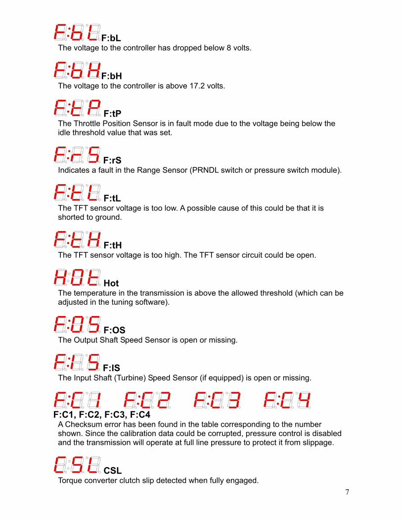
F:bL The voltage to the controller has dropped below 8 volts.
F:bH The voltage to the controller is above 17.2 volts.
F:tP The Throttle Position Sensor is in fault mode due to the voltage being below the idle threshold value that was set.
F:rS Indicates a fault in the Range Sensor (PRNDL switch or pressure switch module).
F:tL The TFT sensor voltage is too low. A possible cause of this could be that it is shorted to ground.
F:tH The TFT sensor voltage is too high. The TFT sensor circuit could be open.
Hot The temperature in the transmission is above the allowed threshold (which can be adjusted in the tuning software).
F:OS The Output Shaft Speed Sensor is open or missing.
F:IS The Input Shaft (Turbine) Speed Sensor (if equipped) is open or missing.
F:C1, F:C2, F:C3, F:C4
A Checksum error has been found in the table corresponding to the number shown. Since the calibration data could be corrupted, pressure control is disabled and the transmission will operate at full line pressure to protect it from slippage.
CSL Torque converter clutch slip detected when fully engaged.

8
F:rE Transmission gear ratio appears to be too high in at least one gear.
F:SL Transmission appears to be slipping in at least one gear.
FSS Transmission continued to slip after maximum line pressure was commanded.
rSL Transmission slip was detected more than twice in this drive cycle (max. line pressure latched).
TUNING MENU OPTIONS
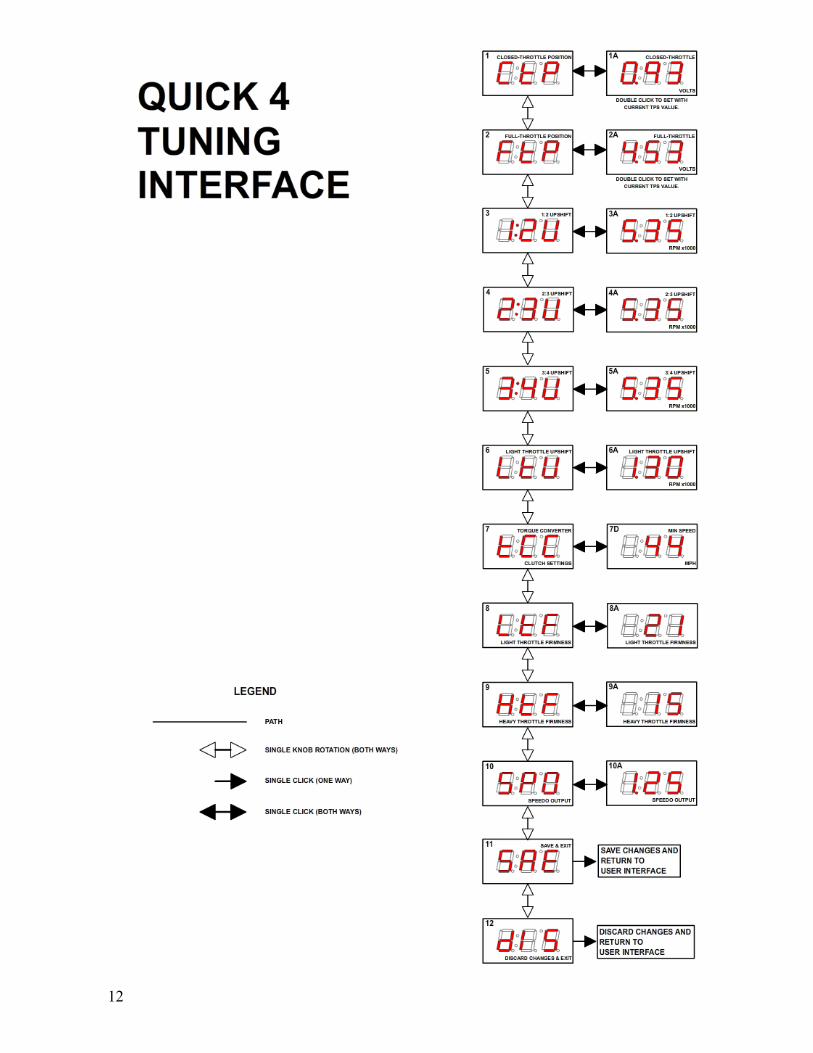
All of these settings can be changed by entering "adjustment mode" (by pressing the knob once) and turning the knob clockwise to increase the setting, or counter-clockwise to decrease it. Changes will be effective immediately, and you can return to the tuning menu by pressing the knob a second time.
CtP = Closed Throttle Position This setting is used to adjust the idle TPS (throttle position sensor) voltage threshold. This setting is important as it allows Quick 4 to determine where the idle position is and to prevent false detection of a throttle position sensor failure. Press the knob once to enter the adjustment mode and change this setting. (Press once again to return to the menu.) While in adjustment mode, you can double-click the knob (press it twice quickly) to automatically set this value to the current TPS voltage. Make sure that the throttle plate, accelerator pedal, or injector pump is at the hot idle position before automatically setting this value. If you have a carburetor, be sure that the choke is fully off and that you are on hot idle. The engine can be off for this setting as long as the ignition is on.
FtP = Full Throttle Position This setting is used to adjust the WOT (wide-open throttle) TPS (throttle position sensor) voltage threshold. This setting is important as it is used to adjust the system to the voltage span of your throttle position sensor or accelerator pedal position (APP) sensor, ensuring that the full-throttle shift points and line pressure are correct. Press the knob once to enter the adjustment mode and change this setting. (Press once again to return to the menu.) While in adjustment mode, you can double-click the knob (press it twice quickly) to automatically set this value to the current TPS voltage. Make sure that the accelerator pedal is fully depressed before automatically setting this value. For obvious reasons, the engine should be off for this setting, with the ignition on.
9
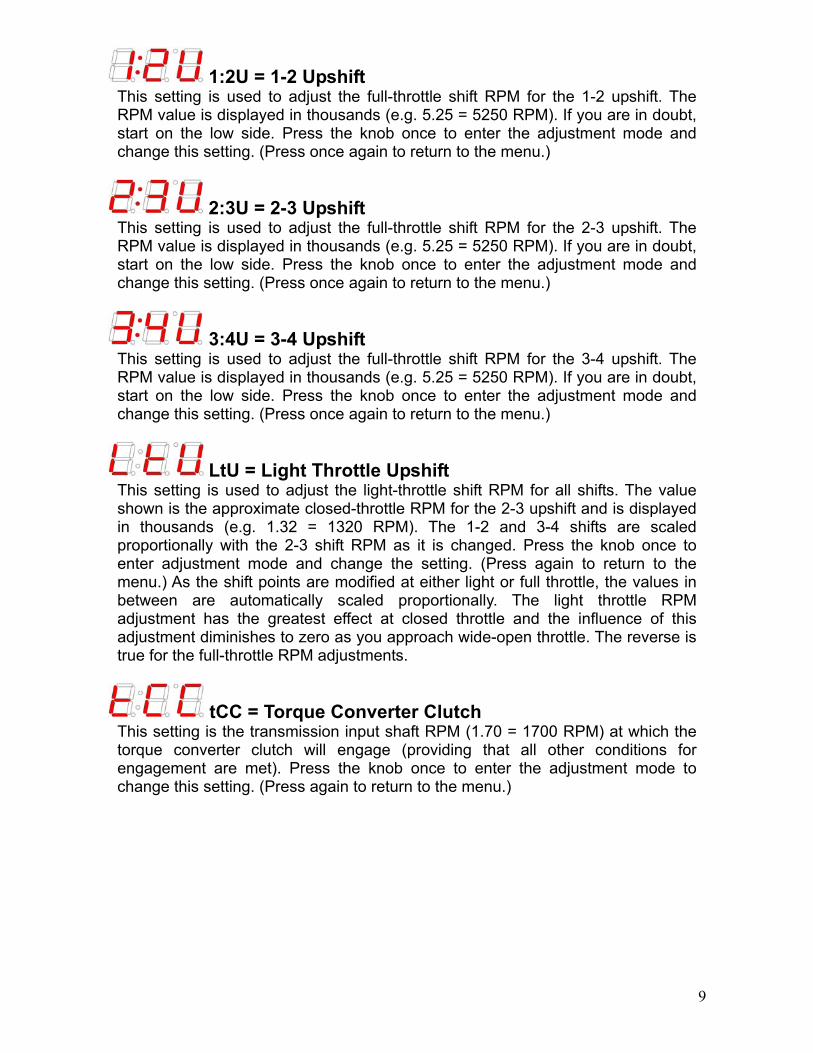
1:2U = 1-2 Upshift This setting is used to adjust the full-throttle shift RPM for the 1-2 upshift. The RPM value is displayed in thousands (e.g. 5.25 = 5250 RPM). If you are in doubt, start on the low side. Press the knob once to enter the adjustment mode and change this setting. (Press once again to return to the menu.)
2:3U = 2-3 Upshift This setting is used to adjust the full-throttle shift RPM for the 2-3 upshift. The RPM value is displayed in thousands (e.g. 5.25 = 5250 RPM). If you are in doubt, start on the low side. Press the knob once to enter the adjustment mode and change this setting. (Press once again to return to the menu.)
3:4U = 3-4 Upshift This setting is used to adjust the full-throttle shift RPM for the 3-4 upshift. The RPM value is displayed in thousands (e.g. 5.25 = 5250 RPM). If you are in doubt, start on the low side. Press the knob once to enter the adjustment mode and change this setting. (Press once again to return to the menu.)
LtU = Light Throttle Upshift This setting is used to adjust the light-throttle shift RPM for all shifts. The value shown is the approximate closed-throttle RPM for the 2-3 upshift and is displayed in thousands (e.g. 1.32 = 1320 RPM). The 1-2 and 3-4 shifts are scaled proportionally with the 2-3 shift RPM as it is changed. Press the knob once to enter adjustment mode and change the setting. (Press again to return to the menu.) As the shift points are modified at either light or full throttle, the values in between are automatically scaled proportionally. The light throttle RPM adjustment has the greatest effect at closed throttle and the influence of this adjustment diminishes to zero as you approach wide-open throttle. The reverse is true for the full-throttle RPM adjustments.
tCC = Torque Converter Clutch This setting is the transmission input shaft RPM (1.70 = 1700 RPM) at which the torque converter clutch will engage (providing that all other conditions for engagement are met). Press the knob once to enter the adjustment mode to change this setting. (Press again to return to the menu.)
10
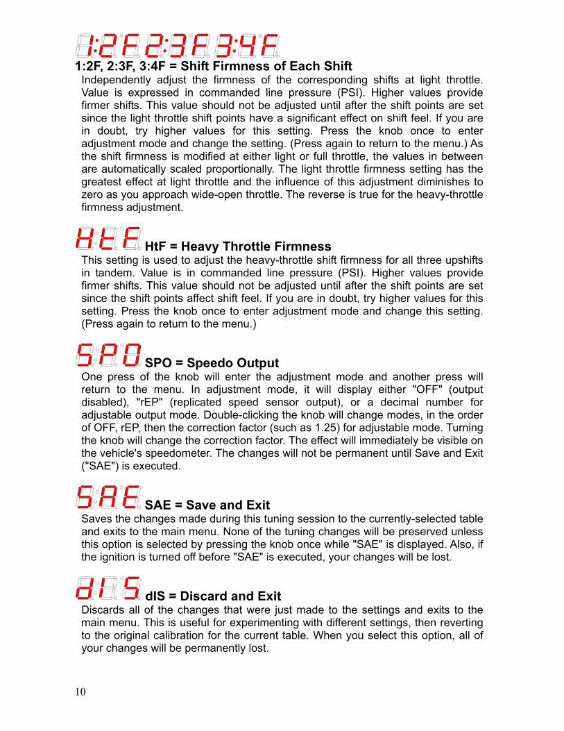
1:2F, 2:3F, 3:4F = Shift Firmness of Each Shift
Independently adjust the firmness of the corresponding shifts at light throttle. Value is expressed in commanded line pressure (PSI). Higher values provide firmer shifts. This value should not be adjusted until after the shift points are set since the light throttle shift points have a significant effect on shift feel. If you are in doubt, try higher values for this setting. Press the knob once to enter adjustment mode and change the setting. (Press again to return to the menu.) As the shift firmness is modified at either light or full throttle, the values in between are automatically scaled proportionally. The light throttle firmness setting has the greatest effect at light throttle and the influence of this adjustment diminishes to zero as you approach wide-open throttle. The reverse is true for the heavy-throttle firmness adjustment.
HtF = Heavy Throttle Firmness This setting is used to adjust the heavy-throttle shift firmness for all three upshifts in tandem. Value is in commanded line pressure (PSI). Higher values provide firmer shifts. This value should not be adjusted until after the shift points are set since the shift points affect shift feel. If you are in doubt, try higher values for this setting. Press the knob once to enter adjustment mode and change this setting. (Press again to return to the menu.)
SPO = Speedo Output One press of the knob will enter the adjustment mode and another press will return to the menu. In adjustment mode, it will display either "OFF" (output disabled), "rEP" (replicated speed sensor output), or a decimal number for adjustable output mode. Double-clicking the knob will change modes, in the order of OFF, rEP, then the correction factor (such as 1.25) for adjustable mode. Turning the knob will change the correction factor. The effect will immediately be visible on the vehicle's speedometer. The changes will not be permanent until Save and Exit ("SAE") is executed.
SAE = Save and Exit Saves the changes made during this tuning session to the currently-selected table and exits to the main menu. None of the tuning changes will be preserved unless this option is selected by pressing the knob once while "SAE" is displayed. Also, if the ignition is turned off before "SAE" is executed, your changes will be lost.
dIS = Discard and Exit Discards all of the changes that were just made to the settings and exits to the main menu. This is useful for experimenting with different settings, then reverting to the original calibration for the current table. When you select this option, all of your changes will be permanently lost.
11
12