hgm automotive electronics installation and user guide · pdf file- 3 - installation planning...
TRANSCRIPT
HGM Automotive Electronics
Installation and User Guide
Copyright © 2003 HGM Automotive Electronics
- ii -
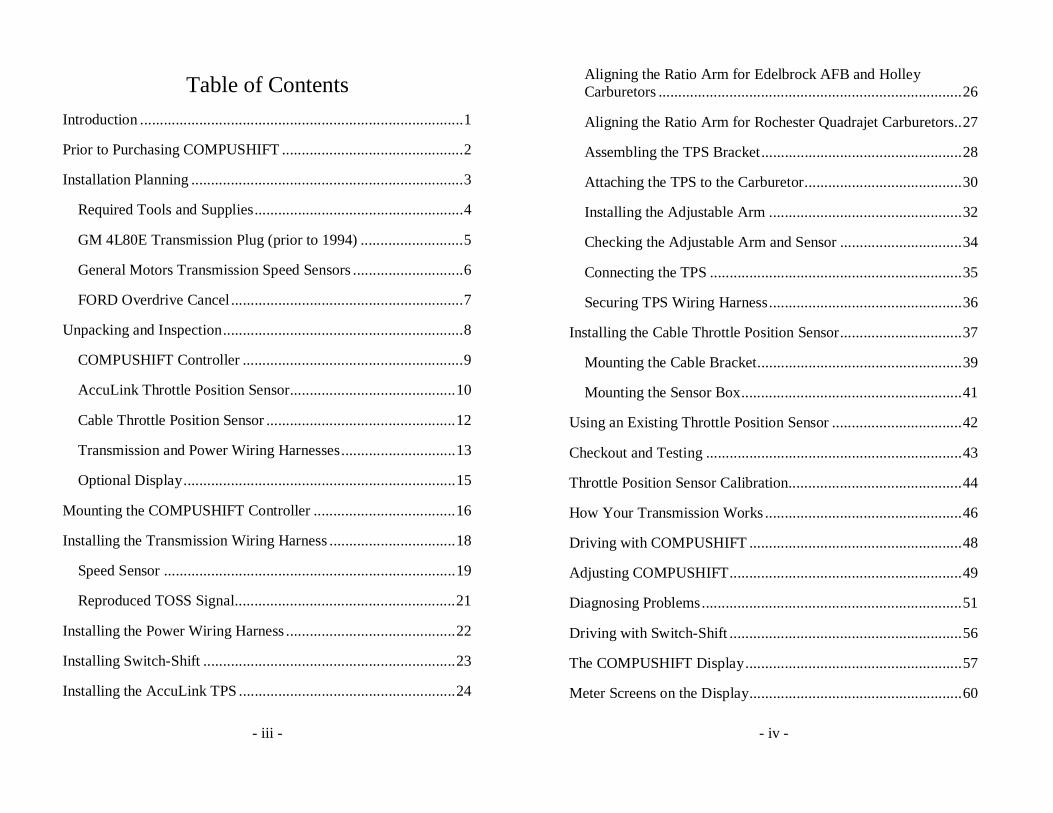
This manual, all photos, design documents and schematics are copyright © 2000-2003 by HGM Automotive Electronics Corporation. All rights reserved. No part of this book may be reproduced in any form or by any electronic or mechanical means without permission of HGM Automotive Electronics Corporation.
All software, circuit designs, and creative content in COMPUSHIFT are copyright © 1997-2003 by HGM Automotive Electronics Corporation.
HGM Automotive Electronics Corporation reserves the right to modify this document and COMPUSHIFT without notice.
COMPUSHIFT and the COMPUSHIFT logo are trademarked 2000 by HGM Automotive Electronics Corporation. All other trademarks are the sole property of their owners.
Revision 2.0.
- iii -
Table of Contents
Introduction ..................................................................................1
Prior to Purchasing COMPUSHIFT ..............................................2
Installation Planning .....................................................................3
Required Tools and Supplies.....................................................4
GM 4L80E Transmission Plug (prior to 1994) ..........................5
General Motors Transmission Speed Sensors ............................6
FORD Overdrive Cancel ...........................................................7
Unpacking and Inspection.............................................................8
COMPUSHIFT Controller ........................................................9
AccuLink Throttle Position Sensor..........................................10
Cable Throttle Position Sensor ................................................12
Transmission and Power Wiring Harnesses.............................13
Optional Display.....................................................................15
Mounting the COMPUSHIFT Controller ....................................16
Installing the Transmission Wiring Harness ................................18
Speed Sensor ..........................................................................19
Reproduced TOSS Signal........................................................21
Installing the Power Wiring Harness ...........................................22
Installing Switch-Shift ................................................................23
Installing the AccuLink TPS .......................................................24
- iv -
Aligning the Ratio Arm for Edelbrock AFB and Holley Carburetors .............................................................................26
Aligning the Ratio Arm for Rochester Quadrajet Carburetors..27
Assembling the TPS Bracket...................................................28
Attaching the TPS to the Carburetor........................................30
Installing the Adjustable Arm .................................................32
Checking the Adjustable Arm and Sensor ...............................34
Connecting the TPS ................................................................35
Securing TPS Wiring Harness.................................................36
Installing the Cable Throttle Position Sensor...............................37
Mounting the Cable Bracket....................................................39
Mounting the Sensor Box........................................................41
Using an Existing Throttle Position Sensor .................................42
Checkout and Testing .................................................................43
Throttle Position Sensor Calibration............................................44
How Your Transmission Works ..................................................46
Driving with COMPUSHIFT ......................................................48
Adjusting COMPUSHIFT...........................................................49
Diagnosing Problems..................................................................51
Driving with Switch-Shift ...........................................................56
The COMPUSHIFT Display.......................................................57
Meter Screens on the Display......................................................60
- v -
System Status..........................................................................61
Shift Pressure Adjustment .......................................................62
Shift Speed Adjustment...........................................................63
Mixed Meter Display ..............................................................64
Dynamometer / Horsepower Measurement..............................68
Accelerometer / G meter .........................................................70
Stopwatch ...............................................................................71
Data Log.................................................................................73
Large Meters...........................................................................76
Bar Graphs..............................................................................79
Setup Mode on the Display .........................................................81
Entering the SETUP mode ......................................................82
How Setup Screens Work .......................................................83
Transmission type ...................................................................85
TPS Calibration ......................................................................86
Transmission Mode.................................................................87
Shift Sequence for General Motors Transmissions ..............89
Shift Sequence for Ford Transmissions ...............................90
Shift/Press Adjust ...................................................................91
Tach Pulses / Rev....................................................................92
Speedo Pulses / Rev. ...............................................................94
Always Upshift At ..................................................................95
- vi -
Final Drive Ratio ....................................................................97
Tire Diameter..........................................................................98
Vehicle Weight .......................................................................99
TCC Enable ..........................................................................100
TCC Enable Speed................................................................101
TCC Max Throttle ................................................................102
Display Contrast ...................................................................103
Measurements.......................................................................104
Wiring Pinouts and Connections ...............................................105
ALL TRANSMISSIONS ......................................................105
ALL GM...............................................................................106
FORD E4OD & 4R100 .........................................................108
FORD 4R70W ......................................................................110
FORD AODE .......................................................................112
Controller Specifications...........................................................114
Display Specifications ..............................................................119
AccuLink Throttle Position Sensor Specifications.....................123
Cable Throttle Position Sensor Specifications ...........................124
Warranty...................................................................................126
- 1 -
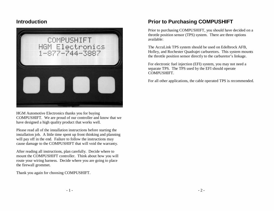
Introduction
HGM Automotive Electronics thanks you for buying COMPUSHIFT. We are proud of our controller and know that we have designed a high quality product that works well.
Please read all of the installation instructions before starting the installation job. A little time spent up front thinking and planning will pay off in the end. Failure to follow the instructions may cause damage to the COMPUSHIFT that will void the warranty.
After reading all instructions, plan carefully. Decide where to mount the COMPUSHIFT controller. Think about how you will route your wiring harness. Decide where you are going to place the firewall grommet.
Thank you again for choosing COMPUSHIFT.
- 2 -
Prior to Purchasing COMPUSHIFT
Prior to purchasing COMPUSHIFT, you should have decided on a throttle position sensor (TPS) system. There are three options available:
The AccuLink TPS system should be used on Edelbrock AFB, Holley, and Rochester Quadrajet carburetors. This system mounts the throttle position sensor directly to the carburetor’s linkage.
For electronic fuel injection (EFI) system, you may not need a separate TPS. The TPS used by the EFI should operate COMPUSHIFT.
For all other applications, the cable operated TPS is recommended.
- 3 -
Installation Planning
Your COMPUSHIFT can control the following transmissions: GM 4L60E, GM 4L80E, Ford AODE, Ford 4R100, and Ford E4OD. When you purchased your COMPUSHIFT, you specified which transmission you were going to use.
You must be certain that the transmission is properly installed and is in good mechanical condition before using COMPUSHIFT.
A qualified transmission repair shop can inspect, clean, install and/or rebuild your transmission as required. If there are any questions about the condition or type of transmission, please contact a qualified transmission repair facility, HGM, or one of our distributors for a recommendation.
COMPUSHIFT cannot properly operate a malfunctioning transmission and a malfunctioning transmission may damage COMPUSHIFT, voiding your warranty.
COMPUSHIFT can provide an electronic signal to operate an electronic speedometer. If you intend to use this feature and have not purchased the display, you must tell the factory or dealer what type of speedometer you are using so that they can calibrate COMPUSHIFT to match your speedometer.
COMPUSHIFT will also provide a signal that duplicates the speed sensor (TOSS) in your transmission. This can be used to run an original in dash speedometer, and eliminates the need for dual speed sensors.
- 4 -
Required Tools and Supplies
For installation, you will need, at a minimum, the following tools:
1. #2 Phillips screwdriver
2. 1/8” or 3/16” flat blade screwdrivers
3. Drill and small drill bit assortment
4. Socket / end-wrench assortment
5. Wire cutters
6. Wire stripping pliers
7. Soldering iron and solder or wire crimping pliers
In addition, depending on the installation, you may need the following:
1. 1.1875” and 1.625” hole saw or chassis punch
2. Tin snips
3. Center punch
4. File
5. Sheet metal tools
You may need the following supplies also:
1. Insulating tape
2. Wire crimp connectors
3. Wire spade lugs
- 5 -
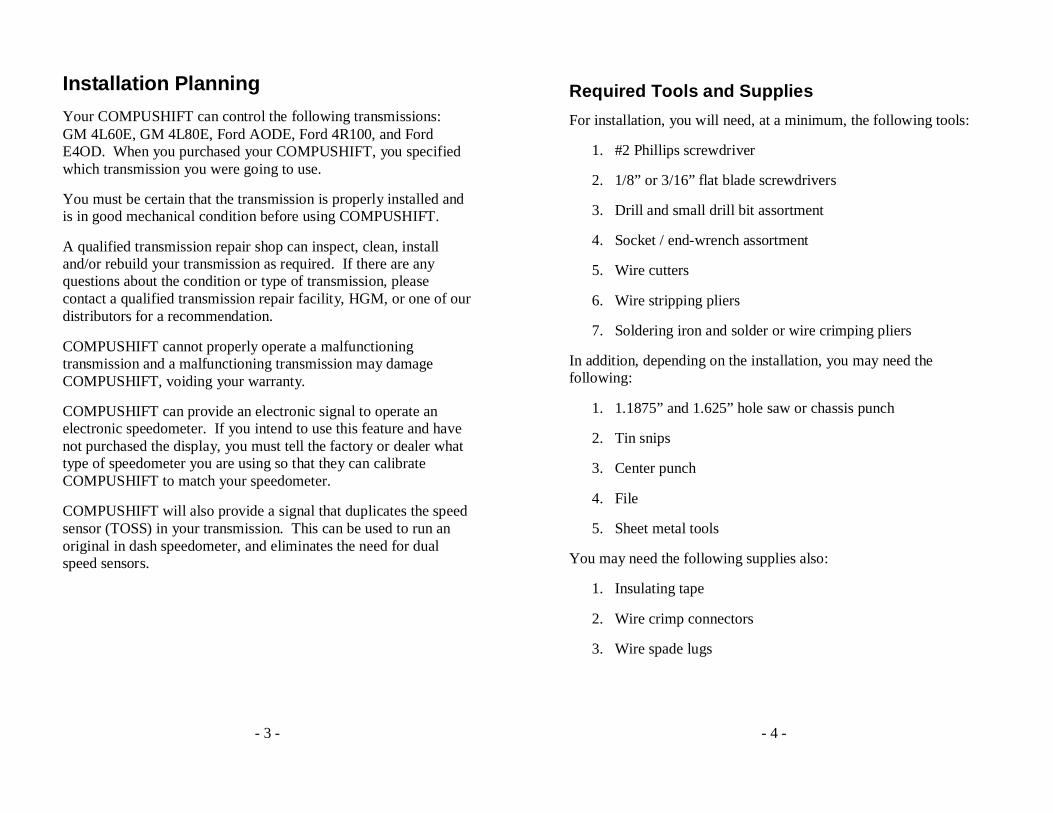
GM 4L80E Transmission Plug (prior to 1994)
The early GM 4L80E transmissions were delivered with two types of main body connectors. One of these connectors is used today and the other one, pictured above, is no longer available.
The COMPUSHIFT kit does not provide the connector for the early transmission. Fortunately, the early model transmission can easily be fitted with the internal wiring harness and plug from a late model GM 4L80E transmission. This internal wiring harness is easily installed by a qualified transmission shop and is available from General Motors with part number P/N24200161.
- 6 -
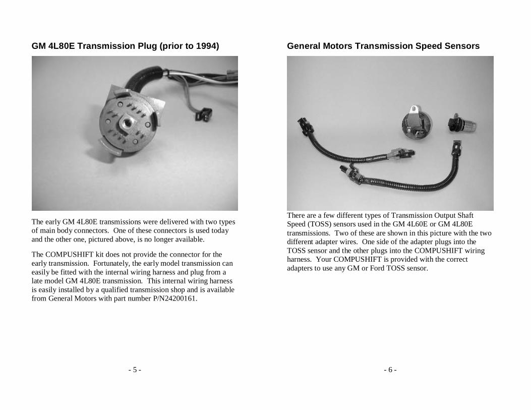
General Motors Transmission Speed Sensors
There are a few different types of Transmission Output Shaft Speed (TOSS) sensors used in the GM 4L60E or GM 4L80E transmissions. Two of these are shown in this picture with the two different adapter wires. One side of the adapter plugs into the TOSS sensor and the other plugs into the COMPUSHIFT wiring harness. Your COMPUSHIFT is provided with the correct adapters to use any GM or Ford TOSS sensor.

- 7 -
FORD Overdrive Cancel
General Motors’ transmissions have four forward speeds on the shift lever. The Ford transmissions have only three forward speeds on the shift lever. The Ford transmissions can be prevented from shifting into fourth gear with a switch. This switch is not provided with your COMPUSHIFT, though a wire to connect to your own switch is provided. This wire is clearly labeled “Overdrive Cancel” on the wiring harness and may be connected to a SPST switch that connects to ground when turned on.
The overdrive cancel wire does not need to be used unless you want the ability to prohibit fourth gear. It may be left unconnected if insulated.
- 8 -
Unpacking and Inspection
All necessary wiring harnesses, TOSS adapter cables are included with the purchase of the basic COMPUSHIFT unit. A throttle position sensor is included unless specifically omitted. The optional display, if purchased, plugs directly into the COMPUSHIFT controller.
Unpack and inspect your COMPUSHIFT transmission control system. If you purchased the basic COMPUSHIFT unit without the display, READ THE PACKING SLIP. The as shipped configuration of your COMPUSHIFT unit will be printed on the packing slip. The data on the packing slip will tell you which transmission your COMPUSHIFT is programmed to operate and what torque converter lockup and maximum upshift RPM rules have been programmed into the unit.
Be sure that COMPUSHIFT is programmed and configured properly for your intended use. For example, a COMPUSHIFT programmed to operate a GM 4L80E will not properly operate a GM 4L60E and may cause damage to the transmission.
If later you want to change the programming, any of our distributors can simply reprogram your COMPUSHIFT. You may also buy a display from the HGM factory or a distributor and reprogram your COMPUSHIFT yourself.
If you have purchased COMPUSHIFT with the display, you will be able to choose the desired configuration, or modify the configuration for COMPUSHIFT.
As you are inspecting the COMPUSHIFT kit, please refer to the pictures and identify each of the component parts of the kit.
- 9 -
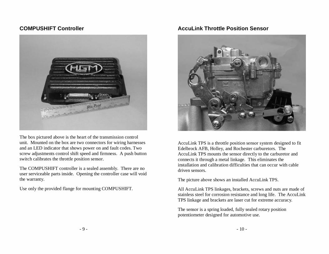
COMPUSHIFT Controller
The box pictured above is the heart of the transmission control unit. Mounted on the box are two connectors for wiring harnesses and an LED indicator that shows power on and fault codes. Two screw adjustments control shift speed and firmness. A push button switch calibrates the throttle position sensor.
The COMPUSHIFT controller is a sealed assembly. There are no user serviceable parts inside. Opening the controller case will void the warranty.
Use only the provided flange for mounting COMPUSHIFT.
- 10 -
AccuLink Throttle Position Sensor
AccuLink TPS is a throttle position sensor system designed to fit Edelbrock AFB, Holley, and Rochester carburetors. The AccuLink TPS mounts the sensor directly to the carburetor and connects it through a metal linkage. This eliminates the installation and calibration difficulties that can occur with cable driven sensors.
The picture above shows an installed AccuLink TPS.
All AccuLink TPS linkages, brackets, screws and nuts are made of stainless steel for corrosion resistance and long life. The AccuLink TPS linkage and brackets are laser cut for extreme accuracy.
The sensor is a spring loaded, fully sealed rotary position potentiometer designed for automotive use.
- 11 -
- 12 -
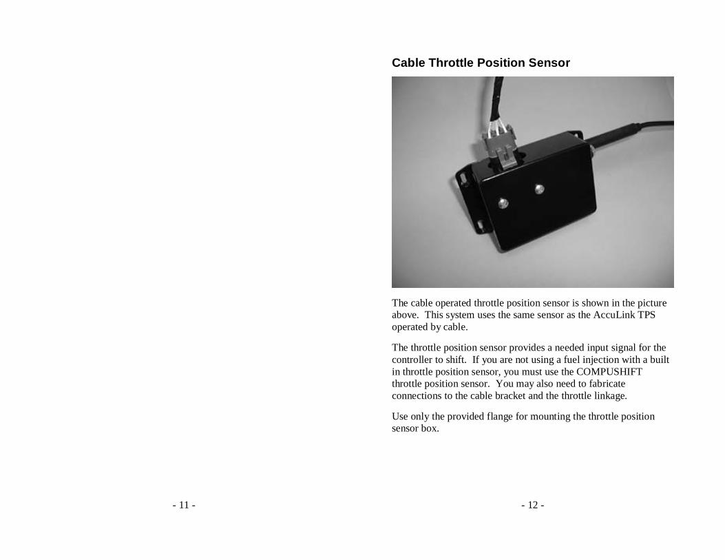
Cable Throttle Position Sensor
The cable operated throttle position sensor is shown in the picture above. This system uses the same sensor as the AccuLink TPS operated by cable.
The throttle position sensor provides a needed input signal for the controller to shift. If you are not using a fuel injection with a built in throttle position sensor, you must use the COMPUSHIFT throttle position sensor. You may also need to fabricate connections to the cable bracket and the throttle linkage.
Use only the provided flange for mounting the throttle position sensor box.
- 13 -
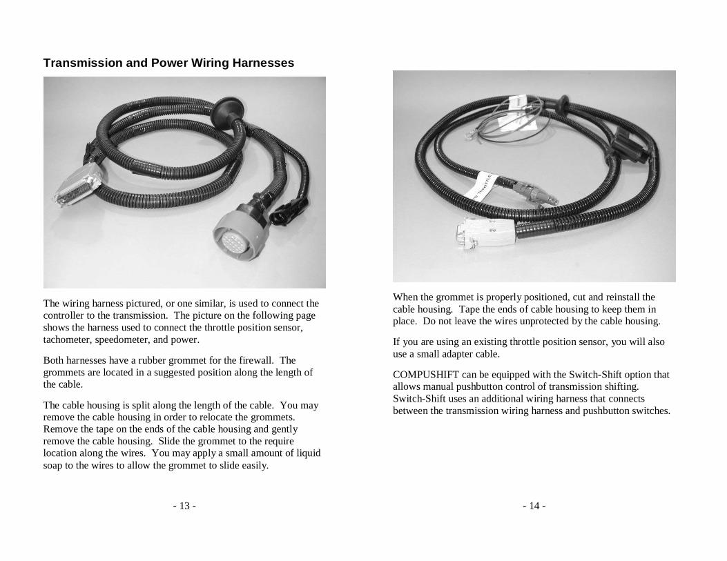
Transmission and Power Wiring Harnesses
The wiring harness pictured, or one similar, is used to connect the controller to the transmission. The picture on the following page shows the harness used to connect the throttle position sensor, tachometer, speedometer, and power.
Both harnesses have a rubber grommet for the firewall. The grommets are located in a suggested position along the length of the cable.
The cable housing is split along the length of the cable. You may remove the cable housing in order to relocate the grommets. Remove the tape on the ends of the cable housing and gently remove the cable housing. Slide the grommet to the require location along the wires. You may apply a small amount of liquid soap to the wires to allow the grommet to slide easily.
- 14 -
When the grommet is properly positioned, cut and reinstall the cable housing. Tape the ends of cable housing to keep them in place. Do not leave the wires unprotected by the cable housing.
If you are using an existing throttle position sensor, you will also use a small adapter cable.
COMPUSHIFT can be equipped with the Switch-Shift option that allows manual pushbutton control of transmission shifting. Switch-Shift uses an additional wiring harness that connects between the transmission wiring harness and pushbutton switches.
- 15 -
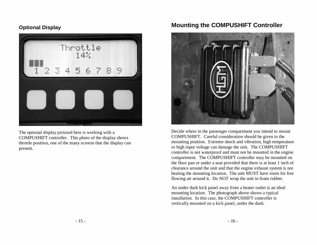
Optional Display
The optional display pictured here is working with a COMPUSHIFT controller. This photo of the display shows throttle position, one of the many screens that the display can present.
- 16 -
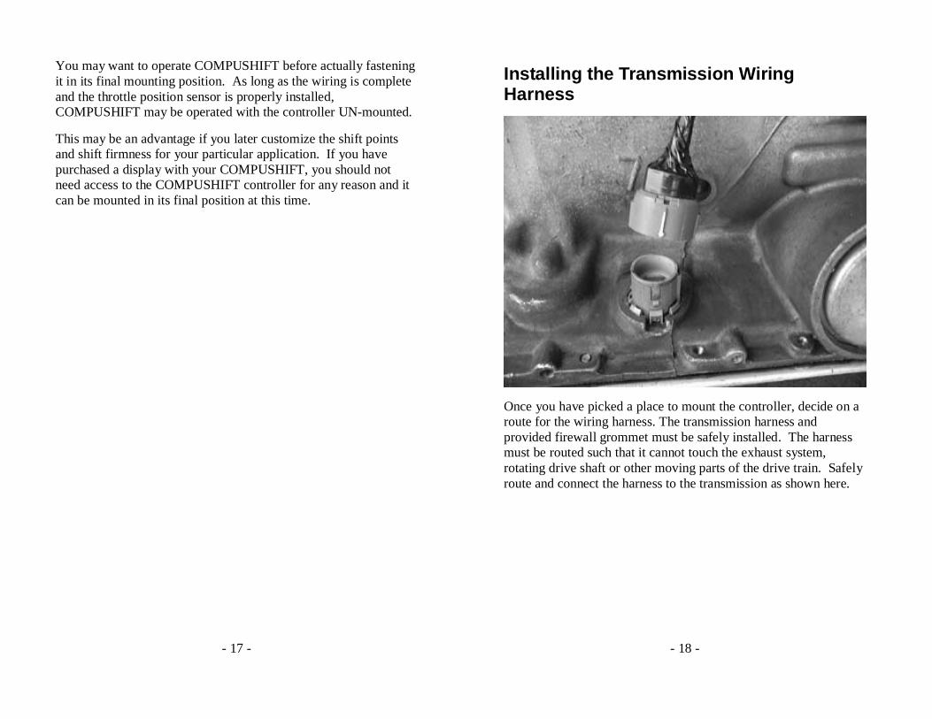
Mounting the COMPUSHIFT Controller
Decide where in the passenger compartment you intend to mount COMPUSHIFT. Careful consideration should be given to the mounting position. Extreme shock and vibration, high temperature or high input voltage can damage the unit. The COMPUSHIFT controller is not waterproof and must not be mounted in the engine compartment. The COMPUSHIFT controller may be mounted on the floor pan or under a seat provided that there is at least 1 inch of clearance around the unit and that the engine exhaust system is not heating the mounting location. The unit MUST have room for free flowing air around it. Do NOT wrap the unit in foam rubber.
An under dash kick panel away from a heater outlet is an ideal mounting location. The photograph above shows a typical installation. In this case, the COMPUSHIFT controller is vertically mounted on a kick panel, under the dash.
- 17 -
You may want to operate COMPUSHIFT before actually fastening it in its final mounting position. As long as the wiring is complete and the throttle position sensor is properly installed, COMPUSHIFT may be operated with the controller UN-mounted.
This may be an advantage if you later customize the shift points and shift firmness for your particular application. If you have purchased a display with your COMPUSHIFT, you should not need access to the COMPUSHIFT controller for any reason and it can be mounted in its final position at this time.
- 18 -
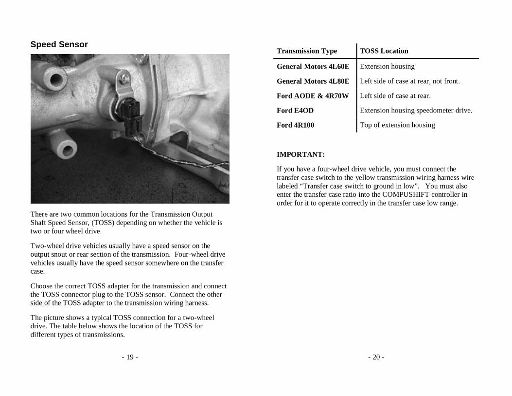
Installing the Transmission Wiring Harness
Once you have picked a place to mount the controller, decide on a route for the wiring harness. The transmission harness and provided firewall grommet must be safely installed. The harness must be routed such that it cannot touch the exhaust system, rotating drive shaft or other moving parts of the drive train. Safely route and connect the harness to the transmission as shown here.
- 19 -
Speed Sensor
There are two common locations for the Transmission Output Shaft Speed Sensor, (TOSS) depending on whether the vehicle is two or four wheel drive.
Two-wheel drive vehicles usually have a speed sensor on the output snout or rear section of the transmission. Four-wheel drive vehicles usually have the speed sensor somewhere on the transfer case.
Choose the correct TOSS adapter for the transmission and connect the TOSS connector plug to the TOSS sensor. Connect the other side of the TOSS adapter to the transmission wiring harness.
The picture shows a typical TOSS connection for a two-wheel drive. The table below shows the location of the TOSS for different types of transmissions.
- 20 -
Transmission Type TOSS Location
General Motors 4L60E Extension housing
General Motors 4L80E Left side of case at rear, not front.
Ford AODE & 4R70W Left side of case at rear.
Ford E4OD Extension housing speedometer drive.
Ford 4R100 Top of extension housing
IMPORTANT:
If you have a four-wheel drive vehicle, you must connect the transfer case switch to the yellow transmission wiring harness wire labeled “Transfer case switch to ground in low”. You must also enter the transfer case ratio into the COMPUSHIFT controller in order for it to operate correctly in the transfer case low range.
- 21 -
Reproduced TOSS Signal
Your COMPUSHIFT recreates a signal that duplicates the output of the TOSS sensor. This signal can be useful for driving an OEM engine computer or speedometer that was disconnected when you installed the COMPUSHIFT. This signal is provided on a wire in the transmission wiring harness labeled “Reproduced TOSS”. Do not attempt to connect your original TOSS sensor wires to the TOSS sensor wires that are now used by your Compushift. If you need a TOSS signal for any reason, use the reproduced signal generated by your Compushift
On GM cars, you can patch this connection to the cable that originally connected to the TOSS sensor. GM does not make a plug / cable to fit this, so you must patch the wire directly.
- 22 -
Installing the Power Wiring Harness
The power wiring harness has connections for switched +12, ground, tachometer input, speedometer output, and the throttle position sensor. Depending on your installation, you may want to move the firewall grommet as explained on page 13.
Connect the red wire marked “Switched 12 Volt power” to a circuit that is powered when your ignition switch is turned on. This circuit must supply at least 6 Amperes of current.
Connect the black wire marked “System Ground” to a good ground, preferably on the negative battery terminal or the engine block.
If you are using a COMPUSHIFT display, you may want to connect the brown wire marked “Tachometer Input.” This will let you read engine RPM on the display. This wire can be connected to the tachometer output of an electronic ignition system such as an HEI, or to the points on a conventional points type ignition system.
DO NOT CONNECT THE TACHOMETER INPUT TO THE COIL OF AN ELECTRONIC CAPACITIVE DISCHARGE (CD) IGNITION. THIS MAY DAMAGE COMPUSHIFT AND VOID YOUR WARRANTY.
If you are using an electronic speedometer, you may connect the wire marked “Speedometer Output” to your electronic speedometer.
If you are using a Ford transmission, you may connect the optional “Overdrive Cancel” wire to one side of your cancel switch. The other side of the cancel switch should be connected to ground.
- 23 -
Installing Switch-Shift
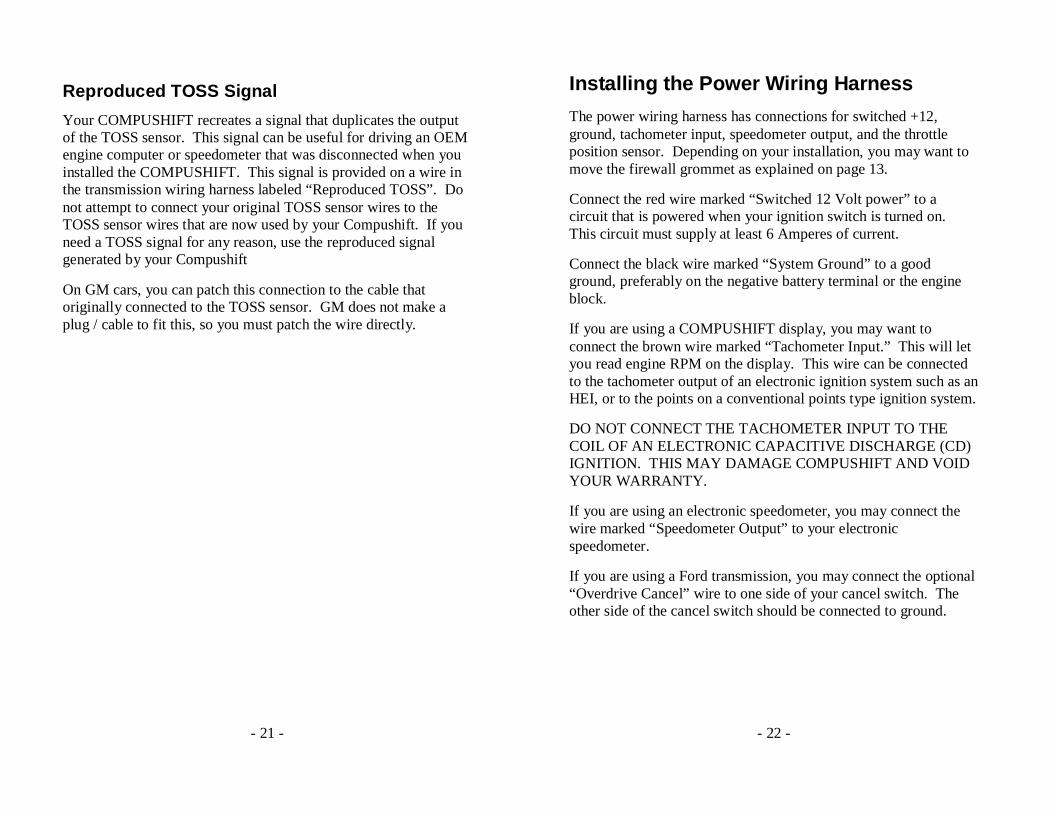
Some versions of COMPUSHIFT are equipped with the Switch-Shift feature. This feature allows you to manually upshift and downshift the transmission using a pair of pushbuttons.
The wiring harness pictured above should be connected to the transmission wiring harness and routed to your switch location. Because each Switch-Shift installation is custom, you must provide the switches for your application. HGM can recommend a few switches that have worked well.
There are three wires to connect. The solid white wire is common and should be connected to one pole of both switches. The white red striped wire should be connected to the upshift switch. The white black striped wire should be connected to the downshift switch.
- 24 -
Installing the AccuLink TPS
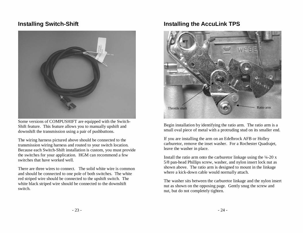
Throttle shaft Ratio arm
Begin installation by identifying the ratio arm. The ratio arm is a small oval piece of metal with a protruding stud on its smaller end.
If you are installing the arm on an Edelbrock AFB or Holley carburetor, remove the inset washer. For a Rochester Quadrajet, leave the washer in place.
Install the ratio arm onto the carburetor linkage using the ¼-20 x 5/8 pan-head Phillips screw, washer, and nylon insert lock nut as shown above. The ratio arm is designed to mount in the linkage where a kick-down cable would normally attach.
The washer sits between the carburetor linkage and the nylon insert nut as shown on the opposing page. Gently snug the screw and nut, but do not completely tighten.
- 25 -
Throttle
Screw
Ratio arm
Washer
Nut
- 26 -
Aligning the Ratio Arm for Edelbrock AFB and Holley Carburetors
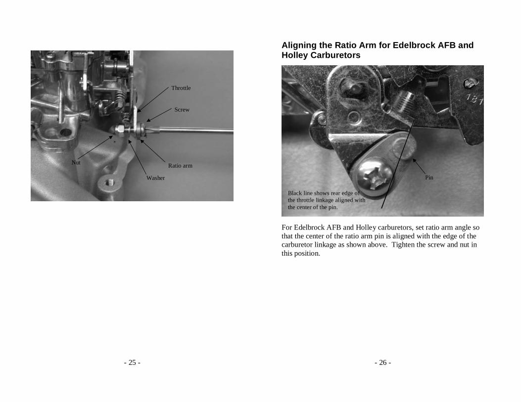
Pin
Black line shows rear edge of the throttle linkage aligned with the center of the pin.
For Edelbrock AFB and Holley carburetors, set ratio arm angle so that the center of the ratio arm pin is aligned with the edge of the carburetor linkage as shown above. Tighten the screw and nut in this position.
- 27 -
Aligning the Ratio Arm for Rochester Quadrajet Carburetors
For the Rochester Quadrajet, set the ratio arm angle so that the ratio arm pin is vertical as shown in the picture above. Tighten the screw and nut in this position.
- 28 -
Assembling the TPS Bracket
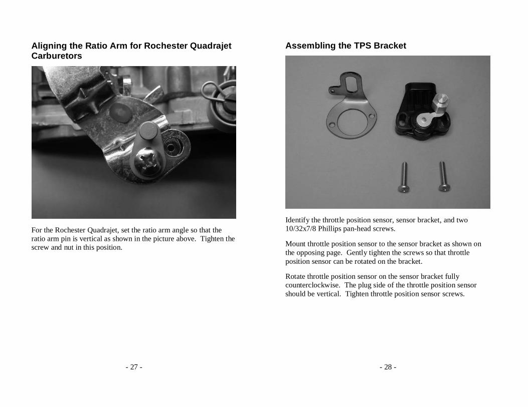
Identify the throttle position sensor, sensor bracket, and two 10/32x7/8 Phillips pan-head screws.
Mount throttle position sensor to the sensor bracket as shown on the opposing page. Gently tighten the screws so that throttle position sensor can be rotated on the bracket.
Rotate throttle position sensor on the sensor bracket fully counterclockwise. The plug side of the throttle position sensor should be vertical. Tighten throttle position sensor screws.
- 29 -
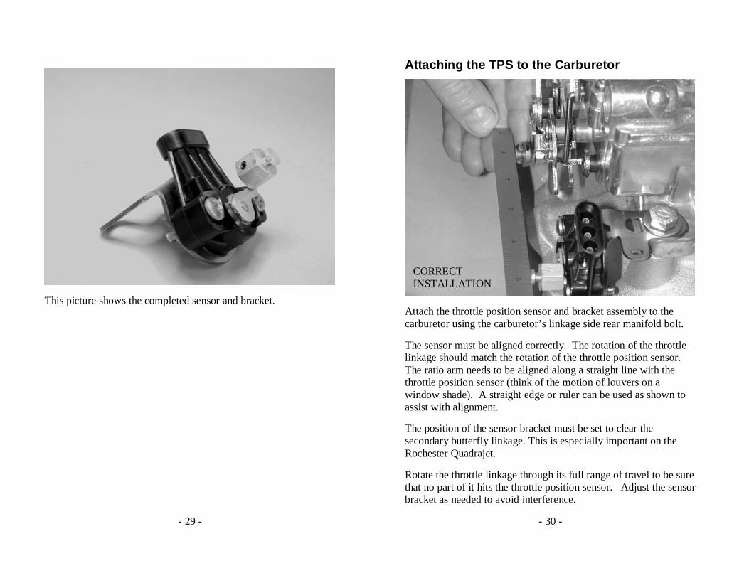
This picture shows the completed sensor and bracket.
- 30 -
Attaching the TPS to the Carburetor
CORRECT INSTALLATION
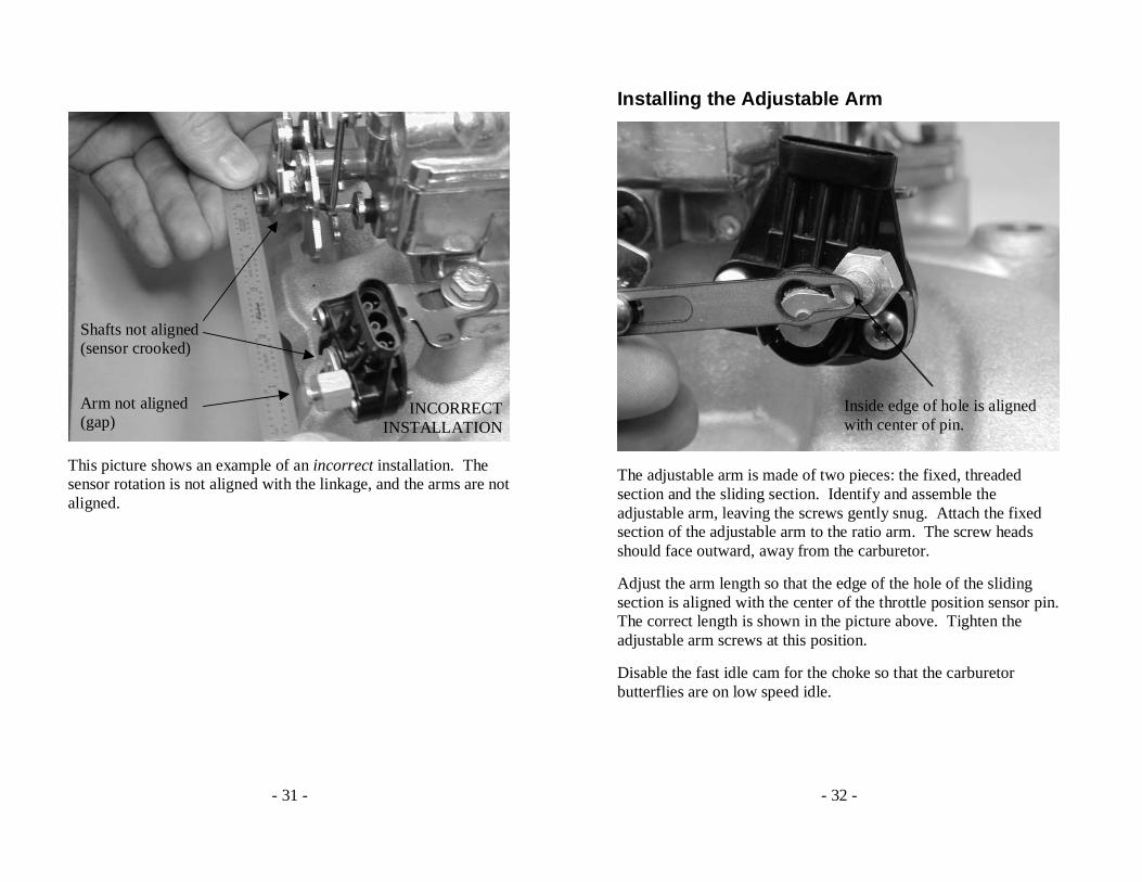
Attach the throttle position sensor and bracket assembly to the carburetor using the carburetor’s linkage side rear manifold bolt.
The sensor must be aligned correctly. The rotation of the throttle linkage should match the rotation of the throttle position sensor. The ratio arm needs to be aligned along a straight line with the throttle position sensor (think of the motion of louvers on a window shade). A straight edge or ruler can be used as shown to assist with alignment.
The position of the sensor bracket must be set to clear the secondary butterfly linkage. This is especially important on the Rochester Quadrajet.
Rotate the throttle linkage through its full range of travel to be sure that no part of it hits the throttle position sensor. Adjust the sensor bracket as needed to avoid interference.
- 31 -
Shafts not aligned (sensor crooked)
Arm not aligned (gap)
INCORRECT INSTALLATION
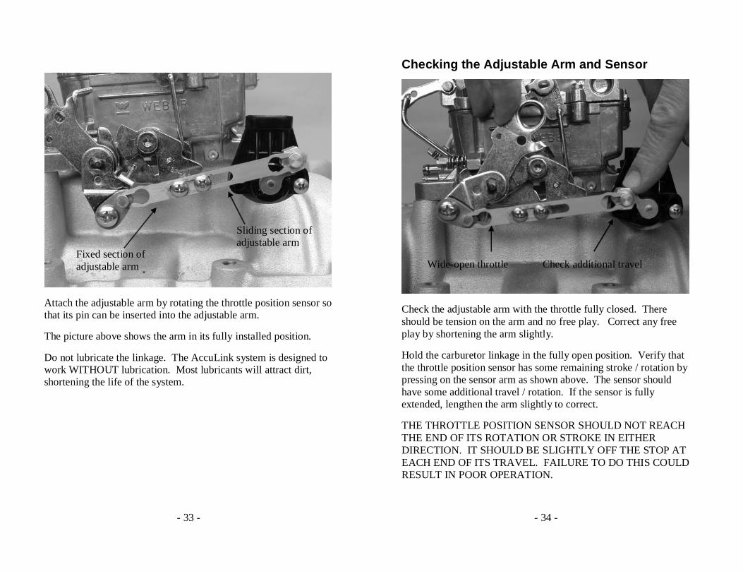
This picture shows an example of an incorrect installation. The sensor rotation is not aligned with the linkage, and the arms are not aligned.
- 32 -
Installing the Adjustable Arm
Inside edge of hole is aligned with center of pin.
The adjustable arm is made of two pieces: the fixed, threaded section and the sliding section. Identify and assemble the adjustable arm, leaving the screws gently snug. Attach the fixed section of the adjustable arm to the ratio arm. The screw heads should face outward, away from the carburetor.
Adjust the arm length so that the edge of the hole of the sliding section is aligned with the center of the throttle position sensor pin. The correct length is shown in the picture above. Tighten the adjustable arm screws at this position.
Disable the fast idle cam for the choke so that the carburetor butterflies are on low speed idle.
- 33 -
Fixed section of adjustable arm
Sliding section of adjustable arm
Attach the adjustable arm by rotating the throttle position sensor so that its pin can be inserted into the adjustable arm.
The picture above shows the arm in its fully installed position.
Do not lubricate the linkage. The AccuLink system is designed to work WITHOUT lubrication. Most lubricants will attract dirt, shortening the life of the system.
- 34 -
Checking the Adjustable Arm and Sensor
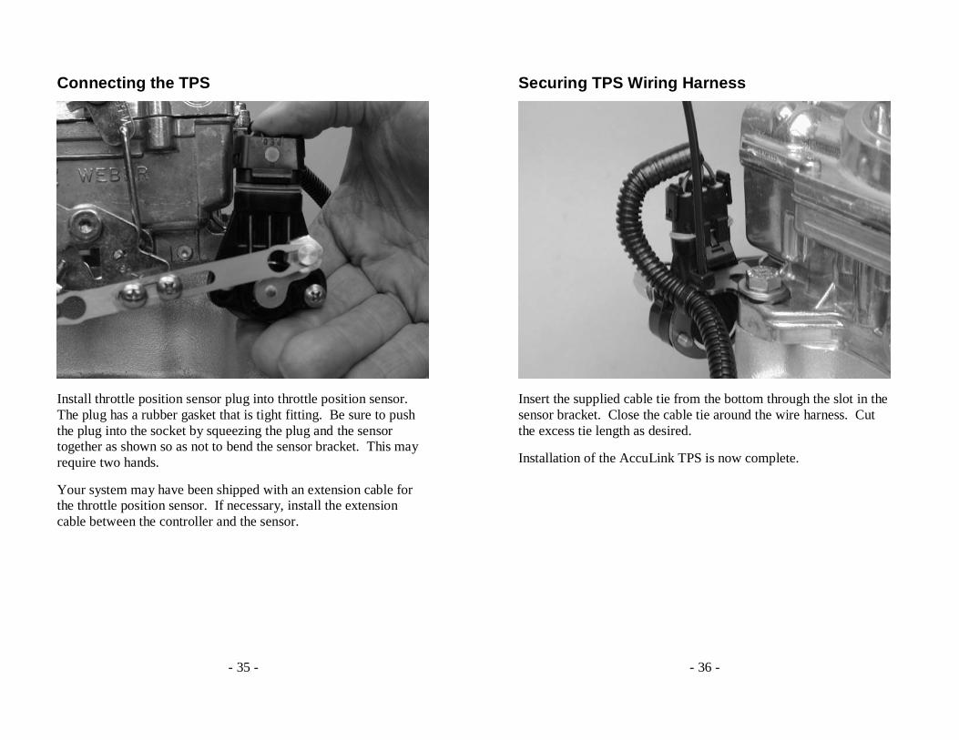
Wide-open throttle Check additional travel
Check the adjustable arm with the throttle fully closed. There should be tension on the arm and no free play. Correct any free play by shortening the arm slightly.
Hold the carburetor linkage in the fully open position. Verify that the throttle position sensor has some remaining stroke / rotation by pressing on the sensor arm as shown above. The sensor should have some additional travel / rotation. If the sensor is fully extended, lengthen the arm slightly to correct.
THE THROTTLE POSITION SENSOR SHOULD NOT REACH THE END OF ITS ROTATION OR STROKE IN EITHER DIRECTION. IT SHOULD BE SLIGHTLY OFF THE STOP AT EACH END OF ITS TRAVEL. FAILURE TO DO THIS COULD RESULT IN POOR OPERATION.
- 35 -
Connecting the TPS
Install throttle position sensor plug into throttle position sensor. The plug has a rubber gasket that is tight fitting. Be sure to push the plug into the socket by squeezing the plug and the sensor together as shown so as not to bend the sensor bracket. This may require two hands.
Your system may have been shipped with an extension cable for the throttle position sensor. If necessary, install the extension cable between the controller and the sensor.
- 36 -
Securing TPS Wiring Harness
Insert the supplied cable tie from the bottom through the slot in the sensor bracket. Close the cable tie around the wire harness. Cut the excess tie length as desired.
Installation of the AccuLink TPS is now complete.

- 37 -
Installing the Cable Throttle Position Sensor
Cable end
Ratio arm Cable bracket
Identify the ratio arm and attach it to the throttle linkage at an appropriate point using the supplied screw, washer and locking nut. The adjustable cable end attaches to the ratio arm.
The arm must be attached so that the cable moves about ¾” through the full throttle travel. The end of the ratio arm should be positioned about ¾” down from the throttle plate shaft in order to obtain correct travel. The travel should start from the closed throttle position with the cable arm pointing at a 45-degree angle to the direction of cable travel.
The drawing on the following page shows typical installation on a carburetor.
- 38 -

- 39 -
Mounting the Cable Bracket
The cable housing should be mounted with the supplied bracket near the throttle linkage as necessary. As shown in the previous drawing, the cable should be horizontal and level when attached to the ratio arm.
Both the cable housing and cable end have adjustable travel. Adjust the cable end by loosening the screw and then retightening it after moving the end to a new position.
The cable housing adjustment has a lock / unlock feature. Unlock the cable adjustment by pressing on the square button on the cable housing. Slide the cable housing as necessary. Lock by pressing the button on the opposite side.
- 40 -
The cable is spring loaded in the sensor box. You should be sure that the cable has some preload in the closed throttle position. You can adjust the preload by loosening the cable-end screw and taking up the slack.
Pictured above is the interior of the sensor box. You must not overextend the range of travel of the throttle position sensor. Doing so will break the sensor and void your warranty.
- 41 -
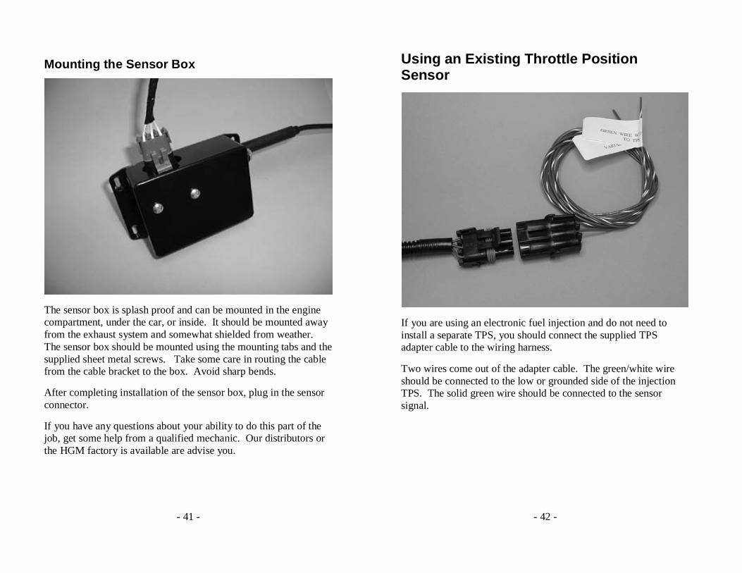
Mounting the Sensor Box
The sensor box is splash proof and can be mounted in the engine compartment, under the car, or inside. It should be mounted away from the exhaust system and somewhat shielded from weather. The sensor box should be mounted using the mounting tabs and the supplied sheet metal screws. Take some care in routing the cable from the cable bracket to the box. Avoid sharp bends.
After completing installation of the sensor box, plug in the sensor connector.
If you have any questions about your ability to do this part of the job, get some help from a qualified mechanic. Our distributors or the HGM factory is available are advise you.
- 42 -
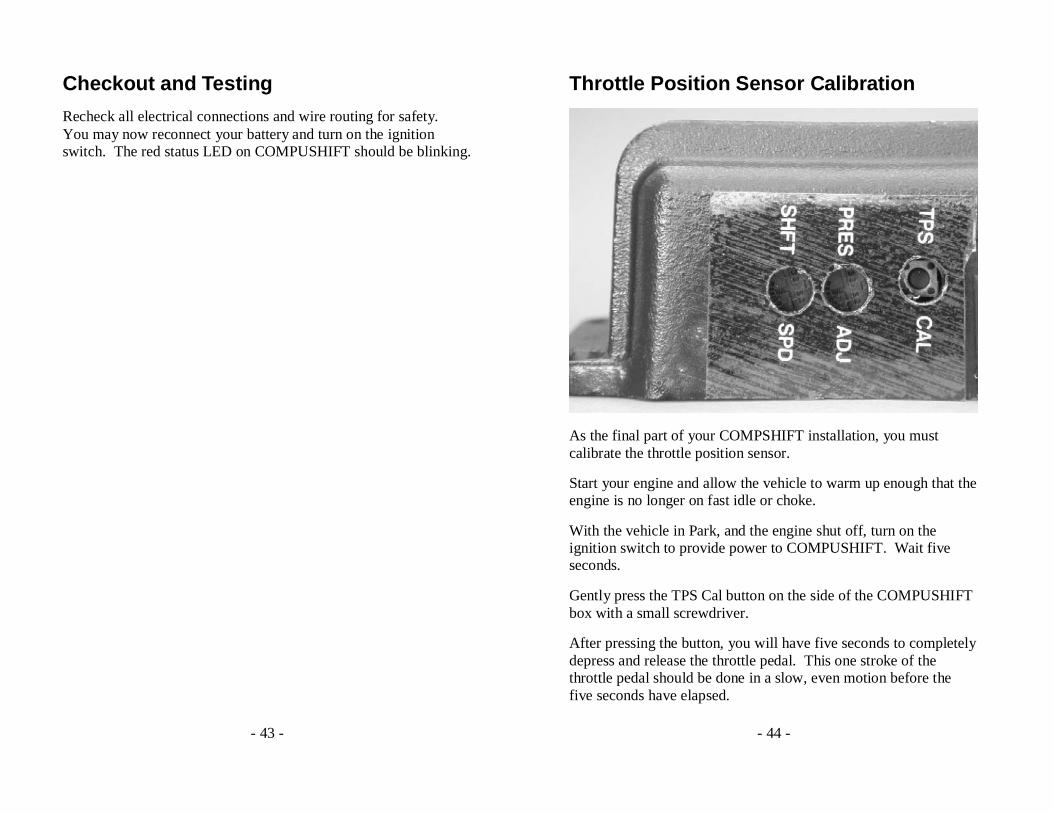
Using an Existing Throttle Position Sensor
If you are using an electronic fuel injection and do not need to install a separate TPS, you should connect the supplied TPS adapter cable to the wiring harness.
Two wires come out of the adapter cable. The green/white wire should be connected to the low or grounded side of the injection TPS. The solid green wire should be connected to the sensor signal.
- 43 -
Checkout and Testing
Recheck all electrical connections and wire routing for safety. You may now reconnect your battery and turn on the ignition switch. The red status LED on COMPUSHIFT should be blinking.
- 44 -
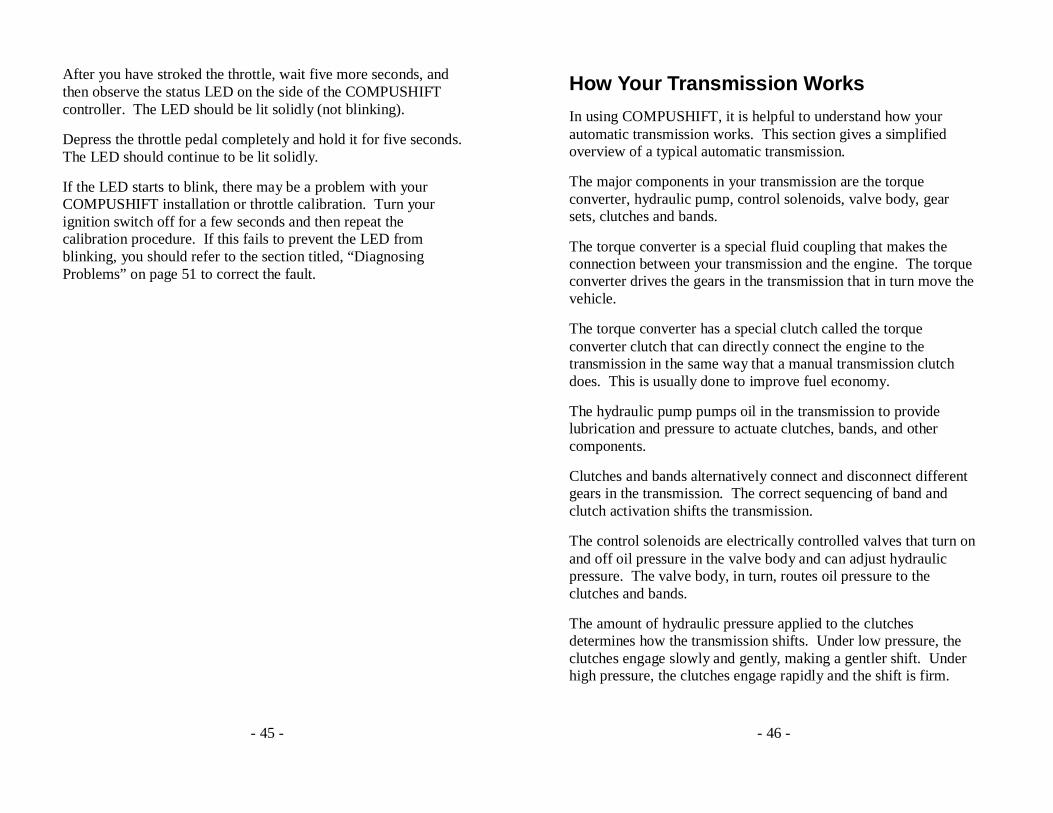
Throttle Position Sensor Calibration
As the final part of your COMPSHIFT installation, you must calibrate the throttle position sensor.
Start your engine and allow the vehicle to warm up enough that the engine is no longer on fast idle or choke.
With the vehicle in Park, and the engine shut off, turn on the ignition switch to provide power to COMPUSHIFT. Wait five seconds.
Gently press the TPS Cal button on the side of the COMPUSHIFT box with a small screwdriver.
After pressing the button, you will have five seconds to completely depress and release the throttle pedal. This one stroke of the throttle pedal should be done in a slow, even motion before the five seconds have elapsed.
- 45 -
After you have stroked the throttle, wait five more seconds, and then observe the status LED on the side of the COMPUSHIFT controller. The LED should be lit solidly (not blinking).
Depress the throttle pedal completely and hold it for five seconds. The LED should continue to be lit solidly.
If the LED starts to blink, there may be a problem with your COMPUSHIFT installation or throttle calibration. Turn your ignition switch off for a few seconds and then repeat the calibration procedure. If this fails to prevent the LED from blinking, you should refer to the section titled, “Diagnosing Problems” on page 51 to correct the fault.
- 46 -
How Your Transmission Works
In using COMPUSHIFT, it is helpful to understand how your automatic transmission works. This section gives a simplified overview of a typical automatic transmission.
The major components in your transmission are the torque converter, hydraulic pump, control solenoids, valve body, gear sets, clutches and bands.
The torque converter is a special fluid coupling that makes the connection between your transmission and the engine. The torque converter drives the gears in the transmission that in turn move the vehicle.
The torque converter has a special clutch called the torque converter clutch that can directly connect the engine to the transmission in the same way that a manual transmission clutch does. This is usually done to improve fuel economy.
The hydraulic pump pumps oil in the transmission to provide lubrication and pressure to actuate clutches, bands, and other components.
Clutches and bands alternatively connect and disconnect different gears in the transmission. The correct sequencing of band and clutch activation shifts the transmission.
The control solenoids are electrically controlled valves that turn on and off oil pressure in the valve body and can adjust hydraulic pressure. The valve body, in turn, routes oil pressure to the clutches and bands.
The amount of hydraulic pressure applied to the clutches determines how the transmission shifts. Under low pressure, the clutches engage slowly and gently, making a gentler shift. Under high pressure, the clutches engage rapidly and the shift is firm.
- 47 -
It is important that the shift pressure be adjusted according to the transmission load conditions. If the transmission shifts gently while the engine produces high torque, the transmission clutches will slip. This will eventually burn out the clutches.
Conversely, if the transmission shifts firmly all of the time, the clutches and drive train will be subjected to unnecessary stress. This could be unpleasant for the driver and passengers, too.
The best programming of shift pressure provides the correct pressure during all driving circumstances. Your COMPUSHIFT can be programmed to deliver neck-jerking shifts under full throttle, but have smooth drivability during light throttle and cruising.
It is important to understand that not all aspects of shifting can be controlled by COMPUSHIFT. The specifics of how the transmission is built make a tremendous difference in how it reacts to the control by COMPUSHIFT. Identical COMPUSHIFT controllers will have different shift properties on differently built transmissions. We recommend that you consult with a qualified transmission builder to achieve the exact shifting characteristics you want.
- 48 -
Driving with COMPUSHIFT
COMPUSHIFT uses information about the throttle position, vehicle speed and the gear level to decide when to shift. As you increase the amount applied throttle, COMPUSHIFT decides to upshift at increasingly higher vehicle speeds. When you drive away with light throttle, COMPUSHIFT upshifts relatively soon. If you give the engine full throttle, COMPUSHIFT will upshift at a high vehicle speed and engine RPM.
Shift firmness is controlled in the much the same way as shift speed. Shift firmness is related to throttle position, not vehicle speed. This is because a firm shift is required to prevent slippage when the engine is making more torque. Under less power, the shift can be gentler.
- 49 -
Adjusting COMPUSHIFT
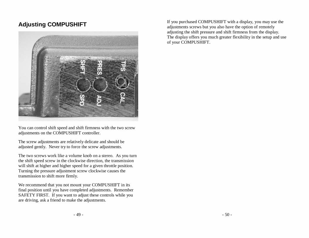
You can control shift speed and shift firmness with the two screw adjustments on the COMPUSHIFT controller.
The screw adjustments are relatively delicate and should be adjusted gently. Never try to force the screw adjustments.
The two screws work like a volume knob on a stereo. As you turn the shift speed screw in the clockwise direction, the transmission will shift at higher and higher speed for a given throttle position. Turning the pressure adjustment screw clockwise causes the transmission to shift more firmly.
We recommend that you not mount your COMPUSHIFT in its final position until you have completed adjustments. Remember SAFETY FIRST. If you want to adjust these controls while you are driving, ask a friend to make the adjustments.
- 50 -
If you purchased COMPUSHIFT with a display, you may use the adjustments screws but you also have the option of remotely adjusting the shift pressure and shift firmness from the display. The display offers you much greater flexibility in the setup and use of your COMPUSHIFT.
- 51 -
Diagnosing Problems
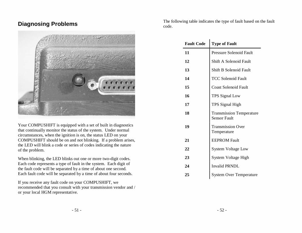
Your COMPUSHIFT is equipped with a set of built in diagnostics that continually monitor the status of the system. Under normal circumstances, when the ignition is on, the status LED on your COMPUSHIFT should be on and not blinking. If a problem arises, the LED will blink a code or series of codes indicating the nature of the problem.
When blinking, the LED blinks out one or more two-digit codes. Each code represents a type of fault in the system. Each digit of the fault code will be separated by a time of about one second. Each fault code will be separated by a time of about four seconds.
If you receive any fault code on your COMPUSHIFT, we recommended that you consult with your transmission vendor and / or your local HGM representative.
- 52 -
The following table indicates the type of fault based on the fault code.
Fault Code Type of Fault
11 Pressure Solenoid Fault
12 Shift A Solenoid Fault
13 Shift B Solenoid Fault
14 TCC Solenoid Fault
15 Coast Solenoid Fault
16 TPS Signal Low
17 TPS Signal High
18 Transmission Temperature Sensor Fault
19 Transmission Over Temperature
21 EEPROM Fault
22 System Voltage Low
23 System Voltage High
24 Invalid PRNDL
25 System Over Temperature
- 53 -
Pressure Solenoid Fault, Shift A Solenoid Fault, Shift B Solenoid Fault, TCC Solenoid Fault, Coast Clutch Solenoid Fault
These faults indicate a problem with a control solenoid in your transmission. Your COMPUSHIFT can detect an open circuit or short circuit on the solenoid circuits. It will signal any of these conditions by setting the appropriate fault for the solenoid circuit. COMPUSHIFT may also temporarily disconnect that solenoid from the circuit.
TPS Signal Low
This fault indicates that a TPS signal less than that allowed by the current calibration has been received. This can indicate faulty wiring, incorrect calibration, or a faulty TPS. In some cases, this can also be caused by cable slippage or an incorrect initial calibration. Repeat the calibration procedure before attempting other diagnostics.
TPS Signal High
This fault indicates that a TPS signal greater than that allowed by the current calibration has been received. This can indicate bad wiring, incorrect calibration, or a faulty TPS. This can also be caused by an incorrect initial calibration. Repeat the calibration procedure before attempting other diagnostics.
Both TPS Signal High and TPS Signal Low
If both the TPS Signal High and TPS Signal Low codes are indicated immediately after power is applied to COMPUSHIFT, this indicates that there is no valid calibration for the TPS. You must calibrate the TPS following the instructions on page 44. The TPS sensor must move through at least a quarter of its full stroke to calibrate properly.
- 54 -
COMPUSHIFT generally comes from the factory without TPS calibration, so these codes will be indicated before the first calibration. These codes will also be indicated before calibration if COMPUSHIFT is reset to factory defaults using the optional display.
As a failsafe, when the TPS is not calibrated COMPUSHIFT uses a constant value of 50% throttle.
Transmission Temperature Sensor Fault
This fault indicates that COMPUSHIFT has received a temperature signal from the transmission that is out of the possible operating range of the sensor. This fault usually indicates that the sensor has failed, or that the wiring to the sensor is faulty. In order to preserve shift quality, COMPUSHIFT must have an accurate measurement of your transmission’s temperature.
Transmission Over Temperature
This fault indicates that your transmission is running too hot. You should discontinue using your vehicle as soon as possible as transmission damage is imminent. This fault is triggered when transmission temperature exceeds 275°F / 135°C for 10 seconds or more.
EEPROM Fault
This fault indicates that the internal memory system of your COMPUSHIFT has suffered a failure. Contact HGM Automotive Electronics for repair or replacement of your controller.
System Voltage Low
This fault indicates that COMPUSHIFT has detected that the 12-volt power supply has dropped too low for an extended period. If you have an indication of this fault, make sure that your
- 55 -
COMPUSHIFT has a good connection to 12-volt power and ground, and that your battery is fully charged.
System Voltage High
This fault indicates that COMPUSHIFT has detected that the 12-volt power supply has exceeded the normal operating range. This condition can damage to COMPUSHIFT and other components in your vehicle. This fault usually indicates a failure of the vehicle charging system. Do not disconnect your battery while the vehicle engine is running. Doing so could damage COMPUSHIFT and any other vehicle electronics.
Invalid PRNDL
This fault indicates that an invalid signal combination has been received from the transmission gear selector (PRNDL) switch. Faulty wiring, a failed switch, or a hydraulic problem in the transmission can cause this.
System Over Temperature
This fault indicates that the internal temperature of COMPUSHIFT has exceeded a safe range. COMPUSHIFT will automatically turn itself off 25 seconds after this fault is displayed. The status LED will go dark. This fault can occur if a partial short exists in the transmission wiring, or if COMPUSHIFT is overheated due to improper mounting.
- 56 -
Driving with Switch-Shift
Switch-Shift mode lets you use both the shift lever and a pair of pushbutton switches to control the transmission gear.
In Switch-Shift mode, the transmission normally shifts automatically. Pressing either the upshift or downshift button will change the transmission gear and hold the new gear as long as there is some throttle applied. As soon as the throttle is released, the transmission will revert to automatic shifts. The system will prevent shifts that would overrev the engine.
At a stop, the transmission is normally in first gear. If you press the downshift button, the transmission will stay in first gear, but will be in switch-shift mode. Pressing the upshift button at a stop will shift into second gear to allow a second gear start.
Changing the shift level will automatically exit switch-shift mode and Compushift will revert to automatic mode.
Many transmissions do not have the ability to engine brake under automatic control. This means that you cannot control your speed on a descent using the switch-shift controls. If you wish to use engine while decelerating, you must use the shift lever.

- 57 -
The COMPUSHIFT Display
The COMPSHIFT display has a 20 x 4 character backlit liquid crystal display (LCD) and a four key keypad. The display is connected to the main COMPSHIFT controller by standard four-position telephone cable (included). If you need to mount the display some distance from the controller, you can purchase a longer cable, provided the length does not exceed 25 feet.
DO NOT CONNECT ANYTHING OTHER THAN YOUR DISPLAY TO YOUR COMPUSHIFT CONTROLLER. DO NOT CONNECT ANYTHING OTHER THAN YOUR COMPUSHIFT CONTROLLER TO THE DISPLAY. DOING SO CAN DAMAGE YOUR DISPLAY, YOUR COMPUSHIFT CONTROLLER OR BOTH AND WILL VOID YOUR WARANTY. DO NOT CONNECT TO A TELEPHONE LINE.
The rear of the display box has a pair of threaded inserts that allow you mount the display.
- 58 -
The display operates in two different modes, each of which has a group of different screens. These modes are the SETUP mode and the METER mode.
The METER screens are available when you are driving and show you information about your transmission, COMPUSHIFT and your vehicle.
The SETUP screens are available when your vehicle is stopped, the engine is off, and the ignition switch is on.
SETUP allows you to change the programming of your controller. When COMPUSHIFT is in the SETUP mode, control of the transmission is disabled. You should never try to enter SETUP mode while you are driving. SETUP is covered further in the next section.
The system can display information in US standard or metric units. The choice is available in the SETUP mode.
- 59 -
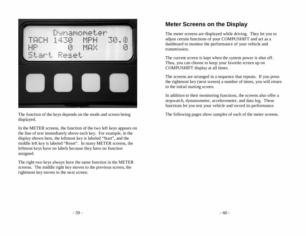
The function of the keys depends on the mode and screen being displayed.
In the METER screens, the function of the two left keys appears on the line of text immediately above each key. For example, in the display shown here, the leftmost key is labeled “Start”, and the middle left key is labeled “Reset”. In many METER screens, the leftmost keys have no labels because they have no function assigned.
The right two keys always have the same function in the METER screens. The middle right key moves to the previous screen, the rightmost key moves to the next screen.
- 60 -
Meter Screens on the Display
The meter screens are displayed while driving. They let you to adjust certain functions of your COMPUSHIFT and act as a dashboard to monitor the performance of your vehicle and transmission.
The current screen is kept when the system power is shut off. Thus, you can choose to keep your favorite screen up on COMPUSHIFT display at all times.
The screens are arranged in a sequence that repeats. If you press the rightmost key (next screen) a number of times, you will return to the initial starting screen.
In addition to their monitoring functions, the screens also offer a stopwatch, dynamometer, accelerometer, and data log. These functions let you test your vehicle and record its performance.
The following pages show samples of each of the meter screens.
- 61 -
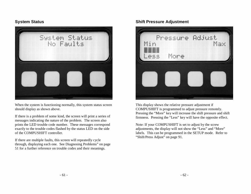
System Status
When the system is functioning normally, this system status screen should display as shown above.
If there is a problem of some kind, the screen will print a series of messages indicating the nature of the problem. The screen also prints the LED trouble code number. These messages correspond exactly to the trouble codes flashed by the status LED on the side of the COMPUSHIFT controller.
If there are multiple faults, this screen will repeatedly cycle through, displaying each one. See Diagnosing Problems” on page 51 for a further reference on trouble codes and their meanings.
- 62 -
Shift Pressure Adjustment
This display shows the relative pressure adjustment if COMPUSHIFT is programmed to adjust pressure remotely. Pressing the “More” key will increase the shift pressure and shift firmness. Pressing the “Less” key will have the opposite effect.
Note: If your COMPUSHIFT is set to adjust by the screw adjustments, the display will not show the “Less” and “More” labels. This can be programmed in the SETUP mode. Refer to “Shift/Press Adjust” on page 91.

- 63 -
Shift Speed Adjustment
This display shows the relative shift speed adjustment if COMPUSHIFT is programmed to adjust shift speed remotely. Pressing the “More” key will increase the shift speed. Pressing the “Less” key will have the opposite effect.
Note: If your COMPUSHIFT is set to adjust by the screw adjustments, the display will not show the “Less” and “More” labels. This can be programmed in the SETUP mode. Refer to “Shift/Press Adjust” on page 91.
- 64 -
Mixed Meter Display
Your COMPSHIFT offers a display mode that presents a group of information on a single screen. This information is displayed in two columns of four meters as shown in the following table:
- 65 -
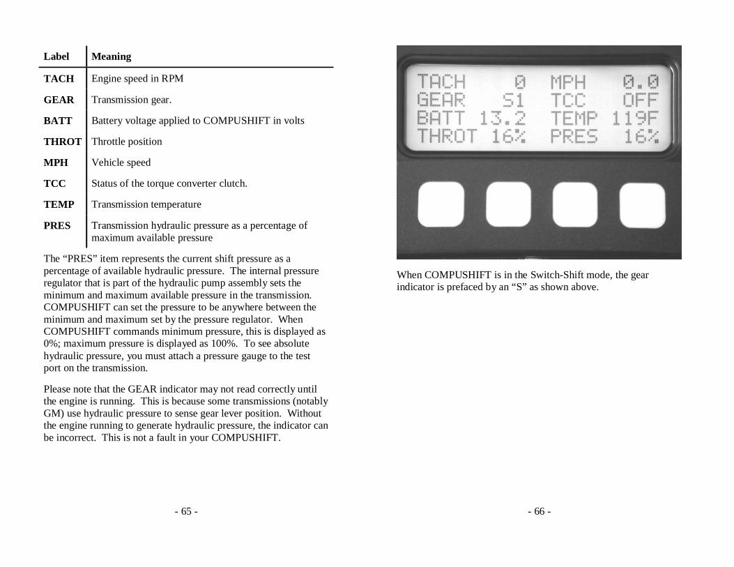
Label Meaning
TACH Engine speed in RPM
GEAR Transmission gear.
BATT Battery voltage applied to COMPUSHIFT in volts
THROT Throttle position
MPH Vehicle speed
TCC Status of the torque converter clutch.
TEMP Transmission temperature
PRES Transmission hydraulic pressure as a percentage of maximum available pressure
The “PRES” item represents the current shift pressure as a percentage of available hydraulic pressure. The internal pressure regulator that is part of the hydraulic pump assembly sets the minimum and maximum available pressure in the transmission. COMPUSHIFT can set the pressure to be anywhere between the minimum and maximum set by the pressure regulator. When COMPUSHIFT commands minimum pressure, this is displayed as 0%; maximum pressure is displayed as 100%. To see absolute hydraulic pressure, you must attach a pressure gauge to the test port on the transmission.
Please note that the GEAR indicator may not read correctly until the engine is running. This is because some transmissions (notably GM) use hydraulic pressure to sense gear lever position. Without the engine running to generate hydraulic pressure, the indicator can be incorrect. This is not a fault in your COMPUSHIFT.
- 66 -
When COMPUSHIFT is in the Switch-Shift mode, the gear indicator is prefaced by an “S” as shown above.
- 67 -
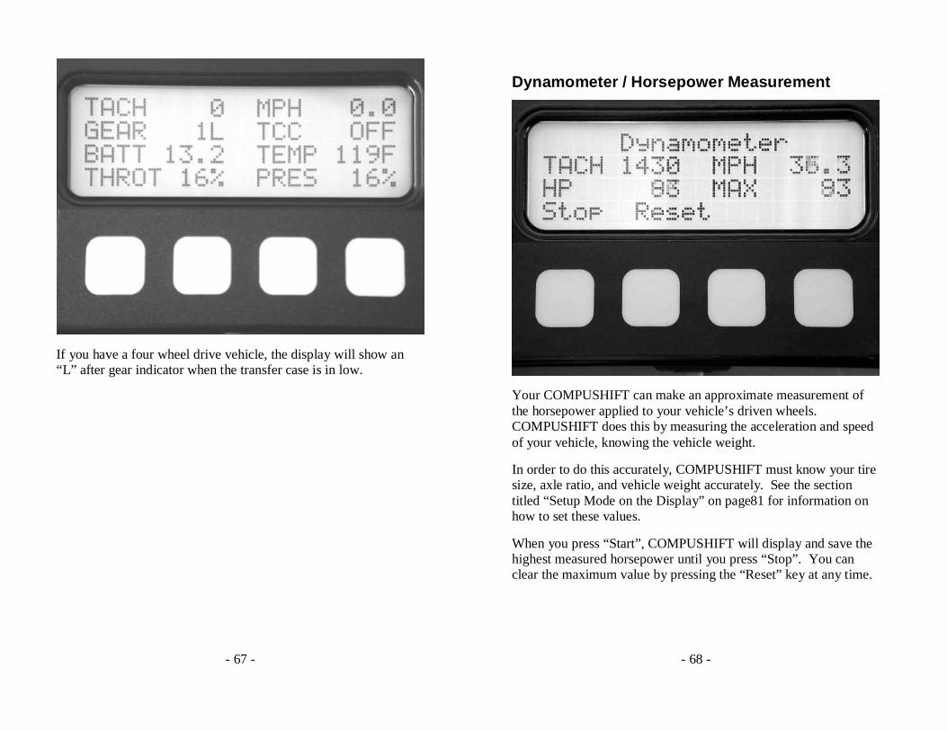
If you have a four wheel drive vehicle, the display will show an “L” after gear indicator when the transfer case is in low.
- 68 -
Dynamometer / Horsepower Measurement
Your COMPUSHIFT can make an approximate measurement of the horsepower applied to your vehicle’s driven wheels. COMPUSHIFT does this by measuring the acceleration and speed of your vehicle, knowing the vehicle weight.
In order to do this accurately, COMPUSHIFT must know your tire size, axle ratio, and vehicle weight accurately. See the section titled “Setup Mode on the Display” on page81 for information on how to set these values.
When you press “Start”, COMPUSHIFT will display and save the highest measured horsepower until you press “Stop”. You can clear the maximum value by pressing the “Reset” key at any time.
- 69 -
Avoid spinning your wheels during the measurement as this will give incorrect results. Remember SAFETY FIRST. This feature should not be used on public roads. This feature is intended as an approximate measurement for tuning purposes and is not designed to replace a chassis dynamometer.
- 70 -
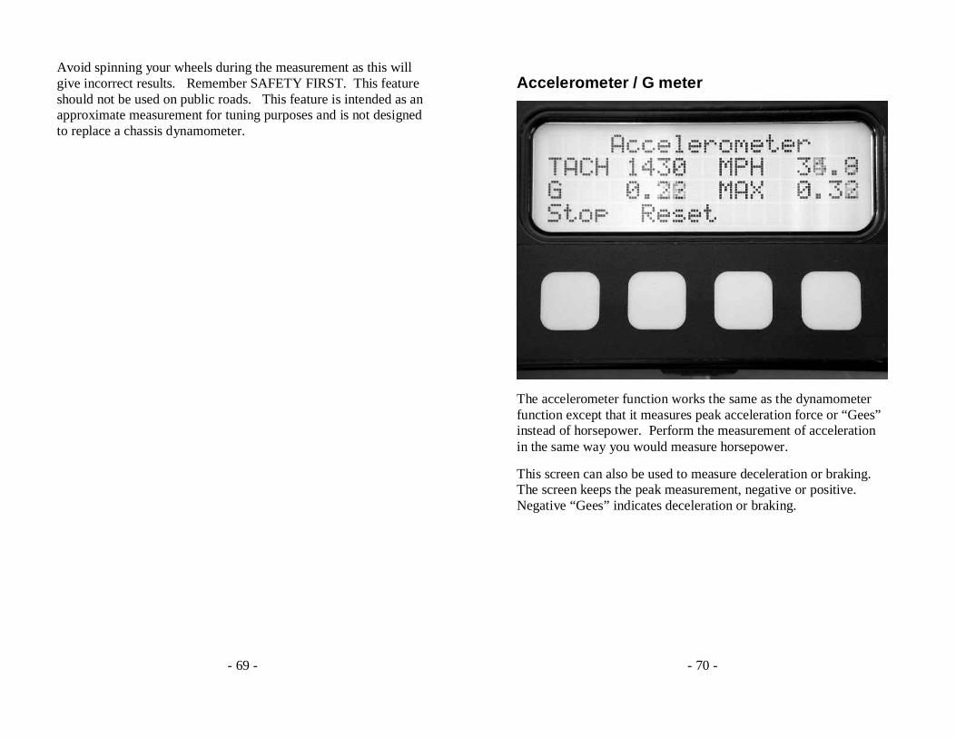
Accelerometer / G meter
The accelerometer function works the same as the dynamometer function except that it measures peak acceleration force or “Gees” instead of horsepower. Perform the measurement of acceleration in the same way you would measure horsepower.
This screen can also be used to measure deceleration or braking. The screen keeps the peak measurement, negative or positive. Negative “Gees” indicates deceleration or braking.
- 71 -
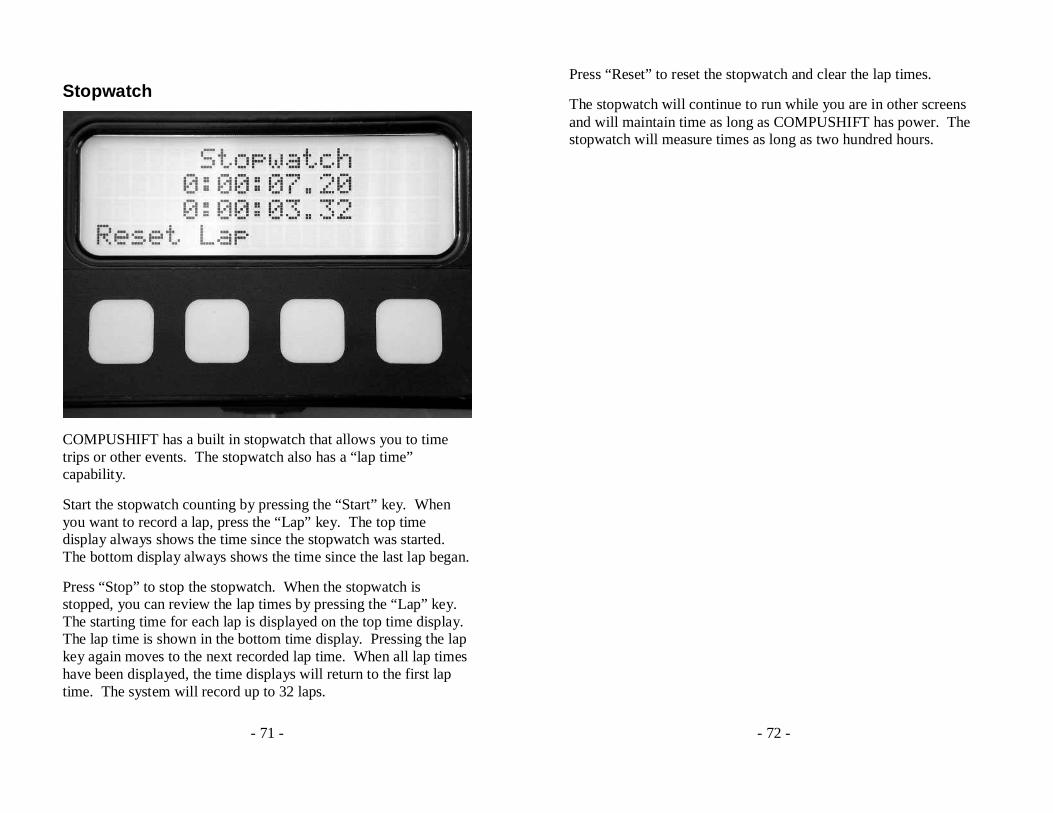
Stopwatch
COMPUSHIFT has a built in stopwatch that allows you to time trips or other events. The stopwatch also has a “lap time” capability.
Start the stopwatch counting by pressing the “Start” key. When you want to record a lap, press the “Lap” key. The top time display always shows the time since the stopwatch was started. The bottom display always shows the time since the last lap began.
Press “Stop” to stop the stopwatch. When the stopwatch is stopped, you can review the lap times by pressing the “Lap” key. The starting time for each lap is displayed on the top time display. The lap time is shown in the bottom time display. Pressing the lap key again moves to the next recorded lap time. When all lap times have been displayed, the time displays will return to the first lap time. The system will record up to 32 laps.
- 72 -
Press “Reset” to reset the stopwatch and clear the lap times.
The stopwatch will continue to run while you are in other screens and will maintain time as long as COMPUSHIFT has power. The stopwatch will measure times as long as two hundred hours.
- 73 -
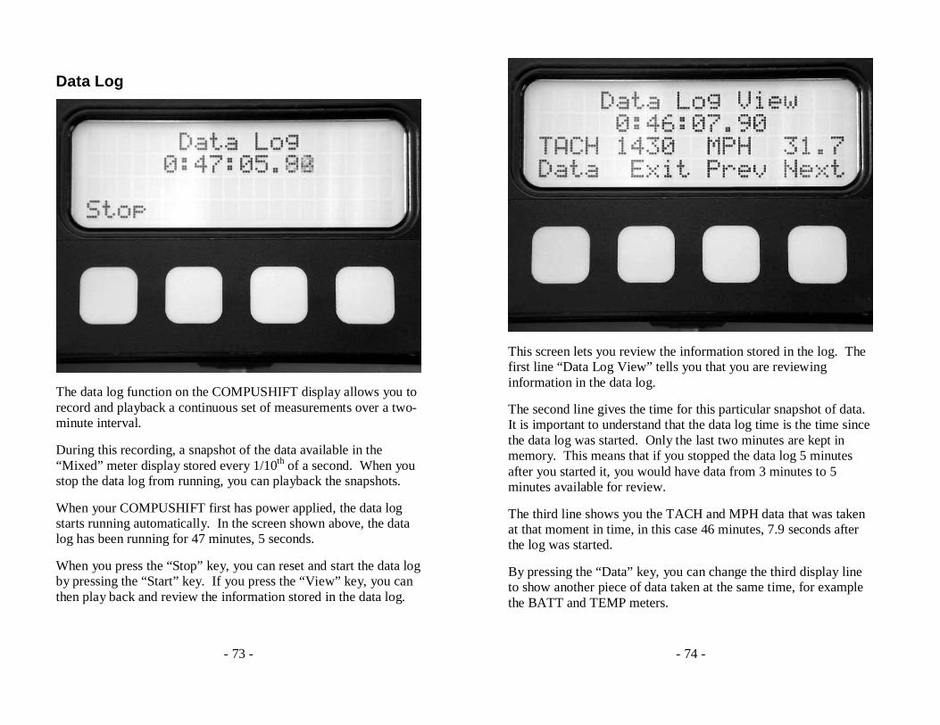
Data Log
The data log function on the COMPUSHIFT display allows you to record and playback a continuous set of measurements over a two-minute interval.
During this recording, a snapshot of the data available in the “Mixed” meter display stored every 1/10th of a second. When you stop the data log from running, you can playback the snapshots.
When your COMPUSHIFT first has power applied, the data log starts running automatically. In the screen shown above, the data log has been running for 47 minutes, 5 seconds.
When you press the “Stop” key, you can reset and start the data log by pressing the “Start” key. If you press the “View” key, you can then play back and review the information stored in the data log.
- 74 -
This screen lets you review the information stored in the log. The first line “Data Log View” tells you that you are reviewing information in the data log.
The second line gives the time for this particular snapshot of data. It is important to understand that the data log time is the time since the data log was started. Only the last two minutes are kept in memory. This means that if you stopped the data log 5 minutes after you started it, you would have data from 3 minutes to 5 minutes available for review.
The third line shows you the TACH and MPH data that was taken at that moment in time, in this case 46 minutes, 7.9 seconds after the log was started.
By pressing the “Data” key, you can change the third display line to show another piece of data taken at the same time, for example the BATT and TEMP meters.
- 75 -
The “Prev” and “Next” keys move forward and backward in the two minute time period that has been recorded.
The “Exit” key leaves the “Data Log View” mode and returns to the previous screen, allowing you to restart the data log if you choose.
As noted before, the data log begins running automatically when you power on your COMPUSHIFT. This means that data is available for your review even if you have not explicitly started the log.
Remember SAFETY FIRST. Stop and safely park your vehicle before reviewing data in the data log.
- 76 -
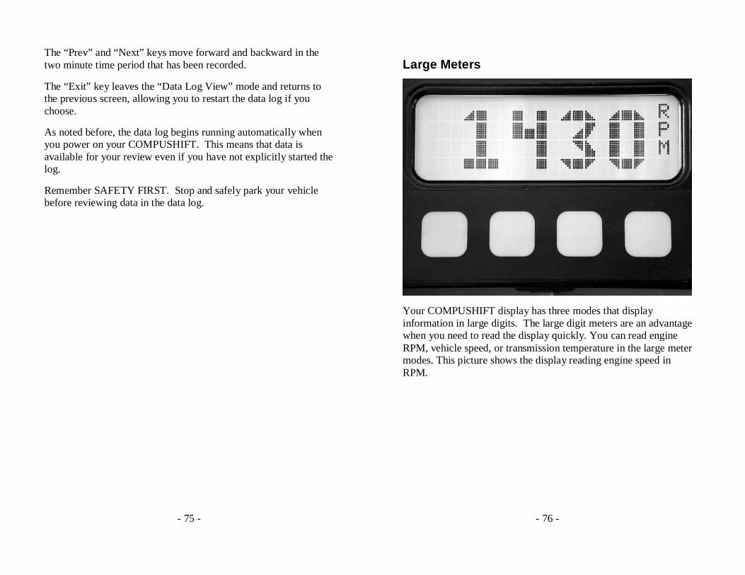
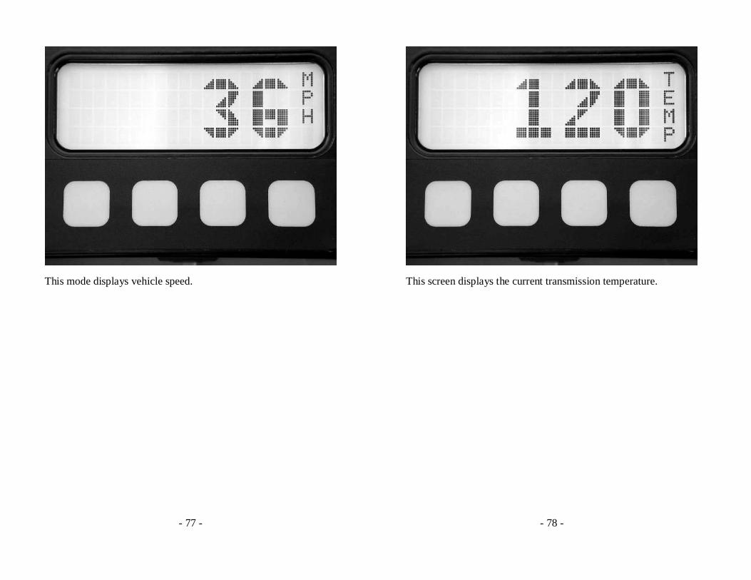
Large Meters
Your COMPUSHIFT display has three modes that display information in large digits. The large digit meters are an advantage when you need to read the display quickly. You can read engine RPM, vehicle speed, or transmission temperature in the large meter modes. This picture shows the display reading engine speed in RPM.
- 77 -
This mode displays vehicle speed.
- 78 -
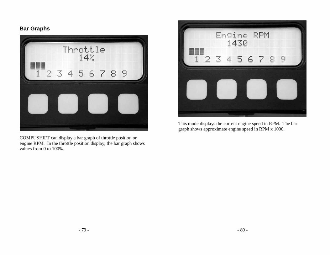
This screen displays the current transmission temperature.
- 79 -
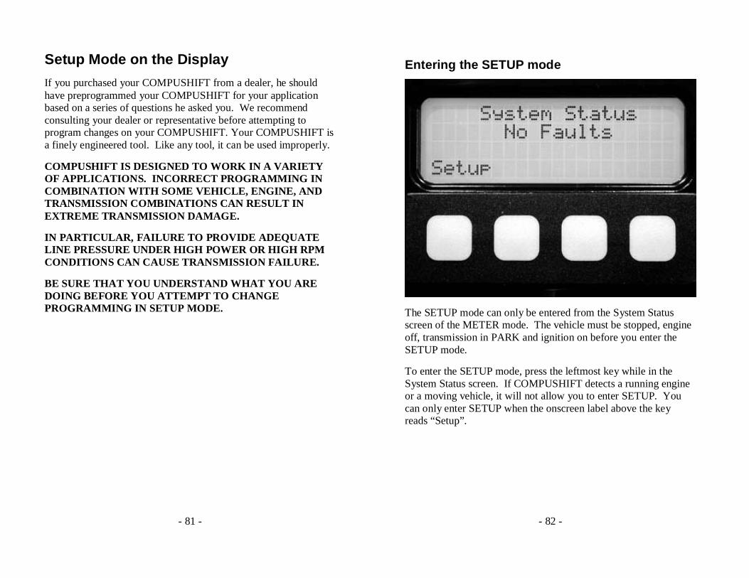
Bar Graphs
COMPUSHIFT can display a bar graph of throttle position or engine RPM. In the throttle position display, the bar graph shows values from 0 to 100%.
- 80 -
This mode displays the current engine speed in RPM. The bar graph shows approximate engine speed in RPM x 1000.
- 81 -
Setup Mode on the Display
If you purchased your COMPUSHIFT from a dealer, he should have preprogrammed your COMPUSHIFT for your application based on a series of questions he asked you. We recommend consulting your dealer or representative before attempting to program changes on your COMPUSHIFT. Your COMPUSHIFT is a finely engineered tool. Like any tool, it can be used improperly.
COMPUSHIFT IS DESIGNED TO WORK IN A VARIETY OF APPLICATIONS. INCORRECT PROGRAMMING IN COMBINATION WITH SOME VEHICLE, ENGINE, AND TRANSMISSION COMBINATIONS CAN RESULT IN EXTREME TRANSMISSION DAMAGE.
IN PARTICULAR, FAILURE TO PROVIDE ADEQUATE LINE PRESSURE UNDER HIGH POWER OR HIGH RPM CONDITIONS CAN CAUSE TRANSMISSION FAILURE.
BE SURE THAT YOU UNDERSTAND WHAT YOU ARE DOING BEFORE YOU ATTEMPT TO CHANGE PROGRAMMING IN SETUP MODE.
- 82 -
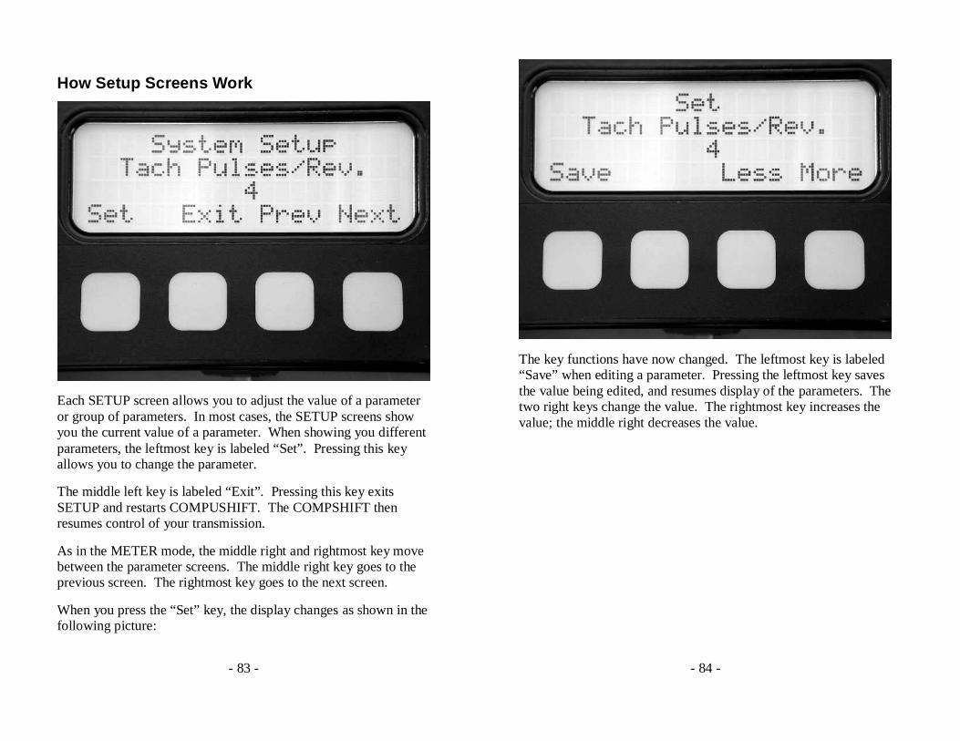
Entering the SETUP mode
The SETUP mode can only be entered from the System Status screen of the METER mode. The vehicle must be stopped, engine off, transmission in PARK and ignition on before you enter the SETUP mode.
To enter the SETUP mode, press the leftmost key while in the System Status screen. If COMPUSHIFT detects a running engine or a moving vehicle, it will not allow you to enter SETUP. You can only enter SETUP when the onscreen label above the key reads “Setup”.
- 83 -
How Setup Screens Work
Each SETUP screen allows you to adjust the value of a parameter or group of parameters. In most cases, the SETUP screens show you the current value of a parameter. When showing you different parameters, the leftmost key is labeled “Set”. Pressing this key allows you to change the parameter.
The middle left key is labeled “Exit”. Pressing this key exits SETUP and restarts COMPUSHIFT. The COMPSHIFT then resumes control of your transmission.
As in the METER mode, the middle right and rightmost key move between the parameter screens. The middle right key goes to the previous screen. The rightmost key goes to the next screen.
When you press the “Set” key, the display changes as shown in the following picture:
- 84 -
The key functions have now changed. The leftmost key is labeled “Save” when editing a parameter. Pressing the leftmost key saves the value being edited, and resumes display of the parameters. The two right keys change the value. The rightmost key increases the value; the middle right decreases the value.
- 85 -
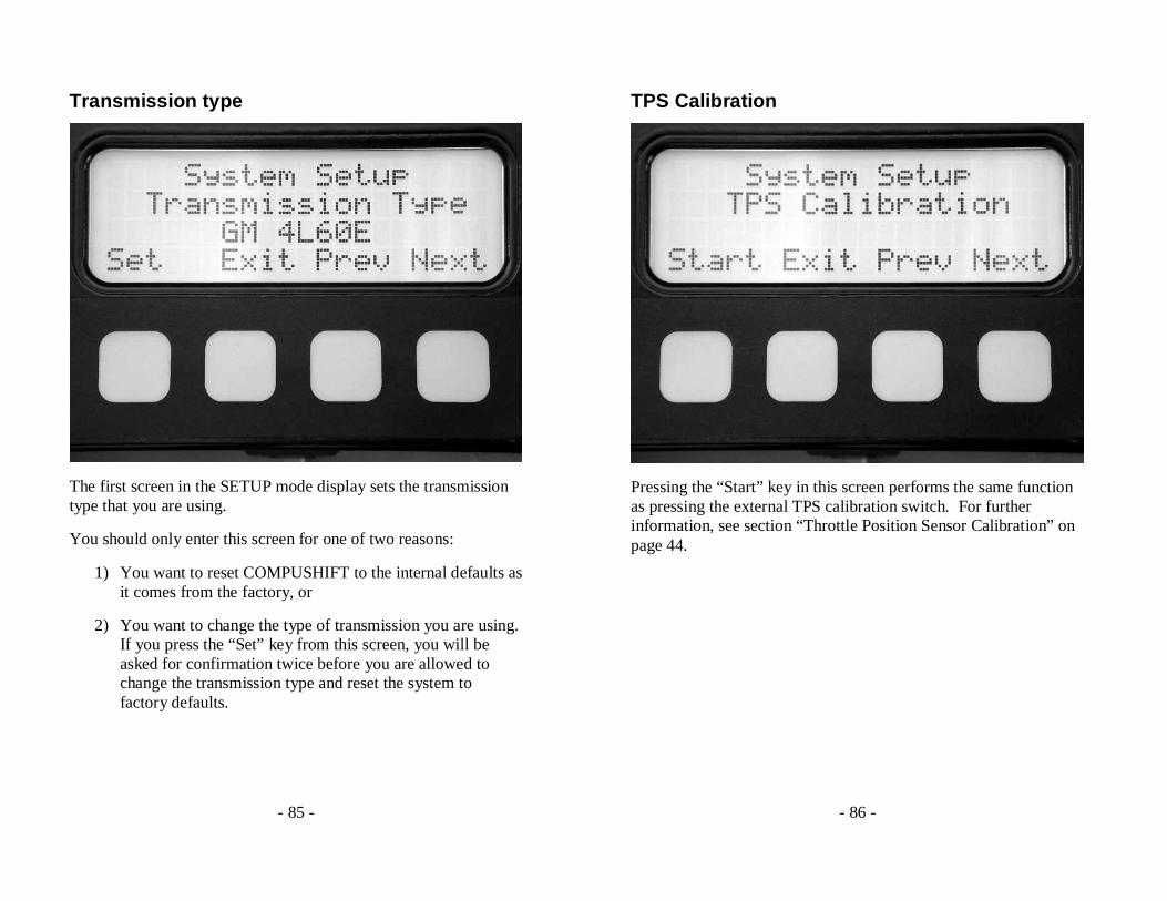
Transmission type
The first screen in the SETUP mode display sets the transmission type that you are using.
You should only enter this screen for one of two reasons:
1) You want to reset COMPUSHIFT to the internal defaults as it comes from the factory, or
2) You want to change the type of transmission you are using. If you press the “Set” key from this screen, you will be asked for confirmation twice before you are allowed to change the transmission type and reset the system to factory defaults.
- 86 -
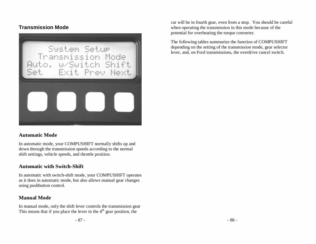
TPS Calibration
Pressing the “Start” key in this screen performs the same function as pressing the external TPS calibration switch. For further information, see section “Throttle Position Sensor Calibration” on page 44.
- 87 -
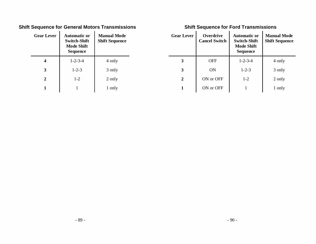
Transmission Mode
Automatic Mode
In automatic mode, your COMPUSHIFT normally shifts up and down through the transmission speeds according to the normal shift settings, vehicle speeds, and throttle position.
Automatic with Switch-Shift
In automatic with switch-shift mode, your COMPUSHIFT operates as it does in automatic mode, but also allows manual gear changes using pushbutton control.
Manual Mode
In manual mode, only the shift lever controls the transmission gear This means that if you place the lever in the 4th gear position, the
- 88 -
car will be in fourth gear, even from a stop. You should be careful when operating the transmission in this mode because of the potential for overheating the torque converter.
The following tables summarize the function of COMPUSHIFT depending on the setting of the transmission mode, gear selector lever, and, on Ford transmissions, the overdrive cancel switch.
- 89 -
Shift Sequence for General Motors Transmissions
Gear Lever Automatic or Switch-Shift Mode Shift Sequence
Manual Mode Shift Sequence
4 1-2-3-4 4 only
3 1-2-3 3 only
2 1-2 2 only
1 1 1 only
- 90 -
Shift Sequence for Ford Transmissions
Gear Lever Overdrive Cancel Switch
Automatic or Switch-Shift Mode Shift Sequence
Manual Mode Shift Sequence
3 OFF 1-2-3-4 4 only
3 ON 1-2-3 3 only
2 ON or OFF 1-2 2 only
1 ON or OFF 1 1 only
- 91 -
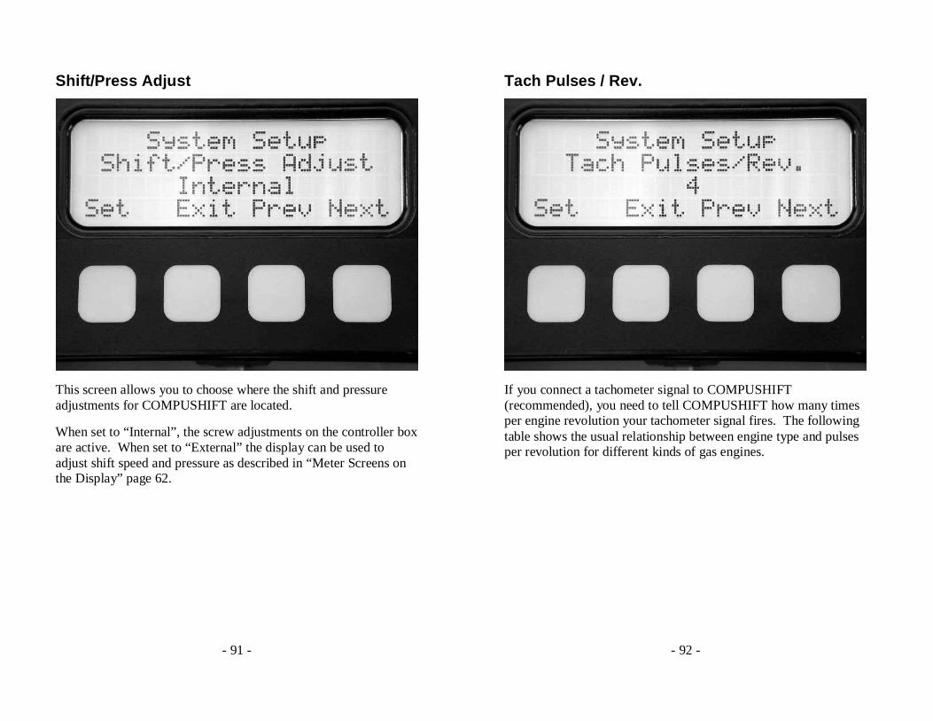
Shift/Press Adjust
This screen allows you to choose where the shift and pressure adjustments for COMPUSHIFT are located.
When set to “Internal”, the screw adjustments on the controller box are active. When set to “External” the display can be used to adjust shift speed and pressure as described in “Meter Screens on the Display” page 62.
- 92 -
Tach Pulses / Rev.
If you connect a tachometer signal to COMPUSHIFT (recommended), you need to tell COMPUSHIFT how many times per engine revolution your tachometer signal fires. The following table shows the usual relationship between engine type and pulses per revolution for different kinds of gas engines.
- 93 -
Engine Type Tach Pulses / Rev.
V8 4
V6 or inline 6 3
Inline 4 2
V12 6
Crank sensor 1
You should check with your ignition, engine, or vehicle vendor to confirm this setting.
- 94 -
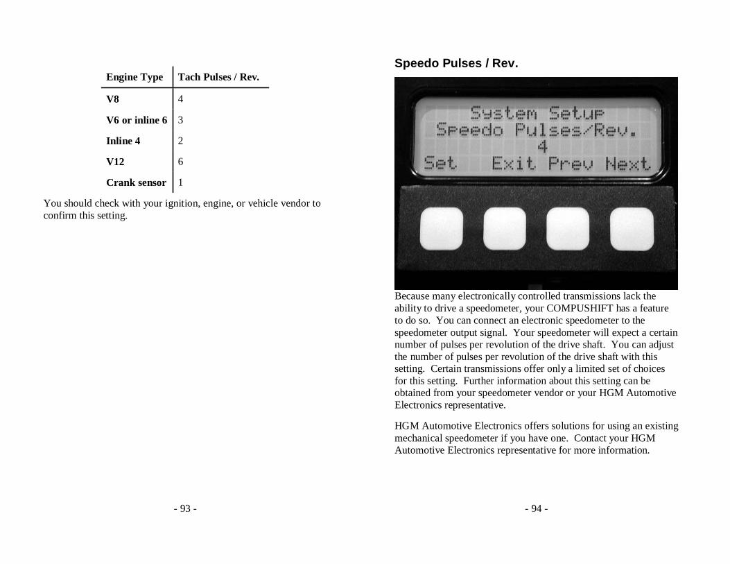
Speedo Pulses / Rev.
Because many electronically controlled transmissions lack the ability to drive a speedometer, your COMPUSHIFT has a feature to do so. You can connect an electronic speedometer to the speedometer output signal. Your speedometer will expect a certain number of pulses per revolution of the drive shaft. You can adjust the number of pulses per revolution of the drive shaft with this setting. Certain transmissions offer only a limited set of choices for this setting. Further information about this setting can be obtained from your speedometer vendor or your HGM Automotive Electronics representative.
HGM Automotive Electronics offers solutions for using an existing mechanical speedometer if you have one. Contact your HGM Automotive Electronics representative for more information.
- 95 -
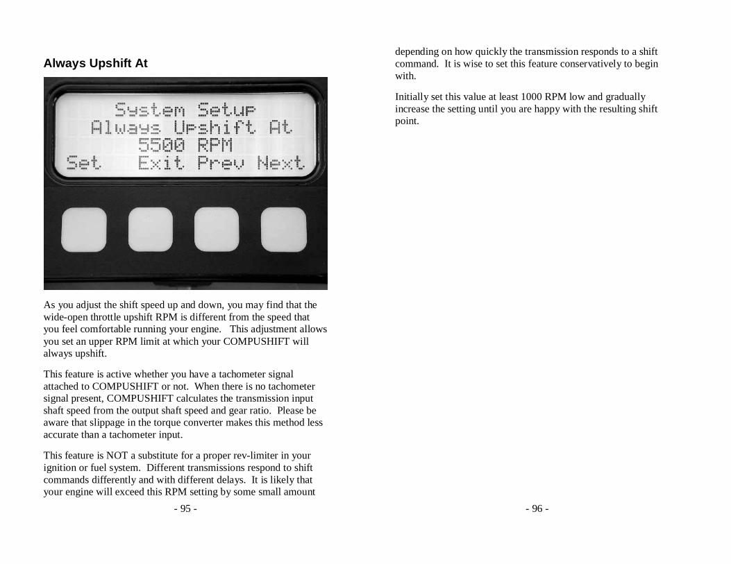
Always Upshift At
As you adjust the shift speed up and down, you may find that the wide-open throttle upshift RPM is different from the speed that you feel comfortable running your engine. This adjustment allows you set an upper RPM limit at which your COMPUSHIFT will always upshift.
This feature is active whether you have a tachometer signal attached to COMPUSHIFT or not. When there is no tachometer signal present, COMPUSHIFT calculates the transmission input shaft speed from the output shaft speed and gear ratio. Please be aware that slippage in the torque converter makes this method less accurate than a tachometer input.
This feature is NOT a substitute for a proper rev-limiter in your ignition or fuel system. Different transmissions respond to shift commands differently and with different delays. It is likely that your engine will exceed this RPM setting by some small amount
- 96 -
depending on how quickly the transmission responds to a shift command. It is wise to set this feature conservatively to begin with.
Initially set this value at least 1000 RPM low and gradually increase the setting until you are happy with the resulting shift point.
- 97 -
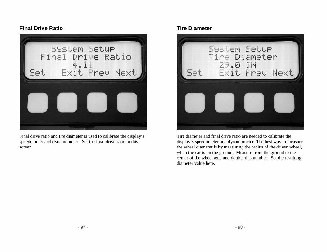
Final Drive Ratio
Final drive ratio and tire diameter is used to calibrate the display’s speedometer and dynamometer. Set the final drive ratio in this screen.
- 98 -
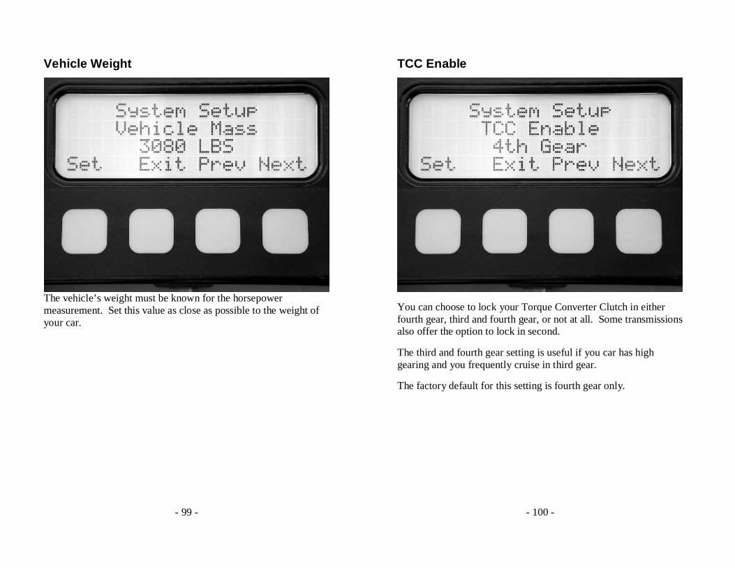
Tire Diameter
Tire diameter and final drive ratio are needed to calibrate the display’s speedometer and dynamometer. The best way to measure the wheel diameter is by measuring the radius of the driven wheel, when the car is on the ground. Measure from the ground to the center of the wheel axle and double this number. Set the resulting diameter value here.
- 99 -
Vehicle Weight
The vehicle’s weight must be known for the horsepower measurement. Set this value as close as possible to the weight of your car.
- 100 -
TCC Enable
You can choose to lock your Torque Converter Clutch in either fourth gear, third and fourth gear, or not at all. Some transmissions also offer the option to lock in second.
The third and fourth gear setting is useful if you car has high gearing and you frequently cruise in third gear.
The factory default for this setting is fourth gear only.

- 101 -
TCC Enable Speed
Sometimes the combination of final drive ratio and tire sizes makes a car perform poorly below certain speeds while using the torque converter clutch. This is especially true if the engine does not produce much low-end torque. This adjustment allows you to set the minimum speed at which the torque converter clutch can lock.
- 102 -
TCC Max Throttle
As you increase throttle, the torque converter clutch should disengage to allow the torque converter to multiply torque for greater acceleration. This parameter allows you to adjust the throttle position where the TCC disengages. For cars with higher torque engines, this parameter can be set higher.
In order to protect the torque converter clutch from being overpowered and damaged, COMPUSHIFT will not allow lock up at more than 50% throttle.
- 103 -
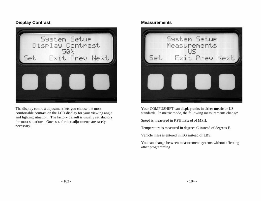
Display Contrast
The display contrast adjustment lets you choose the most comfortable contrast on the LCD display for your viewing angle and lighting situation. The factory default is usually satisfactory for most situations. Once set, further adjustments are rarely necessary.
- 104 -
Measurements
Your COMPUSHIFT can display units in either metric or US standards. In metric mode, the following measurements change:
Speed is measured in KPH instead of MPH.
Temperature is measured in degrees C instead of degrees F.
Vehicle mass is entered in KG instead of LBS.
You can change between measurement systems without affecting other programming.
- 105 -
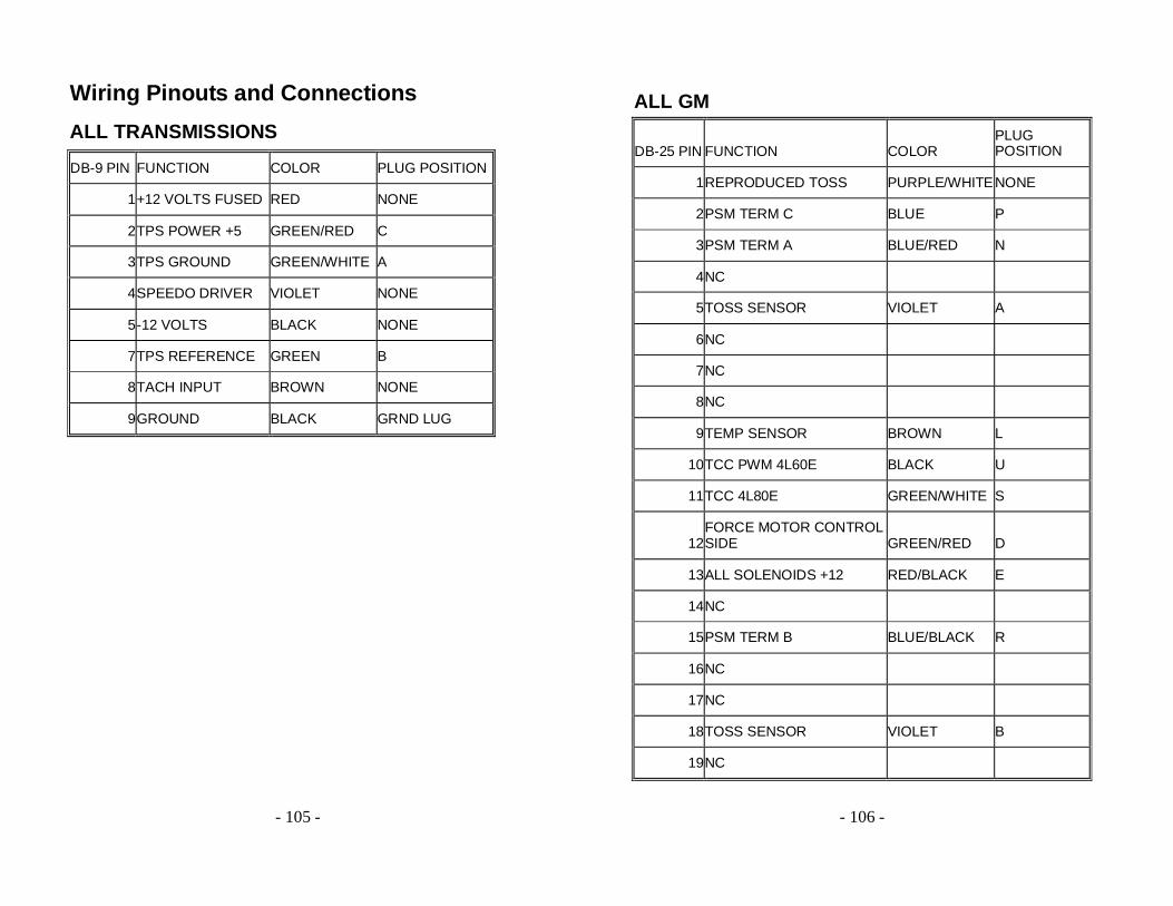
Wiring Pinouts and Connections
ALL TRANSMISSIONS
DB-9 PIN FUNCTION COLOR PLUG POSITION
1+12 VOLTS FUSED RED NONE
2TPS POWER +5 GREEN/RED C
3TPS GROUND GREEN/WHITE A
4SPEEDO DRIVER VIOLET NONE
5-12 VOLTS BLACK NONE
7TPS REFERENCE GREEN B
8TACH INPUT BROWN NONE
9GROUND BLACK GRND LUG
- 106 -
ALL GM
DB-25 PIN FUNCTION COLOR PLUG POSITION
1REPRODUCED TOSS PURPLE/WHITE NONE
2PSM TERM C BLUE P
3PSM TERM A BLUE/RED N
4NC
5TOSS SENSOR VIOLET A
6NC
7NC
8NC
9TEMP SENSOR BROWN L
10TCC PWM 4L60E BLACK U
11TCC 4L80E GREEN/WHITE S
12FORCE MOTOR CONTROL SIDE GREEN/RED D
13ALL SOLENOIDS +12 RED/BLACK E
14NC
15PSM TERM B BLUE/BLACK R
16NC
17NC
18TOSS SENSOR VIOLET B
19NC
- 107 -
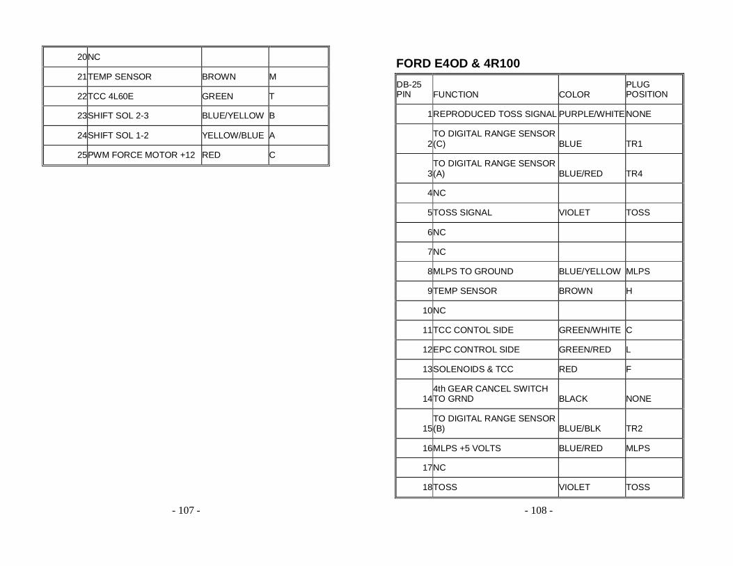
20NC
21TEMP SENSOR BROWN M
22TCC 4L60E GREEN T
23SHIFT SOL 2-3 BLUE/YELLOW B
24SHIFT SOL 1-2 YELLOW/BLUE A
25PWM FORCE MOTOR +12 RED C
- 108 -
FORD E4OD & 4R100
DB-25 PIN FUNCTION COLOR
PLUG POSITION
1 REPRODUCED TOSS SIGNAL PURPLE/WHITE NONE
2 TO DIGITAL RANGE SENSOR (C) BLUE TR1
3 TO DIGITAL RANGE SENSOR (A) BLUE/RED TR4
4 NC
5 TOSS SIGNAL VIOLET TOSS
6 NC
7 NC
8 MLPS TO GROUND BLUE/YELLOW MLPS
9 TEMP SENSOR BROWN H
10 NC
11 TCC CONTOL SIDE GREEN/WHITE C
12 EPC CONTROL SIDE GREEN/RED L
13 SOLENOIDS & TCC RED F
14 4th GEAR CANCEL SWITCH TO GRND BLACK NONE
15 TO DIGITAL RANGE SENSOR (B) BLUE/BLK TR2
16 MLPS +5 VOLTS BLUE/RED MLPS
17 NC
18 TOSS VIOLET TOSS
- 109 -
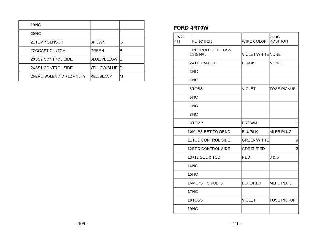
19 NC
20 NC
21 TEMP SENSOR BROWN G
22 COAST CLUTCH GREEN B
23 SS2 CONTROL SIDE BLUE/YELLOW E
24 SS1 CONTROL SIDE YELLOW/BLUE D
25 EPC SOLENOID +12 VOLTS RED/BLACK M
- 110 -
FORD 4R70W
DB-25 PIN FUNCTION WIRE COLOR
PLUG POSITION
1 REPRODUCED TOSS SIGNAL VIOLET/WHITE NONE
2 4TH CANCEL BLACK NONE
3 NC
4 NC
5 TOSS VIOLET TOSS PICKUP
6 NC
7 NC
8 NC
9 TEMP BROWN 1
10 MLPS RET TO GRND BLU/BLK MLPS PLUG
11 TCC CONTROL SIDE GREEN/WHITE 9
12 EPC CONTROL SIDE GREEN/RED 2
13 +12 SOL & TCC RED 8 & 6
14 NC
15 NC
16 MLPS +5 VOLTS BLUE/RED MLPS PLUG
17 NC
18 TOSS VIOLET TOSS PICKUP
19 NC
- 111 -
20 NC
21 TEMP BROWN 3
22 NC
23 SS2 CONTROL SIDE BLUE/YELLOW 4
24 SS1 CONTROL SIDE YELLOW/BLUE 7
25 +12 EPC SOL RED/BLACK 5
- 112 -
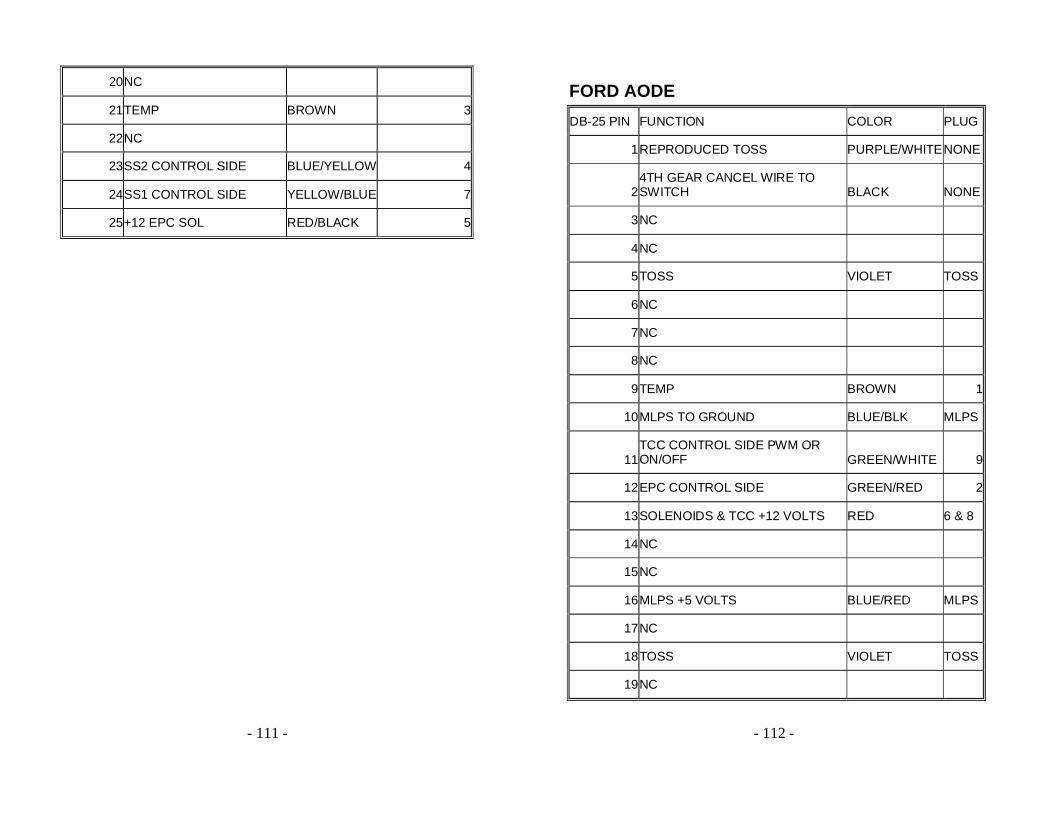
FORD AODE
DB-25 PIN FUNCTION COLOR PLUG
1 REPRODUCED TOSS PURPLE/WHITE NONE
2 4TH GEAR CANCEL WIRE TO SWITCH BLACK NONE
3 NC
4 NC
5 TOSS VIOLET TOSS
6 NC
7 NC
8 NC
9 TEMP BROWN 1
10 MLPS TO GROUND BLUE/BLK MLPS
11 TCC CONTROL SIDE PWM OR ON/OFF GREEN/WHITE 9
12 EPC CONTROL SIDE GREEN/RED 2
13 SOLENOIDS & TCC +12 VOLTS RED 6 & 8
14 NC
15 NC
16 MLPS +5 VOLTS BLUE/RED MLPS
17 NC
18 TOSS VIOLET TOSS
19 NC
- 113 -
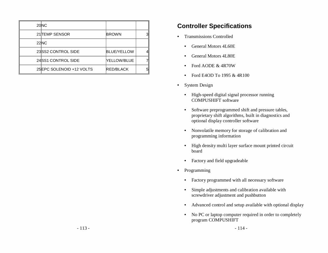
20 NC
21 TEMP SENSOR BROWN 3
22 NC
23 SS2 CONTROL SIDE BLUE/YELLOW 4
24 SS1 CONTROL SIDE YELLOW/BLUE 7
25 EPC SOLENOID +12 VOLTS RED/BLACK 5
- 114 -
Controller Specifications
• Transmissions Controlled
• General Motors 4L60E
• General Motors 4L80E
• Ford AODE & 4R70W
• Ford E4OD To 1995 & 4R100
• System Design
• High-speed digital signal processor running COMPUSHIFT software
• Software preprogrammed shift and pressure tables, proprietary shift algorithms, built in diagnostics and optional display controller software
• Nonvolatile memory for storage of calibration and programming information
• High density multi layer surface mount printed circuit board
• Factory and field upgradeable
• Programming
• Factory programmed with all necessary software
• Simple adjustments and calibration available with screwdriver adjustment and pushbutton
• Advanced control and setup available with optional display
• No PC or laptop computer required in order to completely program COMPUSHIFT

- 115 -
• Shift Sequencing
• Automatic shifting controlled by shift lever, vehicle speed and throttle position
• Manual mode controlled by shift lever only
• Adjustable with screw adjustment or display
• Shift Quality
• Automatic control based on throttle position and heuristic algorithm
• Adjustable with screw adjustment or display
• Torque Converter Clutch
• Lock and unlock based on throttle position, vehicle speed, gear
• User adjustable lock based on vehicle speed
• User adjustable unlock based on throttle position
• User adjustable lock based on transmission gear. Available operating modes are “Never”, “3rd and 4th gear” or “4th gear only”.
• Chassis
• Chassis is a factory sealed black powder coated aluminum box with mounting flanges. There are no user serviceable parts inside. The chassis should not be opened.
• Dimensions
• 3.75 x 4.5 x 2.25” excluding mounting flanges
• Mounting flange dimensions
- 116 -
• 3.75 x .5” (two flanges, opposite ends)
• Mounting slots
• 2 slots per flange, beveled to take a #8 oval head sheet metal screw
• Mounting Requirements
• Controller must be mounted in a dry area, not exposed to heating by exhaust, cooling, or heating system
• Controller must have a clear air circulation. A 1” air clearance around sides and top is recommended.
• Environmental Requirements
• Relative Humidity
• 0-90%, non-condensing
• Temperature (Operating)
• -30 to 60 C (-22 to 140 F)
• Temperature (Storage)
• -30 to 85 C (-22 to 185 F)
• Protection
• Automatic internal shutdown for over temperature condition
• Automatic protection against failed solenoids
• Electrical Specifications
• Supply Voltage
• 8 to 16 Volts DC
- 117 -
• Supply Current, Quiescent
• 600ma @ 14.4 Volts
• Supply Current, Maximum
• 5 A @14.4 Volts (dependent on transmission type)
• Solenoid Capacity
• 6 Solenoids with automatic short circuit protection
• Short and open circuit detection with fault reporting
• Tachometer Input
• High impedance 0 to 12 Volt signal input.
• Tachometer input not required. Used for wide-open throttle upshift and optional display and data log
• Speedometer Input
• Designed for variable reluctance inductive pickup on GM and Ford transmissions
• Can function with appropriately conditioned 0 to 12 Volt signal
• Speedometer Outputs
• Reproduced OEM TOSS Signal
• Variable pulse count per drive shaft revolution
• Throttle Position Sensor Input
• 0 to 5V input, filtered against line noise
• Automatic calibration to stroke range
- 118 -
• 5 V reference signal provided
• Connectors
• Female DB 25 for transmission connection
• Male DB 9 for power supply, tachometer input, speedometer output, throttle position sensor
• RJ-11 for connection to optional display
• Indicators
• 1 Red LED indicating system status and fault codes
• Adjustments
• 1 Shift Speed adjustment potentiometer, screwdriver adjustable
• 1 Shift Pressure adjustment potentiometer, screwdriver adjustable
• 1 Throttle Position Sensor calibration switch
- 119 -
Display Specifications
• Type
• Handheld or dash mountable backlit LCD display with 4 key keypad
• Display Characteristics
• Number of characters
• 80 (20 Characters x 4 Lines)
• Matrix format
• 5 x 7 with underline
• Display area
• 76.3 x 25.2mm (XxY)
• Character size
• 2.95 x 4.75mm (XxY), not including underline
• LED Backlight
• 100,000 hours typical life
• Yellow green color
• Chassis
• Chassis is a factory sealed black powder coated box with a pair of threaded inserts for mounting. There are no user serviceable parts inside. The chassis should not be opened.
• Dimensions
• 4.25 x 3.125 x 1.75”
- 120 -
• Threaded Inserts
• 10-32 machine screw
• Environmental Requirements
• Relative Humidity
• 0-90%, non-condensing
• Temperature (Operating)
• 0 to +50 C (+32 to +122 F)
• Temperature (Storage)
• -20 to +70 C (-4 to 158 F)
• Mounting Requirements
• Display must be mounted in a dry area. Direct sunlight should be avoided.
• Shock and Vibration
• Normal automotive environment. The display should not be dropped.
• Electrical Specifications
• All electrical power is provided by the COMPUSHIFT controller
• Connection is via a provided standard 4-pin telephone cord
• Display Formats
• Mixed display of information in small characters
• Large digits
- 121 -
• Bar graphs
• Running Dashboard Displays
• The display provides a number of meters while the system is operating. These include:
• System Status and Diagnostics
• Vehicle Speed
• Engine Speed
• Current Gear
• Throttle Position
• Relative Hydraulic Pressure
• Transmission Temperature
• System Voltage
• Dynamometer
• Accelerometer
• Stopwatch with Lap Times
• Data Log
• Remote Adjustments
• Shift Pressure
• Shift Speed
• Advanced Setup Features
• The display allows use of an extended set of programming features including:
- 122 -
• Transmission Type Selection
• Transmission Shift Mode Selection
• Torque Converter Clutch Parameters
• Tachometer Calibration
• Speedometer Calibration
• Tire Size
• Final Drive Ratio
• Vehicle Weight
• Measurement Units
- 123 -
AccuLink Throttle Position Sensor Specifications
• Description
• Carburetor mounted, direct linkage actuated sealed variable resistor sensor with spring preload.
• Linkage
• Adjustable stainless steel linkage arm, ratio arm, sensor arm
• Mounting Hardware
• Stainless steel nuts, washers, brackets and screws
• Environmental Requirements
• Relative Humidity
• 0-90%
• Temperature (Operating and Storage)
• -30 to 85 C (-22 to 185 F)
• Adjustments
• Rotational adjustment on sensor
• Alignment adjustment on sensor bracket
• Linkage length adjustment on arm
• Mounting angle adjustment on ratio arm
• Attachment
• Direct attachments to throttle linkage and intake manifold
- 124 -
Cable Throttle Position Sensor Specifications
• Type
• Cable actuated sealed variable resistor with spring preload
• Chassis
• Chassis is a black powder coated aluminum box with mounting flanges. The throttle cable exits one side of the box.
• Dimensions
• 4.25 x 3.125 x 1.75” excluding mounting flanges
• Mounting flange dimensions
• 3.125 x .5” (two flanges, opposite ends)
• Mounting slots
• 2 slots per flange, beveled to take a #8 oval head sheet metal screw
• Environmental Requirements
• Relative Humidity
• 0-90%
• Temperature (Operating and Storage)
• -30 to 85 C (-22 to 185 F)
• Cable
• Type
- 125 -
• Steel cable in prelubricated high temperature plastic housing
• Mounting
• Cable housing attaches to a flange with a pair of provide nuts on the threaded housing end.
• Dimensions
• 3’ L x 3/8”D
• Travel
• 3/4”
• Adjustment
• Screw adjustment on cable length
• Attachment
• Socket type attachment to provided stud
- 126 -
Warranty
For a period of one year after purchase, HGM Automotive Electronics will repair or replace, at its expense and its option, any COMPUSHIFT component that in normal use has proven to be defective in workmanship or material. The customer must return the component prepaid to HGM Automotive Electronics with proof of purchase to allow opportunity to verify the alleged defect by inspection.
HGM Automotive Electronics will not be responsible for any asserted defect which specifically resulted from normal wear, misuse, abuse or repair or alteration made by anyone other than an authorized HGM Automotive Electronics representative or service facility.
Under no circumstances will HGM Automotive Electronics be liable for incidental or consequential damages resulting from defective products.
This warranty is the sole warranty and sets forth the customer’s exclusive remedy. All other warranties, express or implied, including fitness for purpose are expressly disclaimed by HGM Automotive Electronics.