omni-vii programmers reference guide - ten-tec · 2018-10-11 · rev 1.009 omni-vii programmer’s...
TRANSCRIPT

Rev 1.009 OMNI-VII Programmer’s Reference Guide 1 of 63OMNI-VII Firmware Updates at www.rfsquared.com
OMNI-VIIModel 588
ProgrammersReference
GuideRevision 1.009

Rev 1.009 OMNI-VII Programmer’s Reference Guide 2 of 63OMNI-VII Firmware Updates at www.rfsquared.com
Introduction.................................................................................................................. 4Conventions Used in This Manual ........................................................................... 6Interface Settings ...................................................................................................... 7
Serial Connection .................................................................................................. 7Ethernet Connection .............................................................................................. 8
The OMNI-VII Command Set ..................................................................................... 9OMNI-VII Command Set Quick List ..................................................................... 10RADIO MODE Command Set ............................................................................... 15
Frequency Tuning................................................................................................ 15AGC Mode Control ............................................................................................. 16Squelch (all mode)............................................................................................... 16RF Gain ............................................................................................................... 17RF Attenuation Control ....................................................................................... 17Noise Blanker, Noise Reduction, and Automatic Notch..................................... 18Receive and Transmit Modes .............................................................................. 18Passband Tuning (PBT)....................................................................................... 19AF (Audio Volume) ............................................................................................ 19Version – Query Only ......................................................................................... 20Receive Filter ...................................................................................................... 20Where – AT......................................................................................................... 21Execution Control ............................................................................................... 21SUNIT – Query Only .......................................................................................... 22Transmit............................................................................................................... 23Split State – Radio Mode..................................................................................... 24Main Mode Query – Orion Format ..................................................................... 24
REMOTE MODE Command Set ........................................................................... 25Ethernet Settings – Query Only........................................................................... 26Frequency Tuning................................................................................................ 27Receive / Transmit Offset.................................................................................... 28Audio Source....................................................................................................... 29Keying Loop On/Off ........................................................................................... 30CW RISE/FALL TIME....................................................................................... 30Mic Gain.............................................................................................................. 31Line Gain............................................................................................................. 31Speech Processor................................................................................................. 32FM CTCSS Tones ............................................................................................... 32RX Equalizer ....................................................................................................... 33TX Equalizer ....................................................................................................... 33Transmit Roll Off ................................................................................................ 34External T/R Delay.............................................................................................. 34Sidetone Frequency ............................................................................................. 35CW QSK Delay................................................................................................... 35Transmit Enable .................................................................................................. 36Sideband Transmit Bandwidth ............................................................................ 37Auto Tuner .......................................................................................................... 38

Rev 1.009 OMNI-VII Programmer’s Reference Guide 3 of 63OMNI-VII Firmware Updates at www.rfsquared.com
Sidetone Volume ................................................................................................. 38SPOT Volume ..................................................................................................... 39FSK Mark High/Low........................................................................................... 39I-F Filter Selection............................................................................................... 40I-F Filter Enable .................................................................................................. 40Antenna ............................................................................................................... 41Monitor................................................................................................................ 41Transmit Power ................................................................................................... 42SPOT Tone On/Off ............................................................................................. 42PREAmp On/Off ................................................................................................. 43Remote Tune ....................................................................................................... 43Split State – Extended Format............................................................................. 44VOX TRIP Level................................................................................................. 44ANTI VOX Level................................................................................................ 45VOX Hang Time ................................................................................................. 45CW Keyer Mode ................................................................................................. 46CW Keyer Weighting.......................................................................................... 46Manual NOTCH On/Off ..................................................................................... 47Manual NOTCH Center Frequency .................................................................... 47Manual NOTCH Width ....................................................................................... 48Internal Keyer Speed ........................................................................................... 48VOX On/Off........................................................................................................ 49RADIO DISPLAY ON/OFF ............................................................................... 49RADIO SPEAKER ON/OFF .............................................................................. 50TRIP Gain............................................................................................................ 50
Operation with Optional 302 Remote Encoder.......................................................... 51POD PASSTHRU Command ................................................................................. 51POD PASSTHRU Notification............................................................................... 52POD ENCODER Notification ................................................................................ 53
Serial Device Control via Ethernet ............................................................................ 54Serial Pass Thru ...................................................................................................... 54Serial Echo Mode ................................................................................................... 55
CWType ..................................................................................................................... 57Ethernet Audio ........................................................................................................... 59
RIP (Radio over IP) Introduction ........................................................................... 59TRIP (Transmit over IP) Introduction .................................................................... 59RIP Audio Packet Format ....................................................................................... 60TRIP Audio Packet Format .................................................................................... 61
Ethernet Command/Query Format............................................................................. 61Document Revision History....................................................................................... 62

Rev 1.009 OMNI-VII Programmer’s Reference Guide 4 of 63OMNI-VII Firmware Updates at www.rfsquared.com
Ten-Tec has produced this document as a starting point for software developersundertaking the development of a PC based OMNI-VII (Model 588) Interface program.The Ten-Tec OMNI-VII DSP HF transceiver is a product that is defined more byfirmware than hardware. As such, it is subject to change based on customer needs. It isadvisable to check for a more recent update at the Ten-Tec firmware update site,www.rfsquared.com. This specification is intended for OMNI-VII Version 1.005 or later.
There are two levels of command interface protocols provided. The two levels ofcommands are designed for two different operating modes of the OMNI-VII.
The first Operating Mode is referred to as “RADIO MODE”. In “RADIO MODE”only the base level of commands is available, and they are available only on the SerialInterface. This is the command-set that is already utilized by the Jupiter in Jupiter mode.A few of these commands have a parameter list that is extended to encompass addeditems for that command. This makes the base level of the OMNI-VII in Radio Modecompatible with control programs that already exist. The purpose of “RADIO MODE” isfor the radio user who wants to control the rig traditionally from the front panel.Changing frequencies, watching the Power Meter, switching bands, and adjusting themyriad of other controls, just like it is done with an Orion or Jupiter.
The second Operating Mode is referred to as “REMOTE MODE”. In order to getfully functional control of all of the OMNI-VII’s operating parameters, then it isnecessary to operate the OMNI-VII in “REMOTE MODE”. In this mode, the fullcommand set is available on the Ethernet interface, and also the serial port. The purposefor “REMOTE MODE” is to be able to control the radio 100% through the Serial and/orEthernet interfaces. “REMOTE MODE” also provides for the audio streaming featuresof RIP and TRIP.
RIP is an acronym for Radio over IP. This is the receive audio that is heard via theOMNI-VII’s speaker. In the case of the REMOTE Mode radio, this audio is then RIP’dfrom the OMNI-VII via the Ethernet to a computer for playback on the computer’sspeaker.
TRIP is an acronym for TRansmit audio over IP. Normally, transmit audio comesfrom a microphone on the radio and is transmitted over the air by the radio. In theinstance of the Ethernet, it is the audio recorded on a microphone on a computer, and thentransmitted on the Ethernet in a packet for the OMNI-VII to subsequently transmit overthe air.
Introduction

Rev 1.009 OMNI-VII Programmer’s Reference Guide 5 of 63OMNI-VII Firmware Updates at www.rfsquared.com
Since the OMNI-VII provides future growth for up to a total of 6 completelyindependent modes. It is possible that even further additions will be made to support theadded capabilities of the other modes.
Holdings down a digit on the band stack keyboard of the front panel accesses eachmode. For “RADIO MODE”, press and hold the “1” digit until you see the Versionstring including the word RADIO. For “REMOTE MODE”, press and hold the “2” digituntil you see the Version string including the word REMOTE. If you accidentally pressthe wrong number (e.g. 3 through 6), then the OMNI-VII will tell you that this specificoperating mode is not present. If this occurs, then you should turn off the OMNI-VII, andtry again. If you accidentally press any other key, then you won’t see the radio versionstring displayed, instead you will have forced the radio to remain in “BOOT LOADERMODE”. Again, turn off the radio, and try again making sure you hold down the properkey to get to the proper mode.
To add more value to a remote based radio, the OMNI-VII has the capability ofaccepting Ethernet commands that are intended to be delivered to a serial device, such asa SteppIR Antenna Controller. This is referred to as “Serial Passthru”. The OMNI-VIIalso has the capability of being put into a mode where any data it receives in on the serialport, it can echo back to the Ethernet port. This is referred to as “Serial Echo”. Thismakes it possible for a remotely placed OMNI-VII to be capable of being a portal tocontrolling and getting status from other serial devices at the ham shack.
Another functionality that the OMNI-VII has is the ability to provide a way to sendto the Serial Interface pod key presses. This functionality is invoked when the OMNI-VIIreceives a command to tell it to start “POD PASSTHRU”. From that moment on,anytime a pod key is pressed, the OMNI-VII will not process the key, but will send anotification out the serial port that a given POD key has been depressed. When released,notification is sent again out the serial port that the given POD key has been released.This allows control programs to extend the functionality of the radio with programswritten on the PC. This functionality already exists in other TenTec Transceivers, namelythe Orion, Orion2, and Jupiter and it is already in use by various control program codesavailable on the market today.
The command set described in this manual does not include the command set utilizedby the OMNI-VII Boot/Loader program for programming the OMNI-VII. The commandset described in this manual only covers the command set that is utilized for radiocommand and control functions.

Rev 1.009 OMNI-VII Programmer’s Reference Guide 6 of 63OMNI-VII Firmware Updates at www.rfsquared.com
Information contained in this document applies to firmware version 0.114 and later.Numeric Types:
0x0A Hexadecimal Numbers.<dn> 8 bit numbers10 Decimal Number.‘A’ ASCII character code.
Example: ASCII ‘A’ is 0x41.<CR> a byte containing the value of <0x0d> for a carriage return
Conventions Used in This Manual

Rev 1.009 OMNI-VII Programmer’s Reference Guide 7 of 63OMNI-VII Firmware Updates at www.rfsquared.com
Serial ConnectionThe RS-232 serial interface on the OMNI-VII is handled via a 16C550 UART
located on the DSP/Logic board. The interface parameters are fixed at 57,600 baud, NoParity, 8 Data bits, 1 Stop bit. The UART uses hardware handshaking to control the dataflow between the PC and the radio. The host PC should be set to use RTS/CTS signaling.
This is the same regardless of whether the topic is command and control interface onthe serial port or using the serial port for serial pass thru or serial echo modes.
The diagram below shows the wiring and associated signals for a 9 pin to 9 pin serialcable required to connect the OMNI-VII transceiver to a standard PC. If you purchase apre-made serial cable it should be a straight through cable.
Computer Pin OMNI-VIICD. 1 N.C.RXD 2 Serial Data OutTXD 3 Serial Data InDTR 4 N.C.GND 5 GNDDSR 6 N.C.RTS (out) 7 RTS (in)CTS (in) 8 CTS (out)RI 9 N.C.
COMPUTER OMNI-VII
The serial port of the OMNI-VII is defined as a DCE terminal. Which means that itis meant to be connected to a Computers DTE terminal. Using a straight through RS-232control line. If you wish to control another serial device, and if it is a DCE terminal typeof a device also, then the cable you need to use is a null-modem RS232 Interface cable. If
Interface Settings

Rev 1.009 OMNI-VII Programmer’s Reference Guide 8 of 63OMNI-VII Firmware Updates at www.rfsquared.com
the other device is a DTE, then you will need to use a standard straight RS232 interfacecable.
In order to use the OMNI-VII in remote mode, but you intend on controlling the rigonly by the serial port, then it is suggested that you disable the Ethernet activities of theOMNI-VII. Setting the first octet of the G8WAY IPADDR to 0 disables Ethernetactivities.
Ethernet ConnectionThe Ethernet interface on the OMNI-VII is handled via a Realtek RTL8019AS Full
Duplex Ethernet Controller located on the DSP/Logic board. This Network InterfaceController (NIC) is fully compliant with Ethernet II and IEEE802.3 10Base5, 10Base2,and 10BaseT. The full-duplex function of the NIC enables simultaneously transmissionand reception on the twisted-pair link to a Full Duplex Ethernet switching hub. Thisfeature not only increases the channel bandwidth from 10 to 20 Mbps but also avoids theperformance degradation problem due to the channel contention characteristics of theEthernet CSMA/CD protocol. This connection is configured for 10Mbps, so it iscompatible with all 10/100 networks.
Depending upon how you want to connect your OMNI-VII to another computer viathe Ethernet Interface, there are two types of cables that you can choose. If youremember, for serial communications, you either pick a standard serial cable or a null-modem serial cable. The same is true in principle for Ethernet connections. If you aregoing to connect the OMNI-VII directly to a computer, then you will need to use a“cross-over” Ethernet patch cable. If you are going to connect the OMNI-VII to a hub orrouter or gateway, then you will need to use a “standard” Ethernet patch cable.
In either case, you can use either a CAT-5E (350Mhz) high-speed patch cord, or youcan use a CAT-6 Networking Cable. Either will satisfy the bandwidth requirements of theOMNI-VII. They both follow EIA/TIA 568B Wiring, and are equipped with RJ-45connectors.

Rev 1.009 OMNI-VII Programmer’s Reference Guide 9 of 63OMNI-VII Firmware Updates at www.rfsquared.com
The command set is extensive and every effort has been made to keep the individualcommands as simple as possible. Although the OMNI-VII Serial interface operates at57,600 baud and the Ethernet interface operates at 10Mbps short commands are used tokeep the processing overhead to a minimum.
In general an OMNI-VII instruction is a series of ASCII characters which may befollowed by data and then terminated by a carriage return <CR>. Command charactersare case sensitive! In general, the query are identical to the set command except thecommand is prefixed with a ‘?’ character.
The OMNI-VII interface requires that data be in a format compatible with eachcommand. Programmers should ensure that the supplied data is correct. For the Serialinterface, where a command is unrecognized or data is invalid the radio will send back aresponse consisting of the letter ‘Z’ followed by the first character of the command stringthat caused the error and finally, a carriage return <CR>. For the Ethernet Interface,there is no invalid command reply. So it is a best practice if a command is sent, then theassociated query should also be used to verify the new setting.
Because the OMNI-VII is designed so that it could be reprogrammed in-system thecommand set presented here is subject to change or enhancement. We will make everyeffort to make the system backward compatible with existing documented commandswhenever possible. However, the OMNI-VII is a HF TRASNCEIVER PLATFORM thatcould host a variety of radio services. Persons or companies developing control softwarefor the OMNI-VII should not assume that the radio is operating original factory firmwarebut rather should always query the radio firmware revision to ensure compatibility.
There is one specialized query “?*” which is used to query all of the settings,returned in one response, relevant to the operating mode of the radio. In the Radio Mode,it will return all of the possible Radio Mode responses, and in Remote Mote, it will returnall possible Remote Mode responses. If performed over the serial port, then this will be aseries of properly formatted packets pertinent to each response. If performed over theEthernet then this will be one single Ethernet Packet whose data contains all of thepossible formatted packets pertinent to each response.
The OMNI-VII Command Set
Rev 1.009 OMNI-VII Programmer’s Reference Guide 10 of 63OMNI-VII Firmware Updates at www.rfsquared.com
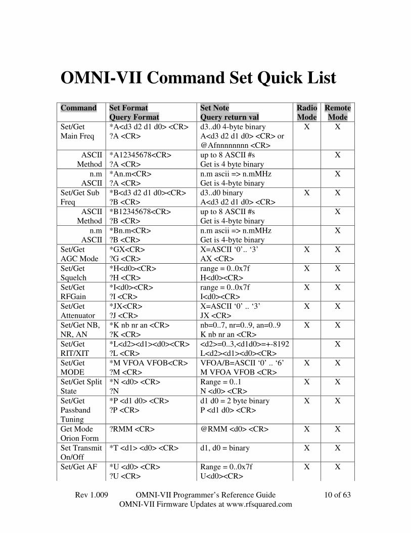
Command Set FormatQuery Format
Set NoteQuery return val
RadioMode
RemoteMode
Set/GetMain Freq
*A<d3 d2 d1 d0> <CR>?A <CR>
d3..d0 4-byte binaryA<d3 d2 d1 d0> <CR> or@Afnnnnnnnn <CR>
X X
ASCIIMethod
*A12345678<CR>?A <CR>
up to 8 ASCII #sGet is 4 byte binary
X
n.mASCII
*An.m<CR>?A <CR>
n.m ascii => n.mMHzGet is 4-byte binary
X
Set/Get SubFreq
*B<d3 d2 d1 d0><CR>?B <CR>
d3..d0 binaryA<d3 d2 d1 d0> <CR>
X X
ASCIIMethod
*B12345678<CR>?B <CR>
up to 8 ASCII #sGet is 4-byte binary
X
n.mASCII
*Bn.m<CR>?B <CR>
n.m ascii => n.mMHzGet is 4-byte binary
X
Set/GetAGC Mode
*GX<CR>?G <CR>
X=ASCII ‘0’.. ‘3’AX <CR>
X X
Set/GetSquelch
*H<d0><CR>?H <CR>
range = 0..0x7fH<d0><CR>
X X
Set/GetRFGain
*I<d0><CR>?I <CR>
range = 0..0x7fI<d0><CR>
X X
Set/GetAttenuator
*JX<CR>?J <CR>
X=ASCII ‘0’ .. ‘3’JX <CR>
X X
Set/Get NB,NR, AN
*K nb nr an <CR>?K <CR>
nb=0..7, nr=0..9, an=0..9K nb nr an <CR>
X X
Set/GetRIT/XIT
*L<d2><d1><d0><CR>?L <CR>
<d2>=0..3,<d1d0>=+-8192L<d2><d1><d0><CR>
X
Set/GetMODE
*M VFOA VFOB<CR>?M <CR>
VFOA/B=ASCII ‘0’ .. ‘6’M VFOA VFOB <CR>
X X
Set/Get SplitState
*N <d0> <CR>?N
Range = 0..1N <d0> <CR>
X X
Set/GetPassbandTuning
*P <d1 d0> <CR>?P <CR>
d1 d0 = 2 byte binaryP <d1 d0> <CR>
X X
Get ModeOrion Form
?RMM <CR> @RMM <d0> <CR> X X
Set TransmitOn/Off
*T <d1> <d0> <CR> d1, d0 = binary X X
Set/Get AF *U <d0> <CR>?U <CR>
Range = 0..0x7fU<d0><CR>
X X
OMNI-VII Command Set Quick List

Rev 1.009 OMNI-VII Programmer’s Reference Guide 11 of 63OMNI-VII Firmware Updates at www.rfsquared.com
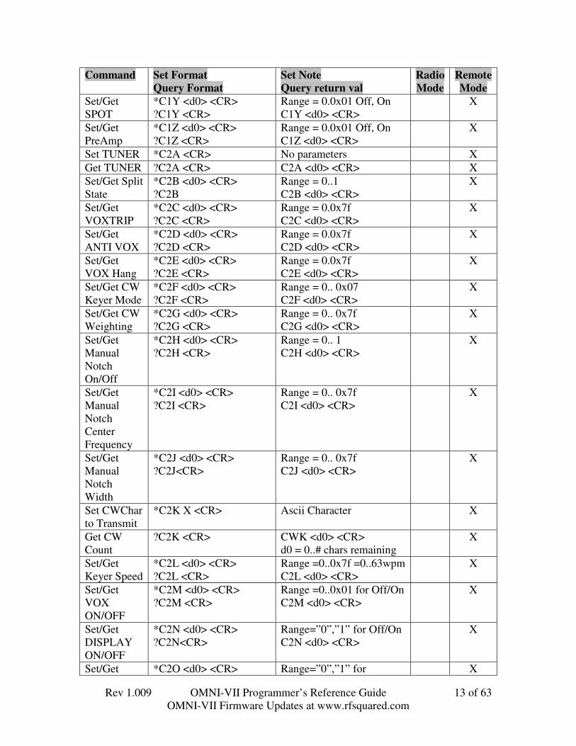
Command Set FormatQuery Format
Set NoteQuery return val
RadioMode
RemoteMode
Set/Get DSPRX Filter
*W <d0> <CR>?W <CR>
Range = 0..0x24W<d0><CR>
X X
Where At (Query only, without ?)XX <CR>
<0x0d><0x0d>“ RADIO START –xxxxxx” RADIO ORREMOTE <0x0d>
X X
Get SUnit ?S <CR>Also Supports “?F<CR>”On the first data bytereturned,If the most significant bit= 1 means returningtransmit power.If the most significant bit=0 means returningsunits.
[F or S] XXYY <CR> ASCII XX Sunits and YY dB aboveOR[F or S] <d1> <d2> <CR> d1<b7>=1 d1<b6..0>=forwardpowerd0=reflected power
X X
Set AudioSource
*C1A <d0> <CR>?C1A <CR>
Range = 0..2C1A <d0> <CR>
X
Set KeyloopOn/Off
*C1B <d0> <CR>?C1B <CR>
Range = 0..1C1B <d0> <CR>
X
Get EthernetSettings
Query ONLY?T <CR>
MAC Address, RIP InProgress, RIP IP,Compression LevelSupported
X
Set/Get CWRise/FallTime
*C1C <d0> <CR>?C1C <CR>
Range = 0..7C1C <d0> <CR>
X
Set/Get MicGain
*C1D <d0> <CR>?C1D <CR>
Range = 0..0x7fC1D <d0> <CR>
X
Set/Get LineGain
*C1E <d0> <CR>?C1E <CR>
Range = 0..0x7fC1E <d0> <CR>
X
Set/GetSpeechProcessor
*C1F <d0> <CR>?C1F <CR>
Range = 0..0x7fC1F <d0> <CR>
X
Set FMCTCSSTone
*C1G <d0> <CR>?C1G <CR>
Range = 0 .. 0x31C1G <d0> <CR>
X
Set/Get RXEqualizer
*C1H <d0> <CR>?C1H <CR>
Range = 0..0x7f –20dB..20dBC1H <d0> <CR>
X
Set/Get TXEqualizer
*C1I <d0> <CR>?C1I <CR>
Range = 0..0x7f –20dB..20dBC1I <d0> <CR>
X
Set/Get *C1J <d0> <CR> Range = 0.0x17- X

Rev 1.009 OMNI-VII Programmer’s Reference Guide 12 of 63OMNI-VII Firmware Updates at www.rfsquared.com
Command Set FormatQuery Format
Set NoteQuery return val
RadioMode
RemoteMode
TransmitRoll Off
?C1J <CR> 70Hz.300HzC1J <d0> <CR>
Set/GetExternalT/R Delay
*C1K <d0> <CR>?C1K <CR>
Range = 0.0x7f – 15ms..1sC1K <d0> <CR>
X
Set/GetSidetoneFrequency
*C1L <d0> <CR>?C1L <CR>
Range = 0.0x7f –0..1270HzC1L <d0> <CR>
X
Set/Get CWQSK Delay
*C1M <d0> <CR>?C1M <CR>
Range = 0.0x7f – 0..1sC1M <d0> <CR>
X
Set/GetTransmitterEnable
*C1N <d0> <CR>?C1N <CR>
Range = 0..1(disable/enable)C1N <d0> <CR>
X
Set/GetSidebandTX BW
*C1O <d0> <CR>?C1O
Range = 0.0x10 –4000..1000HzC1O <d0> <CR>
X
Set/GetAuto Tuner
*C1P <d0> <CR>?C1P <CR>
Range = 0..1 (Not Installed/ Installed)C1P <d0> <CR>
X
Set/GetSidetoneVolume
*C1Q <d0> <CR>?C1Q <CR>
Range = 0.0x7f – 0..1sC1Q <d0> <CR>
X
Set/GetSPOTVolume
*C1R <d0> <CR>?C1R <CR>
Range = 0.0x7f – 0..1sC1R <d0> <CR>
X
Set/Get FSKMarkHigh/Low
*C1S <d0> <CR>?C1S <CR>
Range = 0.1 = Low .. HighC1S <d0> <CR>
X
Set/Get I-FFilterSelection
*C1T <d0> <CR>?C1T <CR>
Range = 0..0x05C1T <d1> <d0> <CR>
X
Set/Get I-FFilterEnable
*C1U <d0> <CR>?C1U <CR>
Range = 0..0x03C1U <d0> <CR>
X
Set/GetAntennaSelection
*C1V <d0> <CR>?C1V <CR>
Range = 0..0x03C1V <d0> <CR>
X
Set/GetMonitor
*C1W <d0> <CR>?C1W <CR>
Range = 0.0x7f – 0..100%C1W <d0> <CR>
X
Set/GetPower
*C1X <d0> <CR>?C1X <CR>
Range = 0.0x7f –0..100WattsC1X <power selected><forward power><reflected power> <CR>
X
Rev 1.009 OMNI-VII Programmer’s Reference Guide 13 of 63OMNI-VII Firmware Updates at www.rfsquared.com
Command Set FormatQuery Format
Set NoteQuery return val
RadioMode
RemoteMode
Set/GetSPOT
*C1Y <d0> <CR>?C1Y <CR>
Range = 0.0x01 Off, OnC1Y <d0> <CR>
X
Set/GetPreAmp
*C1Z <d0> <CR>?C1Z <CR>
Range = 0.0x01 Off, OnC1Z <d0> <CR>
X
Set TUNER *C2A <CR> No parameters XGet TUNER ?C2A <CR> C2A <d0> <CR> XSet/Get SplitState
*C2B <d0> <CR>?C2B
Range = 0..1C2B <d0> <CR>
X
Set/GetVOXTRIP
*C2C <d0> <CR>?C2C <CR>
Range = 0.0x7fC2C <d0> <CR>
X
Set/GetANTI VOX
*C2D <d0> <CR>?C2D <CR>
Range = 0.0x7fC2D <d0> <CR>
X
Set/GetVOX Hang
*C2E <d0> <CR>?C2E <CR>
Range = 0.0x7fC2E <d0> <CR>
X
Set/Get CWKeyer Mode
*C2F <d0> <CR>?C2F <CR>
Range = 0.. 0x07C2F <d0> <CR>
X
Set/Get CWWeighting
*C2G <d0> <CR>?C2G <CR>
Range = 0.. 0x7fC2G <d0> <CR>
X
Set/GetManualNotchOn/Off
*C2H <d0> <CR>?C2H <CR>
Range = 0.. 1C2H <d0> <CR>
X
Set/GetManualNotchCenterFrequency
*C2I <d0> <CR>?C2I <CR>
Range = 0.. 0x7fC2I <d0> <CR>
X
Set/GetManualNotchWidth
*C2J <d0> <CR>?C2J<CR>
Range = 0.. 0x7fC2J <d0> <CR>
X
Set CWCharto Transmit
*C2K X <CR> Ascii Character X
Get CWCount
?C2K <CR> CWK <d0> <CR>d0 = 0..# chars remaining
X
Set/GetKeyer Speed
*C2L <d0> <CR>?C2L <CR>
Range =0..0x7f =0..63wpmC2L <d0> <CR>
X
Set/GetVOXON/OFF
*C2M <d0> <CR>?C2M <CR>
Range =0..0x01 for Off/OnC2M <d0> <CR>
X
Set/GetDISPLAYON/OFF
*C2N <d0> <CR>?C2N<CR>
Range=”0”,”1” for Off/OnC2N <d0> <CR>
X
Set/Get *C2O <d0> <CR> Range=”0”,”1” for X

Rev 1.009 OMNI-VII Programmer’s Reference Guide 14 of 63OMNI-VII Firmware Updates at www.rfsquared.com
Command Set FormatQuery Format
Set NoteQuery return val
RadioMode
RemoteMode
SpeakerMUTE
?C2O<CR> UnMute / MuteC2O <d0> <CR>
TRIP Gain *C2P <d0> <CR>?C2P<CR>
Range=”1”,”9” for shiftlvlC2P <d0> <CR>
X
Rev 1.009 OMNI-VII Programmer’s Reference Guide 15 of 63OMNI-VII Firmware Updates at www.rfsquared.com
In this section, we will explore the command set available on the Serial Interfacewhen the radio is in RADIO MODE. Unless otherwise specified, queries use the samecommand letter, except that instead of an Asterisk, use a “?”. E.g. *A sets mainfrequency, ?A requests Main Frequency. Value returned is in same format as thecommand format for that value.
Frequency TuningTuning the OMNI-VII is accomplished by two commands that provide the frequency
entry into either the main or sub frequency. The frequency data is the desired frequencyin Hz formatted as a 4-byte binary number.
Once this command is sent, follow it with a Frequency Query, because the OMNI-VII will limit the frequencies to supported ranges.
e.g. 100Hz to 29999999Hz, and 48000000Hz – 54000000Hz
Format: ‘*’ [‘A’ or ‘B’] <d3 d2 d1 d0> <CR>
Where: ‘*’ = the ASCII ‘*’ symbol (0x2a)A = the ASCII ‘A’ character (0x41)B = the ASCII ‘B’ character (0x41)<d3..d0> = Frequency in Hz as a 4 byte binary number. The mostsignificant byte is d3. The least significant byte is d0.
Example1: *A<0x00><0xe4><0xe1><0xc0><CR> sets the main VFO to15,000,000 Hz or 15 MHz.
Example2: *B<0x00><0x5b><0x2b><0xd8><CR> sets the sub VFO to5,975,000 Hz or 5.975 MHz.
Example3: *A<0x03><0x37><0xF9><0x81><CR> requests to set the mainVFO to 54,000,001Hz. However, the radio will limit it to54,000,000Hz.
Note: In order to connect serially to a SteppIR Antenna Controller or CT Logger, theOMNI-VII needs to answer the serial ?A query with a different protocol.
When the menu item “SERIAL IF” = “OMNI-VII“,?A returns the protocol as shown above. (always this form for Ethernet)
When the menu item “SERIAL IF” = “SteppIR/CT”,?A returns @Afnnnnnnnn<CR> - nnnnnnnn is 8 ascii values
representing the current frequency. Preceding zeros are included.@AF00120000<CR> means 120,000 Hz.
The binary form A<d3,d2,d1,d0> is always returned for Ethernet queries.
RADIO MODE Command Set

Rev 1.009 OMNI-VII Programmer’s Reference Guide 16 of 63OMNI-VII Firmware Updates at www.rfsquared.com
AGC Mode ControlThe Automatic Gain Control (AGC) Mode selections available in the OMNI-VII are
SLOW, MEDIUM, FAST, or OFF. The AGC mode can be changed at any time to takeadvantage of changing band conditions. AGC can be turned OFF so that the receiver gainis then controlled manually by the RF Gain control.
Format: ‘*’ ‘G’ <d0> <CR>
Where: ‘*’ = the ASCII ‘*’ symbol (0x2a)G = the ASCII ‘G’ character (0x47)<d0> = ASCII ‘0’ (0x30) for OFF
= ASCII ‘1’ (0x31) for SLOW= ASCII ‘2’ (0x32) for MEDIUM= ASCII ‘3’ (0x33) for FAST
Example: *G2<CR> sets MEDIUM AGC Mode
Squelch (all mode)The squelch is active in all modes. The adjustment range is 0 to 127 representing 0 to
100% range.
Format: ‘*’ ‘H’ <d0> <CR>
Where: ‘*’ = the ASCII ‘*’ symbol (0x2a)H = the ASCII ‘H’ character (0x48)<d0> = 7 bit squelch selection (0x00 to 0x7f)
Example: *H<0x08><CR> sets squelch level to 8.

Rev 1.009 OMNI-VII Programmer’s Reference Guide 17 of 63OMNI-VII Firmware Updates at www.rfsquared.com
RF GainThe relative RF gain can be controlled over a range of 0-127. A setting of 0
represents full RF Gain whereas a setting of 127 (0x7f) represents the minimum RF Gainlevel. Because this control directly affects the RF Hardware, this will directly affect S-Units responses and Squelch settings.
Format: ‘*’ ‘I’ <d0> <CR>
Where: ‘*’ = the ASCII ‘*’ symbol (0x2a)I = the ASCII ‘I’ character (0x49)<d0> = 7 bit squelch selection (0x00 to 0x7f)
Example: *I<0x7f><CR> sets RF Gain to decimal 127 (100% maximum)
RF Attenuation ControlThree different levels of RF Attenuation can be switched in or out under software
control. The attenuator applies approximately 6db, 12db, or 18 db of attenuation.Because this control directly affects the RF hardware this directly affects S-Unitresponses and squelch settings.
Format: ‘*’ ‘J’ <d0> <CR>
Where: ‘*’ = the ASCII ‘*’ symbol (0x2a)J = the ASCII ‘J’ character (0x4a)<d0> = ASCII ‘0’ (0x30) for OFF
= ASCII ‘1’ (0x31) for 6db= ASCII ‘2’ (0x32) for 12db= ASCII ‘3’ (0x33) for 18db
Example: *J2<CR> sets 12db attenuation

Rev 1.009 OMNI-VII Programmer’s Reference Guide 18 of 63OMNI-VII Firmware Updates at www.rfsquared.com
Noise Blanker, Noise Reduction, andAutomatic Notch
The Noise Blanker, Noise Reduction, and Automatic Notch are available for use inall modes. They can be used individually or together.
Format: ‘*’ ‘K’ <d2> <d1> <d0> <CR>
Where: ‘*’ = the ASCII ‘*’ symbol (0x2a)K = the ASCII ‘K’ character (0x4B)<d2> = Noise Blanker State (0=off action 1-7)<d1> = Noise Reduction State (0=off action 1-9)<d0> = Auto Notch State (0=off action 1-9)
Example: *K<0x05><0x02><0x00><CR>Sets Noise Blanker to 5, Noise Reduction to 2, Auto Notch Off.
Receive and Transmit ModesThe OMNI-VII supports AM, USB, LSB, CWU, CWL, AM, FM, and FSK modes.
Format: ‘*’ ‘M’ <d1> <d0> <CR>
Where: ‘*’ = the ASCII ‘*’ symbol (0x2a)M = the ASCII ‘M’ character (0x4d)<d0> = setting for VFOA mode<d1> = setting for VFOB mode
= ASCII ‘0’ (0x30) for AM Mode= ASCII ‘1’ (0x31) for USB Mode= ASCII ‘2’ (0x32) for LSB Mode= ASCII ‘3’ (0x33) for CWU Mode= ASCII ‘4’ (0x34) for FM Mode= ASCII ‘5’ (0x35) for CWL Mode= ASCII ‘6’ (0x36) for FSK Mode
Example1: *M11<CR> sets USB for VFO-A, USB for VFO-BExample2: *M35<CR> sets CWU for VFO-A, CWL for VFO-B
Order maintainscompatibilitywith Jupier Mode

Rev 1.009 OMNI-VII Programmer’s Reference Guide 19 of 63OMNI-VII Firmware Updates at www.rfsquared.com
Passband Tuning (PBT)The passband tuning range of the OMNI-VII is +/-8192Hz. Setting the PBT to zero
will turn the passband tuning control off. The data format is a 2 byte binary numberwhich represents the PBT value in Hz.
Format: ‘*’ ‘P’ <d1 d0> <CR>
Where: ‘*’ = the ASCII ‘*’ symbol (0x2a)P = the ASCII ‘P’ character (0x50)<d1-d0>= PBT frequency in Hz as a 2byte binary number. Themost significant byte is d1. The least significant byte is d0.
Example1: *P<0x03><0x38><CR> sets PBT to 1000Hz
Example2: *P<0x00><0x00><CR> sets PBT to Off.
AF (Audio Volume)The relative Audio Volume can be controlled over a range of 0-127. A setting of 0
represents Audio Volume Off, whereas a setting of 127 (0x7f) represents the maximumAudio Volume setting of 100%.
Format: ‘*’ ‘U’ <d0> <CR>
Where: ‘*’ = the ASCII ‘*’ symbol (0x2a)U = the ASCII ‘U’ character (0x55)<d0> = 7 bit Audio Volume selection (0x00 to 0x7f)
Example: *U<0x7f><CR> sets Audio Volume to decimal 127 (100%)

Rev 1.009 OMNI-VII Programmer’s Reference Guide 20 of 63OMNI-VII Firmware Updates at www.rfsquared.com
Version – Query OnlyThe version of the software in the OMNI-VII can be retrieved with this command.
Format: ‘?’ ‘V’ <CR>
Where: ‘?’ = the ASCII ‘?’ symbol (0x3F)V = the ASCII ‘V’ character (0x56)
Returns: “VER “ ABCD “-588 “ [“REMOTEx” or “RADIO x”] <CR>Where: ABCD = ASCII A.BCD version numberWhere: x in the Version String represents an indicator for MARS enabled
or not.If x = a blank, then Ham Band only transmit is permitted.If x = ‘M’ then transmit is enabled for MARS frequencies.
Example: ?V<CR>Returned: VER 1010-588 REMOTE means: Version 1.010 Remote HAM
band transmit only.
Receive FilterThe receive filter selection for the OMNI-VII is a pre-defined set of 37 settings.
They range from as narrow as 200Hz to as wide as 14000Hz.
Format: ‘*’ ‘W’ <d0> <CR>
Where: ‘*’ = the ASCII ‘*’ symbol (0x2a)W = the ASCII ‘W’ character (0x57)<d0> = ID for a given Receive Filter Bandwidth.
ID Filter ID Filter ID Filter ID Filter0 14000 10 4000 20 2200 30 6001 9000 11 3800 21 2000 31 5002 8000 12 3600 22 1800 32 4503 7500 13 3400 23 1600 33 4004 7000 14 3200 24 1400 34 3505 6500 15 3000 25 1200 35 3006 6000 16 2800 26 1000 36 2507 5500 17 2600 27 900 37 2008 5000 18 2500 28 8009 4500 19 2400 29 700
Example1: *W<0x03><CR> sets Receive Filtering to 7500Hz
Example2: *W<0x1A><CR> sets Receive Filtering to 26 or 1000Hz

Rev 1.009 OMNI-VII Programmer’s Reference Guide 21 of 63OMNI-VII Firmware Updates at www.rfsquared.com
Where – ATThis command simply performs a notify.
Format: XX <CR>
Where: X = the ASCII ‘X’ character (0x58)
Example: XX<CR>
Returns: “ RADIO START – RADIO ” <CR>or
Returns: “ RADIO START – REMOTE” <CR>
Note: The Boot Loader returns: “ DSP START” <CR>
Execution ControlThe OMNI-VII has different execution events that are used in programming the
radio or in restoring original defaults.
Format: Z<X> <CR>
Where: Z = the ASCII ‘Z’ character (0x5A)<X> = ASCII ‘Z’ – Forces the OMNI-VII into flash update mode<X> = ASCII “M” – Forces the OMNI-VII to do a Master Reset
Example: ZM<CR> Would force a master reset

Rev 1.009 OMNI-VII Programmer’s Reference Guide 22 of 63OMNI-VII Firmware Updates at www.rfsquared.com
SUNIT – Query OnlyThe OMNI-VII can report the signal strength of the receive hardware. This is not
affected by the Attenuator setting, nor the Pre-Amp. It returns the S-Units in receivemode, and the forward / reflected power readings in transmit modes.
Format: ‘?’ ‘S’ <CR> (or ‘?’ ‘F’ <CR>)
Where: ‘?’ = the ASCII ‘?’ symbol (0x3F)S = the ASCII ‘S’ character (0x53)
The most significant bit of the first data byte of the returned data indicates if the datais for the S-Unit or for the Transmitted Forward / Reflected Power. If the bit is 0, then therig is in receive and the data is for the s-units. If bit is 1, then the rig is in transmit and thedata is the forward power and reflected power.
Returns: “SABCD” <CR> (if in receive mode)Where: AB= Number of S Units in ASCII.
CD = dB above the S Unit X in ASCII1 Or –
Returns: “S” <0xMM> <0xNN> <CR> (if in transmit mode)Where: <0xMM> <b7> = 1 means transmit mode.
<0xMM> <b6..0> = Forward Power in Watts.<0xNN> = Reflected Power in Watts.If <0xMM> <b6..0> = 0, the forward power hasn’t been read yet.If <0xNN> = 0, then the reflected power hasn’t been read yet.
Example1: S0944 <CR> means 44 over S9
Example2: S<0xe4> <0x02> <CR> means the OMNI-VII is in transmit modeSince <0xMM><b6..0> = 0x64, forward power = 100 wattsReflected power = 2 watts, SWR can be calculated.
Example3: S<0x8f> <0x00> <CR> means the OMNI-VII is in transmit modeSince <0xMM><b6..0> = 0x0f, forward power = 16 wattsReflected power = not read yet. SWR cannot be calculated yet.
Note: it is possible to get an S-Unit value of 0. This occurs when the unittransitions from Transmit to Receive or from Receive to Transmit. Or it can occur whentransitioning from the Menu to the main display. So if 0 is read, then ignore it.
Rev 1.009 OMNI-VII Programmer’s Reference Guide 23 of 63OMNI-VII Firmware Updates at www.rfsquared.com
TransmitThe OMNI-VII can be put into transmit mode by sending the Transmit Command.
This command is available in the both RADIO mode and REMOTE Mode. It can bereceived via either the serial or Ethernet port. In RADIO mode, it only turns on and offtransmits. In REMOTE mode, this command also turns on and off RIPing over theEthernet. In REMOTE mode, it also sends the requested RIP and TRIP compressionlevels.(RIP = Receive audio over IP, via the Etherent)(TRIP = Transmit audio over IP, via the Ethernet)
Format: ‘*’ ‘T’ <d1> <d0> <CR>
Where: ‘*’ = the ASCII ‘*’ symbol (0x2a)T = the ASCII ‘T’ character (0x54)<d1> = b0 = 1 = Turn On RIPing (Ethernet ONLY)
= 0 = Turn OFF RIPping (Ethernet ONLY)<d1> = b2 = 1 = Turn On Transmit (TRIP on Ethernet)
= 0 = Turn OFF Transmit (TRIP on Ethernet)<d0> = b0 = 1 = Utilize 16 bit to 8 bit compression for TRIP
= 0 = Utilize 16 bit format for TRIP<d0> = b1 = 1 = Utilize 16 bit to 8 bit compression for RIP
= 0 = Utilize 16 bit format for RIP
Example: *T <0x04> <0x02> <CR> Turns on the Transmitter, Turns offRIPping, compressed RIP, 16 bit TRIP
NOTE: The audio that will be transmitted will be based on the following: If thecommand is received serially, then the audio source is based on the Audio Sourceselection. If the command is via the Ethernet, then the audio source will be assumed to bestreamed audio received over the Ethernet. When this command is received by theOMNI-VII, the OMNI-VII will go into transmit mode and stay there until either itreceives this command to turn off the transmitter, or a Transmit command to keep thetransmitter on has not been received in 5 seconds. The same is true for RIPing. Thereforeto keep the OMNI-VII RIPing, the command to RIP should be continually sent, once ever4 seconds or so. In practice, the OMNI-VII One Plug Computer Program currently sendsthe given command twice every 2 seconds. This ensures that even with bad packettransfers on a busy or poor Ethernet, then the given RIP or TRIP command will make itwithin the 5-second timeout time period.
Rev 1.009 OMNI-VII Programmer’s Reference Guide 24 of 63OMNI-VII Firmware Updates at www.rfsquared.com
Split State – Radio ModeThe OMNI-VII permits you to transmit and receive on the main VFO frequency, or
you can operate in a split mode where you can receive on the main VFO frequency andtransmit on the sub VFO frequency.
Format: ‘*’ ‘N’ <d0> <CR>
Where: ‘*’ = the ASCII ‘*’ symbol (0x2a)N = the ASCII ‘N’ character (0x4E)<d0> = 0 = SPLIT OFF
= 1 = SPLIT ON
Example: *N<0x00><CR> turns off SPLIT state
Main Mode Query – Orion FormatIn order to support CT Logger, there are two queries that need to be supported. One
is the response to the Frequency Tuning Query (already defined in the Frequency Tuningsection of this manual), and the other is the response to the ?RMM Main Mode Query.The ?RMM response format follows the values as identified for the Ten-Tec Orion.
Format: ‘?’ ‘R’ ‘M’ ‘M’ <CR>
Where: ‘?’ = the ASCII ‘?’ symbol (0x2a)R = the ASCII ‘R’ character (0x4d)M = the ASCII ‘M’ character (0x4d) (Note, the two M’s areoptional, ?R <CR> is all that is required in this query.
The OMNI-VII will respond back with:@ R M M “ASCII_MODE” <CR>
Where: ASCII_MODE == ASCII ‘0’ (0x30) for USBMode= ASCII ‘1’ (0x31) for LSB Mode= ASCII ‘2’ (0x32) for UCW Mode= ASCII ‘3’ (0x33) for LCW Mode= ASCII ‘4’ (0x34) for AM Mode= ASCII ‘5’ (0x35) for FM Mode= ASCII ‘6’ (0x36) for FSK Mode
Example1: @RMM6<CR> indicates the OMNI-VII is in FSK modeExample2: @RMM3<CR> indicates the OMNI-VII is in LCW mode
Not the same asthe OMNI-VIIResponse inOMNIVII mode.This is the sameas the OrionFormat.
Rev 1.009 OMNI-VII Programmer’s Reference Guide 25 of 63OMNI-VII Firmware Updates at www.rfsquared.com
In this section, we will explore the command set available on the Serial Interfacewhen the radio is in REMOTE MODE. Note: ALL of the commands that were availablein RADIO MODE are also available in REMOTE MODE. Where these commands havedifferences, they will be shown in this section.
REMOTE MODE Command Set

Rev 1.009 OMNI-VII Programmer’s Reference Guide 26 of 63OMNI-VII Firmware Updates at www.rfsquared.com
Ethernet Settings – Query OnlyIn Remote Mode, the Ethernet settings can be queried. This includes the MAC
Address of the radio, the current state of RIPping, and the IP Address of the Computerthat the Radio is RIPping with. The RIP items are provided so that they can be checkedbefore trying to RIP, and if the radio is already RIPping, then the new program should notattempt it. Otherwise, you will get very disjoint audio, going back and forth between thetwo attempted RIP’er computers. This is permitted by the radio, so that if the IP addressof the source PC changes dynamically, then the Radio will keep up RIPping to the newaddress as it comes in. This command also returns the compression level supported by theradio (comp).
Format: ‘?’ ‘T’ <CR>
Where: ‘?’ = the ASCII ‘?’ symbol (0x3F)T = the ASCII ‘T’ character (0x54)
Example: ?T<CR>
Returns: “T001945XXYYZZ” <n><ip3><ip2><ip1><ip0><comp><CR>
Where: 001945XXYYZZ = the MAC address of this OMNI-VII<n> = 1 byte binary = 1 if the OMNI-VII is ripping; 0 if not<ip3..ip0> = 4 byte binary IP address of the device that the
OMNI-VII is RIPping to.<complevel> bit 0 = 1 supports 16 bit to 8 bit TRIP
bit 1 = 1 supports 16 bit to 8 bit RIP
Example1: T00194566CB14 <0x00> <0xC0> <0xA8> <0x01> <0 x0F><0x00> <CR>Means the MAC Address = 00:19:45:66:CB:14The OMNI-VII is NOT in use, It isn’t RIPping.The IP Address it was last RIPping to was: 192.168.1.15Compression isn’t supported.
Example2: T00194566CB14 <0x01> <0xC0> <0xA8> <0x01> <0 x7D><0x03> <CR>Means the MAC Address = 00:19:45:66:CB:14The OMNI-VII IS in use, It isn’t RIPping.The IP Address it is RIPping to is: 192.168.1.125RIP and TRIP compression are supported.

Rev 1.009 OMNI-VII Programmer’s Reference Guide 27 of 63OMNI-VII Firmware Updates at www.rfsquared.com
Frequency TuningFrequency Tuning Selection in REMOTE MODE permits entry of the frequency in
the same format as is available in RADIO MODE, and also two more modes of ASCIIentry. The 4-byte binary format requires the <CR> to be present at the 6th byte location(assuming the * is at location 1). In REMOTE MODE, the 6th byte is checked for a<CR>. If it is present, then it is assumed the value is still in the 4-byte binary numberformat. If it is not, then it is assumed to be in ASCII format. Two entry formats areallowed in ASCII, one includes a decimal point, and the other doesn’t.
ASCIIFormat: ‘*’ [‘A’ or ‘B’] ASCIIFreq <CR>
Where: ‘*’ = the ASCII ‘*’ symbol (0x2a)A = the ASCII ‘A’ character (0x41)B = the ASCII ‘B’ character (0x42)ASCIIFreq = at least 5 ascii characters, digits and/or commas
Example1: *A12,345 <CR> sets the main VFO to 12,345 Hz
Example2: *B100 <CR> WARNING, interpreted as 4-byte binary.
Example3: *B930000 <CR> would set the sub VBO to 930,000 Hz
DecimalFormat: ‘*’ [‘A’ or ‘B’] decimalFreq <CR>
Where: ‘*’ = the ASCII ‘*’ symbol (0x2a)A = the ASCII ‘A’ character (0x41)B = the ASCII ‘B’ character (0x42)decimalFreq = at least 5 ascii characters, digits or 1 decimal point.
Example1: *A12.345 <CR> sets the main VFO to 12,345,000 Hz
Example2: *B.9300 <CR> sets the sub VFO to 0,930,000 Hz or 0.930 MHz.
NOTE: Queries to A or B ALWAYS return the frequencies in 4-byte binary format.

Rev 1.009 OMNI-VII Programmer’s Reference Guide 28 of 63OMNI-VII Firmware Updates at www.rfsquared.com
Receive / Transmit OffsetThe OMNI-VII can adjust the current receive and or transmit frequency by a given
offset amount from the base receive or transmit frequency. This single offset value has arange of 8192 to –8192Hz.
Format: ‘*’ ‘L’ <d2> <d1> <d0> <CR>
Where: ‘*’ = the ASCII ‘*’ symbol (0x2a)L = the ASCII ‘L’ character (0x4C)<d2> = b0 = 1 = Turn on Receive Offset
= 0 = Turn off Receive Offset= b1 = 1 = Turn on Transmit Offset
= 0 = Turn off Transmit Offset<d1> <d0> = The Offset amount in Hz signed value
Example1: *L<0x01> <0x0c><0xcc><CR> Offset to 3276, RIT On, XIT Off
Example2: *L<0x02> <0xf3><0x34><CR> Offset to –3276, RIT Off, XIT On

Rev 1.009 OMNI-VII Programmer’s Reference Guide 29 of 63OMNI-VII Firmware Updates at www.rfsquared.com
Audio SourceThe audio source for the OMNI-VII can be selected as either the MIC, the back
panel LINE input, or a summation of BOTH.
Format: ‘*’ ‘C1A’ <d0> <CR>
Where: ‘*’ = the ASCII ‘*’ symbol (0x2a)C1A = the ASCII ‘C1A’ characters (<0x43><0x31><0x41>)<d0> = binary 0 for MIC
= binary 1 for LINE= binary 2 for BOTH (summed)
Example: *C1A <0x01> <CR> sets the audio source to MIC
NOTE: The audio that is transmitted by the OMNI-VII when you are transmittingover the Internet (TRIPing), is the audio the OMNI-VII receives on the Ethernet from thecomputer. The OMNI-VII provides a feature, where if you select the audio input to be theMIC, you can control the MIC audio via the MIC GAIN. When TRIPing, the MIC GAINwill be applied to the TRIP audio when the audio source is set to MIC. Likewise, youcontrol the LINE GAIN to control the LINE Input audio gain. When TRIPing, the LINEGAIN will be applied to the TRIP audio when the audio source is set to LINE. One mayhave a preferred setting for gain applied to the TRIP data when in sideband mode, and apreferred setting for gain applied to the TRIP Data when in FM mode. To achieve this,simply set the input source to MIC when TRIPing in SideBand, and set the MIC GAIN tothe desired level. Likewise, when in FM, simply set the input source to LINE whenTRIPing in FM, and set the desired LINE Level. Remember that the specific gain will beapplied to the specific input when you are not TRIPing and wanting to use the MIC orLINE as audio inputs.
Rev 1.009 OMNI-VII Programmer’s Reference Guide 30 of 63OMNI-VII Firmware Updates at www.rfsquared.com
Keying Loop On/OffThe keying loop on the back panel of the OMNI-VII can be turned on or ignored.
Format: ‘*’ ‘C1B’ <d0> <CR>
Where: ‘*’ = the ASCII ‘*’ symbol (0x2a)C1B = the ASCII ‘C1B’ characters (<0x43><0x31><0x42>)<d0> = binary 0 for Keying Loop Off (ignore it, key anyway).
= binary 1 for Keying Loop On (wait for tx enable).
Example: *C1B <0x01> <CR> turns on the Keying Loop check beforetransmitting.
CW RISE/FALL TIMEThe rise and fall time of the CW waveform can be programmed between 3ms and
10ms. This is measured from where the DSP begins transitioning the waveform fromreceive, through the raised cosine curve, up to the point where the CW keyed waveformis at maximum.
Format: ‘*’ ‘C1C’ <d0> <CR>
Where: ‘*’ = the ASCII ‘*’ symbol (0x2a)C1C = the ASCII ‘C1C’ characters (<0x43><0x31><0x43>)<d0> = binary 0 for 3ms
= binary 1 for 4ms= binary 2 for 5ms= binary 3 for 6ms= binary 4 for 7ms= binary 5 for 8ms= binary 6 for 9ms= binary 7 for 10ms
Example: *C1C <0x01> <CR> Sets the CW Rise/Fall time to 4ms.

Rev 1.009 OMNI-VII Programmer’s Reference Guide 31 of 63OMNI-VII Firmware Updates at www.rfsquared.com
Mic GainThe relative Mic Gain can be controlled over a range of 0-127. A setting of 0
represents Mic Gain Off, whereas a setting of 127 (0x7f) represents the maximum MicGain setting of 100%.
Format: ‘*’ ‘C1D’ <d0> <CR>
Where: ‘*’ = the ASCII ‘*’ symbol (0x2a)C1D = the ASCII ‘C1D’ characters (<0x43><0x31><0x44>)<d0> = 7 bit mic gain selection (0x00 to 0x7f)
Example: *C1D<0x7f><CR> sets Mic Gain to decimal 127 (100%)
Line GainThe relative Line Gain can be controlled over a range of 0-127. A setting of 0
represents Line Gain Off, whereas a setting of 127 (0x7f) represents the maximum LineGain setting of 100%.
Format: ‘*’ ‘C1E’ <d0> <CR>
Where: ‘*’ = the ASCII ‘*’ symbol (0x2a)C1E = the ASCII ‘C1E’ characters (<0x43><0x31><0x45>)<d0> = 7 bit line gain selection (0x00 to 0x7f)
Example: *C1E<0x7f><CR> sets Line Gain to decimal 127 (100%)
Rev 1.009 OMNI-VII Programmer’s Reference Guide 32 of 63OMNI-VII Firmware Updates at www.rfsquared.com
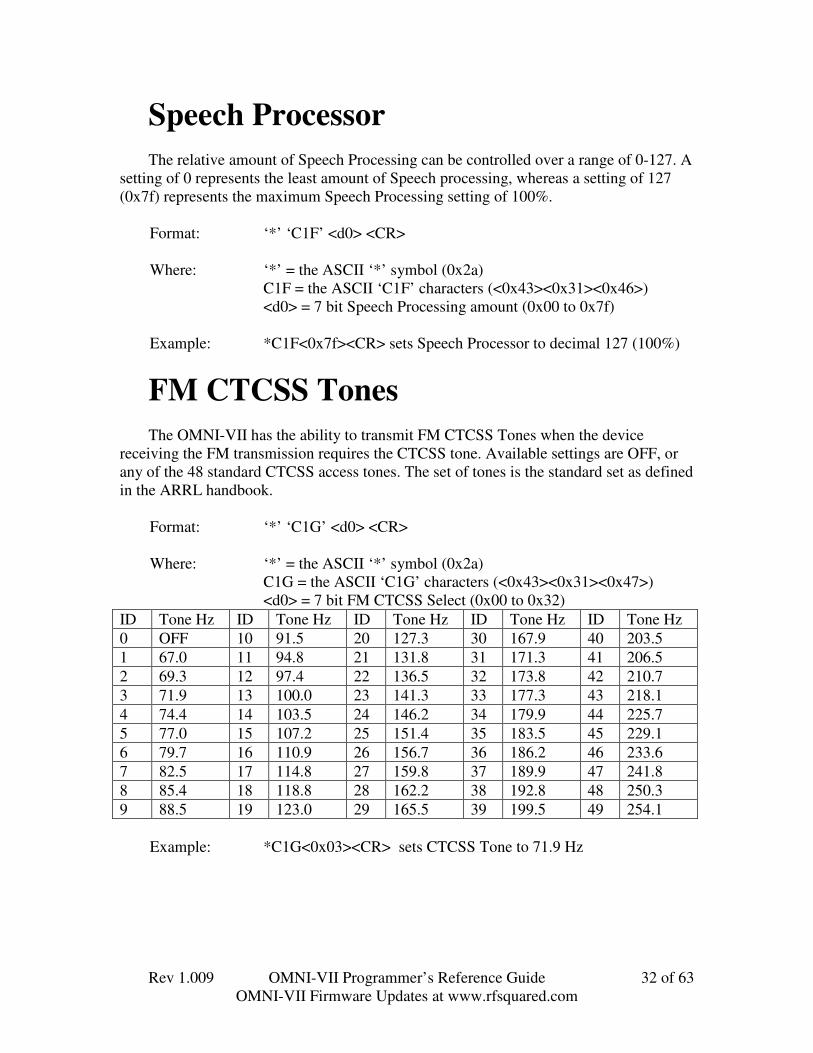
Speech ProcessorThe relative amount of Speech Processing can be controlled over a range of 0-127. A
setting of 0 represents the least amount of Speech processing, whereas a setting of 127(0x7f) represents the maximum Speech Processing setting of 100%.
Format: ‘*’ ‘C1F’ <d0> <CR>
Where: ‘*’ = the ASCII ‘*’ symbol (0x2a)C1F = the ASCII ‘C1F’ characters (<0x43><0x31><0x46>)<d0> = 7 bit Speech Processing amount (0x00 to 0x7f)
Example: *C1F<0x7f><CR> sets Speech Processor to decimal 127 (100%)
FM CTCSS TonesThe OMNI-VII has the ability to transmit FM CTCSS Tones when the device
receiving the FM transmission requires the CTCSS tone. Available settings are OFF, orany of the 48 standard CTCSS access tones. The set of tones is the standard set as definedin the ARRL handbook.
Format: ‘*’ ‘C1G’ <d0> <CR>
Where: ‘*’ = the ASCII ‘*’ symbol (0x2a)C1G = the ASCII ‘C1G’ characters (<0x43><0x31><0x47>)<d0> = 7 bit FM CTCSS Select (0x00 to 0x32)
ID Tone Hz ID Tone Hz ID Tone Hz ID Tone Hz ID Tone Hz0 OFF 10 91.5 20 127.3 30 167.9 40 203.51 67.0 11 94.8 21 131.8 31 171.3 41 206.52 69.3 12 97.4 22 136.5 32 173.8 42 210.73 71.9 13 100.0 23 141.3 33 177.3 43 218.14 74.4 14 103.5 24 146.2 34 179.9 44 225.75 77.0 15 107.2 25 151.4 35 183.5 45 229.16 79.7 16 110.9 26 156.7 36 186.2 46 233.67 82.5 17 114.8 27 159.8 37 189.9 47 241.88 85.4 18 118.8 28 162.2 38 192.8 48 250.39 88.5 19 123.0 29 165.5 39 199.5 49 254.1
Example: *C1G<0x03><CR> sets CTCSS Tone to 71.9 Hz

Rev 1.009 OMNI-VII Programmer’s Reference Guide 33 of 63OMNI-VII Firmware Updates at www.rfsquared.com
RX EqualizerThe RX Equalizer is selectable in 1-dB steps from high pitched at –20 to essentially
flat response at 0dB to very bassy at +20dB. These 41 steps are controlled over a range of0-127. A setting of 0 represents the –20dB selection, a setting of 63 (0x3f) represents theflat response of 0dB, and a setting of 127 represents the +20dB selection.
Format: ‘*’ ‘C1H’ <d0> <CR>
Where: ‘*’ = the ASCII ‘*’ symbol (0x2a)C1H = the ASCII ‘C1H’ characters (<0x43><0x31><0x48>)<d0> = 7 bit RX Equalizer setting (0x00 to 0x7f)
Example1: *C1H<0x7f><CR> sets RX Equalizer to 100% = +20dB
Example2: *C1H<0x3f><CR> sets RX Equalizer to 50% = 0dBNote: The conversion factor used in the OMNI-VII is 3.097560975 to convert 0..127
into 0..41 which represents –20dB to 20dB
TX EqualizerThe TX Equalizer is selectable in 1-dB steps from high pitched at –20 to essentially
flat response at 0dB to very bassy at +20dB. These 41 steps are controlled over a range of0-127. A setting of 0 represents the –20dB selection, a setting of 63 (0x3f) represents theflat response of 0dB, and a setting of 127 represents the +20dB selection.
Format: ‘*’ ‘C1I’ <d0> <CR>
Where: ‘*’ = the ASCII ‘*’ symbol (0x2a)C1I = the ASCII ‘C1I’ characters (<0x43><0x31><0x49>)<d0> = 7 bit TX Equalizer setting (0x00 to 0x7f)
Example1: *C1I<0x7f><CR> sets TX Equalizer to 100% = +20dB
Example2: *C1I<0x00><CR> sets TX Equalizer to 0% = -20dBNote: The conversion factor used in the OMNI-VII is 3.097560975 to convert 0..127
into 0..41 which represents –20dB to 20dB.

Rev 1.009 OMNI-VII Programmer’s Reference Guide 34 of 63OMNI-VII Firmware Updates at www.rfsquared.com
Transmit Roll OffThe Transmit Roll Off can be set to 70-300Hz. This determine shwere the low end
frequency responses of an SSB transmit signal begins to attenuate.
Format: ‘*’ ‘C1J’ <d0> <CR>
Where: ‘*’ = the ASCII ‘*’ symbol (0x2a)C1J = the ASCII ‘C1J’ characters (<0x43><0x31><0x4A>)<d0> = 7 bit transmit roll off select (0x00 to 0x17)
Example: *C1J<0x10><CR> sets Transmit Roll Off to decimal 127 (100%)
ID RollOff ID RollOff ID RollOff ID RollOff ID RollOff0 70 5 120 10 170 15 220 20 2701 80 6 130 11 180 16 230 21 2802 90 7 140 12 190 17 240 22 2903 100 8 150 13 200 18 250 23 3004 110 9 160 14 210 19 260
Example1: *C1J<0x03><CR> sets Transmit Roll Off to 100Hz
Example2: *C1J<0x00><CR> sets Transmit Roll Off to 70Hz
External T/R DelayThe External T/R Delay gives the operator the ability to keep the amplifier keyed
longer. The value is selectable from 0 giving around a 15mS delay to 127 giving arounda 1 second delay.
Format: ‘*’ ‘C1K’ <d0> <CR>
Where: ‘*’ = the ASCII ‘*’ symbol (0x2a)C1K = the ASCII ‘C1K’ characters (<0x43><0x31><0x4B>)<d0> = 7 bit External T/R Delay Selection (0x00 to 0x7f)
Example1: *C1K<0x7f><CR> sets External T/R Delay to 100%
Example2: *C1K<0x00><CR> sets External T/R Delay to 0%

Rev 1.009 OMNI-VII Programmer’s Reference Guide 35 of 63OMNI-VII Firmware Updates at www.rfsquared.com
Sidetone FrequencyThe Sidetone Frequency can be set to 0-1270Hz in 10 Hz steps.
Format: ‘*’ ‘C1L’ <d0> <CR>
Where: ‘*’ = the ASCII ‘*’ symbol (0x2a)C1L = the ASCII ‘C1L’ characters (<0x43><0x31><0x4C>)<d0> = 7 bit Sidetone Frequency Selection (0x00 to 0x7f)
Example1: *C1L<0x64><CR> sets Sidetone Frequency to 1000 Hz
Example2: *C1L<0x28><CR> sets Sidetone Frequency to 400 Hz
CW QSK DelayThe CW QSK Delay adjusts the amount of time it takes for receive audio to be
restored after finishing transmission of a CW dit/dah. The range is from 0, for full breakin, up to 127 for maximum delay of about 1 second time. This control does not hold offthe next transmit. Only sets the time that the next receive will be enabled providing thatanother transmit doesn’t start during that timeframe.
Format: ‘*’ ‘C1M’ <d0> <CR>
Where: ‘*’ = the ASCII ‘*’ symbol (0x2a)C1M = the ASCII ‘C1M’ characters (<0x43><0x31><0x4D>)<d0> = 7 bit CW QSK Delay Selection (0x00 to 0x7f)
Example1: *C1M<0x7f><CR> sets CW QSK Delay to 100% (1 second)
Example2: *C1M<0x00><CR> sets CW QSK Delay to 0% (full break-in)

Rev 1.009 OMNI-VII Programmer’s Reference Guide 36 of 63OMNI-VII Firmware Updates at www.rfsquared.com
Transmit EnableThis controls whether attempts to transmit will produce RF or not. It is possible to
practice CW, listen to the sidetone, and not transmit. The range is from 0 for transmitterdisabled, to 1 for transmitter enabled.
Format: ‘*’ ‘C1N’ <d0> <CR>
Where: ‘*’ = the ASCII ‘*’ symbol (0x2a)C1N = the ASCII ‘C1N’ characters (<0x43><0x31><0x4E>)<d0> = binary 0 for Transmitter Disable
= binary 1 for Transmitter Enable
Example: *C1N<0x00><CR> disables the transmitter RF output
Rev 1.009 OMNI-VII Programmer’s Reference Guide 37 of 63OMNI-VII Firmware Updates at www.rfsquared.com
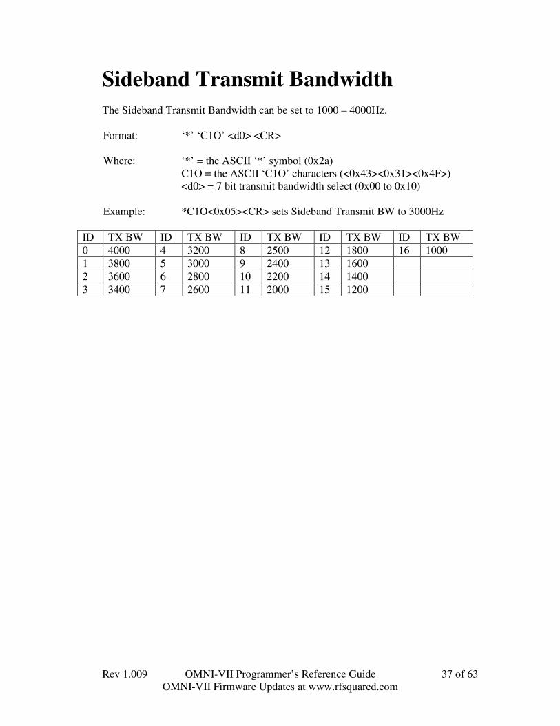
Sideband Transmit BandwidthThe Sideband Transmit Bandwidth can be set to 1000 – 4000Hz.
Format: ‘*’ ‘C1O’ <d0> <CR>
Where: ‘*’ = the ASCII ‘*’ symbol (0x2a)C1O = the ASCII ‘C1O’ characters (<0x43><0x31><0x4F>)<d0> = 7 bit transmit bandwidth select (0x00 to 0x10)
Example: *C1O<0x05><CR> sets Sideband Transmit BW to 3000Hz
ID TX BW ID TX BW ID TX BW ID TX BW ID TX BW0 4000 4 3200 8 2500 12 1800 16 10001 3800 5 3000 9 2400 13 16002 3600 6 2800 10 2200 14 14003 3400 7 2600 11 2000 15 1200
Rev 1.009 OMNI-VII Programmer’s Reference Guide 38 of 63OMNI-VII Firmware Updates at www.rfsquared.com
Auto TunerThis controls whether the OMNI-VII will control the optional Auto Tuner or not. It
is possible to have an Auto Tuner installed, yet you may want to force it to not use theAuto Tuner under certain conditions. The range is from 0 for Auto Tuner Not Installed, to1 for Auto Tuner Installed. Not Installed forces the OMNI-VII to send the Auto TunerBypass control to the Auto Tuner, making sure that it is bypassed.
Format: ‘*’ ‘C1P’ <d0> <CR>
Where: ‘*’ = the ASCII ‘*’ symbol (0x2a)C1P = the ASCII ‘C1P’ characters (<0x43><0x31><0x50>)<d0> = binary 0 for Auto Tuner Not Installed
= binary 1 for Auto Tuner Installed
Example: *C1P<0x00><CR> Disables using the Auto Tuner.
Sidetone VolumeThe relative Sidetone Volume can be controlled over a range of 0-127. A setting of 0
represents Sidetone Off, whereas a setting of 127 (0x7f) represents the maximumSidetone Volume setting of 100%.
Format: ‘*’ ‘C1Q’ <d0> <CR>
Where: ‘*’ = the ASCII ‘*’ symbol (0x2a)C1Q = the ASCII ‘C1Q’ characters (<0x43><0x31><0x51>)<d0> = 7 bit sidetone volume selection (0x00 to 0x7f)
Example: *C1Q<0x3f><CR> sets Sidetone Volume to decimal 63 (50%)

Rev 1.009 OMNI-VII Programmer’s Reference Guide 39 of 63OMNI-VII Firmware Updates at www.rfsquared.com
SPOT VolumeThe relative SPOT Volume can be controlled over a range of 0-127. A setting of 0
represents SPOT Off, whereas a setting of 127 (0x7f) represents the maximum SPOTVolume setting of 100%.
Format: ‘*’ ‘C1R’ <d0> <CR>
Where: ‘*’ = the ASCII ‘*’ symbol (0x2a)C1R = the ASCII ‘C1R’ characters (<0x43><0x31><0x52>)<d0> = 7 bit SPOT volume selection (0x00 to 0x7f)
Example: *C1R<0x3f><CR> sets SPOT Volume to decimal 63 (50%)
FSK Mark High/LowThis controls whether the OMNI-VII will transmit the MARK at High or at Low
Frequency. The range is from 0 for Mark Low, to 1 for Mark High. The High Frequencyis the frequency displayed in the transmit frequency, and the Low Frequency is 170Hzlower. The Mark/Space selection is via the rear input pins in the acc port.
Format: ‘*’ ‘C1S’ <d0> <CR>
Where: ‘*’ = the ASCII ‘*’ symbol (0x2a)C1S = the ASCII ‘C1S’ characters (<0x43><0x31><0x53>)<d0> = binary 0 for Mark Low Frequency
= binary 1 for Mark High Frequency
Example: *C1S<0x01><CR> Enables using the Mark at the High Frequency
Rev 1.009 OMNI-VII Programmer’s Reference Guide 40 of 63OMNI-VII Firmware Updates at www.rfsquared.com
I-F Filter SelectionThe I-F Filter can be selected from 20kHz to 300Hz or even Automatic Selection
based on the Receive Bandwidth selection.
Format: ‘*’ ‘C1T’ <d0> <CR>
Where: ‘*’ = the ASCII ‘*’ symbol (0x2a)C1T = the ASCII ‘C1T’ characters (<0x43><0x31><0x54>)<d0> = binary 0 = 20kHz = binary 1 = 6kHz
= binary 2 = 2.5kHz = binary 3 = 500kHz= binary 4 = 300Hz = binary 5 = Auto
Example1: *C1T<0x02><CR> sets I-F Selected to 2.5kHz
Note: the query returns two bytes. The first is the “I-F Selected”, the second is theactual “I-F In Use”. So you can see the user selection and the actual current statuswith the ?C1T Query. Follows same format for d0 as shown above.
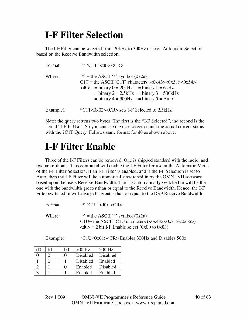
I-F Filter EnableThree of the I-F Filters can be removed. One is shipped standard with the radio, and
two are optional. This command will enable the I-F Filter for use in the Automatic Modeof the I-F Filter Selection. If an I-F Filter is enabled, and if the I-F Selection is set toAuto, then the I-F Filter will be automatically switched in by the OMNI-VII softwarebased upon the users Receive Bandwidth. The I-F automatically switched in will be theone with the bandwidth greater than or equal to the Receive Bandwidth. Hence, the I-FFilter switched in will always be greater than or equal to the DSP Receive Bandwidth.
Format: ‘*’ ‘C1U <d0> <CR>
Where: ‘*’ = the ASCII ‘*’ symbol (0x2a)C1U= the ASCII ‘C1U characters (<0x43><0x31><0x55>)<d0> = 2 bit I-F Enable select (0x00 to 0x03)
Example: *C1U<0x01><CR> Enables 300Hz and Disables 500z
d0 b1 b0 500 Hz 300 Hz0 0 0 Disabled Disabled1 0 1 Disabled Enabled2 1 0 Enabled Disabled3 1 1 Enabled Enabled

Rev 1.009 OMNI-VII Programmer’s Reference Guide 41 of 63OMNI-VII Firmware Updates at www.rfsquared.com
AntennaThe OMNI-VII has connections for two HF Transceiver Antennas, and one HF
Receiver Antenna. These are referred to as ANT1, ANT2, and RXAUX on the radioselection menus.
Format: ‘*’ ‘C1V <d0> <CR>
Where: ‘*’ = the ASCII ‘*’ symbol (0x2a)C1V= the ASCII ‘C1V characters (<0x43><0x31><0x56>)<d0> = binary 0 = RX=TX=ANT1
= binary 1 = RX=TX=ANT2= binary 2 = RX=RXAUX, TX=ANT1= binary 3 = RX=RXAUX, TX=ANT2
Example1: *C1V0<CR> sets Receive and Transmit to ANT1
Example2: *C1V2<CR> sets Receive to RXAUX and Transmit to ANT1
MonitorThe relative Monitor can be controlled over a range of 0-127. A setting of 0
represents Monitor Off, whereas a setting of 127 (0x7f) represents the maximum Monitorsetting of 100%.
Format: ‘*’ ‘C1W’ <d0> <CR>
Where: ‘*’ = the ASCII ‘*’ symbol (0x2a)C1W = the ASCII ‘C1W’ characters (<0x43><0x31><0x57>)<d0> = 7 bit Monitor selection (0x00 to 0x7f)
Example: *C1W<0x3f><CR> sets Monitor to decimal 63 (50%)
Rev 1.009 OMNI-VII Programmer’s Reference Guide 42 of 63OMNI-VII Firmware Updates at www.rfsquared.com
Transmit PowerThe relative Transmit Power can be controlled over a range of 0-127. A setting of 0
represents lowest power setting, and 127 (0x7f) represents maximum transmit powerlevel. The OMNI-VII allows you to select 0…127, which represents 0..100 Watts.However, the lower value will be limited to no lower than 5Watts.
Format: ‘*’ ‘C1X’ <d0> <CR>
Where: ‘*’ = the ASCII ‘*’ symbol (0x2a)C1X = the ASCII ‘C1X’ characters (<0x43><0x31><0x58>)<d0> = 7 bit Power selection (0x00 to 0x7f)
Example: *C1X<0x3f><CR> sets Power to decimal 63 (50% = 50Watts)
Note: the query returns the power selected, plus the current forward power andreflected power.
Example: ?C1X<CR> from Computer to OMNI-VII queries the PowerSetting
Returns: C1X<0x3f><0x3e><0x03><CR> means the OMNI-VII is selectedto transmit 50 watts, has forward power slightly less than 50 watts,and has reflected power of 3/127*100 approx 2.36 watts reflected.
SPOT Tone On/OffThis controls whether the OMNI-VII will generate the SPOT Tone. The range is
from 0 for SPOT Tone OFF, to 1 for SPOT Tone ON.
Format: ‘*’ ‘C1Y’ <d0> <CR>
Where: ‘*’ = the ASCII ‘*’ symbol (0x2a)C1Y = the ASCII ‘C1Y’ characters (<0x43><0x31><0x59>)<d0> = binary 0 for SPOT Tone Off
= binary 1 for SPOT Tone On
Example: *C1Y<0x01><CR> Turns ON SPOT Tone.

Rev 1.009 OMNI-VII Programmer’s Reference Guide 43 of 63OMNI-VII Firmware Updates at www.rfsquared.com
PREAmp On/OffThis controls whether the OMNI-VII will engage the Pre-Amplifier or not. The range
is from 0 for Pre-Amplifier OFF, to 1 for Pre-Amplifier ON.
Format: ‘*’ ‘C1Z’ <d0> <CR>
Where: ‘*’ = the ASCII ‘*’ symbol (0x2a)C1Z = the ASCII ‘C1Z’ characters (<0x43><0x31><0x5A>)<d0> = binary 0 for PreAmp Off
= binary 1 for PreAMp On
Example: *C1Z<0x01><CR> Turns the Pre-Amplifier ON.
Remote TuneThe OMNI-VII can be told to enter the TUNING state or exit the TUNING state by
sending this command. There are no parameters for this command. Once initiated, theOMNI-VII performs exactly the same functions as if you had pushed the TUNE buttonlocally. It is best for your application to send this command, and then read thecorresponding query until the status shows that the TUNE cycle is complete.
Format: ‘*’ ‘C2A’ <CR>
Where: ‘*’ = the ASCII ‘*’ symbol (0x2a)C2A = the ASCII ‘C2A’ characters (<0x43><0x32><0x41>)
Example: *C2A<CR> Tells the OMNI-VII to start its tuning cycleExample: *C2A<CR> Tells the OMNI-VII to start its tuning cycle
*C2A <CR> if the OMNI-VII is manually tuning, then thiscommand will tell it to stop tuning.
Query Format: ?C2A<CR>Radio Returns: C2A <d0> <CR>
Where: <d0> = bit 0 = 0 => Auto Tuner Not Enabled= 1 => Auto Tuner Enabled
= bit 1 = 0 => Not Currently Tuning= 1 => Currently Tuning
= bit 2 = 0 => Not Tuned / = Bypassed= 1 => Tuned

Rev 1.009 OMNI-VII Programmer’s Reference Guide 44 of 63OMNI-VII Firmware Updates at www.rfsquared.com
Split State – Extended FormatSplit State Selection in REMOTE MODE is available in the same command format
as in RADIO MODE using the *N ?N command query. Split State is also adjustable inthe extended command set as follows: (This extended command gives no additionalfunctionality over the N command. Only supported because existing programs use theextended format, and the radio command was added to support other programs)
Format: ‘*’ ‘C2B’ <d0> <CR>
Where: ‘*’ = the ASCII ‘*’ symbol (0x2a)C2B = the ASCII ‘C2B’ characters (<0x43><0x32><0x42>)<d0> = 0 = SPLIT OFF
= 1 = SPLIT ON
Example: *C2B<0x00><CR> turns off SPLIT state
VOX TRIP LevelThe relative VOX Trip Level can be controlled over a range of 0-127. A setting of 0
represents lowest Trip setting, and 127 (0x7f) represents maximum Trip level.
Format: ‘*’ ‘C2C’ <d0> <CR>
Where: ‘*’ = the ASCII ‘*’ symbol (0x2a)C2C = the ASCII ‘C2C’ characters (<0x43><0x32><0x43>)<d0> = 7 bit VOX Trip selection (0x00 to 0x7f)
Example: *C2C<0x3f><CR> sets VOX Trip to decimal 63 (50%)

Rev 1.009 OMNI-VII Programmer’s Reference Guide 45 of 63OMNI-VII Firmware Updates at www.rfsquared.com
ANTI VOX LevelThe relative ANTI VOX Level can be controlled over a range of 0-127. A setting of
0 represents lowest Anti-VOX setting, and 127 (0x7f) represents maximum Anti-VOX.
Format: ‘*’ ‘C2D’ <d0> <CR>
Where: ‘*’ = the ASCII ‘*’ symbol (0x2a)C2D = the ASCII ‘C2D’ characters (<0x43><0x32><0x44>)<d0> = 7 bit Anti-VOX selection (0x00 to 0x7f)
Example: *C2D<0x3f><CR> sets Anti VOX to decimal 63 (50%)
VOX Hang TimeThe relative VOX Hang Time can be controlled over a range of 0-127. A setting of
0 represents lowest VOX Hang Time, and 127 (0x7f) represents maximum VOX Hang.
Format: ‘*’ ‘C2E’ <d0> <CR>
Where: ‘*’ = the ASCII ‘*’ symbol (0x2a)C2E = the ASCII ‘C2E’ characters (<0x43><0x32><0x45>)<d0> = 7 bit VOX Hang Time selection (0x00 to 0x7f)
Example: *C2E<0x3f><CR> sets VOX Hang Time to decimal 63 (50%)
Rev 1.009 OMNI-VII Programmer’s Reference Guide 46 of 63OMNI-VII Firmware Updates at www.rfsquared.com
CW Keyer ModeThis controls whether the OMNI-VII internal keyer mode operates in Mode A or
Mode B mode, or OFF
Format: ‘*’ ‘C2F’ <d0> <CR>
Where: ‘*’ = the ASCII ‘*’ symbol (0x2a)C2F = the ASCII ‘C2F’ characters (<0x43><0x32><0x56>)<d0> b0 = Curtis Mode A
b1 = Curtis Mode Bb2 = Internal Keyer ON/Off
Example1: *C2F<0x01><CR> Sets to Curtis Mode A, Internal Keyer OFFThis is legal, means that the internal keyer mode is off, but ifchanged to
Example2: *C2F<0x06><CR> Sets to Curtis Mode B, Internal Keyer ON
CW Keyer WeightingThe relative CW Keyer Weighting can be controlled over a range of 0-127. A
setting of 0 represents lowest CW Keyer Weighting Time, and 127 (0x7f) representsmaximum CW Keyer Weighting Time. For firmware version 1.022 onwards, thisrepresents weighting of 0 to 50%. Prior firmware versions this was 0 to 24%.
Format: ‘*’ ‘C2G’ <d0> <CR>
Where: ‘*’ = the ASCII ‘*’ symbol (0x2a)C2G = the ASCII ‘C2G’ characters (<0x43><0x32><0x47>)<d0> = 7 bit CW Keyer Weighting selection (0x00 to 0x7f)
Example: *C2G<0x7f><CR> sets CW Keyer Weighting to decimal 63(50%)
Rev 1.009 OMNI-VII Programmer’s Reference Guide 47 of 63OMNI-VII Firmware Updates at www.rfsquared.com
Manual NOTCH On/OffThis controls whether the OMNI-VII Manual Notch is engaged or not.
Format: ‘*’ ‘C2H’ <d0> <CR>
Where: ‘*’ = the ASCII ‘*’ symbol (0x2a)C2H = the ASCII ‘C2H’ characters (<0x43><0x32><0x48>)<d0> = binary 0 = Manual Notch OFF
= binary 1 = Manual Notch ON
Example: *C2H<0x01><CR> Turns ON Manual Notch
Manual NOTCH Center FrequencyThe relative Manual NOTCH Center Frequency can be controlled over a range of 0-
127. A setting of 0 represents lowest Manual NOTCH Center Frequency of 20 Hz, and127 (0x7f) represents maximum Manual NOTCH Center Frequency of 4000Hz.
The formula is 40 * MANNCHCF_Selected + 20 Hz
Format: ‘*’ ‘C2I’ <d0> <CR>
Where: ‘*’ = the ASCII ‘*’ symbol (0x2a)C2I = the ASCII ‘C2I’ characters (<0x43><0x32><0x49>)<d0> = 7 bit MANNCHCF_Selected selection (0x00 to 0x7f)
Example: *C2I<0x00><CR> sets Manual Notch Center Frequency to 20Hz
Rev 1.009 OMNI-VII Programmer’s Reference Guide 48 of 63OMNI-VII Firmware Updates at www.rfsquared.com
Manual NOTCH WidthThe relative Manual NOTCH Width can be controlled over a range of 0-127. A
setting of 0 represents lowest Manual NOTCH Width of 10 Hz, and 127 (0x7f) representsmaximum Manual NOTCH Width of 300Hz
The formula is ((315 – 10) / (127 – 1)) * MANNCHWIDTH_Selected Hz
Format: ‘*’ ‘C2J’ <d0> <CR>
Where: ‘*’ = the ASCII ‘*’ symbol (0x2a)C2J = the ASCII ‘C2J’ characters (<0x43><0x32><0x4A>)<d0> = 7 bit MANNCHWIDTH _Selected selection (0x00 to 0x7f)
Example: *C2J<0x00><CR> sets Manual Notch Width to 10Hz
Internal Keyer SpeedThe Internal Keyer Speed can be controlled with a range of 5..63wpm. The data
range is 0..127, meaning that the value sent is Desired_Speed * 127/63. Setting theDesired_Speed to 0 through 4 is ignored in the OMNI-VII and limited to 5wpm.
Format: ‘*’ ‘C2L’ <d0> <CR>
Where: ‘*’ = the ASCII ‘*’ symbol (0x2a)C2L = the ASCII ‘C2L’ characters (<0x43><0x32><0x4C>)<d0> = 7 bit character Desired_Speed
Example1: *C2L<0x0a><CR> sets Desired_Speed to 5 wpm.
Example2: *C2L<0x32><CR> sets Desired_Speed to 25 wpm.
Example3: *C2L<0x64><CR> sets Desired_Speed to 50 wpm.
Example4: *C2L<0x7f><CR> sets Desired_Speed to 63 wpm.
Rev 1.009 OMNI-VII Programmer’s Reference Guide 49 of 63OMNI-VII Firmware Updates at www.rfsquared.com
VOX On/OffVOX can be turned on and off.
Format: ‘*’ ‘C2M’ <d0> <CR>
Where: ‘*’ = the ASCII ‘*’ symbol (0x2a)C2M = the ASCII ‘C2M’ characters (<0x43><0x32><0x4D>)<d0> = binary 0 = VOX OFF
= binary 1 = VOX ON
Example1: *C2M<0x00><CR> sets VOX Off
Example2: *C2M<0x01><CR> sets VOX On
RADIO DISPLAY ON/OFFThe Display on the Radio can be turned on and off remotely.
Format: ‘*’ ‘C2N’ <d0> <CR>
Where: ‘*’ = the ASCII ‘*’ symbol (0x2a)C2N = the ASCII ‘C2N’ characters (<0x43><0x32><0x4E>)<d0> = ASCII “0” = Display OFF
= ASCII “1” = Display OFF
Example1: *C2N0<CR> sets Display Off
Example2: *C2N1<CR> sets Display ON

Rev 1.009 OMNI-VII Programmer’s Reference Guide 50 of 63OMNI-VII Firmware Updates at www.rfsquared.com
RADIO SPEAKER ON/OFFThe Speaker on the Radio can be muted remotely. This also affects the external
speaker connected to the SPKR jack on the back of the radio.
Format: ‘*’ ‘C2O’ <d0> <CR>
Where: ‘*’ = the ASCII ‘*’ symbol (0x2a)C2O = the ASCII ‘C2O’ characters (<0x43><0x32><0x4F>)<d0> = ASCII “0” = Unmuted (speaker audio audible)
= ASCII “1” = Muted (speaker audio muted)
Example1: *C2O0<CR> unmutes the internal/external speaker
Example2: *C2O1<CR> mutes the internal/external speaker
NOTE: The headphone audio is still present, and is unaffected by this command.
TRIP GainThe shift level of the TRIP Gain can be adjusted remotely.
Format: ‘*’ ‘C2P’ <d0> <CR>
Where: ‘*’ = the ASCII ‘*’ symbol (0x2a)C2P = the ASCII ‘C2P’ characters (<0x43><0x32><0x50>)<d0> = ASCII “1” .. “9”
Example: *C2P1<CR> sets shift level of the TRIP Gain to 1
Note: The default value for this item is 6. This was the value used in OMNI-VII1.025 firmware before this feature was added in 1.026. If an invalid value is sent tothe OMNI-VII, it will default it back to 6. So it is good practice that when you setthe TRIP level, read it back and verify it is at the value that you had intended.

Rev 1.009 OMNI-VII Programmer’s Reference Guide 51 of 63OMNI-VII Firmware Updates at www.rfsquared.com
The optional 302 Remote Control provides the OMNI-VII with a remote tuningencoder direct frequency keypad and auxiliary function keys. The 302 connects to theREMOTE jack on the back of the OMNI-VII. The additional features provided by the302 are actually contained within the OMNI-VII. The 302 Remote Encoder provides thephysical knob, switches and encoder, while firmware in the OMNI-VII processes theinput.
The OMNI-VII in REMOTE mode can be placed into a POD-PASSTHRU mode.This instructs the OMNI-VII to not operate on the key presses or encoder turns of the 302Remote pod, but instead will pass them through to the Host PC via the Serial Interface.
To get into this mode, the Host PC can send a POD PASSTHRU command to theOMNI-VII. This command can either turn on or off POD PASSTHRU mode on theremote mode OMNI-VII.
Format: ‘*’ ‘Q’ <d0> <CR>
Where: ‘*’ = the ASCII ‘*’ symbol (0x2a)Q = the ASCII ‘Q’ character (0x51)<d0> = binary 0 to turn OFF POD PASSTHRU mode
= binary 1 to turn ON POD PASSTHRU mode
Example: *Q<0x01><CR> Turns on POD PASSTHRU Mode.
From then on, any Pod Key presses detected by the OMNI-VII will be sent in a PODPASSTHRU Notification on the serial port to a host PC. Any Pod Encoder turns detectedby the OMNI-VII will be sent in a POD ENCODER Notification on the serial port to ahost PC. A notification occurs for a key press, and a notification occurs for a key release.The design of the 302 prevents the activation of multiple keys and keys are non-repeating.
Operation with Optional 302Remote Encoder
POD PASSTHRU Command

Rev 1.009 OMNI-VII Programmer’s Reference Guide 52 of 63OMNI-VII Firmware Updates at www.rfsquared.com
The format of the POD PASSTHRU Notification from the OMNI-VII to thecomputer via the serial port that a POD key has been pressed/released is as follows:
Format: ‘Q’ <d0> <CR>
Where: Q = the ASCII ‘Q’ character (0x51)<d0> = key press code…
See Diagram Below.If b7 of d0 is low, then the key was depressed.If b7 of d0 is high, then the key was released.
Example1: Q<0x38><CR> means that the “8” key is depressed.
Example2: Q<0xb8><CR> means that the “8” key is released.
Remote KeyLabel
Key PressCode
Remote KeyLabel
Key PressCode
F1 0x11 3 0x33F2 0x12 4 0x34F3 0x13 5 0x35
“.” (Period) 0x2e 6 0x36E 0x0d 7 0x370 0x30 8 0x381 0x31 9 0x392 0x32
POD PASSTHRU Notification

Rev 1.009 OMNI-VII Programmer’s Reference Guide 53 of 63OMNI-VII Firmware Updates at www.rfsquared.com
The format of the POD ENCODER Notification from the OMNI-VII to the computervia the serial port that the POD Encoder has been turned is as follows:
Format: ‘!’ <d0> <CR>
Where: ! = the ASCII ‘!’ character (0x21)<d0> = signed number of encoder turns.
Example1: !<0x01><CR> means that the encoder was turned right one pulse.
Example2: !<0xff><CR> means that the encoder was turned left one pulse.
Note: Due to the architecture of the software within the OMNI-VII, it is highly likelythat you will only ever receive +1 or –1 encoder pulses.
POD ENCODER Notification

Rev 1.009 OMNI-VII Programmer’s Reference Guide 54 of 63OMNI-VII Firmware Updates at www.rfsquared.com
The OMNI-VII provides a way to control devices that are connected to the OMNI-VII’s serial interface, by using the “Serial Pass Thru” command protocol on the Ethernetinterface. It also allows the OMNI-VII to echo back out on the Ethernet Interface, databytes it receives in on the serial interface port, “Serial Echo Mode”. This interfacingmakes it possible to control devices such as Steppir Antenna controllers, seriallycontrolled amplifiers, etc.
The serial port configuration is the same as it is for the command/control protocol:57600 baudNo Parity8 Data Bits1 Stop Bit
This command encapsulates a command stream that will be sent out the OMNI-VII’sserial interface port.
Format: ‘*’ ‘E’ <n> <nn..n1> <CR>E = the ASCII ‘E’ character (0x45)<n> = binary number of items to send in this command
LIMIT of <n> is 11.<nn..n1> = binary the items to send in this command
Range = 0..0xff
Example1: *E<0x04> TEST <CR> Instructs the OMNI-VII to send out on theserial interface port the following command stream “TEST”
Example2: Assume a SteppIR controller is connected to the OMNI-VII SerialPort.*E <0x0B> <<0x40, 0x41, 0x00, 0x20, 0x92, 0xAC, 0x00, 0x40,0x31, 0x30, 0x0D>> <CR> The data stream within the <<>>would instruct the SteppIR to set the antenna to 21.347MHz, 180degrees. Refer to SteppIR interface spec for specifics on this orother commands at the SteppIR web site.
Serial Device Control via Ethernet
Serial Pass Thru

Rev 1.009 OMNI-VII Programmer’s Reference Guide 55 of 63OMNI-VII Firmware Updates at www.rfsquared.com
Serial Echo Mode will enable the OMNI-VII to take bytes received on the serialinterface port and echo them to the Ethernet interface port.
To get into this mode, the Host PC can send a SERIAL_ECHO command to theOMNI-VII. This command can either turn on or off SERIAL_ECHO mode on the remotemode OMNI-VII. This mode is independent of whether Serial Passthru is in effect or not.
Format: ‘*’ ‘D’ <d0> <CR>
Where: ‘*’ = the ASCII ‘*’ symbol (0x2a)D = the ASCII ‘D’ character (0x46)<n> = binary 0 to turn off Serial Echo Mode
= binary 1 to turn ON Serial Echo Mode
Example1: *D<0x01> <CR> Instructs the OMNI-VII to enable Serial EchoMode.
NOTE: There is no query for this command. Once it is turned on, then if any serialdata byte comes in, it will be echoed to the Ethernet port on thissame “D”.
For the following example, assume you have a device Barney connected to theOMNI-VII’s serial port that answers to the query “?H”, with thestring “HELLO”
Example:From PC to OMNI-VII
*D<0x01><CR> (Turns on serial pass echo mode)
From PC to OMNI-VII*E<0x02> ?H <CR> Instructs the OMNI-VII to send out on theserial interface port the following command stream “?H”
From OMNI-VII to Serial Interface Device (Barney)?H
From Barney to OMNI-VII Serial Interface PortH
From OMNI-VII to PC via Ethernet InterfaceEH the E is the query type, the H is the character received.
From Barney to OMNI-VII Serial Interface Port
Serial Echo Mode
Rev 1.009 OMNI-VII Programmer’s Reference Guide 56 of 63OMNI-VII Firmware Updates at www.rfsquared.com
E
From OMNI-VII to PC via Ethernet InterfaceEE
From Barney to OMNI-VII Serial Interface PortL
From OMNI-VII to PC via Ethernet InterfaceEL
From Barney to OMNI-VII Serial Interface PortO
From OMNI-VII to PC via Ethernet InterfaceEO
Rev 1.009 OMNI-VII Programmer’s Reference Guide 57 of 63OMNI-VII Firmware Updates at www.rfsquared.com
The OMNI-VII provides a way to help out with CW transmits in REMOTE mode.The OMNI-VII provides an interface command to send a CW Character. In order for thisto work, the OMNI-VII’s Internal Keyer needs to be turned on, either in Mode A orMode B, and when this command is received, the CW Character will be clocked outgiven the selected CW speed, Rise/Fall, etc. The OMNI-VII One Plug program providesan interface for this feature. There is a CWType window, which is opened by a commandbutton on the OMNI-VII One Plug Console window. When opened, and focus is on theCWType window, keyboard presses are interpreted into CW Characters to send to theOMNI-VII. In turn, if the OMNI-VII is in Remote mode, and if the Internal Keyer isturned on, then the characters will be transmitted out over the air in CW mode.
The OMNI-VII interface supports the standard alpha numeric character set for Athrough Z and 0 through 9. It also supports several special symbols, and some of theserelate to known procedural signals.
Symbol Code group Name Procedural Signal“ .-..-. Quotation mark AF‘ .----. Apostrophe WG( -.--. Open parenthesis KN Back to you) -.--.- Close parenthesis KK+ .-.-. Plus sign AR End of Message* ._… Asterisk/Multiply AS Wait, --..-- Comma MIM- -….- Hyphen or single dash DU. .-.-.- Period AAA/ -..-. Slant/Divide By DN: ---… Colon OS; -.-.-. Semicolon KR= -…- Equal sign BT Separator? ..--.. Question mark IMI@ .--.-. At symbol_ ..--.- Underscore IQ! ---. Exclamation point
> …_._ SK End of contact< .-.- AA All after% -.-.- KA& …-. SN Understood[ .-..- Warning
Note1: The value for each is the ASCII character code for each.
CWType
Rev 1.009 OMNI-VII Programmer’s Reference Guide 58 of 63OMNI-VII Firmware Updates at www.rfsquared.com
Note2: The OMNI-VII handles ascii for upper and lower case characters, andconverts them to the standard dit/dah pattern for that character (e.g. A and a both equaldit dah) So it is not necessary to convert key codes into either upper or lower case makingkeyboard entry possible.
Format: ‘*’ ‘C2K’ <count> CHAR <CR>
Where: ‘*’ = the ASCII ‘*’ symbol (0x2a)C2K = the ASCII ‘C2K’ characters (<0x43><0x32><0x4B>)<count> = binary unique incremental counter for each digit sent
starting = 0, ending = 0xff.Used by radio to know this is a new character.Allows you to send the same character multiple timesto help ensure that the radio gets itEach change in the count means that it is a new character.
CHAR = Ascii Code for the character (0x00 to 0x7f)
Example1: *C2K<0x10>M<CR> tells the OMNI-VII to TX CW Character M*C2K<0x10>M<CR> tells the OMNI-VII to TX CW Character MSince we just got two of the same count, only one M will gettransmitted.
Example2: *C2K<0x11>L<CR> tells the OMNI-VII to TX CW Character L*C2K<0x12>” “<CR> tells the OMNI-VII to TX a word spaceBoth will get carried out, since the count is different.
Only thing the OMNI-VII looks for is that the count is different, ifso, then it will transmit out all characters.
The OMNI-VII does have a cache it will hold characters in, andthe amount of characters left is able to be read via the ?C2Kcommand. It will return a value <d0> which is the count of howmany slots are open.
Example1: ?C2K <CR> query from PC to OMNI-VIIReturns: C2K<0x10> <CR> OMNI-VII states there are 16 slots available in
the CWType ahead buffer.

Rev 1.009 OMNI-VII Programmer’s Reference Guide 59 of 63OMNI-VII Firmware Updates at www.rfsquared.com
The OMNI-VII in REMOTE MODE provides audio over the Ethernet. This is notavailable over the serial interface. This data is packed in a UDP packet.
RIP is the audio that goes from the OMNI-VII to the computer. This is the actualover the air received audio that the OMNI-VII is tuned to receive. This data isencapsulated within a UDP packet with the UDP port numbers set to the UDP CommandPort +2. The command to turn on RIP uses this same UDP Command Port +2 portnumber also. This is required so that the RIP audio sent from the OMNI-VII will make itback to the computer through the hubs and routers.
TRIP is the audio that goes from the computer to the OMNI-VII. This is the actualaudio that is generated by the computer sent to the OMNI-VII over the Ethernet that theOMNI-VII will transmit over the air. This data is encapsulated within a UDP packet withthe UDP port numbers set to the UDP Command Port +4.
Ethernet Audio
RIP (Radio over IP) Introduction
TRIP (Transmit over IP) Introduction

Rev 1.009 OMNI-VII Programmer’s Reference Guide 60 of 63OMNI-VII Firmware Updates at www.rfsquared.com
We do not cover Internet Protocols, please refer to other documents for that. We willcover the data as it pertains to the RIP Audio. The RIP audio is encapsulated in a UDPpacket with the source and destination port numbers set to the UDP Command Port+2.The UDP Packet contains an RTP (Real Time Protocol) format packet that contains theaudio. RTP is the format utilized by various commercial Voice Over IP programsalready. The Header may include most recently measured Signal Strength if in receivemode, or it may include the most recent Transmit power levels. The format of the data isthe same as what is returned in the S Unit and Power Level Queries. The first octet of theHeader Information will indicate if this information is present or if it is standard RTPformat. The format of the data packet used for OMNI-VII RIP is as follows for non-compressed audio:
Octet 0 Header Information 0x80 = RTP FormatVersion -> 2
Padding -> 0 Extension -> 0
OROctet 0 Header Information 0x00 = Includes Signal
Strength or Transmit PowerLevel
Octet 1 Header Information Continued 0x50 Marker -> 0 Payload Type 80d
Octet 2-3 RTP Sequence 0xnn 0xnn Packet Counter (=last+1)
Octet 4-7 RTP TimeStamp 0xnn 0xnn 0xnn 0xnnTime Counter (=last+64)
If Header Information Octet 0 = 0x80 then Octets 8 through 11 are RTP as follows:Octet 8-11 RTP Sync Source 0x45 0xmm 0xnn 0xoo
ID of the Radio (last 4 MAC digits)Otherwise Octets 8 through 11 contain the Signal Strength or Power Levels
“ABCD” of the SUNIT query defined previously in this specification.
Octet 12-139 Audio Data 0xnn…2 Octets => 1 16bit audio
Total of 64 audio wordsFor compressed audio, the packet is of the same length, only difference is that each
byte contains a complete 8 bit audio. 1 Octet => 1 8bit audio. Meaning this is a total of128 audio bytes. The packets will come out at ½ the rate of the non-compressed audio,yielding a lower bandwidth requirement
RIP Audio Packet Format

Rev 1.009 OMNI-VII Programmer’s Reference Guide 61 of 63OMNI-VII Firmware Updates at www.rfsquared.com
The TRIP audio is encapsulated in a UDP packet with the source and destination portnumbers set to the UDP Command Port+4. The UDP Packet only contains a 16 bitcounter and the actual audio to transmit data. The format of the data packet used for theOMNI-VII are as follows for non-compressed TRIP:
Octet 0 Packet Counter 0xxx Packet Counter (=last+1)
Octet 1-129 Audio Data 0xnn…3 Octets => 1 16bit audio
Total of 64 audio wordsFor compressed audio, the packet is of the same length, only difference is that each
byte contains a complete 8 bit audio. 1 Octet => 1 8bit audio. Meaning this is a total of128 audio bytes. The packets will come out at ½ the rate of the non-compressed audio,yielding a lower bandwidth requirement
The Ethernet Command/Query format is basically the same as the Command/Queryprotocol used on the Serial port. The main difference is that for the Etherent, there is alsoa PassCode. The PassCode is 16 bits that precedes the standard Command/Queryprotocol. The PassCode is checked by the OMNI-VII and if it is incorrect, then the packetis ignored.
Format: <p1> <p0> ‘standard command/query protocol’
Where: <p1..p0> = PassCode‘standard command/query protocol’ = as defined in section:
‘The OMNI-VII Command Set ‘Example1: <0x00> <0x04> *A<0x00><0xe4><0xe1><0xc0><CR> sets the
main VFO to 15,000,000 Hz or 15 MHz. Uses PassCode = 4Example2: <0x07> <0xab> *B <0x00><0xe4><0xe1><0xc0><CR> sets the
sub VFO to 15,000,000 Hz or 15 MHz. Uses PassCode = 1963
TRIP Audio Packet Format
Ethernet Command/Query Format
Rev 1.009 OMNI-VII Programmer’s Reference Guide 62 of 63OMNI-VII Firmware Updates at www.rfsquared.com
Date: Revision: ModificationsMarch 7, 2007 1.001 • Modified the Transmit Power to indicate that it
not only returns selected power, but also forwardand reflected power.
• Added “ – REMOTE” or “ – RADIO “ text to theWhere At query.
• Modified S-Unit query to show that it returns s-Units during receive and power values duringtransmits.
• Modified S-Unit query to show two bytes for theSUnit instead of only one byte.
• Modified the Internal Keyer Speed to show thedata value is 0..63wpm => 0..127. The data fieldshould be Desired_Speed * 127/63.
• Added VOX ON/OFF command/query.• Added POD ENCODER Notifications.• Added section on Ethernet Command/Query
Format• Added reference stating that the Ethernet handlers
can be disabled in REMOTE Mode by setting thefirst octet of the G8WAY IPADDR to 0. Providedfor users who control the rig serially in remotemode.
June 5, 2007 1.002 • Made Transmit command *T available in Radiomode also for logging programs
• Added a second Set/Get Split so that the Nvariety is available in Radio mode also forlogging programs. (C2B still supported in Remotemode)
July 19, 2007 1.003 • Added Display On/Off Command• Added Compression Level supported in ?T query• Added Compression Requests to Transmit cmd.• Added reference to 8 bit compression
August 13, 2007 1.004 • Added Speaker On/Off• Added documentation to indicate that the “?*”
command is available to “query all” parameters.September 13, 2007 1.005 • Corrected Mode Values for FM, CWL, and FSK
in “Receive and Transmit Modes” section
Document Revision History

Rev 1.009 OMNI-VII Programmer’s Reference Guide 63 of 63OMNI-VII Firmware Updates at www.rfsquared.com
October 16, 2007 1.006 • Added example showing that the OMNI-VII willlimit the requested frequency if it is out of thesupported range.
• Added notation of change of meaning of CWWeighting from version 1.022 onwards is now0.0x7f = 0 to 50%. Was 0 to 24% for priorversions of firmware.
October 24, 2007 1.007 • Added information on how ?A is handled with thedifferent options for menu item “SERIAL IF”.This will be available in Firmware Revision1.023. Sections modified include:
Frequency Tuning OMNI-VII Command Set Quick List• Added Support for ?RMM for querying mode for
CT Logging program. Sections modified/addedinclude:
OMNI-VII Command Set Quick List Main Mode Query – Orion Format• Added Note to “?C1T” query that it returns the I-
F Filter that is currently in use as a second byte.Sections modified include:
I-F Filter SelectionNovember 29, 2007 1.008 • Modified Serial Pass Thru maximum number of
bytes. Originally stated 21 and but is actually 11.Typo error.
• Corrected Scaling error in documentation for CWKeyer Weighting. A value of 0x7f means 50%weighting.
• Added the format for decoding the SignalStrength and Transmit levels to the RIP DataPacket.
• Added indicator in Version Query to identify ifthe rig has MARS transmit capability or if it isrestricted to ham bands only.
April 23, 2008 1.009 • Modified query for FM CTCSS in the Quick Listto show proper query ?C1G.
• Added TRIP Gain to interface