om, 2007 xrt 900/turf 252/ca 252 (103218315-rev a)xrtdealers.clubcar.com/ownersmanuals/103218315...
TRANSCRIPT
2007Utility
VehiclesGasoline
Owner’s Manual
XRT 900Turf 252
Carryall 252

NOTICE
Warranty information and the California Emission Control Warranty Statement appears on the last pages ofthis manual. No other warranties, express or implied, are contained herein. Your authorized representativechecked the vehicle before it was delivered to you and will provide you a copy of the completed vehicle war-ranty registration form.
Club Car is not liable for errors in this manual or for incidental or consequential damages that result from theuse of the material in this manual.
This manual contains proprietary information that is protected by copyright. All rights are reserved. No part ofthis manual may be photocopied, reproduced, or translated to another language without the written consentof Club Car, Inc.
The information contained in this document is subject to change without notice.
Club Car reserves the right to make design changes to vehicles without obligation to make these changes onunits previously sold.
These vehicles do not conform to Federal Motor Vehicle Safety Standards for automobiles or to FMVSS 500for low-speed vehicles, and are not equipped for operation on public streets, roads, or highways.
P. O. Box 204658Augusta, Georgia 30917-4658 USA
Telephone 706-863-3000Service Parts Fax 706-855-7413
www.clubcar.com
Copyright © 2006 Club Car, Inc.Club Car, PowerDrive, and ArmorFlexare registered trademarks of Club Car, Inc.This manual effective July 31, 2006.
2007 Gasoline Utility Vehicle Owner’s Manual Page 1
FOREWORD
Thank you for choosing Club Car, the name most widely recognized as the industry leader in vehicle efficiencyand long-lasting value. You have chosen the finest utility vehicle on the market. Please protect your invest-ment and ensure that your Club Car vehicle(s) provides years of reliable, superior performance by readingand following the maintenance instructions in this manual.
Your comfort and safety are important to us, so we urge you to read and follow the step-by-step operatinginstructions and safety procedures in this manual. These instructions must be followed in order to avoid therisk of severe personal injury. If you rent or loan your vehicle to others, we recommend that you ask them toread this manual before they operate the vehicle.
Club Car products are backed by a customer support system designed to offer you fast, courteous service. Inthe event that your Club Car vehicle needs repairs or service, we recommend that your local authorized ClubCar representative perform them. For the name and address of the Club Car representative nearest you,logon to our web site at www.clubcar.com or call 1-800-ClubCar (258-2227). If you would prefer to write to us,direct your letter to: Club Car, Attention: Marketing Services, P.O. Box 204658, Augusta, Georgia 30917-4658USA. Your local authorized Club Car representative can also provide technical advice, parts, and servicemanuals.
We hope you will consider this owner’s manual a permanent part of your Club Car vehicle. If you sell the vehi-cle, please include the manual so that the next owner will have the important operating, safety, and mainte-nance information it contains.
Page 2 2007 Gasoline Utility Vehicle Owner’s Manual
TABLE OF CONTENTS
Vehicle Feature Identification .................................................................................................................... 4
Safety Details ............................................................................................................................................ 9
General Warnings ...................................................................................................................................... 10
General Information ................................................................................................................................... 11
Model Identification .................................................................................................................................... 11
Controls and Indicators .............................................................................................................................. 12
Pre-Operation and Daily Safety Checklist ................................................................................................. 16
Performance Inspection ............................................................................................................................. 17
Driving Instructions .................................................................................................................................... 18
Bed Latch .................................................................................................................................................. 20
Prop Rod ................................................................................................................................................... 20
Loading and Unloading .............................................................................................................................. 21
Towing with the Vehicle ............................................................................................................................. 22
Transporting on a Trailer ........................................................................................................................... 23
Storage ...................................................................................................................................................... 23
Maintenance .............................................................................................................................................. 26
Periodic Service Schedule ......................................................................................................................... 26
Periodic Lubrication Schedule ................................................................................................................... 28
Engine Oil .................................................................................................................................................. 29
Fueling Instructions ................................................................................................................................... 31
Battery ....................................................................................................................................................... 32
Cleaning the Vehicle .................................................................................................................................. 34
Accessories ............................................................................................................................................... 34
Subsequent Owner Registration ................................................................................................................ 35
Vehicle Specifications ................................................................................................................................ 36
Rear Fender Installation ............................................................................................................................ 38
Wheel and Tire Installation ........................................................................................................................ 40
2007 Gasoline Utility Vehicle Owner’s Manual Page 3
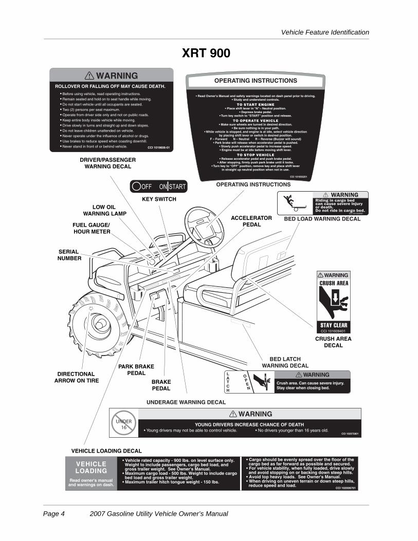
Vehicle Feature Identification
XRT 900
LOW OIL
WARNING LAMP
DRIVER/PASSENGER
WARNING DECAL
FUEL GAUGE/
HOUR METER
KEY SWITCH
SERIAL
NUMBER
CRUSH AREA
DECAL
OPERATING INSTRUCTIONS
BED LATCH
WARNING DECAL
VEHICLE LOADING DECAL
BRAKE
PEDAL
ACCELERATOR
PEDAL
PARK BRAKE
PEDALDIRECTIONAL
ARROW ON TIRE
BED LOAD WARNING DECAL
UNDERAGE WARNING DECAL
Page 4 2007 Gasoline Utility Vehicle Owner’s Manual

Vehicle Feature Identification
XRT 900
CHOKE
FUEL
SHUT-OFF
VALVE
BED LATCH
ROTATING PARTS AND
HOT MANIFOLD DECAL
(ON STARTER/GENERATOR
AND ENGINE)
GASOLINE WARNING DECAL(ON FRAME)
FRAME GROUND AND
GOVERNOR WARNING DECAL(ON FRAME)
TRAILER HITCH
DECAL(ON RECEIVER HITCH)
(ON SEAT SUPPORT PANEL)
WINCH CABLE WARNING DECAL(FOR VEHICLES WITH WINCH ACCESSORY)
(TOP OF PASSENGER SIDE FENDER)
ROTATING PARTS DECAL
DIODE WIRING DECAL
(ON FRAME ABOVE DIODE)
FORWARD/REVERSE
HANDLE (ON DASH)
NEUTRAL LOCKOUT SWITCH DECAL(ON NEUTRAL LOCKOUT BRACKET
UNDER SEAT)
2007 Gasoline Utility Vehicle Owner’s Manual Page 5
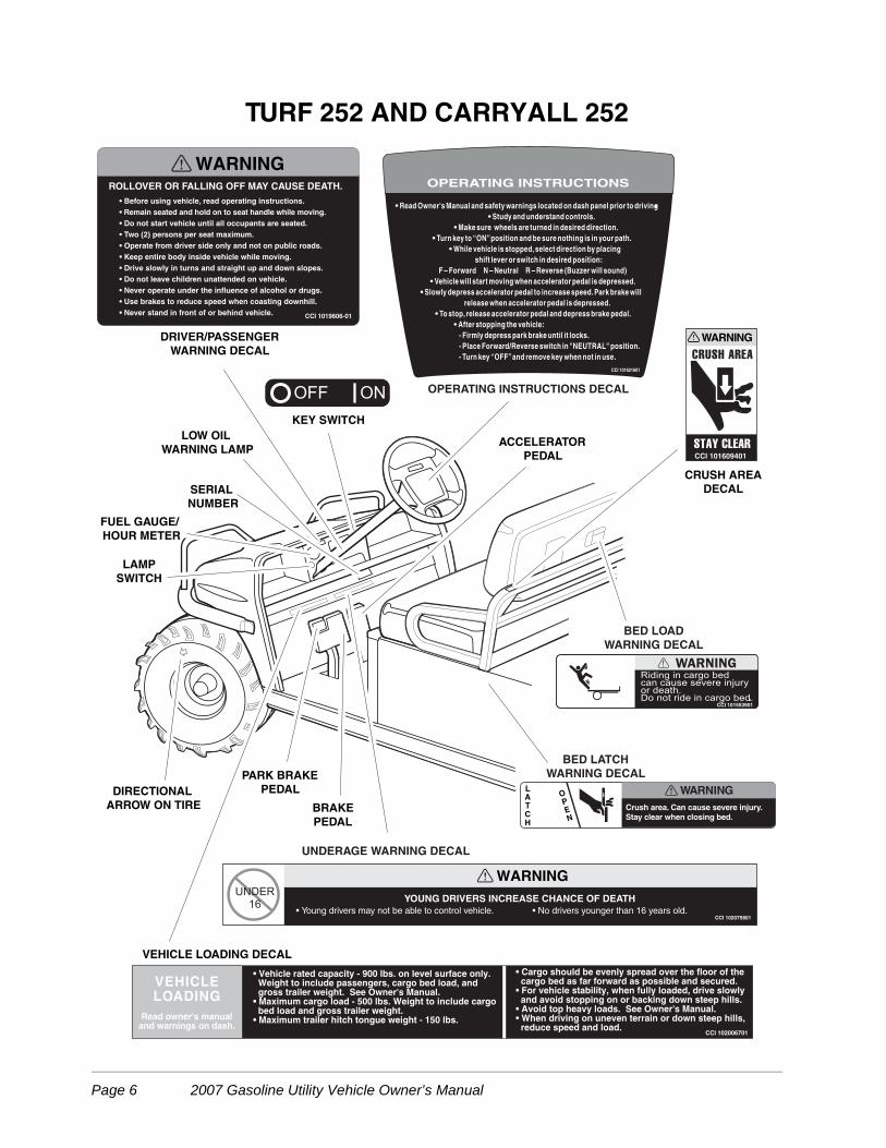
TURF 252 AND CARRYALL 252
Crush area. Can cause severe injury.
Stay clear when closing bed.
LATCH
OPEN
WARNING
CCI 101609401
WARNING
YOUNG DRIVERS INCREASE CHANCE OF DEATH
CCI 102075801• Young drivers may not be able to control vehicle. • No drivers younger than 16 years old.
• Before using vehicle, read operating instructions.
• Remain seated and hold on to seat handle while moving.
• Do not start vehicle until all occupants are seated.
• Two (2) persons per seat maximum.
• Operate from driver side only and not on public roads.
• Keep entire body inside vehicle while moving.
• Drive slowly in turns and straight up and down slopes.
• Do not leave children unattended on vehicle.
• Never operate under the influence of alcohol or drugs.
• Use brakes to reduce speed when coasting downhill.
• Never stand in front of or behind vehicle. CCI 1019606-01
WARNINGROLLOVER OR FALLING OFF MAY CAUSE DEATH.
LOW OIL
WARNING LAMP
DRIVER/PASSENGER
WARNING DECAL
FUEL GAUGE/
HOUR METER
KEY SWITCH
SERIAL
NUMBER
CRUSH AREA
DECAL
OPERATING INSTRUCTIONS DECAL
BED LATCH
WARNING DECAL
VEHICLE LOADING DECAL
BRAKE
PEDAL
ACCELERATOR
PEDAL
PARK BRAKE
PEDALDIRECTIONAL
ARROW ON TIRE
BED LOAD
WARNING DECAL
UNDERAGE WARNING DECAL
LAMP
SWITCH
Page 6 2007 Gasoline Utility Vehicle Owner’s Manual
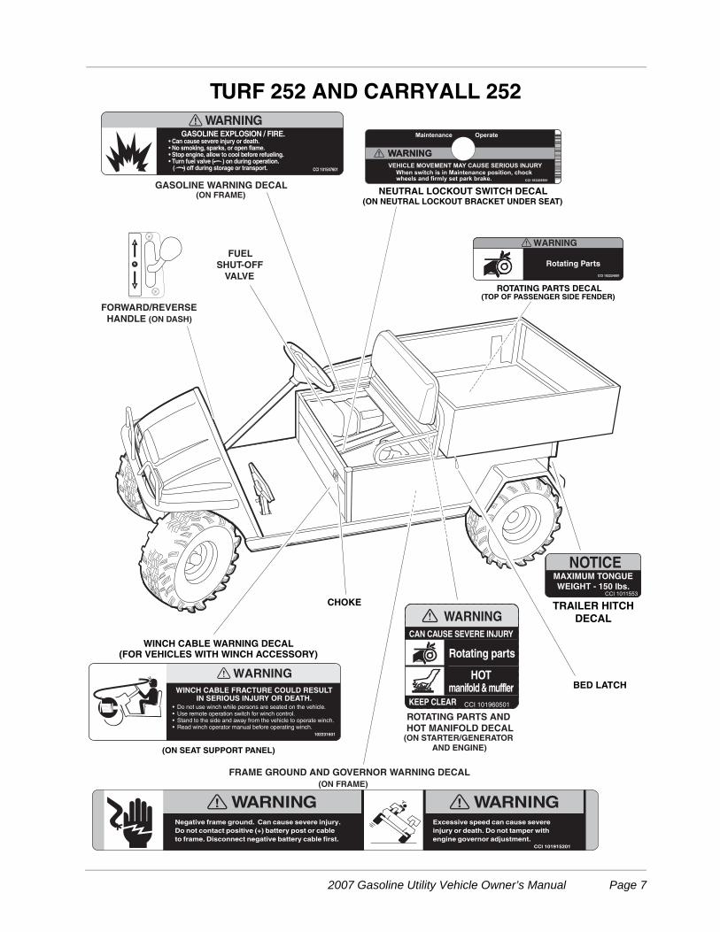
TURF 252 AND CARRYALL 252
CHOKE
FUEL
SHUT-OFF
VALVE
BED LATCH
ROTATING PARTS AND
HOT MANIFOLD DECAL(ON STARTER/GENERATOR
AND ENGINE)
GASOLINE WARNING DECAL(ON FRAME)
FRAME GROUND AND GOVERNOR WARNING DECAL
(ON FRAME)
TRAILER HITCH
DECAL
(ON SEAT SUPPORT PANEL)
WINCH CABLE WARNING DECAL(FOR VEHICLES WITH WINCH ACCESSORY)
(TOP OF PASSENGER SIDE FENDER)ROTATING PARTS DECAL
FORWARD/REVERSE
HANDLE (ON DASH)
NEUTRAL LOCKOUT SWITCH DECAL(ON NEUTRAL LOCKOUT BRACKET UNDER SEAT)
2007 Gasoline Utility Vehicle Owner’s Manual Page 7
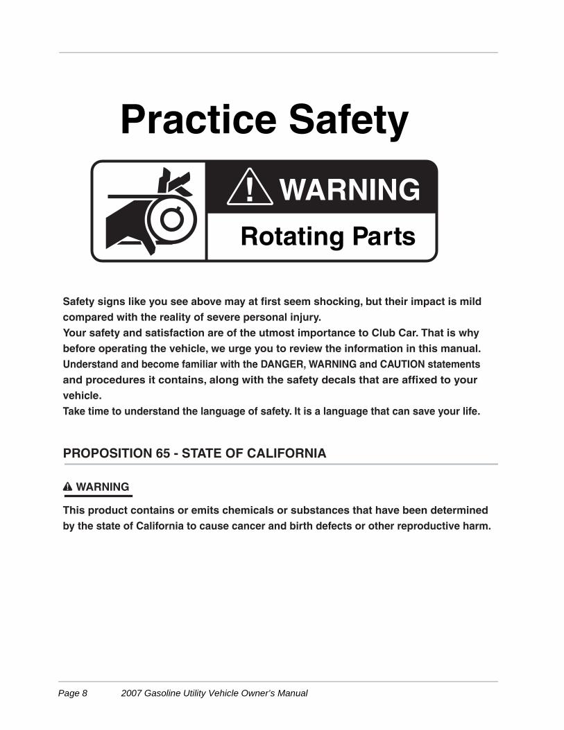
PROPOSITION 65 - STATE OF CALIFORNIA
This product contains or emits chemicals or substances that have been determined
by the state of California to cause cancer and birth defects or other reproductive harm.
! WARNING
Rotating Parts
Practice Safety
Safety signs like you see above may at first seem shocking, but their impact is mild
compared with the reality of severe personal injury.
Your safety and satisfaction are of the utmost importance to Club Car. That is why
before operating the vehicle, we urge you to review the information in this manual.
Understand and become familiar with the DANGER, WARNING and CAUTION statements
and procedures it contains, along with the safety decals that are affixed to your
vehicle.
Take time to understand the language of safety. It is a language that can save your life.
Page 8 2007 Gasoline Utility Vehicle Owner’s Manual
Safety Details
SAFETY DETAILS
ý WARNING
• This owner’s manual should be read completely before attempting to drive or service thevehicle. Failure to follow the instructions in this manual could result in property damage,severe personal injury, or death.
It is important to note that some vital statements throughout this manual and on the decals affixed to the vehi-cle are preceded by the words DANGER, WARNING, or CAUTION. For your protection, we recommend thatyou take special notice of these safety precautions. Safety precautions are essential and must be followed.
If any of the operation or safety decals on the vehicle become damaged, have been removed, or cannot beeasily read, they should be replaced immediately to avoid possible property damage, personal injury, ordeath. Contact your Club Car dealer.
ý DANGER
• A DANGER indicates an immediate hazard that will result in severe personal injury or death.
ý WARNING
• A WARNING indicates an immediate hazard that could result in severe personal injury ordeath.
ý CAUTION
• A CAUTION with the safety alert symbol indicates a hazard or unsafe practice that couldresult in minor personal injury.
CAUTION
• A CAUTION without the safety alert symbol indicates a potentially hazardous situation thatcould result in property damage.
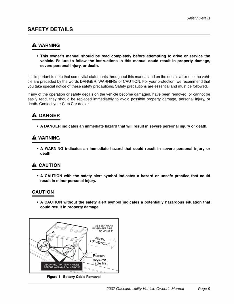
Figure 1 Battery Cable Removal
FRONTOF VEHICLE
AS SEEN FROM
PASSENGER SIDE
OF VEHICLE
Removenegativecable first.DISCONNECT BATTERY CABLES
BEFORE WORKING ON VEHICLE
2007 Gasoline Utility Vehicle Owner’s Manual Page 9
General Warnings
GENERAL WARNINGS
The following safety statements must be heeded whenever the vehicle is being operated, repaired, or ser-viced. Vehicle feature identification information is also included beginning on page 4. Other specific safetystatements appear throughout this manual and on the vehicle.
ý DANGER
• Battery – Explosive gases! Do not smoke. Keep sparks and flames away from the vehicle andservice area. Ventilate when charging or operating vehicle in an enclosed area. Wear a fullface shield and rubber gloves when working on or near batteries.
• Gasoline – Flammable! Explosive! Do not smoke. Keep sparks and flames away from thevehicle and service area. Service only in a well-ventilated area.
• Do not operate gasoline vehicle in an enclosed area without proper ventilation. The engineproduces carbon monoxide, which is an odorless, deadly poison.
• A Club Car vehicle will not provide protection from lightning, flying objects, or other storm-related hazards. If caught in a storm while driving a Club Car vehicle, exit the vehicle and seekshelter in accordance with applicable safety guidelines for your location.
ý WARNING
• Follow the procedures exactly as stated in this manual, and heed all DANGER, WARNING, andCAUTION statements in this manual as well as those on the vehicle.
• Do not leave children unattended on vehicle.
• Prior to leaving the vehicle unattended or servicing the vehicle, set the park brake, place theForward/Reverse handle in the NEUTRAL position, turn the key switch to the OFF position,and remove the key. Chock the wheels when servicing the vehicle.
• Improper use of the vehicle or failure to properly maintain it could result in decreased vehicleperformance, severe personal injury, or death.
• Any modification or change to the vehicle that affects the stability or handling of the vehicle,or increases maximum vehicle speed beyond factory specifications, could result in severepersonal injury or death.
• Check the vehicle for proper location of all vehicle safety and operation decals and make surethey are in place and are easy to read.
• For vehicles with cargo beds, remove all cargo before raising the bed or servicing the vehicle.If the vehicle is equipped with a prop rod, ensure that it is securely engaged while bed israised. Do not close bed until all persons are clear of cargo bed area. Keep hands clear of allcrush areas. Do not drop cargo bed; lower gently and keep entire body clear. Failure to heedthis warning could result in severe personal injury or death.
• Only trained technicians should service or repair the vehicle. Anyone doing even simplerepairs or service should have knowledge and experience in electrical and mechanical repair.The appropriate instructions must be used when performing maintenance, service, oraccessory installation.
• To avoid unintentionally starting the vehicle:
- Disconnect battery cables, negative (–) cable first (Figure 1).
- Disconnect the spark plug wire from the spark plug.
WARNING CONTINUED ON NEXT PAGE...
Page 10 2007 Gasoline Utility Vehicle Owner’s Manual
General Information
ý WARNING
• Frame ground – Do not allow tools or other metal objects to contact frame whendisconnecting battery cables or other electrical wiring. Do not allow a positive wire to touchthe vehicle frame, engine, or any other metal component.
• Wear safety glasses or approved eye protection when servicing the vehicle. Wear a full faceshield and rubber gloves when working on or near batteries.
• Do not wear loose clothing or jewelry such as rings, watches, chains, etc., when servicing thevehicle.
• Use insulated tools when working near batteries or electrical connections. Use extremecaution to avoid shorting of components or wiring.
GENERAL INFORMATION
This manual features gasoline XRT 900, Turf 252, and Carryall 252 vehicles. Throughout this manual, impor-tant vehicle information and features are highlighted. We urge the owner/operator to read and understand thismanual, and to pay special attention to the features specific to his/her vehicle(s).
MODEL IDENTIFICATION
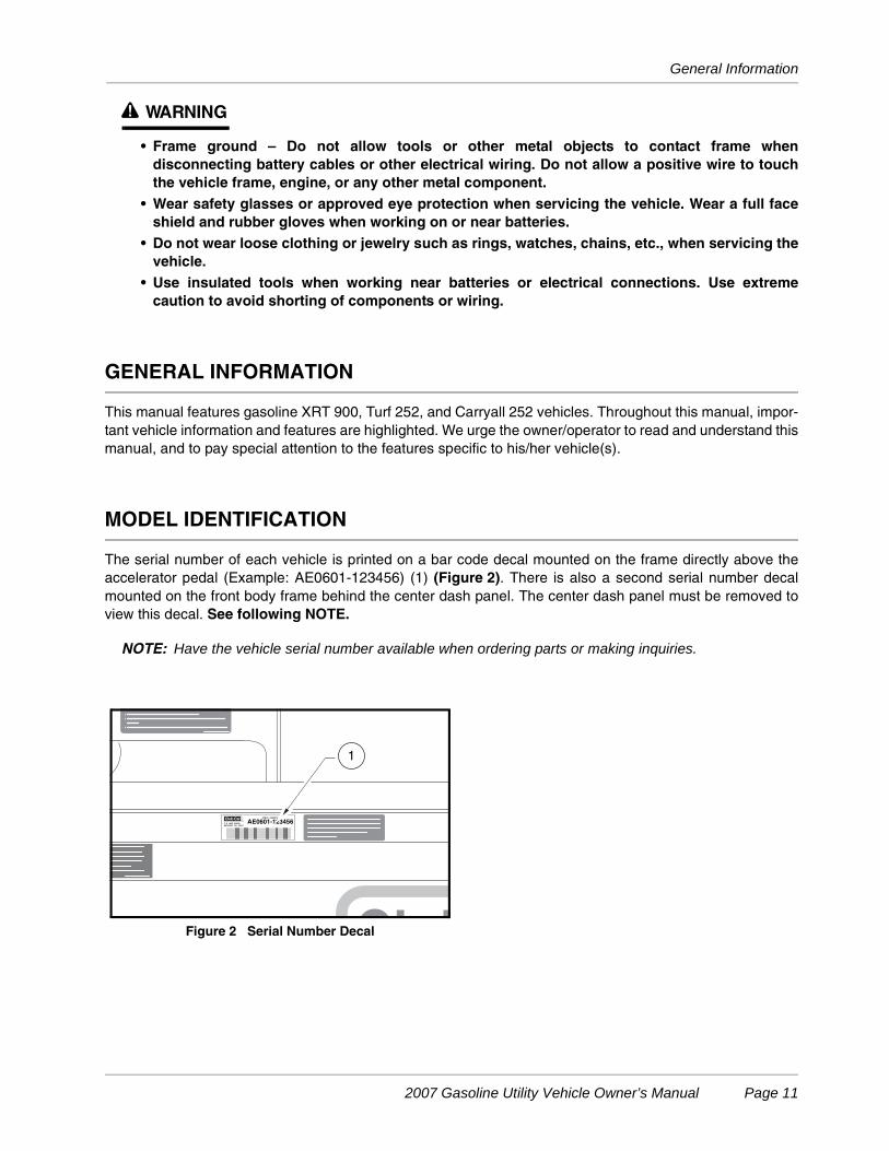
The serial number of each vehicle is printed on a bar code decal mounted on the frame directly above theaccelerator pedal (Example: AE0601-123456) (1) (Figure 2). There is also a second serial number decalmounted on the front body frame behind the center dash panel. The center dash panel must be removed toview this decal. See following NOTE.
NOTE: Have the vehicle serial number available when ordering parts or making inquiries.
Figure 2 Serial Number Decal
SERIAL NUMBER
AE0601-123456P O BOX 204658
AUGUSTA GA 30917
Club CarR
This vehicle is covered by one or more of the
following U.S. Patents as applicable: D271008
D292899, 4343503, 4539162, 4637270, 4821827
4826467, 5042519, 5083736 and other
patents pendings.
1
2007 Gasoline Utility Vehicle Owner’s Manual Page 11
Controls and Indicators
CONTROLS AND INDICATORS
See General Warnings on page 10.
ý WARNING
• Before allowing anyone to drive the vehicle, make sure the driver is familiar with all controlsand operating procedures.
• Do not tamper with the governor. Doing so will void the warranty, as well as damage theengine and other components, and could result in property damage, personal injury, or deathdue to unsafe speeds.
• Do not shift the Forward/Reverse handle while the vehicle is in motion.
• Stop the vehicle before shifting the Forward/Reverse handle. Engine must be at idle beforeshifting the Forward/Reverse handle. Failure to do so may result in injury to inattentivepassengers and (or) damage to the vehicle.
• Release the accelerator pedal and then press the brake pedal firmly until the vehicle stops. Toavoid unintentionally starting or rolling the vehicle, set the park brake, place the Forward/Reverse handle in the NEUTRAL position, turn the key switch to the OFF position, and removethe key when leaving the vehicle.
KEY SWITCH
Each vehicle is equipped with either a two-position key switch or a three-position key switch. Turf 252 and Car-ryall 252 vehicles have a two-position key switch and are referred to as “pedal-start”. The XRT 900 has a three-position key switch and is referred to as “key-start”.
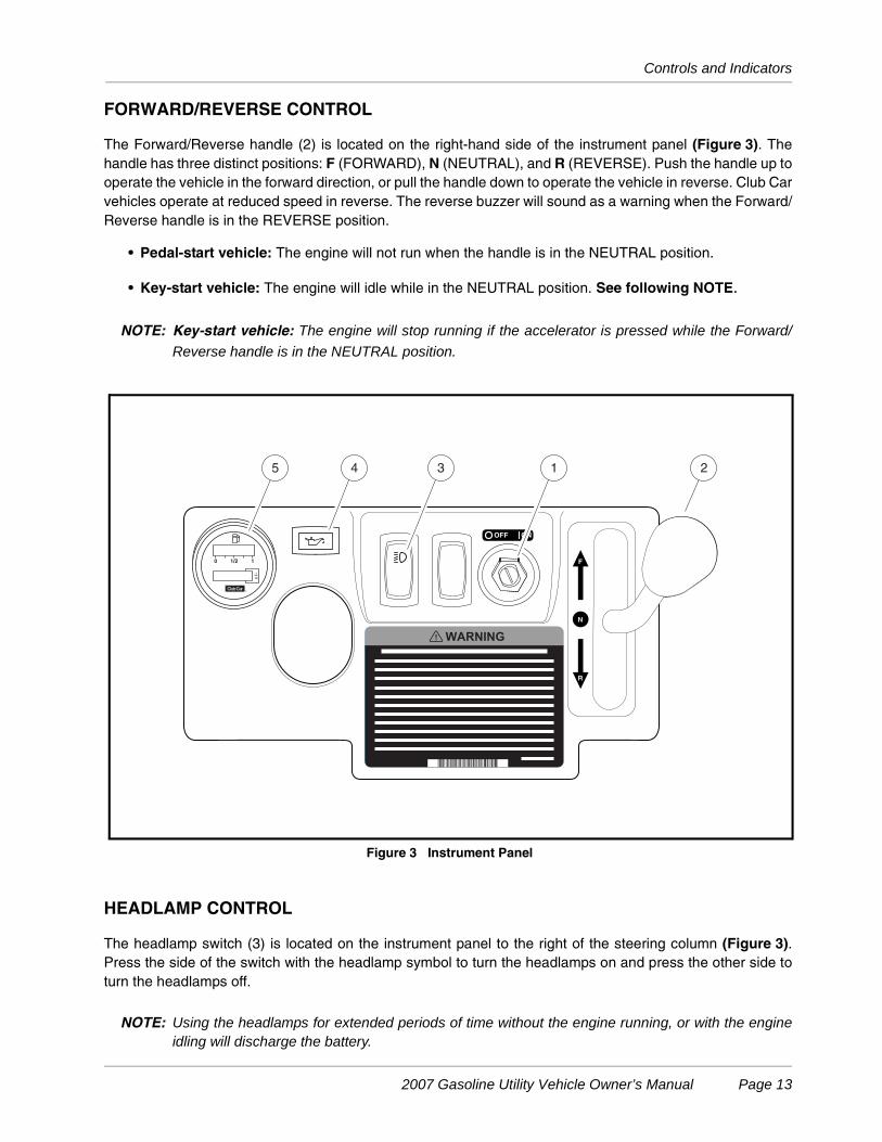
The key switch (1) is mounted on the dash to the right of the steering column (Figure 3).
• Pedal-start vehicle: The key switch has two positions, OFF and ON, which are clearly labeled.
• Key-start vehicle: The key switch has three positions, OFF, ON and START. To start the vehicle, turnthe key past the ON position to the START position and hold until the engine is running smoothly.Release the key and it will return to the ON position and the engine should idle. See following WARN-ING and CAUTION.
ý WARNING
• Moving parts! Keep clear of the engine compartment while the engine is running.
CAUTION
• Do not “rev” the engine for long periods of time while the Forward/Reverse handle is in theNEUTRAL position. Failure to heed this caution could result in damage to the unitizedtransaxle.
• Do not shift the Forward/Reverse handle while the accelerator pedal is pressed. Shift thehandle only when the vehicle is at a complete stop. Failure to heed this caution could result indamage to the unitized transaxle.
NOTE: The key can be removed only when the key switch is in the OFF position.
Page 12 2007 Gasoline Utility Vehicle Owner’s Manual
Controls and Indicators
FORWARD/REVERSE CONTROL
The Forward/Reverse handle (2) is located on the right-hand side of the instrument panel (Figure 3). Thehandle has three distinct positions: F (FORWARD), N (NEUTRAL), and R (REVERSE). Push the handle up tooperate the vehicle in the forward direction, or pull the handle down to operate the vehicle in reverse. Club Carvehicles operate at reduced speed in reverse. The reverse buzzer will sound as a warning when the Forward/Reverse handle is in the REVERSE position.
• Pedal-start vehicle: The engine will not run when the handle is in the NEUTRAL position.
• Key-start vehicle: The engine will idle while in the NEUTRAL position. See following NOTE.
NOTE: Key-start vehicle: The engine will stop running if the accelerator is pressed while the Forward/
Reverse handle is in the NEUTRAL position.
HEADLAMP CONTROL
The headlamp switch (3) is located on the instrument panel to the right of the steering column (Figure 3).Press the side of the switch with the headlamp symbol to turn the headlamps on and press the other side toturn the headlamps off.
NOTE: Using the headlamps for extended periods of time without the engine running, or with the engineidling will discharge the battery.
Figure 3 Instrument Panel
0 1/2 1
1
10
1345 2
2007 Gasoline Utility Vehicle Owner’s Manual Page 13
Controls and Indicators
LOW OIL WARNING LAMP
The vehicle is equipped with a low oil warning lamp (4), located on the instrument panel just above the steer-ing column (Figure 3). If the warning lamp comes on, oil should be checked and added to the engine as nec-essary before continuing to use the vehicle. The vehicle should never be driven when the low oil warning lampremains on. If the warning lamp goes on and off, the vehicle may be driven, but oil should be added at the firstopportunity. If the oil level is correct and the warning lamp stays on, have a trained technician check the vehi-cle.
CAUTION
• Failure to add oil immediately when the low oil warning lamp stays on may result inpermanent engine damage.
FUEL GAUGE/HOUR METER
The vehicle is equipped with a fuel gauge/hour meter (5), located on the instrument panel (Figure 3). The fuelgauge allows the operator to monitor the fuel level in the vehicle. The hour meter should be used by thetrained technician to track vehicle usage and determine when periodic service procedures are required. SeePeriodic Service Schedule on page 26.
ACCELERATOR PEDAL
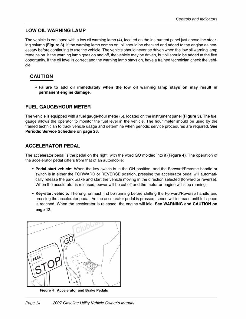
The accelerator pedal is the pedal on the right, with the word GO molded into it (Figure 4). The operation ofthe accelerator pedal differs from that of an automobile:
• Pedal-start vehicle: When the key switch is in the ON position, and the Forward/Reverse handle orswitch is in either the FORWARD or REVERSE position, pressing the accelerator pedal will automati-cally release the park brake and start the vehicle moving in the direction selected (forward or reverse).When the accelerator is released, power will be cut off and the motor or engine will stop running.
• Key-start vehicle: The engine must first be running before shifting the Forward/Reverse handle andpressing the accelerator pedal. As the accelerator pedal is pressed, speed will increase until full speedis reached. When the accelerator is released, the engine will idle. See WARNING and CAUTION onpage 12.
Figure 4 Accelerator and Brake Pedals
Page 14 2007 Gasoline Utility Vehicle Owner’s Manual
Controls and Indicators
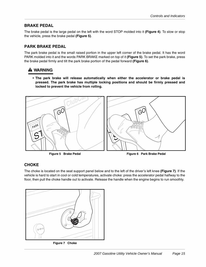
BRAKE PEDALThe brake pedal is the large pedal on the left with the word STOP molded into it (Figure 4). To slow or stopthe vehicle, press the brake pedal (Figure 5).
PARK BRAKE PEDALThe park brake pedal is the small raised portion in the upper left corner of the brake pedal. It has the wordPARK molded into it and the words PARK BRAKE marked on top of it (Figure 5). To set the park brake, pressthe brake pedal firmly and tilt the park brake portion of the pedal forward (Figure 6).
ý WARNING
• The park brake will release automatically when either the accelerator or brake pedal ispressed. The park brake has multiple locking positions and should be firmly pressed andlocked to prevent the vehicle from rolling.
CHOKEThe choke is located on the seat support panel below and to the left of the driver’s left knee (Figure 7). If thevehicle is hard to start in cool or cold temperatures, activate choke: press the accelerator pedal halfway to thefloor, then pull the choke handle out to activate. Release the handle when the engine begins to run smoothly.
Figure 5 Brake Pedal Figure 6 Park Brake Pedal
Figure 7 Choke
2007 Gasoline Utility Vehicle Owner’s Manual Page 15
Pre-Operation and Daily Safety Checklist
NEUTRAL LOCKOUT
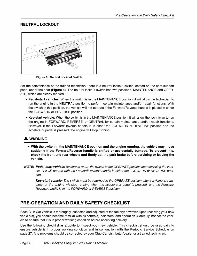
For the convenience of the trained technician, there is a neutral lockout switch located on the seat supportpanel under the seat (Figure 8). The neutral lockout switch has two positions, MAINTENANCE and OPER-ATE, which are clearly marked.
• Pedal-start vehicles: When the switch is in the MAINTENANCE position, it will allow the technician torun the engine in the NEUTRAL position to perform certain maintenance and/or repair functions. Withthe switch in this position, the vehicle will not operate if the Forward/Reverse handle is placed in eitherthe FORWARD or REVERSE position.
• Key-start vehicle: When the switch is in the MAINTENANCE position, it will allow the technician to runthe engine in FORWARD, REVERSE, or NEUTRAL for certain maintenance and/or repair functions.However, if the Forward/Reverse handle is in either the FORWARD or REVERSE position and theaccelerator pedal is pressed, the engine will stop running.
ý WARNING
• With the switch in the MAINTENANCE position and the engine running, the vehicle may movesuddenly if the Forward/Reverse handle is shifted or accidentally bumped. To prevent this,chock the front and rear wheels and firmly set the park brake before servicing or leaving thevehicle.
NOTE: Pedal-start vehicle: Be sure to return the switch to the OPERATE position after servicing the vehi-cle, or it will not run with the Forward/Reverse handle in either the FORWARD or REVERSE posi-tion.
Key-start vehicle: The switch must be returned to the OPERATE position after servicing is com-plete, or the engine will stop running when the accelerator pedal is pressed, and the Forward/Reverse handle is in the FORWARD or REVERSE position.
PRE-OPERATION AND DAILY SAFETY CHECKLIST
Each Club Car vehicle is thoroughly inspected and adjusted at the factory; however, upon receiving your newvehicle(s), you should become familiar with its controls, indicators, and operation. Carefully inspect the vehi-cle to ensure that it is in proper working condition before accepting delivery.
Use the following checklist as a guide to inspect your new vehicle. This checklist should be used daily toensure vehicle is in proper working condition and in conjunction with the Periodic Service Schedule onpage 27. Any problems should be corrected by your Club Car distributor/dealer or a trained technician.
Figure 8 Neutral Lockout Switch
Page 16 2007 Gasoline Utility Vehicle Owner’s Manual
Performance Inspection
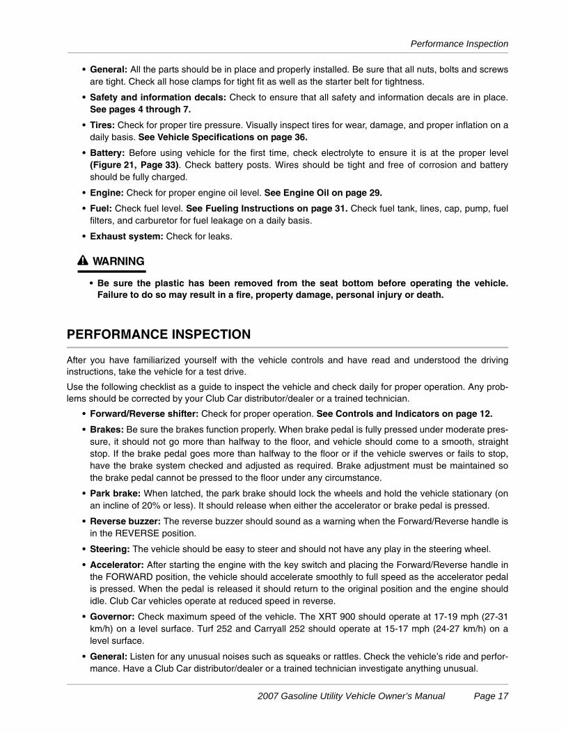
• General: All the parts should be in place and properly installed. Be sure that all nuts, bolts and screwsare tight. Check all hose clamps for tight fit as well as the starter belt for tightness.
• Safety and information decals: Check to ensure that all safety and information decals are in place.See pages 4 through 7.
• Tires: Check for proper tire pressure. Visually inspect tires for wear, damage, and proper inflation on adaily basis. See Vehicle Specifications on page 36.
• Battery: Before using vehicle for the first time, check electrolyte to ensure it is at the proper level(Figure 21, Page 33). Check battery posts. Wires should be tight and free of corrosion and batteryshould be fully charged.
• Engine: Check for proper engine oil level. See Engine Oil on page 29.
• Fuel: Check fuel level. See Fueling Instructions on page 31. Check fuel tank, lines, cap, pump, fuelfilters, and carburetor for fuel leakage on a daily basis.
• Exhaust system: Check for leaks.
ý WARNING
• Be sure the plastic has been removed from the seat bottom before operating the vehicle.Failure to do so may result in a fire, property damage, personal injury or death.
PERFORMANCE INSPECTION
After you have familiarized yourself with the vehicle controls and have read and understood the drivinginstructions, take the vehicle for a test drive.
Use the following checklist as a guide to inspect the vehicle and check daily for proper operation. Any prob-lems should be corrected by your Club Car distributor/dealer or a trained technician.
• Forward/Reverse shifter: Check for proper operation. See Controls and Indicators on page 12.
• Brakes: Be sure the brakes function properly. When brake pedal is fully pressed under moderate pres-sure, it should not go more than halfway to the floor, and vehicle should come to a smooth, straightstop. If the brake pedal goes more than halfway to the floor or if the vehicle swerves or fails to stop,have the brake system checked and adjusted as required. Brake adjustment must be maintained sothe brake pedal cannot be pressed to the floor under any circumstance.
• Park brake: When latched, the park brake should lock the wheels and hold the vehicle stationary (onan incline of 20% or less). It should release when either the accelerator or brake pedal is pressed.
• Reverse buzzer: The reverse buzzer should sound as a warning when the Forward/Reverse handle isin the REVERSE position.
• Steering: The vehicle should be easy to steer and should not have any play in the steering wheel.
• Accelerator: After starting the engine with the key switch and placing the Forward/Reverse handle inthe FORWARD position, the vehicle should accelerate smoothly to full speed as the accelerator pedalis pressed. When the pedal is released it should return to the original position and the engine shouldidle. Club Car vehicles operate at reduced speed in reverse.
• Governor: Check maximum speed of the vehicle. The XRT 900 should operate at 17-19 mph (27-31km/h) on a level surface. Turf 252 and Carryall 252 should operate at 15-17 mph (24-27 km/h) on alevel surface.
• General: Listen for any unusual noises such as squeaks or rattles. Check the vehicle’s ride and perfor-mance. Have a Club Car distributor/dealer or a trained technician investigate anything unusual.
2007 Gasoline Utility Vehicle Owner’s Manual Page 17
Driving Instructions
DRIVING INSTRUCTIONS
ý WARNING
• Only licensed drivers should be allowed to drive the vehicle.• Before allowing anyone to drive the vehicle, make sure the driver is familiar with all controls
and operating procedures.• No one under the age of 16 years should be allowed to drive the vehicle.• No more than two people should be on the vehicle at one time.• Do not allow riders in the cargo bed.• For night use, the vehicle must be equipped with headlights, taillights, and reflectors.• The vehicle is not specially equipped for handicapped persons:
- Be sure all persons can properly operate the vehicle prior to allowing them to drive thevehicle.
- Be sure all passengers are capable of securing themselves in a vehicle before allowingthem to ride in one.
• Stop the vehicle before shifting the Forward/Reverse handle. Engine must be at idle beforeshifting Forward/Reverse handle. Failure to do so may result in injury to inattentivepassengers and (or) damage to the vehicle.
• To help avoid being struck, do not stand in front of or behind the vehicle.• Do not leave children unattended on vehicle.• Operate the vehicle from the driver seat only.• To help prevent falls from the vehicle, remain seated and hold on to seat handles at all times.
Driver should keep both hands on the steering wheel when the vehicle is in motion.• To help prevent the possibility of serious injury, keep entire body inside the vehicle.• To help prevent overturning the vehicle, drive slowly in turns.• To help prevent overturning the vehicle, drive slowly straight up and down slopes. Avoid
driving the vehicle on slopes exceeding 20% incline.• Avoid stopping a loaded vehicle on a hill. If a loaded vehicle must be stopped on a hill, avoid
sudden starts or rolling backwards and stopping suddenly. Failure to heed this warning couldresult in overturning the vehicle.
• To help avoid possible injury to inattentive passengers and (or) damage to the vehicle, avoidsudden starts, sudden stops, and abrupt turns.
• To help avoid the possibility of losing control of or overturning the vehicle, reduce speed foradverse driving conditions such as wet grass or rough terrain.
• Do not use the vehicle on public roads. It is neither designed nor intended for street use andshould not be licensed for use on public roads.
• The vehicle should be driven in only specified areas by trained drivers.• Do not drive while under the influence of alcohol, drugs, or medications.• Use brakes to reduce speed when coasting downhill.• Never attempt jumps.
No one should drive the vehicle without first being instructed in the proper operation and use of vehicle con-trols. An experienced operator should accompany each first-time driver on a test drive before allowing thedriver to operate the vehicle alone.
To ensure safe operation of the vehicle, follow exactly and in order, all of the following procedures. Read andunderstand all instructions prior to driving the vehicle.
Page 18 2007 Gasoline Utility Vehicle Owner’s Manual
Driving Instructions
STARTING THE VEHICLE
1. Make sure load is secure.
2. Make sure everyone is seated and holding onto hand holds or handrails. Driver should have both handson the steering wheel.
3. Make sure wheels are turned in desired direction and that nothing is obstructing vehicle’s path.
4. Start the vehicle:
Pedal-start vehicles:
4.1. Turn the key to the ON position.
4.2. Select direction by placing the Forward/Reverse handle or switch in the desired position (F = for-ward or R = reverse). A buzzer will sound as a warning when the Forward/Reverse handle or switchis in the REVERSE position.
4.3. Slowly press the accelerator pedal. The park brake will release automatically and the vehicle willstart to move. As the accelerator pedal is pressed, speed will increase until full speed is reached.See following WARNING and NOTE.
Key-start vehicles:
4.4. Make sure the Forward/Reverse handle is in the NEUTRAL position.
4.5. Press and hold brake pedal.
4.6. Turn the key all the way to the START position and release after the engine has started. The enginewill idle with the Forward/Reverse handle in the NEUTRAL position.
4.7. Keeping brake engaged, place the Forward/Reverse handle in desired position (F = forward or R =reverse). A buzzer will sound as a warning when the vehicle is in the REVERSE position.
4.8. Release brake pedal and slowly press accelerator pedal. The park brake will release automaticallyand the vehicle will start to move. As the accelerator pedal is pressed, speed will increase until fullspeed is reached. See following WARNING and NOTE.
ý WARNING
• Operator must control vehicle speed when going downhill.
• Do not shift the vehicle out of FORWARD while going downhill. If you do you will not be ableto shift into REVERSE or back into FORWARD until stopped.
• Press the brake pedal as necessary and partially press the accelerator when descending ahill. With the accelerator pedal partially pressed, the governor will cause the engine to assistthe brakes in controlling downhill speed.
NOTE: Pedal-start vehicle: If the Forward/Reverse handle or switch is shifted into the NEUTRAL posi-tion, power will be cut off and the engine will stop running.
Key-start vehicle: If accelerator pedal is pressed while the Forward/Reverse handle is in theNEUTRAL position, or if Forward/Reverse handle is shifted from the FORWARD to REVERSEposition while the accelerator pedal is pressed, power will be cut off and the engine will stop run-ning. To keep engine running, the accelerator pedal must be released completely before shiftingthe vehicle.
2007 Gasoline Utility Vehicle Owner’s Manual Page 19
Bed Latch
STOPPING THE VEHICLE
ý WARNING
• Driving through water may affect the brakes. After driving through water, check effectivenessof the brakes by gently pressing the brake pedal. If the vehicle does not slow down at thenormal rate, continue to press the brake pedal until the brakes dry out and normalperformance returns.
ý CAUTION
• When stopped on a hill, use the brake pedal to hold your position. Do not use the acceleratorpedal.
To stop the vehicle, release the accelerator pedal and press the brake pedal until the vehicle comes to a com-plete stop.
PARKING AND LEAVING THE VEHICLE
1. After stopping the vehicle, firmly press park brake pedal until it locks. This will prevent the vehicle fromrolling.
2. Turn the key switch to the OFF position and place the Forward/Reverse handle in the NEUTRAL position.Remove the key and turn the fuel shut-off valve to the closed (OFF) position when the vehicle is not inuse (Figure 11). See also Figure 19, Page 32.
BED LATCH
See General Warnings on page 10.
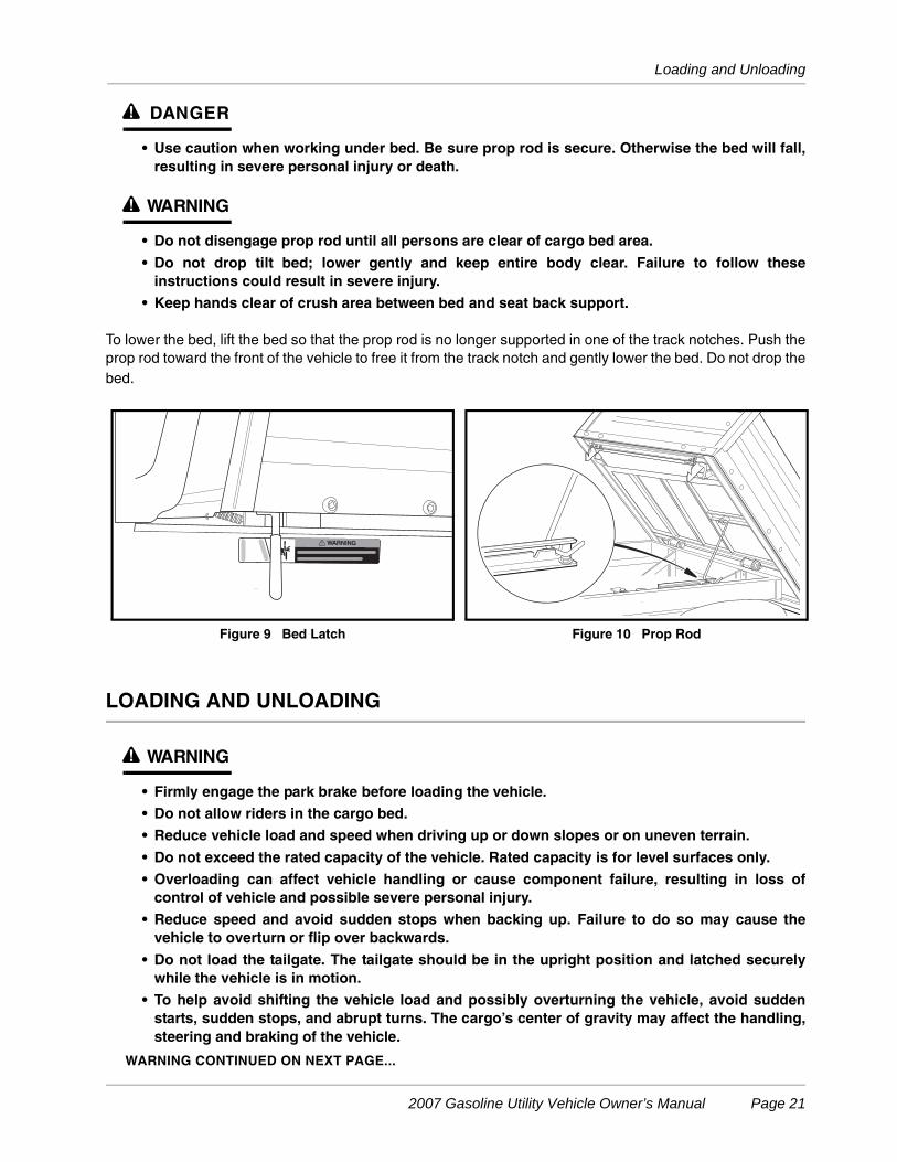
The vehicle is equipped with a bed latch on the driver side of the vehicle (Figure 9) and an automaticallyengaging prop rod (Figure 10). To lift the bed, pull the latch handle toward the rear of the vehicle and lift thebed. To close the bed, disengage the prop rod and gently lower the bed until the bed latch engages. DO NOTdrop the bed. See following WARNING and NOTE.
ý WARNING
• Keep hands clear of crush area between bed and seat back support.
NOTE: The vehicle is equipped with an automatically engaging prop rod (Figure 10), unless equippedwith the hydraulic or electric bed lift accessory.
PROP ROD
See General Warnings on page 10.
The vehicle is equipped with an automatically engaging prop rod and prop rod track on the driver side of therear body (Figure 10). When pulling the bed latch handle and lifting the bed, the prop rod will come to rest inone of the notches in the prop rod track. See following DANGER and WARNING.
Page 20 2007 Gasoline Utility Vehicle Owner’s Manual
Loading and Unloading
ý DANGER
• Use caution when working under bed. Be sure prop rod is secure. Otherwise the bed will fall,resulting in severe personal injury or death.
ý WARNING
• Do not disengage prop rod until all persons are clear of cargo bed area.
• Do not drop tilt bed; lower gently and keep entire body clear. Failure to follow theseinstructions could result in severe injury.
• Keep hands clear of crush area between bed and seat back support.
To lower the bed, lift the bed so that the prop rod is no longer supported in one of the track notches. Push theprop rod toward the front of the vehicle to free it from the track notch and gently lower the bed. Do not drop thebed.
LOADING AND UNLOADING
ý WARNING
• Firmly engage the park brake before loading the vehicle.
• Do not allow riders in the cargo bed.
• Reduce vehicle load and speed when driving up or down slopes or on uneven terrain.
• Do not exceed the rated capacity of the vehicle. Rated capacity is for level surfaces only.
• Overloading can affect vehicle handling or cause component failure, resulting in loss ofcontrol of vehicle and possible severe personal injury.
• Reduce speed and avoid sudden stops when backing up. Failure to do so may cause thevehicle to overturn or flip over backwards.
• Do not load the tailgate. The tailgate should be in the upright position and latched securelywhile the vehicle is in motion.
• To help avoid shifting the vehicle load and possibly overturning the vehicle, avoid suddenstarts, sudden stops, and abrupt turns. The cargo’s center of gravity may affect the handling,steering and braking of the vehicle.
WARNING CONTINUED ON NEXT PAGE...
Figure 9 Bed Latch Figure 10 Prop Rod
2007 Gasoline Utility Vehicle Owner’s Manual Page 21
Towing with the Vehicle
ý WARNING
• To help prevent cargo from shifting and possibly injuring a passenger or affecting thevehicle’s handling, make sure cargo is well secured.
• Avoid top-heavy loads. The center of gravity of a load should never exceed 15 inches (38 cm)above the bottom of the cargo bed.
• Unload cargo bed before raising vehicle with a lift, hoist, or jack.
• The cargo’s center of gravity may affect the handling, steering and braking of the vehicle.When the vehicle is loaded, reduce speed and drive slowly in turns.
• Avoid stopping on a hill when loaded. If you must stop on a hill, avoid sudden starts, or rollingbackwards and stopping suddenly. Failure to heed this warning may cause vehicle tooverturn, possibly resulting in severe personal injury.
Center and secure cargo as far forward as possible in the cargo bed. Do not overload the vehicle. See the fol-lowing chart for vehicle capacities.
Maximum payload capacity must be reduced accordingly when any option or accessory is installed on thevehicle. See following NOTE.
NOTE: A standard vehicle with a cab accessory weighing 235 lb. (107 kg) must reduce its maximum pay-load capacity by 235 lb. (107 kg) to 465 lb. (119 kg).
TOWING WITH THE VEHICLE
ý WARNING
• Do not tow a vehicle or trailer on public streets or highways.
• Normal vehicle operating speed should be reduced when towing.
• Extreme caution should be used when towing.
• Do not allow riders in the vehicle or trailer being towed.
• Total vehicle capacity, including the vehicle load rating and the gross weight of the vehicle ortrailer being towed, should not exceed the weight previously specified.
• Avoid sudden starts, sudden stops, and tight turns when towing.
• Avoid stopping on a hill when towing. If you must stop on a hill, avoid sudden starts, or rollingbackwards and stopping suddenly. Failure to heed this warning could cause vehicle tooverturn, possibly resulting in severe personal injury.
Because towing another Club Car vehicle or a trailer can have adverse effects on vehicle handling, be espe-cially cautious when towing with a Club Car vehicle. See the preceding chart for vehicle capacities.
ALL VEHICLES
Maximum payload capacity(Cargo bed load plus gross trailer weight)
500 lb.(227 kg)
Maximum vehicle capacity (Cargo bed load, passengers, plus gross trailer weight)
900 lb.(408 kg)
Trailer tongue weight 150 lb. force(667 N)
Page 22 2007 Gasoline Utility Vehicle Owner’s Manual
Transporting on a Trailer
Parking the vehicle with a trailer on a hill should be avoided. If you must park on a hill, apply the park brakeand have someone chock the tires of the trailer. Slowly release the park brake to allow the chocks to absorbthe load of the trailer, then firmly set the park brake.
Total vehicle capacity, including tow vehicle load and gross trailer weight, must not exceed 900 lb. (409 kg).
TRANSPORTING ON A TRAILER
ý WARNING
• Turn the fuel shut-off valve to the closed (OFF) position (Figure 11, Page 24).
• Do not allow riders in the trailer being towed.
• Avoid sudden starts, sudden stops, and tight turns when towing.
• Avoid stopping on a hill when towing. If you must stop on a hill, avoid sudden starts, or rollingbackwards and stopping suddenly. Failure to heed this warning could cause the vehicle tooverturn, possibly resulting in severe personal injury.
• Reduce normal driving speed when transporting a vehicle or trailer.
• For use on public roads, the trailer must meet all federal, state, and local requirements suchas taillights, brake lights, etc.
• Do not tow a Club Car vehicle behind a passenger vehicle or truck on a public road unless it ison an approved trailer.
• The vehicle to be transported should be tied securely to the trailer, with the Forward/Reversehandle in the NEUTRAL position, the key switch in the OFF position, and the park brake firmlyengaged.
• Because of the added length of the trailer, use caution when making turns.
• Do not transport the vehicle on a trailer with a load in the vehicle cargo bed.
• Remove the vehicle windshield and the seat bottom before transporting on a trailer.
If the vehicle must be transported over long distances or on public highways, it should be transported on anapproved trailer that has an approved trailer that has a load rating of at least 2000 lb. (909 kg) per vehiclebeing transported.
NOTE: A two-car trailer should be rated at 2 x 2000 lb. = 4000 lb. (2 x 909 = 1818 kg).
STORAGE
See General Warnings on page 10.
ý DANGER
• Do not attempt to drain gasoline when the engine is hot or while it is running.
• Be sure to clean up any spilled gasoline before operating the vehicle.
• Store gasoline in an approved gasoline container only. Store in a well-ventilated area awayfrom sparks, open flames, heaters or heat sources.
• Keep gasoline out of the reach of children.
• Do not siphon gasoline from the vehicle.
2007 Gasoline Utility Vehicle Owner’s Manual Page 23
Storage
ý WARNING
• Turn the key switch to the OFF position, remove the key and leave the Forward/Reversehandle in the NEUTRAL position during storage. This is to prevent unintentionally starting thevehicle or a fire hazard.
• Turn the fuel shut-off valve to the closed (OFF) position (Figure 11, Page 24).
• Do not attempt to charge frozen batteries or batteries with bulged cases. Discard the battery.Frozen batteries can explode.
ý CAUTION
• Batteries in a low state of charge will freeze at low temperatures.
PREPARING THE VEHICLE FOR EXTENDED STORAGE
1. Unload the vehicle so that tires are supporting only the weight of the vehicle.
2. Store vehicle in a cool, dry place. This will minimize battery self-discharge. If the battery appears to beweak, have it charged by a trained technician. Use an automotive-type 12-volt battery charger rated at10 amps or less.
3. Drain carburetor and seal the fuel tank.
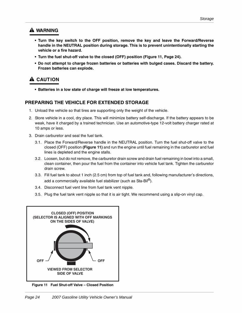
3.1. Place the Forward/Reverse handle in the NEUTRAL position. Turn the fuel shut-off valve to theclosed (OFF) position (Figure 11) and run the engine until fuel remaining in the carburetor and fuellines is depleted and the engine stalls.
3.2. Loosen, but do not remove, the carburetor drain screw and drain fuel remaining in bowl into a small,clean container, then pour the fuel from the container into vehicle fuel tank. Tighten the carburetordrain screw.
3.3. Fill fuel tank to about 1 inch (2.5 cm) from top of fuel tank and, following manufacturer’s directions,
add a commercially available fuel stabilizer (such as Sta-Bil®).
3.4. Disconnect fuel vent line from fuel tank vent nipple.
3.5. Plug the fuel tank vent nipple so that it is air tight. We recommend using a slip-on vinyl cap.
Figure 11 Fuel Shut-off Valve – Closed Position
CLOSED (OFF) POSITION(SELECTOR IS ALIGNED WITH OFF MARKINGS
ON THE SIDES OF VALVE)
OFFOFF
VIEWED FROM SELECTOR SIDE OF VALVE
Page 24 2007 Gasoline Utility Vehicle Owner’s Manual
Storage
4. Disconnect battery cables, negative (–) cable first.
5. Batteries should be clean and free of corrosion. Wash tops and terminals of batteries with a solution ofbaking soda and water (1 cup (237mL) baking soda per 1 gallon (3.8 L) of water). Rinse solution off bat-teries. Do not allow this solution to enter the batteries. Be sure terminals are tight. Let the terminals dryand then coat them with Battery Terminal Protector Spray (CCI P/N 1014305).
6. To protect the engine, remove the spark plug and pour 1/2 ounce (14.2 mL) of SAE 10 weight oil intoengine through the spark plug hole. Rotate engine crankshaft by hand several times and then installspark plug.
7. Adjust tires to recommended tire pressure. See Vehicle Specifications on page 36.
8. Perform semiannual periodic lubrication. See Periodic Lubrication Schedule on page 28.
9. Thoroughly clean front body, rear body, seats, cargo bed, engine compartment, and underside of vehicle.
10. Do not engage the park brake. Chock the wheels to prevent the vehicle from rolling.
RETURNING THE STORED VEHICLE TO SERVICE
1. Restore fuel system to operation (Figure 19, Page 32).
1.1. Remove plug from the fuel tank vent.
1.2. Connect vent tube to fuel tank vent.
2. Connect battery cables, positive (+) cable first, and tighten terminals to 12 ft-lb (16 N·m).
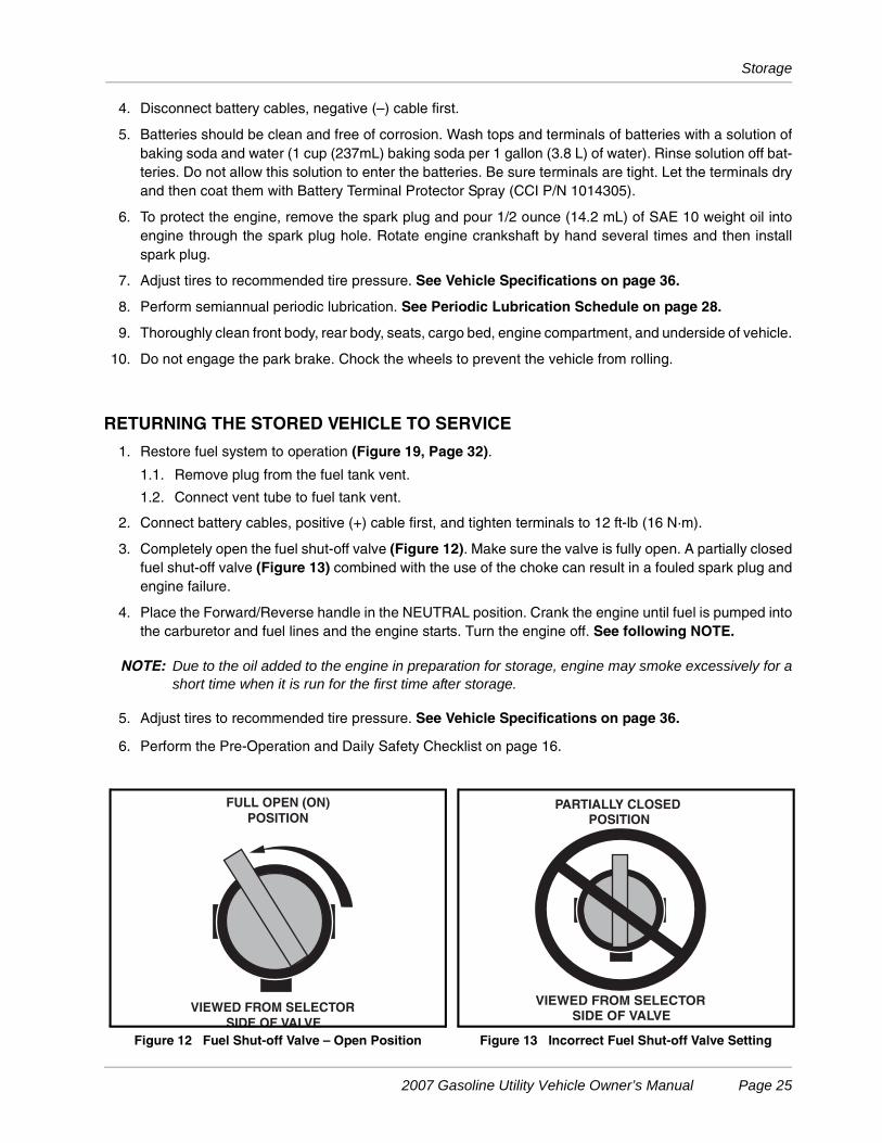
3. Completely open the fuel shut-off valve (Figure 12). Make sure the valve is fully open. A partially closedfuel shut-off valve (Figure 13) combined with the use of the choke can result in a fouled spark plug andengine failure.
4. Place the Forward/Reverse handle in the NEUTRAL position. Crank the engine until fuel is pumped intothe carburetor and fuel lines and the engine starts. Turn the engine off. See following NOTE.
NOTE: Due to the oil added to the engine in preparation for storage, engine may smoke excessively for ashort time when it is run for the first time after storage.
5. Adjust tires to recommended tire pressure. See Vehicle Specifications on page 36.
6. Perform the Pre-Operation and Daily Safety Checklist on page 16.
Figure 12 Fuel Shut-off Valve – Open Position Figure 13 Incorrect Fuel Shut-off Valve Setting
VIEWED FROM SELECTOR
SIDE OF VALVE
FULL OPEN (ON)
POSITION
VIEWED FROM SELECTOR SIDE OF VALVE
PARTIALLY CLOSEDPOSITION
2007 Gasoline Utility Vehicle Owner’s Manual Page 25
Maintenance
MAINTENANCE
See General Warnings on page 10.
To ensure trouble-free vehicle performance, it is very important to follow an established preventive mainte-nance program. Regular and consistent vehicle maintenance can prevent vehicle downtime and expensiverepairs that result from neglect. Use the Pre-Operation and Daily Safety Checklist on page 16 and the follow-ing Periodic Service Schedule and Periodic Lubrication Schedule to keep the vehicle in proper working con-dition.
Any vehicle not functioning correctly should be removed from use until it is properly repaired. This will preventfurther damage to the vehicle and avoid the possibility of injury due to unsafe conditions.
Contact your local Club Car distributor/dealer to perform all repairs and semi-annual and annual periodic ser-vice. See following WARNING.
ý WARNING
• If any problems are found during scheduled inspection or service, do not operate the vehicleuntil repairs are made. Failure to make necessary repairs could result in fire, propertydamage, severe personal injury, or death.
• Do not wear loose clothing or jewelry, such as rings, watches, chains, etc., when servicing thevehicle.
• Turn the key switch to the OFF position, remove the key, place the Forward/Reverse handle inthe NEUTRAL position, and chock the wheels prior to servicing.
• Moving parts: Do not attempt to service vehicle while the engine is running.
• Do not work on vehicle powertrain or under the cargo bed when it is loaded.
• Turn the fuel shut-off valve to the closed (OFF) position (Figure 11, Page 24).
• Hot! Do not attempt to service hot engine or exhaust system. Failure to heed this warningcould result in severe burns.
• Do not remove prop rod or close bed until all persons are clear of the bed area. Lower the bedgently, keeping entire body clear. Do not drop the bed. Failure to follow these instructionscould result in severe personal injury.
• A hydraulic bed lift system is under pressure. Wear a face shield and use extreme cautionwhen servicing it.
PERIODIC SERVICE SCHEDULE
See General Warnings on page 10.
ý WARNING
• Service, repairs, and adjustments must be made per instructions in the appropriatemaintenance and service manual.
NOTE: If the vehicle is constantly subjected to heavy use or severe operating conditions, the preventivemaintenance procedures should be performed more often than recommended in the periodic ser-vice and lubrication schedules.
Both the Periodic Service Schedule and the Periodic Lubrication Schedule must be followed tokeep vehicle in optimum operating condition.
Page 26 2007 Gasoline Utility Vehicle Owner’s Manual
Periodic Service Schedule
ý WARNING
• If any problems are found during scheduled inspection or service, do not operate the vehicleuntil repairs are made. Failure to make necessary repairs could result in fire, propertydamage, severe personal injury, or death.
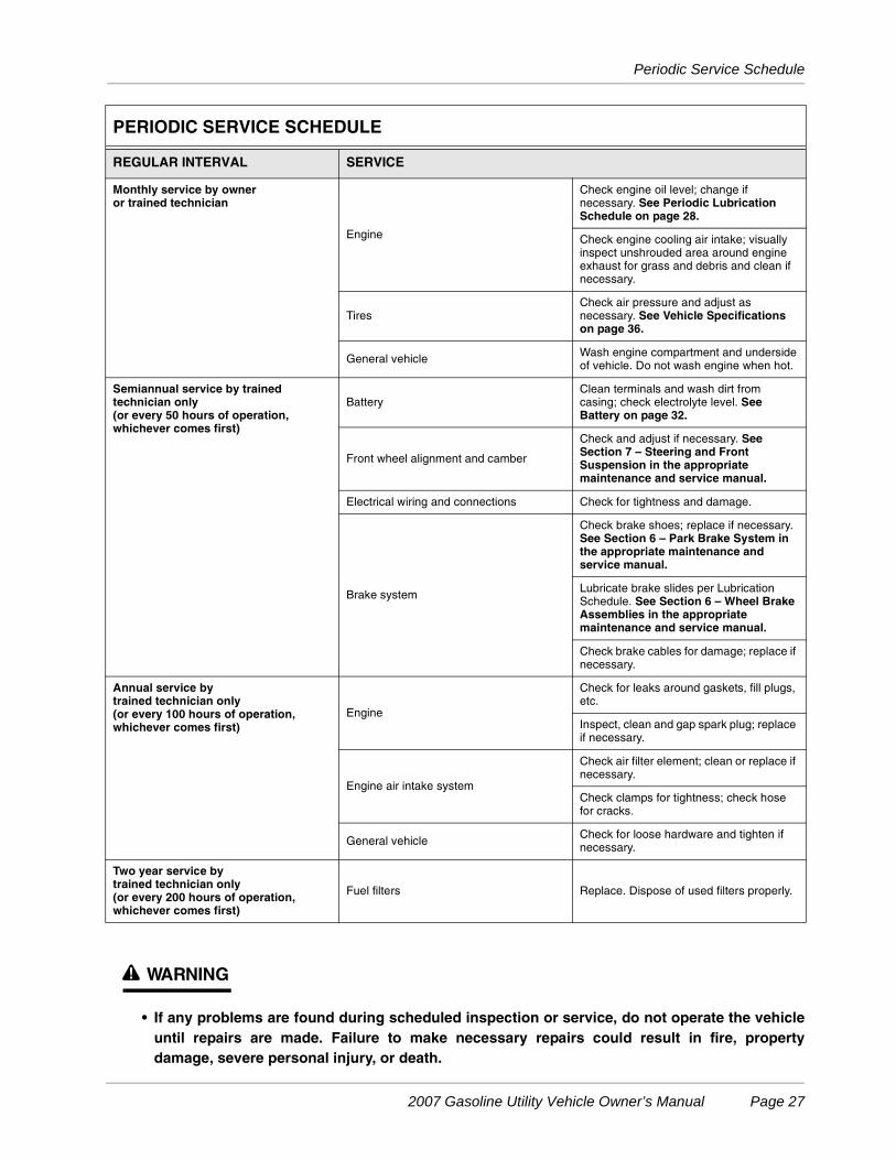
PERIODIC SERVICE SCHEDULE
REGULAR INTERVAL SERVICE
Monthly service by owneror trained technician
Engine
Check engine oil level; change if necessary. See Periodic Lubrication Schedule on page 28.
Check engine cooling air intake; visually inspect unshrouded area around engine exhaust for grass and debris and clean if necessary.
TiresCheck air pressure and adjust as necessary. See Vehicle Specifications on page 36.
General vehicle Wash engine compartment and undersideof vehicle. Do not wash engine when hot.
Semiannual service by trained technician only(or every 50 hours of operation, whichever comes first)
BatteryClean terminals and wash dirt from casing; check electrolyte level. See Battery on page 32.
Front wheel alignment and camber
Check and adjust if necessary. See Section 7 – Steering and Front Suspension in the appropriate maintenance and service manual.
Electrical wiring and connections Check for tightness and damage.
Brake system
Check brake shoes; replace if necessary.See Section 6 – Park Brake System in the appropriate maintenance and service manual.
Lubricate brake slides per Lubrication Schedule. See Section 6 – Wheel Brake Assemblies in the appropriate maintenance and service manual.
Check brake cables for damage; replace if necessary.
Annual service bytrained technician only(or every 100 hours of operation, whichever comes first)
Engine
Check for leaks around gaskets, fill plugs, etc.
Inspect, clean and gap spark plug; replace if necessary.
Engine air intake system
Check air filter element; clean or replace if necessary.
Check clamps for tightness; check hose for cracks.
General vehicle Check for loose hardware and tighten if necessary.
Two year service by trained technician only(or every 200 hours of operation, whichever comes first)
Fuel filters Replace. Dispose of used filters properly.
2007 Gasoline Utility Vehicle Owner’s Manual Page 27
Periodic Lubrication Schedule
PERIODIC LUBRICATION SCHEDULE
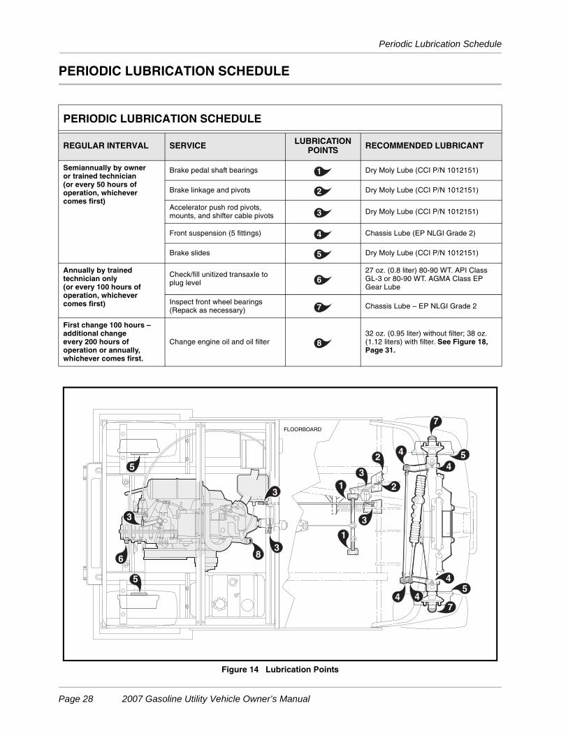
PERIODIC LUBRICATION SCHEDULE
REGULAR INTERVAL SERVICE LUBRICATION POINTS RECOMMENDED LUBRICANT
Semiannually by owneror trained technician (or every 50 hours of operation, whichever comes first)
Brake pedal shaft bearings Dry Moly Lube (CCI P/N 1012151)
Brake linkage and pivots Dry Moly Lube (CCI P/N 1012151)
Accelerator push rod pivots, mounts, and shifter cable pivots Dry Moly Lube (CCI P/N 1012151)
Front suspension (5 fittings) Chassis Lube (EP NLGI Grade 2)
Brake slides Dry Moly Lube (CCI P/N 1012151)
Annually by trainedtechnician only (or every 100 hours of operation, whichever comes first)
Check/fill unitized transaxle to plug level
27 oz. (0.8 liter) 80-90 WT. API Class GL-3 or 80-90 WT. AGMA Class EP Gear Lube
Inspect front wheel bearings(Repack as necessary) Chassis Lube – EP NLGI Grade 2
First change 100 hours –additional change every 200 hours of operation or annually, whichever comes first.
Change engine oil and oil filter32 oz. (0.95 liter) without filter; 38 oz. (1.12 liters) with filter. See Figure 18, Page 31.
Figure 14 Lubrication Points
1
2
3
4
5
6
7
8
4
4
4
2
2
1
1
7
74
3
83
6
3
FLOORBOARD
4
3
5
53
5
5
Page 28 2007 Gasoline Utility Vehicle Owner’s Manual
Engine Oil
ENGINE OIL
Even though the low oil warning light on the dash should illuminate if oil level becomes low, engine oil levelshould be checked monthly. Vehicle should be on a level surface when checking oil. Do not overfill with oil.
ENGINE OIL AND FILTER CHANGE
Engine oil and oil filter should be changed after the first 100 hours of operation. After that, they should bechanged every 200 hours of operation or annually, whichever comes first.
1. Turn the key switch to the OFF position, then remove the key. Place the Forward/Reverse handle in theneutral POSITION. Chock the front wheels.
2. Access the engine compartment.
3. Disconnect the battery cables, negative (–) cable first. See WARNING “To avoid unintentionally start-ing...” on page 10.
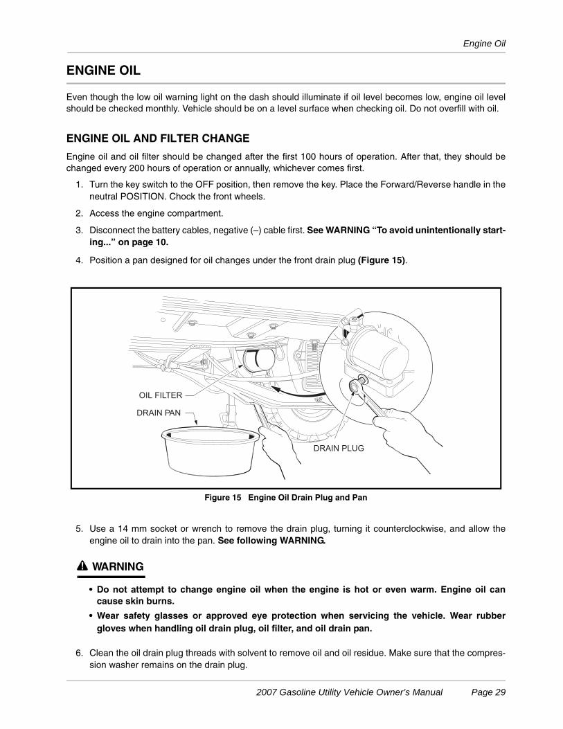
4. Position a pan designed for oil changes under the front drain plug (Figure 15).
5. Use a 14 mm socket or wrench to remove the drain plug, turning it counterclockwise, and allow theengine oil to drain into the pan. See following WARNING.
ý WARNING
• Do not attempt to change engine oil when the engine is hot or even warm. Engine oil cancause skin burns.
• Wear safety glasses or approved eye protection when servicing the vehicle. Wear rubbergloves when handling oil drain plug, oil filter, and oil drain pan.
6. Clean the oil drain plug threads with solvent to remove oil and oil residue. Make sure that the compres-sion washer remains on the drain plug.
Figure 15 Engine Oil Drain Plug and Pan
OIL FILTER
DRAIN PAN
DRAIN PLUG
2007 Gasoline Utility Vehicle Owner’s Manual Page 29
Engine Oil
7. Use a 14 mm socket or wrench and replace the front oil drain plug, turning it clockwise, and tighten to
18 ft-lb (24.4 N·m).
8. Relocate the oil drain pan to a position under the engine oil filter (Figure 15).
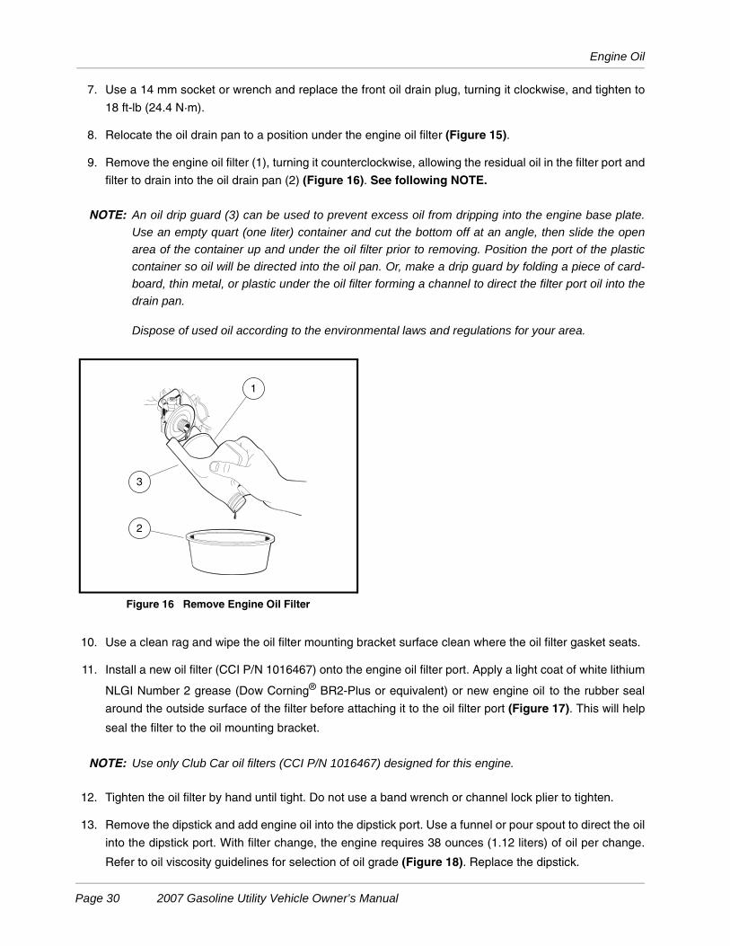
9. Remove the engine oil filter (1), turning it counterclockwise, allowing the residual oil in the filter port and
filter to drain into the oil drain pan (2) (Figure 16). See following NOTE.
NOTE: An oil drip guard (3) can be used to prevent excess oil from dripping into the engine base plate.
Use an empty quart (one liter) container and cut the bottom off at an angle, then slide the open
area of the container up and under the oil filter prior to removing. Position the port of the plastic
container so oil will be directed into the oil pan. Or, make a drip guard by folding a piece of card-
board, thin metal, or plastic under the oil filter forming a channel to direct the filter port oil into the
drain pan.
Dispose of used oil according to the environmental laws and regulations for your area.
10. Use a clean rag and wipe the oil filter mounting bracket surface clean where the oil filter gasket seats.
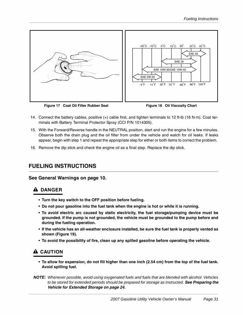
11. Install a new oil filter (CCI P/N 1016467) onto the engine oil filter port. Apply a light coat of white lithium
NLGI Number 2 grease (Dow Corning® BR2-Plus or equivalent) or new engine oil to the rubber seal
around the outside surface of the filter before attaching it to the oil filter port (Figure 17). This will help
seal the filter to the oil mounting bracket.
NOTE: Use only Club Car oil filters (CCI P/N 1016467) designed for this engine.
12. Tighten the oil filter by hand until tight. Do not use a band wrench or channel lock plier to tighten.
13. Remove the dipstick and add engine oil into the dipstick port. Use a funnel or pour spout to direct the oil
into the dipstick port. With filter change, the engine requires 38 ounces (1.12 liters) of oil per change.
Refer to oil viscosity guidelines for selection of oil grade (Figure 18). Replace the dipstick.
Figure 16 Remove Engine Oil Filter
1
2
3
Page 30 2007 Gasoline Utility Vehicle Owner’s Manual
Fueling Instructions
14. Connect the battery cables, positive (+) cable first, and tighten terminals to 12 ft-lb (16 N·m). Coat ter-minals with Battery Terminal Protector Spray (CCI P/N 1014305).
15. With the Forward/Reverse handle in the NEUTRAL position, start and run the engine for a few minutes.Observe both the drain plug and the oil filter from under the vehicle and watch for oil leaks. If leaksappear, begin with step 1 and repeat the appropriate step for either or both items to correct the problem.
16. Remove the dip stick and check the engine oil as a final step. Replace the dip stick.
FUELING INSTRUCTIONS
See General Warnings on page 10.
ý DANGER
• Turn the key switch to the OFF position before fueling.
• Do not pour gasoline into the fuel tank when the engine is hot or while it is running.
• To avoid electric arc caused by static electricity, the fuel storage/pumping device must begrounded. If the pump is not grounded, the vehicle must be grounded to the pump before andduring the fueling operation.
• If the vehicle has an all-weather enclosure installed, be sure the fuel tank is properly vented asshown (Figure 19).
• To avoid the possibility of fire, clean up any spilled gasoline before operating the vehicle.
ý CAUTION
• To allow for expansion, do not fill higher than one inch (2.54 cm) from the top of the fuel tank.Avoid spilling fuel.
NOTE: Whenever possible, avoid using oxygenated fuels and fuels that are blended with alcohol. Vehiclesto be stored for extended periods should be prepared for storage as instructed. See Preparing theVehicle for Extended Storage on page 24.
Figure 17 Coat Oil Filter Rubber Seal Figure 18 Oil Viscosity Chart
°
°
°° ° ° ° °C
° ° ° ° °° °
-20 C -10 C 0 C 10 C 20 C
-4 F F 32 F 68 F 86 F 104 F
SAE 5W-20
SAE 10W-30/SAE 10W-40
SAE 30
SAE 40
30 40
14 50 F
2007 Gasoline Utility Vehicle Owner’s Manual Page 31
Battery
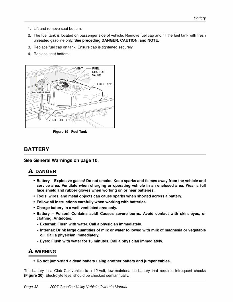
1. Lift and remove seat bottom.
2. The fuel tank is located on passenger side of vehicle. Remove fuel cap and fill the fuel tank with freshunleaded gasoline only. See preceding DANGER, CAUTION, and NOTE.
3. Replace fuel cap on tank. Ensure cap is tightened securely.
4. Replace seat bottom.
BATTERY
See General Warnings on page 10.
ý DANGER
• Battery – Explosive gases! Do not smoke. Keep sparks and flames away from the vehicle andservice area. Ventilate when charging or operating vehicle in an enclosed area. Wear a fullface shield and rubber gloves when working on or near batteries.
• Tools, wires, and metal objects can cause sparks when shorted across a battery.
• Follow all instructions carefully when working with batteries.
• Charge battery in a well-ventilated area only.
• Battery – Poison! Contains acid! Causes severe burns. Avoid contact with skin, eyes, orclothing. Antidotes:
- External: Flush with water. Call a physician immediately.
- Internal: Drink large quantities of milk or water followed with milk of magnesia or vegetableoil. Call a physician immediately.
- Eyes: Flush with water for 15 minutes. Call a physician immediately.
ý WARNING
• Do not jump-start a dead battery using another battery and jumper cables.
The battery in a Club Car vehicle is a 12-volt, low-maintenance battery that requires infrequent checks(Figure 20). Electrolyte level should be checked semiannually.
Figure 19 Fuel Tank
FUELSHUT-OFFVALVE
TO CARBURETOR
VENT TUBES
FUEL TANK
VENT
Page 32 2007 Gasoline Utility Vehicle Owner’s Manual
Battery
1. Turn the key switch to the OFF position and remove the key. Place the Forward/Reverse handle in theNEUTRAL position. Chock the wheels.
2. Access the engine compartment. See WARNING “For vehicles with cargo beds...” on page 10.
2.1. Tilt the bed and ensure that the prop rod is properly engaged.
3. Disconnect the battery cables, negative (–) cable first. See WARNING “To avoid unintentionally start-ing...” on page 10.
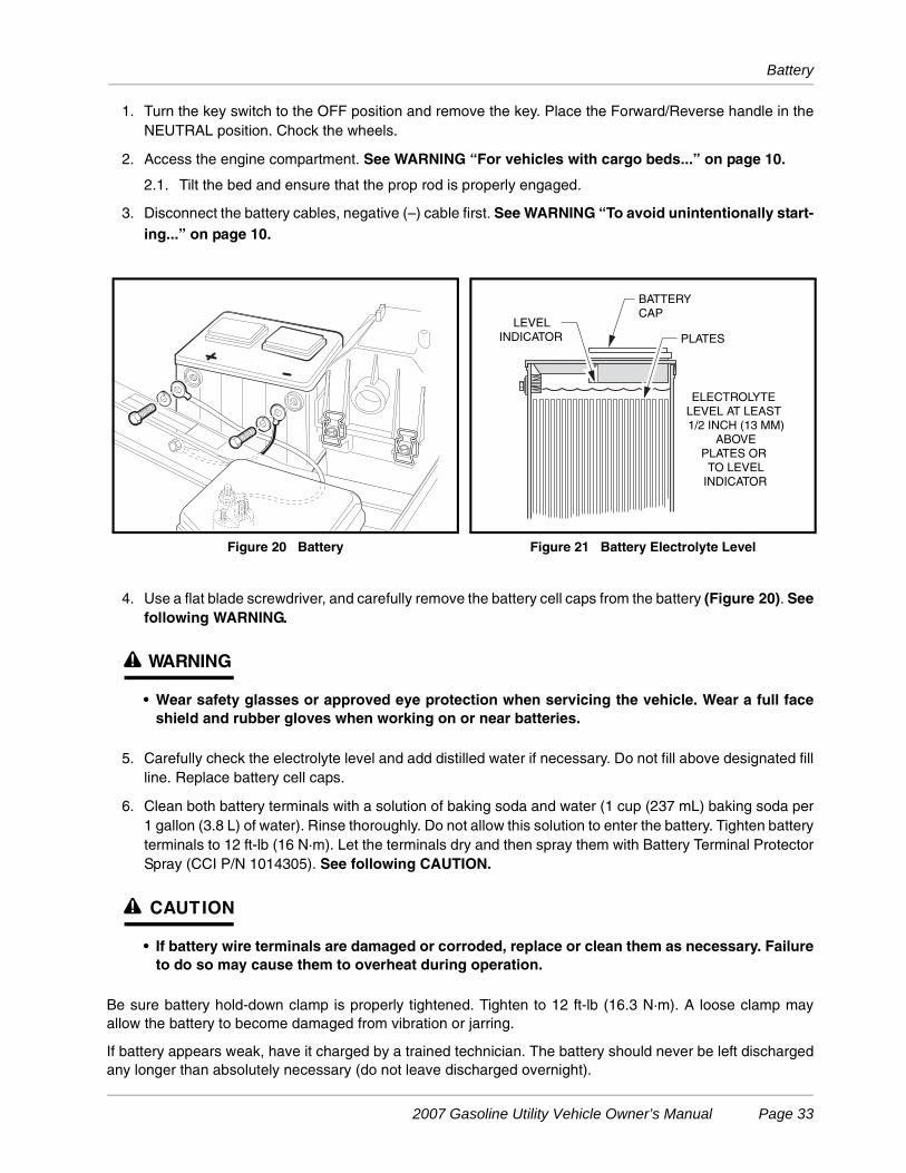
4. Use a flat blade screwdriver, and carefully remove the battery cell caps from the battery (Figure 20). Seefollowing WARNING.
ý WARNING
• Wear safety glasses or approved eye protection when servicing the vehicle. Wear a full faceshield and rubber gloves when working on or near batteries.
5. Carefully check the electrolyte level and add distilled water if necessary. Do not fill above designated fillline. Replace battery cell caps.
6. Clean both battery terminals with a solution of baking soda and water (1 cup (237 mL) baking soda per1 gallon (3.8 L) of water). Rinse thoroughly. Do not allow this solution to enter the battery. Tighten batteryterminals to 12 ft-lb (16 N·m). Let the terminals dry and then spray them with Battery Terminal ProtectorSpray (CCI P/N 1014305). See following CAUTION.
ý CAUTION
• If battery wire terminals are damaged or corroded, replace or clean them as necessary. Failureto do so may cause them to overheat during operation.
Be sure battery hold-down clamp is properly tightened. Tighten to 12 ft-lb (16.3 N·m). A loose clamp mayallow the battery to become damaged from vibration or jarring.
If battery appears weak, have it charged by a trained technician. The battery should never be left dischargedany longer than absolutely necessary (do not leave discharged overnight).
Figure 20 Battery Figure 21 Battery Electrolyte Level
ELECTROLYTE LEVEL AT LEAST 1/2 INCH (13 MM)
ABOVE PLATES OR TO LEVEL
INDICATOR
PLATES
LEVELINDICATOR
BATTERYCAP
2007 Gasoline Utility Vehicle Owner’s Manual Page 33
Cleaning the Vehicle
CLEANING THE VEHICLE
The vehicle is equipped with an ArmorFlex® front body, an all-aluminum rear body, and a powder-coated steelcargo bed. Use a commercially available automotive cleaning solution with a sponge or soft cloth for normalcleaning. A garden hose at normal residential water pressure is adequate. To remove oxidation or discolora-tion from aluminum, use a commercially available aluminum cleaner paste and fine grade (No. 00) steel wool.
Club Car does not recommend any type of pressure washing or steam cleaning. Such a process will exposeelectrical components to moisture. Moisture entering electrical components can result in water damage andsubsequent component failure.
Use non-abrasive wax products. Battery acid, fertilizers, tars, asphalt, creosote, paint, or chewing gum shouldbe removed immediately to prevent possible stains.
The seats of the vehicle will last longer with proper cleaning. Use a solution of 10% liquid soap and warmwater applied with a soft cloth. For imbedded dirt, a soft bristle brush may be used. For heavy soiling, difficultstains, or scratches, blemishes, or other body damage, see Section 4 of the maintenance and service man-ual. See following NOTE.
NOTE: Dispose of waste water properly.
ACCESSORIES
There is a complete line of accessory equipment available from Club Car and our dealers/distributors. Youcan obtain the name and phone number of your closest Club Car contact by visiting our web site at www.club-car.com and clicking the “Dealer Locator” link.
Care should be taken that these accessories are properly installed by trained technicians, and that they areused in the manner for which they were designed. See following WARNING.
ý WARNING
• Custom cab assemblies, canopy tops, weatherproof enclosures, and windshields will notprotect occupants from flying objects.
• If the vehicle is equipped with an electric powered or hydraulic lift bed, remove the bed beforeservicing the bed lift system.
ELECTRIC WINCH ACCESSORY
If your vehicle is equipped with an electric winch, read and follow all manufacturer safety warnings andinstructions in the winch operator manual, as well as the following WARNING and CAUTION statements.Make sure a winch warning decal is affixed to the vehicle on the seat support panel next to the receptacle forthe remote operation switch. See Vehicle Feature Identification beginning on page 4.
The winch kit available from Club Car includes a remote operation switch that enables the operator to moveaway from the vehicle and cable. See following WARNING and CAUTION.
Page 34 2007 Gasoline Utility Vehicle Owner’s Manual
Subsequent Owner Registration
ý WARNING
• Before beginning a winch operation: - Turn the key switch the OFF position, put Forward/Reverse handle in the NEUTRAL
position, and engage the park brake.
- Do not use winch while persons are seated on the vehicle.
- Stand to the side and away from the vehicle to operate winch.
CAUTION
• Use of the winch for an extended period of time could discharge the battery. Keep winchoperations as short as possible, and drive the vehicle for several minutes after the winchoperation to recharge the battery.
SUBSEQUENT OWNER REGISTRATION
In the event a vehicle is bought as a used vehicle, we strongly urge the new owner to register the vehicle withClub Car. This will enable us to contact you if the need arises. Please send your name, address, and serialnumber of the vehicle to Club Car, Inc., P.O. Box 204658, Augusta, Georgia 30917-4658, Attention: VehicleRegistration.
2007 Gasoline Utility Vehicle Owner’s Manual Page 35
Vehicle Specifications
VEHICLE SPECIFICATIONS
SPECIFICATIONS XRT 900 TURF 252CARRYALL 252
POWER SOURCE
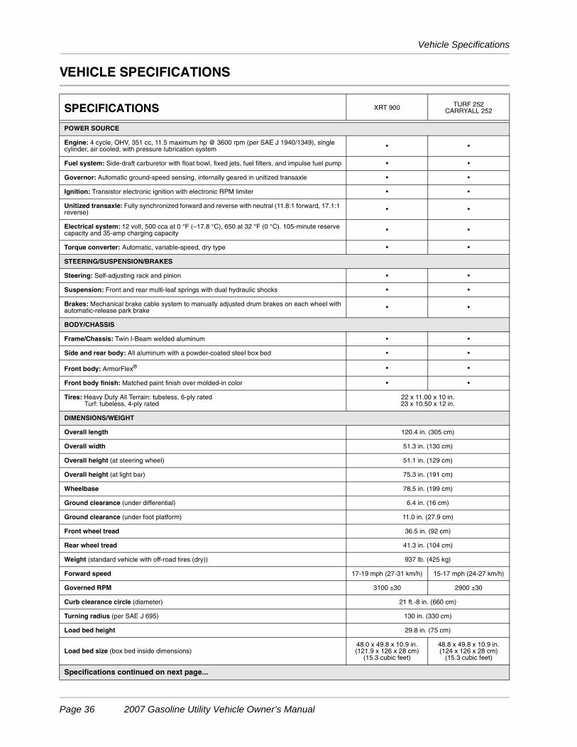
Engine: 4 cycle, OHV, 351 cc, 11.5 maximum hp @ 3600 rpm (per SAE J 1940/1349), single cylinder, air cooled, with pressure lubrication system • •
Fuel system: Side-draft carburetor with float bowl, fixed jets, fuel filters, and impulse fuel pump • •
Governor: Automatic ground-speed sensing, internally geared in unitized transaxle • •
Ignition: Transistor electronic ignition with electronic RPM limiter • •
Unitized transaxle: Fully synchronized forward and reverse with neutral (11.8:1 forward, 17.1:1 reverse) • •
Electrical system: 12 volt, 500 cca at 0 °F (–17.8 °C), 650 at 32 °F (0 °C). 105-minute reserve capacity and 35-amp charging capacity • •
Torque converter: Automatic, variable-speed, dry type • •
STEERING/SUSPENSION/BRAKES
Steering: Self-adjusting rack and pinion • •
Suspension: Front and rear multi-leaf springs with dual hydraulic shocks • •
Brakes: Mechanical brake cable system to manually adjusted drum brakes on each wheel withautomatic-release park brake • •
BODY/CHASSIS
Frame/Chassis: Twin I-Beam welded aluminum • •
Side and rear body: All aluminum with a powder-coated steel box bed • •
Front body: ArmorFlex® • •
Front body finish: Matched paint finish over molded-in color • •
Tires: Heavy Duty All Terrain: tubeless, 6-ply rated Turf: tubeless, 4-ply rated
22 x 11.00 x 10 in.23 x 10.50 x 12 in.
DIMENSIONS/WEIGHT
Overall length 120.4 in. (305 cm)
Overall width 51.3 in. (130 cm)
Overall height (at steering wheel) 51.1 in. (129 cm)
Overall height (at light bar) 75.3 in. (191 cm)
Wheelbase 78.5 in. (199 cm)
Ground clearance (under differential) 6.4 in. (16 cm)
Ground clearance (under foot platform) 11.0 in. (27.9 cm)
Front wheel tread 36.5 in. (92 cm)
Rear wheel tread 41.3 in. (104 cm)
Weight (standard vehicle with off-road tires (dry)) 937 lb. (425 kg)
Forward speed 17-19 mph (27-31 km/h) 15-17 mph (24-27 km/h)
Governed RPM 3100 ±30 2900 ±30
Curb clearance circle (diameter) 21 ft.-8 in. (660 cm)
Turning radius (per SAE J 695) 130 in. (330 cm)
Load bed height 29.8 in. (75 cm)
Load bed size (box bed inside dimensions)48.0 x 49.8 x 10.9 in.(121.9 x 126 x 28 cm)
(15.3 cubic feet)
48.8 x 49.8 x 10.9 in.(124 x 126 x 28 cm)
(15.3 cubic feet)
Specifications continued on next page...
Page 36 2007 Gasoline Utility Vehicle Owner’s Manual
Vehicle Specifications
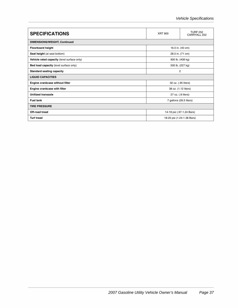
DIMENSIONS/WEIGHT, Continued
Floorboard height 16.0 in. (40 cm)
Seat height (at seat bottom) 28.0 in. (71 cm)
Vehicle rated capacity (level surface only) 900 lb. (408 kg)
Bed load capacity (level surface only) 500 lb. (227 kg)
Standard seating capacity 2
LIQUID CAPACITIES
Engine crankcase without filter 32 oz. (.95 liters)
Engine crankcase with filter 38 oz. (1.12 liters)
Unitized transaxle 27 oz. (.8 liters)
Fuel tank 7 gallons (26.5 liters)
TIRE PRESSURE
Off-road tread 14-18 psi (.97-1.24 Bars)
Turf tread 18-20 psi (1.24-1.38 Bars)
SPECIFICATIONS XRT 900 TURF 252CARRYALL 252
2007 Gasoline Utility Vehicle Owner’s Manual Page 37
Rear Fender Installation
REAR FENDER INSTALLATION
1. Unload the cargo bed.
2. Open the cargo bed and engage the prop rod.
ý WARNING
• Use caution when working under bed. Be sure prop rod is secure. Otherwise the bed couldfall, resulting in severe personal injury or death.
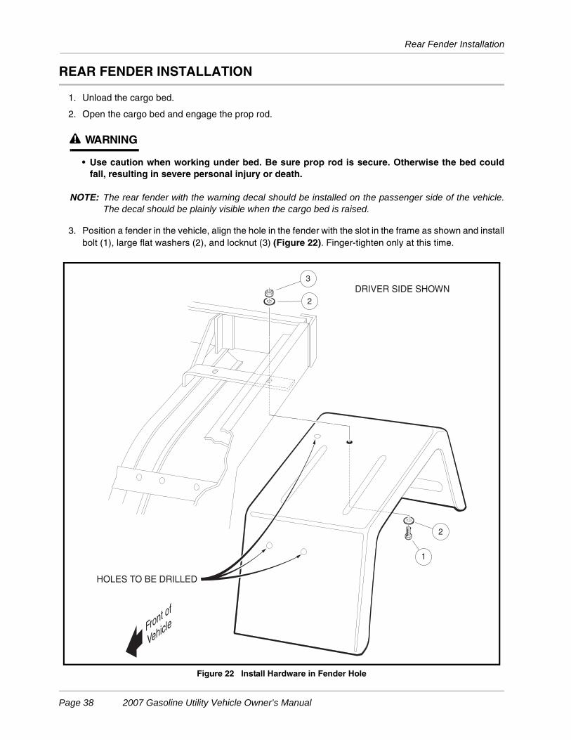
NOTE: The rear fender with the warning decal should be installed on the passenger side of the vehicle.The decal should be plainly visible when the cargo bed is raised.
3. Position a fender in the vehicle, align the hole in the fender with the slot in the frame as shown and installbolt (1), large flat washers (2), and locknut (3) (Figure 22). Finger-tighten only at this time.
Figure 22 Install Hardware in Fender Hole
HOLES TO BE DRILLED
1
3
2
2
Front of
Vehicle
DRIVER SIDE SHOWN
Page 38 2007 Gasoline Utility Vehicle Owner’s Manual
Rear Fender Installation
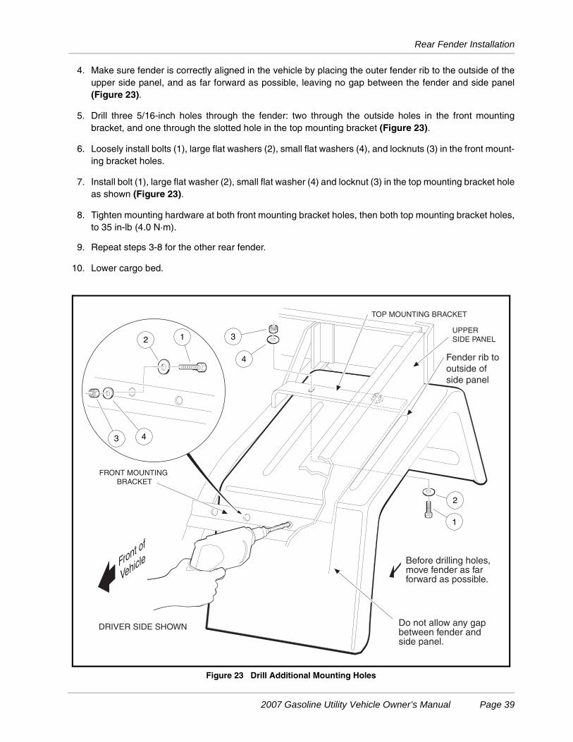
4. Make sure fender is correctly aligned in the vehicle by placing the outer fender rib to the outside of theupper side panel, and as far forward as possible, leaving no gap between the fender and side panel(Figure 23).
5. Drill three 5/16-inch holes through the fender: two through the outside holes in the front mountingbracket, and one through the slotted hole in the top mounting bracket (Figure 23).
6. Loosely install bolts (1), large flat washers (2), small flat washers (4), and locknuts (3) in the front mount-ing bracket holes.
7. Install bolt (1), large flat washer (2), small flat washer (4) and locknut (3) in the top mounting bracket holeas shown (Figure 23).
8. Tighten mounting hardware at both front mounting bracket holes, then both top mounting bracket holes,to 35 in-lb (4.0 N·m).
9. Repeat steps 3-8 for the other rear fender.
10. Lower cargo bed.
Figure 23 Drill Additional Mounting Holes
Front of
Vehicle
DRIVER SIDE SHOWN
2
4
32 1
3 4
1
Before drilling holes, move fender as far forward as possible.
Do not allow any gapbetween fender and side panel.
UPPER
SIDE PANEL
TOP MOUNTING BRACKET
FRONT MOUNTING
BRACKET
Fender rib to
outside of
side panel
2007 Gasoline Utility Vehicle Owner’s Manual Page 39
Wheel and Tire Installation
WHEEL AND TIRE INSTALLATION
NOTE: Upon vehicle delivery, the shipping wheel and tire assemblies must be replaced by the standardwheel and tire assemblies, which are delivered in the vehicle cargo bed.
Do not remove the warning tag attached to the steering wheel until the shipping wheel and tireassemblies have been replaced by standard wheel and tire assemblies.
The front and rear wheels are NOT interchangeable. The rear wheels have a different offset than do the frontwheels; the rear wheels must be installed with the deeper offset facing out.
A rectangular sticker on each wheel designates its correct location on the vehicle.
LF —Left Front (driver side)
RF—Right Front (passenger side)
LR—Left Rear
RR—Right Rear
Standard tires (off-road) are directional and must be installed according to the directional arrow mark on eachtire, (arrow indicates forward rotation of tire) or tread performance will be severely compromised. The optionalturf tire is not directional, and installation is dictated only by correct wheel position, not tire direction.
1. Slightly loosen the lug nuts on all four wheels.
2. Raise one end of the vehicle until the tires are off the ground by approximately six inches. See followingWARNING.
ý WARNING
• Lift only one end of a vehicle at a time. Before lifting, set the park brake when lifting the frontof the vehicle, unload the cargo bed, and chock the wheels that remain on the floor. Use asuitable lifting device (chain hoist or hydraulic floor jack) with 1000 lb. (454 kg) minimumlifting capacity. Do not use lifting device to hold vehicle in raised position. Use approved jackstands of proper weight capacity to support vehicle.
3. Remove the lug nuts and the wheel.
4. Install the correct wheel and tire assembly and tighten lug nuts (using a crisscross pattern) until they aresnug. Arrow indicates forward rotation of tire.
5. Repeat steps 3 and 4 for the other side of the vehicle.
6. Lower the vehicle to the ground and finish tightening lug nuts (using a crisscross pattern) to 55 ft-lb (74.6N·m).
7. Repeat steps 2 through 6 for the other end of the vehicle.
Page 40 2007 Gasoline Utility Vehicle Owner’s Manual
CLUB CAR® LIMITED TWO YEAR WARRANTY FOR 2007TRANSPORTATION AND UTILITY VEHICLES
1. WARRANTY:
CLUB CAR, INC., (“CLUB CAR”) hereby warrants to the Original Retail Purchaser that its new 2007 Model Transportationand Utility Vehicles purchased from CLUB CAR or an authorized dealer shall be free from defects in material andworkmanship under normal use and service as a transportation or utility vehicle for the periods stated below, subject to theprovisions, limitations and exclusions contained in this limited warranty.
LIMITED TWO YEAR / 2000 HOUR WARRANTY: The engine assembly, unitized transaxle assembly (gasoline vehicle),motor, transaxle assembly (electric vehicle), main frame assembly, box bed hydraulic dump kit, Custom Cab assembly anddoors, and Driving Range Protective Enclosure are warranted with respect to parts and labor against defects in material andworkmanship for a period of two years or 2000 hours of operation, whichever first occurs, from the date of purchase.
LIMITED ONE YEAR / 1000 HOUR WARRANTY: All remaining components of the vehicle not specified otherwise, thePortable Refreshment Center, and all other original equipment options and accessories supplied by CLUB CAR arewarranted with respect to parts and labor against defects in material and workmanship for a period of one year or 1000hours of operation, whichever first occurs, from the date of purchase.
This limited warranty covers material, workmanship and repair labor cost as to those items specifically listed above for theperiods specified. Such repair labor shall be performed only by CLUB CAR, its authorized dealers, or a service agencyapproved by CLUB CAR.
IF THE WARRANTY REGISTRATION FORM IS NOT COMPLETED AND RETURNED TO CLUB CAR AT THE TIME OFTHE ORIGINAL RETAIL SALE, PURCHASER MUST PROVIDE PROOF OF DATE OF PURCHASE WITH ANYWARRANTY CLAIM.
2. EXCLUSIONS:
Excluded from any CLUB CAR warranty are all fuses, filters, decals (except safety decals), spark plugs, light bulbs,lubricants, trim pieces, seats, routine wear items such as the charger plug and receptacle, brake shoes, belts, brushes,bushings, engine mounts, mats and pads, maintenance adjustments, cosmetic deterioration, and items which deteriorate orfail due to exposure or ordinary wear and tear. Batteries, battery charger, onboard computer, and solid-state speedcontroller are covered under separate CLUB CAR warranties. Also excluded from any CLUB CAR warranty is damage to avehicle or component resulting from a cause other than a defect including unreasonable or unintended strain or use,improper installation of accessories, installation of parts or accessories that are not original equipment, overloading,accident, alteration, abuse or neglect.
Transportation expenses for warranty services are also excluded from this warranty.
3. VOIDING OF WARRANTY:
THIS AND ANY OTHER WARRANTY SHALL BE VOID IF THE VEHICLE IS ABUSED OR USED IN AN UNINTENDEDMANNER OR SHOWS INDICATIONS THAT IT HAS BEEN ALTERED IN ANY WAY, INCLUDING, BUT NOT LIMITED TO,MODIFICATION OF THE SPEED GOVERNOR, BRAKING SYSTEM, STEERING, TRANSAXLE, OR OTHEROPERATING SYSTEMS OF THE VEHICLE TO CAUSE IT TO PERFORM OUTSIDE CLUB CAR SPECIFICATIONS. THEWARRANTY IS LIKEWISE VOID IF THE VEHICLE INVOLVED SHOWS INDICATIONS THAT REASONABLE ORNECESSARY MAINTENANCE AS OUTLINED IN THE OWNER’S MANUAL AND MAINTENANCE AND SERVICEMANUAL WAS NOT PERFORMED AT THE TIME AND IN THE MANNER SPECIFIED IN SUCH MANUALS.
4. SOLE REMEDY:
CLUB CAR’s liability under this limited warranty, or in any action whether based upon warranty, contract, negligence, strictproduct liability or otherwise, shall be the repair or replacement, at CLUB CAR’s option, of the vehicle or component thereofthat CLUB CAR deems to be defective. Replacement shall mean furnishing, during the applicable limited warranty period, anew vehicle or factory-reconditioned vehicle or component thereof that is identical or reasonably equivalent to the warrantedproduct or component at no cost to the purchaser. Repair shall mean remedying a defect in the vehicle or componentthereof at no cost to the purchaser during the applicable limited warranty period. If CLUB CAR elects to repair the vehicle, itmay provide factory-reconditioned parts or components. All parts and components replaced under warranty shall becomethe property of CLUB CAR.
2007 Gasoline Utility Vehicle Owner’s Manual Page 41
5. HOW TO MAKE A WARRANTY CLAIM:To make a warranty claim under this limited warranty, you must present the vehicle or defective component to an authorizedCLUB CAR dealer or send the defective component, freight prepaid, to WARRANTY SERVICES, CLUB CAR, INC., 4125Washington Road, Evans, Georgia 30809, U.S.A., 706-863-3000.
6. DISCLAIMER:THIS LIMITED WARRANTY IS EXCLUSIVE. CLUB CAR MAKES NO OTHER WARRANTY OF ANY KIND,EXPRESSED OR IMPLIED. ANY IMPLIED WARRANTIES OF MERCHANTABILITY OR FITNESS FOR A PARTICULARPURPOSE WHICH EXCEED THE OBLIGATIONS OR TIME LIMITS STATED IN THIS WARRANTY ARE HEREBYDISCLAIMED BY CLUB CAR AND EXCLUDED FROM THIS WARRANTY. THE PURCHASER AND CLUB CAREXPRESSLY AGREE THAT THE REMEDY OF THE REPLACEMENT OR REPAIR OF THE DEFECTIVE VEHICLE ORCOMPONENT THEREOF IS THE SOLE REMEDY OF THE PURCHASER. CLUB CAR MAKES NO OTHERREPRESENTATION OR WARRANTY OF ANY KIND, AND NO REPRESENTATIVE, EMPLOYEE, OR DEALER OFCLUB CAR HAS THE AUTHORITY TO MAKE OR IMPLY ANY REPRESENTATION, PROMISE OR AGREEMENT,WHICH IN ANY WAY VARIES THE TERMS OF THIS WARRANTY.
7. NO CONSEQUENTIAL DAMAGES:IN NO EVENT SHALL CLUB CAR BE LIABLE FOR ANY INCIDENTAL OR CONSEQUENTIAL DAMAGESINCLUDING, BUT NOT LIMITED TO, LOSS RELATED TO PROPERTY OTHER THAN THE VEHICLE, LOSS OF USE,LOSS OF TIME, INCONVENIENCE, OR ANY OTHER ECONOMIC LOSS.
Some states allow neither limitation on the duration of an implied warranty nor exclusions or limitation of incidental orconsequential damages. Therefore, the above limitations or exclusions may not apply to you.
This warranty gives you specific legal rights, and you may also have other rights, which vary from state to state.
8. INFORMATION:For further information contact WARRANTY SERVICES, CLUB CAR, INC., P.O. Box 204658, Augusta, Georgia 30917-4658, U.S.A., 706-863-3000.
9. WARNING:Any modification or alteration of any vehicle beyond factory specifications, including those that affect the weight distribution,stability, or speed of the vehicle, can cause serious personal injury or death.
Page 42 2007 Gasoline Utility Vehicle Owner’s Manual
CALIFORNIA EMISSION CONTROL WARRANTY STATEMENT
Your new Club Car, Inc. ("CLUB CAR") vehicle engine complies with both the U.S. EPA and State of California emission regulations.
YOUR WARRANTY RIGHTS AND OBLIGATIONS:The California Air Resources Board ("CARB") and CLUB CAR are pleased to explain the emission control system warranty on your 2007 vehicle engine. In California, new small off-roadengines (SORE) must be designed, built and equipped to meet the State's stringent anti-smog standards. CLUB CAR must warrant the emission control system on the vehicle engine forthe periods of time listed below provided there has been no abuse, neglect or improper maintenance of your small off-road engine.Your emission control system may include parts such as the carburetor or fuel-injection system, the ignition system, and catalytic converter. Also included may be hoses, belts,connectors and other emission-related assemblies.Where a warrantable condition exists, CLUB CAR will repair your vehicle engine at no cost to you including diagnosis, parts and labor.
MANUFACTURER'S WARRANTY COVERAGE:This emission control system is warranted for two years. If any emission-related part on your equipment is defective, the part will be repaired or replaced by CLUB CAR.
OWNER'S WARRANTY RESPONSIBILITIES:- As the vehicle engine owner, you are responsible for the performance of the required maintenance listed in your owner's manual. CLUB CAR recommends that you retain all receiptscovering maintenance on your vehicle engine, but CLUB CAR cannot deny warranty solely for the lack of receipts or for your failure to ensure the performance of all scheduledmaintenance.- As the vehicle engine owner, you should however be aware that CLUB CAR may deny you warranty coverage if vehicle engine or a part has failed due to abuse, neglect, impropermaintenance or unapproved modifications.- You are responsible for presenting vehicle engine to a CLUB CAR distribution center as soon as a problem exists. The warranty repairs should be completed in a reasonable amount oftime, not to exceed 30 days.If you have any questions regarding your warranty rights and responsibilities, you should contact WARRANTY SERVICES, CLUB CAR, INC., P.O. Box 204658, Augusta, Georgia309017-4658, U.S.A., 1-706-863-3000.
CLUB CAR EXPLANATION OF EMISSION CONTROL WARRANTY:
1. WARRANTY:CLUB CAR warrants to the ultimate purchaser and each subsequent purchaser that the SORE or equipment is designed, built and equipped so as to conform with all applicableregulations; and free from defects in materials and workmanship that cause the failure of a warranted part to be identical in all material respects to that part as described in CLUB CARsapplication for certification. The warranty period begins on the date the engine or equipment is delivered to an ultimate purchaser or first placed into service. The warranty period is twoyears.
2. COVERAGE:Subject to certain conditions and exclusions as stated below, the warranty on emission-related parts is as follows:(1) Any warranted part that is not scheduled for replacement as required maintenance in the written instructions supplied, is warranted for the warranty period stated above. If the partfails during the period of warranty coverage, the part will be repaired or replaced by CLUB CAR according to subsection (4) below. Any such part repaired or replaced under warranty willbe warranted for the remainder of the period.(2) Any warranted part that is scheduled only for regular inspection in the written instructions supplied is warranted for the warranty period stated above. Any such part repaired orreplaced under warranty will be warranted for the remaining warranty period.(3) Any warranted part that is scheduled for replacement as required maintenance in the written instructions supplied is warranted for the period of time before the first scheduledreplacement date for that part. If the part fails before the first scheduled replacement, the part will be repaired or replaced by CLUB CAR according to subsection (4) below. Any suchpart repaired or replaced under warranty will be warranted for the remainder of the period prior to the first scheduled replacement point for the part.(4) Repair or replacement of any warranted part under the warranty provisions herein must be performed at a warranty station* at no charge to the owner. (5) Notwithstanding the provisions herein, warranty services or repairs will be provided at all of our distribution centers that are franchised to service the subject engines or equipment.(6) The engine or equipment owner will not be charged for diagnostic labor that is directly associated with diagnosis of a defective, emission-related warranted part, provided that suchdiagnostic work is performed at a warranty station*.(7) CLUB CAR is liable for damages to other engine or equipment components proximately caused by a failure under warranty of any warranted part.(8) Throughout the engine or equipment warranty period stated above, CLUB CAR will maintain a supply of warranted parts sufficient to meet the expected demand for such parts.(9) Any replacement part may be used in the performance of any warranty maintenance or repairs and must be provided without charge to the owner. Such use will not reduce thewarranty obligations of CLUB CAR(10) Add-on or modified parts that are not exempted by the Air Resources Board may not be used. The use of any non-exempted add-on or modified parts by the ultimate purchaser willbe grounds for disallowing a warranty claims. CLUB CAR will not be liable to warrant failures of warranted parts caused by the use of a non-exempted add-on or modified part.*CLUB CAR, its authorized dealers, or a service agency approved by CLUB CAR.
ITEMS COVERED BY THIS WARRANTY:The repair or replacement of any warranted part otherwise eligible for warranty coverage may be excluded from such warranty coverage if CLUB CAR demonstrates that the engine orequipment has been abused, neglected, or improperly maintained, and that such abuse, neglect, or improper maintenance was the direct cause of the need for repair or replacement ofthe part. That notwithstanding, any adjustment of a component that has a factory installed, and properly operating, adjustment limiting device is still eligible for warranty coverage. Thefollowing emission warranty parts list are covered:
SYSTEMS COVERED PARTS DESCRIPTIONFuel Metering Carburetor assembly, fuel injection pump, fuel injection nozzle, fuel regulatorExhaust CatalystAir Induction Air filter housing, air filter*, crankcase breather tubeIgnition Flywheel magneto, ignition pulse generator, ignition coil assembly, ignition control module, spark plug cap, spark plug*Positive Crankcase Ventilation (PCV) System PCV valve, oil filler capMisc. Parts Belts, fuel hose, hosing, tubing, fittings, seals, gasket, and clamps associated with the above systemsEmission-related parts will vary between vehicles; therefore, certain vehicles my not include all of the listed parts or may include equivalent parts.
3. EXCLUSIONS:Excluded from this warranty is damage to a vehicle or component resulting from a cause other than a defect including unreasonable or unintended strain or use, improper installation ofaccessories, installation of parts or accessories that are not original equipment, overloading, accident, alteration, abuse or neglect. This warranty covers only those failures resulting fromdefects in material or workmanship.Transportation expenses for warranty services are also excluded from this warranty.
4. VOIDING OF WARRANTY:THIS AND ANY OTHER WARRANTY SHALL BE VOID IF THE VEHICLE IS ABUSED OR USED IN AN UNINTENDED MANNER OR SHOWS INDICATIONS THAT IT HAS BEENALTERED IN ANY WAY, INCLUDING, BUT NOT LIMITED TO, MODIFICATION OF THE SPEED GOVERNOR, BRAKING SYSTEM, STEERING, TRANSAXLE, OR OTHEROPERATING SYSTEMS OF THE VEHICLE TO CAUSE IT TO PERFORM OUTSIDE CLUB CAR SPECIFICATIONS. THE WARRANTY IS LIKEWISE VOID IF THE VEHICLEINVOLVED SHOWS INDICATIONS THAT REASONABLE OR NECESSARY MAINTENANCE AS OUTLINED IN THE OWNERS MANUAL AND MAINTENANCE AND SERVICEMANUAL WAS NOT PERFORMED AT THE TIME AND IN THE MANNER SPECIFIED IN SUCH MANUALS.
5. NO CONSEQUENTIAL DAMAGES:In no event shall Club Car be liable for any incidental or consequential damages including, but not limited to, loss related to property other than the vehicle, loss of use, loss of time,inconvenience, or any other economic loss. This warranty is applicable only where the California or U.S. EPA emission control system warranty regulation is in effect.
6. HOW TO MAKE A WARRANTY CLAIM:To make a warranty claim under this limited warranty, you must present the vehicle or defective component to an authorized CLUB CAR dealer or send the defective component, freightprepaid, to WARRANTY SERVICES, CLUB CAR, INC., 4125 Washington Road, Evans, Georgia 30809, U.S.A., 706-863-3000.IF THE WARRANTY REGISTRATION FORM IS NOT COMPLETED AND RETURNED TO CLUB CAR AT THE TIME OF THE ORIGINAL RETAIL SALE, PURCHASER MUSTPROVIDE PROOF OF DATE OF PURCHASE WITH ANY WARRANTY CLAIM.
2007 Gasoline Utility Vehicle Owner’s Manual Page 43
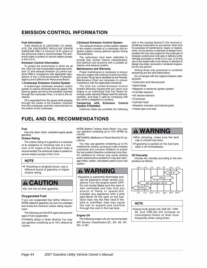
FUEL AND OIL RECOMMENDATIONS
Fuel
Use only clean, fresh, unleaded regular gradegasoline.
Octane Rating
The octane rating of a gasoline is a measure
of its resistance to “knocking”.Use of a mini-
mum of 87 octane of the anti-knock index is
recommended.The anti-knock index is posted on
service station pumps in the U.S.A.
Oxygenated Fuel
If you use oxygenated fuel (either ethanol or
MTBE added to gasoline), be sure it is unleaded
and meets the minimum octane rating require-
ment.
The following are the EPA approved percent-
ages of fuel oxygenates.
ETHANOL:(Ethyl or Grain Alcohol) You may
use gasoline containing up to 10% ethanol by
volume.
MTBE:(Methyl Tertiary Butyl Ether) You mayuse gasoline containing up to 15% MTBE byvolume.
METHANOL:(Methanol or Wood Alcohol) 5% byvolume.
You may use gasoline containing up to 5%methanol by volume, as long as it also containscosolvents and corrosion inhibitors to protectthe fuel system.Gasoline containing more than5% methanol by volume may cause startingand/or performance problems.It may also dam-age metal, rubber, and plastic parts of your fuelsystem.
Engine Oil
The following engine oils are recommended.
API Service Classification:SC, SD, SE, SF,SG, or SH.
Oil ViscosityChoose the viscosity according to the tem-
perature as follows:
Fuel Information
THIS VEHICLE IS CERTIFIED TO OPER-ATE ON UNLEADED REGULAR GRADEGASOLINE ONLY.A minimum of 87 octane ofthe anti-knock index is recommended.The anti-knock index is posted on service station pumpsin the U.S.A.
Emission Control Information
To protect the environment in which we alllive, Club Car has incorporated crankcase emis-sion (1) and exhaust emission (2) control sys-tems (EM) in compliance with applicable regu-lations of the U.S.Environmental ProtectionAgency and California Air Resources Board.
1.Crankcase Emission Control System
A sealed-type crankcase emission controlsystem is used to eliminate blow-by gases.Theblow-by gases are led to the breather chamberthrough the crankcase.Then, it is led to the aircleaner.
Oil is separated from the gases while passingthrough the inside of the breather chamberfrom the crankcase, and then returned back tothe bottom of the crankcase.
2.Exhaust Emission Control System
The exhaust emission control system appliedto this engine consists of a carburetor and anignition system having optimum ignition timingcharacteristics.
The carburetors have been calibrated toprovide lean air/fuel mixture characteristicsand optimum fuel economy with a suitable aircleaner and exhaust system.
Maintenance and Warranty
Proper maintenance is necessary to ensurethat your engine will continue to have low emis-sion levels.Those items identified by the PeriodicMaintenance Chart are necessary to ensurecompliance with the applicable standards.
The Club Car Limited Emission ControlSystem Warranty requires that you return yourengine to an authorized Club Car Dealer forremedy under warranty.Please read the warrantycarefully, and keep it valid by complying withthe owner’s obligations it contains.
Tampering with Emission ControlSystem Prohibited
California State law prohibits the following
acts or the causing thereof:(1) the removal orrendering inoperative by any person other thanfor purposes of maintenance, repair, or replace-ment, of any device or element of design incor-porated into any new engine for the purposes ofemission control prior to its sale or delivery to theultimate purchaser or while it is in use, or (2) theuse of the engine after such device or element ofdesign has been removed or rendered inopera-tive by any person.
Among those acts presumed to constitutetampering are the acts listed below:
Do not tamper with the original emission relat-ed parts:
• Carburetor and internal parts
• Spark plugs
• Magneto or electronic ignition system
• Fuel filter element
• Air cleaner element
• Crankcase
• Cylinder head
• Breather chamber and internal parts
• Intake pipe and tube
EMISSION CONTROL INFORMATION
NOTE
•If “knocking or pinging”occurs, use adifferent brand of gasoline or higheroctane rating.
•Do not mix oil with gasoline.
•Gasoline is extremely flammable andcan be explosive under certain con-ditions.Turn the engine switch OFF.Do not smoke.Make sure the area iswell ventilated and free from anysource of f lame or sparks;thisincludes any appliance with a pilotlight.Never fill the tank so the fuellevel rises into the filler neck.If thetank is overfilled, heat may causethe fuel to expand and overflowthrough the vent in the fuel tank.
•After refueling, make sure the tankcap is closed securely.
•If gasoline is spilled on the fuel tankwipe it off immediately.
CAUTION
WARNING
WARNING
NOTE
•Using multi-grade oils (5W-20, 10W-30, and 10W-40) will increase oilconsumption.Check oil level morefrequently when using them.
°
°
°° ° ° ° °C
° ° ° ° °° °
-20 C -10 C 0 C 10 C 20 C
-4 F F 32 F 68 F 86 F 104 F
SAE 5W-20
SAE 10W-30/SAE 10W-40
SAE 30
SAE 40
30 40
14 50 F
Page 44 2007 Gasoline Utility Vehicle Owner’s Manual
Please fax a copy of this page to (706) 228-2662.
Thank You!
Club Car Technical Publication Department
1. Ease of Understanding
2. Ease of Finding Information
3. Clarity of Illustrations
4. Periodic Service and Periodic Lubrication Schedules
Poor Fair Average Good Excellent
Comments/Suggestions
In order to help us better serve you, please rate this publication in the following catgories:
Your Comments Are Appreciated
Please select your category:
Distributor/Dealer
Individual Owner
Club Car Associate/Representative
Technician
Golf Course Superintendent
Other: _____________________
2007 Gasoline Utility Vehicle Owner’s Manual Page 45

Page 46 2007 Gasoline Utility Vehicle Owner’s Manual


Club Car, Inc.
P.O. Box 204658
Augusta, GA 30917-4658
USA
Web www.clubcar.com
Phone 1.706.863.3000
1.800.ClubCar
Intl’l +1 706.863.3000
Fax 1.706.863-5808
Publication Part Number 103218315
Edition Code 0706B0706A