oil level control booklet - sid harvey'sorders.sidharvey.com/images/specs/s-9130.pdfoil level...
TRANSCRIPT

2-025-001 REV. N
CHATHAM, IL U.S.A. 62629
OIL LEVELCONTROLBOOKLET
INSTALLATION AND SERVICE INSTRUCTIONS
SECTION TITLE PAGESI INTRODUCTION 1II TYPES OF SYSTEMS 2III OIL SEPARATORS 3IV OIL RESERVOIRS 4V MECHANICAL OIL REGULATORS 5-7VI ELECTRO-MECHANICAL REGULATORS 8-9VII ADAPTER KITS 10VIII SERVICE/TROUBLESHOOTING 11-12IX REPLACEMENT PARTS 13

HENRY TECHNOLOGIESOIL CONTROL INSTRUCTION BOOKLET
Page 1 5/7//98
SECTION I - INTRODUCTION
This oil control booklet covers oil control systems for reciprocating, rotary, or scroll compressors using halocarbon refrigerantsonly. Do not use this guide or the products contained within for screw or rotary-vane compressors or for ammonia systems.
A proper oil control system is essential to insure compressor lubrication and energy efficient cooling. An oil control system canbe a very cost effective alternative to replacing expensive compressors due to loss of oil. If installed correctly, an oil control system cangive years of trouble-free operation and protect compressors from lack of oil and varying oil levels with little or no maintenance. Oiltraveling through the system tends to build up in the evaporator, condenser, and vessels of an air-conditioning or refrigeration system.This causes a lack of oil return to the compressor until finally, in most cases, a large amount returns as a “slug” of oil. A slug of oil downthe suction line can be just as damaging to the compressor as a slug of liquid refrigerant. This delay in oil return requires an additionalamount of oil to be added to the system, depending on the size of the system, the piping, the temperatures, the miscibility of therefrigerant/oil mix, and the refrigerant velocity. In many systems, this extra oil can amount to 15 gallons or more.
By removing oil from the discharge gas of compressors, not only is the oil level for each compressor more accurately controlled,the efficiency of the system is increased. Oil does not change phase from liquid to gas in an air-conditioning or refrigeration system andtherefore makes a very poor refrigerant. Due to this, it will not pick up and reject heat nearly as well as refrigerant and a system willactually have to cool the oil as it tries to cool the evaporator, reducing the amount of heat the refrigerant can pick up. Oil also takes upvolume through the system that otherwise could be filled with refrigerant, causing higher mass flow rates through the system.Additionally, oil tends to film the condenser tubing walls lowering heat transfer and as oil and refrigerant exits the expansion valve, theoil will foam, insulating the evaporator walls and again lowering heat transfer. In this manner, oil traveling through the system can affectefficiency very dramatically in a variety of ways.
Note, however, that an oil control system does not replace the need for proper system design. An oil control system willdrastically reduce the amount of oil going through the system, however, suction traps, correct piping, and proper sizing of valves,controls, and components must still be implemented to insure the system will work properly.
GENERAL INFORMATIONIn all oil control systems, a means to feed oil to the compressors without bypassing hot gas to the crankcases is needed. In single
compressor or low-pressure systems, an internal float in the oil separator accomplishes this. These floats will open to feed a few ouncesof oil and close once the oil level has dropped. The float cycles as needed to return as much oil as the separator separates from thedischarge.
It is required that all oil systems have a discharge check valve installed between the oil separator and the condenser. Thisprevents refrigerant migration and back feeding to the oil separator during compressor off cycles. If this check valve is not installed, theseparator can feed excessive liquid refrigerant to the compressor once the compressor starts, causing dilution of the oil, excessivefoaming, erratic oil pressures, and possible compressor damage.
Due to the reduced amount of oil going through the system, a means to remove debris from the oil is required in the oil controlsystem, since the oil will not travel through the suction and liquid line filters. An oil strainer can be used to pick up debris in mostsystems and one should be placed in each oil line to every compressor. For systems using POE oil, a filter or filter-drier must be used toprevent clogging of valves. Polyolester (POE) oil is a very good solvent and will scavenge the system of debris that mineral oil will not.This debris can lead to clogging of components in the oil control system as well as the refrigeration system as a whole. Insure that thefilters throughout the whole system are changed three times in the first three months to avoid problems.
Never remove or loosen components in the system when the system is under pressure or contains refrigerant. Loss of refrigerantor personal injury may result.
All components are labeled with a maximum working pressure that must not be exceeded. All components are built with a factorof safety before rupturing, however, permanent damage to the component may occur if the maximum working pressure for anycomponent is exceeded.
When installing or servicing a component, always leak test and then evacuate (pull into vacuum) the system prior to addingrefrigerant to insure all joints are sealed and will prevent loss of refrigerant.
HENRY TECHNOLOGIESOIL CONTROL INSTRUCTION BOOKLET
Page 2 5/7//98
SECTION II - TYPES OF SYSTEMS
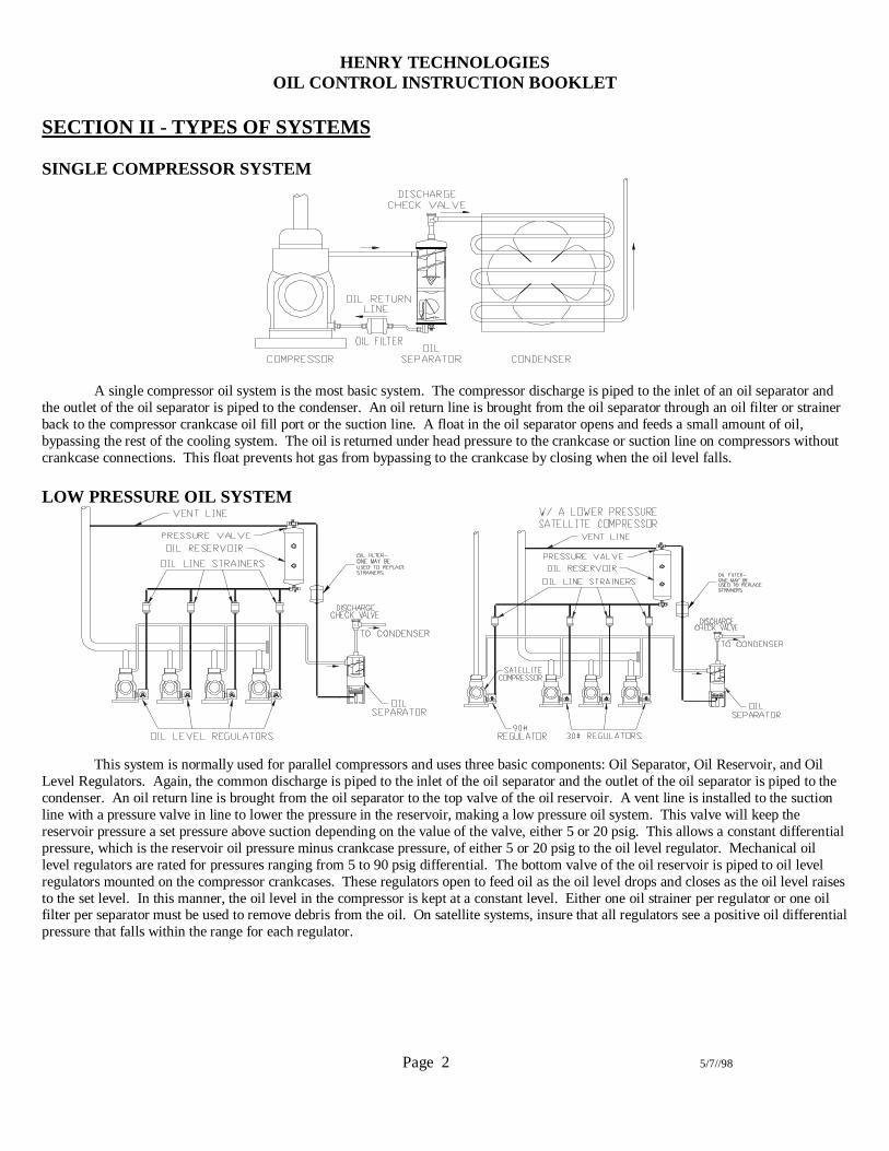
SINGLE COMPRESSOR SYSTEM
A single compressor oil system is the most basic system. The compressor discharge is piped to the inlet of an oil separator andthe outlet of the oil separator is piped to the condenser. An oil return line is brought from the oil separator through an oil filter or strainerback to the compressor crankcase oil fill port or the suction line. A float in the oil separator opens and feeds a small amount of oil,bypassing the rest of the cooling system. The oil is returned under head pressure to the crankcase or suction line on compressors withoutcrankcase connections. This float prevents hot gas from bypassing to the crankcase by closing when the oil level falls.
LOW PRESSURE OIL SYSTEM
This system is normally used for parallel compressors and uses three basic components: Oil Separator, Oil Reservoir, and OilLevel Regulators. Again, the common discharge is piped to the inlet of the oil separator and the outlet of the oil separator is piped to thecondenser. An oil return line is brought from the oil separator to the top valve of the oil reservoir. A vent line is installed to the suctionline with a pressure valve in line to lower the pressure in the reservoir, making a low pressure oil system. This valve will keep thereservoir pressure a set pressure above suction depending on the value of the valve, either 5 or 20 psig. This allows a constant differentialpressure, which is the reservoir oil pressure minus crankcase pressure, of either 5 or 20 psig to the oil level regulator. Mechanical oillevel regulators are rated for pressures ranging from 5 to 90 psig differential. The bottom valve of the oil reservoir is piped to oil levelregulators mounted on the compressor crankcases. These regulators open to feed oil as the oil level drops and closes as the oil level raisesto the set level. In this manner, the oil level in the compressor is kept at a constant level. Either one oil strainer per regulator or one oilfilter per separator must be used to remove debris from the oil. On satellite systems, insure that all regulators see a positive oil differentialpressure that falls within the range for each regulator.

HENRY TECHNOLOGIESOIL CONTROL INSTRUCTION BOOKLET
Page 3 5/7//98
SECTION III - OIL SEPARATORS
OIL SEPARATOR INSTALLATION(used on Single Compressor or Low Pressure Systems only)
1. S-1900, S-5200, S-5700 series oil separators - Remove the plastic shipping plug from the bottom flange of the oil separator and replacewith a steel pipe plug. Use Loctite #12929 sealant or equivalent and torque to 13-15 ft-lbs.2. A valve may be added if desired to the female 1/8” NPTF oil drain fitting on the bottom of S-1900, S-5700, S-5100, and S-5200 seriesoil separators. This fitting opens into the tank and will drain oil completely from the separator. This feature is useful for frequent oilchange-outs3. Precharge the oil separator with the same oil used in the system. This oil may be poured through the inlet or outlet fitting on all catalogseparators. This oil precharge is the amount that is needed to just float the needle valve float. This amount of oil will stay in the oilseparator when in operation and will seal the needle and prevent damage to the float mechanism. There have been instances that the floathas been damaged by the turbulent hot gas bouncing the float if the separator was not precharged, which has caused the float mechanismto leak.
HELICAL MODEL NO. OIL PRECHARGE CONVENTIONAL NO. OIL PRECHARGES-5180, S-5181 4 oz. / 11 cl S-5500 series 12 oz. / 34 cl
S-5182, 85, 87, 88 14 oz. / 40 cl S-5800 series 12 oz. / 34 clS-5190, 92, 94 40 oz. / 114 cl S-5600 series 30 oz. / 86 cl
S-5200/S-5410 series 25 oz. / 71 cl S-1900/S-5700 series 25 oz. / 71 cl
4. Install oil separator vertically between compressor and condenser, reasonably close to the compressor to insure that the discharge gas inthe separator remains super-heated. Make sure that proper piping practices are used to prevent excessive vibration in the discharge line.If used, vibration eliminators and mufflers should be piped before the oil separator. If the oil separator has a bottom stud, the stud must bein an opening large enough to receive the stud and its weld fillet. Use as much of the bottom for bearing as possible: this tends to arrestvibration. Tighten nut to 15 ft-lbs. torque. If the separator has mounting legs, insure that the legs are properly attached to the mountingsurface by bolts or welds. DO NOT SUPPORT THE OIL SEPARATOR BY THE DISCHARGE LINE ALONE! This will causeabnormal stress and fatigue on the line and fittings and may cause failure of the joints.5. Attach compressor discharge line to INLET of the oil separator and the OUTLET of the separator to a discharge check valve and thento the condenser. The check valve will prevent liquid refrigerant migrating and back feeding from the condenser.6. The oil return fitting is normally a 3/8” S.A.E. male flare fitting or a 3/8” ODS fitting on “X” versions. A 3/8” line should be installedfrom this fitting to either the compressor fill port or suction line on a single compressor system or the top valve on the oil reservoir in alow pressure oil system. A sight glass in the oil return line is a useful way to view oil feeding from the oil separator for trouble-shooting.A 3/8” liquid line sight glass may be used for this. If installing an oil separator in an existing single compressor system with either no oilseparator or an inefficient separator, it is suggested to run the oil return line to the suction line of the compressor and install a oil drainvalve either in the compressor crankcase (preferred) or in the 1/8” NPTF oil drain (if available) of the separator. This will allow you tosee when excess oil is flooding the separator and compressor and to drain this oil from the system. A hand valve may also be installed inthe oil return line to service the separator.7. Silver braze the connections with a standard alloy used to join copper tubing to steel for refrigeration applications. Tin-Lead soldersare NOT acceptable. Clean flux from connections after soldering/brazing. On oil separators with ODS connections located on the flangeplate, care must be taken to prevent the gasket from temperatures over 300 degrees F. Place a wet rag on the header plate to keep it coolwhile soldering or brazing.8. Insulate the oil separator and add a heat band when the oil separator is mounted in a potentially cold ambient area or if the oil separatoris in the air stream of the condenser fans. This will prevent refrigerant from condensing in the separator while the system is running. 4”heat bands may be added to the sump of replaceable float separators.
HENRY TECHNOLOGIESOIL CONTROL INSTRUCTION BOOKLET
Page 4 5/7//98
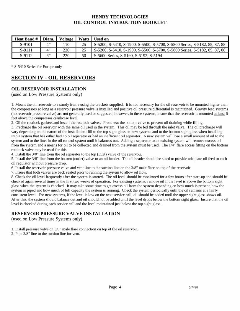
Heat Band # Diam. Voltage Watts Used onS-9101 4” 110 25 S-5200, S-5410, S-1900, S-5500, S-5700, S-5800 Series, S-5182, 85, 87, 88S-9111 4” 220 25 S-5200, S-5410, S-1900, S-5500, S-5700, S-5800 Series, S-5182, 85, 87, 88S-9112 6” 220 50 S-5600 Series, S-5190, S-5192, S-5194
* S-5410 Series for Europe only
SECTION IV - OIL RESERVOIRS
OIL RESERVOIR INSTALLATION(used on Low Pressure Systems only)
1. Mount the oil reservoir to a sturdy frame using the brackets supplied. It is not necessary for the oil reservoir to be mounted higher thanthe compressors so long as a reservoir pressure valve is installed and positive oil pressure differential is maintained. Gravity feed systems(no reservoir pressure valve) are not generally used or suggested, however, in these systems, insure that the reservoir is mounted at least 6feet above the compressor crankcase level.2. Oil the rotalock gaskets and install the rotalock valves. Front seat the bottom valve to prevent oil draining while filling.3. Precharge the oil reservoir with the same oil used in the system. This oil may be fed through the inlet valve. The oil precharge willvary depending on the nature of the installation: fill to the top sight glass on new systems and to the bottom sight glass when installinginto a system that has either had no oil separator or had an inefficient oil separator. A new system will lose a small amount of oil to thesystem and to the lines in the oil control system until it balances out. Adding a separator to an existing system will remove excess oilfrom the system and a means for oil to be collected and drained from the system must be used. The 1/4” flare access fitting on the bottomrotalock valve may be used for this.4. Install the 3/8” line from the oil separator to the top (inlet) valve of the reservoir.5. Install the 3/8” line from the bottom (outlet) valve to an oil header. The oil header should be sized to provide adequate oil feed to eachoil regulator without pressure drop.6. Install the reservoir pressure valve and vent line to the suction line on the 3/8” male flare on top of the reservoir.7. Insure that both valves are back seated prior to running the system to allow oil flow.8. Check the oil level frequently after the system is started. The oil level should be monitored for a few hours after start-up and should bechecked again several times in the first two weeks of operation. For existing systems, remove oil if the level is above the bottom sightglass when the system is checked. It may take some time to get excess oil from the system depending on how much is present, how thesystem is piped and how much of full capacity the system is running. Check the system periodically until the oil remains at a fairlyconsistent level. For new systems, if the level is low on the next service call, oil should be added until the upper sight glass shows oil.After this, the system should balance out and oil should not be added until the level drops below the bottom sight glass. Insure that the oillevel is checked during each service call and the level maintained just below the top sight glass.
RESERVOIR PRESSURE VALVE INSTALLATION(used on Low Pressure Systems only)
1. Install pressure valve on 3/8” male flare connection on top of the oil reservoir.2. Pipe 3/8” line to the suction line for vent.

HENRY TECHNOLOGIESOIL CONTROL INSTRUCTION BOOKLET
Page 5 5/7//98
SECTION V - MECHANICAL OIL LEVEL REGULATORS(used on Low Pressure Systems only)
REGULATORMODEL NO.
CONNECTIONSIZE
OPER. PRESSUREDIFFERENTIAL, psig
OIL LEVEL,SIGHT GLASS
S-9010 3 BOLT 1 7/8” B.C. 5-30 ½S-9010A 4 BOLT 50mm B.C. 5-30 ½S-9015 ¾” NPTF FEMALE 5-30 ½S-9090 3 BOLT 1 7/8” B.C. 5-90 ADJUSTABLE * +
S-9090A 4 BOLT 50 mm B.C. 5-90 ADJUSTABLE * +S-9110 3 BOLT 1 7/8” B.C. 5-30 ½S-9120 3 BOLT 1 7/8” B.C. 5-30 ¼ +S-9130 3 BOLT 1 7/8” B.C. 5-90 ADJUSTABLE * +S-9190 3 BOLT 1 7/8” B.C. 30-90 ADJUSTABLE * +
* These adjustable oil regulators are designed to feed oil between 1/4 and 5/8 glass levels at the variousspecified pressure differentials. The regulator may adjust beyond this range due to the actual oil pressure.
Maintain all adjustable regulator levels according to compressor manufacturer’s specifications.+ Do not operate ANY regulator at 1/4 sight glass when using an adapter with inside diameter
smaller than the regulator flange port.Note: S-9010A and S-9090A 4 bolt 50mm B.C. for European use only (Bitzer Compressors)

HENRY TECHNOLOGIESOIL CONTROL INSTRUCTION BOOKLET
Page 6 5/7//98
GENERAL INFORMATIONAll regulators have a operating pressure differential range that should not be confused with its working pressure. The operating
differential is the difference of pressure between the oil feeding into the regulator and the component where the regulator is controlling oillevel. Specifically, the reservoir pressure minus the crankcase pressure. If the differential pressure is too low for that regulator,insufficient oil flow to the compressor may result. If the differential pressure is too high, the regulator will over-fill.
Adjustable regulators include an adjustment mechanism to raise or lower the oil set point. Our exclusive design eliminates theneed to shut the system down and disconnect the oil feed lines in order to adjust the oil level regulator. The oil level may be adjustedwhile the system is under pressure and running. Adjust the oil level by removing the seal cap, the locking disk (S-9130 & S-9190 seriesonly), and rotating the adjustment clockwise to lower, counter clockwise to raise the oil level. Replace cap and locking disk when done.Each full turn of the adjustment mechanism moves the oil level approximately 1/16”. Oil levels on these regulators are typically factoryset just below 1/2 sight glass.
ASSEMBLY OF OIL LEVEL REGULATORS ON COMPRESSORS WITH 3 BOLT 1 7/8”B.C.
1. Remove compressor sight glass.2. Lightly oil and insert one of the o-rings supplied in the groove of the regulator flange to be connected to the compressor. Assemblesupplied bolts and nuts to the flange and evenly and alternately torque bolts to approximately 5 ft-lbs.3. Lightly oil and insert another supplied o-ring in the compressor sight glass groove. Lightly oil and insert the supplied “quad-ring” inthe regulator flange groove. The o-ring and “quad-ring” nestle within each other and together will seal the two grooves. Assemble the 3bolt compressor sight glass to the oil regulator and install supplied bolts and nuts. Evenly and alternately torque bolts to approximately 5ft-lbs.4. Install oil supply line from oil reservoir to 3/8” male flare inlet on top of the regulator.5. If an equalization connection is supplied, install oil equalization line between regulators if desired, otherwise, leave this connectionsealed.6. Insure that the regulator is level. Failure to level the regulator may cause false visual oil levels in the sight glass and can causeinsufficient oil levels. If the regulator is not level, check and level the compressor as necessary.7. Allow oil to feed and insure that the oil level matches the compressor manufacturer’s suggestions. Some suggested oil levels areincluded below in the adapter kit table. DO NOT LEAVE SYSTEM UNATTENDED UNTIL YOU KNOW THAT THE REGULATORIS INSTALLED AND LEVEL CHECKED CORRECTLY.
HENRY TECHNOLOGIESOIL CONTROL INSTRUCTION BOOKLET
Page 7 5/7//98
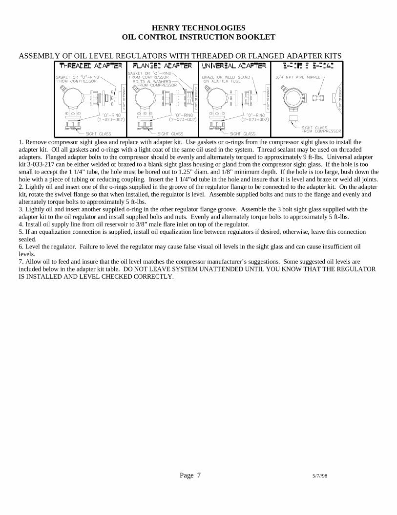
ASSEMBLY OF OIL LEVEL REGULATORS WITH THREADED OR FLANGED ADAPTER KITS
1. Remove compressor sight glass and replace with adapter kit. Use gaskets or o-rings from the compressor sight glass to install theadapter kit. Oil all gaskets and o-rings with a light coat of the same oil used in the system. Thread sealant may be used on threadedadapters. Flanged adapter bolts to the compressor should be evenly and alternately torqued to approximately 9 ft-lbs. Universal adapterkit 3-033-217 can be either welded or brazed to a blank sight glass housing or gland from the compressor sight glass. If the hole is toosmall to accept the 1 1/4” tube, the hole must be bored out to 1.25” diam. and 1/8” minimum depth. If the hole is too large, bush down thehole with a piece of tubing or reducing coupling. Insert the 1 1/4”od tube in the hole and insure that it is level and braze or weld all joints.2. Lightly oil and insert one of the o-rings supplied in the groove of the regulator flange to be connected to the adapter kit. On the adapterkit, rotate the swivel flange so that when installed, the regulator is level. Assemble supplied bolts and nuts to the flange and evenly andalternately torque bolts to approximately 5 ft-lbs.3. Lightly oil and insert another supplied o-ring in the other regulator flange groove. Assemble the 3 bolt sight glass supplied with theadapter kit to the oil regulator and install supplied bolts and nuts. Evenly and alternately torque bolts to approximately 5 ft-lbs.4. Install oil supply line from oil reservoir to 3/8” male flare inlet on top of the regulator.5. If an equalization connection is supplied, install oil equalization line between regulators if desired, otherwise, leave this connectionsealed.6. Level the regulator. Failure to level the regulator may cause false visual oil levels in the sight glass and can cause insufficient oillevels.7. Allow oil to feed and insure that the oil level matches the compressor manufacturer’s suggestions. Some suggested oil levels areincluded below in the adapter kit table. DO NOT LEAVE SYSTEM UNATTENDED UNTIL YOU KNOW THAT THE REGULATORIS INSTALLED AND LEVEL CHECKED CORRECTLY.

HENRY TECHNOLOGIESOIL CONTROL INSTRUCTION BOOKLET
Page 8 5/7//98
SECTION VI - ELECTRO-MECHANICAL OIL LEVEL REGULATORS
.7
.81.1
3/81/23/4
.81.0
1/23/4
These sight glass levels are when using POE oil. Levels may vary with other oil types or densities.
REGULATORMODEL #
CONNECTIONSIZE
VOLTAGE OPERATINGDIFFERENTIAL
OIL LEVEL,SIGHT GLASS
S-9030 3 BOLT 1 7/8” B.C. 24 V AC 50/60 hz 5-300 psig ADJUSTABLES-9040 ¾” NPTF FEMALE 24 V AC 50/60 hz 5-90 psig ADJUSTABLE
GENERAL INFORMATIONElectro-mechanical regulators are used to regulate oil levels at both low and high pressures. These units incorporate a float
switch and solenoid valve combination and feature a circuit for compressor protection from loss of oil. This alarm circuit is especiallyimportant on hermetic or scroll compressors where no external oil pressure safety switch is possible.
On S-9030 and S-9040 regulators, the float switch actually contains two switches, the top one to open and close the solenoidvalve, and another 1/8” lower that can be used as an alarm output rated at 24 volt AC, 20 VA pilot duty. This output may be used to worka relay to open the compressor safety circuit, but a time delay should be installed. The regulator oil level may be adjusted by looseningthe compression nut and raising or lowering the float switch, thus raising or lowering the feed and alarm set points accordingly. Thecompression nut should be tightened 1/4 turn past hand tight. DO NOT OVER TIGHTEN.
INSTALLATION1. Follow the installation instructions for Mechanical Oil Level Regulators in Section VI to mount the regulator to the compressor.2. Wiring to power and alarm relay should be as shown and installed by qualified personnel in accordance with federal and local codes.3. S-9030 & S-9040 - If the alarm relay is used with a relay to shut off compressor power, it is advised to include a time delay in the
circuit.

HENRY TECHNOLOGIESOIL CONTROL INSTRUCTION BOOKLET
Page 9 5/7//98
HENRY TECHNOLOGIESOIL CONTROL INSTRUCTION BOOKLET
Page 10 5/7//98
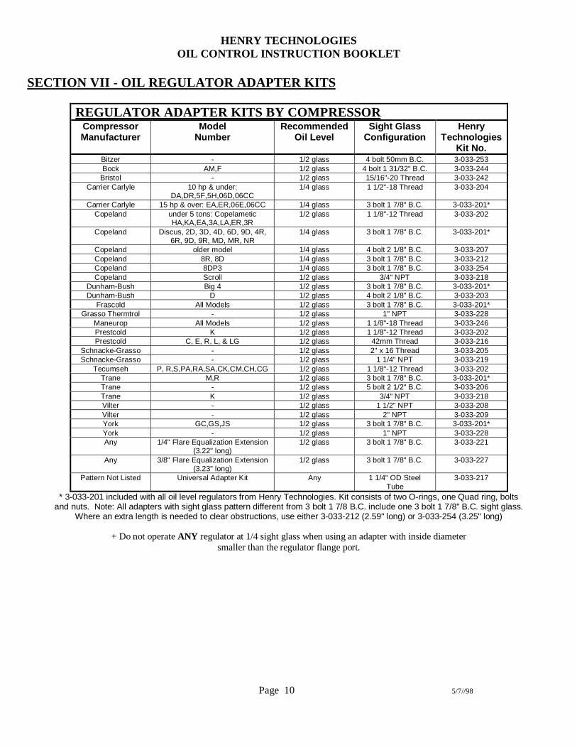
SECTION VII - OIL REGULATOR ADAPTER KITS
REGULATOR ADAPTER KITS BY COMPRESSORCompressorManufacturer
ModelNumber
RecommendedOil Level
Sight GlassConfiguration
HenryTechnologies
Kit No.Bitzer - 1/2 glass 4 bolt 50mm B.C. 3-033-253Bock AM,F 1/2 glass 4 bolt 1 31/32" B.C. 3-033-244
Bristol - 1/2 glass 15/16"-20 Thread 3-033-242Carrier Carlyle 10 hp & under:
DA,DR,5F,5H,06D,06CC1/4 glass 1 1/2"-18 Thread 3-033-204
Carrier Carlyle 15 hp & over: EA,ER,06E,06CC 1/4 glass 3 bolt 1 7/8" B.C. 3-033-201*Copeland under 5 tons: Copelametic
HA,KA,EA,3A,LA,ER,3R1/2 glass 1 1/8"-12 Thread 3-033-202
Copeland Discus, 2D, 3D, 4D, 6D, 9D, 4R,6R, 9D, 9R, MD, MR, NR
1/4 glass 3 bolt 1 7/8" B.C. 3-033-201*
Copeland older model 1/4 glass 4 bolt 2 1/8" B.C. 3-033-207Copeland 8R, 8D 1/4 glass 3 bolt 1 7/8" B.C. 3-033-212Copeland 8DP3 1/4 glass 3 bolt 1 7/8" B.C. 3-033-254Copeland Scroll 1/2 glass 3/4" NPT 3-033-218
Dunham-Bush Big 4 1/2 glass 3 bolt 1 7/8" B.C. 3-033-201*Dunham-Bush D 1/2 glass 4 bolt 2 1/8" B.C. 3-033-203
Frascold All Models 1/2 glass 3 bolt 1 7/8" B.C. 3-033-201*Grasso Thermtrol - 1/2 glass 1" NPT 3-033-228
Maneurop All Models 1/2 glass 1 1/8"-18 Thread 3-033-246Prestcold K 1/2 glass 1 1/8"-12 Thread 3-033-202Prestcold C, E, R, L, & LG 1/2 glass 42mm Thread 3-033-216
Schnacke-Grasso - 1/2 glass 2" x 16 Thread 3-033-205Schnacke-Grasso - 1/2 glass 1 1/4" NPT 3-033-219
Tecumseh P, R,S,PA,RA,SA,CK,CM,CH,CG 1/2 glass 1 1/8"-12 Thread 3-033-202Trane M,R 1/2 glass 3 bolt 1 7/8" B.C. 3-033-201*Trane - 1/2 glass 5 bolt 2 1/2" B.C. 3-033-206Trane K 1/2 glass 3/4" NPT 3-033-218Vilter - 1/2 glass 1 1/2" NPT 3-033-208Vilter - 1/2 glass 2" NPT 3-033-209York GC,GS,JS 1/2 glass 3 bolt 1 7/8" B.C. 3-033-201*York - 1/2 glass 1" NPT 3-033-228Any 1/4" Flare Equalization Extension
(3.22" long)1/2 glass 3 bolt 1 7/8" B.C. 3-033-221
Any 3/8" Flare Equalization Extension(3.23" long)
1/2 glass 3 bolt 1 7/8" B.C. 3-033-227
Pattern Not Listed Universal Adapter Kit Any 1 1/4" OD SteelTube
3-033-217
* 3-033-201 included with all oil level regulators from Henry Technologies. Kit consists of two O-rings, one Quad ring, boltsand nuts. Note: All adapters with sight glass pattern different from 3 bolt 1 7/8 B.C. include one 3 bolt 1 7/8" B.C. sight glass.
Where an extra length is needed to clear obstructions, use either 3-033-212 (2.59" long) or 3-033-254 (3.25" long)
+ Do not operate ANY regulator at 1/4 sight glass when using an adapter with inside diametersmaller than the regulator flange port.

HENRY TECHNOLOGIESOIL CONTROL INSTRUCTION BOOKLET
Page 11 5/7//98
SECTION VIII – SERVICE/TROUBLESHOOTINGVery little service needs to be performed on oil control systems. Most or all service necessary will stem from debris in the oil,
especially in systems using polyolester (POE) oil. Filters in POE oil systems should be changed at least three times in the first threemonths of operation and at least once a year after start-up.
Many of the oil separators have cleanable/replaceable floats. Drain the oil from the separator through the 1/8” NPTF fitting onthe bottom of the float assembly plate on S-1900, S-5700, and S-5200 series separators. If the float is clogged shut, there will beexcessive amounts of oil in the separator, be prepared to catch a few gallons of oil on larger separators. When cleaning a float, insure thatall debris is removed from the area around the float, including the magnet that picks up steel filings. Back feed oil through the 3/8” flareoil return fitting with a hand oil pump to push any debris from inside the float seat. Newer S-5200 series Helical Oil Separators include ascreen tube in the sump area, which catches some debris before it enters the float sump. This screen tube should be removed and cleanedand reinserted when replacing the float assembly. Always replace the header plate gasket every time the float is removed. Re-torque allbolts evenly to 35 foot pounds. The separator must be precharged with oil after replacing the float. Oil may be back-fed into theseparator through the 3/8” flare oil return fitting with a hand pump. This will take about 120 psig of pressure, but a hand pump should beable to push the float open. Once the oil is in, the float valve will keep the oil in the separator.
Troubleshooting oil systems involves physically checking a few key components in the system: the oil return line from theseparator, the oil reservoir level, the oil regulator levels, the oil line sight glass, and the amount of oil that can be drained from the oilseparator.
The first thing to check is the oil return line. Feeling the oil return line and seeing how often it gets hot is the main way to tell ifthe separator is working properly. It is easier if an oil line sight glass is installed, mainly because if the oil line is hot you don’t reallyknow if it is oil or hot gas causing it to be hot. If the oil line cycles between hot and cold at least a few times per hour, the separator ismost likely working properly. The float tends to open and feed a few ounces of oil at a time and shut until the oil builds back up. If theoil return is cycling, there is no need to drain the separator, look at the other oil components.
Always check the oil reservoir level during a service call. Oil levels in the reservoir will normally vary during periods of varyingloads: compressors shut-down, hot-gas defrost, etc. This is normal, however if the level is consistently low or high, the oil system shouldbe checked thoroughly.
Compressor oil levels can be deceiving. It is some times hard to tell if the regulator is feeding oil or if oil is coming down thesuction line. If the reservoir has too much pressure, often times this pressure will force oil out of the regulator and show a low level, eventhough there is excessive oil in the compressor. Many times the best way to check the oil in the compressor is to shut off the oil feedingto the regulator and wait a few minutes. If oil is pushed out of the regulator or trapped in the motor cavity on semi-hermetics, thecompressor will over-fill.
The oil line sight glass is a good way to see how the separator is working. Look for movement in the glass. If the separator isnot feeding on single or low-pressure systems, the sight glass will have little or no movement and normally will appear empty, dependingon how it is piped. If the separator is feeding, the sight glass will show a rush of oil and foam past the glass.
To check the oil level in the separator if the separator has a drain, shut off the oil return line to prevent further feeding, pumpdown the system, shut off the system, evacuate the separator, and drain the oil from the bottom. The separator should hold prechargeamount plus or minus a few ounces during operation. By looking at the amount above or below the precharge, any problem with theseparator or float can be determined by this amount
The Helical Oil Separators (S-5100 and S-5200 series) are not likely to fail due to debris as other types of oil separators,however, the float valve can be clogged or damaged. When a Helical Oil Separator is installed, the system load is not changed, and theseparator worked fine for a while, if oil return from the separator becomes a problem, the float or other component is most likely thecause.
Note that there is no way to clean or repair an all welded oil separator. If it is determined that the float is clogged or otherwisemalfunctioning, the entire oil separator must be replaced.
When the refrigerant and/or oil types are changed in a system, there is the potential for leaks around o-ring seals. Mostelastomers absorb oil and refrigerant and may swell or shrink when exposed to a new oil or refrigerant. In these cases, replace the o-ringsand seals in the system as needed.

HENRY TECHNOLOGIESOIL CONTROL INSTRUCTION BOOKLET
Page 12 5/7//98
SYSTEMSS-SINGLE
L-LOWPRESSURE
SEPARATOROIL RETURN LINE
OIL RESERVOIRLEVEL
COMPRESSOR OILLEVELS
OIL LINE SIGHTGLASS
AMOUNT OF OILDRAINED FROM
SEPARATOR
PROBABLE CAUSES CORRECTIVEACTION
S, L CYCLES STEADY STEADY CYCLES PRECHARGEAMOUNT
SYSTEM WORKINGPROPERLY
NONE
S, L CYCLES ALWAYS LOW STEADY OR LOW CYCLES PRECHARGEAMOUNT
SYSTEM WORKINGPROPERLY, NOTENOUGH OIL
ADD OIL TO SYSTEM
L CYCLES ALWAYS LOW HIGH CYCLES PRECHARGEAMOUNT
OIL LEVEL SET TOOHIGH ONREGULATORS,POSSIBLEREGULATORLEAKING
LOWER REGULATORLEVELS, REPLACEREGULATOR IFNECESSARY
L CYCLES ALWAYS LOW HIGH CYCLES PRECHARGEAMOUNT
EXCESSIVERESERVOIRPRESSURE
CHECK RESERVOIRPRESSURE VS.SUCTION
S, L CYCLES ALWAYS HIGH STEADY OR HIGH CYCLES PRECHARGEAMOUNT
SYSTEM WORKINGPROPERLY, TOOMUCH OIL
REMOVE OIL FROMSYSTEM
L CYCLES ALWAYS HIGH LOW CYCLES PRECHARGEAMOUNT
OIL LEVEL SET TOOLOW ONREGULATORS
RAISE REGULATORLEVELS
L CYCLES ALWAYS HIGH LOW CYCLES PRECHARGEAMOUNT
INSUFFICIENTRESERVOIRPRESSURE
CHECK RESERVOIRPRESSURE VS.SUCTION, REPLACERESERVOIRPRESSURE VALVE
L CYCLES ALWAYS HIGH LOW CYCLES PRECHARGEAMOUNT
OIL STRAINERS ORREGULATORSCLOGGED
REPLACESTRAINERS ORREGULATORS
S, L ALWAYS HOT ORVERY FREQUENTLY
HOT
ANY ANY STREAM OF OIL EXCESSIVE OIL SYSTEM OILLOGGED,SEPARATORFEEDING MORE OILTHANCOMPRESSORSNORMALLY SHOULDEMIT
REMOVE EXCESSOIL FROM SYSTEM
S, L ALWAYS HOT ORVERY FREQUENTLY
HOT
ANY ANY HOT GAS OR FOAM EMPTY SEPARATOR FLOATSTUCK OPEN ORLEAKING
OLD SYSTEM-REMOVE FLOAT ANDCLEAN/REPLACENEW SYSTEM-INSURE OILSEPARATOR WASPRECHARGED
S, L ALWAYS HOT ORVERY FREQUENTLY
HOT
ANY ANY HOT GAS OR FOAM EMPTY SEPARATOR TOOSMALLEXCESSIVEVELOCITY CAUSINGFLOAT TO BOUNCE
REVIEW SEPARATORSIZING
S, L ALWAYS ROOMTEMP
EMPTY EMPTY EMPTY EXCESSIVE OIL SEPARATOR FLOATCLOGGED
REMOVE ANDCLEAN/REPLACEFLOAT
S, L ALWAYS ROOMTEMP
EMPTY EMPTY EMPTY EXCESSIVE OIL OIL FILTERCLOGGED
REPLACE FILTER
S, L ALWAYS ROOMTEMP
EMPTY EMPTY EMPTY PRECHARGE OREMPTY
SEPARATOR TOOLARGE, INEFFICIENTSEPARATION
DOUBLE-CHECKSIZING
S, L COLD, SWEATING ORFROSTING AT START
UP
ANY ANY LIQUIDREFRIGERANT & OIL
DO NOT DRAINSEPARATOR
LIQUIDREFRIGERANT BACKFEEDING ORMIGRATING TOSEPARATOR DURINGCOMPRESSOR OFFCYCLE
INSTALL DISCHARGECHECK VALVEBETWEENSEPARATOR &CONDENSER
S, L COLD, SWEATING ORFROSTING WHILESYSTEM RUNNING
ANY ANY LIQUIDREFRIGERANT & OIL
DO NOT DRAINSEPARATOR
LIQUIDREFRIGERANTCONDENSING INSEPARATOR FROMLOSS OF SUPER-HEAT, COLDAMBIENT, POSSIBLESEPARATOR TOOLARGE
INSULATESEPARATOR, ADDHEAT BAND REVIEWSEPARATOR SIZING
HENRY TECHNOLOGIESOIL CONTROL INSTRUCTION BOOKLET
Page 13 5/7//98
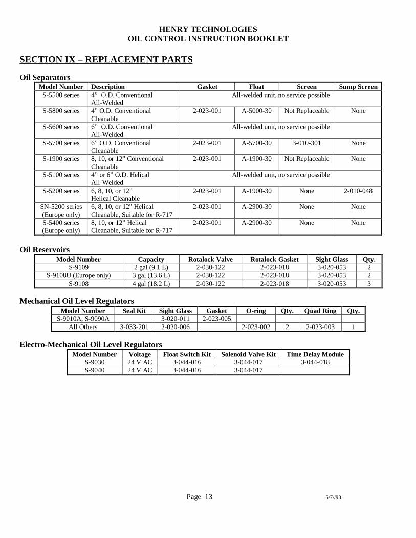
SECTION IX – REPLACEMENT PARTS
Oil SeparatorsModel Number Description Gasket Float Screen Sump Screen
S-5500 series 4” O.D. ConventionalAll-Welded
All-welded unit, no service possible
S-5800 series 4” O.D. ConventionalCleanable
2-023-001 A-5000-30 Not Replaceable None
S-5600 series 6” O.D. ConventionalAll-Welded
All-welded unit, no service possible
S-5700 series 6” O.D. ConventionalCleanable
2-023-001 A-5700-30 3-010-301 None
S-1900 series 8, 10, or 12” ConventionalCleanable
2-023-001 A-1900-30 Not Replaceable None
S-5100 series 4” or 6” O.D. HelicalAll-Welded
All-welded unit, no service possible
S-5200 series 6, 8, 10, or 12”Helical Cleanable
2-023-001 A-1900-30 None 2-010-048
SN-5200 series(Europe only)
6, 8, 10, or 12” HelicalCleanable, Suitable for R-717
2-023-001 A-2900-30 None None
S-5400 series(Europe only)
8, 10, or 12” HelicalCleanable, Suitable for R-717
2-023-001 A-2900-30 None None
Oil ReservoirsModel Number Capacity Rotalock Valve Rotalock Gasket Sight Glass Qty.
S-9109 2 gal (9.1 L) 2-030-122 2-023-018 3-020-053 2S-9108U (Europe only) 3 gal (13.6 L) 2-030-122 2-023-018 3-020-053 2
S-9108 4 gal (18.2 L) 2-030-122 2-023-018 3-020-053 3
Mechanical Oil Level RegulatorsModel Number Seal Kit Sight Glass Gasket O-ring Qty. Quad Ring Qty.
S-9010A, S-9090A 3-020-011 2-023-005All Others 3-033-201 2-020-006 2-023-002 2 2-023-003 1
Electro-Mechanical Oil Level RegulatorsModel Number Voltage Float Switch Kit Solenoid Valve Kit Time Delay Module
S-9030 24 V AC 3-044-016 3-044-017 3-044-018S-9040 24 V AC 3-044-016 3-044-017