of the european union - digital tachograph 2018-502.pdf · 2018-07-12 · european union. this...
TRANSCRIPT

II Non-legislative acts
REGULATIONS
★ Commission Implementing Regulation (EU) 2018/502 of 28 February 2018 amending Implementing Regulation (EU) 2016/799 laying down the requirements for the construction, testing, installation, operation and repair of tachographs and their components ( 1 ) . . . . . . . . . . . 1
Acts whose titles are printed in light type are those relating to day-to-day management of agricultural matters, and are generally valid for a limited period.
The titles of all other acts are printed in bold type and preceded by an asterisk.
L 85
Volume 61
28 March 2018 Legislation
( 1 ) Text with EEA relevance.
Official Journal of the European Union
EN
English edition
Contents


II
(Non-legislative acts)
REGULATIONS
COMMISSION IMPLEMENTING REGULATION (EU) 2018/502
of 28 February 2018
amending Implementing Regulation (EU) 2016/799 laying down the requirements for the construction, testing, installation, operation and repair of tachographs and their components
(Text with EEA relevance)
THE EUROPEAN COMMISSION,
Having regard to the Treaty on the Functioning of the European Union,
Having regard to Regulation (EU) No 165/2014 of the European Parliament and of the Council of 4 February 2014 on tachographs in road transport ( 1 ), and in particular Articles 11 and 12(7) thereof,
Whereas:
(1) Regulation (EU) No 165/2014 has introduced smart tachographs, second-generation digital tachographs which include a connection to the global navigation satellite system (‘GNSS’) facility, a remote early detection communication facility, and an optional interface with intelligent transport systems.
(2) The technical requirements for the construction, testing, installation, operation and repair of tachographs and their components are set out in Commission Implementing Regulation (EU) 2016/799 ( 2 ).
(3) In accordance with Articles 8, 9 and 10 of Regulation (EU) No 165/2014, tachographs installed in vehicles registered for the first time on or after 15 June 2019 shall be smart tachographs. Implementing Regulation (EU) 2016/799 must therefore be amended so that the technical provisions laid down therein apply from that date.
(4) In order to comply with Article 8 of Regulation (EU) No 165/2014, which establishes that the position of the vehicle must be recorded every 3 hours of accumulated driving time, Implementing Regulation (EU) 2016/799 should be amended to enable information on the position of the vehicle to be stored with a 3-hour frequency, using a metric that cannot be reset, and to avoid confusion with ‘continuous driving time’, which is a metric with a different function.
(5) The vehicle unit may be a single unit or several units distributed in the vehicle. The GNSS and the Dedicated Short Range Communication (‘DSRC’) facilities could therefore be internal or external to the vehicle unit main body. When they are external, it should be possible that both facilities and the main body of the vehicle unit can be type- approved as components, in order to adapt the smart tachograph type-approval process to the needs of the market.
(6) The rules on the storage of time conflict events and time adjustments must be modified, in order to distinguish between the automatic time adjustments that are triggered following a possible tampering attempt or malfunctioning of the tachograph, and the time adjustments that are due to other reasons such as maintenance.
(7) The data identifiers should be able to distinguish between data downloaded from a smart tachograph and data downloaded from a tachograph of a previous generation.
EN 28.3.2018 Official Journal of the European Union L 85/1
( 1 ) OJ L 60, 28.2.2014, p. 1. ( 2 ) Commission Implementing Regulation (EU) 2016/799 of 18 March 2016 implementing Regulation (EU) No 165/2014 of the
European Parliament and of the Council laying down the requirements for the construction, testing, installation, operation and repair of tachographs and their components (OJ L 139, 26.5.2016, p. 1).

(8) The validity period of the company card must be extended from 2 to 5 years, in order to align it with the validity period of the driver card.
(9) The description of certain faults and events, the validation of the entries of places where daily work period begins and/or end, the use of the driver consent for Intelligent Transport System (‘ITS’) interface regarding data transmitted by the vehicle unit through the vehicle network and other technical issues should be better defined.
(10) In order to ensure that the certification of tachograph seals is up to date, they need to be adjusted to the new standard on the security of the mechanical seals used on tachographs.
(11) This Regulation concerns the construction, testing, installation and operation of systems which are also comprised of radio equipment regulated by Directive 2014/53/EU of the European Parliament and of the Council ( 1 ). This Directive regulates the placement on the market and putting into service of electronic and electrical equipment using radio waves for communication and/or radiodetermination at a horizontal level, with particular respect to electrical safety, compatibility with other systems, access to radio spectrum, access to emergency services and/or any additional delegated provisions. In order to guarantee the efficient use of radio spectrum, to prevent harmful radio interferences, to ensure the safety and the electromagnetic compatibility of the radio equipment and to allow any other specific delegated requirements, this Regulation should be without prejudice to that Directive.
(12) Implementing Regulation (EU) 2016/799 should therefore be amended.
(13) The measures provided for in this Regulation are in accordance with the opinion of the Committee referred to in Article 42(3) of Regulation (EU) No 165/2014,
HAS ADOPTED THIS REGULATION:
Article 1
Implementing Regulation (EU) 2016/799 is amended as follows:
(1) Article 1 is amended as follows:
(a) the second and third paragraphs are replaced by the following:
‘2. The construction, testing, installation, inspection, operation and repair of smart tachographs and their components, shall comply with the technical requirements set out in Annex IC to this Regulation.
3. Tachographs other than smart tachographs shall continue, as regards construction, testing, installation, inspection, operation and repair, to comply with the requirements of either Annex I to Regulation (EU) No 165/2014 or Annex IB to Council Regulation (EEC) No 3821/85 (*), as applicable;
___________ (*) Council Regulation (EEC) No 3821/85 of 20 December 1985 on recording equipment in road transport
(OJ L 370, 31.12.1985, p. 8).’;
(b) the following paragraph 5 is added:
‘5. This Regulation shall be without prejudice to Directive 2014/53/EU of the European Parliament and of the Council (*).
___________ (*) Directive 2014/53/EU of the European Parliament and of the Council of 16 April 2014 on the harmonisation
of the laws of the Member States relating to the making available on the market of radio equipment and repealing Directive 1999/5/EC (OJ L 153, 22.5.2014, p. 62).’;
(2) Article 2 is amended as follows:
(a) definition (3) is replaced by the following:
‘(3) “information folder” means the complete folder, in electronic or paper form, containing all the information supplied by the manufacturer or its agent to the type-approval authority for the purpose of the type-approval of a tachograph or a component thereof, including the certificates referred to in Article 12(3) of Regulation (EU) No 165/2014, the performance of the tests defined in Annex IC to this Regulation, as well as drawings, photographs, and other relevant documents;’;
EN L 85/2 Official Journal of the European Union 28.3.2018
( 1 ) Directive 2014/53/EU of the European Parliament and of the Council of 16 April 2014 on the harmonisation of the laws of the Member States relating to the making available on the market of radio equipment and repealing Directive 1999/5/EC (OJ L 153, 22.5.2014, p. 62).

(b) definition (7) is replaced by the following:
‘(7) “smart tachograph” or “second generation tachograph” means a digital tachograph complying with Articles 8, 9 and 10 of Regulation (EU) No 165/2014 as well as with Annex IC to this Regulation;’;
(c) definition (8) is replaced by the following:
‘(8) “tachograph component” means any of the following elements: the vehicle unit, the motion sensor, the record sheet, the external GNSS facility and the external remote early detection facility;’;
(d) the following definition (10) is added:
‘(10) “vehicle unit” means the tachograph excluding the motion sensor and the cables connecting the motion sensor.
It may be a single unit or several units distributed in the vehicle and includes a processing unit, a data memory, a time measurement function, two smart card interface devices for driver and co-driver, a printer, a display, connectors and facilities for entering the user’s inputs, a GNSS receiver and a remote communication facility.
The vehicle unit may be composed of the following components subject to type-approval:
— vehicle unit, as a single component (including GNSS receiver and remote communication facility),
— vehicle unit main body (including remote communication facility), and external GNSS facility,
— vehicle unit main body (including GNSS receiver), and external remote communication facility,
— vehicle unit main body, external GNSS facility, and external remote communication facility.
If the vehicle unit is composed of several units distributed in the vehicle, the vehicle unit main body is the unit containing the processing unit, the data memory, and the time measurement function.
“vehicle unit (VU)” is used for “vehicle unit” or “vehicle unit main body” ’;
(3) in Article 6, the third paragraph is replaced by the following:
‘However, Annex IC shall apply from 15 June 2019 with the exception of Appendix 16 which shall apply from 2 March 2016.’;
(4) Annex IC is amended in accordance with Annex I to this Regulation;
(5) Annex II is amended in accordance with Annex II to this Regulation.
Article 2
Entry into force
This Regulation shall enter into force on the twentieth day following that of its publication in the Official Journal of the European Union.
This Regulation shall be binding in its entirety and directly applicable in all Member States.
Done at Brussels, 28 February 2018.
For the Commission The President
Jean-Claude JUNCKER
EN 28.3.2018 Official Journal of the European Union L 85/3

ANNEX I
Annex IC to Regulation (EU) 2016/799 is amended as follows:
(1) the Table of Contents is amended as follows:
(a) point 3.12.5 is replaced by the following:
‘3.12.5. Places and positions where daily work periods begin, end and/or where 3 hours accumulated driving time is reached’;
(b) point 4.5.3.2.16 is replaced by the following:
‘4.5.3.2.16 Three hours accumulated driving places data’;
(c) point 4.5.4.2.14 is replaced by the following:
‘4.5.4.2.14 Three hours accumulated driving places data’;
(d) point 6.2 is replaced by the following:
‘6.2 Check of new or repaired components’;
(2) point 1 is amended as follows:
(a) definition (ll) is replaced by the following:
‘(ll) “remote communication facility” or “remote early detection facility” means:
the equipment of the vehicle unit which is used to perform targeted roadside checks;’;
(b) definition (tt) is replaced by the following:
‘(tt) “time adjustment” means:
an adjustment of current time; this adjustment can be automatic at regular intervals, using the time provided by the GNSS receiver as a reference, or performed in calibration mode;’;
(c) the first dash of definition (yy) is replaced by the following:
‘— installed and used only in M1 and N1 type vehicles (as defined in Annex II to Directive 2007/46/EC of the European Parliament and of the Council (*), as last amended),’;
(d) a new definition (fff) is added:
‘(fff) “accumulated driving time” means:
a value representing the total accumulated number of minutes of driving of a particular vehicle.
The accumulated driving time value is a free running count of all minutes regarded as DRIVING by the monitoring of driving activities function of the recording equipment, and is only used for triggering the recording of the vehicle position, every time a multiple of three hours of accumulated driving is reached. The accumulation is started at the recording equipment activation. It is not affected by any other condition, like out of scope or ferry/train crossing.
The accumulated driving time value is not intended to be displayed, printed, or downloaded;’;
EN L 85/4 Official Journal of the European Union 28.3.2018

(3) in point 2.3, the last indent of paragraph (13) is replaced by the following:
‘— the vehicle units have a normal operations validity period of 15 years, starting with the vehicle unit certificates effective date, but vehicle units can be used for additional 3 months, for data downloading only.’;
(4) in point 2.4, the first paragraph is replaced by the following:
‘The system security aims at protecting the data memory in such a way as to prevent unauthorised access to and manipulation of the data and detecting any such attempts, protecting the integrity and authenticity of data exchanged between the motion sensor and the vehicle unit, protecting the integrity and authenticity of data exchanged between the recording equipment and the tachograph cards, protecting the integrity and authenticity of data exchanged between the vehicle unit and the external GNSS facility, if any, protecting the confidentiality, integrity and authenticity of data exchanged through the remote early detection communication for control purposes, and verifying the integrity and authenticity of data downloaded.’;
(5) in point 3.2, the second dash of paragraph (27) is replaced by the following:
‘— positions where the accumulated driving time reaches a multiple of three hours;’;
(6) in point 3.4, paragraph (49) is replaced by the following:
‘(49) The first change of activity to BREAK/REST or AVAILABILITY arising within 120 seconds of the automatic change to WORK due to the vehicle stop shall be assumed to have happened at the time of vehicle stop (therefore possibly cancelling the change to WORK).’;
(7) in point 3.6.1, paragraph (59) is replaced by the following:
‘(59) The driver shall then enter the current place of the vehicle, which shall be considered as a temporary entry.
Under the following conditions temporary entry made at last card withdrawal is validated (i.e. shall not be overwritten anymore):
— entry of a place where the current daily work period begins during manual entry according to requirement (61);
— the next entry of a place where the current daily work period begins if the card holder doesn’t enter any place where the work period begins or ended during the manual entry according to requirement (61).
Under the following conditions temporary entry made at last card withdrawal is overwritten and the new value is validated:
— the next entry of a place where the current daily work period ends if the card holder doesn’t enter any place where the work period begins or ended during the manual input according to requirement (61)’;
(8) in point 3.6.2, the sixth and seventh dashes are replaced by the following:
‘— a place where a previous daily work period ended, associated to the relevant time (thus overwriting and validating the entry made at the last card withdrawal),
— a place where the current daily work period begins, associated to the relevant time (thus validating a temporary entry made at last card withdrawal).’;
EN 28.3.2018 Official Journal of the European Union L 85/5

(9) point 3.9.15 is replaced by the following:
‘3.9.15 “Time conflict” event
(86) This event shall be triggered, while not in calibration mode, when the VU detects a discrepancy of more than 1 minute between the time of the vehicle unit’s time measurement function and the time originating from the GNSS receiver. This event is recorded together with the internal clock value of the vehicle unit and comes together with an automatic time adjustment. After a time conflict event has been triggered, the VU will not generate other time conflict events for the next 12 hours. This event shall not be triggered in cases where no valid GNSS signal was detectable by the GNSS receiver for 30 days or more.’;
(10) in point 3.9.17, the following dash is added:
‘— ITS interface fault (if applicable)’;
(11) point 3.10 is amended as follows:
(i) the text before the table in paragraph (89) is replaced by the following:
‘The recording equipment shall detect faults through self-tests and built-in-tests, according to the following table:’;
(ii) The following row is added to the table:
‘ITS interface (optional) Proper operation’
(12) the second dash of point 3.12 is replaced by the following:
‘— the average number of positions per day is defined as at least 6 positions where the daily work period begins, 6 positions when the accumulated driving time reaches a multiple of three hours, and 6 positions where the daily work period ends, so that “365 days” include at least 6570 positions,’;
(13) point 3.12.5 is amended as follows:
(a) the heading and paragraph (108) are replaced by the following:
‘3.12.5. Places and positions where daily work periods begin, end and/or where 3 hours accumulated driving time is reached
(108) The recording equipment shall record and store in its data memory:
— places and positions where the driver and/or co-driver begins his daily work period;
— positions where the accumulated driving time reaches a multiple of three hours;
— places and positions where the driver and/or the co-driver ends his daily work period.’;
(b) the fourth dash of paragraph (110) is replaced by the following:
‘— The type of entry (begin, end or 3 hours accumulated driving time),’;
EN L 85/6 Official Journal of the European Union 28.3.2018
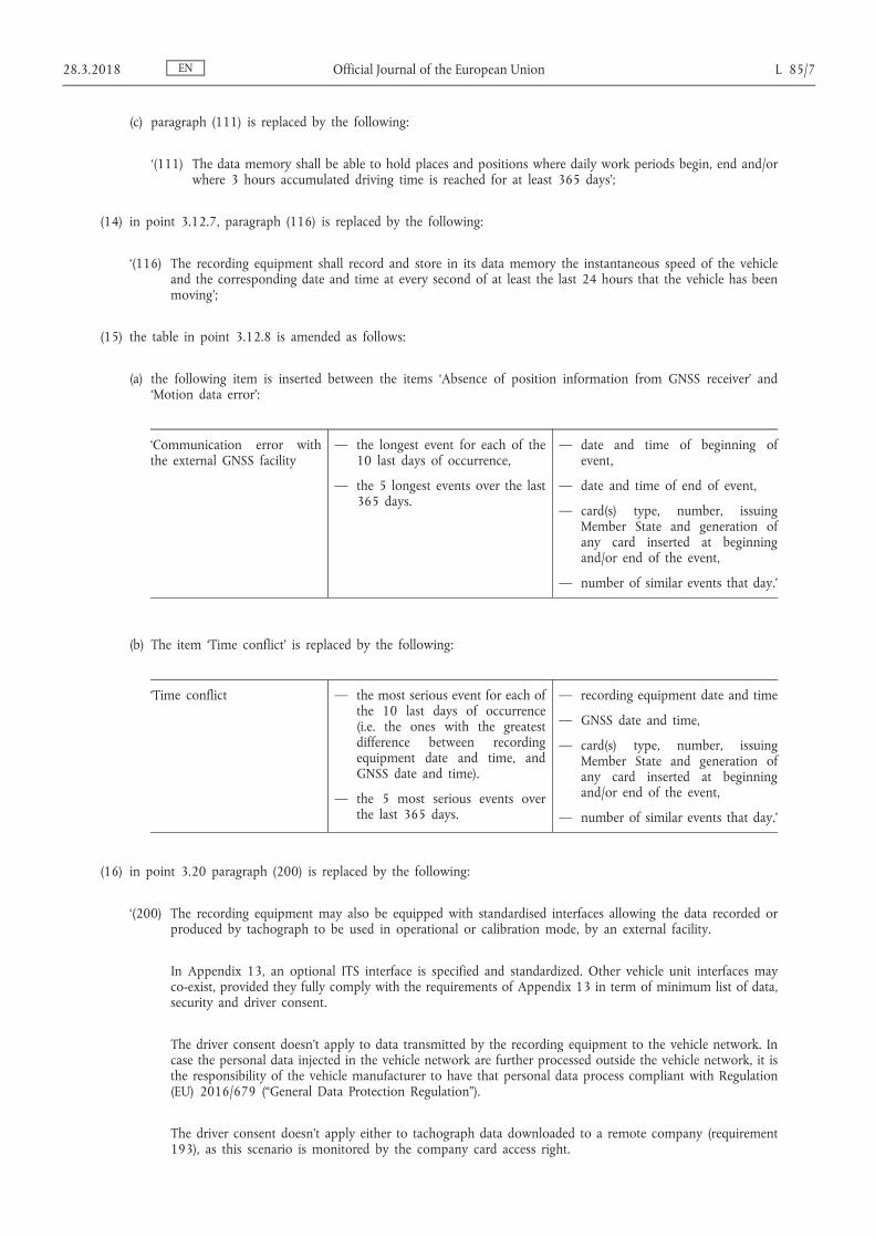
(c) paragraph (111) is replaced by the following:
‘(111) The data memory shall be able to hold places and positions where daily work periods begin, end and/or where 3 hours accumulated driving time is reached for at least 365 days’;
(14) in point 3.12.7, paragraph (116) is replaced by the following:
‘(116) The recording equipment shall record and store in its data memory the instantaneous speed of the vehicle and the corresponding date and time at every second of at least the last 24 hours that the vehicle has been moving’;
(15) the table in point 3.12.8 is amended as follows:
(a) the following item is inserted between the items ‘Absence of position information from GNSS receiver’ and ‘Motion data error’:
‘Communication error with the external GNSS facility
— the longest event for each of the 10 last days of occurrence,
— the 5 longest events over the last 365 days.
— date and time of beginning of event,
— date and time of end of event,
— card(s) type, number, issuing Member State and generation of any card inserted at beginning and/or end of the event,
— number of similar events that day.’
(b) The item ‘Time conflict’ is replaced by the following:
‘Time conflict — the most serious event for each of the 10 last days of occurrence (i.e. the ones with the greatest difference between recording equipment date and time, and GNSS date and time).
— the 5 most serious events over the last 365 days.
— recording equipment date and time
— GNSS date and time,
— card(s) type, number, issuing Member State and generation of any card inserted at beginning and/or end of the event,
— number of similar events that day.’
(16) in point 3.20 paragraph (200) is replaced by the following:
‘(200) The recording equipment may also be equipped with standardised interfaces allowing the data recorded or produced by tachograph to be used in operational or calibration mode, by an external facility.
In Appendix 13, an optional ITS interface is specified and standardized. Other vehicle unit interfaces may co-exist, provided they fully comply with the requirements of Appendix 13 in term of minimum list of data, security and driver consent.
The driver consent doesn’t apply to data transmitted by the recording equipment to the vehicle network. In case the personal data injected in the vehicle network are further processed outside the vehicle network, it is the responsibility of the vehicle manufacturer to have that personal data process compliant with Regulation (EU) 2016/679 (“General Data Protection Regulation”).
The driver consent doesn’t apply either to tachograph data downloaded to a remote company (requirement 193), as this scenario is monitored by the company card access right.
EN 28.3.2018 Official Journal of the European Union L 85/7

The following requirements apply to ITS data made available through that interface:
— these data are a set of selected existing data from the tachograph data dictionary (Appendix 1),
— a subset of these selected data are marked “personal data”,
— the subset of “personal data” is only available if the verifiable consent of the driver, accepting his personal data can leave the vehicle network, is enabled,
— At any moment, the driver consent can be enabled or disabled through commands in the menu, provided the driver card is inserted,
— the set and subset of data will be broadcasted via Bluetooth wireless protocol in the radius of the vehicle cab, with a refresh rate of 1 minute,
— the pairing of the external device with the ITS interface will be protected by a dedicated and random PIN of at least 4 digits, recorded in and available through the display of each vehicle unit,
— in any circumstances, the presence of the ITS interface cannot disturb or affect the correct functioning and the security of the vehicle unit.
Other data may also be output in addition to the set of selected existing data, considered as the minimum list, provided they cannot be considered as personal data.
The recording equipment shall have the capacity to communicate the driver consent status to other platforms in the vehicle network.
When the ignition of the vehicle is ON, these data shall be permanently broadcasted.’;
(17) in point 3.23, paragraph (211) is replaced by the following:
‘(211) The time setting of the VU internal clock shall be automatically re-adjusted every 12 hours. When this re-adjustment is not possible because the GNSS signal is not available, the time setting shall be done as soon as the VU can access a valid time provided by GNSS receiver, according to the vehicle ignition conditions. The time reference for the automatic time setting of the VU internal clock shall be derived from the GNSS receiver.’;
(18) in point 3.26, paragraphs (225) and (226) are replaced by the following:
‘(225) A descriptive plaque shall be affixed to each separate component of the recording equipment and shall show the following details:
— name and address of the manufacturer,
— manufacturer's part number and year of manufacture,
— serial number,
— type-approval mark.
EN L 85/8 Official Journal of the European Union 28.3.2018

(226) When physical space is not sufficient to show all above mentioned details, the descriptive plaque shall show at least: the manufacturer's name or logo and the part number.’;
(19) in point 4.1, the drawing corresponding to the front and reverse of the driver card is replaced by the following:
(20) in point 4.5.3.1.8, the first dash in paragraph (263) is replaced by the following:
‘— Card fault (where this card is the subject of the fault),’;
(21) in point 4.5.3.2.8, the first dash in paragraph (288) is replaced by the following:
‘— Card fault (where this card is the subject of the fault),’;
(22) point 4.5.3.2.16 is replaced by the following:
‘4.5.3.2.16 Three hours accumulated driving places data
(305) The driver card shall be able to store the following data related to the position of the vehicle where the accumulated driving time reaches a multiple of three hours:
— the date and time when the accumulated driving time reaches a multiple of three hours,
— the position of the vehicle,
— the GNSS accuracy, date and time when the position was determined,
— the vehicle odometer value.
(306) The driver card shall be able to store at least 252 such records.’;
(23) point 4.5.4.2.14 is replaced by the following:
‘4.5.4.2.14 Three hours accumulated driving places data
(353) The workshop card shall be able to store the following data related to the position of the vehicle where the accumulated driving time reaches a multiple of three hours:
— the date and time when the accumulated driving time reaches a multiple of three hours,
EN 28.3.2018 Official Journal of the European Union L 85/9
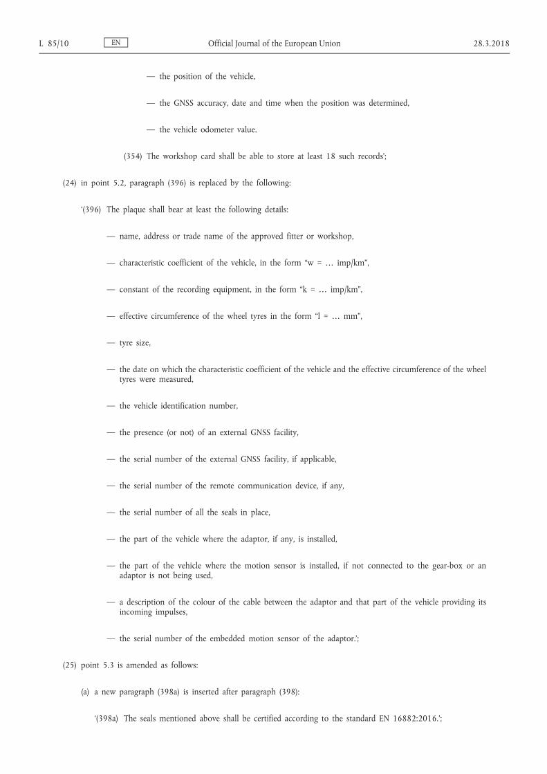
— the position of the vehicle,
— the GNSS accuracy, date and time when the position was determined,
— the vehicle odometer value.
(354) The workshop card shall be able to store at least 18 such records’;
(24) in point 5.2, paragraph (396) is replaced by the following:
‘(396) The plaque shall bear at least the following details:
— name, address or trade name of the approved fitter or workshop,
— characteristic coefficient of the vehicle, in the form “w = … imp/km”,
— constant of the recording equipment, in the form “k = … imp/km”,
— effective circumference of the wheel tyres in the form “l = … mm”,
— tyre size,
— the date on which the characteristic coefficient of the vehicle and the effective circumference of the wheel tyres were measured,
— the vehicle identification number,
— the presence (or not) of an external GNSS facility,
— the serial number of the external GNSS facility, if applicable,
— the serial number of the remote communication device, if any,
— the serial number of all the seals in place,
— the part of the vehicle where the adaptor, if any, is installed,
— the part of the vehicle where the motion sensor is installed, if not connected to the gear-box or an adaptor is not being used,
— a description of the colour of the cable between the adaptor and that part of the vehicle providing its incoming impulses,
— the serial number of the embedded motion sensor of the adaptor.’;
(25) point 5.3 is amended as follows:
(a) a new paragraph (398a) is inserted after paragraph (398):
‘(398a) The seals mentioned above shall be certified according to the standard EN 16882:2016.’;
EN L 85/10 Official Journal of the European Union 28.3.2018

(b) in paragraph (401), the second sub-paragraph is replaced by the following:
‘This unique identification number is defined as: MMNNNNNNNN by non-removable marking, with MM as unique manufacturer identification (database registration to be managed by EC) and NNNNNNNN seal alpha- numeric number, unique in the manufacturer domain.’;
(c) paragraph (403) is replaced by the following:
‘(403) Seals manufacturers shall be registered in a dedicated database when they get a seal model certified according to EN 16882:2016 and shall make their identification seals numbers public through a procedure to be established by the European Commission.’;
(d) paragraph (404) is replaced by the following:
‘(404) Approved workshops and vehicle manufacturers shall, in the frame of Regulation (EU) No 165/2014, only use seals certified according to EN 16882:2016 from those of the seals manufacturers listed in the database mentioned above.’;
(26) point 6.2 is replaced by the following:
‘6.2. Check of new or repaired components
(407) Every individual device, whether new or repaired, shall be checked in respect of its proper operation and the accuracy of its reading and recordings, within the limits laid down in Chapter 3.2.1, 3.2.2, 3.2.3 and 3.3’;
(27) in point 6.3, paragraph (408) is replaced by the following:
‘(408) When being fitted to a vehicle, the whole installation (including the recording equipment) shall comply with the provisions relating to maximum tolerances laid down in Chapter 3.2.1, 3.2.2, 3.2.3 and 3.3. The whole installation shall be sealed in accordance with Chapter 5.3 and it shall include a calibration.’;
(28) point 8.1 is amended as follows
(a) in point 8.1, the introduction text before paragraph (425) is replaced by the following:
‘For the purpose of this chapter, the words “recording equipment” mean “recording equipment or its components”. No type approval is required for the cable(s) linking the motion sensor to the VU, the external GNSS facility to the VU or the external remote communication facility to the VU. The paper, for use by the recording equipment, shall be considered as a component of the recording equipment.
Any manufacturer may ask for type approval of recording equipment component(s) with any other recording equipment component(s), provided each component complies with the requirements of this annex. Alternately, manufacturers may also ask for type approval of recording equipment.
As described in definition (10) in Article 2 of this Regulation, vehicle units have variants in components assembly. Whatever the vehicle unit components assembly, the external antenna and (if applicable) the antenna splitter connected to the GNSS receiver or to the remote communication facility are not part of the vehicle unit type approval.
EN 28.3.2018 Official Journal of the European Union L 85/11

Nevertheless, manufacturers having obtained type approval for recording equipment shall maintain a publicly available list of compatible antennas and splitters with each type approved vehicle unit, external GNSS facility and external remote communication facility.’;
(b) paragraph (427) is replaced by the following:
‘(427) Member States type approval authorities will not grant a type approval certificate as long as they do not hold:
— a security certificate (if requested by this Annex),
— a functional certificate,
— and an interoperability certificate (if requested by this Annex)
for the recording equipment or the tachograph card, subject of the request for type approval.’;
(29) Appendix 1 is amended as follows:
(a) the Table of Content is amended as follows:
(i) point 2.63 is replaced by the following:
‘2.63 Reserved for future use’;
(ii) point 2.78 is replaced by the following:
‘2.78 GNSSAccumulatedDriving’;
(iii) point 2.79 is replaced by the following:
‘2.79 GNSSAccumulatedDrivingRecord’;
(iv) point 2.111 is replaced by the following:
‘2.111 NoOfGNSSADRecords’;
(v) point 2.160 is replaced by the following:
‘2.160 Reserved for future use’;
(vi) point 2.203 is replaced by the following:
‘2.203 VuGNSSADRecord’;
(vii) point 2.204 is replaced by the following:
‘2.204 VuGNSSADRecordArray’;
(viii) point 2.230 is replaced by the following:
‘2.230 Reserved for future use’;
(ix) point 2.231 is replaced by the following:
‘2.231 Reserved for future use’;
EN L 85/12 Official Journal of the European Union 28.3.2018

(b) in point 2, the following text is added before point 2.1:
‘For card data types used for Generation 1 and Generation 2 applications, the size specified in this Appendix is the one for Generation 2 application. The size for Generation 1 application is supposed to be already known by the reader. The Annex IC requirement numbers related to such data types cover both Generation 1 and Generation 2 applications.’;
(c) point 2.19 is replaced by the following:
‘2.19. CardEventData
Generation 1:
Information, stored in a driver or workshop card, related to the events associated with the card holder (Annex IC requirements 260 and 318).
CardEventData is a sequence, ordered by ascending value of EventFaultType, of cardEventRecords (except security breach attempts related records which are gathered in the last set of the sequence).
cardEventRecords is a set of event records of a given event type (or category for security breach attempts events).
Generation 2:
Information, stored in a driver or workshop card, related to the events associated with the card holder (Annex IC requirements 285 and 341).
CardEventData is a sequence, ordered by ascending value of EventFaultType, of cardEventRecords (except security breach attempts related records which are gathered in the last set of the sequence).
cardEventRecords is a set of event records of a given event type (or category for security breach attempts events).’
(d) point 2.30 is replaced by the following:
‘2.30. CardRenewalIndex
A card renewal index (definition i)).
Value assignment: (see this Annex chapter 7).
“0” First issue.
Order for increase: “0, …, 9, A, …, Z” ’;
EN 28.3.2018 Official Journal of the European Union L 85/13

(e) in point 2.61, the text after the heading Generation 2 is replaced by the following:
In addition to generation 1 the following data elements are used:
noOfGNSSADRecords is the number of GNSS accumulated driving records the card can store.
noOfSpecificConditionRecords is the number of specific condition records the card can store.
noOfCardVehicleUnitRecords is the number of vehicle units used records the card can store.’;
(f) point 2.63 is replaced by the following:
‘2.63. Reserved for future use’;
(g) in point 2.67, the text under the heading ‘Generation 2’ is replaced by the following:
‘The same values as in generation 1 are used with the following additions:
Note 1: The generation 2 values for the Plaque, Adapter and the External GNSS connection as well as the generation 1 values for the Vehicle Unit and Motion Sensor may be used in SealRecord, i.e. if applicable.
Note 2: In the CardHolderAuthorisation (CHA) field of a generation 2 certificate, the values (1), (2), and (6) are to be interpreted as indicating a certificate for Mutual Authentication for the respective equipment type. For indicating the respective certificate for creating a digital signature, the values (17), (18) or (19) must be used.’;
EN L 85/14 Official Journal of the European Union 28.3.2018

(h) in point 2.70, the text under the heading ‘Generation 2’ is replaced by the following:
‘Generation 2:
General events, No further details, Insertion of a non valid card, Card conflict, Time overlap, Driving without an appropriate card, Card insertion while driving, Last card session not correctly closed, Over speeding, Power supply interruption, Motion data error, Vehicle Motion Conflict, Time conflict (GNSS versus VU internal clock), Communication error with the remote communication facility, Absence of position information from GNSS receiver, Communication error with the external GNSS facility, RFU,
Vehicle unit related security breach attempt events, No further details, Motion sensor authentication failure, Tachograph card authentication failure, Unauthorised change of motion sensor, Card data input integrity error Stored user data integrity error, Internal data transfer error, Unauthorised case opening, Hardware sabotage, Tamper detection of GNSS, External GNSS facility authentication failure, External GNSS facility certificate expired, RFU,
Sensor related security breach attempt events, No further details, Authentication failure, Stored data integrity error, Internal data transfer error, Unauthorised case opening, Hardware sabotage, RFU,
Recording equipment faults, No further details, VU internal fault, Printer fault, Display fault, Downloading fault, Sensor fault, Internal GNSS receiver, External GNSS facility, Remote communication facility, ITS interface, RFU,
Card faults, No further details, RFU,
RFU,
Manufacturer specific.’;
EN 28.3.2018 Official Journal of the European Union L 85/15

(i) Point 2.71 is replaced by the following:
‘2.71. ExtendedSealIdentifier
Generation 2:
The extended seal identifier uniquely identifies a seal (Annex IC requirement 401).
manufacturerCode is a code of the manufacturer of the seal.
sealIdentifier is an identifier for the seal which is unique for the manufacturer.’;
(j) points 2.78 and 2.79 are replaced by the following:
‘2.78 GNSSAccumulatedDriving
Generation 2:
Information, stored in a driver or workshop card, related to the GNSS position of the vehicle if the accumulated driving time reaches a multiple of three hours (Annex IC requirement 306 and 354).
gnssADPointerNewestRecord is the index of the last updated GNSS accumulated driving record.
Value assignment is the number corresponding to the numerator of the GNSS accumulated driving record, beginning with '0' for the first occurrence of the GNSS accumulated driving record in the structure.
gnssAccumulatedDrivingRecords is the set of records containing the date and time the accumulated driving reaches a multiple of three hours and information on the position of the vehicle.
2.79. GNSSAccumulatedDrivingRecord
Generation 2:
Information, stored in a driver or workshop card, related to the GNSS position of the vehicle if the accumulated driving time reaches a multiple of three hours (Annex IC requirement 305 and 353)
timeStamp is the date and time when the accumulated driving time reaches a multiple of three hours.
gnssPlaceRecord contains information related to the position of the vehicle.
vehicleOdometerValue is the odometer value when the accumulated driving time reaches a multiple of three hours.’;
EN L 85/16 Official Journal of the European Union 28.3.2018

(k) point 2.86 is replaced by the following:
‘2.86. KeyIdentifier
A unique identifier of a Public Key used to reference and select the key. It also identifies the holder of the key.
The first choice is suitable to reference the public key of a Vehicle Unit, of a tachograph card or of an external GNSS facility.
The second choice is suitable to reference the public key of a Vehicle Unit (in cases where the serial number of the Vehicle Unit cannot be known at certificate generation time).
The third choice is suitable to reference the public key of a Member State.’;
(l) point 2.92 is replaced by the following:
‘2.92. MAC
Generation 2:
A cryptographic check sum of 8, 12 or 16 bytes length corresponding to the cipher suites specified in Appendix 11.
(m) point 2.111 is replaced by the following:
‘2.111. NoOfGNSSADRecords
Generation 2:
Number of GNSS accumulated driving records a card can store.
Value assignment: see Appendix 2.’;
(n) in point 2.120, the value assignment ‘16H’ is replaced by the following:
‘ ’;
(o) point 2.160 is replaced by the following:
‘2.160. Reserved for future use’;
EN 28.3.2018 Official Journal of the European Union L 85/17

(p) point 2.162 is replaced by the following:
‘2.162. TimeReal
Code for a combined date and time field, where the date and time are expressed as seconds past 00h.00m.00s. on 1 January 1970 UTC.
Value assignment – Octet aligned: Number of seconds since midnight 1 January 1970 UTC.
The max. possible date/time is in the year 2106.’;
(q) point 2.179 is replaced by the following:
‘2.179 VuCardRecord
Generation 2:
Information, stored in a vehicle unit, about a tachograph card used (Annex IC requirement 132).
cardNumberAndGenerationInformation is the full card number and generation of the card used (data type 2.74).
cardExtendedSerialNumber as read from the file EF_ICC under the MF of the card.
cardStructureVersion as read from the file EF_Application_Identification under the DF_Tachograph_G2.
cardNumber as read from the file EF_Identification under the DF_Tachograph_G2.’;
(r) points 2.203 and 2.204 are replaced by the following:
‘2.203 VuGNSSADRecord
Generation 2:
Information, stored in a vehicle unit, related to the GNSS position of the vehicle if the accumulated driving time reaches a multiple of three hours (Annex IC requirement 108, 110).
timeStamp is the date and time when the accumulated driving time reaches a multiple of three hours.
cardNumberAndGenDriverSlot identifies the card including its generation which is inserted in the driver slot.
EN L 85/18 Official Journal of the European Union 28.3.2018
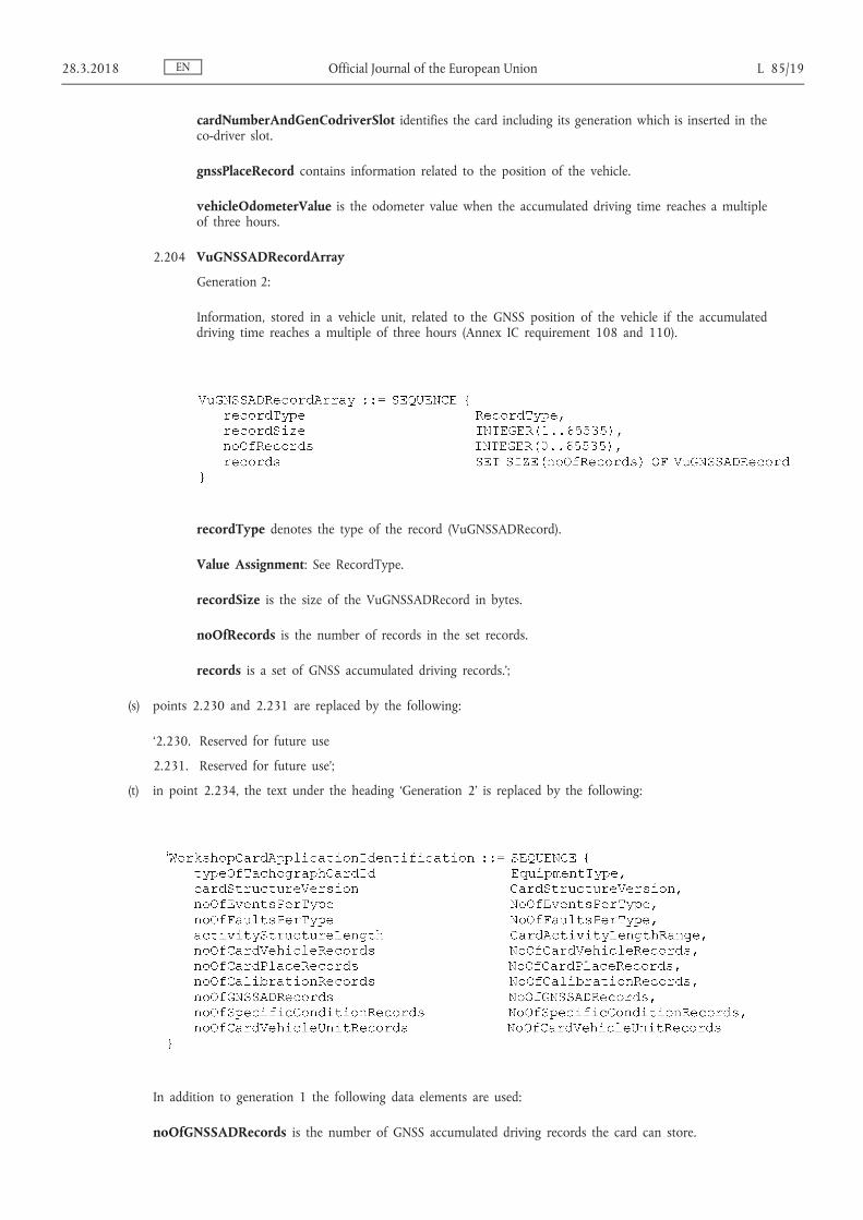
cardNumberAndGenCodriverSlot identifies the card including its generation which is inserted in the co-driver slot.
gnssPlaceRecord contains information related to the position of the vehicle.
vehicleOdometerValue is the odometer value when the accumulated driving time reaches a multiple of three hours.
2.204 VuGNSSADRecordArray
Generation 2:
Information, stored in a vehicle unit, related to the GNSS position of the vehicle if the accumulated driving time reaches a multiple of three hours (Annex IC requirement 108 and 110).
recordType denotes the type of the record (VuGNSSADRecord).
Value Assignment: See RecordType.
recordSize is the size of the VuGNSSADRecord in bytes.
noOfRecords is the number of records in the set records.
records is a set of GNSS accumulated driving records.’;
(s) points 2.230 and 2.231 are replaced by the following:
‘2.230. Reserved for future use
2.231. Reserved for future use’;
(t) in point 2.234, the text under the heading ‘Generation 2’ is replaced by the following:
In addition to generation 1 the following data elements are used:
noOfGNSSADRecords is the number of GNSS accumulated driving records the card can store.
EN 28.3.2018 Official Journal of the European Union L 85/19
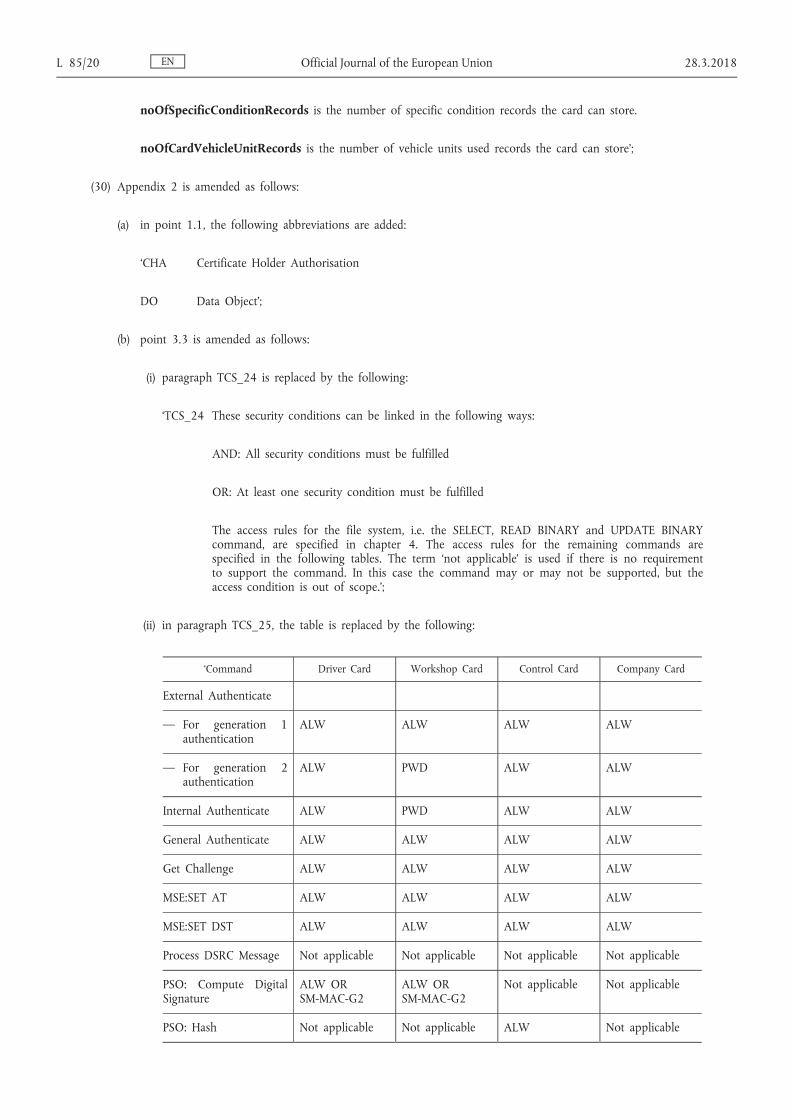
noOfSpecificConditionRecords is the number of specific condition records the card can store.
noOfCardVehicleUnitRecords is the number of vehicle units used records the card can store’;
(30) Appendix 2 is amended as follows:
(a) in point 1.1, the following abbreviations are added:
‘CHA Certificate Holder Authorisation
DO Data Object’;
(b) point 3.3 is amended as follows:
(i) paragraph TCS_24 is replaced by the following:
‘TCS_24 These security conditions can be linked in the following ways:
AND: All security conditions must be fulfilled
OR: At least one security condition must be fulfilled
The access rules for the file system, i.e. the SELECT, READ BINARY and UPDATE BINARY command, are specified in chapter 4. The access rules for the remaining commands are specified in the following tables. The term ‘not applicable’ is used if there is no requirement to support the command. In this case the command may or may not be supported, but the access condition is out of scope.’;
(ii) in paragraph TCS_25, the table is replaced by the following:
‘Command Driver Card Workshop Card Control Card Company Card
External Authenticate
— For generation 1 authentication
ALW ALW ALW ALW
— For generation 2 authentication
ALW PWD ALW ALW
Internal Authenticate ALW PWD ALW ALW
General Authenticate ALW ALW ALW ALW
Get Challenge ALW ALW ALW ALW
MSE:SET AT ALW ALW ALW ALW
MSE:SET DST ALW ALW ALW ALW
Process DSRC Message Not applicable Not applicable Not applicable Not applicable
PSO: Compute Digital Signature
ALW OR SM-MAC-G2
ALW OR SM-MAC-G2
Not applicable Not applicable
PSO: Hash Not applicable Not applicable ALW Not applicable
EN L 85/20 Official Journal of the European Union 28.3.2018

Command Driver Card Workshop Card Control Card Company Card
PERFORM HASH of FILE
ALW OR SM-MAC-G2
ALW OR SM-MAC-G2
Not applicable Not applicable
PSO: Verify Certificate ALW ALW ALW ALW
PSO: Verify Digital Signature
Not applicable Not applicable ALW Not applicable
Verify Not applicable ALW Not applicable Not applicable’
(iii) in paragraph TCS_26, the table is replaced by the following:
‘Command Driver Card Workshop Card Control Card Company Card
External Authenticate
— For generation 1 authentication
Not applicable Not applicable Not applicable Not applicable
— For generation 2 authentication
ALW PWD ALW ALW
Internal Authenticate Not applicable Not applicable Not applicable Not applicable
General Authenticate ALW ALW ALW ALW
Get Challenge ALW ALW ALW ALW
MSE:SET AT ALW ALW ALW ALW
MSE:SET DST ALW ALW ALW ALW
Process DSRC Message Not applicable ALW ALW Not applicable
PSO: Compute Digital Signature
ALW OR SM-MAC-G2
ALW OR SM-MAC-G2
Not applicable Not applicable
PSO: Hash Not applicable Not applicable ALW Not applicable
PERFORM HASH of FILE
ALW OR SM-MAC-G2
ALW OR SM-MAC-G2
Not applicable Not applicable
PSO: Verify Certificate ALW ALW ALW ALW
PSO: Verify Digital Signature
Not applicable Not applicable ALW Not applicable
Verify Not applicable ALW Not applicable Not applicable’
EN 28.3.2018 Official Journal of the European Union L 85/21
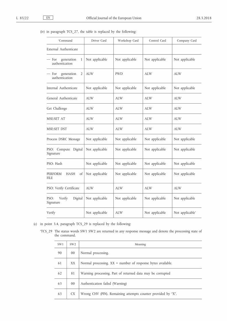
(iv) in paragraph TCS_27, the table is replaced by the following:
‘Command Driver Card Workshop Card Control Card Company Card
External Authenticate
— For generation 1 authentication
Not applicable Not applicable Not applicable Not applicable
— For generation 2 authentication
ALW PWD ALW ALW
Internal Authenticate Not applicable Not applicable Not applicable Not applicable
General Authenticate ALW ALW ALW ALW
Get Challenge ALW ALW ALW ALW
MSE:SET AT ALW ALW ALW ALW
MSE:SET DST ALW ALW ALW ALW
Process DSRC Message Not applicable Not applicable Not applicable Not applicable
PSO: Compute Digital Signature
Not applicable Not applicable Not applicable Not applicable
PSO: Hash Not applicable Not applicable Not applicable Not applicable
PERFORM HASH of FILE
Not applicable Not applicable Not applicable Not applicable
PSO: Verify Certificate ALW ALW ALW ALW
PSO: Verify Digital Signature
Not applicable Not applicable Not applicable Not applicable
Verify Not applicable ALW Not applicable Not applicable’
(c) in point 3.4, paragraph TCS_29 is replaced by the following:
‘TCS_29 The status words SW1 SW2 are returned in any response message and denote the processing state of the command.
SW1 SW2 Meaning
90 00 Normal processing.
61 XX Normal processing. XX = number of response bytes available.
62 81 Warning processing. Part of returned data may be corrupted
63 00 Authentication failed (Warning)
63 CX Wrong CHV (PIN). Remaining attempts counter provided by “X”.
EN L 85/22 Official Journal of the European Union 28.3.2018
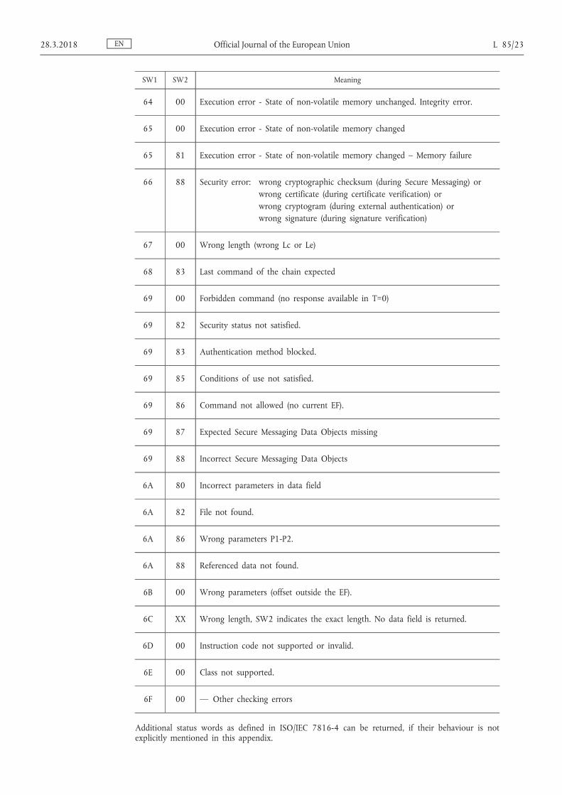
SW1 SW2 Meaning
64 00 Execution error - State of non-volatile memory unchanged. Integrity error.
65 00 Execution error - State of non-volatile memory changed
65 81 Execution error - State of non-volatile memory changed – Memory failure
66 88 Security error: wrong cryptographic checksum (during Secure Messaging) or wrong certificate (during certificate verification) or wrong cryptogram (during external authentication) or wrong signature (during signature verification)
67 00 Wrong length (wrong Lc or Le)
68 83 Last command of the chain expected
69 00 Forbidden command (no response available in T=0)
69 82 Security status not satisfied.
69 83 Authentication method blocked.
69 85 Conditions of use not satisfied.
69 86 Command not allowed (no current EF).
69 87 Expected Secure Messaging Data Objects missing
69 88 Incorrect Secure Messaging Data Objects
6A 80 Incorrect parameters in data field
6A 82 File not found.
6A 86 Wrong parameters P1-P2.
6A 88 Referenced data not found.
6B 00 Wrong parameters (offset outside the EF).
6C XX Wrong length, SW2 indicates the exact length. No data field is returned.
6D 00 Instruction code not supported or invalid.
6E 00 Class not supported.
6F 00 — Other checking errors
Additional status words as defined in ISO/IEC 7816-4 can be returned, if their behaviour is not explicitly mentioned in this appendix.
EN 28.3.2018 Official Journal of the European Union L 85/23

For example the following status words can be optionally returned:
6881: Logical channel not supported
6882: Secure messaging not supported’;
(d) in point 3.5.1.1, the last indent in paragraph TCS_38 is replaced by the following:
‘— If the selected application is considered to be corrupted (integrity error is detected within the file attributes), the processing state returned is “6400” or “6500”.’;
(e) in point 3.5.1.2, the last indent in paragraph TCS_41 is replaced by the following:
‘— If the selected file is considered to be corrupted (integrity error is detected within the file attributes), the processing state returned is “6400” or “6500”.’;
(f) in point 3.5.2.1, the sixth indent in paragraph TCS_43 is replaced by the following:
‘— If an integrity error is detected within the file attributes, the card shall consider the file as corrupted and unrecoverable, the processing state returned is “6400” or “6500”.’;
(g) point 3.5.2.1.1 is amended as follows:
(i) in paragraph TCS_45, the table is replaced by the following:
‘Byte Length Value Description
#1 1 “81h” T PV : Tag for plain value data
#2 L “NNh” or “81 NNh”
L PV : length of returned data (=original Le). L is 2 bytes if L PV >127 bytes.
#(2+L) - #(1+L+NN) NN “XX..XXh” Plain Data value
#(2+L+NN) 1 “99h” Tag for Processing Status (SW1-SW2) – optional for generation 1 secure messaging
#(3+L+NN) 1 “02h” Length of Processing Status – optional for generation 1 secure messaging
#(4+L+NN) - #(5+L+NN) 2 “XX XXh” Processing Status of the unprotected response APDU – optional for generation 1 secure messaging
#(6+L+NN) 1 “8Eh” TCC: Tag for cryptographic checksum
#(7+L+NN) 1 “XXh” LCC: Length of following cryptographic checksum “04h” for Generation 1 secure messaging (see Appendix 11 Part A) “08h”, “0Ch” or “10h” depending on AES key length for Generation 2 secure messaging (see Appendix 11 Part B)
EN L 85/24 Official Journal of the European Union 28.3.2018
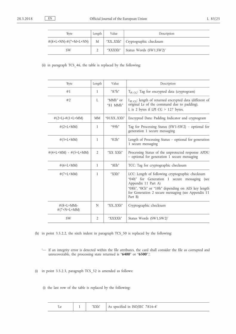
‘Byte Length Value Description
#(8+L+NN)-#(7+M+L+NN) M “XX..XXh” Cryptographic checksum
SW 2 “XXXXh” Status Words (SW1,SW2)’
(ii) in paragraph TCS_46, the table is replaced by the following:
‘Byte Length Value Description
#1 1 “87h” T PI CG : Tag for encrypted data (cryptogram)
#2 L “MMh” or “81 MMh”
L PI CG : length of returned encrypted data (different of original Le of the command due to padding). L is 2 bytes if LPI CG > 127 bytes.
#(2+L)-#(1+L+MM) MM “01XX..XXh” Encrypted Data: Padding Indicator and cryptogram
#(2+L+MM) 1 “99h” Tag for Processing Status (SW1-SW2) – optional for generation 1 secure messaging
#(3+L+MM) 1 “02h” Length of Processing Status – optional for generation 1 secure messaging
#(4+L+MM) - #(5+L+MM) 2 “XX XXh” Processing Status of the unprotected response APDU – optional for generation 1 secure messaging
#(6+L+MM) 1 “8Eh” TCC: Tag for cryptographic checksum
#(7+L+MM) 1 “XXh” LCC: Length of following cryptographic checksum “04h” for Generation 1 secure messaging (see Appendix 11 Part A) “08h”, “0Ch” or “10h” depending on AES key length for Generation 2 secure messaging (see Appendix 11 Part B)
#(8+L+MM)- #(7+N+L+MM)
N “XX..XXh” Cryptographic checksum
SW 2 “XXXXh” Status Words (SW1,SW2)’
(h) in point 3.5.2.2, the sixth indent in paragraph TCS_50 is replaced by the following:
‘— If an integrity error is detected within the file attributes, the card shall consider the file as corrupted and unrecoverable, the processing state returned is “6400” or “6500”.’;
(i) in point 3.5.2.3, paragraph TCS_52 is amended as follows:
(i) the last row of the table is replaced by the following:
‘Le 1 'XXh' As specified in ISO/IEC 7816-4’
EN 28.3.2018 Official Journal of the European Union L 85/25
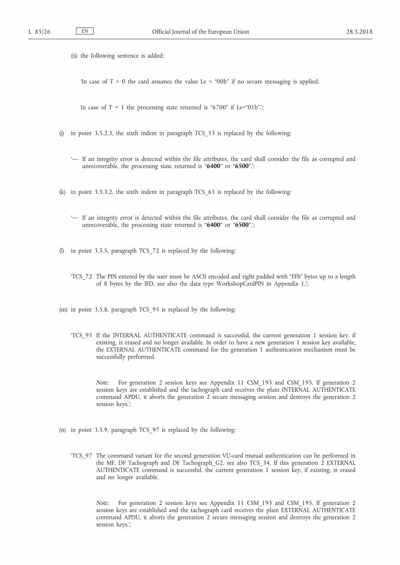
(ii) the following sentence is added:
‘In case of T = 0 the card assumes the value Le = “00h” if no secure messaging is applied.
In case of T = 1 the processing state returned is “6700” if Le=“01h”.’;
(j) in point 3.5.2.3, the sixth indent in paragraph TCS_53 is replaced by the following:
‘— If an integrity error is detected within the file attributes, the card shall consider the file as corrupted and unrecoverable, the processing state returned is “6400” or “6500”.’;
(k) in point 3.5.3.2, the sixth indent in paragraph TCS_63 is replaced by the following:
‘— If an integrity error is detected within the file attributes, the card shall consider the file as corrupted and unrecoverable, the processing state returned is “6400” or “6500”.’;
(l) in point 3.5.5, paragraph TCS_72 is replaced by the following:
‘TCS_72 The PIN entered by the user must be ASCII encoded and right padded with “FFh” bytes up to a length of 8 bytes by the IFD, see also the data type WorkshopCardPIN in Appendix 1.’;
(m) in point 3.5.8, paragraph TCS_95 is replaced by the following:
‘TCS_95 If the INTERNAL AUTHENTICATE command is successful, the current generation 1 session key, if existing, is erased and no longer available. In order to have a new generation 1 session key available, the EXTERNAL AUTHENTICATE command for the generation 1 authentication mechanism must be successfully performed.
Note: For generation 2 session keys see Appendix 11 CSM_193 and CSM_195. If generation 2 session keys are established and the tachograph card receives the plain INTERNAL AUTHENTICATE command APDU, it aborts the generation 2 secure messaging session and destroys the generation 2 session keys.’;
(n) in point 3.5.9, paragraph TCS_97 is replaced by the following:
‘TCS_97 The command variant for the second generation VU-card mutual authentication can be performed in the MF, DF Tachograph and DF Tachograph_G2, see also TCS_34. If this generation 2 EXTERNAL AUTHENTICATE command is successful, the current generation 1 session key, if existing, is erased and no longer available.
Note: For generation 2 session keys see Appendix 11 CSM_193 and CSM_195. If generation 2 session keys are established and the tachograph card receives the plain EXTERNAL AUTHENTICATE command APDU, it aborts the generation 2 secure messaging session and destroys the generation 2 session keys.’;
EN L 85/26 Official Journal of the European Union 28.3.2018

(o) in point 3.5.10, the following row is added to the table in paragraph TCS_101:
‘5 + L + 1 1 “00h” As specified in ISO/IEC 7816-4’
(p) in point 3.5.11.2.3, the following paragraphs are added in paragraph TCS_114:
‘— If the currentAuthenticatedTime of the card is later than the Expiration Date of the selected public key, the processing state returned is “6A88”.
Note: In the case of a MSE: SET AT for VU Authentication command, the referenced key is a VU_MA public key. The card shall set the VU_MA public key for use, if available in its memory, which matches the Certificate Holder Reference (CHR) given in the command data field (the card can identify VU_MA public keys by means of the certificate's CHA field). A card shall return “6A 88” to this command in case only the VU_Sign public key or no public key of the Vehicle Unit is available. See the definition of the CHA field in Appendix 11 and of data type equipmentType in Appendix 1.
Similarly, in case an MSE: SET DST command referencing an EQT (i.e. a VU or a card) is sent to a control card, according to CSM_234 the referenced key is always an EQT_Sign key that has to be used for the verification of a digital signature. According to Figure 13 in Appendix 11, the control card will always have stored the relevant EQT_Sign public key. In some cases, the control card may have stored the corresponding EQT_MA public key. The control card shall always set the EQT_Sign public key for use when it receives an MSE: SET DST command.’;
(q) point 3.5.13 is amended as follows:
(i) paragraph TCS_121 is replaced by the following:
‘TCS_121 The temporarily stored hash of file value shall be deleted if a new hash of file value is computed by means of the PERFORM HASH of FILE command, if a DF is selected, and if the tachograph card is reset.’;
(ii) paragraph TCS_123 is replaced by the following:
‘TCS_123 The Tachograph Generation 2 application shall support the SHA-2 algorithm (SHA-256, SHA- 384 or SHA-512), specified by the cipher suite in Appendix 11 Part B for the card signature key Card_Sign.’;
(iii) the table in paragraph TCS_124 is replaced by the following:
‘Byte Length Value Description
CLA 1 “80h” CLA
INS 1 “2Ah” Perform Security Operation
P1 1 “90h” Tag: Hash
P2 1 “00h” Algorithm implicitly known For the Tachograph Generation 1 application: SHA-1 For the Tachograph Generation 2 application: SHA-2 algorithm (SHA-256, SHA-384 or SHA-512) defined by the cipher suite in Appendix 11 Part B for the card signature key Card_Sign’
EN 28.3.2018 Official Journal of the European Union L 85/27

(r) point 3.5.14 is amended as follows:
the text below the heading and until paragraph TCS_126 is replaced by the following:
'This command is used to compute the digital signature of previously computed hash code (see PERFORM HASH of FILE, §3.5.13).
Only the driver card and the workshop card are required to support this command in the DF Tachograph and DF Tachograph_G2.
Other types of tachograph cards may or may not implement this command. In case of the Generation 2 tachograph application, only the driver card and the workshop card have a generation 2 signature key, other cards are not able to successfully perform the command and terminate with a suitable error code.
The command may or may not be accessible in the MF. If the command is not accessible in the MF, it shall terminate with a suitable error code.
This command is compliant with ISO/IEC 7816-8. The use of this command is restricted regarding the related standard.';
(s) point 3.5.15 is amended as follows:
(i) the table in paragraph TCS_133 is replaced by the following:
‘Byte Length Value Description
CLA 1 “00h” CLA
INS 1 “2Ah” Perform Security Operation
P1 1 “00h”
P2 1 “A8h” Tag: data field contains DOs relevant for verification
Lc 1 “XXh” Length Lc of the subsequent data field
#6 1 “9Eh” Tag for Digital Signature
#7 or #7-#8
L “NNh” or “81 NNh”
Length of digital signature (L is 2 bytes if the digital signature is longer than 127 bytes): 128 bytes coded in accordance with Appendix 11 Part A for Tachograph Generation 1 application. Depending on the selected curve for Tachograph Generation 2 application (see Appendix 11 Part B).
#(7+L)-#(6+L+NN) NN “XX..XXh” Digital signature content’
(ii) the following indent is added to paragraph TCS_134:
‘— If the selected public key (used to verify the digital signature) has a CHA.LSB (CertificateHolderAuthorisation.equipmentType) that is not suitable for the digital signature verification according to Appendix 11, the processing state returned is “6985”.’;
EN L 85/28 Official Journal of the European Union 28.3.2018

(t) point 3.5.16 is amended as follows:
(i) in paragraph TCS_138, the following row is added to the table:
‘5 + L + 1 1 '00h' As specified in ISO/IEC 7816-4’
(ii) the following sub-paragraph is added to paragraph TCS_139:
‘— “6985” indicates that the 4-byte time stamp provided in the command data field is earlier than cardValidityBegin or later than cardExpiryDate.’;
(u) point 4.2.2 is amended as follows:
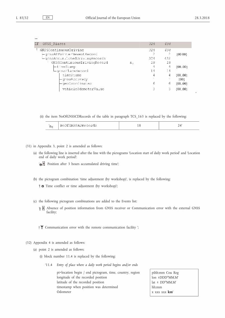
(i) in the data structure in paragraph TCS_154, the lines from DF Tachograph G2 to EF CardMA_Certificate, and the lines from EF GNSS_Places to the end of this paragraph are replaced by the following:
‘
’
EN 28.3.2018 Official Journal of the European Union L 85/29

(ii) in paragraph TCS_155, the item of the table is replaced by the following:
‘ 252 336’
(v) in point 4.3.1, the text corresponding to the abbreviation SC4 in paragraph TCS_156 is replaced by the following:
‘SC4 For the READ BINARY command with even INS byte:
(SM-C-MAC-G1 AND SM-R-ENC-MAC-G1) OR
(SM-C-MAC-G2 AND SM-R-ENC-MAC-G2)
For the READ BINARY command with odd INS byte (if supported): NEV’;
(w) point 4.3.2 is amended as follows:
(i) in the data structure in paragraph TCS_162, the lines from DF Tachograph G2 to EF CardMA_Certificate, the lines from EF Calibration to extendedSealIdentifier and the lines from EF GNSS_Places to vehicleOdometerValue are replaced by the following:
EN L 85/30 Official Journal of the European Union 28.3.2018

‘
EN 28.3.2018 Official Journal of the European Union L 85/31
’
(ii) the item NoOfGNSSCDRecords of the table in paragraph TCS_163 is replaced by the following:
‘ 18 24’
(31) in Appendix 3, point 2 is amended as follows:
(a) the following line is inserted after the line with the pictograms ‘Location start of daily work period’ and ‘Location end of daily work period’:
‘ Position after 3 hours accumulated driving time’;
(b) the pictogram combination ‘time adjustment (by workshop)’, is replaced by the following:
‘ Time conflict or time adjustment (by workshop)’;
(c) the following pictogram combinations are added to the Events list:
‘ Absence of position information from GNSS receiver or Communication error with the external GNSS facility;
Communication error with the remote communication facility ’;
(32) Appendix 4 is amended as follows:
(a) point 2 is amended as follows:
(i) block number 11.4 is replaced by the following:
‘11.4 Entry of place where a daily work period begins and/or ends
pi=location begin / end pictogram, time, country, region longitude of the recorded position latitude of the recorded position timestamp when position was determined Odometer
pihh:mm Cou Reg lon ±DDD o MM.M’ lat ± DD o MM.M’ hh:mm x xxx xxx km’
EN L 85/32 Official Journal of the European Union 28.3.2018
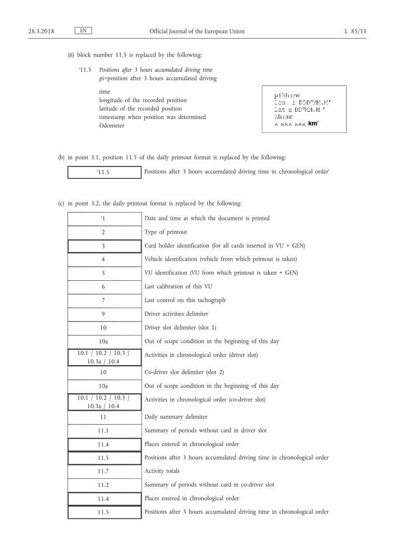
(ii) block number 11.5 is replaced by the following:
‘11.5 Positions after 3 hours accumulated driving time pi=position after 3 hours accumulated driving
time longitude of the recorded position latitude of the recorded position timestamp when position was determined Odometer
(b) in point 3.1, position 11.5 of the daily printout format is replaced by the following:
‘11.5 Positions after 3 hours accumulated driving time in chronological order’
(c) in point 3.2, the daily printout format is replaced by the following:
‘1 Date and time at which the document is printed
2 Type of printout
3 Card holder identification (for all cards inserted in VU + GEN)
4 Vehicle identification (vehicle from which printout is taken)
5 VU identification (VU from which printout is taken + GEN)
6 Last calibration of this VU
7 Last control on this tachograph
9 Driver activities delimiter
10 Driver slot delimiter (slot 1)
10a Out of scope condition in the beginning of this day
10.1 / 10.2 / 10.3 / 10.3a / 10.4
Activities in chronological order (driver slot)
10 Co-driver slot delimiter (slot 2)
10a Out of scope condition in the beginning of this day
10.1 / 10.2 / 10.3 / 10.3a / 10.4
Activities in chronological order (co-driver slot)
11 Daily summary delimiter
11.1 Summary of periods without card in driver slot
11.4 Places entered in chronological order
11.5 Positions after 3 hours accumulated driving time in chronological order
11.7 Activity totals
11.2 Summary of periods without card in co-driver slot
11.4 Places entered in chronological order
11.5 Positions after 3 hours accumulated driving time in chronological order
EN 28.3.2018 Official Journal of the European Union L 85/33

11.8 Activity totals
11.3 Summary of activities for a driver both slots included
11.4 Places entered by this driver in chronological order
11.5 Positions after 3 hours accumulated driving time in chronological order
11.9 Activity totals for this driver
13.1 Events faults delimiter
13.4 Event/Fault records (Last 5 events or faults stored or on-going in the VU)
22.1 Control place
22.2 Controller’s signature
22.3 From time (space available for a driver without a card to indicate
22.4 To time which periods are relevant to himself)
22.5 Driver's signature’
(d) in point 3.7, paragraph PRT_014 is replaced by the following:
‘PRT_014 The historic of inserted cards printout shall be in accordance with the following format:
1 Date and time at which the document is printed
2 Type of printout
3 Card holder identifications (of all cards inserted in the VU)
23 Most recent card inserted in the VU
23.1 Inserted cards (up to 88 records)
12.3 Faults delimiter’
(33) Appendix 7 is amended as follows:
(a) point 1.1 is replaced by the following:
‘1.1. Scope
Data may be downloaded to an ESM:
— from a Vehicle Unit by an Intelligent Dedicated Equipment (IDE) connected to the VU,
— from a tachograph card by an IDE fitted with a card interface device (IFD),
— from a tachograph card via a vehicle unit by an IDE connected to the VU.
To give the possibility to verify the authenticity and integrity of downloaded data stored on an ESM, data is downloaded with a signature appended in accordance with Appendix 11 Common Security Mechanisms. The source equipment (VU or card) identification and its security certificates (Member state and equipment) are also downloaded. The verifier of the data must possess independently a trusted European public key.
EN L 85/34 Official Journal of the European Union 28.3.2018

Data downloaded from a VU are signed using Appendix 11 Common Security Mechanisms Part B (Second-generation tachograph system), except when drivers' control is performed by a non EU control authority, using a first generation control card, in which case data are signed using Appendix 11 Common Security Mechanisms Part A (First-generation tachograph system), as requested by Appendix 15 Migration, requirement MIG_015.
This Appendix specifies therefore two types of data downloads from the VU:
— Generation 2 type of VU data download, providing the generation 2 data structure, signed using Appendix 11 Common Security Mechanisms Part B,
— Generation 1 type of VU data download, providing the generation 1 data structure, signed using Appendix 11 Common Security Mechanisms Part A.
Similarly, there are two types of data downloads from second generation driver cards inserted in a VU, as specified in paragraphs 3 and 4 of this Appendix.’;
(b) point 2.2.2 is amended as follows:
(i) the table is replaced by the following:
‘Message Structure Max 4 Bytes
Header Max 255 Bytes
Data 1 Byte
CheckSum
IDE -> <- VU FMT TGT SRC LEN SID DS_ / TRTP DATA CS
Start Communication Request 81 EE F0 81 E0
Positive Response Start Communication 80 F0 EE 03 C1 EA, 8F 9B
Start Diagnostic Session Request 80 EE F0 02 10 81 F1 Positive Response Start Diagnostic 80 F0 EE 02 50 81 31
Link Control Service Verify Baud Rate (stage 1)
9 600 Bd 80 EE F0 04 87 01,01,01 EC 19 200 Bd 80 EE F0 04 87 01,01,02 ED 38 400 Bd 80 EE F0 04 87 01,01,03 EE 57 600 Bd 80 EE F0 04 87 01,01,04 EF
115 200 Bd 80 EE F0 04 87 01,01,05 F0
Positive Response Verify Baud Rate 80 F0 EE 02 C7 01 28
Transition Baud Rate (stage 2) 80 EE F0 03 87 02,03 ED
Request Upload 80 EE F0 0A 35 00,00,00, 00,00,FF,FF,
FF,FF
99
Positive Response Request Upload 80 F0 EE 03 75 00,FF D5
Transfer Data Request Overview 80 EE F0 02 36 01 or 21 97 Activities 80 EE F0 06 36 02 or 22 Date CS Events & Faults 80 EE F0 02 36 03 or 23 Date 99 Detailed Speed 80 EE F0 02 36 04 or 24 Date 9A Technical Data 80 EE F0 02 36 05 or 25 Date 9B Card download 80 EE F0 02 36 06 Slot CS
EN 28.3.2018 Official Journal of the European Union L 85/35

Message Structure Max 4 Bytes
Header Max 255 Bytes
Data 1 Byte
CheckSum
IDE -> <- VU FMT TGT SRC LEN SID DS_ / TRTP DATA CS
Positive Response Transfer Data 80 F0 EE Len 76 TREP Data CS
Request Transfer Exit 80 EE F0 01 37 96
Positive Response Request Transfer Exit 80 F0 EE 01 77 D6
Stop Communication Request 80 EE F0 01 82 E1
Positive Response Stop Communication 80 F0 EE 01 C2 21
Acknowledge sub message 80 EE F0 Len 83 Data CS
Negative responses
General reject 80 F0 EE 03 7F Sid Req 10 CS
Service not supported 80 F0 EE 03 7F Sid Req 11 CS
Sub function not supported 80 F0 EE 03 7F Sid Req 12 CS
Incorrect Message Length 80 F0 EE 03 7F Sid Req 13 CS
Conditions not correct or Request sequence error
80 F0 EE 03 7F Sid Req 22 CS
Request out of range 80 F0 EE 03 7F Sid Req 31 CS
Upload not accepted 80 F0 EE 03 7F Sid Req 50 CS
Response pending 80 F0 EE 03 7F Sid Req 78 CS
Data not available 80 F0 EE 03 7F Sid Req FA CS’
(ii) the following indents are added to the Notes after the table:
‘— TRTP 21 to 25 are used for Generation 2 type of VU data download requests, TRTP 01 to 05 are used for Generation 1 type of VU data download requests, which can only be accepted by the VU in the frame of drivers' control performed by a non EU control authority, using a first generation control card,
— TRTP 11 to 19 and 31 to 39 are reserved for manufacturer specific download requests.’;
(c) point 2.2.2.9 is amended as follows:
(i) paragraph DDP_011 is replaced by the following:
‘DDP_011 The Transfer Data Request is sent by the IDE to specify to the VU the type of data that are to be downloaded. A one byte Transfer Request Parameter (TRTP) indicates the type of transfer.
There are six types of data transfer. For VU data download, two different TRTP values can be used for each transfer type:
Data transfer type TRTP value for generation 1 type of VU data download
TRTP value for generation 2 type of VU data download
Overview 01 21
Activities of a specified date 02 22
Events and faults 03 23
Detailed speed 04 24
Technical data 05 25
EN L 85/36 Official Journal of the European Union 28.3.2018
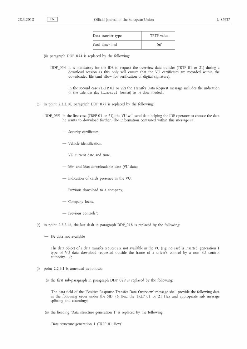
Data transfer type TRTP value
Card download 06’
(ii) paragraph DDP_054 is replaced by the following:
‘DDP_054 It is mandatory for the IDE to request the overview data transfer (TRTP 01 or 21) during a download session as this only will ensure that the VU certificates are recorded within the downloaded file (and allow for verification of digital signature).
In the second case (TRTP 02 or 22) the Transfer Data Request message includes the indication of the calendar day ( format) to be downloaded.’;
(d) in point 2.2.2.10, paragraph DDP_055 is replaced by the following:
‘DDP_055 In the first case (TREP 01 or 21), the VU will send data helping the IDE operator to choose the data he wants to download further. The information contained within this message is:
— Security certificates,
— Vehicle identification,
— VU current date and time,
— Min and Max downloadable date (VU data),
— Indication of cards presence in the VU,
— Previous download to a company,
— Company locks,
— Previous controls.’;
(e) in point 2.2.2.16, the last dash in paragraph DDP_018 is replaced by the following:
‘— FA data not available
The data object of a data transfer request are not available in the VU (e.g. no card is inserted, generation 1 type of VU data download requested outside the frame of a driver’s control by a non EU control authority…).’;
(f) point 2.2.6.1 is amended as follows:
(i) the first sub-paragraph in paragraph DDP_029 is replaced by the following:
‘The data field of the “Positive Response Transfer Data Overview” message shall provide the following data in the following order under the SID 76 Hex, the TREP 01 or 21 Hex and appropriate sub message splitting and counting:’;
(ii) the heading ‘Data structure generation 1’ is replaced by the following:
‘Data structure generation 1 (TREP 01 Hex)’;
EN 28.3.2018 Official Journal of the European Union L 85/37

(iii) the heading “Data structure generation 2” is replaced by the following:
‘Data structure generation 2 (TREP 21 Hex)’;
(g) point 2.2.6.2 is amended as follows:
(i) the first sub-paragraph in paragraph DDP_030 is replaced by the following:
‘The data field of the “Positive Response Transfer Data Activities” message shall provide the following data in the following order under the SID 76 Hex, the TREP 02 or 22 Hex and appropriate sub message splitting and counting:’;
(ii) the heading ‘Data structure generation 1’ is replaced by the following:
‘Data structure generation 1 (TREP 02 Hex)’;
(iii) the heading ‘Data structure generation 2’ is replaced by the following:
‘Data structure generation 2 (TREP 22 Hex)’;
(iv) the item VuGNSSCDRecordArray under the heading ‘Data structure generation 2 (TREP 22 Hex)’, is replaced by the following:
‘ GNSS positions of the vehicle when the accumulated driving time of the vehicle reaches a multiple of three hours. If the section is empty, an array header with noOfRecords = 0 is sent.’
(h) point 2.2.6.3 is amended as follows:
(i) the first sub-paragraph in paragraph DDP_031 is replaced by the following:
‘The data field of the “Positive Response Transfer Data Events and Faults” message shall provide the following data in the following order under the SID 76 Hex, the TREP 03 or 23 Hex and appropriate sub message splitting and counting:’;
(ii) the heading ‘Data structure generation 1’ is replaced by the following:
‘Data structure generation 1 (TREP 03 Hex)’;
(iii) the heading ‘Data structure generation 2’ is replaced by the following:
‘Data structure generation 2 (TREP 23 Hex)’;
(iv) the item VuTimeAdjustmentGNSSRecordArray under the heading ‘Data structure generation 2 (TREP 23 Hex)’ is deleted;
(i) point 2.2.6.4 is amended as follows:
(i) the first sub-paragraph in paragraph DDP_032 is replaced by the following:
‘The data field of the “Positive Response Transfer Data Detailed Speed” message shall provide the following data in the following order under the SID 76 Hex, the TREP 04 or 24 Hex and appropriate sub message splitting and counting:’;
EN L 85/38 Official Journal of the European Union 28.3.2018

(ii) the heading ‘Data structure generation 1’ is replaced by the following:
‘Data structure generation 1 (TREP 04)’;
(iii) the heading ‘Data structure generation 2’ is replaced by the following:
‘Data structure generation 2 (TREP 24)’;
(j) point 2.2.6.5 is amended as follows:
(i) the first sub-paragraph in paragraph DDP_033 is replaced by the following:
‘The data field of the “Positive Response Transfer Data Technical Data” message shall provide the following data in the following order under the SID 76 Hex, the TREP 05 or 25 Hex and appropriate sub message splitting and counting:’;
(ii) the heading ‘Data structure generation 1’ is replaced by the following:
‘Data structure generation 1 (TREP 05)’;
(iii) the heading ‘Data structure generation 2’ is replaced by the following:
‘Data structure generation 2 (TREP 25)’;
(k) in point 3.3, paragraph DDP_035 is replaced by the following:
‘DDP_035 The download of a tachograph card includes the following steps:
— Download the common information of the card in the EFs and This information is optional and is not secured with a digital signature.
— (for first and second generation tachograph cards) Download EFs within :
— Download the EFs and This information is not secured with a digital signature.
It is mandatory to download these files for each download session.
— Download the other application data EFs (within ) except EF . This information is secured with a digital signature, using
Appendix 11 Common Security Mechanisms Part A.
— It is mandatory to download at least the EFs and for each download session.
— When downloading a driver card it is also mandatory to download the following EFs:
EN 28.3.2018 Official Journal of the European Union L 85/39

— (for second generation tacograph cards only) Except when a download of a driver card inserted in a VU is performed during drivers' control by a non EU control authority, using a first generation control card, download EFs within :
— Download the EFs CardSignCertificate, CA_Certificate and Link_Certificate (if present). This information is not secured with a digital signature.
It is mandatory to download these files for each download session.
— Download the other application data EFs (within ) except EF . This information is secured with a digital signature, using
Appendix 11 Common Security Mechanisms Part B.
— It is mandatory to download at least the EFs and for each download session.
— When downloading a driver card it is also mandatory to download the following EFs:
— When downloading a driver card, update the date in EF , in the and, if applicable, DFs.
— When downloading a workshop card, reset the calibration counter in EF in the and, if applicable, DFs.
EN L 85/40 Official Journal of the European Union 28.3.2018

— When downloading a workshop card the EF in the and, if applicable, DFs shall not be downloaded.’;
(l) in point 3.3.2, the first subparagraph in paragraph DDP_037 is replaced by the following:
‘The sequence to download EFs ICC, IC, Card_Certificate (or CardSignCertificate for DF Tachograph_G2), CA_Certificate and Link_Certificate (for DF Tachograph_G2 only) is as follows:’;
(m) in point 3.3.3, the table is replaced by the following:
‘Card Dir IDE / IFD Meaning / Remarks
Select File
OK
Perform Hash of File — Calculates the hash value over the data content of the selected file using the prescribed hash algorithm in accordance with Appendix 11, part A or B. This command is not an ISO-Command.
Calculate Hash of File and store Hash value
temporarily
OK
Read Binary If the file contains more data than the buffer of the reader or the card can hold, the command has to be repeated until the complete file is read.
File Data OK
Store received data to ESM according to 3.4 Data storage format
PSO: Compute Digital Signature
Perform Security Operation “Compute Digital Signature” using the temporarily stored
Hash value
Signature OK
Append data to the previous stored data on the ESM
according to 3.4 Data storage format’
EN 28.3.2018 Official Journal of the European Union L 85/41

(n) in point 3.4.2, paragraph DDP_046 is replaced by the following:
‘DDP_046 A signature shall be stored as the next TLV object directly after the TLV object that contains the data of the file.
Definition Meaning Length
FID (2 Bytes) || “00” Tag for EF (FID) in the or for
common information of the card
3 Bytes
FID (2 Bytes) || “01” Tag for Signature of EF (FID) in the DF
3 Bytes
FID (2 Bytes) || “02” Tag for EF (FID) in the DF
3 Bytes
FID (2 Bytes) || “03” Tag for Signature of EF (FID) in the DF
3 Bytes
xx xx Length of Value field 2 Bytes
Example of data in a download file on an ESM:
Tag Length Value
— Data of EF ICC
— Data of EF Card_Certificate
— …
Data of EF (in the DF)
Signature of EF (in the DF)
Data of EF in the DF
Signature of EF in the DF’
(o) in point 4, paragraph DDP_049 is replaced by the following:
‘DDP_049 First generation driver cards: Data shall be downloaded using the first generation data download protocol, and downloaded data shall have the same format as data downloaded from a first generation vehicle unit.
Second generation driver cards: the VU shall then download the whole card, file by file, in accordance with the card downloading protocol defined in paragraph 3, and forward all data received from the card to the IDE within the appropriate TLV file format (see 3.4.2) and encapsulated within a “Positive Response Transfer Data” message.’;
(34) in point 2 of Appendix 8, the paragraph under the heading ‘references’ is replaced by the following:
‘ISO 14230-2: Road Vehicles -Diagnostic Systems — Keyword Protocol 2000- Part 2: Data Link Layer.
First edition: 1999.’;
EN L 85/42 Official Journal of the European Union 28.3.2018

(35) Appendix 9 is amended as follows:
(a) in the Table of Contents, point 6 is replaced by the following:
‘6. EXTERNAL REMOTE COMMUNICATION FACILITY TESTS’;
(b) in point 1.1, the first dash is replaced by the following:
‘— a security certification, based on Common Criteria specifications, against a security target fully compliant with Appendix 10 to this Annex,’;
(c) in point 2, the table of the vehicle unit functional tests is replaced by the following:
‘No Test Description Related requirements
1 Administrative examination
1.1 Documentation Correctness of documentation
1.2 Manufacturer test results
Results of manufacturer test performed during integration.
Paper demonstrations.
88, 89,91
2 Visual inspection
2,1 Compliance with documentation
2.2 Identification / markings 224 to 226
2.3 Materials 219 to 223
2.4 Sealing 398, 401 to 405
2.5 External interfaces
3 Functional tests
3.1 Functions provided 02, 03, 04, 05, 07, 382
3.2 Modes of operation 09 to 11*, 134, 135
3.3 Functions and data access rights 12* 13*, 382, 383, 386 to 389
3.4 Monitoring cards insertion and withdrawal 15, 16, 17, 18, 19*, 20*, 134
3.5 Speed and distance measurement 21 to 31
3.6 Time measurement (test performed at 20 °C) 38 to 43
3.7 Monitoring driver activities 44 to 53, 134
3.8 Monitoring driving status 54, 55, 134
3.9 Manual entries 56 to 62
3.10 Company locks management 63 to 68
3.11 Monitoring control activities 69, 70
3.12 Detection of events and/or faults 71 to 88, 134
EN 28.3.2018 Official Journal of the European Union L 85/43
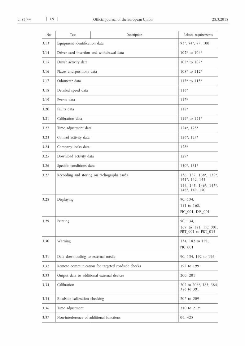
No Test Description Related requirements
3.13 Equipment identification data 93*, 94*, 97, 100
3.14 Driver card insertion and withdrawal data 102* to 104*
3.15 Driver activity data 105* to 107*
3.16 Places and positions data 108* to 112*
3.17 Odometer data 113* to 115*
3.18 Detailed speed data 116*
3.19 Events data 117*
3.20 Faults data 118*
3.21 Calibration data 119* to 121*
3.22 Time adjustment data 124*, 125*
3.23 Control activity data 126*, 127*
3.24 Company locks data 128*
3.25 Download activity data 129*
3.26 Specific conditions data 130*, 131*
3.27 Recording and storing on tachographs cards 136, 137, 138*, 139*, 141*, 142, 143
144, 145, 146*, 147*, 148*, 149, 150
3.28 Displaying 90, 134,
151 to 168,
PIC_001, DIS_001
3.29 Printing 90, 134,
169 to 181, PIC_001, PRT_001 to PRT_014
3.30 Warning 134, 182 to 191,
PIC_001
3.31 Data downloading to external media 90, 134, 192 to 196
3.32 Remote communication for targeted roadside checks 197 to 199
3.33 Output data to additional external devices 200, 201
3.34 Calibration 202 to 206*, 383, 384, 386 to 391
3.35 Roadside calibration checking 207 to 209
3.36 Time adjustment 210 to 212*
3.37 Non-interference of additional functions 06, 425
EN L 85/44 Official Journal of the European Union 28.3.2018

No Test Description Related requirements
3.38 Motion sensor interface 02, 122
3.39 External GNSS facility 03, 123
3.40 Verify that the VU detects, records and stores the event(s) and/or fault(s) defined by the VU manufacturer when a paired motion sensor reacts to magnetic fields disturbing vehicle motion detection.
217
3.41 Cypher suite and standardized domain parameters CSM_48, CSM_50
4 Environmental tests
4.1 Temperature Verify functionality through:
Test according to ISO 16750-4, Chapter 5.1.1.2: Low temperature operation test (72 h @ – 20 °C)
This test refers to IEC 60068-2-1: Environmental testing - Part 2-1: Tests - Test A: Cold
Test according to ISO 16750-4: Chapter 5.1.2.2: High temperature operation test (72 h at 70 °C)
This test refers to IEC 60068-2-2: Basic environmental testing procedures; part 2: tests; tests B: dry heat
Test according to ISO 16750-4: Chapter 5.3.2: Rapid change of temperature with specified transition duration (– 20 °C/70 °C, 20 cycles, dwell time 2h at each temperature)
A reduced set of tests (among those defined in section 3 of this table) can be carried out at the lower temperature, the higher temperature and during the temperature cycles
213
4.2 Humidity Verify that the vehicle unit can withstand a cyclic damp (heat test) through IEC 60068-2-30, test Db, six 24 hours cycles, each temperature varying from +25 °C to + 55 °C and a relative humidity of 97 % at + 25 °C and equal to 93 % at +55 °C
214
4.3 Mechanical 1. Sinusoidal vibrations.
verify that the vehicle unit can withstand sinusoidal vibrations with the following characteristics:
constant displacement between 5 and 11 Hz: 10mm peak
constant acceleration between 11 and 300 Hz: 5g
This requirement is verified through IEC 60068- 2-6, test Fc, with a minimum test duration of 3 × 12 hours (12 hours per axis)
ISO 16750-3 does not require a sinusoidal vibration test for devices located in the decoupled vehicle cab.
219
EN 28.3.2018 Official Journal of the European Union L 85/45

No Test Description Related requirements
2. Random vibrations:
Test according to ISO 16750-3: Chapter 4.1.2.8: Test VIII: Commercial vehicle, decoupled vehicle cab
Random vibration test, 10…2000 Hz, RMS vertical 21,3 m/s 2 , RMS longitudinal 11,8 m/s 2 , RMS lateral 13,1 m/s 2 , 3 axes, 32 h per axis, including temperature cycle – 20…70 °C.
This test refers to IEC 60068-2-64: Environmental testing - Part 2-64: Tests - Test Fh: Vibration, broadband random and guidance
3. Shocks:
mechanical shock with 3 g half sinus according ISO 16750.
The tests described above are performed on different samples of the equipment type being tested.
4.4 Protection against water and foreign bodies
Test according to ISO 20653: Road vehicles – Degree of protection (IP code) – Protection of electrical equipment against foreign objects, water and access (No change in parameters); Minimum value IP 40
220, 221
4.5 Over-voltage protection
Verify that the vehicle unit can withstand a power supply of:
24 V versions: 34V at + 40 °C 1 hour
12V versions: 17V at + 40 °C 1 hour(ISO 16750-2)
216
4.6 Reverse polarity protection
Verify that the vehicle unit can withstand an inversion of its power supply
(ISO 16750-2)
216
4.7 Short-circuit protection
Verify that input output signals are protected against short circuits to power supply and ground
(ISO 16750-2)
216
5 EMC tests
5.1 Radiated emissions and susceptibility
Compliance with Regulation ECE R10 218
5.2 Electrostatic discharge
Compliance with ISO 10605:2008 +
Technical Corrigendum:2010 +
AMD1:2014: +/– 4 kV for contact and +/– 8 kV for air discharge
218
EN L 85/46 Official Journal of the European Union 28.3.2018
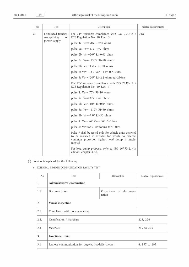
No Test Description Related requirements
5.3 Conducted transient susceptibility on power supply
For 24V versions: compliance with ISO 7637-2 + ECE Regulation No. 10 Rev. 3:
pulse 1a: Vs=450V Ri=50 ohms
pulse 2a: Vs=+37V Ri=2 ohms
pulse 2b: Vs=+20V Ri=0,05 ohms
pulse 3a: Vs=– 150V Ri=50 ohms
pulse 3b: Vs=+150V Ri=50 ohms
pulse 4: Vs=– 16V Va=– 12V t6=100ms
pulse 5: Vs=+120V Ri=2,2 ohms td=250ms
For 12V versions: compliance with ISO 7637– 1 + ECE Regulation No. 10 Rev. 3:
pulse 1: Vs=– 75V Ri=10 ohms
pulse 2a: Vs=+37V Ri=2 ohms
pulse 2b: Vs=+10V Ri=0,05 ohms
pulse 3a: Vs=– 112V Ri=50 ohms
pulse 3b: Vs=+75V Ri=50 ohms
pulse 4: Vs=– 6V Va=– 5V t6=15ms
pulse 5: Vs=+65V Ri=3ohms td=100ms
Pulse 5 shall be tested only for vehicle units designed to be installed in vehicles for which no external common protection against load dump is implemented
For load dump proposal, refer to ISO 16750-2, 4th edition, chapter 4.6.4.
218’
(d) point 6 is replaced by the following:
‘6. EXTERNAL REMOTE COMMUNICATION FACILITY TEST
No Test Description Related requirements
1. Administrative examination
1.1 Documentation Correctness of documentation
2. Visual inspection
2.1. Compliance with documentation
2.2. Identification / markings 225, 226
2.3 Materials 219 to 223
3. Functional tests
3.1 Remote communication for targeted roadside checks 4, 197 to 199
EN 28.3.2018 Official Journal of the European Union L 85/47
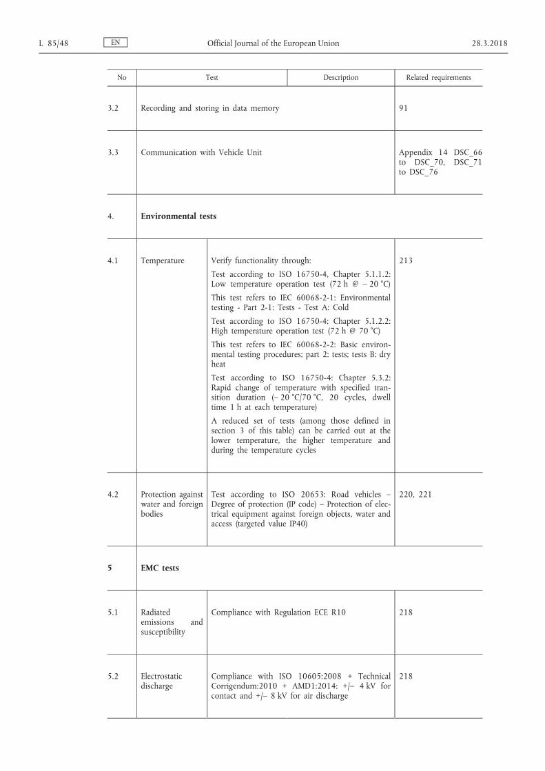
No Test Description Related requirements
3.2 Recording and storing in data memory 91
3.3 Communication with Vehicle Unit Appendix 14 DSC_66 to DSC_70, DSC_71 to DSC_76
4. Environmental tests
4.1 Temperature Verify functionality through:
Test according to ISO 16750-4, Chapter 5.1.1.2: Low temperature operation test (72 h @ – 20 °C)
This test refers to IEC 60068-2-1: Environmental testing - Part 2-1: Tests - Test A: Cold
Test according to ISO 16750-4: Chapter 5.1.2.2: High temperature operation test (72 h @ 70 °C)
This test refers to IEC 60068-2-2: Basic environmental testing procedures; part 2: tests; tests B: dry heat
Test according to ISO 16750-4: Chapter 5.3.2: Rapid change of temperature with specified transition duration (– 20 °C/70 °C, 20 cycles, dwell time 1 h at each temperature)
A reduced set of tests (among those defined in section 3 of this table) can be carried out at the lower temperature, the higher temperature and during the temperature cycles
213
4.2 Protection against water and foreign bodies
Test according to ISO 20653: Road vehicles – Degree of protection (IP code) – Protection of electrical equipment against foreign objects, water and access (targeted value IP40)
220, 221
5 EMC tests
5.1 Radiated emissions and susceptibility
Compliance with Regulation ECE R10 218
5.2 Electrostatic discharge
Compliance with ISO 10605:2008 + Technical Corrigendum:2010 + AMD1:2014: +/– 4 kV for contact and +/– 8 kV for air discharge
218
EN L 85/48 Official Journal of the European Union 28.3.2018

No Test Description Related requirements
5.3 Conducted transient susceptibility on power supply
For 24V versions: compliance with ISO 7637-2 + ECE Regulation No. 10 Rev. 3:
pulse 1a: Vs=– 450V Ri=50 ohms
pulse 2a: Vs=+37V Ri=2 ohms
pulse 2b: Vs=+20V Ri=0,05 ohms
pulse 3a: Vs=– 150V Ri=50 ohms
pulse 3b: Vs=+150V Ri=50 ohms
pulse 4: Vs=– 16V Va=-12V t6=100ms
pulse 5: Vs=+120V Ri=2,2 ohms td=250ms
For 12V versions: compliance with ISO 7637-1 + ECE Regulation No. 10 Rev. 3:
pulse 1: Vs=-75V Ri=10 ohms
pulse 2a: Vs=+37V Ri=2 ohms
pulse 2b: Vs=+10V Ri=0,05 ohms
pulse 3a: Vs=– 112V Ri=50 ohms
pulse 3b: Vs=+75V Ri=50 ohms
pulse 4: Vs=– 6V Va=– 5V t6=15ms
pulse 5: Vs=+65V Ri=3ohms td=100ms
Pulse 5 shall be tested only for vehicle units designed to be installed in vehicles for which no external common protection against load dump is implemented
For load dump proposal, refer to ISO 16750-2, 4th edition, chapter 4.6.4.
218’
(e) the table in point 8 on interoperability tests is replaced by the following:
‘No Test Description
8.1 Interoperability tests between vehicle units and tachograph cards
1 Mutual authentication Check that the mutual authentication between the vehicle unit and the tachograph card runs normally
2 Write/read tests Execute a typical activity scenario on the vehicle unit. The scenario shall be adapted to the type of card being tested and involve writings in as many EFs as possible in the card
Verify through a vehicle unit downloading that all corresponding recordings have been properly made
Verify through a card downloading that all corresponding recordings have been properly made
Verify through daily printouts that all corresponding recordings can be properly read
EN 28.3.2018 Official Journal of the European Union L 85/49

No Test Description
8.2 Interoperability tests between vehicle units and motion sensors
1 Pairing Check that the pairing between the vehicle units and the motion sensors runs normally
2 Activity tests Execute a typical activity scenario on the motion sensor. The scenario shall involve a normal activity and creating as many events or faults as possible.
Verify through a vehicle unit downloading that all corresponding recordings have been properly made
Verify through a card downloading that all corresponding recordings have been properly made
Verify through a daily printout that all corresponding recordings can be properly read
8.3 Interoperability tests between vehicle units and external GNSS facilities (when applicable)
1 Mutual authentication Check that the mutual authentication (coupling) between the vehicle unit and the external GNSS module runs normally.
2 Activity tests Execute a typical activity scenario on the external GNSS facility. The scenario shall involve a normal activity and creating as many events or faults as possible.
Verify through a vehicle unit downloading that all corresponding recordings have been properly made
Verify through a card downloading that all corresponding recordings have been properly made
Verify through a daily printout that all corresponding recordings can be properly read’
(36) Appendix 11 is amended as follows:
(a) in point 8.2.3, paragraph CSM_49 is replaced by the following:
‘CSM_49 Vehicle units, tachograph cards and external GNSS facilities shall support the SHA-256, SHA-384 and SHA-512 algorithms specified in [SHS].’;
(b) in point 9.1.2, the first sub-paragraph of paragraph CSM_58 is replaced by the following:
‘CSM_58 Whenever it generates a new European root key pair, the ERCA shall create a link certificate for the new European public key and sign it with the previous European private key. The validity period of the link certificate shall be 17 years plus 3 months. This is shown in Figure 1 in section 9.1.7 as well.’;
(c) in point 9.1.4, paragraph CSM_72 is replaced by the following:
‘CSM_72 Two unique ECC key pairs shall be generated for each vehicle unit, designated as VU_MA and VU_Sign. This task is handled by VU manufacturers. Whenever a VU key pair is generated, the party generating the key shall send the public key to its MSCA, in order to obtain a corresponding VU certificate signed by the MSCA. The private key shall be used only by the vehicle unit.’;
EN L 85/50 Official Journal of the European Union 28.3.2018

(d) point 9.1.5 is amended as follows:
(i) paragraph CSM_83 is replaced by the following:
‘CSM_83 One unique ECC key pair, designated as Card_MA, shall be generated for each tachograph card. A second unique ECC key pair, designated as Card_Sign, shall additionally be generated for each driver card and each workshop card. This task may be handled by card manufacturers or card personalisers. Whenever a card key pair is generated, the party generating the key shall send the public key to its MSCA, in order to obtain a corresponding card certificate signed by the MSCA. The private key shall be used only by the tachograph card.’;
(ii) paragraph CSM_88 is replaced by the following:
‘CSM_88 The validity period of a Card_MA certificate shall be as follows:
— For driver cards: 5 years
— For company cards: 5 years
— For control cards: 2 years
— For workshop cards: 1 year’;
(iii) the following text is added in paragraph CSM_91:
‘— Additionally, for control cards, company cards and workshop cards only, and only if such cards are issued during the first three months of the validity period of a new EUR certificate: the EUR certificate that is two generations older, if existing.
Note to last bullet: For example, in the first three months of the ERCA(3) certificate (see Figure 1), the mentioned cards shall contain the ERCA(1) certificate. This is needed to ensure that these cards can be used to perform data downloads from ERCA(1) VUs whose normal 15-year life period plus the 3- months data downloading period expires during these months; see the last bullet of requirement 13) in Annex IC.’;
(e) point 9.1.6 is amended as follows:
(i) paragraph CSM_93 is replaced by the following:
‘CSM_93 One unique ECC key pair shall be generated for each external GNSS facility, designated as EGF_MA. This task is handled by external GNSS facility manufacturers. Whenever an EGF_MA key pair is generated, the party generating th e key shall send the public key to its MSCA in order to obtain a corresponding EGF_MA certificate signed by the MSCA. The private key shall be used only by the external GNSS facility.’;
(ii) paragraph CSM_95 is replaced by the following:
‘CSM_95 An external GNSS facility shall use its EGF_MA key pair, consisting of private key EGF_MA.SK and public key EGF_MA.PK, exclusively to perform mutual authentication and session key agreement towards vehicle units, as specified in section 11.4 of this Appendix.’;
EN 28.3.2018 Official Journal of the European Union L 85/51

(f) point 9.1.7 is amended as follows:
(i) Figure 1 is replaced by the following:
‘Figure 1
Issuance and usage of different generations of ERCA root certificates, ERCA link certificates, MSCA certificates and equipment certificates
’
(ii) paragraph 6 in the Notes to Figure 1 is replaced by the following:
‘6. To save space, the difference in validity period between the Card_MA and Card_Sign certificates is shown only for the first generation.’;
EN L 85/52 Official Journal of the European Union 28.3.2018

(g) point 9.2.1.1 is amended as follows:
(i) in paragraph CSM_106, the first dash is replaced by the following:
‘— For 128-bit motion sensor master keys: CV = “B6 44 2C 45 0E F8 D3 62 0B 7A 8A 97 91 E4 5D 83” ’;
(ii) in paragraph CSM_107, the first sub-paragraph is replaced by the following:
‘Each Motion sensor manufacturer shall generate a random and unique pairing key K P for every motion sensor, and shall send each pairing key to its Member State Certificate Authority. The MSCA shall encrypt each pairing key separately with the motion sensor master key K M and shall return the encrypted key to the motion sensor manufacturer. For each encrypted key, the MSCA shall notify the motion sensor manufacturer of the version number of the associated K M .’;
(iii) paragraph CSM_108 is replaced by the following:
‘CSM_108 Each motion sensor manufacturer shall generate a unique serial number for every motion sensor, and shall send all serial numbers to its Member State Certificate Authority. The MSCA shall encrypt each serial number separately with the identification key K ID and shall return the encrypted serial number to the motion sensor manufacturer. For each encrypted serial number, the MSCA shall notify the motion sensor manufacturer of the version number of the associated K ID .’;
(h) point 9.2.2.1 is amended as follows:
(i) paragraph CSM_123 is replaced by the following:
‘CSM_123 For every vehicle unit, the vehicle unit manufacturer shall create a unique VU serial number and shall send this number to its Member State Certificate Authority in a request to obtain a set of two VU-specific DSRC keys. The VU serial number shall have data type .
Note:
— This VU serial number shall be identical to the vuSerialNumber element of VuIdentification, see Appendix 1 and to the Certificate Holder Reference in the VU’s certificates.
— The VU serial number may not be known at the moment a vehicle unit manufacturer requests the VU-specific DSRC keys. In this case, the VU manufacturer shall send instead the unique certificate request ID it used when requesting the VU’s certificates; see CSM_153. This certificate request ID shall therefore be equal to the Certificate Holder Reference in the VU’s certificates.’;
(ii) in paragraph CSM_124, the info requirement in step 2 is replaced by the following:
‘info = VU serial number or certificate request ID, as specified in CSM_123’;
(iii) paragraph CSM_128 is replaced by the following:
‘CSM_128 The MSCA shall keep records of all VU-specific DSRC keys it generated, their version number and the VU serial number or certificate request ID used in deriving them.’;
(i) in point 9.3.1, the first sub-paragraph in paragraph CSM_135 is replaced by the following:
‘The Distinguished Encoding Rules (DER) according to [ISO 8825-1] shall be used to encode the data objects within certificates. Table 4 shows the full certificate encoding, including all tag and length bytes.’;
EN 28.3.2018 Official Journal of the European Union L 85/53
(j) in point 9.3.2.3, paragraph CSM_141 is replaced by the following:
‘CSM_141 The Certificate Holder Authorisation shall be used to identify the type of certificate. It consists of the six most significant bytes of the Tachograph Application ID, concatenated with the equipment type, which indicates the type of equipment for which the certificate is intended. In the case of a VU certificate, a driver card certificate or a workshop card certificate, the equipment type is also used to differentiate between a certificate for Mutual Authentication and a certificate for creating digital signatures (see section 9.1 and Appendix 1, data type EquipmentType).’;
(k) in point 9.3.2.5, the following sub-paragraph is added in paragraph CSM_146:
‘Note: For a card certificate, the value of the CHR shall be equal to the value of the cardExtendedSerialNumber in EF_ICC; see Appendix 2. For an EGF certificate, the value of the CHR shall be equal to the value of the sensorGNSSSerialNumber in EF_ICC; see Appendix 14. For a VU certificate, the value of the CHR shall be equal to the vuSerialNumber element of VuIdentification, see Appendix 1, unless the manufacturer does not know the manufacturer-specific serial number at the time the certificate is requested.’;
(l) in point 9.3.2.6, paragraph CSM_148 is replaced by the following:
‘CSM_148 The Certificate Effective Date shall indicate the starting date and time of the validity period of the certificate.’;
(m) point 9.3.3 is amended as follows:
(i) in paragraph CSM_151, the first sub-paragraph is replaced by the following:
‘When requesting a certificate, an MSCA shall send the following data to the ERCA:’;
(ii) paragraph CSM_153 is replaced by the following:
‘CSM_153 An equipment manufacturer shall send the following data in a certificate request to an MSCA, allowing the MSCA to create the Certificate Holder Reference of the new equipment certificate:
— If known (see CSM_154), a serial number for the equipment, unique for the manufacturer, the equipment's type and the month of manufacturing. Otherwise, a unique certificate request identifier.
— The month and the year of equipment manufacturing or of the certificate request.
The manufacturer shall ensure that this data is correct and that the certificate returned by the MSCA is inserted in the intended equipment.’;
(n) point 10.2.1 is amended as follows:
(i) in paragraph CSM_157, the text before the Notes to Figure 4 is replaced by the following:
‘Vehicle units shall use the protocol depicted in Figure 4 for verifying a tachograph card’s certificate chain. For every certificate it reads from the card, the VU shall verify that the Certificate Holder Authorisation (CHA) field is correct:
— The CHA field of the Card certificate shall indicate a card certificate for mutual authentication (see Appendix 1, data type EquipmentType).
EN L 85/54 Official Journal of the European Union 28.3.2018

— The CHA of the Card.CA certificate shall indicate an MSCA.
— The CHA of the Card.Link certificate shall indicate the ERCA.’;
(ii) in paragraph CSM_159, the following sentence is added:
‘Whereas storing of all other types of certificate is optional, it is mandatory for a VU to store a new link certificate presented by a card.’;
(o) point 10.2.2 is amended as follows:
(i) in paragraph CSM_161, the text before the Figure 5 is replaced by the following:
‘Tachograph cards shall use the protocol depicted in Figure 5 for verifying a VU's certificate chain. For every certificate presented by the VU, the card shall verify that the Certificate Holder Authorisation (CHA) field is correct:
— The CHA of the VU.Link certificate shall indicate the ERCA.
— The CHA of the VU.CA certificate shall indicate an MSCA.
— The CHA field of the VU certificate shall indicate a VU certificate for mutual authentication (see Appendix 1, data type EquipmentType).’;
(ii) paragraph CSM_165 is replaced by the following:
‘CSM_165 If the MSE: Set AT command is successful, the card shall set the indicated VU.PK for subsequent use during Vehicle Authentication, and shall temporarily store Comp(VU.PKeph). In case two or more successful MSE: Set AT commands are sent before session key agreement is performed, the card shall store only the last Comp(VU.PKeph) received. The card shall reset Comp(VU.PKeph) after a successful GENERAL AUTHENTICATE command.’;
(p) point 10.3 is amended as follows:
(i) the first sub-paragraph in paragraph CSM_170 is replaced by the following:
‘Next to the card challenge, the VU shall include in the signature the certificate holder reference taken from the card certificate.’;
EN 28.3.2018 Official Journal of the European Union L 85/55

(ii) in paragraph CSM_171, Figure 6 is replaced by the following:
‘Figure 6
VU Authentication protocol
’
(iii) paragraph CSM_174 is replaced by the following:
‘CSM_174 Upon receiving the VU’s signature in an EXTERNAL AUTHENTICATE command, the card shall
— Calculate the authentication token by concatenating Card.CHR, the card challenge rcard and the identifier of the VU ephemeral public key Comp(VU.PKeph),
— Verify the VU’s signature using the ECDSA algorithm, using the hashing algorithm linked to the key size of the VU’s VU_MA key pair as specified in CSM_50, in combination with VU.PK and the calculated authentication token.’;
(q) in point 10.4, paragraph CSM_176 is amended as follows:
(i) sub-paragraph 2 is replaced by the following:
‘2. The VU sends the public point VU.PK eph of its ephemeral key pair to the card. The public point shall be converted to an octet string as specified in [TR-03111]. The uncompressed encoding format shall be used. As explained in CSM_164, the VU generated this ephemeral key pair prior to the verification of the VU certificate chain. The VU sent the identifier of the ephemeral public key Comp(VU.PK eph ) to the card, and the card stored it.’;
(ii) sub-paragraph 6 is replaced by the following:
‘6. Using K MAC , the card computes an authentication token over the VU ephemeral public point: T PICC = CMAC(K MAC , VU.PK eph ). The public point shall be in the format used by the VU (see bullet 2 above). The card sends N PICC and T PICC to the vehicle unit.’;
EN L 85/56 Official Journal of the European Union 28.3.2018

(r) in point 10.5.2, paragraph CSM_191 is replaced by the following:
‘CSM_191 Any data object to be encrypted shall be padded according to [ISO 7816-4] using padding-content indicator ‘01’. For the calculation of the MAC, data objects in the APDU shall be padded according to [ISO 7816-4].
Note: Padding for Secure Messaging is always performed by the secure messaging layer, not by the CMAC or CBC algorithms.
Summary and Examples
A command APDU with applied Secure Messaging will have the following structure, depending on the case of the respective unsecured command (DO is data object):
Case 1: CLA INS P1 P2 || Lc' || DO ‘8E’ || Le
Case 2: CLA INS P1 P2 || Lc' || DO ‘97’ || DO‘8E’ || Le
Case 3 (even INS byte): CLA INS P1 P2 || Lc' || DO ‘81’ || DO‘8E’ || Le
Case 3 (odd INS byte): CLA INS P1 P2 || Lc' || DO ‘B3’ || DO‘8E’ || Le
Case 4 (even INS byte): CLA INS P1 P2 || Lc' || DO ‘81’ || DO‘97’ || DO‘8E’ || Le
Case 4 (odd INS byte): CLA INS P1 P2 || Lc' || DO ‘B3’ || DO‘97’ || DO‘8E’ || Le
where Le = ‘00’ or ‘00 00’ depending on whether short length fields or extended length fields are used; see [ISO 7816-4].
A response APDU with applied Secure Messaging will have the following structure, depending on the case of the respective unsecured response:
Case 1 or 3: DO ‘99’ || DO ‘8E’ || SW1SW2
Case 2 or 4 (even INS byte) without encryption: DO ‘81’ || DO ‘99’ || DO ‘8E’ || SW1SW2
Case 2 or 4 (even INS byte) with encryption: DO ‘87’ || DO ‘99’ || DO ‘8E’ || SW1SW2
Case 2 or 4 (odd INS byte) without encryption: DO ‘B3’ || DO ‘99’ || DO ‘8E’ || SW1SW2
Note: Case 2 or 4 (odd INS byte) with encryption is never used in the communication between a VU and a card.
Below are three example APDU transformations for commands with even INS code. Figure 8 shows an authenticated Case 4 command APDU, Figure 9 shows an authenticated Case 1/Case 3 response APDU, and Figure 10 shows an encrypted and authenticated Case 2/Case 4 response APDU.
EN 28.3.2018 Official Journal of the European Union L 85/57

Figure 8
Transformation of an authenticated Case 4 Command APDU
Figure 9
Transformation of an authenticated Case 1 / Case 3 Response APDU
EN L 85/58 Official Journal of the European Union 28.3.2018

Figure 10
Transformation of an encrypted and authenticated Case 2/Case 4 Response APDU
’
(s) in point 10.5.3, paragraph CSM_193 is replaced by the following:
‘CSM_193 A tachograph card shall abort an ongoing Secure Messaging session if and only if one of the following conditions occur:
— it receives a plain command APDU,
— it detects a Secure Messaging error in a command APDU:
— An expected Secure Messaging data object is missing, the order of data objects is incorrect, or an unknown data object is included.
— A Secure Messaging data object is incorrect, e.g. the MAC value is incorrect or the TLV structure is incorrect.
— it is depowered or reset,
— the VU starts the VU Authentication process,
— the limit for the number of commands and associated responses within the current session is reached. For a given card, this limit shall be defined by its manufacturer, taking into account the security requirements of the hardware used, with a maximum value of 240 SM commands and associated responses per session’;
EN 28.3.2018 Official Journal of the European Union L 85/59

(t) point 11.3.2 is amended as follows:
(i) the first sub-paragraph of paragraph CSM_208 is replaced by the following:
‘During the coupling to a VU, an external GNSS facility shall use the protocol depicted in Figure 5 (section 10.2.2) for verifying the VU's certificate chain’;
(ii) paragraph CSM_210 is replaced by the following:
‘CSM_210 Once it has verified the VU_MA certificate, the external GNSS facility shall store this certificate for use during normal operation; see section 11.3.3.’;
(u) in point 11.3.3, the first sub-paragraph in paragraph CSM_211, is replaced by the following:
‘During normal operation, a vehicle unit and an EGF shall use the protocol depicted in Figure 11 for verifying the temporal validity of the stored EGF_MA certificate and for setting the VU_MA public key for subsequent VU Authentication. No further mutual verification of the certificate chains shall take place during normal operation.’;
(v) in point 12.3, Table 6 is replaced by the following:
‘Table 6
Number of plaintext and encrypted data bytes per instruction defined in [ISO 16844-3]
Instruction Request / reply Description of data
# of plaintext data bytes according to
[ISO 16844-3]
# of plaintext data bytes using AES keys
# of encrypted data bytes when using AES keys of bitlength
128 192 256
10 request Authentication data + file number
8 8 16 16 16
11 reply Authentication data + file contents
16 or 32, depend on file
16 or32, depend on file
32 / 48 32 / 48 32 / 48
41 request MoS serial number 8 8 16 16 16
41 reply Pairing key 16 16 / 24 / 32 16 32 32
42 request Session key 16 16 / 24 / 32 16 32 32
43 request Pairing information 24 24 32 32 32
50 reply Pairing information 24 24 32 32 32
70 request Authentication data 8 8 16 16 16
80 reply MoS counter value + auth. data
8 8 16 16 16’
(w) in point 13.1, the requirement on the VU serial number in subparagraph CSM_224 is replaced by the following:
‘VU serial number the VU’s serial number or certificate request ID (data type VuSerialNumber or CertificateRequestID) – see CSM_123’;
EN L 85/60 Official Journal of the European Union 28.3.2018

(x) in point 13.3, the second indent in paragraph CSM_228 is replaced by the following:
‘2. The control card shall use the indicated DSRC master key in combination with the VU serial number or the certificate request ID in the DSRC security data to derive the VU-specific DSRC keys K_VU DSRC _ENC and K_VU DSRC _MAC, as specified in CSM_124.’;
(y) point 14.3 is amended as follows:
(i) in paragraph CSM_234, the text before the Notes to figure 13 is replaced by the following:
‘An IDE may perform verification of a signature over downloaded data itself or it may use a control card for this purpose. In case it uses a control card, signature verification shall take place as shown in Figure 13. For verifying the temporal validity of a certificate presented by the IDE, the control card shall use its internal current time, as specified in CSM_167. The control card shall update its current time if the Effective Date of an authentic ‘valid source of time’ certificate is more recent than the card’s current time. The card shall accept only the following certificates as a valid source of time:
— Second-generation ERCA link certificates
— Second-generation MSCA certificates
— Second-generation VU_Sign or Card_Sign certificates issued by the same country as the control card’s own card certificate.
In case it performs signature verification itself, the IDE shall verify the authenticity and validity of all certificates in the certificate chain in the data file, and it shall verify the signature over the data following the signature scheme defined in [DSS]. In both cases, for every certificate read from the data file, it is necessary to verify that the Certificate Holder Authorisation (CHA) field is correct:
— The CHA field of the EQT certificate shall indicate a VU or Card (as applicable) certificate for signing (see Appendix 1, data type EquipmentType).
— The CHA of the EQT.CA certificate shall indicate an MSCA.
— The CHA of the EQT.Link certificate shall indicate the ERCA.’;
(ii) Figure 13 is replaced by the following:
EN 28.3.2018 Official Journal of the European Union L 85/61

‘Figure 13
Protocol for verification of the signature over a downloaded data file
’
EN L 85/62 Official Journal of the European Union 28.3.2018

(37) Appendix 12 is amended as follows:
(a) point 3 is amended as follows:
(i) in paragraph GNS_4, the second sub-paragraph after Figure 2 is replaced by the following:
‘The resolution of the position is based on the format of the RMC sentence described above. The first part of the fields 3) and 5) are used to represent the degrees. The rest are used to represent the minutes with three decimals. So the resolution is 1/1000 of minute or 1/60000 of degree (because one minute is 1/60 of a degree).’;
(ii) Paragraph GNS_5 is replaced by the following:
‘GNS_5 The Vehicle Unit shall store in the VU database the position information for latitude and longitude with a resolution of 1/10 of minute or 1/600 of a degree as described in Appendix 1 for type GeoCoordinates.
The GPS DOP and active satellites (GSA) command can be used by the VU to determine and record the signal availability and accuracy. In particular the HDOP is used to provide an indication on the level of accuracy of the recorded location data (see 4.2.2). The VU will store the value of the Horizontal Dilution of Precision (HDOP) calculated as the minimum of the HDOP values collected on the available GNSS systems.
The GNSS Id. indicates the corresponding NMEA Id. for every GNSS constellation and Satellite- Based Augmentation System (SBAS).
Figure 3
Structure of the GSA sentence
’
(iii) paragraph GNS_6 is replaced by the following:
‘GNS_6 The GSA sentence shall be stored with record number ‘02’ to ‘06’’;
(b) point 4.2.1 is amended as follows:
(i) paragraph GNS_16 is replaced by the following:
‘GNS_16 In the communication protocol, extended length fields shall not be supported.’;
EN 28.3.2018 Official Journal of the European Union L 85/63

(ii) paragraph GNS_18 is replaced by the following:
‘GNS_18 Regarding the functions 1) the collection and distribution of GNSS data and 2) the collection of the configuration data of the external GNSS facility and 3) management protocol, the GNSS Secure Transceiver shall simulate a smart card with a file system architecture composed by a Master File (MF), a Dedicated File (DF) with Application Identifier specified in Appendix 1 chapter 6.2 (‘FF 44 54 45 47 4D’) and with 3 EFs containing certificates and one single Elementary File (EF.EGF) with file identifier equal to ‘2F2F’ as described in Table 1.’;
(iii) paragraph GNS_20 is replaced by the following:
‘GNS_20 The GNSS Secure Transceiver shall use a memory to store the data and be able to perform at least 20 millions write/read cycles. Apart from this aspect, the internal design and implementation of the GNSS Secure Transceiver is left to the manufacturers.
The mapping of record numbers and data is provided in Table 1. Note that there are five GSA sentences for the GNSS constellations and Satellite-Based Augmentation System (SBAS).’;
(c) in point 4.2.2, sub-paragraph 5 in paragraph GNS_23 is replaced by the following:
‘5. The VU processor checks the received data extracting the information (e.g., latitude, longitude, time) from the RMC NMEA sentence. The RMC NMEA sentence includes the information if the position is valid. If the position is not valid, the location data is not available yet and it cannot be used to record the position of the vehicle. If the position is valid, the VU processor also extracts the values of HDOP from GSA NMEA sentences and calculate the minimum value on the available satellite systems (i.e., when the fix is available).’;
(d) In point 4.4.1, paragraph GNS_28 is replaced by the following:
‘GNS_28 If the VU does not manage to communicate to the coupled external GNSS facility for more than 20 continuous minutes, the VU shall generate and record in the VU an event of type EventFaultType with the value of enum ‘0E’H Communication error with the external GNSS facility and with the timestamp set to the current time. The event will be generated only if the following two conditions are satisfied: (a) the Smart Tachograph is not in calibration mode and (b) the vehicle is moving. In this context, a communication error is triggered when the VU Secure Transceiver does not receive a response message after a request message as described in 4.2.’;
(e) in point 4.4.2, paragraph GNS_29 is replaced by the following:
‘GNS_29 If the external GNSS facility has been breached, the GNSS Secure Transceiver shall erase all its memory including cryptographic material. As described in GNS_25 and GNS_26, the VU shall detect tampering if the Response has status ‘6690’. The VU shall then generate an event of type EventFaultType enum ‘19’H Tamper detection of GNSS. Alternately, the external GNSS facility may not respond to any external request anymore.’;
(f) in point 4.4.3, paragraph GNS_30 is replaced by the following:
‘GNS_30 If the GNSS Secure Transceiver does not receive data from the GNSS receiver for more than 3 continuous hours, the GNSS Secure Transceiver shall generate a response message to the READ RECORD command with RECORD number equal to ‘01’ with a Data Field of 12 bytes all set to 0xFF. Upon reception of the Response message with this value of the data field, the VU shall generate and record an event of type EventFaultType enum ‘0D’H Absence of position information from GNSS receiver event with a timestamp equal to the current value of time only if the following two conditions are satisfied: a) the Smart Tachograph is not in calibration mode and b) the vehicle is moving.’;
EN L 85/64 Official Journal of the European Union 28.3.2018

(g) in point 4.4.4, the text in paragraph GNS_31 until Figure 4, is replaced by the following:
‘If the VU detects that the EGF certificate used for mutual authentication is not valid any longer, the VU shall generate and record a recording equipment event of type EventFaultType enum ‘1B’H External GNSS facility certificate expired with a timestamp equal to the current value of time. The VU shall still use the received GNSS position data.’;
(h) in point 5.2.1, paragraph GNS_34 is replaced by the following:
‘GNS_34 If the VU does not receive data from the GNSS receiver for more than 3 continous hours, the VU shall generate and record an event of type EventFaultType enum ‘0D’H Absence of position information from GNSS receiver event with a timestamp equal to the current value of time only if the following two conditions are satisfied: (a) the Smart Tachograph is not in calibration mode and (b) the vehicle is moving.’;
(i) point 6 is replaced by the following:
‘6. GNSS TIME CONFLICT
If the VU detects a discrepancy of more than 1 minute between the time of the vehicle unit's time measurement function and the time originating from the GNSS receiver, the VU will record an event of type EventFaultType enum ‘0B’H Time conflict (GNSS versus VU internal clock). After a time conflict event has been triggered, the VU will not check the time discrepancy for the next 12 hours. This event shall not be triggered in cases no valid GNSS signal was detectable by the GNSS receiver within the last 30 days.’;
(38) Appendix 13 is amended as follows:
(a) in point 2, the fourth paragraph is replaced by the following:
‘For clarification, this Appendix does not specify:
— The collection of the Data operation and management within the VU (which shall be specified elsewhere within the Regulation or otherwise shall be a function of product design).
— The form of presentation of collected data to application hosted on the external device.
— Data security provisions above what provides Bluetooth® (such as encryption) concerning the content of the Data (which shall be specified elsewhere within the Regulation [Appendix 11 Common Security Mechanisms]).
— The Bluetooth® protocols used by the ITS interface’;
(b) in point 4.2, the third paragraph is replaced by the following:
‘When an external device comes within range of the VU for the first time, the Bluetooth® pairing process can be initiated (see also annex 2). The devices share their addresses, names, and profiles and common secret key, which allows them to bond whenever they are together in the future. Once this step is completed, the external device is trusted and is in state to initiate requests to download data from the tachograph. It is not foreseen to add encryption mechanisms beyond what Bluetooth® provides. However, if additional security mechanisms are needed, this will be done in accordance with Appendix 11 Common Security Mechanisms.’;
(c) point 4.3 is amended as follows:
(i) the first paragraph is replaced by the following:
‘For security reasons, the VU will require a PIN code authorization system separated from the Bluetooth pairing. Each VU shall be able to generate PIN codes for authentication purposes composed of at least 4 digits. Every time an external device pairs with the VU, it must provide the correct PIN code before receiving any data.’;
EN 28.3.2018 Official Journal of the European Union L 85/65

(ii) the third paragraph after Table 1 is replaced by the following:
‘While the manufacturer may offer an option to change the PIN code directly through the VU, the PUC code shall not be alterable. Modifying the PIN code, if possible, shall require to enter the current PIN code directly in the VU.’;
(d) in point 4.4, the second paragraph after the heading "Data Field" is replaced by the following:
‘If the data to be handled is larger than the available space in one message, it will be split in several submessages. Each submessage shall have the same Header and SID, but will contain a 2-bytes counter, Counter Current (CC) and Counter Max (CM), to indicate the submessage number. To enable error checking and abort the receiving device acknowledges every submessage. The receiving device can accept the submessage, ask for it to be re- transmitted, request the sending device to start again or abort the transmission.’;
(e) Annex 1 is amended as follows:
(i) the heading is replaced by the following:
‘(1) LIST OF AVAILABLE DATA THROUGH THE ITS INTERFACE’;
(ii) the following item is inserted in the table in point (3), after the item ‘Absence of position information from GNSS receiver’:
‘Communication error with the external GNSS facility
— the longest event for each of the 10 last days of occurrence,
— the 5 longest events over the last 365 days.
— date and time of beginning of event,
— date and time of end of event, — card(s) type, number, issuing
Member State and generation of any card inserted at beginning and/or end of the event,
— number of similar events that day.’
(iii) in point (5), the following dash is added:
‘— ITS interface fault (if applicable)’;
(f) the ASN.1 specifications in Annex 3 are amended as follows:
(i) the following lines 206a to 206e are inserted after line 206:
(ii) lines 262 to 264 are replaced by the following:
EN L 85/66 Official Journal of the European Union 28.3.2018

(iii) line 275 is replaced by the following:
(iv) lines 288 to 310 are replaced by the following:
(v) lines 362 and 363 are replaced by the following:
(vi) the following lines 410a and 410b are inserted after line 410:
(vii) the following lines 539a to 539j are inserted after line 539:
EN 28.3.2018 Official Journal of the European Union L 85/67

(39) Appendix 14 is amended as follows:
(a) item 5.5 in the Table of Contents is replaced by the following:
‘5.5 Support for Directive (EU) 2015/719 .................................................................................................................... 490’;
(b) in point 2, the third paragraph is replaced by the following:
‘In this scenario, the time available for communication is limited, because the Communication is targeted and of a short- range design. Further, the same communication means for remote tachograph monitoring (RTM) may also be used by the competent control authorities for other applications (such as the maximal weights and dimensions for heavy goods vehicles defined in Directive (EU) 2015/719) and such operations may be separate or sequential at the discretion of the competent control authorities.’;
(c) point 5.1 is amended as follows:
(i) in paragraph DSC_19, the twelfth dash is replaced by the following:
‘— The DSRC-VU antenna shall be positioned at a location where it optimizes the DSRC communication between the vehicle and the roadside reader antenna, when the reader is installed 15 meters distance in front of the vehicle and 2 meters height, targeting the horizontal and vertical centre of the windscreen. For light vehicles an installation corresponding to the upper part of the windscreen is suitable. For all the other vehicles the DSRC antenna shall be installed either near the lower or near the upper part of the windscreen.’;
(ii) in paragraph DSC_22, the first sub-paragraph is replaced by the following:
‘The form factor of the antenna is not defined and shall be a commercial decision, so long as the fitted DSRC-VU meets the conformance requirements defined in section 5 below. The antenna shall be positioned as determined in DSC_19 and efficiently support the use cases described in in 4.1.2 and 4.1.3.’;
(d) in point 5.4.3, sequence 7 is replaced by the following:
‘7 REDCR > DSRC-VU Sends GET.request for data of other Attribute (if appropriate)’
(e) in point 5.4.4, the ASN.1 module definition in paragraph DCS_40 is amended as follows:
(i) the first line of the sequence for is replaced by the following:
(ii) the following footnote 1 is added:
‘1. if a LPN contains an AlphabetIndicator LatinAlphabetNo2 or latinCyrillicAlphabet, the special characters are remapped at the road interrogator unit applying special rules according to Annex E of ISO/DIS 14 906,2’;
(iii) the superscript 2 is removed from the line where the Timestamp of current record is defined;
(iv) the ASN.1 module definition for is replaced by the following:
EN L 85/68 Official Journal of the European Union 28.3.2018

(f) in point 5.4.5, item RTM12 in table 14.3 is replaced by the following:
‘RTM12
Sensor Fault
The VU shall generate an integer value for data element RTM12.
The VU shall assign to the variable sensorFault a value of:
— 1 if an event of type ‘35H’ Sensor fault has been recorded in the last 10 days,
— 2 if an event of type GNSS receiver fault (either internal or external with enum values ‘36’H or ‘37’ H) has been recorded in the last 10 days.
— 3 if an event of type ‘0E’H Communication error with the external GNSS facility event has been recorded in the last 10 days.
— 4 If both Sensor Fault and GNSS receiver faults have been recorded in the last 10 days
— 5 If both Sensor Fault and Communication error with the external GNSS facility event have been recorded in the last 10 days
— 6 If both GNSS receiver fault and Communication error with the external GNSS facility event have been recorded in the last 10 days
— 7 If all three sensor faults, have been recorded in the last 10 days ELSE it shall assign a value of 0 if no events have been recorded in the last 10 days
– sensor fault one octet as per data dictionary
’
(g) in point 5.4.6, DSC_43 is replaced by the following:
‘DSC_43 For all DSRC exchanges, data shall be encoded using PER (Packed Encoding Rules) UNALIGNED, apart from and , which shall be encoded using OER (Octet Encoding Rules) defined in ISO/IEC 8825-7, Rec. ITU-T X.696.’;
(h) in point 5.4.7, in the Fourth column of Table 14.9, the text in the cell describing is replaced by the following:
‘Object Identifier of the supported standard, part, and version. Example: ISO (1) Standard (0) TARV (15638) part9 (9) Version1 (1).
First octet is 06H, which is the Object Identifier. Second octet is 06H, which is its length. Subsequent 6 octets encode the example Object Identifier.’;
(i) points 5.5 and 5.5.1 are replaced by the following:
‘5.5. Support for Directive (EU) 2015/719
5.5.1. Overview
DSC_59 To support the Directive (EU) 2015/719 on the maximal weights and dimensions for heavy goods vehicles, the transaction protocol to download OWS data across the 5,8 GHz DSRC interface link will be the same as that used for the RTM data (see 5.4.1), the only difference being that the Object Identifier that relates to the TARV standard will be addressing the ISO 15638 standard (TARV) Part 20 related to WOB/OWS.’;
EN 28.3.2018 Official Journal of the European Union L 85/69
(j) in point 5.6.1, sub-paragraph (a) in paragraph DSC_68 is replaced by the following:
‘(a) In order that different suppliers may be contracted to supply the VU and the DSRC-VU, and indeed different batches of DSRC-VU, the connection between the VU and the DSRC-VU not internal to the VU shall be an open standard connection. The VU shall connect with the DSRC-VU either’;
(k) in point 5.7.1, paragraph DSC_77 is replaced by the following:
‘DSC_77 The Data shall be provided, already secured , by the VUSM function to the DSRC-VU. The VUSM shall verify that data recorded in the DSRC-VU has been recorded correctly. The recording and reporting of any errors in the transfer of data from the VU to the memory of the DSRC-VU shall be recorded with type EventFaultType and enum value set to ‘0C’H Communication error with the remote communication facility event together with the timestamp.’;
(40) Appendix 15 is amended as follows:
(a) the first paragraph of point 2.2 is replaced by the following:
‘It is understood that first generation tachograph cards are interoperable with first generation vehicle units in compliance with Annex IB to Regulation (EEC) No 3821/85, while second generation tachograph cards are interoperable with second generation vehicle units in compliance with Annex IC to this Regulation. In addition, the requirements below shall apply.’;
(b) in point 2.4.1, paragraph MIG_11 is amended as follows:
(i) the first indent is replaced by the following:
‘— non signed EFs IC and ICC (optional),’;
(ii) the third indent is replaced by the following:
‘— the other application data EFs (within DF Tachograph) requested by the first generation card download protocol. This information shall be secured with a digital signature, according to the first generation security mechanisms.
Such download shall not include application data EFs only present in second generation driver (and workshop) cards (application data EFs within DF Tachograph_G2).’;
(c) In point 2.4.3, paragraphs MIG_014 and MIG_015 are replaced by the following:
‘MIG_014 Outside the frame of drivers' control by non EU control authorities, data shall be downloaded from second generation vehicle units using the second generation security mechanisms, and the data download protocol specified in Appendix 7 of this Annex.
MIG_015 To allow drivers' control by non EU control authorities, it may optionally also be possible to download data from second generation vehicle units using the first generation security mechanisms. Downloaded data shall then have the same format as data downloaded from a first generation vehicle unit. This capability may be selected through commands in the menu.’;
EN L 85/70 Official Journal of the European Union 28.3.2018

ANNEX II
Annex II to Regulation (EU) 2016/799 is amended as follows:
(1) in Chapter I, paragraph b) in point 1 is replaced by the following:
‘(b) an approval number corresponding to the number of the approval certificate drawn up for the prototype of the recording equipment or the record sheet or the tachograph card, placed at any point within the immediate proximity of that rectangle.’;
(2) in Chapter III, point 5 is replaced by the following:
‘5. Submitted for approval on .......................................................................................................................................................... ’;
(3) in Chapter IV, point 5 is replaced by the following:
‘5. Submitted for approval on .......................................................................................................................................................... ’.
EN 28.3.2018 Official Journal of the European Union L 85/71


ISSN 1977-0677 (electronic edition) ISSN 1725-2555 (paper edition)
EN