october 16, 2012 troy, mi common plumbing design...
TRANSCRIPT

1
Copyright: Ron George 2010 1
Domestic Hot Water Systems- Water Heaters- Mixing Valves- Circulators- Tanks- Specialties- Scalding & Legionella PreventionOctober 16, 2012 Troy, MI
Common Plumbing Design Problems Sustainable vs Unsustainable Hot Water Systems
Instructor:Ronald L. George, CPD, President, Plumb-Tech Design & Consulting Services LLCWebsite: www.Plumb-TechLLC.com Ph: (734) 322-0225 Cell: (734) 755-1908 EM: [email protected]
Plumbing System Design to Prevent Scalds

2
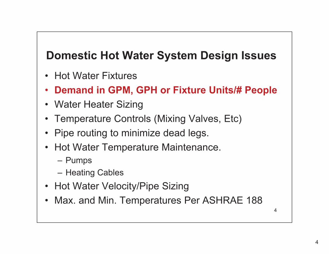
Domestic Hot Water System Design Issues
• Hot Water Fixtures• Demand in GPM, GPH or Fixture Units/# People• Water Heater Sizing• Temperature Controls (Mixing Valves, Etc)• Pipe routing to minimize dead legs.• Hot Water Temperature Maintenance.
– Pumps– Heating Cables
• Hot Water Velocity/Pipe Sizing• Max. and Min. Temperatures Per ASHRAE 188
2

3
Hot Water Usage Fixtures• Bathtub• Shower• Tub/Shower• Kitchen Sink• Sink• Lavatory• Clothes Washer• Dishwasher• HW Hose Station 3
4
Domestic Hot Water System Design Issues
• Hot Water Fixtures• Demand in GPM, GPH or Fixture Units/# People• Water Heater Sizing• Temperature Controls (Mixing Valves, Etc)• Pipe routing to minimize dead legs.• Hot Water Temperature Maintenance.
– Pumps– Heating Cables
• Hot Water Velocity/Pipe Sizing• Max. and Min. Temperatures Per ASHRAE 188
4

5
Most manufacturers have sizing guides
• GPM flow rates• Gallons per hour flow rate based on input
of building type, fixture types and fixture quantities.
• Fixture Unit Values• Number of people in a residential
application.
5

6
Per Person Sizing Method
6

7
Domestic Hot Water System Design Issues
• Hot Water Fixtures• Demand in GPM, GPH or Fixture Units/# People• Water Heater Sizing• Temperature Controls (Mixing Valves, Etc)• Pipe routing to minimize dead legs.• Hot Water Temperature Maintenance.
– Pumps– Heating Cables
• Hot Water Velocity/Pipe Sizing• Max. and Min. Temperatures Per ASHRAE 188
7

8
Domestic Hot Water System Design Issues
• Hot Water Fixtures• Demand in GPM, GPH or Fixture Units/# People• Water Heater Sizing• Temperature Controls (Mixing Valves, Etc)• Pipe routing to minimize dead legs.• Hot Water Temperature Maintenance.
– Pumps– Heating Cables
• Hot Water Velocity/Pipe Sizing• Max. and Min. Temperatures Per ASHRAE 188
8

9
Domestic Hot Water System Design Issues
• Hot Water Fixtures• Demand in GPM, GPH or Fixture Units/# People• Water Heater Sizing• Temperature Controls (Mixing Valves, Etc)• Pipe routing to minimize dead legs.• Hot Water Temperature Maintenance.
– Pumps– Heating Cables
• Hot Water Velocity/Pipe Sizing• Max. and Min. Temperatures Per ASHRAE 188
9

10
Domestic Hot Water System Design Issues
• Hot Water Fixtures• Demand in GPM, GPH or Fixture Units/# People• Water Heater Sizing• Temperature Controls (Mixing Valves, Etc)• Pipe routing to minimize dead legs.• Hot Water Temperature Maintenance.
– Pumps,– Heating Cables
• Hot Water Velocity/Pipe Sizing• Max. and Min. Temperatures Per ASHRAE 188
10

11
Domestic Hot Water System Design Issues
• Hot Water Fixtures• Demand in GPM, GPH or Fixture Units/# People• Water Heater Sizing• Temperature Controls (Mixing Valves, Etc)• Pipe routing to minimize dead legs.• Hot Water Temperature Maintenance.
– Pumps– Heating Cables
• Hot Water Velocity/Pipe Sizing• Max. and Min. Temperatures Per ASHRAE 188
11
12
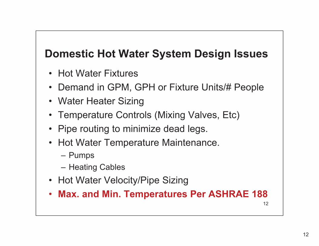
Domestic Hot Water System Design Issues
• Hot Water Fixtures• Demand in GPM, GPH or Fixture Units/# People• Water Heater Sizing• Temperature Controls (Mixing Valves, Etc)• Pipe routing to minimize dead legs.• Hot Water Temperature Maintenance.
– Pumps– Heating Cables
• Hot Water Velocity/Pipe Sizing• Max. and Min. Temperatures Per ASHRAE 188
12

13
Water Heaters
Copyright: Ron George 2010 13

14
Copyright: Ron George 2010 14
Water Heaters

15
Copyright: Ron George 2010 15
ASSE 1016 shower valves
310
3000 40007000

16
Copyright: Ron George 2010 16802 801 805
ASSE 1017 Master Thermostatic Mixing Valves
61
66 67

17
Copyright: Ron George 2010 17
ASSE 1070 Point-of-use Temperature Limiting Valves
310516
570
TMM1070

18
Copyright: Ron George 2010 18
ASSE 1071 Emergency Shower Valves
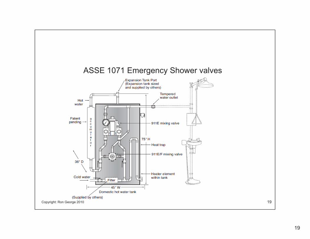
19
Copyright: Ron George 2010 19
ASSE 1071 Emergency Shower valves

20
Circulating Pumps
Copyright: Ron George 2010 20
Residential and Light Commercial Circulators� Wet Rotor Circulators�Closed impeller design improves operating efficiency
�Easily handles dirty water conditions�Rugged, compact design�Close-coupled dry motor�Permanently lubricated Sealed precision bearings�Quiet operations in hydronic, radiant and geothermalheating and cooling systems�Available in cast iron and bronze pump body

21
Copyright: Ron George 2010 21
Glass Lined Steel TanksWater Storage Tanks•Insulation and Topcoat (PDF)•Chilled Water Buffer Tanks (PDF)•Air Eliminator Tanks (PDF)•Solar Tanks
Hot Water Generators • Specifications• Performance Ratings
•Indirect Water Heaters
General Process Tanks • Air Receivers • Boiler Blow-Off Tanks • Surge Tanks • All Purpose Storage Tanks
•Chemical Mixers, Reactors & Storage Vessels•Stainless Steel Tanks
Pipes and Fittings•Reglassing Services•Skid Mounted Systems•Linings Ultonium•Ultonium II •Epoxy •Niles Steel Shield •Sludge Block •Specifications •Sparge-a-tron 2000

22
Copyright: Ron George 2010 22
Thermometers, Gauges, Accessories

23
Copyright: Ron George 2010 23
Expansion Joints & Loops

24
Copyright: Ron George 2010 24
Flow Control/Balancing Valves

25
Copyright: Ron George 2010 25
Chimneys Not PVC flues

26
Copyright: Ron George 2010 26
Steam Control Valves
27
Copyright: Ron George 2010 27
The following slides address scald injuries related to domestic hot water System problems.
These slides show why it is important to design a domestic hot water system Properly to prevent scalding.
Domestic Hot Water Systems

28
Copyright: Ron George 2010 28
• Scalding can occur when the delivery temperaturesexceed 120 degrees F.
• Thermal Shock can occur in several ways. One way is if the fixtures are too far from water heater with no temperature maintenance system or if there is HW Recirculation Pump failure a sudden burst of HW can reach fixtures after a period of use. (Close Apts/Recent use)
• Thermal Shock can occur if there is a sudden change in pressure between hot & cold water supplies to a fixture & there is no Safety Type Shower Valve installed.
• A Combination Press. Balance/Thermostatic valveprotects against both temperature and pressure fluctuations.
• Thermal shock often leads to slip & fall injuries.
Domestic Hot Water System Problems

29
Copyright: Ron George 2010 29
Scald Injuries
• Often a Scald Victim is left scarred for life and traumatized by their burns.
• The pain is continuous and the psychological effects last their lifetime.
30
Copyright: Ron George 2010 30
Definition - Thermal Shock• Thermal Shock occurs when there is a
pressure or temperature disturbance in the piping system that will cause a sudden change in the shower temperature. The sudden change in the shower temperature can cause a slip and fall injury that an lead to broken bones or a head injury from a fall. Sometimes the bather will grab the temperature controls on the way down and it can lead to a scalding incident.
31
Copyright: Ron George 2010 31
Definition - Scalding
• Scalding can occur when the skin is exposed to temperatures in excess of 120 degrees Fahrenheit. Scalding can occur in varying degrees based on the temperature of the water and the exposure time.
32
32
Thermal Shock & Scalding ConcernsThere is a Major Concern in Older Homes with Two-Handled & Non-compensating Shower Controls.
• “Thermal shock” and “scalding” is a health and safety issue related to the restriction of flow at shower heads with non-compensating type shower valves. This is a matter of Physics.

33
33
Why should we be concerned about Scald Burns ?
• Scald Burns are extremely painful and life altering injuries that can be deadly!
• We must take every precaution to prevent the increased risk of thermal shock and scalding. If there is any possibility of an increased risk we must make corrections to the plumbing system or warn consumers and the building owner of the potential increased risk of scalding.
• Warnings should be included on products, packaging and in installation and maintenance literature with low flow showerheads (Below 2.5 GPM)
• Ignoring the problem and Increasing the risk of thermal shock and scalding should not be allowed.

34
34
Scald Burn to BackHot Water Burns Like Fire

35
35
Infant with scald burns
Hot Water Burns Like Fire

36
36
Elementary school child with scald burnsHot Water Burns Like Fire

37
37
Amputation of big toe because of dead tissue from scald burn from a Bathtub Faucet
Hot Water Burns Like Fire

38
38
Scald Burn/Death (Small child in a Kitchen Sink)
Hot Water Burns Like Fire

39
39
Contraction of skin grafts and scars during healing can cause deformities from swelling.

40
40
Shower Scald Burn to Face, Chest and Body
Hot Water Burns Like Fire

41
41
Shower Scald Burn to Face, Chest and Body
Hot Water Burns Like Fire

42
42
Scald Burn to teenager’s shoulder

43
43
Scald Burn to an adult’s thigh
Water Line

44
44
Scald burnScald burn on an adultfrom a shower
Hot Water Burns Like Fire

45
45
Scald burn
8-year-old boy with scald burnsfrom a shower
46
46
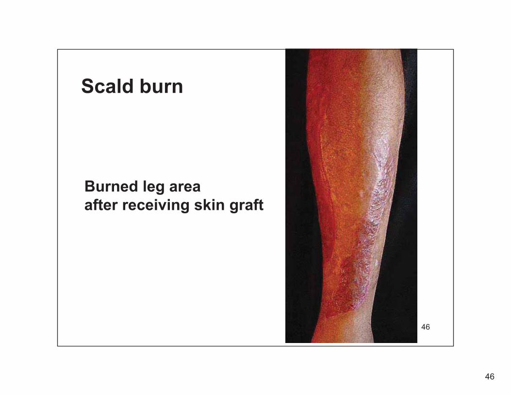
Scald burn
Burned leg area after receiving skin graft

47
47
Scald burn to hand

48
48
Skin graftdonor area

49
Hot Water Burns Like Fire
49

50
Hot Water Burns Like Fire
50

51
Hot Water Burns Like Fire
51

52
Hot Water Burns Like Fire
52

53
Hot Water Burns Like Fire
53

54
54
Scald Injuries
• Often a Scald Victim is left scarred for life and traumatized by their burns, the ongoing pain and the stigma of their Burns causing them to look awkward when in Public and causes lifelong psychological issues.

55
55
Scald Burns and low flow shower heads
• Scald Burns are extremely painful and life altering injuries!
• We must take every precaution to prevent the potential to increase the risk of thermal shock and scalding. If there is any possibility of an increased risk we must warn consumers and building owner of the potential increased risk of scalding.
• Warnings must be included on products, packaging and in installation and maintenance literature with low flow showerheads (Below 2.5 GPM)
• Ignoring the problem and Increasing the risk of thermal shock and scalding should not be allowed.

56
Copyright: Ron George 201056
What could have prevented these scald burns?1. A Thermostatic mixing valve with the proper piping
arrangement.
2. Setting the Temperature limit stop on an ASSE 1016 Pressure or Temperature Compensating type Shower Valve.
3. A Temperature Actuated Flow Reduction (TAFR) device that conforms to ASSE 1062. It shuts down the flow of water if the temperature flowing through the device exceeds 115 F - 117 F.

57
57
• No manufacturer can build a low-flow shower head that will not be susceptible to thermal shock and scalding IF,
1. The Shower Head is connected to a two-handled or non-compensatingshower valve
2. It is connected to an ASSE 1016 shower valve that has not been designed and tested for low flows.
Thermal Shock & Scalding Concerns

58
58
Thermal Shock & Scalding Concerns in older homes
• Many water conservation programs and other utility sponsored water conservation programs are ignoring the dangers of existing Non-Compensating shower valves which make up over 50% of all existing installations.
• Validation is needed through testing low flow shower heads with shower valves.

59
59
Thermal Shock & Scalding Concerns• Currently ALL recent low-flow showerhead testing
for water conservation programs has been done with newer code compliant buildings (hotels and
dormitories) with code compliant compensating type shower valves and engineered plumbing system installations. (In systems with properly sized water heaters, ASSE 1016 shower valves and in most cases with ASSE 1017 Master mixing valves)
• Real world risk of thermal shock and scalding do exist in the test buildings. A significant portion of existing buildings have older non-code compliant fixtures..

60
Copyright: Ron George 2010 60
Scalding is one of the largest areas for litigation in plumbing & mechanical systems.
The codes have minimal requirements for hot water system sizing, controls, safety devices and system design.
This often leaves dangerous hot water system sizing, temperature settings and installations to people without proper training or guidance with tragic results.
Domestic Hot Water Systems
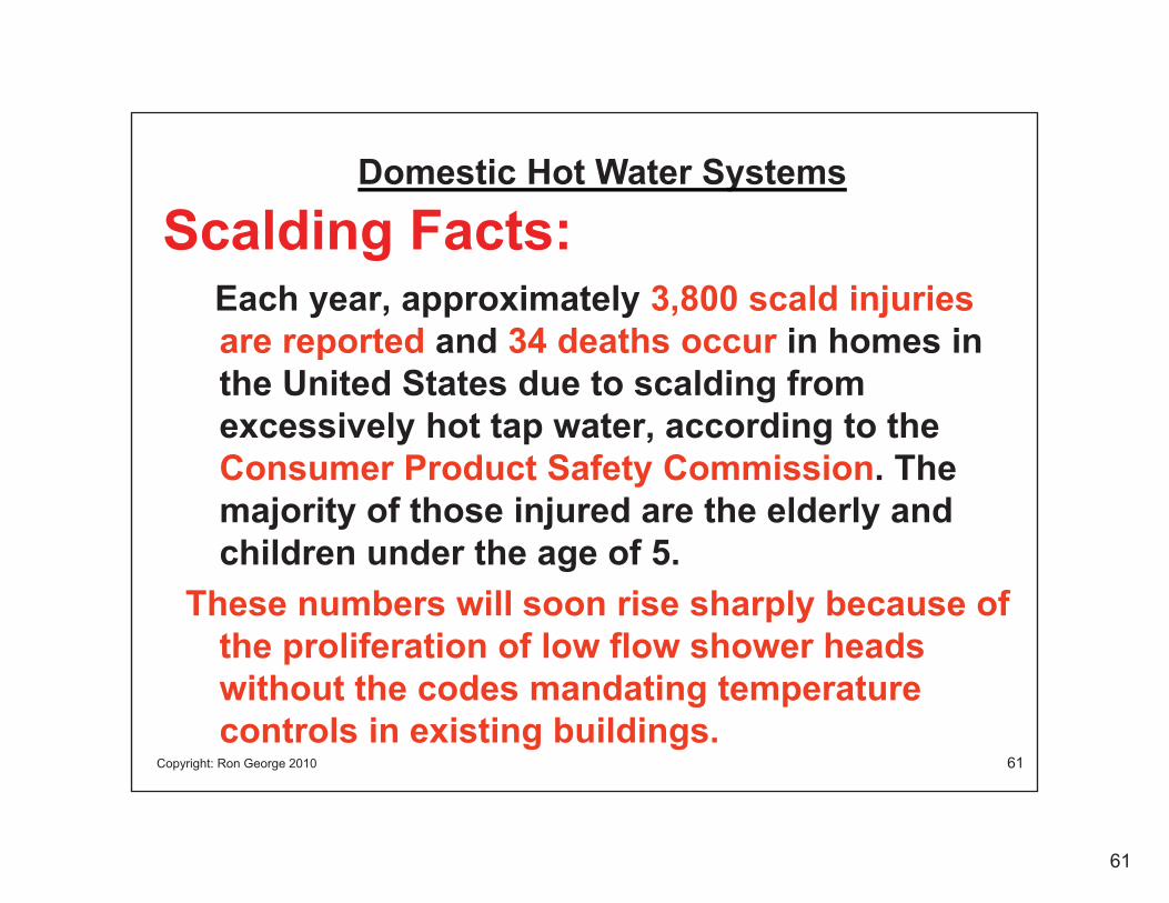
61
Copyright: Ron George 2010 61
Scalding Facts:Each year, approximately 3,800 scald injuries are reported and 34 deaths occur in homes in the United States due to scalding from excessively hot tap water, according to the Consumer Product Safety Commission. The majority of those injured are the elderly and children under the age of 5.
These numbers will soon rise sharply because of the proliferation of low flow shower heads without the codes mandating temperature controls in existing buildings.
Domestic Hot Water Systems

62
Copyright: Ron George 2010 62
Scalding Facts:– Severe damage occurs to adult skin instantly when it is
exposed to hot water over 151 Degrees Fahrenheit151 F + = Immediate scald burn with irreversible injuries
– Severe damage to an adult's skin can occur in 30 seconds whenexposed to water temperatures at 130 degrees Fahrenheit.
130 F = 30 Seconds plus or minus until irreversible scald injury occurs depending on the skin thickness.
– It takes up to five minutes for a severe burn injury to occur if the hot water system is distributed at the recommended maximum HW Temperature of 120 Fahrenheit, allowing people time to react and remove themselves from the hot water.
120 F = 5 minutes Plus or minus
Domestic Hot Water Systems
63
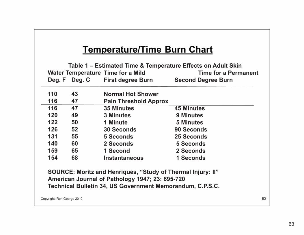
Copyright: Ron George 2010 63
Table 1 – Estimated Time & Temperature Effects on Adult SkinWater TemperatureDeg. F Deg. C
110 43116 47116 47120 49122 50126 52131 55140 60159 65154 68
SOURCE: Moritz and Henriques, “Study of Thermal Injury: II”American Journal of Pathology 1947; 23: 695-720Technical Bulletin 34, US Government Memorandum, C.P.S.C.
Time for a Mild Time for a PermanentFirst degree Burn Second Degree Burn
Normal Hot ShowerPain Threshold Approx35 Minutes 45 Minutes3 Minutes 9 Minutes1 Minute 5 Minutes30 Seconds 90 Seconds5 Seconds 25 Seconds2 Seconds 5 Seconds1 Second 2 SecondsInstantaneous 1 Seconds
64
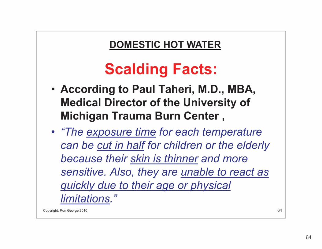
Copyright: Ron George 2010 64
Scalding Facts:• According to Paul Taheri, M.D., MBA,
Medical Director of the University of Michigan Trauma Burn Center ,
• “The exposure time for each temperature can be cut in half for children or the elderly because their skin is thinner and more sensitive. Also, they are unable to react as quickly due to their age or physical limitations.”
DOMESTIC HOT WATER

65
Copyright: Ron George 2010 65
Water Heater Thermostat AccuracyA common source of the scalding problem is many homeowners, code officials and industry professionals think the dial on a water heater controls the outlet temperature of the water heater. The water heater thermostat or burner control thermostat does NOT accurately control the outlet temperature of a water heater. There must be additional temperature controls downstream of the water heater to prevent scalding.
Ron George
66
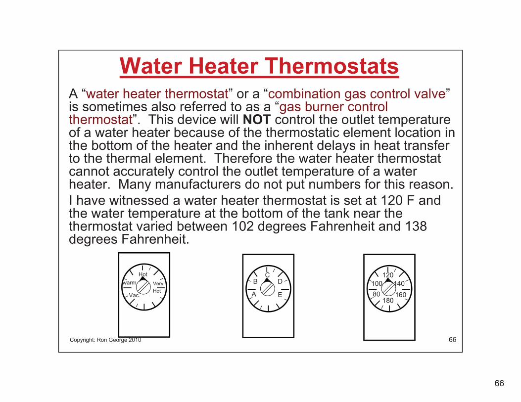
Copyright: Ron George 2010 66
Water Heater ThermostatsA “water heater thermostat” or a “combination gas control valve” is sometimes also referred to as a “gas burner control thermostat”. This device will NOT control the outlet temperature of a water heater because of the thermostatic element location in the bottom of the heater and the inherent delays in heat transfer to the thermal element. Therefore the water heater thermostat cannot accurately control the outlet temperature of a water heater. Many manufacturers do not put numbers for this reason.I have witnessed a water heater thermostat is set at 120 F and the water temperature at the bottom of the tank near the thermostat varied between 102 degrees Fahrenheit and 138 degrees Fahrenheit.
D
E
B
A
C
Hotwarm
Vac.
Hot
180
140160
10080
120Very

67
Copyright: Ron George 2010 67
Water Heater Thermostat Construction• Robertshaw – Two Buttons on Top
• White-Rodgers – One Button on Top
• The boundary layer of water, the tube wall and the void space all contribute to a delay in temperature sensing.
Void SpaceThermostatic Element
Tube Wall
• Accuracy + - 6 to 18 F from Set Point• Average + - 11 to 15 F from Set Point
Combination Gas Control Valve
Boundary Layer

68
Copyright: Ron George 2010 68
X-Ray WH Thermostat

69
Copyright: Ron George 2010 69
WH Thermostat
Robertshaw (Unitrol)Two KnobsAccuracy = + - 15-18 Deg F
White RodgersOne KnobAccuracy = + - 11-14 Deg F
Combination Gas Control Valves

70
Copyright: Ron George 2010 70
Electric Water Heater Thermostats• Electric Water heater thermostats are typically
manufactured by Emmerson Electric and they sense the temperature of the water by attaching to the outside of the tank wall and reading the water temperature through the tank wall. Again a delay in temperature sensing is from the boundary layer and the tank wall material heat transfer rate.
TANK WALLBOUNDARY LAYER
Heat Transfer Path

71
Copyright: Ron George 2010 71
Electric Water Heater Thermostats
Air Gap Prevents heat transfer which causes overheating

72
Copyright: Ron George 2010 72
HW System Problems
• Problem:The plumbing system is design so that the thermostat setting on Water Heater is relied upon for system temperature controls with no further safety controls downsteam of the water heater.1. Explanation of the Stacking effect2. 11 degrees +- for a 22 degree swing3. Most model code do not allow the thermostat on the water heater to be the final temperature control for a HW system.

73
Copyright: Ron George 2010 73
Water Heater Thermostat Setting• Water Heater Thermostat Setting - Instead of just setting
the thermostat on the water heater to 120 F, A major Midwest University’s Trauma Burn Center recommends that anti-scald mechanical devices such as thermostatic mixing valves be installed near the water heater to mix the hot and the cold water to deliver it at a maximum safe temperature of 120 F. This is especially important when one system supplies hot water to numerous apartments or units.
The Thermostat on a water heater should never be used as the final temperature control for a hot water system.
ASSE 1017 / ASSE 1070 Thermostatic Mixing Valve
Water Heater Gas Control Valve

74
Copyright: Ron George 2010 74
Water Heater Gas Control Valve
A Water heater Thermostat should not be used as the final temperature control for the domestic hot water system!
The temperature swing from “burner on” to “burner off” can be as much as 30 degrees F.
Misleading Manufacturer Literature leads users to believe thay can control the outlet temperature of a water heater with the burner control thermostat

75
Copyright: Ron George 2010 75
T
HOT WATER RISES TO THE TOP OF AN UNCIRCULATED TANK DURING PERIODS OF NON-USE.
COLD WATER IS MORE DENSE AND STAYS AT THE BOTTOM OF THE TANK.
THERE CAN BE A SIGINIFICANTDIFFERENCE IN TEMPERATURE FROM THE TOP OF THE TANK TO THE BOTTOM.
THE TOP PORTION OF THE TANK CAN BE EXTREMELY HOT.
THE THERMOSTAT CAN VARY AS MUCH AS 15 - 18 DEGREES PLUS OR MINUS FROM THE SET POINT
THE BOTTOM PORTION IS NOT HOT ENOUGH TO BE A USEABLE TEMPERATURE.
163 F out
WH Set at 125 F
Up to 163 F
34-850 F
143 F = OFF125 F Set Pt 107 F = ON
153
163
158
143
148
Water Heater Storage Temp’sThe “Stacking Effect” or “Thermal Layering” in
Un-circulated Storage Type Water Heaters
Burner On 105 F
T-Stat Set Point 120 F
Burner Off 135 F

76
Copyright: Ron George 2010 76
Water Heater Burner Control at 120 F
120
135
105
Burner OFF
T-Stat Set Temp = 120 F
Actual Temps at T-Stat vary between 105 F and 135 F
Burner OFF
Burner ON
Burner OFF
Burner ONBurner ON
Tem
p Fl
uctu
atio
n F.
Time
With HW rising to the top of the heater and multiple short draws of HW the temp can significantly increase above 135 F

77
Copyright: Ron George 2010 77
Water Heater Burner Control at 140 F
140
155
125
Burner OFF
T-Stat Set Temp = 140 F
Actual Temps at T-Stat vary between 125 F and 155 F
Burner OFF
Burner ON
Burner OFF
Burner ONBurner ON
Tem
p Fl
uctu
atio
n F.
Time
With HW rising to the top of the heater and multiple short draws of HW the temp can significantly increase above 155 F
78
Copyright: Ron George 2010 78
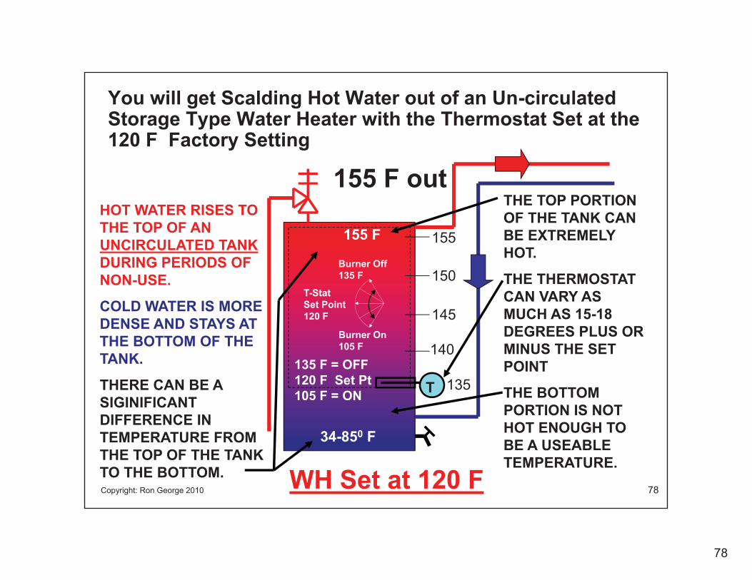
You will get Scalding Hot Water out of an Un-circulated Storage Type Water Heater with the Thermostat Set at the 120 F Factory Setting
T
HOT WATER RISES TO THE TOP OF AN UNCIRCULATED TANKDURING PERIODS OF NON-USE.
COLD WATER IS MORE DENSE AND STAYS AT THE BOTTOM OF THE TANK.
THERE CAN BE A SIGINIFICANTDIFFERENCE IN TEMPERATURE FROM THE TOP OF THE TANK TO THE BOTTOM.
THE TOP PORTION OF THE TANK CAN BE EXTREMELY HOT.
THE THERMOSTAT CAN VARY AS MUCH AS 15-18 DEGREES PLUS OR MINUS THE SET POINT
THE BOTTOM PORTION IS NOT HOT ENOUGH TO BE A USEABLE TEMPERATURE.
135 F = OFF120 F Set Pt 105 F = ON
155 F out
WH Set at 120 F
Burner On 105 F
T-Stat Set Point 120 F
155 F
34-850 F
145
155
150
135
140
Burner Off 135 F

79
Copyright: Ron George 2010 79
With “Thermal Layering” or Stacking, The water temperature at the top of the tank can be significantly higher that the water temperature at the thermostat level.
T
HOT WATER RISES TO THE TOP OF AN UNCIRCULATED TANK
Short draws of hot watercause the thermostat to sense the cold water at the bottom of the tank.
The burner comes on and even though the water at the top of the heater is very hot.
THE TOP PORTION OF THE TANK CAN BE EXTREMELY HOT.
THE THERMOSTAT CAN VARY AS MUCH AS 15-18 DEGREES PLUS OR MINUS THE SET POINT
Multiple short draws of HW cause CW to enter the bottom of the heater and it causes the burner to come one each time, overheating HW at the top.
135 F = OFF120 F Set Pt 105 F = ON
155 F out
WH Set at 120 F
Burner On 105 F
T-Stat Set Point 120 F
155 F
34-850 F
145
155
150
135
140
Burner Off 135 F

80
Copyright: Ron George 2010 80
T
HOT WATER RISES TO THE TOP OF AN UNCIRCULATED TANK DURING PERIODS OF NON-USE.
COLD WATER IS MORE DENSE AND STAYS AT THE BOTTOM OF THE TANK.
THE BOTTOM 1/3 OF THE TANK CAN HAVE TEMPERATURES IN THE IDEAL GROWTH RANGE FOR BACTERIA.
THE TOP PORTION OF THE TANK CAN BE EXTREMELY HOT.
THE THERMOSTAT CAN VARY AS MUCH AS 15 - 18 DEGREES PLUS OR MINUS FROM THE SET POINT FOR THIS REASON THE THERMOSTAT CANNOT BE RELIED UPON TO CONTROL THE OUTLET TEMPERATURE OF A WATER HEATER.
THE BOTTOM PORTION IS NOT HOT ENOUGH TO BE A USEABLETEMPERATURE.
163 F out
WH Set at 125 F
Up to 163 F
34-85 0F CW IN
143 F = OFF125 F Set Pt 107 F = ON
153
163
158
143
148Burner On 105 F
T-Stat Set Point 120 F
Burner Off 135 F
Water Heater Storage Temp’sThe “Stacking Effect” or “Thermal Layering” in
Un-circulated Storage Type Water Heaters

81
Copyright: Ron George 2010 81
Stacking
The following is language from a water heater installation & Maintenance manual:
Stacking occurs when a series of short draws of hotwater (3 gallons or less) are taken from the water heatertank. This causes increased cycling of the heater elementsand can result in increased water temperatures at thehot water outlet. An anti-scald device is recommendedin the hot water supply line to reduce the risk of scaldinjury.
The Anti-Scald Device they are referring to is an ASSE 1017 or ASSE 1070 thermostatic mixing valve

82
Copyright: Ron George 2010 82
Note:You cannot set a water heater at 120 F degrees and expect to accurately control the outlet temperature of the water heater for purposes of preventing scalding!
83
Copyright: Ron George 2010 83
Most Residential Water Heaters are designed to store and deliver hot water at 140 Degrees F. Residential water heater sizing is based on gallons stored in the water heater relative to number of bedrooms. If The thermostat is turned down to minimize the risk of scalding, the following problems can occur:
1. Less hot water is available for peak hot water loads.
2. Condensation can form in the flues causing corrosion of the heater.
3. When Hot Water runs out users often turn the thermostat back up, higher than the original setting. This increases the risk of scalding.
4. When the water heater thermostat is adjusted, the maximum temperature limit stops on all ASSE 1016 shower valves must be readjusted most of the time this is not done. This increases the risk of scalding.

84
Copyright: Ron George 2010 84
Install a Thermostatic Mixing Valve to:
• Prevent temperature swings in the hot water distribution system
• Prevent scalding and
• Prevent Legionellae Bacteria growth in the hot water tank.

85
Copyright: Ron George 2010 85
How Do We Control the Temperature Swings?Use ASSE 1017 Thermostatic Mixing Valves at the Water Heater!
120 F34 - 85 F
T
143 F to 163 F
143 F = OFF125 F Set Pt 107 F = ON
34-850 F
HOT WATER RISES TO THE TOP OF AN UNCIRCULATED TANKDURING PERIODS OF NON-USE.
COLD WATER IS MORE DENSE AND STAYS AT THE BOTTOM OF THE TANK.
THERE CAN BE 120 DEGREE DIFFERENCE IN TEMPERATURE FROM THE TOP OF THE TANK TO THE BOTTOM.
THE TOP PORTION OF THE TANK CAN BE EXTREMELY HOT.
THE THERMOSTAT CAN VARY AS MUCH AS 15-18 DEGREES PLUS OR MINUS THE SET POINT
THE BOTTOM PORTION IS NOT HOT ENOUGH TO BE A USEABLE TEMPERATURE.
ASSE 1017 Therm. Mixing Valve
143 -163 F HW

86
Copyright: Ron George 2010 86
Problems with Recirc piping and mixing valvesUse ASSE 1017 Thermostatic Mixing Valves at the Water Heater!
34 - 85 F
T
135 F to 155 F
155 F = OFF140 F Set Pt 125 F = ON
100-1100 F
ASSE 1017 Therm. Mixing Valve
125 -155 F HW
HW CIRC PUMP
120-155 F
34 - 85 F
Flow only from the hot water side of the Mixing Valve during periods of non use.

87
Copyright: Ron George 2010 87
Proper Recirc Pump Piping with a Mixing ValveUse ASSE 1017 Thermostatic Mixing Valves at the Water Heater!
100-110 F
34 - 85 F
T
135 F to 155 F
155 F = OFF140 F Set Pt 125 F = ON
100-1100 F
ASSE 1017 Therm. Mixing Valve
125 -155 F HW
SPLIT RETURN AFTER CIRC PUMP TO PROVIDE FLOW TO BOTH SIDES OF THE MIXING VALVE. CONNECT TO: 1. WH CW INLET 2. MIXING VA. CW INLET
120 F
HW CIRC PUMP

88
88
How To Control the HW Temperatures?
CW
ASSE 1016 / CSA B125.1Press(P).,Temp(T) or Comb. (P) & (T)Type Shower Valve W/ Max. Temp. Limit
T
HW 140 F
40 F
155 F
120 F
ASSE 1017 / CSA B125.3Master Thermostatic Mixing Valve
ASSE 1070Point-of-use Thermostatic Mixing Valve
ASSE 1062Temperature Actuated Flow Reduction Device
TW 120 F
Sink/ Lav
Tub/ Shower
Tub
By: Ron George
Shower

89
Copyright: Ron George 2010 89
Why use Thermostatic Mixing Valves?
1. To accurately and safely deliver hot water to points of use.
2. Because water heaters cannot deliver a consistently safe HW supply temperature.
3. Because hot water must be storage above 135 to 140 F to prevent Legionella bacteria growth.
4. To prevent flue gases from condensing in low temperature, gas fired water heaters

90
Copyright: Ron George 2010 90
Water Heater Burner Control
120
135
105
Burner OFF
Thermostatic Mixing Valve on WH outlet pipe Temp = 120 F Plus or Minus 3 to 5 F
HW Temps at T-Stat of Water Heater vary between 105 F and 135 F
Burner OFF
Burner ON
Burner OFF
Burner ONBurner ON
Tem
p Fl
uctu
atio
n F.
Time
T-Stat Set Temp = 120 F

91
91
The Real World – Old Hot Water Systems
• Over 50% have no Master Mixing Valve (ASSE 1017)• Over 50% have no Temperature or Pressure
Compensating Shower Valve (ASSE 1016)• Over 50% have no means to limit the maximum hot
water temperature with temperature limit stops.• Many have no ability for old water heaters to
maintain HW capacity when they get scaled up with lime/calcium deposits.
• Many systems have the thermostat adjusted to a hotter storage temperature to compensate for a slow recovery rate in hard water areas.
92
92
The Real World – Old Hot Water Systems
• Many systems have no ability to address Legionellae bacteria when the water heater temperatures are turned down to address scalding concerns.
• Most systems have no ability to satisfy the peak hot water demand when the water heater thermostat is turned down to address scalding concerns.
• Most systems have no ability to address pressure imbalances in the water distribution system when there is a non-compensating shower control valve installed.

93
93
Thermal Shock & Scalding Concerns
• Over 50% of existing installations, Those with the greatest potential for scalding and thermal shock are not being tested with low flow shower heads!

94
94
Thermal Shock & Scalding Awareness
• WARNINGS ARE NEEDED ON LOW FLOW SHOWER HEADS becausethe RISK of scalding increases exponentially with the reduction in flow at the shower head!

95
95
Thermal Shock & Scalding Awareness
• A major water conservation program has decided not to require warnings on the shower heads, the packaging or the literature for low flow shower heads for fear that warnings would detract from marketing efforts.
• We must warn the unsuspecting public of the scald hazards!
96
96
Thermal Shock & Scalding Awareness• ASSE Press Releases?
• ASSE HW Scald Awareness Committee prepared a White Paper/Report. Publicize the issue.
• Work with ASME and ASSE Shower Head and shower valve standards committees to match the flows in the standards and develop a way to match products.

97
97
Thermal Shock & Scalding Awareness• Work to get ASSE and ASME to publish flow
rates on the products to be able to match the flows. Is there is another way to accomplish this.
• Does ASSE adjust the 1016 standard to Mandate the shower head flow rate matches the shower valve flow rate?
• We need “Warnings” on the products about the dangers of non-compensating control valves.

98
98
Matched Flows are Needed for Shower Head and Shower Valve Product Standards• The ASME A112 Standard for Shower
Heads Requires Shower Heads to Be Flow Tested at 80 PSI(A pressure which the shower head will never be exposed to because 80 psi is the maximum pressure allowed in the plumbing system. During flow the residual pressure is likely to be 60 PSI or less. The ASME shower head flowing test pressure does not take into account the friction loss in the piping system.

99
99
Matched Flows are Needed for Shower Head and Shower Valve Product Standards
• The ASSE 1016 Standard tests the shower valves at 45 PSI.
100
100
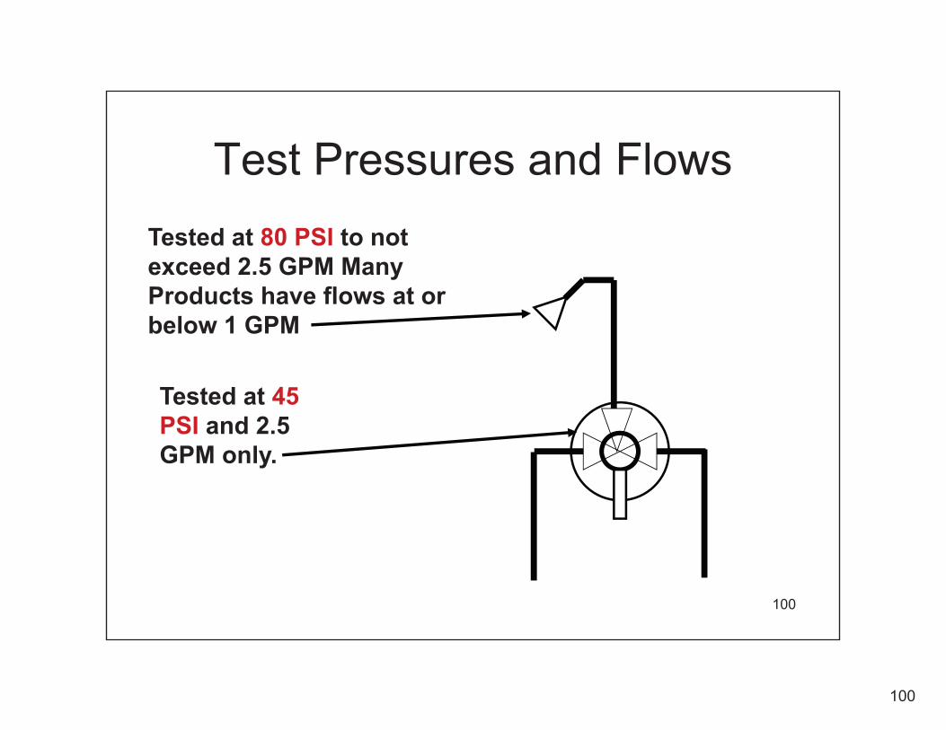
Test Pressures and Flows
Tested at 45PSI and 2.5 GPM only.
Tested at 80 PSI to not exceed 2.5 GPM Many Products have flows at or below 1 GPM

101
101
Definition:
• Non-Compensating Shower Control Valve– A shower valve that does not compensate for changes in pressure or temperature. This would include: Two-handled shower valves andolder style Single-handle shower valves without a pressure balancing/compensating component or a thermostatic compensating component. It is estimated that over 50 percent of all existing homes have non-compensating shower valves.

102
102
Two-Handled Shower Valves do not prevent:
Thermal Shock or Scalding
It is estimated that close to 50% of all existing showers have two-handle non-compensating shower controls.

103
103
Two-Handled Shower Valves do not prevent:
Thermal Shock or Scalding
When an existing shower head is replaced with a low flow shower head, the low flow shower head creates a flow restriction in the shower head riser. Pressure disturbances in the system become the path of least resistance when another nearby fixture is opened.
Flow Restrictor Type Shower Head
Flow Restrictor
When a near-by CW fixture is used HW will crossover through the valve and flow to the path of least resistance.

104
104
Existing Non-Compensating Installations
Older Housing Stock
• The non-compensating style of shower control is probably the most common shower valve installed in older homes in the US. (About50% or more)
• Two-handled shower valves do not compensate for changes in incoming pressure or temperature as required by the model plumbing codes.
• These types of valves were generally installed prior to 1978 when codes required anti-scald valves for new construction.
• What testing is there for existing Installations?

105
Pressure Balancing Shower Valves
105

106
Non-Pressure Balancing Shower Valve
106

107
Pressure Balancing Shower valve
107Pressure Balancing Spool

108
Thermostatic shower valves
108
109
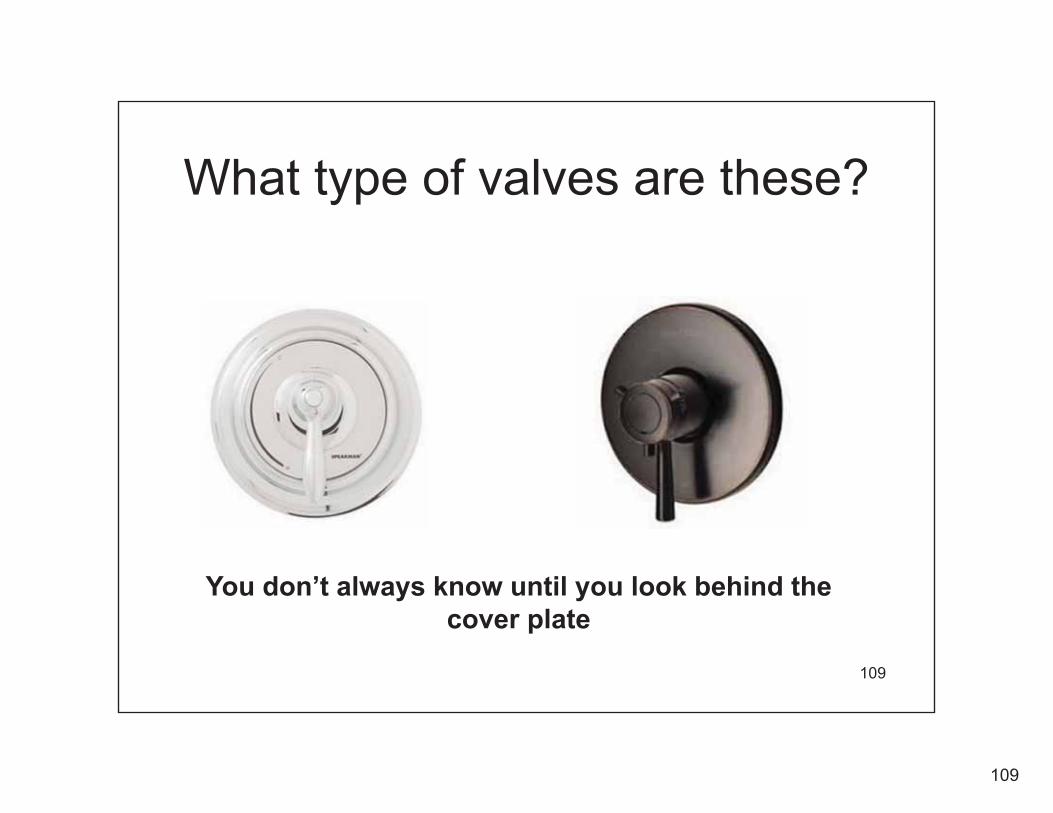
What type of valves are these?
109
You don’t always know until you look behind the cover plate

110
110
Pressure Balancing ValveTW
CW HW

111
111
Pressure Balancing ValveTW
CW HW
If the incoming water temperature changes this type of valve does not have the ability to sense temperature and compensate for incoming water temperaturechanges
Limit Stop Set Screw

112
112
The Thermostatic Shower ValvesTwo kinds of actuators
2. Liquid Parafin Wax Filled Capsule Principle
This Design is like a clock spring. It has poor torque & it is susceptible to sticking because of scale & sediment build-up on the coil and shuttle. Low torque requires greater manuf’g tolerances.
Only a few pounds of force to move a mixing valve shuttle.
Hundreds of pounds of force to move a mixing valve shuttle.
1. Bi-Metal Principle

113
113
Thermostatic Valves with Parafin Wax offer swift reaction and a powerful stroke

114
114
Scald Burns• Scald Burns are extremely painful and life
altering injuries that can be deadly!• We must take every precaution to prevent the increased risk
of thermal shock and scalding. If there is any possibility of an increased risk we must make corrections to the plumbing system or warn consumers and the building owner of the potential increased risk of scalding.
• Warnings should be included on products, packaging and in installation and maintenance literature with low flow showerheads (Below 2.5 GPM)
• Ignoring the problem and Increasing the risk of thermal shock and scalding should not be allowed.

115
115
The “Stacking Effect” inUn-circulated Water Heaters
T
Up to 165 F
HOT WATER RISES TO THE TOP OF AN UNCIRCULATED TANKDURING PERIODS OF NON-USE.
COLD WATER IS MORE DENSE AND STAYS AT THE BOTTOM OF THE TANK.
THERE CAN BE A SIGINIFICANTDIFFERENCE IN TEMPERATURE FROM THE TOP OF THE TANK TO THE BOTTOM.
THE TOP PORTION OF THE TANK CAN BE EXTREMELY HOT.
THE THERMOSTAT CAN VARY AS MUCH AS 15-18 DEGREES PLUS OR MINUS THE SET POINT
THE BOTTOM PORTION IS NOT HOT ENOUGH TO BE A USEABLE TEMPERATURE.
34-850 F
143 F = OFF125 F Set Pt 107 F = ON
165 F out
Set at 125 F

116
116
The “Stacking Effect” inUn-circulated Water Heaters
T
up to 155 F
HOT WATER RISES TO THE TOP OF AN UNCIRCULATED TANKDURING PERIODS OF NON-USE.
COLD WATER IS MORE DENSE AND STAYS AT THE BOTTOM OF THE TANK.
THERE CAN BE A SIGINIFICANTDIFFERENCE IN TEMPERATURE FROM THE TOP OF THE TANK TO THE BOTTOM.
THE TOP PORTION OF THE TANK CAN BE EXTREMELY HOT.
THE THERMOSTAT CAN VARY AS MUCH AS 15-18 DEGREES PLUS OR MINUS THE SET POINT
THE BOTTOM PORTION IS NOT HOT ENOUGH TO BE A USEABLE TEMPERATURE.
34-850 F
135 F = OFF120 F Set Pt 105 F = ON
155 F out
Set at 120 F

117
117
How Do We Control the Temperature Swings?Use ASSE 1017 Thermostatic Mixing Valves at the Water Heater!
120 F34 - 85 F
T
143 F to 163 F
143 F = OFF125 F Set Pt 107 F = ON
34-850 F
HOT WATER RISES TO THE TOP OF AN UNCIRCULATED TANKDURING PERIODS OF NON-USE.
COLD WATER IS MORE DENSE AND STAYS AT THE BOTTOM OF THE TANK.
THERE CAN BE 120 DEGREE DIFFERENCE IN TEMPERATURE FROM THE TOP OF THE TANK TO THE BOTTOM.
THE TOP PORTION OF THE TANK CAN BE EXTREMELY HOT.
THE THERMOSTAT CAN VARY AS MUCH AS 15-18 DEGREES PLUS OR MINUS THE SET POINT
THE BOTTOM PORTION IS NOT HOT ENOUGH TO BE A USEABLE TEMPERATURE.
ASSE 1017 Therm. Mixing Valve
143 -163 F HW

118
118
How Do We Control the Temperature Swings?Circulating hot water return through the heater mixes up the hot water in the tank and stabilizes the hot water temperature!
120 F
34 - 85 F
T
125 F to 155 F
155 F = OFF140 F Set Pt 125 F = ON
1100 F+-
ASSE 1017 Therm. Mixing Valve
125 -155 F HW
HW CIRC PUMP SIZED FOR 10 DEGREE TEMP. DIFFERENCE

119
119
The Device installed here shuts-off the flow of water to a drip when the temperature exceeds 115 to 117 Degrees F (46C to 47C)
Available at: http://www.cashacme.com/prod_thermostatics_HG_TAFR.phpor www.pppinc.net
A cheap solution for non-compensating shower valves.Temperature Actuated Flow Reduction Valve (TAFR)
ASSE-1062

120
120
The Device installed here shuts-off the flow of water to a drip when connected to a 2.5 GPM shower head and the temperature exceeds 115 to 117 Degrees F (46C to 47C)
Available at: http://www.cashacme.com/prod_thermostatics_HG_TAFR.phpor www.pppinc.net
A cheap solution for non-compensating shower valves.Temperature Actuated Flow Reduction Valve (TAFR)
ASSE-1062

121
Copyright: Ron George 2010121
Many Low Flow shower heads 1.5 GPM & below still have a full spray pattern when the ASSE 1062 Device reduces the flow to approx 0.5 GPM.
Available at: http://www.cashacme.com/prod_thermostatics_HG_TAFR.phpor www.pppinc.net
A cheap solution for non-compensating shower valves.
Temperature Actuated Flow Reduction Valve (TAFR) ASSE-1062

122
122
Why use Thermostatic Mixing Valves?
• Safety: Accurately and Safely deliver water to points of use when the water storage temperatures have been increased to:
A) Eliminate legionella incubationB) Deliver water at a safe temperature for
bathing.C) Prevent flue gases from condensing in gas
fired water heaters

123
123
Quotes
“Protection of the Public’s Health and Safety is Non-negotiable!”
Source:
Undersecretary, Department of Environment and Natural Resources, (DENR)
Brigadier General, Francisco Bravo (Philippines)
124
Copyright: Ron George 2010124
Plumbing System Design Including Water Conservation and ReclaimApril 16–20, 2012 Madison, Wisconsin
Hot Water System Design Considerations in High Rise Buildings“Sustainable vs Unsustainable” DesignsInstructor:Ronald L. George, CPD, President, Plumb-Tech Design & Consulting Services LLCWebsite: www.Plumb-TechLLC.com Ph: (734) 322-0225 Cell: (734) 755-1908 EM: [email protected]
College of Engineering Department of Professional Development
125
Copyright: Ron George 2010125
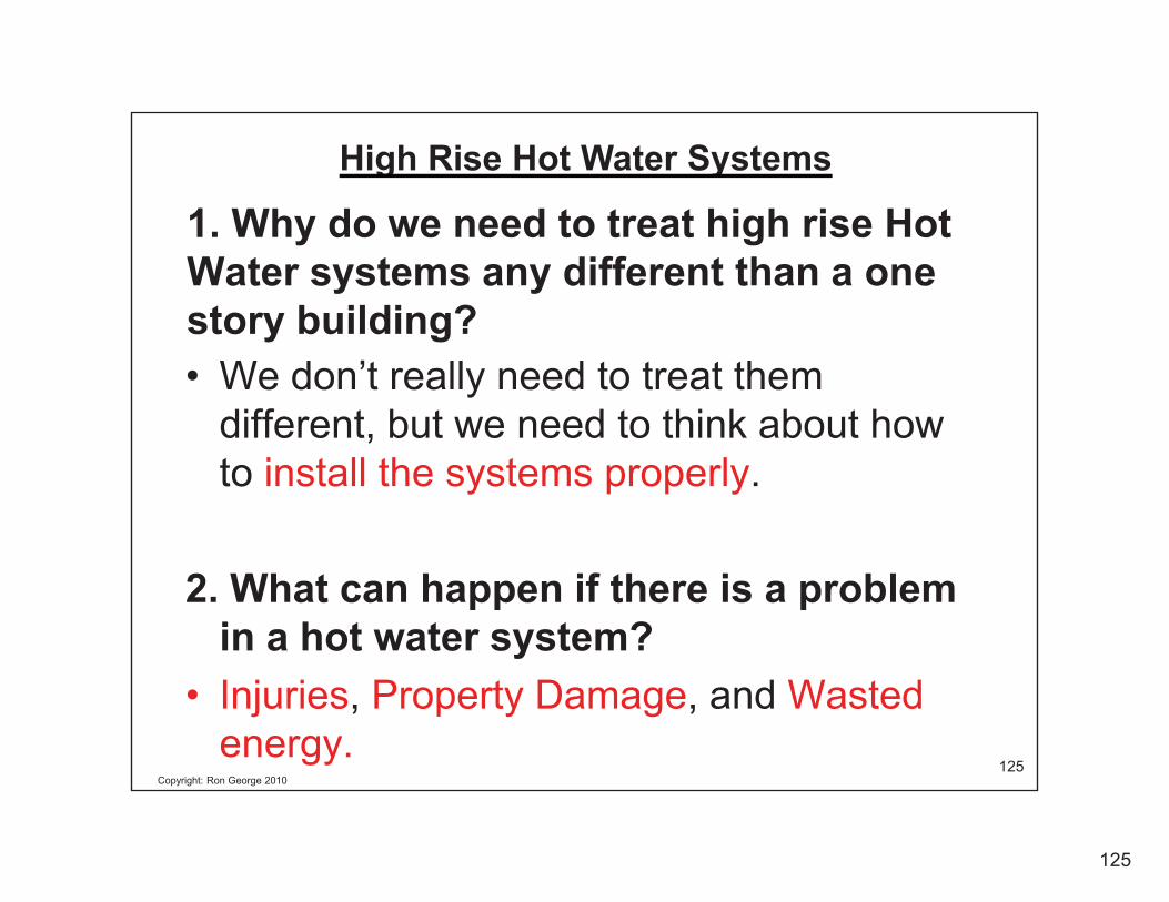
1. Why do we need to treat high rise Hot Water systems any different than a one story building?• We don’t really need to treat them
different, but we need to think about how to install the systems properly.
2. What can happen if there is a problem in a hot water system?
• Injuries, Property Damage, and Wasted energy.
High Rise Hot Water Systems

126
Copyright: Ron George 2010126
High Rise Bldg. Hot Water System DesignWhat are the unique challenges for high rise building plumbing systems?
1. Water Pressure2. Pressure Zones3. Venting (Gas Appliance Flue/Vent Routing)
4. Floor Space (Water Heaters)
5. Ceiling Space6. Pipe, Valve & Equip Pressure
ratings7. Balanced Press HW-CW
- Scalding/Thermal Shock- Crossover of HW to CW or CW to HW
8. Water Heater Type/Location9. Pipe Expansion & Contraction
Zone 4
Zone 3
Zone 2
Zone 1
Zone 6
Zone 5

127
Copyright: Ron George 2010127
High Rise Bldg. Hot Water System Design
10. Water Hardness11. Softening12. Corrosion13. Peak Demand Loads14. Hot Water Circulation
- Sizing HW Circ. Piping- System Piping configuration- Circ Pump Location- Air Vents
15. Excess Pressure relief16. Temperature control17. Combined Systems (HVAC-PLBG)
What are the unique challenges for high rise building plumbing systems?
Zone 4
Zone 3
Zone 2
Zone 1
Zone 6
Zone 5

128
Copyright: Ron George 2010128
There are many High Rise System HW Design Configurations.
1. Some are sustainable and many are not sustainable.
2. We covered Pressure Zones in the High Rise Building for CW Systems.
3. Many of the pressure zone issues apply here also.
4. The key is to keep the HW system within one pressure zone. You will see why.

129
Copyright: Ron George 2010129
Hot Water Pressure Zones Piping Configurations
HW
ISOL. VALVE
AIR VENTS THRU BRANCH TO TOP FIXTURE
HW
Fig. 1 - HW UPFEED SYSTEM(WH LOCATED OT THE BOTTOM)
HW
HW
R
HWR
CHECK VA.
BALANCING VALVE
HW
HW
HW
R
HW
HW
HW
HW
R
HWRH
WH
WHW
HW
RHWR
One
Pre
ssur
e Zo
ne 1
00 F
T M
ax.

130
Copyright: Ron George 2010130
Hot Water Pressure Zones Piping ConfigurationsAUTOMATIC AIR VENT
HW
Fig. 2 - HW DOWNFEED SYSTEM(WH LOCATED OT THE BOTTOM)
HW
HW
R
HW
HW
R
HW
HW
R
HW
HW
R
HW
HW HW
ISOL. VALVE
CHECK VA.
BALANCING VALVE
One
Pre
ssur
e Zo
ne 1
00 F
T M
ax.

131
Copyright: Ron George 2010131
Hot Water Pressure Zones Piping Configurations
Fig. 3 – UPFEED AND DOWNFEED SYSTEM(WH LOCATED OT THE BOTTOM)
HW
HWR
HW
HW
HW
R
HWHW
HW
HWR
HW
HW
HW
R
HW
AIR VENTS THRUBRANCH TO TOP FIXTURE
One
Pre
ssur
e Zo
ne 1
00 F
T M
ax.

132
Copyright: Ron George 2010132
Hot Water Pressure Zones Piping Configurations
Fig. 4 – UPFEED AND DOWNFEED SYSTEM(WH LOCATED OT THE BOTTOM)
ADD AIR VENT AT HIGH POINT IN PIPING BEFORE CIRC PUMP
HW
HWR
HW
HW
HWR
HW
HW
HW
HWR
HW
HW
HWR
HW
One
Pre
ssur
e Zo
ne 1
00 F
T M
ax.

133
Copyright: Ron George 2010133
HW
HW
HW
50
40
60
70
80
65
8080
8080808080808080 135
80
80
130125
115
145
11010510095908580
75706560
5550
4540
120
45
55
75
140
50
40
60
70
80
65
8080
8080808080808080
80
80
75
55
45
135130125
115
145
11010510095908580
706560
50
40
120
45
55
75
140
HW
RE-PRESSURIZATION PUMP 1/2 HP
RE-PRESSURIZATION PUMP 1/4 HP
RE-PRESSURIZATION PUMP 1/3 HP
RE-PRESSURIZATION PUMP 3/4 HP
RE-PRESSURIZATION PUMP 1 HP
RE-PRESSURIZATION PUMP 1/2 HP
RE-PRESSURIZATION PUMP 3/4 HP
RE-PRESSURIZATION PUMP 1 HP
RE-PRESSURIZATION PUMP 2 HP
RE-PRESSURIZATION PUMP 1 HP
RE-PRESSURIZATION PUMP 1-1/2 HP
RE-PRESSURIZATION PUMP 1-1/2 HP
Hot Water Pressure Zones - Piping Mistakes
Relief Valve opens at 150 PSI
DO NOT CIRCULATE HW THROUGH PRVs (100 Feet max. Pressure Zone Height.)
One
Pre
ssur
e Zo
ne =
100
FT
Max
.
No Circulation

134
Copyright: Ron George 2010134
Hot Water Pressure Zone Piping Mistakes
HW
HW
HW
50
40
60
70
80
65
8080
8080808080808080 135
80
80
130125
11511010510095908580
75706560
5550
4540
120
45
55
75
140
50
40
60
70
80
65
8080
8080808080808080
80
80
75
55
45
135130125
11511010510095908580
706560
50
40
120
45
55
75
140
HW
RE-PRESSURIZATION PUMP 1/2 HP
RE-PRESSURIZATION PUMP 1/4 HP
RE-PRESSURIZATION PUMP 1/3 HP
RE-PRESSURIZATION PUMP 3/4 HP
RE-PRESSURIZATION PUMP 1 HP
RE-PRESSURIZATION PUMP 1/2 HP
RE-PRESSURIZATION PUMP 3/4 HP
RE-PRESSURIZATION PUMP 1 HP
RE-PRESSURIZATION PUMP 2 HP
RE-PRESSURIZATION PUMP 1 HP
RE-PRESSURIZATION PUMP 1-1/2 HP
RE-PRESSURIZATION PUMP 1-1/2 HP
High Pressure = High Velocity = Damage to Press Reducing Valve Seats.
DO NOT CIRCULATE HW THROUGH PRVs (100 Feet max. Pressure Zone Height.)

135
Copyright: Ron George 2010135
HWR
HWHW
AIR VENT or HW BRANCH AHEAD OF CIRC PUMP
HWR
HWHW
AIR VENTS THRUBRANCH TO TOP FIXTURE
10 F
loor
s M
ax.
Central Water Heaters
(100
Fee
t)10
Flo
ors
Max
.
(100
Fee
t)
Correct Piping for Hot Water Pressure Zones
136
Copyright: Ron George 2010136
HW
CW
135130125
115
145
11010510095908580
706560
50
40
120
45
55
75
140
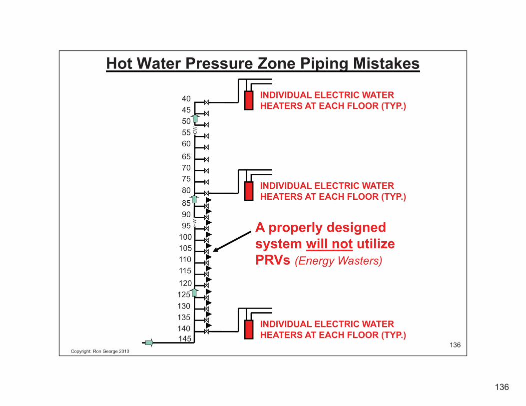
A properly designed system will not utilize PRVs (Energy Wasters)
INDIVIDUAL ELECTRIC WATER HEATERS AT EACH FLOOR (TYP.)
INDIVIDUAL ELECTRIC WATER HEATERS AT EACH FLOOR (TYP.)
INDIVIDUAL ELECTRIC WATER HEATERS AT EACH FLOOR (TYP.)
Hot Water Pressure Zone Piping Mistakes

137
Copyright: Ron George 2010137
Domestic Water Booster PumpGreen High Rise Plumbing Designs
(2) 100% pumps
PRVs = Energy Wasters
CheapDeveloperconstructionMethodswaste large amounts of energy
For a little more first cost, energy savings can paybackinitial costs in less than 1 to 3 years.
Uses 1/4 to 1/3of the energy of Design #1
Design #1 Design #2
Uses up to 4 Times the energy of Design #2
(3) pumps

138
Copyright: Ron George 2010138
MaximumRecommendedVelocity of HW in copper tubing is 5 FeetPer Second(Source:Copper Development Association)

139
Copyright: Ron George 2010139
Thermal Expansion Tanks
PRV
ThermalExpansionTank
PRV Water Heater
Water Heater
Installation of a thermal expansion tank will protect the water heater and all associated components in the HW System from excessive pressure.
Distorted Water Heater from Excess pressure over 100 PSI will crack a glass lining and void the Manufacturer’s warranty.

140
Copyright: Ron George 2010140
Thermal Expansion Tanks
Floor Mounted Expansion Tank
Pipe Mounted Expansion Tank

141
Copyright: Ron George 2010141
Thermal Expansion Tanks
Figure 1. As the water temperature increases, the expanded water is received by the tank.
Figure 2. As the water and pressure reaches its maximum, the diaphragm flexes against the air cushion (air is compressible) to allow for increased water expansion.
How they work.
142
Copyright: Ron George 2010142
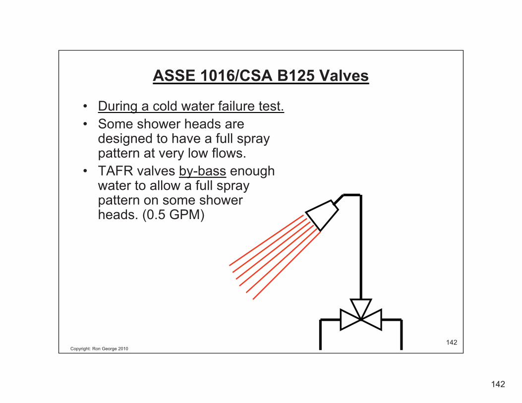
ASSE 1016/CSA B125 Valves
• During a cold water failure test.• Some shower heads are
designed to have a full spray pattern at very low flows.
• TAFR valves by-bass enough water to allow a full spray pattern on some shower heads. (0.5 GPM)

143
Copyright: Ron George 2010143
Water Droplet Size
• If water droplets are small enough, they can be inhaled increasing the risk of Legionnellae.

144
Copyright: Ron George 2010144
Plumbing Engineers recommend storage temperatures of 135 ºF - 140ºF and delivery temperatures of 120ºF maximum.
• 140ºF Water Storage Temperatures Kill Bacteria and Pathogens in the hot water such as Legionellae.
140 Deg F Storage Temp

145
Copyright: Ron George 2010145
The Effect of Temperature on Legionellae Bacteria
• Below 68�F legionellae can survive but are dormant• Legionellae growth range (68�F - 122�F)• Ideal growth range (95�F - 115�F)• Above 122�F legionellae can survive but do not
multiply• At 131�F legionellae die within 5 to 6 hours• At 140�F legionellae die within 32 minutes• At 150�F legionellae die within 2 minutes• Disinfection range (158�F - 176�F)

146
Copyright: Ron George 2010146
Ideal Legionella Bacteria Growth TemperatureRange

147
Copyright: Ron George 2010147
Gas Fired Storage Tank Design
Low storage Temps Make
a Bacteria Incubator

148
Copyright: Ron George 2010148
Horizontal Steam supplied Hot water Generator
Heated WaterSafetyReliefValve
Recirculated Water Make Up Water
Heat Exchanger
Liquid or GasFilled Bulb
CondensateReturn
V.B.
F&TTrap
TemperatureReg Valve
SteamSupply
P
Thermo-meter
Temperature signalis “fed back” throughcapillary tube
Recirculatin Pump
Storage TankScale build-up
Lowers Storage Temps and Makes a
Bacteria Incubator
149
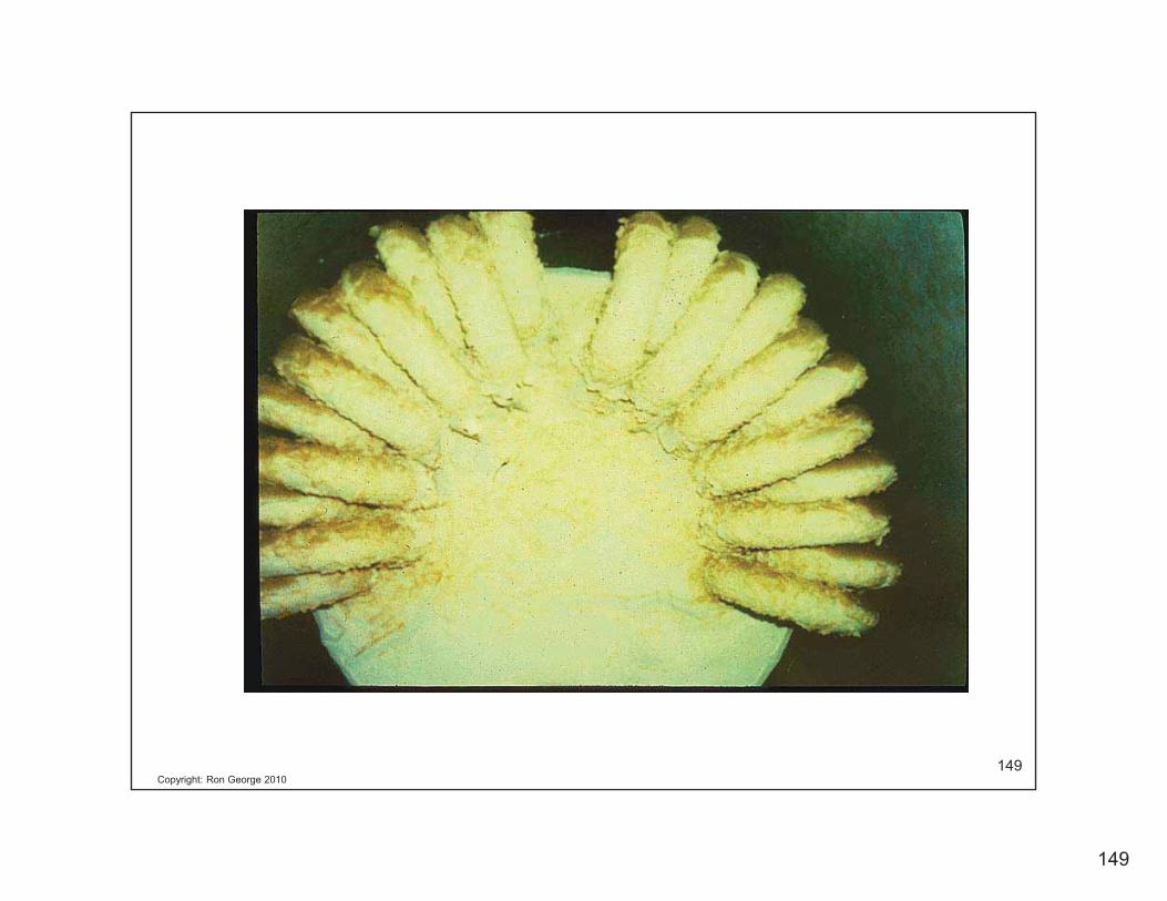
Copyright: Ron George 2010149
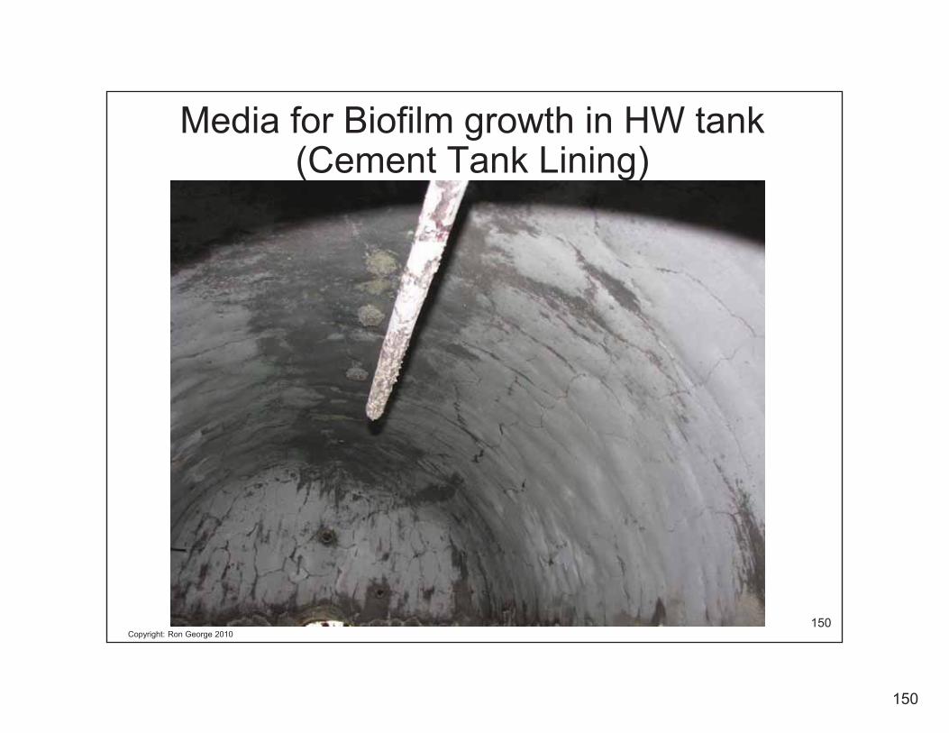
150
Copyright: Ron George 2010150
Media for Biofilm growth in HW tank (Cement Tank Lining)

151
Copyright: Ron George 2010151
Why use Thermostatic Mixing Valves?
• Safety: Accurately and Safely deliver water to points of use when the water storage temperatures have been increased to:
A) Eliminate legionella incubationB) Deliver water at a safe temperature for
bathing.C) Prevent flue gases from condensing in gas
fired water heaters

152
Copyright: Ron George 2010152
TemperatureReg Valve Relief
ValveTemperature Signal
is “fed back” throughcapillary tube
Thermometer
SteamSupply
I.B. Trap
F&T Trap
CondensateReturn
SupplyWater
HeatedWater
Shell & Tube Heat Exchanger
V.B.
Tankless Instantaneous Feedback System

153
Copyright: Ron George 2010153
Steam “Feed-Back” designs often have:
A lag time from message to action which can cause Significant temperature fluctuations.
A difficulty managing diverse (low) flows which can cause temperature inconsistencies.
Tankless Instantaneous Feedback System

154
Copyright: Ron George 2010154
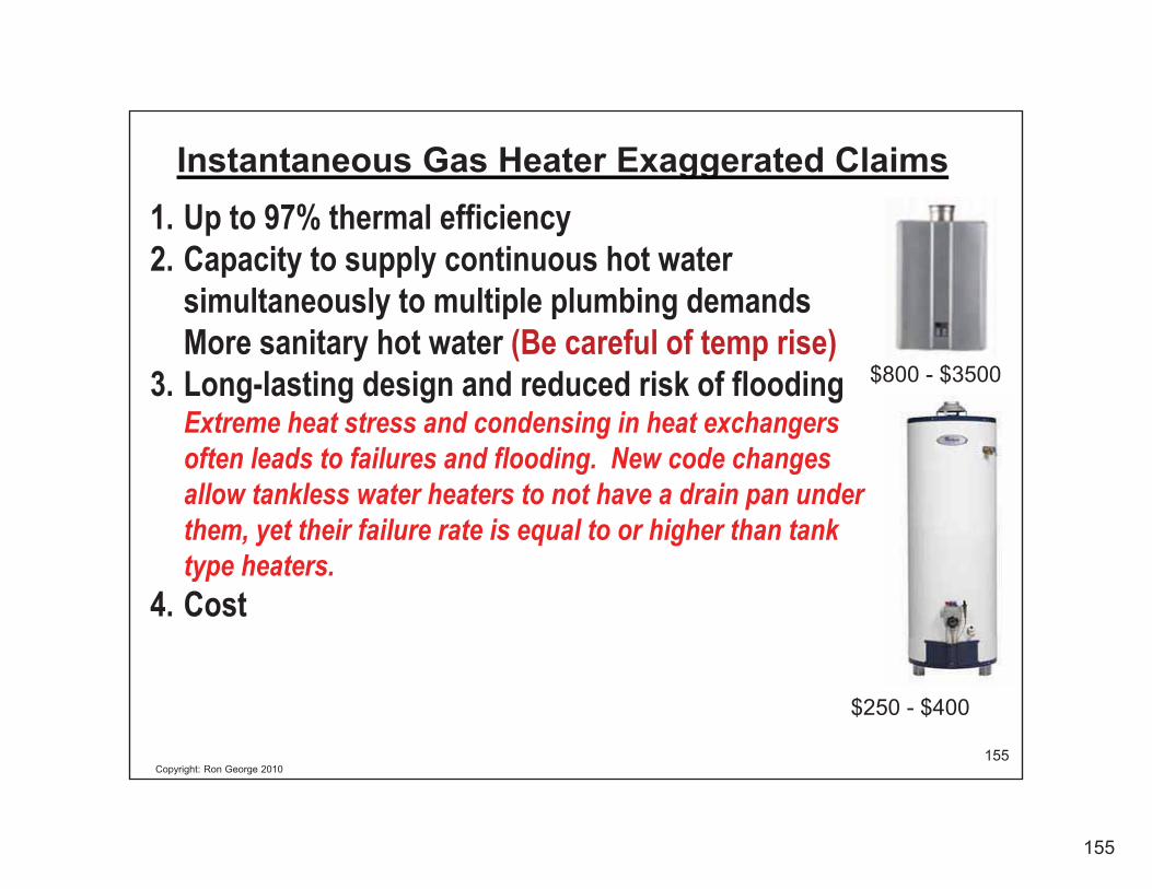
Instantaneous Water HeatersElectric, Gas or Steam Models Often have:1. Fluctuations in Temperature as usage varies.2. Newer instantaneous gas water heaters use a control valve to
modulate flow to help address temperature fluctuations. This causes fluctuations in system pressure.
3. They have difficulty managing diverse (low) flows which can cause temperature inconsistencies.
4. Many operate with a flow switch and do not activate at low flows.5. There are often exaggerated performance claims.6. They are suitable where there is a remote location and temperatures
are not critical.
155
Copyright: Ron George 2010155
Instantaneous Gas Heater Exaggerated Claims1. Up to 97% thermal efficiency2. Capacity to supply continuous hot water
simultaneously to multiple plumbing demandsMore sanitary hot water (Be careful of temp rise)
3. Long-lasting design and reduced risk of flooding Extreme heat stress and condensing in heat exchangers often leads to failures and flooding. New code changes allow tankless water heaters to not have a drain pan under them, yet their failure rate is equal to or higher than tank type heaters.
4. Cost
$250 - $400
$800 - $3500

156
Copyright: Ron George 2010156
Combining Heating Hot Water Systems andDomestic Hot Water Systems do NOT work.
157
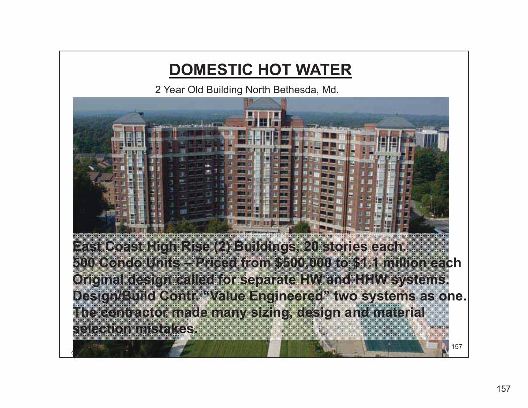
Copyright: Ron George 2010157
2 Year Old Building North Bethesda, Md.
DOMESTIC HOT WATER
East Coast High Rise (2) Buildings, 20 stories each.500 Condo Units – Priced from $500,000 to $1.1 million eachOriginal design called for separate HW and HHW systems.Design/Build Contr. “Value Engineered” two systems as one.The contractor made many sizing, design and material selection mistakes.

158
Copyright: Ron George 2010158
Over one Million Dollars for some of the 500 Condos in this Building.
DOMESTIC HOT WATER

159
Copyright: Ron George 2010159
Galvanized HW Piping

160
Copyright: Ron George 2010160
Galvanized HW Pipes!
161
Copyright: Ron George 2010161
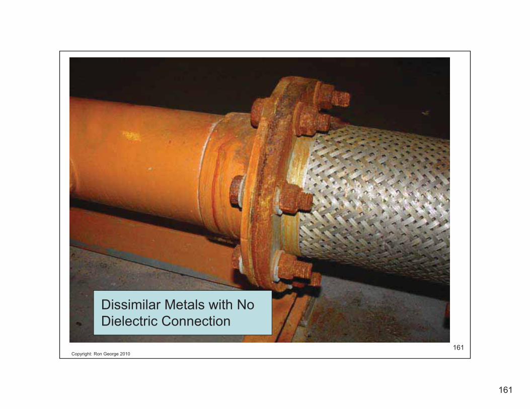
Dissimilar Metals with No Dielectric Connection

162
Copyright: Ron George 2010162
DOMESTIC HOT WATER

163
Copyright: Ron George 2010163
HW Recirc/Booser Pump Package # 2 of 3. Pumps & PRVs were replaced every 6 months
Not sustainable

164
Copyright: Ron George 2010164
Atmospheric -vs- Fan Assisted Combustion Technology
Atmospheric Fan assisted
Burner on: Heats well
Burner off: Draft Cools water
75% + - Efficient
Burner on: Heats well
Burner off: No draft heat loss
80-93% + - Efficient

165
Copyright: Ron George 2010165
• Scalding can occur when the temperatures exceed 120 degrees F.
• Thermal Shock can occur if the fixtures are too far from water heater with no temperature maintenance system. (Closer Apts/Recent use)
• Thermal Shock can occur if there is a sudden change in pressure between hot & cold water supplies to a fixture & there is no Safety Type Shower Valve installed.
• Only a Combination Press Balance/Thermostatic valveprotects against both temperature and pressure fluctuations.
• Thermal shock often leads to slip & fall injuries.
• HW Recirculation Pump failure
More Common HW System Problems
166
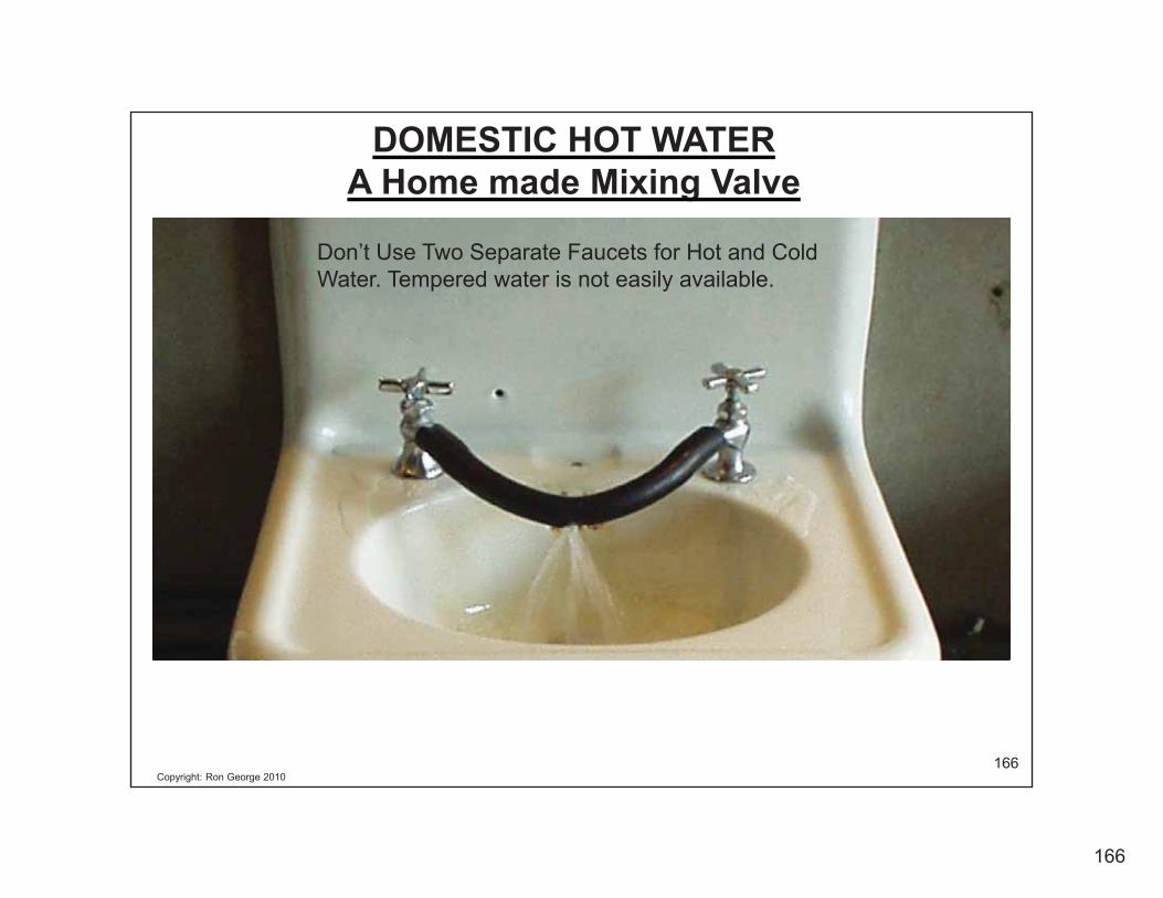
Copyright: Ron George 2010166
Don’t Use Two Separate Faucets for Hot and Cold Water. Tempered water is not easily available.
DOMESTIC HOT WATERA Home made Mixing Valve