occupancy sensor design and application guide · pdf fileoccupancy sensor design and...
TRANSCRIPT

Occupancy Sensor
Design and Application Guide
Energy saving report
SCENE
DIM
DIGITAL
O c c u p a n c y S e n s o r s
OSAPPS_1204

www.wattstopper.com8 0 0 . 8 7 9 . 8 5 8 5
SCENE
DIM
DIGITALO c c u p a n c y S e n s o r s
1
Occupancy sensor design guide introduction
Now that you’ve determined that occupancysensors are the right lighting control strategyfor your facility, choosing and implementingthe ideal sensor for each application isessential to achieving the most efficient andreliable control. This design and applicationguide aids the lighting professional in select-ing, laying out, specifying, installing andcommissioning an occupancy-based lightingcontrol system.
In this guide you’ll find:
• A flow chart that helps select the correct sensor technology for each application.
• A list of dos and don’ts that are important rules to follow for every installation.
• Detailed design steps for implementing occupancy-based control, where you’ll beguided through selecting and implementing the appropriate occupancy sensor productfor each application. Design steps include:
Step 1. Evaluate space characteristics
Step 2. Match sensor technology to an application
Step 3. Layout and specify
- Select coverage patterns
- Select product features
- Choose power pack
- Integrate with other control devices
Step 4. Installation and commission
- Select optimal mounting configuration
- Sensor placement, installation, and settings
• Application examples for specific building spaces
Together, these tools will help you in defining and implementing the optimal occupancy-based control solution for every type of building space.
Watt Stopper/Legrand’s application experts are available for design support and assis-tance on any lighting control question. Call our technical support at 800-879-8585.
Introduction

Is spaced usedintermittently? Are lights
left on in unoccupiedspaces?
Are there energy codecompliance requirements?
Are ceiling heights less than 14 feet?
Would you like occupancy-based controls?
Does space containpartitions, large
equipment or furniture?
Is there a small or morespecific area needed for
detection?
Yes
No
No
Does space containpartitions, large equipment
or furniture?
Is there a clear line of sight to all areas?
Ultrasonic
PIR
No
Yes
Other control strategiesare more appropriate.
No
Yes
Yes
Are there definite spaceboundaries?
Yes
Yes
No
Yes No
Is there a high volume of air flow?
Is there moving mechanicalequipment in the space?
DT or Ultrasonic
DT or Ultrasonic
Yes
NoYes
No
No
Can owner choose anappropriate mounting
location away from air flow?
YesNoYes
DT or Ultrasonic
No
Yes
No
No PIR
PIR
Is space small or welldefined?
PIRWould installation of
additional sensors justifypayback?
Yes
Yes
No
Other control strategiesare more appropriate.
Other control strategiesare more appropriate.
Occupancy sensor selection flow chart
Although there are several steps involved in implementing occupancy sensor controls(outlined on the following pages), this flow chart offers a quick way to determine whichsensor technology is best for your application.
www.wattstopper.com8 0 0 . 8 7 9 . 8 5 8 5 2
Energy saving report
SCENE
DIM
DIGITAL
O c c u p a n c y S e n s o r s

Following these rules helps to ensure that the sensors work effectively, providing comfortfor occupants while saving money for the facility. Be sure to review the following pages fordetailed product selection guidance.
Do• Use ultrasonic sensors in areas
screened by partitions or furni-ture
• Use PIR in enclosed spaces
• Create zones controlled by dif-ferent sensors to managelighting in large areas
• Use dual technology sensors forareas with very low activity levels
• Install sensors on vibration-free,stable surfaces
• Position sensors above or closeto the main areas of activity in aspace
• Mask the sensor lens to definecoverage of the controlled zoneeven more accurately
• Integrate sensor use with othercontrol methods (i.e. timescheduled control, daylighting)
• Educate occupants about thenew devices and what to expect
Don’t• Use ultrasonic sensors in spaces
with heavy air flow
• Install ultrasonic sensors inspaces where the ceiling heightexceeds 14 feet
• Use PIR sensors in spaceswhere there are fixtures or furni-ture that obstruct a clear line ofsight
• Install PIR sensors so that theirline of sight continues beyonddoorways
• Install sensors within 6-8 feet ofHVAC outlets or heating blowers
• Position a wall switch sensorbehind an office door
• Control emergency or exit light-ing with sensors
• Install PIR sensors in spaceswhere there are extremely lowlevels of occupant motion
Getting started “Dos and Don’ts”
www.wattstopper.com8 0 0 . 8 7 9 . 8 5 8 5 3
Energy saving report
SCENE
DIM
DIGITAL
O c c u p a n c y S e n s o r s

Identifying the ideal occupancy sensor for a particular application involves the considera-tion of several factors that are equally critical to an effective control solution. Becausedifferent sensors work best under different circumstances, incorporating these factorsinto the decision making process will provide optimal results:
Designing the occupancy sensor project
Design steps
Evaluate space characteristics
Match sensor technology toapplication
Understand coverage patterns
Select optimal mounting configuration
Evaluate space
characteristics
Match sensor
technology to
application
Understand
coverage patterns
Select optimal
mounting
configuration
Evaluate space characteristics
Match sensor technology toapplication
Understand coverage patterns
Select optimal mounting configuration
Evaluate space
characteristics
Match sensor
technology to
application
Understand
coverage patterns
Select optimal
mounting
configuration
1. Evaluate spacecharacteristics
2. Match sensortechnology to
application
3. Layout andspecify
4. Install andcommission
www.wattstopper.com8 0 0 . 8 7 9 . 8 5 8 5 4
Energy saving report
SCENE
DIM
DIGITAL
O c c u p a n c y S e n s o r s

To evaluate the application’s characteristics, designers should become familiar with:
• Room/space size and shape
• Location(s) of occupant activity and non-activity
• Location of walls, doors, windows and drapes
• Ceiling height
• Partition height and location
• Location of shelves, book cases, file cabinets, and large equipment
• Large objects that would block or alter a sensor’s coverage
• Location of HVAC ducts and fans
• Areas with available sunlight for added light level sensing
• Location of desk/workspace – orientation with regards to walls, partitions and otherobstacles
Special attention should be paid to high levels of vibration and/or air flow,extreme temperature conditions, and unusually low levels of activity becausethese issues may help identify the best technology solution.
Step 1 - Evaluate space characteristics
Spacecharacteristics
www.wattstopper.com8 0 0 . 8 7 9 . 8 5 8 5 5
Energy saving report
SCENE
DIM
DIGITAL
O c c u p a n c y S e n s o r s

Step 2 - Match technology to application
All Watt Stopper occupancy sensors use either passive infrared or ultrasonic technology,or a combination of both.
Passive infrared (PIR) technologyRelies on “line-of-sight” coverage to detect occupancy by sensing the difference in heatemitted by humans in motion from that of the background space.
Ultrasonic technologyUtilizes the Doppler principle to detect occupancy through emitting ultrasonic soundwaves throughout a space.
Dual technology (DT)Employs both PIR and ultrasonic technologies. DT sensors will activate lights when bothsensing technologies detect occupancy, but will continue to hold lighting on as long asonly one technology detects continued occupancy.
The matrix below summarizes these technologies and the space characteristics thatwould favor the use of one technology over another. Also use the flow chart on Page 3 tohelp determine which technology is ideal for your application
Note“Cut off” refers to the ability to clearly define or limit sensor coverage so that detectioncapability will not intrude into adjacent spaces.
Match sensortechnology to
application
Coverage type
Compatibleapplications
Incompatibleapplication
characteristics
PIR wall switches
- line of sight- cut off
- smaller, enclosedspaces
- low motion levelsby occupants
- obstacles blockingsensor view
Dualtechnology
sensors
- completecoverage
- cut off
- classroom- spaces with low
motion levels byoccupants
- high levels of airflow
- warehouse
Ultrasonicceiling sensors
- volumetric- no clear cut off
- open spaces- spaces with
obstacles- bathrooms
- high ceilings- high levels of
vibration or air flow
PIR ceiling &wall mount
sensors
- line of sight- cut off
- spaces where thesensor has a view ofthe activity
- low motion levels byoccupants
- obstacles blockingsensor view
www.wattstopper.com8 0 0 . 8 7 9 . 8 5 8 5 6
Energy saving report
SCENE
DIM
DIGITAL
O c c u p a n c y S e n s o r s

Step 3 - Specify and layout the project
Select coverage patternsMany different coverage sizes and shapes are available for each sensor technology. Whilea small application is easily covered with one sensor, larger applications benefit fromgrouping controlled lighting into zones (with each zone controlled by a sensor). Familiaritywith these coverage patterns will help designers specify the right product, ensuring thegreatest sensor accuracy and occupant comfort.
Do occupants engage in major motions, such as walking, or fine motions,such as typing or reading. Coverages change depending on motion type.
When creating zones of coverage, such as the coverage illustrated in theexample above, take care to ensure that sensor coverages overlap by 20%.
Coveragepatterns
Example (Dual technology coverage)
In a large space, such as a lecture hall,dual technology sensors provide coveragethat suits the variable levels of motion pre-sent. The DT-200 is mounted in the corner.Its passive infrared portion of coveragedefines exact cutoff near the doorway. TheDT-300, with 360° coverage, fills in the restof the space.
Products Used
DT-200 and DT-300 dual technology sensors
Example (Ultrasonic coverage)
In an open, partitioned office, designers select ultra-sonic sensors. To adequately cover the entire space,multiple sensors are positioned to cover a specific zone.
Products Used
Ultrasonic occupancy sensors (UT-300)
WT-2200
www.wattstopper.com8 0 0 . 8 7 9 . 8 5 8 5 7
Energy saving report
SCENE
DIM
DIGITAL
O c c u p a n c y S e n s o r s
50 ft.
40 ft.
Sensor
Sensor
50 ft.
40 ft.
Sensor Sensor
Manual-ON Switch

Step 3 - Specify and layout the project
Lighting designers should also consider specific features, which can add functionalityand flexibility to the control solution.
AlertsVisual (light flash) and/or audible alerts warn occupants of impending shutoff.
Dual relaysDual relay wall switches contain two separate relays for controlling two independentlighting loads or circuits. This satisfies bi-level lighting control energy code require-ments.
Hard lensWall switches that are placed in public spaces or schools require a lens that can stand upto substantial contact. Up to five times the thickness of a comparable wall switch lens, ahard lens makes the device resistant to vandalism or unintentional damage. The WN andWA wall switches offer a hard lens.
Isolated relayAn isolated relay enables interfacing with a facility’s HVAC, BAS, or monitoring systems.For example, people entering a building after hours trigger not only the necessarylighting, but the heat or A/C as well. In automatic wall switches, an isolated relay canbe used to control different circuits or loads.
Light levelThe light level feature holds lighting OFF when natural light levels rise above a pre-setlevel. This setting is adjustable and can be overridden. It is available in several WattStopper wall switches and ceiling sensors.
This light level feature is recommended for spaces that have access to abun-dant natural light. Although multiple sensors may be used, only one sensorshould be actively utilizing the light level feature within a controlled area.
Low profileMany applications call for lighting controls that don’t take up a lot of space and that leavethe ceiling looking uncluttered. Several Watt Stopper sensors are designed to beextremely low profile and compact.
NightlightWall switch sensors with built-in nightlights provide users with a bright LED thatremains illuminated whenever overhead lights are off.
ON Mode operationSome automatic wall switches feature a choice of either automatic or manual onoperation. For manual on operation with ceiling mount sensors, some sensors featurethe ability to work with a momentary low voltage switch for manual on/off operation.
Productfeatures
www.wattstopper.com8 0 0 . 8 7 9 . 8 5 8 5 8
Energy saving report
SCENE
DIM
DIGITAL
O c c u p a n c y S e n s o r s

SmartSet™SmartSet automatically adjusts the sensor’s time delay and sensitivity settings for opti-mal performance and energy efficiency. SmartSet is found in the WA, DT-300, UT-300, andCI-300 series sensors.
Terminal wiringContractor friendly terminal style wiring makes installation quick and easy by eliminatingthe need for wire nuts.
Voltage choice - line or lowHaving a choice of line or low voltage sensors, gives the installer the flexibility to use thetype of wiring that is most appropriate for their requirements.
Walk through ModeFor extra energy savings, walk through mode switches lights off three minutes after anarea is initially occupied if no motion is detected after the first 30 seconds.
Zero crossingZero Crossing Circuitry ensures that a wall switch sensor or power pack’s switching takesplace at the beginning of the voltage wave very close to zero volts. This reduces stress onthe relay and increases sensor life.
Step 3 - Specify and layout the project
Productfeatures
www.wattstopper.com8 0 0 . 8 7 9 . 8 5 8 5 9
Energy saving report
SCENE
DIM
DIGITAL
O c c u p a n c y S e n s o r s

WS-200
WA-200
WA-300
WI-200
WI-300
WN-100
WD series
CN-100
CW-100
CX series
CI-200 series
CI-300 series
UT-300 series
W series
WT series
DT-200 series
DT-300 series
Ale
rts
Dua
l rel
ays
Har
d le
ns
Isol
ated
rel
ay
Ligh
t lev
el
Low
pro
file
Nig
htlig
ht
ON
Mod
e op
erat
ion
Smar
tSet
™
Term
inal
wir
ing
Volt
age
choi
ce -
line
or
low
Wal
k th
roug
h M
ode
Zero
cro
ssin
g
*
* *
*
*
*
*
*
*
*
*
*
*
*
*
*
*
*
*
*
*
*
*
*
*
*
*
*
*
*
*
*
*
*
*
*
*
*
*
*
*
*
*
*
*
*
*
*
*
*
*
*
*
*
*
*
*
*
*
*
*
*
*
*
*
*
*
*
*
*
*
*
*
*
*
*
*
*
www.wattstopper.com8 0 0 . 8 7 9 . 8 5 8 5 10
Energy saving report
SCENE
DIM
DIGITAL
O c c u p a n c y S e n s o r s
Step 3 - Specify and layout the project
Productfeatures
matrix

Power packs are a key component of low voltage sensor based lighting control systems.Power packs provide low voltage power to sensors and other control devices and respondto signals from those devices to switch a relay(s). However, power packs can also provideadvanced features such as switched inputs, inputs for scheduling, and dimming control.These features and many others provide a finer degree of control over the different loadsin a building.
Single relay power packsProvide power to control devices and switch a single load in responseto a signal from the control devices. These power packs may alsoprovide additional control inputs to hold on or off the relay.
Auxillary packsUsed in conjunction with a power pack to switch other loads. Do not have a transformerso they do not provide power to a control device.
Form C power packsProvide customizable control scenarios by including two switching options in one relay.
Dual relay power packsCan switch two loads simultaneously from a single control device signal.
Intelligent power packsOffer advanced features to customize applications, including dual switch inputs,dimming capability, multiple control inputs, programmable switching scenarios.
Power suppliesProvide extra low voltage power for large applications with many control devices.
Step 3 - Specify and layout the project
Choose thepower pack
www.wattstopper.com8 0 0 . 8 7 9 . 8 5 8 5 11
Energy saving report
SCENE
DIM
DIGITAL
O c c u p a n c y S e n s o r s

Power output needsMatching the current consumption of all the devices connected to the power pack to theamount of power the power pack can provide is very important. Simply sum the currentconsumption ratings from all the sensors to be connected to one power pack. If this num-ber is less than the power pack output rating, the power pack is appropriate for theapplication. If the number is greater, consider decreasing the switching zones or provid-ing an extra power pack/supply to properly power the sensors
VoltageWhen selecting a power pack, consider the voltage of the electrical systems. Many powerpacks are capable of accepting a range of line voltage inputs, including two phase, whilesome are voltage specific. Pay attention to the input ratings of the power pack.
Relay typeThe relay in the power pack is the key component that switches the load. Many powerpacks provide an isolated relay so the power pack can switch a load that is different thanthe line voltage supplying the power pack. Isolated relays provide better switching flexibil-ity in different applications. Some power packs also have different types of relays so thespecifier can customize the switching of the application. While most power packs providea simple form A relay (normally closed) other power packs offer increased switching flexi-bility with a form C relay (both normally open and normally closed). In addition, largerpower packs may have two or more isolated relays in the same enclosure. These powerpacks can provide simultaneous or independent control of two or more loads. Smaller,low voltage rated relays may also be present in some power packs. These relays are usedto signal other systems such as security or HVAC systems.
Relay ratingsMost power packs can switch a full 20 Amp load which is sufficient for sensor basedlighting control. An exception to this load rating is the form C power packs. Make sure theload being switched does not exceed the load rating of the power pack.
Type of load to be switchedPower packs have specific ratings for different load types. Most common load types canbe controlled by power packs including incandescent, fluorescent and motor loads. Makesure the power pack relay ratings match the type of load to be controlled. One load type ofconcern for power packs are the newer electronic ballasts. These ballasts can causestrain on relays due to high inrush current. To alleviate this situation, many power packsuse zero crossing technology to eliminate the potential for relay damage from highinrush. If electronic ballasts are specified, try to choose a power pack that uses zerocrossing (such as the BZ-100 or the LC-100).
Step 3 - Specify and layout the project
Considerationswhen selecting a
power pack
www.wattstopper.com8 0 0 . 8 7 9 . 8 5 8 5 12
Energy saving report
SCENE
DIM
DIGITAL
O c c u p a n c y S e n s o r s

Power packs are generally mounted by a nippleexternally onto the knock-out of a junction box. Thisplaces the power pack itself in the plenum space.Make sure the power pack is plenum rated. Smallerpower packs can also be installed inside a standardjunction box. Power packs are designed so that linevoltage connections are made inside the junction boxand low voltage connections are made externally.Make sure all low voltage wiring is plenum rated as well.
Intelligent power packs provide inputs so that multiple control devices canbe connected. This allows the installer to customize the control scenariofor different applications and end user preferences. Use intelligent power packs whenmulti-device, manual switching, and dimming applications are considered.
Step 3 - Specify and layout the project
Mountingoptions
Signaling frommultipledevices
www.wattstopper.com8 0 0 . 8 7 9 . 8 5 8 5 13
Energy saving report
SCENE
DIM
DIGITAL
O c c u p a n c y S e n s o r s
Junction box
BLK PowerWHT Neutral
GRN Ground RED Output 1 RED Load & Line YLW Output 2 YLW Load & Line
LC-100Intelligent Power Pack
Model #:
800.879.8585 • 972.578.1699
0-10V Ballast
Daylight
Shed
Unoccupied
24VDC
Shed Signal
Time Clock
Photocell
OccupancySensor 24VDC
Designed and Manufactured in USA
Industrial Control
Equipment 83AJ
0162
7r1
1 B
link
Dis
able
2 O
N O
nly
whe
n oc
cupi
ed3
Aut
omat
ic O
N4
Dim
min
g5
Day
light
ing
Ena
ble
6 Ti
me
Ove
rrid
e #1
7 Ti
me
Ove
rrid
e #2
8 10
0 H
our B
urn
In
Configuration Switches
Load Output Rating 120/277VAC, 60Hz, 1hp 20Amp Tungsten or BallastAuxiliary Output Rating 1Amp, 24VDC
24VDC
OFF
ON
Sensor
24VDC
Com
Gray
Violet
- +ShedLevel
- +MaxLevel
Type 1 enclosureFor operation within a Maximum Ambient of 60°CAcceptable for use in plenum
Low voltage wiring

For increased flexibility and energy savings, occupancy sensors seamlessly integrate withmany lighting controls.
Lighting control panelsIntegrating occupancy sensors with lighting control panels provides convenience and sav-ings benefits. Rather than the panel’s system clock signalling all lights to turn off at aspecific time, occupancy sensor control takes over during after hours. Here, lights remainon only in spaces that are occupied, and turn off after the space is vacated.
Daylighting controlsOccupancy sensors also integrate well with daylighting controls in building spaces thatreceive daylight. When used together, the occupancy sensors can keep lights off in unoc-cupied spaces, even when the daylighting controls signal that there is not adequatedaylight.
Step 3 - Specify and layout the project
Integratingwith other
controldevices
www.wattstopper.com8 0 0 . 8 7 9 . 8 5 8 5 14
Energy saving report
SCENE
DIM
DIGITAL
O c c u p a n c y S e n s o r s

Step 4 - Install and commission
Watt Stopper sensors are available in three basicmounting configurations:
• wall switch replacements (line voltage)
• ceiling or wall mount sensors with power packs(low voltage)
• ceiling or wall mount (line voltage)
Wall switch replacementsWall switch sensors are designed to replace existing wallswitches. Wall switch sensors utilize passive infrared tech-nology and therefore require a clear line of sight of thecoverage area from the switch location.
Ceiling/wall mount sensorsSome sensors are recommended for ceiling mount use,such as the CI-200, W series, WT series, DT-300 series andWPIR. Others, such as the CX and DT-200 series, containbuilt-in bracket systems that provide ceiling mounting aswell as wall mounting. This is important for applications wherethe ceiling is unavailable for sensorinstallation.
Many ceiling/wall mount sensors areavailable in both line and low voltagemodels. Although both models providethe same function, there are situationswhen one model is a better choicethan the other.
Low voltageLow voltage occupancy sensors use a power pack. They offerflexible wiring configurations (such as multiple sensors wiredto a single power pack) and the placement of sensors on theceiling or wall is easy to change upon installation and duringbuilding renovations. However, in hard cap ceiling applications,a line voltage sensor is recommended.
Line voltageLine voltage occupancy sensors feature standard wiring (con-duit and wire), and terminal wiring makes installation easy.They are a good choice for applications where there is noplenum or junction boxes are hard to access.
WA-200.exploded
12
34
56
78
WA sensor replaces conventional wall switches
Rearhousing
Depluggable terminal
Frontcover
Ceiling
Spring clips (2)
DT-300 ceiling mount sensorThe DT-200 sensor can beinstalled on the ceiling (outlinedhere in black) or on the wall(outlined here as dotted line)
Power packs are used when lowvoltage ceiling sensors are selected.
Mountingconfiguration
4" Square, 2.25" Deep*Junction Box with Double Gang Mudring
Sensor
Screws
Ceiling
FrontCover
CI-355 line voltage ceiling mountsensor
www.wattstopper.com8 0 0 . 8 7 9 . 8 5 8 5 15
Energy saving report
SCENE
DIM
DIGITAL
O c c u p a n c y S e n s o r s

Step 4 - Install and commission
Sensor placementInstallers should position the sensor so ithas the best view of the entire coveragearea. Care should be taken to minimizethe possibility of false ONs or OFFs due tosensor location. For instance, an ultra-sonic sensor should not be positionednear an open doorway, since a passerbycould trigger lighting ON.
When installing ultrasonic sen-sors, installers should positionthe receiving side toward the areaof greatest traffic.
InstallationWhen installing the sensor, the contractor should wire it according to manufacturer’sinstructions to eliminate any functional problems or sensor damage. For instance, allWatt Stopper wall switch sensors require grounding for proper functioning.
SettingsFollowing sensor installation, additional adjustments may need to be made. This is oftendue to last minute changes in furniture or fixture placement. Ideally, the sensor settingsfor sensitivity and time delays should match the activity levels of the monitored spaces.For sensors that feature SmartSet technology, adjustments are typically not needed afterinstallation.
Placement
Installation
Settings
WS, WA or WI Automatic Wall Switch
12'
18'
This PIR wall switch has been positioned to look intothe room rather than out the door, minimizing thepossibility of false triggers. Nothing is obstructing thesensor’s view and it faces the front of the worker.
www.wattstopper.com8 0 0 . 8 7 9 . 8 5 8 5 16
Energy saving report
SCENE
DIM
DIGITAL
O c c u p a n c y S e n s o r s

Energy saving report
SCENE
DIM
DIGITAL
O c c u p a n c y S e n s o r s
Application Examples
www.wattstopper.com8 0 0 . 8 7 9 . 8 5 8 5

Application descriptionLarge office area with partitioned cubicles. Amajority of work is done at computers inindividual cubicles.
Control needsA sensor that can ‘see around’ obstacles suchas cubicle walls, and that has a high sensitiv-ity to detect fine movements such as typing.
SolutionUT-300 Ultrasonic Ceiling Sensors.
Ultrasonics detect movement through obstacles so occupants working in cubicles aredetected. To ensure the entire area receives coverage, place the sensors in zones thatoverlap.
Application descriptionEnclosed single-occupant office with a win-dow. Primary activities are computer work,reading and meetings.
Control needsON/OFF control with light level sensing. Thesensor should be able to detect small move-ments such as typing.
SolutionWA-200 Automatic Wall Switch Sensor.
The sensor replaces a standard wall switch. It should have a direct and clear view of thefront of the occupant. Be sure not to place the sensor behind a door or other obstacle thatblocks its view. Light level sensing ensures that lights stay off if enough ambient light isavailable in the room. The WA’s SmartSet technology automatically adjusts the time delayand sensitivity settings for optimal performance and savings.
Occupancy sensor applications
Partitioned officespace
Enclosed office
WS, WA or WI Automatic Wall Switch
12'
18'
42'
42'
www.wattstopper.com8 0 0 . 8 7 9 . 8 5 8 5 18
Energy saving report
SCENE
DIM
DIGITAL
O c c u p a n c y S e n s o r s

Application descriptionMedium conference room that is used for meetingsand training.
Control needsA sensor with ON/OFF control. The sensor shouldhave high sensitivity, as there is often little motionin the room during meetings. Lights need to becapable of staying off during presentations.
SolutionDT-300 360° Dual Technology Occupancy Sensor. The DT-300 uses both PIR and ultrasonictechnologies to sense occupancy, resulting in enhanced sensing capability for applicationswhere activity varies greatly. The sensor should be placed in the middle of the room. Amanual OFF override is useful when lights need to be off during presentations.
Application descriptionHigh school classroom.
Control needsON/OFF control with high sensitivity, since occupantssit still for long periods of time.
SolutionDT-200 Dual Technology Occupancy Sensor. The sen-sor accommodates lower levels of activity without falsetriggers. The DT-200 is corner mounted behind the teacher’s desk for optimum coverage,without seeing out the door.
Application descriptionElementary classroom.
Control needsAutomatic ON/OFF of lights based on occupancy.Daylight dimming of fixture row next to the windows.Manual ON/OFF and dimming of two zones of lightsfor different presentation scenes: one zone is themiddle lamps of direct/indirect fixtures, the secondzone is the outer lamps.
SolutionLC-100 Intelligent Power Pack, DT-200 Dual Technology Occupancy Sensor and LS-301Dimming Photosensor. The occupancy and photosensors can be connected to a singleLC-100. In addition, the LC-100 facilitates dual zone switching and dimming with its dualrelay and dual 0-10V dimming outputs. A low voltage momentary switch is simply con-nected to the dual switch inputs.
Occupancy sensor applications
Conference/training room
Classroom
Classroom
DT-200
30'
30'
D
D
win
dow
DT-300
28'
30'
www.wattstopper.com8 0 0 . 8 7 9 . 8 5 8 5 19
Energy saving report
SCENE
DIM
DIGITAL
O c c u p a n c y S e n s o r s
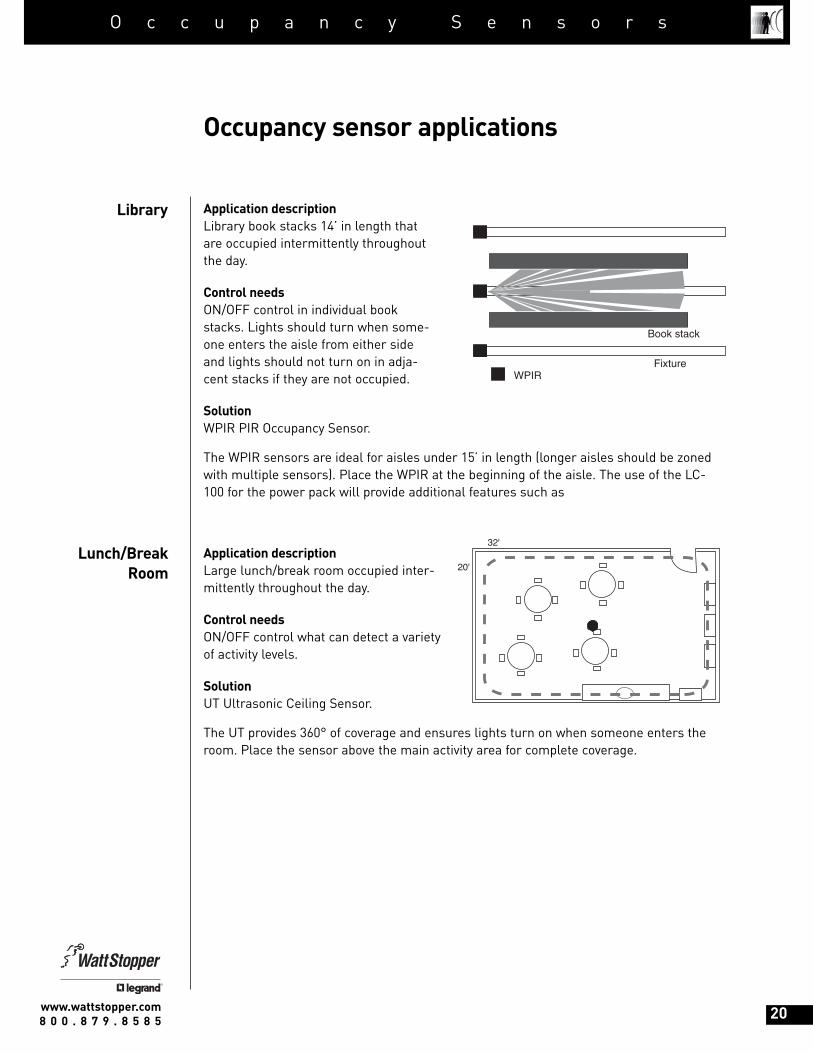
Application descriptionLibrary book stacks 14’ in length thatare occupied intermittently throughoutthe day.
Control needsON/OFF control in individual bookstacks. Lights should turn when some-one enters the aisle from either sideand lights should not turn on in adja-cent stacks if they are not occupied.
SolutionWPIR PIR Occupancy Sensor.
The WPIR sensors are ideal for aisles under 15’ in length (longer aisles should be zonedwith multiple sensors). Place the WPIR at the beginning of the aisle. The use of the LC-100 for the power pack will provide additional features such as
Application descriptionLarge lunch/break room occupied inter-mittently throughout the day.
Control needsON/OFF control what can detect a varietyof activity levels.
SolutionUT Ultrasonic Ceiling Sensor.
The UT provides 360° of coverage and ensures lights turn on when someone enters theroom. Place the sensor above the main activity area for complete coverage.
Occupancy sensor applications
Library
Lunch/BreakRoom
WT-1100 or W-1000A
20'
32'
WPIR
Book stack
Fixture
www.wattstopper.com8 0 0 . 8 7 9 . 8 5 8 5 20
Energy saving report
SCENE
DIM
DIGITAL
O c c u p a n c y S e n s o r s

Application descriptionSmall utility room used sporadically during theday.
Control needsON/OFF sensor that ensures lights come on assoon as the door opens.
SolutionWS-200 PIR Wall Switch Sensor.
The sensor directly replaces the wall switch. Itshould not have obstacles that block coverage,as PIR technology cannot see around objects.
Note: as an alternative to using occupancy sensors, the TS Digital Time Switch is wellsuited to areas such as utility rooms where the lights remain on for a preset, useradjustable amount of time.
Application descriptionAisleways in a warehouse with high ceil-ings. Aisles are occupied sporadicallythroughout the day.
Control needsON/OFF control that only triggers lights inthe aisleway that is occupied.
SolutionCX-100 PIR Ceiling Sensor.
The CX can be mounted at ceiling heightsup to 50 feet. The sensor’s coverage zonecan be tightly defined so lights are on only where needed.
Occupancy sensor applications
Utility Room
Warehouse
CX-100-3
WS-200
15'
17'
www.wattstopper.com8 0 0 . 8 7 9 . 8 5 8 5 21
Energy saving report
SCENE
DIM
DIGITAL
O c c u p a n c y S e n s o r s

Application descriptionPublic restroom with six parti-tioned stalls. Ceiling is hard-capor concrete.
Control needsON/OFF control with technologythat can see around obstacles.
SolutionThe UT-355 line voltageUltrasonic Sensor.
Place the sensor close to the stalls, about 2’ out from the stall door so the sensor has thebest opportunity to detect presence in the entire restroom. Special attention should begiven to larger stalls to ensure they are well covered. Use the UT-355 in restrooms withhard-cap or concrete ceilings. Add a 4 square or Wiremold junction box to mount the sen-sor on to the ceiling surface.
Application descriptionLobby with high ceilings and windows.
Control needsON/OFF control and light level sensing. The sen-sor should also provide accurate coverage atgreater heights and a defined cut off.
SolutionDT-200 Dual Technology Occupancy Sensor.
Place the sensor behind the reception desk so itcan see the entire space while also detecting small movements at the desk. Pay specialattention to covering the entrance, reception desk and waiting area. In addition, the DT-200 features light level sensing, which increases energy savings by keeping lights offwhen ambient light is sufficient.
Additionally, the lobby would be an ideal application for integrating daylighting controls.
Occupancy sensor applications
Restroom
Lobby
DT-200 or CX-100 STAIRSHALLWAY
RECEPTION
Exit
24'
30'
WT-1100 or W-1000A Standard toggle switch
28'
20'
www.wattstopper.com8 0 0 . 8 7 9 . 8 5 8 5 22
Energy saving report
SCENE
DIM
DIGITAL
O c c u p a n c y S e n s o r s

Occupancy sensor applications
Hallway
Hotelguestrooms
Application descriptionOffice building hallway withwalls on both sides. The hall-way has no windows, but hasdoors along each side.
Control needsON/OFF control that ensures lights turn on immediately when someone enters thehallway from either side or from a doorway.
SolutionWT-2250 Ultrasonic Sensor.
Place the sensor in the middle of the hallway, halfway between entrances. The sensorwill detect when someone enters the hallway from either side or when someoneenters though a door in the middle of the hallway.
Application descriptionHotel guestroom bathroom
Control needsLights turn off automatically based on occu-pancy. Since guests don’t always want lightson in the bathroom, lights should not turn onautomatically when the room is occupied.Provide users with a nightlight that is illumi-nated when the overhead lights are off.
SolutionWN-100 Motion Sensor Nightlight Switch.
The WN directly replaces a bathroom wall switch. As a convenience to guests, the WNprovides a nightlight when lights are off. A button on the front of the switch allowsguests to turn on lighting when desired. Lights automatically turn off during times ofvacancy.
WT-2250
WN
25'
10'
www.wattstopper.com8 0 0 . 8 7 9 . 8 5 8 5 23
Energy saving report
SCENE
DIM
DIGITAL
O c c u p a n c y S e n s o r s