nvx80 - sisteme alarma incendiu ssc · nvx80 high end motion detector with anti-mask for...
TRANSCRIPT

NVX80 High End Motion Detector with Anti-Mask for Indoor/Outdoor Use V1.02
Reference and Installation Manual
PARADOX.COMPrinted in Canada - 03/2013
NVX80-EI00
Introduction ................................................................................................................................................3
Installation ..................................................................................................................................................6
Menus .........................................................................................................................................................9
Outputs and Wall Tamper In (Input) ..........................................................................................................11
Power Up ..................................................................................................................................................11
Settings ....................................................................................................................................................12
Diagnostics ...............................................................................................................................................12
Anti-Masking ............................................................................................................................................13
Display Icons ............................................................................................................................................14
Passive Infrared Detection with Independent Creep Zone.......................................................................16
Microwave ................................................................................................................................................17
Alarm Condition ........................................................................................................................................17
Pet Immunity ............................................................................................................................................17
Tamper ......................................................................................................................................................18
Notifications .............................................................................................................................................19
About Us ..................................................................................................................................................20
Firmware Upgrades ..................................................................................................................................20
2 NVX80 Version 1.02
Table of Contents
WarrantyFor complete warranty information, please visit www.paradox.com/terms. Your use of the Paradox product signifies your acceptance of all warranty terms and conditions. ENVY Series is a trademark or registered trademark of Paradox Ltd. or its affiliates in Canada, the United States and/or other countries. For the latest product approvals, such as UL and CE, please visit www.paradox.com. © 2013 Paradox Security Systems Ltd. or Paradox Security Systems (Bahamas) Ltd.. All rights reserved. Specifications may change without prior notice.
PatentsOne or more of the following US patents may apply: 7046142, 6215399, 6111256, 6104319, 5920259, 5886632, 5721542, 5287111, and RE39406 and other pending patents may apply. Canadian and international patents may also apply.
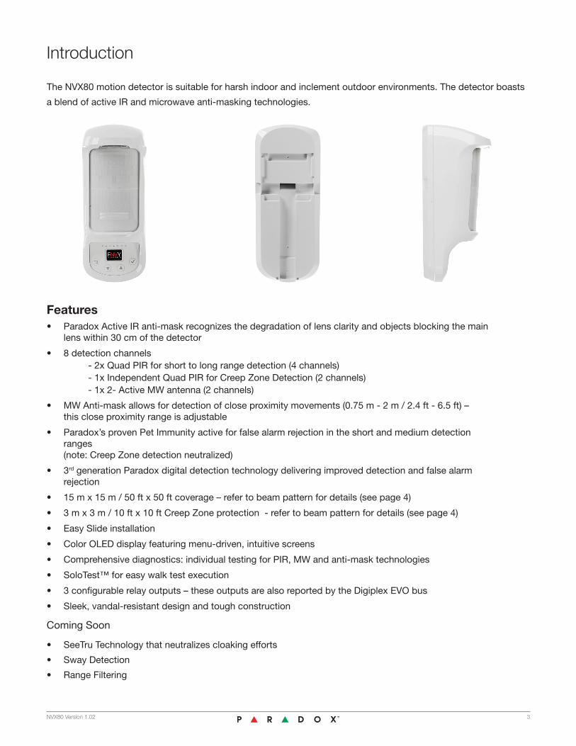
The NVX80 motion detector is suitable for harsh indoor and inclement outdoor environments. The detector boasts
a blend of active IR and microwave anti-masking technologies.
NVX80 Version 1.02 3
Introduction
Features• Paradox Active IR anti-mask recognizes the degradation of lens clarity and objects blocking the main
lens within 30 cm of the detector
• 8 detection channels - 2x Quad PIR for short to long range detection (4 channels) - 1x Independent Quad PIR for Creep Zone Detection (2 channels) - 1x 2- Active MW antenna (2 channels)
• MW Anti-mask allows for detection of close proximity movements (0.75 m - 2 m / 2.4 ft - 6.5 ft) – this close proximity range is adjustable
• Paradox’s proven Pet Immunity active for false alarm rejection in the short and medium detection ranges (note: Creep Zone detection neutralized)
• 3rd generation Paradox digital detection technology delivering improved detection and false alarm rejection
• 15 m x 15 m / 50 ft x 50 ft coverage – refer to beam pattern for details (see page 4)
• 3 m x 3 m / 10 ft x 10 ft Creep Zone protection - refer to beam pattern for details (see page 4)
• Easy Slide installation
• Color OLED display featuring menu-driven, intuitive screens
• Comprehensive diagnostics: individual testing for PIR, MW and anti-mask technologies
• SoloTest™ for easy walk test execution
• 3 configurable relay outputs – these outputs are also reported by the Digiplex EVO bus
• Sleek, vandal-resistant design and tough construction
Coming Soon
• SeeTru Technology that neutralizes cloaking efforts
• Sway Detection
• Range Filtering

4 NVX80 Version 1.02
Beam Patterns

NVX80 Version 1.02 5
Coverage Pattern 90º
Installation Height Minimum 2.5 m / 8 ft - Maximum 3.0 m / 10 ft
Operating Voltage 9-16 VDC
Electrical Current Consumption (at 12v)
Max = 100 mA Idle = 75 mA
Relay 1 Contact 1A 24 VDC
Relay 2 and 3 Contact 150 mA / 24 VDC
Alarm Time 3 sec minimum
Power Up Time Approximately 30 seconds
Display OLED, full color, 96 x 64 pixels
Dimensions 9.8 cm x 22.9 cm x 9.2 cm (3.8 in x 9.0 in x 3.6 in)
Weight 520 gr / 1.1 lbs
Construction Materials ASA UV Resistant
Tamper Positioning Cover and Wall
RF Immunity 20 V/m up to 2.7 GHz
Operating Temperature -35º to 60º C / -31º to 140º F
Bus Connection EVO192 panel
Certification EN 50131/Grade 3 (pending), IP55 (pending)
Anti-Mask IR anti-mask: detects lens obstruction and movement detected within range of 0 - 1 m IR anti-mask: detects an object 0 - 30 cm
Pet Immunity Increases false alarm rejection, settings for small and large pets
Language English
Accessories All Weather Cover Swivel Bracket
Coverage 15 m x 15 m (50 ft x 50 ft) with 3 m x 3 m (10 ft x 10 ft) down-looking creep zone
Technical Specifications
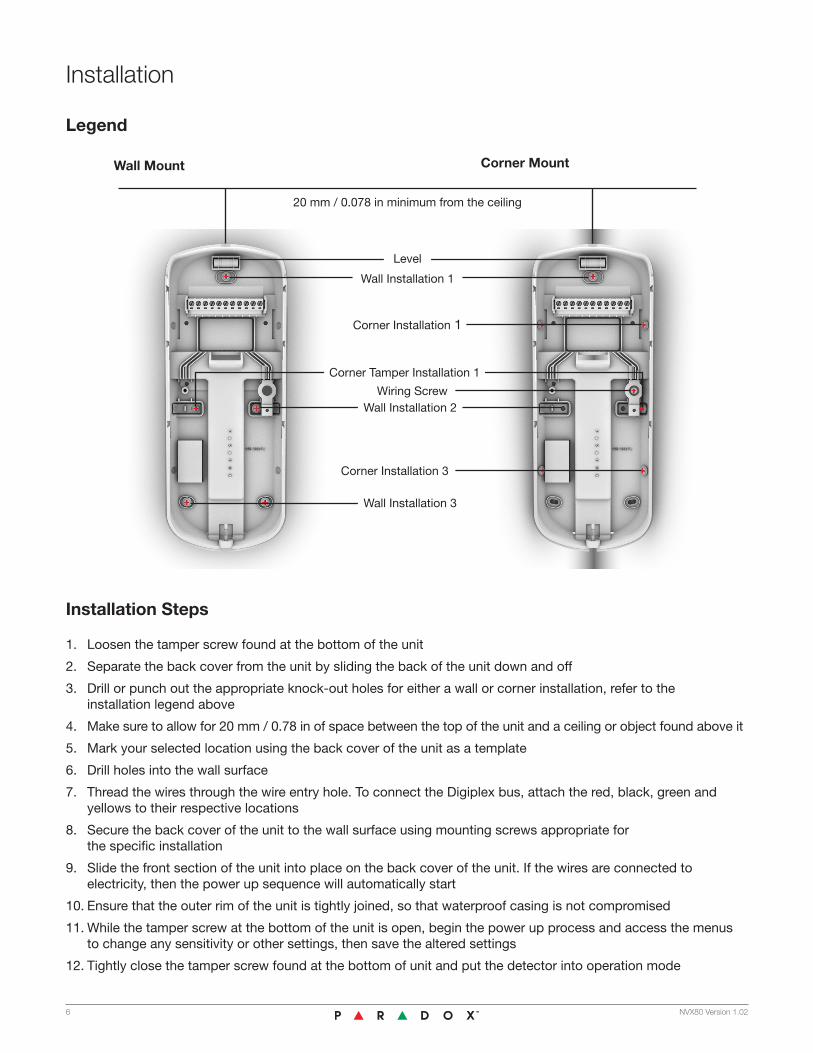
Installation Steps
1. Loosen the tamper screw found at the bottom of the unit
2. Separate the back cover from the unit by sliding the back of the unit down and off
3. Drill or punch out the appropriate knock-out holes for either a wall or corner installation, refer to the installation legend above
4. Make sure to allow for 20 mm / 0.78 in of space between the top of the unit and a ceiling or object found above it
5. Mark your selected location using the back cover of the unit as a template
6. Drill holes into the wall surface
7. Thread the wires through the wire entry hole. To connect the Digiplex bus, attach the red, black, green and yellows to their respective locations
8. Secure the back cover of the unit to the wall surface using mounting screws appropriate for the specific installation
9. Slide the front section of the unit into place on the back cover of the unit. If the wires are connected to electricity, then the power up sequence will automatically start
10. Ensure that the outer rim of the unit is tightly joined, so that waterproof casing is not compromised
11. While the tamper screw at the bottom of the unit is open, begin the power up process and access the menus to change any sensitivity or other settings, then save the altered settings
12. Tightly close the tamper screw found at the bottom of unit and put the detector into operation mode
Legend
Wall Mount Corner Mount
6 NVX80 Version 1.02
20 mm / 0.078 in minimum from the ceiling
Level
Wall Installation 1
Corner Installation 1
Corner Tamper Installation 1
Wall Installation 2
Wall Installation 3
Wiring Screw
Corner Installation 3
Installation

Installation Do’s & Don’ts
Do
• Do ensure that the unit’s detection beams are perpendicular to the anticipated movement
• Keep a minimum distance between adjoining NVX80 detectors to prevent MW cross interference, see the beam pattern diagram (see page 4)
• Do place the unit under a roof, or awning or use our all-weather cover, during an outdoor installation
• Do install the detector within the suggested range: installing the unit lower than 2.5 m / 8 ft 2 in may compromise the Pet Immunity capability, installing over 3.0 m / 9 ft 8 in may require use of our swivel bracket adjusted downward shifting the Pet Immunity beam and neutralizing the creep zone. Installing the unit over 3.0 m / 10 ft does not affect the creep zone.
Don’t
• Don’t direct the unit’s beams into swaying trees or bushes
• Don’t place the detector facing direct sunlight or near a heat source, as it might interfere with the Active IR anti-mask feature
• Don’t place any objects, such as shelves, ledges or plants, below the unit
• Don’t place any reflective objects within 2 m / 6 ft 6 in of the unit, as this may interfere with the MW anti-mask capabilities
NVX80 Version 1.027
In order to maximize detection efficiency, choose a location that is most likely to intercept intruders moving across the coverage area at a 45 degree angle.
Mounting Considerations
The optimal installation height for the NVX80 is 2.5 m to 3.0 m (8 ft 2 in to 10 ft).
2.5 m - 3.0 m(8'2'' - 10')
Avoid installing the detector near moving objects (e.g., swaying trees, bushes, etc.).
whether
If the installation site is near heavy traffic or objects beyond the required detection range, adjust the MW sensitivity and/or tilt the detector down.

Connecting to the Bus
Connecting to the Digiplex bus is quite straight forward. The red, black, green and yellow wires must be placed into the red, black, green and yellow slots, respectively.
8 NVX80 Version 1.02

Menu-Driven Settings and Configuration
The NVX80 introduces a unique 4-button interface and full-color OLED display screen. The NVX80 is completely menu-
driven, making programming and configuration simple. There are no jumpers, trimmers or complex wiring to contend with.
The OLED screen displays a variety of icons which indicate the current state of the detector. Alarm, pre-alarm,
and anti-mask events as well as notifications are displayed on the OLED. The menus provide direct control of the
detector’s operation, the sensitivity level settings, display characteristics and more.
To protect against malicious activity, the NVX80’s menus and button interface are active only when the tamper
screw at the bottom of the unit is open. The menus and button interface become functional only after a tamper
event is issued.
Installation specific settings can be saved and restored if altered. Settings can also be reset to factory defaults, all
with the push of a button.
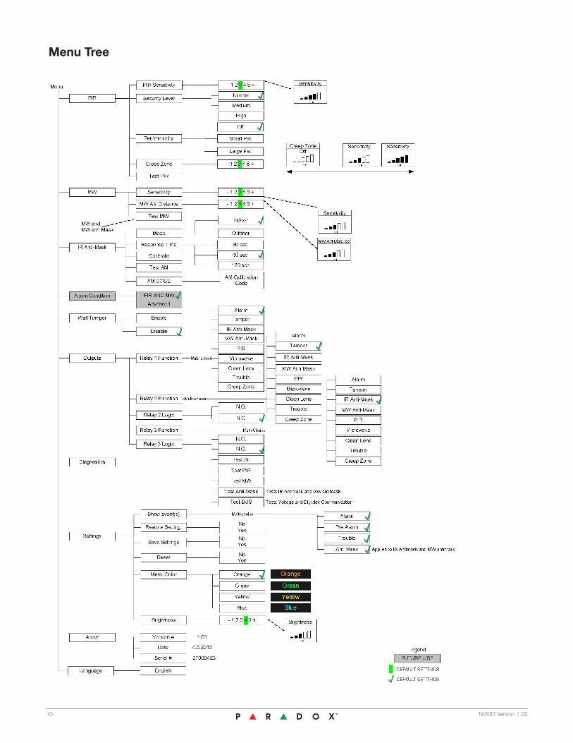
The following items are included in the NVX80 main menu: PIR, Microwave, Anti-Mask, Alarm Condition, Input,
Output, Diagnostics, Settings, About and Language. Via the menu these features can be activated, sensitivities set
and tested, input and outputs can be defined and product information can be viewed.
OK
used to enter and confirm selections
Down / Up
used to scroll through menus and increase/decrease sensitivity
Back
used to return to a previous menu, cancel without making changes and to exit the test mode
PIR Set and test PIR modes and sensitivity
Microwave (MW) Set and test MW sensitivity and MW anti-mask
IR Anti-Mask Set, calibrate and test anti-mask function
Alarm Condition Set the combination logic of PIR and MW Currently supports only PIR and MW
Wall Tamper Control tamper input settings
Outputs Define functionality of the relays
Diagnostics Test the detectors settings and bus operation
Settings Control display options, enable/disable notifications, save, restore or reset settings to factory defaults
About Shows the detectors firmware version, serial number and BUS zone number
Language Currently English only
Main Menu
Menus
NVX80 Version 1.02 9
10 NVX80 Version 1.02
Menu Tree
NVX80 Version 1.02 11
Outputs and Wall Tamper In (Input)
Power Up
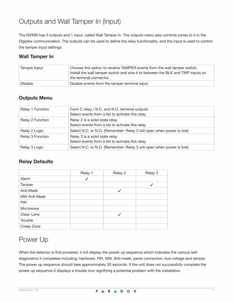
The NVX80 has 3 outputs and 1 input, called Wall Tamper In. The outputs menu also controls zones to 4 in the
Digiplex communication. The outputs can be used to define the relay functionality, and the input is used to control
the tamper input settings.
Wall Tamper In
Tamper Input Choose this option to receive TAMPER events from the wall tamper switch. Install the wall tamper switch and wire it to between the BLK and TMP inputs on the terminal connector.
Disable Disable events from the tamper terminal input.
Outputs Menu
Relay 1 Function Form C relay / N.C. and N.O. terminal outputsSelect events from a list to activate this relay
Relay 2 Function Relay 2 is a solid state relaySelect events from a list to activate this relay
Relay 2 Logic Select N.C. or N.O. (Remember: Relay 2 will open when power is lost)
Relay 3 Function Relay 3 is a solid state relaySelect events from a list to activate this relay
Relay 3 Logic Select N.C. or N.O. (Remember: Relay 3 will open when power is lost)
Relay Defaults
Relay 1 Relay 2 Relay 3
Alarm 3
Tamper 3
Anti-Mask 3
MW Anti-Mask
PIR
Microwave
Clean Lens 3
Trouble
Creep Zone
When the detector is first powered, it will display the power up sequence which indicates the various self-
diagnostics it completes including; hardware, PIR, MW, Anti-mask, panel connection, bus voltage and tamper.
The power up sequence should take approximately 30 seconds. If the unit does not successfully complete the
power up sequence it displays a trouble icon signifying a potential problem with the installation.

Settings
Diagnostics
Show Event(s) Select the events to be displayed on the OLEDNote: Selection do not affect the operation, only the displayAlarm - Alarms are shownPre Alarms - Pre Alarms (MW, PIR, Creep) are shownTrouble - Trouble events are shownAnti-Mask - Anti-mask events
Restore Settings Restore detector settings that were previously stored by ‘‘Save Settings’’ option
Save Settings Save detector settings
Reset Reset all detector settings to factory defaults
Menu Color Select menu color for better visibility and fun!
Brightness Select the general brightness of indicationsNote: The menu is always shown on maximal brightness except for the brightness screen which demonstrates the chosen brightness
Installation specific settings can be saved and restored if altered. Settings can also be reset to factory defaults, all
with the push of a button. Setting changes occur once the “OK” button is pushed. Changes will not be saved if the
“back” button is pushed.
Diagnostics Menu Action
Test All Tests all detection functionsShows PIR, MW and Anti-Mask notificationsThe blue frame does not appear in this mode
Test PIR Tests PIR detectionShows PIR detection and Creep Alarm
Test MW Tests and shows MW and MW anti-mask detection
Test Anti-Mask Tests Active IR and MWThe blue frame does not appear in this mode
Test Bus Tests voltage and Digiplex communicationsShows the measured bus voltageShows the status of data and clk linesOk for valid connectionN/A for no connection or invalid operation
Use the built-in diagnostics to pinpoint troublesome installations. Test the NVX80 detector settings and bus operation.
The Test Bus option will test the bus voltage and Digiplex connection, by checking the status of data and clk lines reporting no connection or invalid operation.
You can test the PIR, MW and Anti-Mask functionality separately or as a group.
12 NVX80 Version 1.02
Anti-Masking
IR Anti-Masking Menu Action
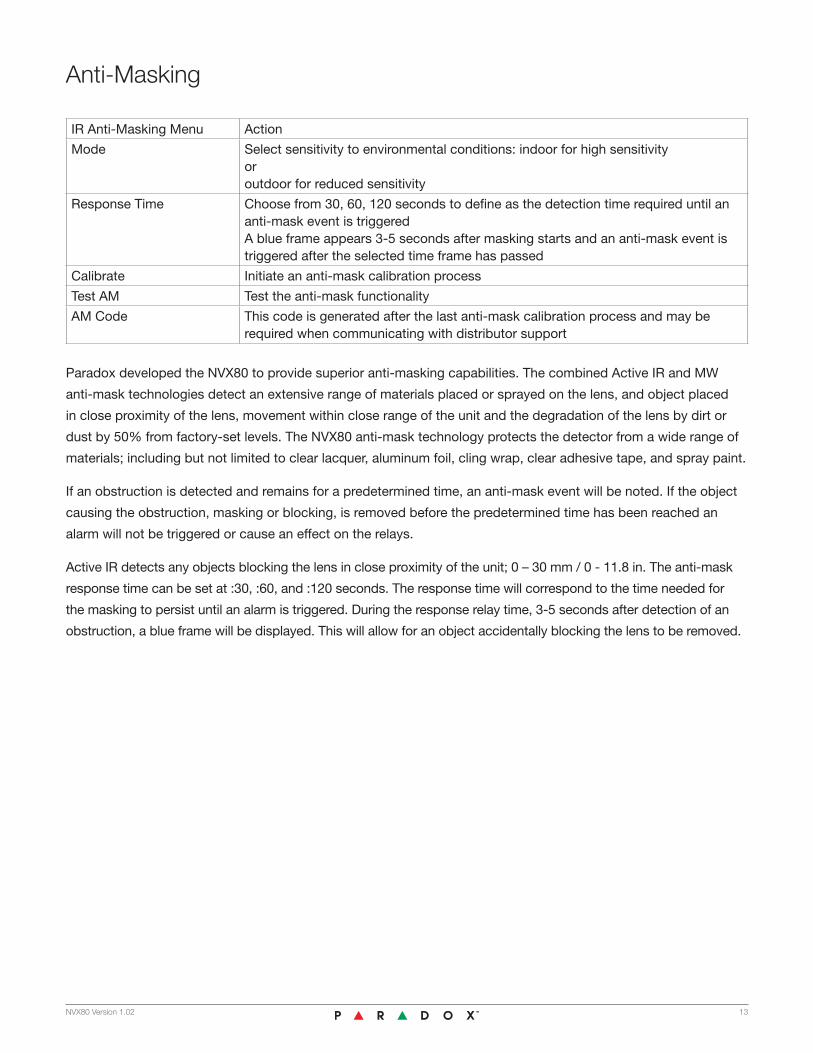
Mode Select sensitivity to environmental conditions: indoor for high sensitivity or outdoor for reduced sensitivity
Response Time Choose from 30, 60, 120 seconds to define as the detection time required until an anti-mask event is triggeredA blue frame appears 3-5 seconds after masking starts and an anti-mask event is triggered after the selected time frame has passed
Calibrate Initiate an anti-mask calibration process
Test AM Test the anti-mask functionality
AM Code This code is generated after the last anti-mask calibration process and may be required when communicating with distributor support
Paradox developed the NVX80 to provide superior anti-masking capabilities. The combined Active IR and MW
anti-mask technologies detect an extensive range of materials placed or sprayed on the lens, and object placed
in close proximity of the lens, movement within close range of the unit and the degradation of the lens by dirt or
dust by 50% from factory-set levels. The NVX80 anti-mask technology protects the detector from a wide range of
materials; including but not limited to clear lacquer, aluminum foil, cling wrap, clear adhesive tape, and spray paint.
If an obstruction is detected and remains for a predetermined time, an anti-mask event will be noted. If the object
causing the obstruction, masking or blocking, is removed before the predetermined time has been reached an
alarm will not be triggered or cause an effect on the relays.
Active IR detects any objects blocking the lens in close proximity of the unit; 0 – 30 mm / 0 - 11.8 in. The anti-mask
response time can be set at :30, :60, and :120 seconds. The response time will correspond to the time needed for
the masking to persist until an alarm is triggered. During the response relay time, 3-5 seconds after detection of an
obstruction, a blue frame will be displayed. This will allow for an object accidentally blocking the lens to be removed.
NVX80 Version 1.02 13

14 NVX80 Version 1.02
MW Anti-Mask Pre-Alarm in Test and Operation Mode
The NVX80 is built for harsh conditions, indoor or outdoor. Its anti-mask settings can be set to reduce sensitivity to
rain, wind and other inclement conditions.
The MW anti-mask feature detects motion within 0.5 m - 2 m / 1 ft 64 in - 6 ft 5 in from the unit.
The MW anti-mask is activated if a validated detection of movement has occurred during the 10 minutes prior to the
anti-mask detection. As the moving object nears the detector, the blue frame will appear on the OLED screen for 90
seconds. The MW anti-mask relay has not yet been activated. If an alarm is triggered as the result of the main lens’
detection of an object, during that same period, the blue frame will disappear and a MW anti-mask event will not occur.
If no alarm is triggered by detection of the main lens in the 90 second period, a MW anti-mask relay will be activated
and the MW anti-mask logo will be displayed. The MW anti-mask relay and logo will be cleared by an Alarm event
triggered by the main lens.
An Active IR anti-mask has a higher display priority. If Active IR and MW anti-mask events occur simultaneously,
then the blue frame will appear instead of a green frame and the Active IR anti-mask logo will appear instead of the
MW anti-mask logo. The resulting relays are not affected by the display priority.
The NVX80 features an OLED screen on which colorful icons are used to display alarm status, alarm type,
and notifications.
Pre-Alarms
When a movement signal is detected by within a PIR or MW range, the corresponding pre-alarm is shown.
The detector waits for 16 seconds for the complementary technology’s detection. If no additional movement is
detected during that time, the detector will return to its standby state.
Display Icons
Active IR Anti-Mask appears 3-5 seconds after detection of an obstruction in Test
Mode (Test All or Test Anti-Mask) and in rotation with the blue frame icon after the
predetermined response time is reached in Operation Mode.
Anti-Mask Notification appears, only in the Operation Mode, 3-5 seconds after an
obstruction is detected or in rotation with the Active IR Anti-Mask indicator after the
response time is reached.

NVX80 Version 1.02 15
PIR Pre-Alarm in Test Mode
MW Pre-Alarm in Test and Operation Mode
Alarms as shown in Test and Operation Mode after PIR and MW Pre-Alarm
PIR Pre-Alarm in Operation
MW Anti-Mask Pre-Alarm in Test and Operation Mode
Creep alarm as shown in Test and Operation Mode
Alarms
When an obstruction or movement has been detected and confirmed, the following alarm icons will be displayed.

Passive Infrared Detection with Independent Creep Zone
PIR Sensitivity Select sensitivity from 1 (lowest) to 5 (highest)The solid bars represent the current settingsThe frame represents your selectionUse the Up/Down buttons to toggle through the settingsPush OK to confirm the changePush Back to cancel any changes
Noise Rejection Control the level of rejection interferenceNormal - Indoor, regular and normalModerate - Industrial conditionsHarsh - Extreme conditions (bad weather, machinery, etc.)
Pet Immunity OffUp to 10 kg (22 lbs) - Small PetUp to 15 kg (33 lbs) - Medium PetUp to 20 kg (44 lbs) - Large Pet
Creep Zone Select Creep Zone sensitivity 1 (lowest) to 5 (highest)1 for 2.5 m installations5 for 3.5 m installations
Test PIR Test the PIR functionalityShow only PIR and Creep Zone indications
At an installation height within the suggested range of 2.5 m – 3.5 m / 8 ft 2 in – 11 ft 6 in, infrared detection is
possible up to 17 m / 5 ft 6 in. Detection is at 90 degrees.
The creep zone is exceptionally large. The NVX80 delivers approximately a 180 degree angle covering almost 2 m /
6 ft 7 in in all directions in front of the detector. When the Pet Immunity is activated, the creep zone is neutralized.
Creep alarm as shown in Test and Operation Mode
16 NVX80 Version 1.02

Microwave (MW)
Alarm Condition
Pet Immunity
MW and PIR Both MW and PIR are required for ALARMCreep Zone detection creates an ALARM, without waiting for MW
Reserved Coming soon
The PIR detection and the microwave detection can be activated alone or in conjunction with the other capabilities.
When setting an output to microwave or PIR only, the relay delays may be as quick as 10 seconds. This should be
noted when performing walk tests, as the relay delay may extend to as long as you keep walking or a maximum of
30 seconds.
Pet Immunity Set for small or large pets
The NVX80’s Pet Immunity can filter out the movement small and large animals, up to 20 kg / 44 lbs in both indoor
and outdoor environments. By ignoring the movement of the pets the detector’s reliability increases.
MW Sensitivity Select sensitivity from 1 (lowest) to 5 (highest)Push OK to confirm the changePush Back to cancel any changes
MW AM Distance Control MW anti-mask sensitivity, range of 0.5 m to 2 m
Test MW Test the MW functionalityShows only MW and MW ‘‘anti-mask’’ indications
The microwave coverage varies depending upon the chosen sensitivity setting. The coverage range is
approximately effective within 10 m – 19 m / 33 ft 3 in – 62 ft 3 in and up to 110 degrees. The greater the sensitivity
setting results in a larger range of coverage.
Sensitivity Setting Range
3 12 m / 39 ft 4 in
4 15 m / 49 ft 2 in
5 17 m / 55 ft 8 in
NVX80 Version 1.02 17

18 NVX80 Version 1.02
Appears when the tamper screw at the bottom of the unit is open and that the
menus are not accessible. This message will also appear at the end of the power
up sequence.
Appears when the Wall Tamper screw has been disengaged. This message will
also appear after the Power Up sequence is finished, should the Wall Tamper
screw be open during power up. The detector will enter menu mode after the
power up sequence is over.
After closing the Wall Tamper, this message will appear.
When any of the tampers are detected as open, a relay configured as a Tamper will trigger. The wall tamper switch
can be excluded from this relay sequence by disabling it in the Input menu.
Tamper
Tamper messages are triggered by when the tamper screw at the bottom of the unit is opened or the wall tamper
screws have been disengaged.
Appears when the tamper screw at the bottom of the unit is tightly closed.
It signifies that the unit has entered operation

NVX80 Version 1.02 19
Appears in Operation Mode when the unit’s voltage is below 10v. It may also appear
after an alarm or at the end of the power up sequence if the voltage was low.
The Test Bus tool, reached in the Diagnostics Menu, can be used to discern the
unit’s current voltage.
Appears in Operation Mode when a strong light source is in front of the unit.
Appears in Operation Mode when the unit detects a reduction in lens transparency,
i.e., below 50% of factory-set levels. If this condition exists, this message will
appear at the end of the power up sequence.
Appears in Operation Mode if any of the Digiplex wires are disconnected or invalid.
This message will appear only once at the end of the power up sequence. Once the
Digiplex bus is connected properly, this message will only appear if it is once again
disconnected or invalid.
Soon to be activated
The following notifications appear when the functionality of the NVX80 unit is compromised. These indicators can
help troubleshoot during installation or during operation.
Notifications
About Us
Firmware Upgrades
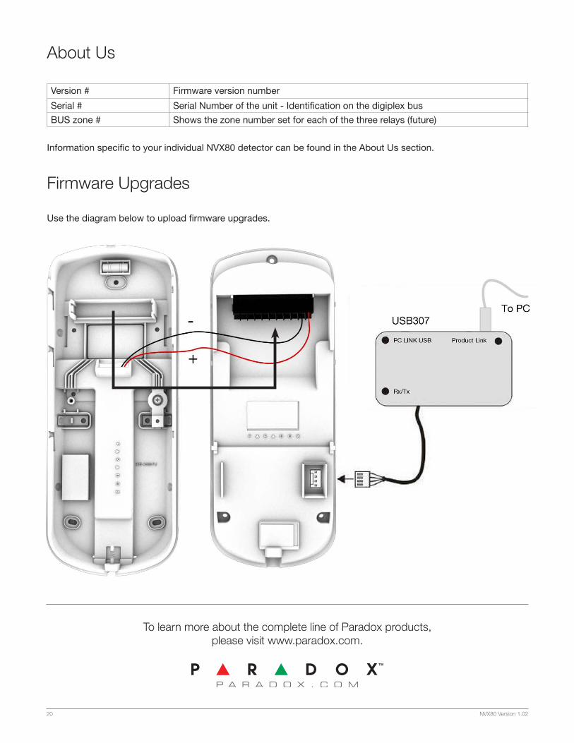
Version # Firmware version number
Serial # Serial Number of the unit - Identification on the digiplex bus
BUS zone # Shows the zone number set for each of the three relays (future)
Information specific to your individual NVX80 detector can be found in the About Us section.
Use the diagram below to upload firmware upgrades.
To learn more about the complete line of Paradox products, please visit www.paradox.com.
20 NVX80 Version 1.02