numerical modeling of radiative heat transfer in water...
TRANSCRIPT

PAPER V
Numerical modeling of radiative heat transfer in water sprays
In: Fire Safety Journal 2006. Vol. 41, No. 1, pp. 76–86. Copyright Elsevier 2006.
Reprinted with permission from the publisher.
ARTICLE IN PRESS
0379-7112/$ -
doi:10.1016/j.
Correspon
Fire Safety Journal 41 (2006) 76–86
www.elsevier.com/locate/firesaf
Numerical modeling of radiative heat transfer in water sprays
Simo Hostikkaa,, Kevin McGrattanb
aVTT Building and Transport, Technical Research Centre of Finland, FI-02044 VTT, FinlandbBuilding and Fire Research Laboratory, National Institute of Standards and Technology, Gaithersburg, MD 20899, USA
Received 28 February 2005; received in revised form 10 August 2005; accepted 1 September 2005
Available online 21 November 2005
f
Abstract
A numerical method is developed for the transport of polychromatic radiation in polydisperse sprays. The method is implemented
within a wide-band radiation solver using the Finite Volume Method. Mie theory is used to compute the absorption and scattering
characteristics of the water droplets. The solver is designed to be computationally effective because the simulations of fire scenarios are
inherently time-dependent and the radiative transport equation must be solved many times. The model is compared with two sets o
experimental data, and a discussion of the results is presented.
r 2005 Elsevier Ltd. All rights reserved.
Keywords: Water sprays; Radiation model; Scattering calculation; Lagrangian droplets
t
l
,
ft
.
l
,-
.
f
t
1. Introduction
Thermal radiation plays a very important role in thedevelopment of fires by preheating combustible materialsahead of the flame front. This preheating increases the rateof flame spread, often causing ignition of surfaces withoudirect flame impingement. Water-based fire suppressionsystems, like sprinklers and water mist, can reduce the rateof fire spread by blocking thermal radiation. Also, firefighters use water spray to protect themselves from thermaradiation during assaults on burning buildings.
Water droplets attenuate radiation by absorption andscattering. The relative importance of these mechanismsdepends on the droplet size and the wavelength of theradiation. For the fire protection performance of the spraythe geometrical dimensions and water density of the sprayare also important. To simulate the radiation transfer inwater sprays, one needs to calculate both the transport oenergy and the optical properties of the spray. The simplestechnique to calculate the transport of energy is to useLambert–Beer law which assumes that the droplets aretotally absorbing or the scattering can be excludedRavigururajan and Beltran [1] used Lambert–Beer lawfor the transport and simple correlations for the optica
f.
see front matter r 2005 Elsevier Ltd. All rights reserved.
firesaf.2005.09.003
ding author. Tel.: +358 20 722 4839; fax: +358 20 722 4815.
V/
properties of the droplets to find the optimum droplet sizefor the attenuation of fire radiation. Since the assumptionof pure absorption is not valid in most practical problemsmore advanced schemes such as two-flux model [3–6], sixflux model [7] and discrete ordinates method (DOM) orfinite volume method (FVM) [8–13] have been developedMie theory is typically used for the calculation of theoptical properties [2]. It is generally valid for spherical andisolated droplets. An early investigation of the efficiency olarge water droplets in the protection from heat radiationwas given by Thomas [3]. He derived the expressions forthe radiation transmissivity through the droplet cloudusing a two-flux model and the geometric optics. Coppalleet al. [4] used a two-flux model and simple approximationsof the droplet optical properties allowing for a fascomputation of the radiation flux through a layer of watermist. Log [5] used the method of Coppalle et al. to calculatethe attenuation of radiation in polydisperse water sprays byassuming that the attenuation effects of the droplet sizegroups are additive by nature. Yang et al. [6] used Mietheory for the calculation of the absorption and scatteringcoefficients and scattering phase functions of the waterdroplets. The spectrally resolved optical properties of waterdroplets were incorporated into the two-flux model. Themodel was used to predict the radiation penetration oa monodisperse water mist at different wavelengths
1

KadtdaiatcoiflrbsflettC4dwm[fossai
aaftTfi
rtMnacrSelrt
iMttdtpota
2
2
sd(dTmewFt
ARTICLE IN PRESS
Nomenclature
d droplet diameter, mf normalized droplet number density functionI total intensity, Wm2 sr1
Il monocromatic intensity, Wm3 sr1
r droplet radius, ms direction vectorx position vectorU combined total intensity, Wm2
Greek symbols
O solid angle, srF scattering phase function
wf fraction of forward scatteringf azimuthal anglel wavelength, mk absorption coefficient, m1
s scattering coefficient, m1
y polar angle
Subscripts
b blackbodym meann band-specific
S. Hostikka, K. McGrattan / Fire Safety Journal 41 (2006) 76–86 77
eramida et al. [7] used a six-flux model to predict thettenuation in polydisperse water mist. Contributions ofifferent droplet sizes were taken into account by summinghe coefficients of a monodisperse spray over the localroplet size distribution. Berour et al. [8] used Mie theorynd DOM to investigate the performance of water curtainsn fire protection. By stationary simulations of both mono-nd polydisperse water sprays in two-dimensional geome-ry, they studied the effects of droplet size and waterurtain thickness on the transmittance and energy balancef the water curtain. Jinbo et al. [9] studied the effect ofsotropic scattering approximation on the radiative heatuxes and temperatures in stationary two-dimensionalectangular media. By comparing the FVM results againstenchmark solutions, they concluded that the anisotropiccattering has stronger effect on the relative error of heatux than the temperature profiles inside the media. Trivict al. [10] coupled the Mie theory with FVM and studiedhe radiative transport in monodisperse particle clouds inwo dimensions. Similar coupling was made for DOM byolling et al. [11]. They divided the radiation spectrum to3–367 bands and solved the RTE for each band in a two-imensional domain to investigate the performance ofater curtains. The use of gray assumption for radiation inonodisperse particle clouds was studied by Consalvi et al.
12]. They also coupled the Mie theory with FVM, andound that the gray model provided correct results for anptical thickness less than 2. The reduction of falsecattering was studied in one-dimensional, anisotropicallycattering media by Liu et al. [13]. The false scatteringppears in the numerical approximation of the in-scatter-ng integral in DOM and FVM methods.All of the above models have features that limit their
pplicability on practical fire simulations. Although the onend two-dimensional geometries provide good environmentor generation of general rules, like those for water curtains,he practical fire scenarios are always three-dimensional.he same applies for stationary models; the simulations ofre scenarios are inherently time-dependent, and the
V/2
adiation transport equation must be solved thousands ofimes for a given scenario. In addition, the coupling of theie theory and radiation transport scheme should simulta-eously consider the whole spectrum of thermal radiationnd distribution of different droplet sizes. The realhallenge of the fire model development is to consider theseequirements while retaining the computational efficiency.ince radiation typically accounts for about one-third of thenergy transport in fires, convection making up the rest, it isogical to require that the computational cost of theadiation solution should not exceed roughly one-third ofhe overall cost of the calculation.In this work, a wide-band radiation solver using FVM is
mplemented within a large eddy simulation fire model.ie theory is used to compute the radiative properties of
he water droplets. The radiative properties of the spray arehen computed by averaging the properties of individualroplets over the spectrum and the droplet size distribu-ion. For the fast computation, the spray radiativeroperties are pre-computed and tabulated as functionsf the mean droplet diameter. A simple approximation ofhe scattering integral is developed to account for thenisotropic scattering.
. Model description
.1. Large eddy simulation fire model
The radiation solver and the droplet algorithms de-cribed in this paper have been incorporated into fireynamics simulator (FDS), a computational fluid dynamicsCFD) model of fire-driven fluid flow. The software iseveloped at the National Institute of Standards andechnology in co-operation with VTT (Finland). Theodel solves numerically a form of the Navier–Stokesquations appropriate for low-speed, thermally-driven flowith an emphasis on smoke and heat transport from fires.DS uses a large eddy simulation (LES) model forurbulence. Unlike most Reynolds-averaged Navier stokes

.
-
l
-
)
.f
f
-
t
Þ
-
.
t
Þ
.
)
f
l
)
)
f
l
Þ
ARTICLE IN PRESSS. Hostikka, K. McGrattan / Fire Safety Journal 41 (2006) 76–8678
(RANS) solvers, the LES model solves the time scales of theturbulent eddies and therefore requires the small time stepsbound by the CFL (Courant, Freidrichs, Lewy) conditionA full description of the model is given in Ref. [14].
2.2. Water droplets
The water spray is modelled as a Eulerian–Lagrangiansystem, where the gas phase is solved using a Eulerianmethod and the liquid phase is tracked as numerousLagrangian particles with mass, momentum and temperature. The Eulerian–Lagrangian approach is currently used inmost multidimensional spray simulations because it is simpleto implement and computationally efficient [15]. Eachdroplet, or ‘‘parcel’’, represents a large number of actuadroplets. For the statistical representation of the spray, theproperties of the parcels are randomly chosen from the givendroplet size and velocity distributions. The initial droplet sizedistribution is expressed in terms of its cumulative volumefraction (CVF), a function that relates the fraction of thewater volume (mass) transported by droplets less than agiven diameter. The CVF is here represented by a combination of log-normal and Rosin–Rammler distributions [16]
F ðdÞ ¼
1ffiffiffiffiffiffi2pp
Z d
0
1
s d 0e½lnðd0=dm Þ
2
2s2 dd 0 ðdpdmÞ;
1 e0:693d
dmð Þg
ðdmodÞ;
8><>: (1
where dm is the median droplet diameter, and g and s areempirical constants equal to about 2.4 and 0.6, respectivelyA stratified sampling technique is used for the sampling othe droplets to avoid tracking too many of the numerous tinydroplets and too few of the less numerous larger droplets. Inthis technique, the range of droplet diameters is divided intoa discrete number of intervals. The number of samples fromeach interval is the same, but the droplets are given weightsbased on the total volume of the interval. In this work, fiveintervals are used.
2.3. Wide band model for radiation
The attenuation of radiation is a well-known feature owater (and other) sprays. The attenuation is caused byabsorption by the droplets and scattering. The radiationdroplet interaction must therefore be solved for both theaccurate prediction of the radiation field and the dropleenergy balance. The radiative transport equation (RTE) forspectral intensity Il passing through an absorbing/emittingand scattering medium is
s rIlðx; sÞ ¼ klðxÞ þ slðxÞ½ Ilðx; sÞ þ klðxÞIbðx; lÞ
þslðxÞ4p
Z4pFðs; s0ÞIlðx; s0ÞdO0, ð2
where Ib is the blackbody source function and Fðs; s0Þ is thescattering phase function giving the scattered intensityfrom direction s0 to s. Although the emission of waterdroplets is usually much smaller than the absorption, it is
V/
included in the model for consistency and energy conservation. The gas phase absorption and emission are hereneglected for simplicity but included in the computationsThe computation of the gas phase radiative properties isexplained in Ref. [17].In practical simulations the spectral dependence canno
be solved accurately. Instead, the radiation spectrum isdivided into a relatively small number of bands, and aseparate RTE is derived for each band by integratingEq. (2) over the band. The band specific RTEs are
s rInðx; sÞ ¼ knðxÞ þ snðxÞ½ Inðx; sÞ þ knðxÞIb;nðxÞ
þsnðxÞ
4p
Z4pFðs; s0ÞInðx; s
0ÞdO0, ð3
where kn is the mean absorption coefficient inside the bandThe source term can be written as a fraction of theblackbody radiation
Ib;n ¼ F nðlmin; lmaxÞsT4i =p, (4
where s is the Stefan–Boltzmann constant and lmin andlmax are the limits of the n’th band. The calculation ofactors Fn is explained in Ref. [2]. When the integratedintensities corresponding to the bands are known, the totaintensity and combined total intensity are calculated bysumming over all the bands
Iðx; sÞ ¼XNb
n¼1
Inðx; sÞ, (5
UðxÞ ¼XNb
n¼1
UnðxÞ ¼XNb
n¼1
Z4p
Inðx; sÞdO. (6
To include the most important absorption bands owater and CO2, the most important gaseous species in firesimulations, six radiation bands are used. The limits of thebands are shown in Table 1. Even with a reasonably smalnumber of bands, the solution of Nb RTEs is very timeconsuming. Fortunately, in most large-scale fire scenariossoot is the most important combustion product controllingthe thermal radiation from the fire and hot smoke. As theradiation spectrum of soot is continuous, a gray gasbehaviour can be assumed (Nb ¼ 1).
2.4. Averaging over the droplet size distribution
The local absorption and scattering coefficients arefunctions of the local droplet size distribution:
klðxÞ ¼Z 10
Nðr;xÞCaðr; lÞdr,
slðxÞ ¼Z 10
Nðr;xÞCsðr; lÞdr, ð7
where Nðr;xÞ is the number of droplets having radiusbetween r and rþ dr at position x. The absorption andscattering cross sections, Ca and Cs, are calculated usingMie theory. In practical simulations, it is impossible toperform these integrations at each position at every time
3

sdpp
N
add
k
s
Fa
k
s
wuwpaa
sapioaradia
d
2
tc
siwcHaWW
U
wlm
wosd
s
BR
s
wt
iPcTr
e
w
ARTICLE IN PRESS
Table 1
Limits of the spectral bands for a 6-band model.
Band 1 2 3 4 5 6
Soot CO2 Soot CO2 H2O, Soot
Major Species H2O, Soot Soot Soot
n (1/cm) 10000 3800 3400 2400 2174 1000 50
l (mm) 1.00 2.63 2.94 4.17 4.70 10.0 200
S. Hostikka, K. McGrattan / Fire Safety Journal 41 (2006) 76–86 79
tep. Instead, we assume that the local droplet numberensity function has the same functional form regardless ofosition, with only the mean diameter varying from point tooint. The local size distribution can now be expressed by
ðr;xÞ ¼ N 0ðxÞf ðr; dmðxÞÞ (8)
nd the local absorption and scattering coefficients can beetermined by averaging over the initial droplet sizeistribution function
lðxÞ ¼ N 0ðxÞ
Z 10
f ðr; dmðxÞÞCaðr; lÞdr,
lðxÞ ¼ N 0ðxÞ
Z 10
f ðr; dmðxÞÞCsðr; lÞdr. ð9Þ
or the numerical implementation, it is useful to write thebove equation in the form
lðxÞ ¼ AdðxÞ
Z 10
f ðr; dmðxÞÞCaðr; lÞ
pðdmðxÞ=2Þ2
dr,
lðxÞ ¼ AdðxÞ
Z 10
f ðr; dmðxÞÞCsðr; lÞ
pðdmðxÞ=2Þ2
dr, ð10Þ
here Ad is the total cross sectional area of the droplets pernit volume. We approximate AdðxÞ rdðxÞ= 2rwdmðxÞ=3
,
here rw is the density of water and rdðxÞ is the water masser unit volume, which is provided by the droplet trackinglgorithm. The integrals of Eq. (10) can be calculated indvance and stored in tables for different values of dm.The absorption and scattering cross sections and the
cattering phase function are calculated using the ‘‘MieV’’lgorithm developed by Wiscombe [18]. The opticalroperties of water are taken from Ref. [19]. Mie theorys generally valid for homogenous isotropic sphericalbjects embedded in a homogenous, isotropic, dielectricnd infinite medium. As the current work considerselatively low speed droplets in air, most of the abovessumptions are valid. The interference between theroplets can be neglected when the center to center spacings more than about 3 diameters. In terms of mean diameternd average spacing the interference condition is
mðxÞffiffiffiffiffiffiffiffiffiffiffiffiN 0ðxÞ3
po
1
3. (11)
.5. Approximation of the scattering integral
An accurate computation of the in-scattering integral onhe right-hand side of Eq. (2) would be extremely timeonsuming. It is here approximated by dividing the total 4p
V/4
olid angle into a ‘‘forward angle’’ dOl and the correspond-ng ‘‘ambient angle’’ dO ¼ 4p dOl . For compatibilityith the FVM solver, the forward angle is set equal to theontrol angle resulting from the angular discretization.owever, the forward angle is assumed to be symmetricbout the center of the corresponding control angle.ithin the forward angle dOl , the intensity is Ilðx; sÞ.ithin the ambient angle, it is approximated as
lðxÞ ¼
UlðxÞ dOl Ilðx; sÞ
dO(12)
here UlðxÞ is the combined spectral intensity at wave-ength l. The in-scattering integral can now be approxi-ated as
slðxÞ4p
Z4pFðs; s0ÞIlðx; s0ÞdO0
¼ slðxÞ½wfIlðx; sÞ þ ð1 wf ÞUlðxÞ, ð13Þ
here wf ¼ wf ðr; lÞ is a fraction of incoming intensityriginally within solid angle dOl that is scattered into theame angle dOl . An effective scattering coefficient is nowefined as
¯ lðxÞ ¼4pAdðxÞ
4p dOl
Z 10
f ðr; dmðxÞÞ 1 wf ðr; lÞ Csðr; lÞ
pdmðxÞ2=4
dr.
(14)
y using the above definition of slðxÞ and integrating theTE over the spectrum we get a band-specific RTE
rInðx; sÞ ¼ knðxÞ þ snðxÞ½ Inðx; sÞ þ knðxÞIb;nðxÞ
þsnðxÞ
4pUnðxÞ, ð15Þ
here the source function is based on the average dropletemperature within a cell.During the simulation, the local values of kn and sn are
nterpolated from one-dimensional tables using dmðxÞ. Alanck spectrum, used in the wavelength averaging, isalculated using some appropriate value for temperature.his ‘‘radiation temperature’’ T rad should be selected toepresent the temperature of a radiating flame.A formula for wf was previously derived by Yang
t al. [6].
f ðr; lÞ ¼1
dOl
Z mx
0
Z mx
0
Z md;p
md;0
P0ðydÞ
1 m2Þð1 m02Þ ðmd mm0Þ2 dmddmdm0, ð16Þ

)
ttt
)
Þ
.t
f
.f
l
.
)
f
)
.
)
ftf
ARTICLE IN PRESSS. Hostikka, K. McGrattan / Fire Safety Journal 41 (2006) 76–8680
where md is a cosine of the scattering angle yd and P0ðydÞ isa single droplet scattering phase function
P0ðydÞ ¼l2 jS1ðydÞj2 þ jS2ðydÞj2
2Csðr; lÞ(17
and S1ðydÞ and S2ðydÞ are the scattering amplitudes, givenby Mie theory. When wf is integrated over the droplet sizedistribution in Eq. (14), it is multiplied by Csðr; lÞ. It istherefore jS1j
2 þ jS2j2, not P0ðydÞ, that is integrated. Some
examples of phase function P0ðydÞ are shown in Fig. 1, adifferent values of droplet size parameter X 2pr=l. Asmall values of X the phase function is almost constanover the scattering angle, and at high values the (largedroplets, small wavelength) the energy is scattered close tothe forward direction.
The integration limit mx is the cosine of the polar angledefining the boundary of the symmetric control angle dOl
mx ¼ cosðylÞ ¼ 1
2
NO, (18
where NO is the total number of control angles. The limitsof the innermost integral are
md;0 ¼ mm0 þffiffiffiffiffiffiffiffiffiffiffiffiffi1 m2
p ffiffiffiffiffiffiffiffiffiffiffiffiffiffi1 m02
q,
md;p ¼ mm0 ffiffiffiffiffiffiffiffiffiffiffiffiffi1 m2
p ffiffiffiffiffiffiffiffiffiffiffiffiffiffi1 m02
q. ð19
One weakness of the modeling approach is that a higherNO does not always imply better accuracy, because less andless radiation is scattered into the forward control angleThat is, the direction information of the scattered energy aangles y4yl is lost, and the energy is divided evenly overthe ambient angle dO.
2.6. Numerical solution of RTE
The radiative transport (3) is solved using the finitevolume method (FVM) for radiation [20]. The intensitieson the cell boundaries are calculated using a first order
t
t
f
t
.
,
t
10-2 10-1 10010-2
100
102
104
θd
P (
θ d)
0.83
2.8
6
15
82
2π r/λ
Fig. 1. Normalized unpolarized phase function of a single droplet.
V/
upwind scheme. The solution method of the discretizedRTE is based on an explicit marching sequence [21], wherethe physical space is swept in the propagation direction othe intensity and the intensities can be solved explicitlyfrom an algebraic equation. Iterations are needed only toaccount for the reflective boundaries and scatteringHowever, this is seldom necessary in practice, because othe small time step needed by the fluid flow solver.The spatial discretization for the RTE solver is the same
as for the fluid solver. The distribution of the angles isbased on empirical rules that attempt to produce equacontrol angles dOl ¼ 4p=NO, where NO is the number givenby the user. The polar angle, y, is first divided into Ny
bands, where Ny is an even integer. Each y-band is thendivided into NfðyÞ parts in the azimuthal (f) directionNfðyÞ must be divisible by 4. The number of y-bands is
Ny ¼ 1:17 N1=2:26O (20
rounded to the nearest even integer. The number of-angles on each band is
NfðyÞ ¼ maxf4; 0:5NO ½cosðyÞ cosðyþÞg (21
rounded to the nearest integer divisible by 4. y and yþ arethe lower and upper bounds of the y-band, respectivelyFinally, the exact NO is calculated as
NO ¼XNy
i¼1
NfðyiÞ. (22
The angular discretization is symmetric with respect tothe planes x ¼ 0, y ¼ 0, and z ¼ 0. This symmetry hasthree important benefits: first, it avoids the problemscaused by the fact that a first order upwind scheme is morediffusive in non-axial directions. Second, the treatment osymmetric boundaries becomes very simple. Third, iavoids so-called ‘‘overhang’’ situations, where the sign othe intensity direction vector components is changed insidethe control angle. These ‘‘overhangs’’ can make the systemof linear equations more complicated.Computational cost is always an issue in time-dependen
simulations, especially in simulations that are bound by theCFL condition. To reduce the cost of the radiationsolution, the radiation solver is typically not called aevery time step of the hydrodynamic solver. For time stepswhere the radiation is not being updated, only the radiativeloss term must be updated to maintain the time accuracy othe energy equation. More savings can be achieved byupdating only a fraction of the control angles for a givencall to the radiation solver. The effect of this kind of cosreduction is demonstrated in Fig. 2. The upper figure showsthe time development of the combined total intensity U
inside a hydrocarbon pool flame in some arbitrary unitsFig. 2(b) shows similar results inside a water spray withexternal radiation source. Local gas temperature anddroplet diameter are shown for reference. As can be seenthe cost reduction has a slight time-averaging effect. Thesecost–saving measures should not be applied when the exac
5

tnpsa
3
3
casapfta
goð
mdir
3tphnt
m0md
umtramidb5ud
ifpdNrdtt
ARTICLE IN PRESS
0 0.5 1 1.5 20
0.2
0.4
0.6
0.8
1
Time (s)
U, T
∆Nt, ∆NΩ
Gas temperature
1, 1
1, 5
3, 5
0 0.5 1 1.5 2-0.2
0
0.2
0.4
0.6
0.8
1
1.2
Time (s)
U, d
m
∆Nt, ∆NΩ
Mean droplet diameter
1, 1
1, 5
3, 5
(a)
(b)
Fig. 2. The effect of the temporal and angular increments on the
combined intensity in (a) pool flame and (b) water spray. The units are
arbitrary. The radiation solver is called every DNt time steps of the
hydrodynamic solver and every DNO control angles are updated per call.
HOTPLATE
0.7 m
NOZZLE
HEAT FLUXGAUGE
DROPLET SIZE MEAS.
2.2
m
1.5
m
4.0 m
1.0
m
Fig. 3. Schematics of the experiment of Murrel et al. [22].
S. Hostikka, K. McGrattan / Fire Safety Journal 41 (2006) 76–86 81
ime dependence of the turbulence-radiation interaction iseeded. Numerical experiments have shown that forractical fire simulations, calling the radiation every 3 timeteps and updating 1 out of 5 control angles per call givescceptable results.
. Results and discussion
.1. Large-scale experiment
The first validation test is the simulation of experimentonducted by Murrel et al. [22]. They measured thettenuation of thermal radiation passing through a waterpray using a heat flux gauge. The schematics of the systemre shown in Fig. 3. The radiation was produced by a heatanel, one meter square, at 900 C. The horizontal distancerom the radiation panel to the spray nozzle was 2m and tohe measurement point 4m. The nozzles were positioned atheight 0.24m above the panel upper edge. The heat flux
V/6
auge was positioned at the line passing through the centerf the panel. The attenuation of radiation was defined asq0 qsÞ=q0, where q0 is the initial radiative heat flux,easured without a spray, and qs is the heat flux measureduring the spray operation. The purpose of the simulations to compare the measured and simulated attenuation ofadiation at different flow conditions.The computational domain was 4m wide, 2m deep andm high. The vertical and top boundaries were open, andhe bottom of the domain was a solid floor. The nozzle wasositioned horizontally in the center of the domain ateight 2.24m. Three different nozzles were simulated. Eachozzle was a full-cone type industrial nozzle. The simula-ions were performed at eight different flow rates.In the experiments, Murrel et al. [22] did not measure theean droplet diameters in the vicinity of the nozzles, but.7m below the nozzle, i.e. at the height of the heat fluxeasurement point. The droplet size boundary condition
m (BC) was therefore determined by iterating dm (BC)ntil the simulated and measured mean diameters at theeasurement location were equal, with a few percentolerance. The iteration was performed for all nozzle-flowate combinations. The initial droplet size distribution wasssumed to have the functional form of Eq. (1). Theeasured and corresponding BC mean diameters are listed
n Table 2. For nozzle D, the measured mean dropletiameter increased with increasing pipe pressure Dp
etween 1 and 3 bar, and then dropped sharply betweenand 6 bar. The experimental results defy a commonlysed scaling relation for water droplets, which states that
m / Dp1=3 [23,24]. The measured mean diameters (shownn parentheses) were therefore replaced by values thatollow the trend found for nozzles A and B. For thearameters g and s controlling the width of the droplet sizeistribution, the default values 2.43 and 0.6 were used.umerical experiments showed that attenuation results areelatively insensitive to the small variations of g and s. Theroplet velocities on the inflow boundaries were set equalo the measured vertical velocity component 0.7m belowhe nozzle. At the chosen flow rates, the interference

.
f
t
-
)l
l
l
,
.t
ft
ARTICLE IN PRESS
Table 2
Boundary conditions of the A, B and D nozzles
Nozzle A Nozzle B Nozzle D
Dp Flow dm (exp.) dm (BC) Flow dm (exp.) dm (BC) Flow dm (exp.) dm (BC)
(bar) (L/min) (mm) (mm) (L/min) (mm) (mm) (L/min) (mm) (mm)
1 0.350 268 353 1.40 392 552 2.60 691 768
2 0.550 175 190 1.83 266 398 3.75 327 (753) 420
3 0.625 110 110 2.00 167 212 4.50 276 (794) 377
4 0.700 104 104 2.25 162 209 5.00 235 (638) 295
5 0.750 102 102 2.50 115 120 5.75 200 (550) 236
6 0.875 102 102 2.75 126 140 6.00 182 225
7 0.950 93 93 3.00 156 212 6.75 178 219
8 1.00 126 126 3.25 148 186 7.50 160 185
Four of the nozzle D measurements (shown in parentheses) were assumed erroneous and replaced by values having the same trend as nozzles A and B.
-2 -1 0 1 2-2.5
-2
-1.5
-1
-0.5
0
0.5
x (m)
U(x
)-U
0(x)
(kW
/m2 )
NΩ
304
1000
3016
2 3 4 5 6 7 80
5
10
15
20
25
30
35
Flow rate (l/min)
Atte
nuat
ion
(%)
∆x=0.10 m, Nb=1, κg=0
∆x=0.05 m, Nb=1, κg=0
∆x=0.10 m, Nb=6
(a)
(b)
Fig. 4. (a) The effect of the angular discretization on change of combined
intensity. (b) The effect of grid cell size, NO and gas phase absorption on
the attenuation at the measurement point.
S. Hostikka, K. McGrattan / Fire Safety Journal 41 (2006) 76–8682
condition (Eq. (11)) was satisfied in all parts of thecomputational domain.
The sensitivity to the numerical and other parameterswas first studied. For angular discretization NO ¼ 1000was found to be high enough, as can be seen in Fig. 4(a)The figure shows the change of combined total intensity U
from its initial value U0 on the line passing through thespray from the heat panel ðx ¼ 2mÞ to the heat fluxmeasurement point ðx ¼ 2mÞ. The spray nozzle D andpressure of 4 bar were used for the tests. On the left-handside of the spray U first increases due to the scattering fromthe spray. Strong attenuation is then seen at a distance o0.4m inside the spray. The results are independent of thesize of the grid cells, as shown in Fig. 4(b), where theattenuation at the different flow rates of nozzle D is plottedfor 10 and 5 cm grid cells. The same figure also shows thathe use of multiple radiation bands and gas phaseabsorption do not change the attenuation results considerably. For the calculation of the final results, the followingnumerical parameters were used: 10 cm grid cells, 1000control angles, only one spectral band (gray assumptionand no gas phase absorption. For each case, 15 s of reatime was simulated and the attenuation results were timeaveraged over the last 10 s. The simulation of 15 s requiredabout 160 s on a single 3.0GHz processor of a personacomputer. Without the cost-saving measures of theradiation solver, i.e. if all the radiation directionswere solved at every time step, the required CPU timewas about 1380 s.
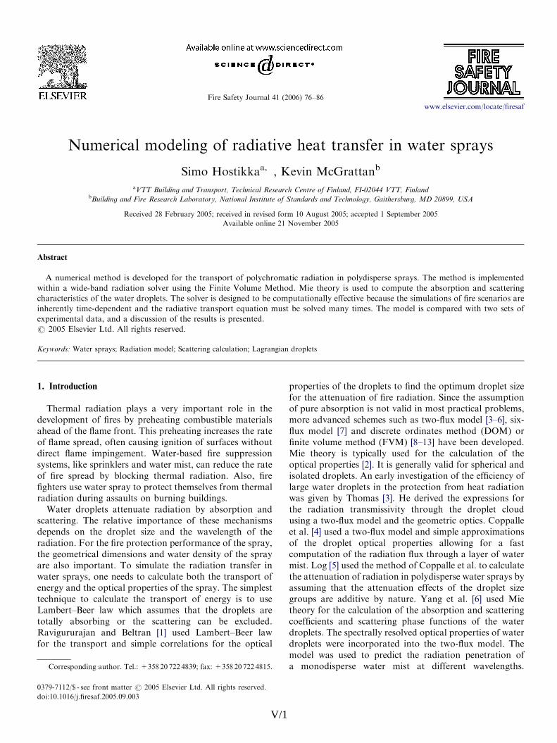
The measured and predicted attenuation results for althree nozzles and flow rates are compared in Fig. 5. Since agood general agreement was found for all three nozzlesand the results of the individual nozzles are well distinct inthe flow-rate vs. attenuation space, we can assume that themodel can properly take into account both the effect of thewater load and the effect of the droplet size distributionOnly the mid-range flow rates of nozzle B and the highesflow rates of nozzle D show sizable discrepancies. Thesediscrepancies are probably caused by a combination omeasurement errors and model inaccuracy. The drople
V/
size measurements, in particular, are difficult to conduct inlarge scale sprays. Some uncertainty is also related to thesimulation boundary conditions of the droplet size.
7
3
Datmab3mrAsu
ropantbnwtps3w
tdawr
wacTod
2bsdvcgdgaf
rdcsedhsmr
svTaswdtaf
ARTICLE IN PRESS
0 2 4 6 80
10
20
30
40
Flow rate (l/min)
Atte
nuat
ion
(%)
A
B
D
Fig. 5. Comparison of measured and predicted attenuation of thermal
radiation at spray nozzles A, B and D, and different flow rates. Lines
represent simulation results.
SOURCE
0.2 m
SPRAY
SPECTROMETER
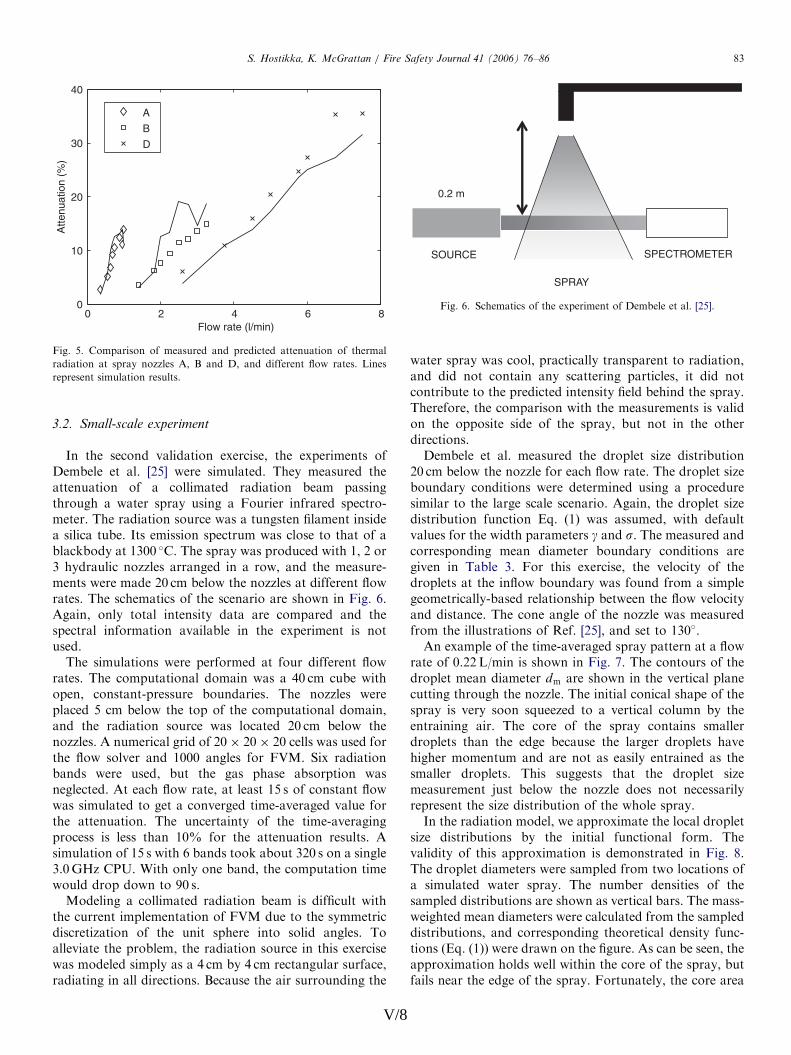
Fig. 6. Schematics of the experiment of Dembele et al. [25].
S. Hostikka, K. McGrattan / Fire Safety Journal 41 (2006) 76–86 83
.2. Small-scale experiment
In the second validation exercise, the experiments ofembele et al. [25] were simulated. They measured thettenuation of a collimated radiation beam passinghrough a water spray using a Fourier infrared spectro-eter. The radiation source was a tungsten filament insidesilica tube. Its emission spectrum was close to that of alackbody at 1300 C. The spray was produced with 1, 2 orhydraulic nozzles arranged in a row, and the measure-ents were made 20 cm below the nozzles at different flowates. The schematics of the scenario are shown in Fig. 6.gain, only total intensity data are compared and thepectral information available in the experiment is notsed.The simulations were performed at four different flow
ates. The computational domain was a 40 cm cube withpen, constant-pressure boundaries. The nozzles werelaced 5 cm below the top of the computational domain,nd the radiation source was located 20 cm below theozzles. A numerical grid of 20 20 20 cells was used forhe flow solver and 1000 angles for FVM. Six radiationands were used, but the gas phase absorption waseglected. At each flow rate, at least 15 s of constant flowas simulated to get a converged time-averaged value forhe attenuation. The uncertainty of the time-averagingrocess is less than 10% for the attenuation results. Aimulation of 15 s with 6 bands took about 320 s on a single.0GHz CPU. With only one band, the computation timeould drop down to 90 s.Modeling a collimated radiation beam is difficult with
he current implementation of FVM due to the symmetriciscretization of the unit sphere into solid angles. Tolleviate the problem, the radiation source in this exerciseas modeled simply as a 4 cm by 4 cm rectangular surface,adiating in all directions. Because the air surrounding the
V/8
ater spray was cool, practically transparent to radiation,nd did not contain any scattering particles, it did notontribute to the predicted intensity field behind the spray.herefore, the comparison with the measurements is validn the opposite side of the spray, but not in the otherirections.Dembele et al. measured the droplet size distribution0 cm below the nozzle for each flow rate. The droplet sizeoundary conditions were determined using a procedureimilar to the large scale scenario. Again, the droplet sizeistribution function Eq. (1) was assumed, with defaultalues for the width parameters g and s. The measured andorresponding mean diameter boundary conditions areiven in Table 3. For this exercise, the velocity of theroplets at the inflow boundary was found from a simpleeometrically-based relationship between the flow velocitynd distance. The cone angle of the nozzle was measuredrom the illustrations of Ref. [25], and set to 130.An example of the time-averaged spray pattern at a flow
ate of 0.22 L/min is shown in Fig. 7. The contours of theroplet mean diameter dm are shown in the vertical planeutting through the nozzle. The initial conical shape of thepray is very soon squeezed to a vertical column by thentraining air. The core of the spray contains smallerroplets than the edge because the larger droplets haveigher momentum and are not as easily entrained as themaller droplets. This suggests that the droplet sizeeasurement just below the nozzle does not necessarilyepresent the size distribution of the whole spray.In the radiation model, we approximate the local droplet
ize distributions by the initial functional form. Thealidity of this approximation is demonstrated in Fig. 8.he droplet diameters were sampled from two locations ofsimulated water spray. The number densities of the
ampled distributions are shown as vertical bars. The mass-eighted mean diameters were calculated from the sampledistributions, and corresponding theoretical density func-ions (Eq. (1)) were drawn on the figure. As can be seen, thepproximation holds well within the core of the spray, butails near the edge of the spray. Fortunately, the core area

.
f
.
.
lt
l.
ARTICLE IN PRESS
Table 3
Boundary conditions of the TG03 spray droplets
Flow rate dm (exp.) dm (BC) Velocity (BC)
(L/min/nozzle) (mm) (mm) (m/s)
0.14 187 264 0.33
0.22 135 187 0.51
0.28 115 155 0.65
0.33 104 140 0.75
-0.2 -0.1 0 0.1 0.20
0.05
0.1
0.15
0.2
0.25
0.3
0.35
0.4
x (m)
z (m
) 125
150
175
200
125
200 125
NOZZLE
dm (µ m)
Fig. 7. Contours of the time averaged droplet mean diameter field at
0.22L/min flow rate. The co-ordinates correspond to the computational
domain used.
0 100 200 300 400 5000
0.004
0.008
0.012
Diameter (µm)
Num
ber
dens
ity
SPRAY CORE dm = 163 µm
SPRAY EDGE dm = 261 µm
Fig. 8. Theoretical and sampled size distributions in the core and close to
the edge of the spray. Lines are the assumed probability density functions
and bars are the sample histograms from the simulation.
S. Hostikka, K. McGrattan / Fire Safety Journal 41 (2006) 76–8684
V/
is much more important for the radiation attenuationbecause the number density is higher there than at the edgeThe approximation may also fail if the spray penetrates ahot environment, because the evaporation rate depends onthe droplet radius, and probably affects the shape of thesize distribution.In this scenario, the independence of the spatial and
angular resolutions is very difficult to achieve. The effect othe spatial resolution was studied by reducing the cell sizefrom 2.0 cm to 1.0 cm. As a result, the attenuation in thecase of one nozzle at 0.14 L/min flow rate changed from8.3% to 11.4%, with 10.0% being the experimental valueUnfortunately, the 1 cm grid cells could not be used for theall cases due to the strong increase of computational costThe effect of angular resolution is studied in Fig. 9 byplotting the combined total intensity UðxÞ at the horizontaline passing through the center of the radiation source adifferent values of NO. Fig. 9(a) shows that UðxÞ
450 kW=m2 close to the source and UðxÞ 10 kW=m2 inthe spray region. For NOX1000, the absolute value seemswell converged but the change of the field from the initiastate in Fig. 9(b) shows no convergence even at NO ¼ 3000
-0.2 -0.1 0 0.1 0.2100
101
102
103
x (m)
U(x
) (k
W/m
2 )
NΩ
1003001000300010000
-0.2 -0.1 0 0.1 0.2-1
-0.8
-0.6
-0.4
-0.2
0
0.2
0.4
x (m)
U(x
)-U
0(x)
(kW
/m2 )
(a)
(b)
Fig. 9. The effect of the angular accuracy on (a) combined total intensity
U and (b) the change of U .
9
TacccasfiuiarsrdocciaN
titaspm
aadmapas8pio[ti
ci
4
wmaai
eptcdsuIilt
trtscc
A
VN
R
ARTICLE IN PRESS
Table 4
Results of the TG03 spray simulation
Flow rate Attenuation (%)
(L/min/nozzle) 1 nozzle 2 nozzles 3 nozzles
Measured Predicted Measured Predicted Measured Predicted
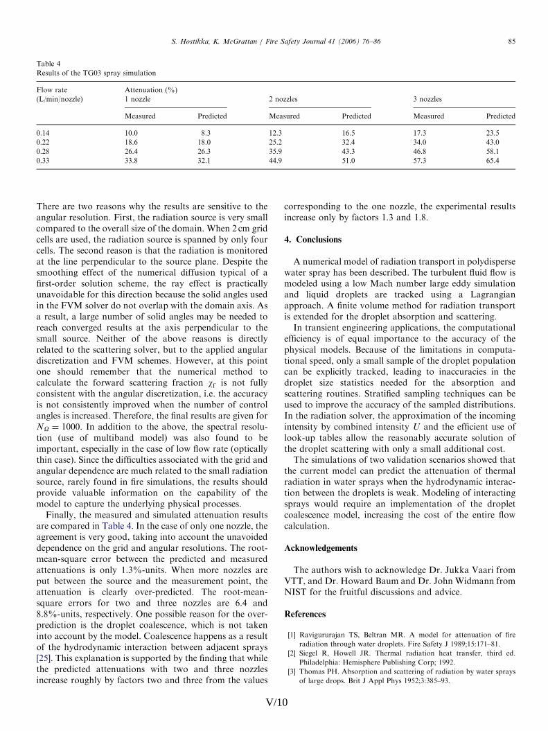
0.14 10.0 8.3 12.3 16.5 17.3 23.5
0.22 18.6 18.0 25.2 32.4 34.0 43.0
0.28 26.4 26.3 35.9 43.3 46.8 58.1
0.33 33.8 32.1 44.9 51.0 57.3 65.4
S. Hostikka, K. McGrattan / Fire Safety Journal 41 (2006) 76–86 85
here are two reasons why the results are sensitive to thengular resolution. First, the radiation source is very smallompared to the overall size of the domain. When 2 cm gridells are used, the radiation source is spanned by only fourells. The second reason is that the radiation is monitoredt the line perpendicular to the source plane. Despite themoothing effect of the numerical diffusion typical of arst-order solution scheme, the ray effect is practicallynavoidable for this direction because the solid angles usedn the FVM solver do not overlap with the domain axis. Asresult, a large number of solid angles may be needed toeach converged results at the axis perpendicular to themall source. Neither of the above reasons is directlyelated to the scattering solver, but to the applied angulariscretization and FVM schemes. However, at this pointne should remember that the numerical method toalculate the forward scattering fraction wf is not fullyonsistent with the angular discretization, i.e. the accuracys not consistently improved when the number of controlngles is increased. Therefore, the final results are given for
O ¼ 1000. In addition to the above, the spectral resolu-ion (use of multiband model) was also found to bemportant, especially in the case of low flow rate (opticallyhin case). Since the difficulties associated with the grid andngular dependence are much related to the small radiationource, rarely found in fire simulations, the results shouldrovide valuable information on the capability of theodel to capture the underlying physical processes.Finally, the measured and simulated attenuation results
re compared in Table 4. In the case of only one nozzle, thegreement is very good, taking into account the unavoidedependence on the grid and angular resolutions. The root-ean-square error between the predicted and measuredttenuations is only 1.3%-units. When more nozzles areut between the source and the measurement point, thettenuation is clearly over-predicted. The root-mean-quare errors for two and three nozzles are 6.4 and.8%-units, respectively. One possible reason for the over-rediction is the droplet coalescence, which is not takennto account by the model. Coalescence happens as a resultf the hydrodynamic interaction between adjacent sprays25]. This explanation is supported by the finding that whilehe predicted attenuations with two and three nozzlesncrease roughly by factors two and three from the values
V/10
orresponding to the one nozzle, the experimental resultsncrease only by factors 1.3 and 1.8.
. Conclusions
A numerical model of radiation transport in polydisperseater spray has been described. The turbulent fluid flow isodeled using a low Mach number large eddy simulationnd liquid droplets are tracked using a Lagrangianpproach. A finite volume method for radiation transports extended for the droplet absorption and scattering.In transient engineering applications, the computational
fficiency is of equal importance to the accuracy of thehysical models. Because of the limitations in computa-ional speed, only a small sample of the droplet populationan be explicitly tracked, leading to inaccuracies in theroplet size statistics needed for the absorption andcattering routines. Stratified sampling techniques can besed to improve the accuracy of the sampled distributions.n the radiation solver, the approximation of the incomingntensity by combined intensity U and the efficient use ofook-up tables allow the reasonably accurate solution ofhe droplet scattering with only a small additional cost.The simulations of two validation scenarios showed that
he current model can predict the attenuation of thermaladiation in water sprays when the hydrodynamic interac-ion between the droplets is weak. Modeling of interactingprays would require an implementation of the dropletoalescence model, increasing the cost of the entire flowalculation.
cknowledgements
The authors wish to acknowledge Dr. Jukka Vaari fromTT, and Dr. Howard Baum and Dr. John Widmann fromIST for the fruitful discussions and advice.
eferences
[1] Ravigururajan TS, Beltran MR. A model for attenuation of fire
radiation through water droplets. Fire Safety J 1989;15:171–81.
[2] Siegel R, Howell JR. Thermal radiation heat transfer, third ed.
Philadelphia: Hemisphere Publishing Corp; 1992.
[3] Thomas PH. Absorption and scattering of radiation by water sprays
of large drops. Brit J Appl Phys 1952;3:385–93.

.
,
f
.
.
e
:
.
f
e
t
t
r
t
l
.
,
t
-
l
-
/
t
e
-
l
:
e
e
l
r
r
r
ARTICLE IN PRESSS. Hostikka, K. McGrattan / Fire Safety Journal 41 (2006) 76–8686
[4] Coppalle A, Nedelka D, Bauer B. Fire protection: water curtains
Fire Safety J 1993;20:241–55.
[5] Log T. Radiant heat attenuation in fine water sprays. In: Interflam
96, Seventh international fire science and engineering conference
Interscience Communications; 1996, p. 425–34.
[6] Yang W, Parker T, Ladouceur HD, Kee RJ. The interaction o
thermal radiation and water mist in fire suppression. Fire Safety
J 2004;39:41–66.
[7] Keramida EP, Karayannis AN, Boudouvis AG, Markatos NC
Numerical modeling of radiant heat attenuation through water mist
Combust Sci Technol 2000;159:351–71.
[8] Berour N, Lacroix D, Boulet P, Jeandel G. Radiative and conductiv
heat transfer in a nongrey semitransparent medium. Application to
fire protection curtains. J Quant Spectrosc Radiat Transfer 2004;86
9–30.
[9] Jinbo H, Liming R, Heping T. Effect of anisontropic scattering on
radiative heat transfer in two-dimensional rectangular media
J Quantit Spectrosc Radiat Transfer 2003;78:151–61.
[10] Trivic DN, O’Brien TJ, Amon CH. Modeling the radiation o
anisotropically scattering media by coupling Mie theory with finit
volume method. Int J Heat Mass Transfer 2004;47:5765–80.
[11] Collin A, Boulet P, Lacroix D, Jeandel G. On radiative transfer in
water spray curtains using the discrete ordinates method. J Quanti
Spectrosc Radiat Transfer 2005;92:85–110.
[12] Consalvi JL, Porterie B, Loraud JC. On the use of gray assumption
for modeling thermal radiation through water sprays. Numer Hea
Transfer, Part A 2003;44:505–19.
[13] Liu LH, Ruan LM, Tan HP. On the discrete ordinates method fo
radiative heat transfer in anisotropically scattering media. Int J Hea
Mass Transfer 2002;45:3259–62.
[14] McGrattan KB, Baum HR, Rehm RG, Forney GP, Floyd JE, Prasad
K, Hostikka S. Fire dynamics simulator (Version 3), Technica
Reference Guide, Technical Report NISTIR 6783, 2002 edition
National Institute of Standards and Technology, Gaithersburg
Maryland, November 2002.
V/
[15] Are S, Hou S, Schmidt DP. Second-order spatial accuracy in
Lagrangian–Eulerian Spray Calculations. Numer Heat Transfer, Par
B 2005;48:25–44.
[16] Chan TS. Measurements of water density and droplet size distribu
tions of selected ESFR sprinklers. J Fire Prot Eng 1994;6(2):79–87.
[17] Hostikka S, McGrattan KB, Hamins A. Numerical modeling of poo
fires using LES and finite volume method for radiation, In: Fire safety
science—proceedings of the seventh international symposium. Inter
national Association for Fire Safety Science; 2003, p. 383–94.
[18] Wiscombe W. Mie scattering calculations: advances in technique and
fast, vector-speed computer codes, NCAR Technical Note NCAR
TN-140+STR, National Center For Atmospheric Research, 1979
(revised 1996).
[19] Hale GM, Querry MR. Optical constants of water in the 200 nm to
200mm wavelength region. Appl Opt 1973;12:555–63.
[20] Raithby GD, Chui EH. A finite-volume method for predicting
radiant heat transfer in enclosures with participating media. J Hea
Transfer 1990;112(2):415–23.
[21] Kim SH, Huh KY. Assessment of the finite-volume method and th
discrete ordinate method for radiative heat transfer in a three
dimensional rectangular enclosure. Numer Heat Transfer, Part B
1999;35:85–112.
[22] Murrel JV, Crowhurst D, Rock P. Experimental study of the therma
radiation attenuation of sprays from selected hydraulic nozzles. In
Proceedings of Halon options technical working conference. Th
University of New Mexico: Albuquerque; 1995. p. 369–78.
[23] You H. Investigation of spray patterns of selected sprinklers with th
FMRC drop size measuring system. In: Fire safety science—
proceedings of the first international symposium. Internationa
Association for Fire Safety Science; 1986. p. 1165–76.
[24] Widmann JF. Phase Doppler interferometry measurements in wate
sprays produced by residential fire sprinklers. Fire Safety
J 2001;36(6):545–67.
[25] Dembele S, Wen JX, Sacadura J-F. Experimental study of wate
sprays for the attenuation of fire thermal radiation. J Heat Transfe
2001;123:534–43.
11