numerical aspects of a pneumatic tyre model analysis · numerical aspects of a pneumatic tyre model...
TRANSCRIPT
TECHNICAL SCIENCESAbbrev.: Techn. Sc., No 12, Y 2009
DOI 10.2478/v10022-009-0016-5
NUMERICAL ASPECTS OF A PNEUMATICTYRE MODEL ANALYSIS
Józef PelcChair of Mechanics and Machine Design
University of Warmia and Mazury in Olsztyn
Key words: tyre, computational code, finite element method, block diagram, deformation, strength.
Abstract
This paper presents a method of axisymmetric analysis of a pneumatic tyre model, based on thefinite element method. A brief characterisation has been provided of a heterogeneous tyre model,which consists of three groups of materials: cord-rubber composite, physically nonlinear rubber andbead wire steel. The system is also geometrically nonlinear. This is all reflected in a detailed blockdiagram of the author’s in-house code intended for analysis of deformation and strength of pneumatictyres. The results of exemplary calculations made with the use of this code are presented.
NUMERYCZNE ASPEKTY ANALIZY MODELU OPONY PNEUMATYCZNEJ
Józef Pelc
Katedra Mechaniki i Podstaw Konstrukcji MaszynUniwersytet Warmińsko-Mazurski w Olsztynie
Słowa kluczowe: opona, program obliczeniowy, metoda elementów skończonych, schemat blokowy,deformacja, wytrzymałość.
Abstrakt
W pracy przedstawiono sposób analizy obrotowo-symetrycznego modelu opony pneumatycznejbazującego na metodzie elementów skończonych. Podano krótką charakterystykę modelu niejed-norodnej opony, w której wyróżniono trzy grupy materiałów: kompozyt kord-guma, fizykalnienieliniową gumę i stal drutówek. Układ charakteryzuje się również nieliniowością geometryczną.Wszystko to ma swoje odbicie w szczegółowo przedstawionym schemacie blokowym programuautorskiego przeznaczonego do analizy deformacji i wytrzymałości opon pneumatycznych. Zamie-szczono wyniki przykładowych obliczeń wykonanych za pomocą tego programu.
Introduction
Currently, the production of new commercial models of pneumatic tyres doesnot start until its geometric parameters and dimensions have been tested, thetyre has been mounted onto a rim and inflated, its strength, shape anddistribution of pressure in the area of static contact with the ground have beenexamined and even the behaviour of the tyre under operation conditions hasbeen checked. A future product is therefore tested and improved at the designphase, which requires a reliable computer model. Due to a considerable progressin computer methods in solid mechanics and power of computers, a number ofcommercial FEM codes are currently available which provide extensive analyticcapabilities for even the most complex problems of the mechanics of a deform-able body. Hence, a problem arises as to whether an analysis of deformation andstrength of a pneumatic tyre can be performed directly with an FEM code, evenif it is one of the most advanced software code. It is possible with one tyre;however, this is unacceptable to tyre designers due to the time needed to preparea computational model. The fundamental difficulty lies in the fact that due tothe technology of tyre formation, the density and angle of cords depend on thedistance of a finite element from a tyre axis of rotation. For example, the corddensity in the ply of a truck tyre decreases by ca. 50% between the tyre bead tothe apex (PELC 1995c). Therefore, when preparing data which describe themechanical properties of a tyre material, one should specify them separately foreach finite element. This is why the author has spent years developing a tyrecomputational model based on the finite element method (PELC 1992, 1995a,2000, 2002), followed by algorithms and a computer code intended for analysis ofpneumatic tyre deformation analysis, in which data are generated from theproperties of a raw layer of cord-rubber composite (wound on a tyre buildingdrum) and the position of an element in a formed tyre. Moreover, a tyre ischaracterised by complex geometry and heterogeneity.
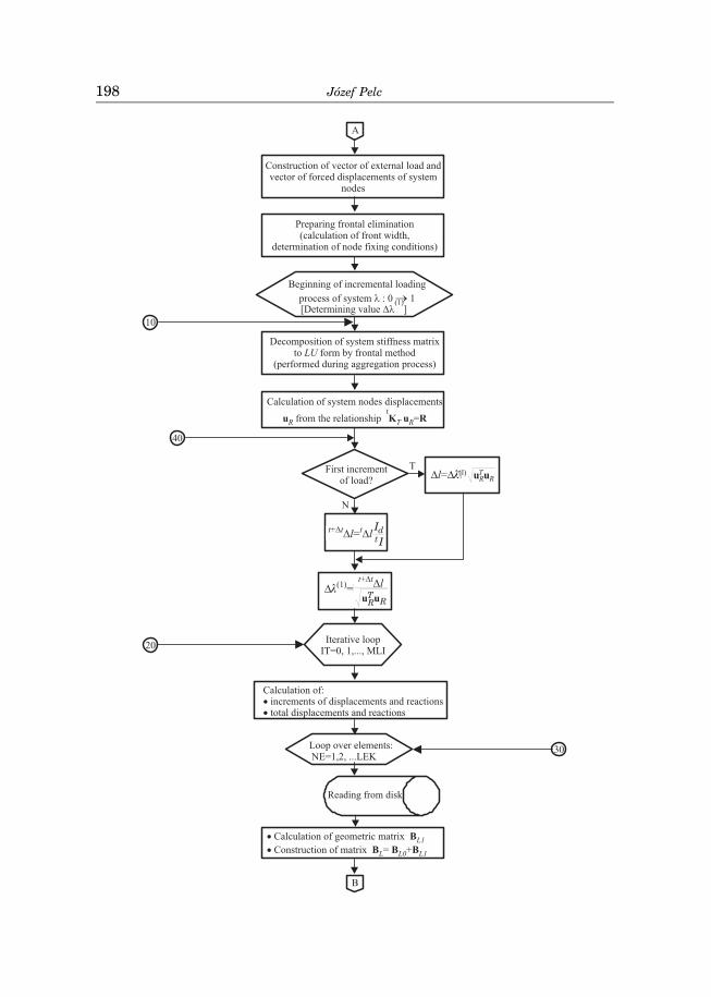
Loads acting on a tyre may cause considerable displacements and somematerials, such as rubber, behave as nonlinear-elastic elements. Therefore,a tyre model is a nonlinear model and determination of an equilibrium path forsuch a system requires an incremental-iterative technique. All these issues arereflected in a block diagram of the author’s code, intended for pneumatic tyremodel axisymmetric analysis.
Characterisation of an axisymmetric tyre model
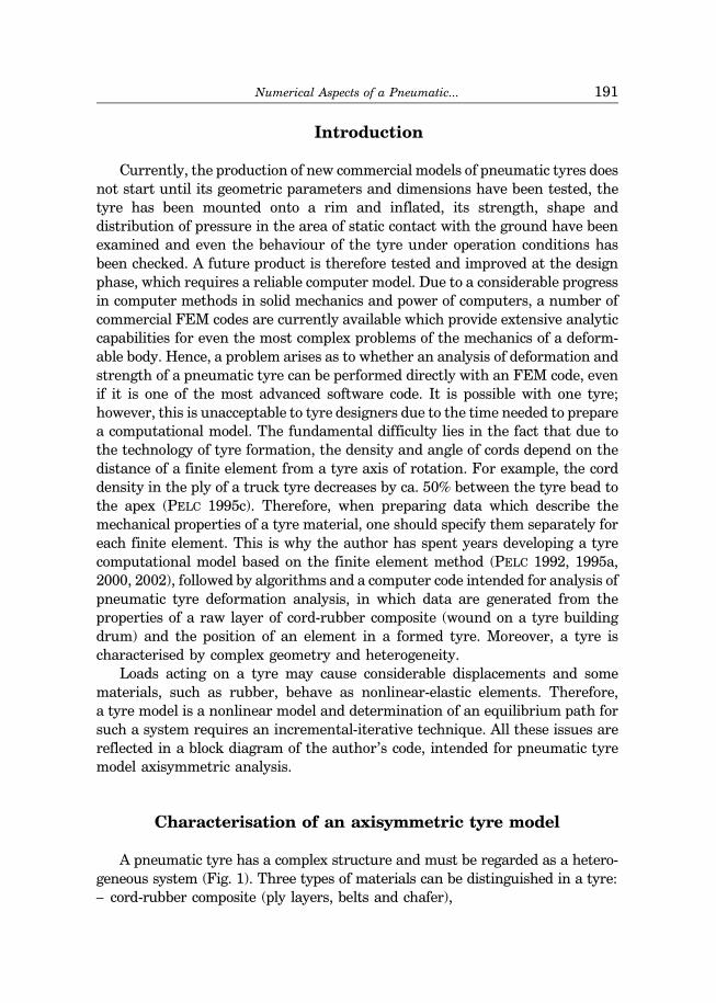
A pneumatic tyre has a complex structure and must be regarded as a hetero-geneous system (Fig. 1). Three types of materials can be distinguished in a tyre:– cord-rubber composite (ply layers, belts and chafer),
Numerical Aspects of a Pneumatic... 191
– rubber (e.g. tread, sidewall, etc.),– steel (bead wire).
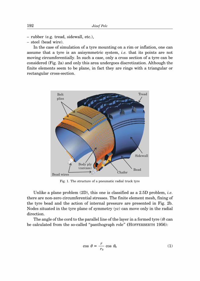
In the case of simulation of a tyre mounting on a rim or inflation, one canassume that a tyre is an axisymmetric system, i.e. that its points are notmoving circumferentially. In such a case, only a cross section of a tyre can beconsidered (Fig. 2a) and only this area undergoes discretization. Although thefinite elements seem to be plane, in fact they are rings with a triangular orrectangular cross-section.
Bead wires
Body ply
Belt
plies
Sidewall
Tread
BeadChafer
(carcass)
Fig. 1. The structure of a pneumatic radial truck tyre
Unlike a plane problem (2D), this one is classified as a 2.5D problem, i.e.there are non-zero circumferential stresses. The finite element mesh, fixing ofthe tyre bead and the action of internal pressure are presented in Fig. 2b.Nodes situated in the tyre plane of symmetry (yz) can move only in the radialdirection.
The angle of the cord to the parallel line of the layer in a formed tyre (θ) canbe calculated from the so-called “panthograph role” (HOFFERBERTH 1956):
cos θ =r
cos θ0 (1)r0
Józef Pelc192
where:r0/r – the radius of a point of a layer on a drum/in a tyre,θ0 – angle of a cord in a green layer.
y
x
Rim
za b
Fig. 2. An axisymmetric model of a truck tyre: a – cross section with layers, b – mesh of finite elementsand boundary conditions
The cord density in a tyre layer depends on the density in a green layerplaceed on a drum ep0:
ep = ep0
r0 sin θ0 (2)r sin θ
and it allow to determine the ply cord volume fraction based on the crosssection area of a cord (Ac) and the layer thickness (t):
vc =epAc (3)
t
Numerical Aspects of a Pneumatic... 193
The fraction value provides the basis for calculation of effective materialconstants for a cord-rubber composite layer. Assuming that the shear modulusfor cords is greater than it is for rubber, HALPIN and TSAI (1969) formulayields:
E1 = Ecvc + Er (1 – vc)
E2=Er(1 + 2vc)
1 – vc(4)
ν12 = νcvc + νr(1 – vc)
G12 = Gr1 + vc
1 – vc
where:letters E/G/ν – denote Young and Kirchhoff moduli and Poisson ratio, respect-ively, and the c/r indices denote cord and rubber, respectively. Axis 1 is parallelto cord, while axis 2 denotes one that is perpendicular to it, lying on the layerplane.
In a displacement formulation of FEM, assumed in the axisymmetric tyremodel, it is convenient to describe rubber properties as if it was a nearlyincompressible material, as proposed by BLATZ and KO (1962).
Having determined the tangent constitutive tensor for the material (0D),one can calculate the second Piola-Kirchhoff stress tensor (0S) based on theknown increment of Green-Lagrange strain tensor (0E):
0S = 0D0E (5)
Defining the tensor as (BROCKMAN 1986)
t0H =
∂ I3 (6)∂ t
0Cwhere:tC denotes Cauchy-Green deformation tensor, and I3 – its third invariant, andtaking into account the strain energy density function in the Blatz-Ko modelfor a nearly incompressible material, the second Piola-Kirchhoff stress tensorcan be written:
t0S =
∂ W= µ [I – I3
–0.5(a+2) t0H] (7)
∂ t0E
Józef Pelc194
For a rubber-type elastomer, regarded as a hyperelastic material,
0D =∂ 2W
=d t
0S (8)∂ t
0E ∂ t0E d t
0E
Additionally introducing a tensor of the fourth order
t0Q =
∂ t0H (9)
∂ t0C
yields a tensor of incremental constitutive relationship (tangent)
0D = µ (a + 2)I3—0.5(a+4) t
0H t0H – 2 µ I3
–0.5(a+2) t0Q (10)
Material constants µ and a are determined from the results of experimentsperformed for each type of rubber. In axisymmetric problems – t
0C31 = t0C32
= 0 and t0C33 = 1.
Material constants matrix (constitutive matrix) is constructed in accord-ance with the principles of composite material mechanics (JONES 1975).
Node displacements in the finite element axisymmetric tyre model aredetermined by the incremental method with iterations, based on a matrixequation (BATHE 1982):
(t0KL + t
0KNL) u(i) = t+∆tR – t+∆t0F(i–1) (11)
where:u(i) = t+∆tu(i) – t+∆tu(i–1), t+∆tu(0) = tu, t+∆t
0F(0) = t0F, whereas t+∆tR represents
a vector of nodal external forces which act on a tyre. The index in bracketsdenotes the number of iteration.
A linear stiffness matrix t0KL, non-linear stiffness matrix t
0KNL and a vectorof internal forces t
0F are calculated from a matrix (linear – t0BL and non-linear
– t0BNL) which occurs in strain-displacement relations, incremental constitutive
matrix 0D as well as matrix t0S and vector t
0S, made up of the components of thesecond Piola-Kirchhoff stress tensor. It must be stressed that matrix t
0BL is thesum of two components: t
0BL0 with constant terms and t0BL1 with the terms
dependent on the level of displacements, i.e. which change during the in-cremental-iterative process.
Numerical Aspects of a Pneumatic... 195
Block diagram of the author’s code
The code intended for analysis of axisymmetric models of pneumatic tyres hasbeen developed by the author over many years. Due to the complicatedstructure of pneumatic tyres, the code is considerably large, with ca. 4000 linesin the FORTRAN language (excluding comment lines). An input data file forthe author’s code is generated with preprocessing tools, described by PELC(1995b). The data are grouped in sections with specific names (numbers ofelements and nodes, node coordinates, types of elements, materials assigned toelements, boundary and load conditions) and have a structure typical for FEMcodes, except a significant difference in description of the model materialparameters. The data constitute a section in an input data file and contain:name of the material, thickness of the layer (t), cord cross section area (Ac),density of cord in a layer on the drum (ep0), angle of cord to the parallel line ofthe tyre building drum (θ0), the layer radius on the drum (r0), the Youngmodulus of the cord (Ec), Poisson ratio for the layer rubber or the a parameterfor the Blatz-Ko rubber model (νr, a), shear modulus for the layer rubber orparameter µ for the Blatz-Ko rubber model (Gr, µ). (cf. PELC 2007). Unlikecommercial FEM codes, data for the author’s code do not contain the values ofcord-rubber layer effective constants because for a specific tyre composite theydepend on the distance of a layer point from the tyre axis of rotation. Thevalues of those constants are calculated in the relevant subroutine for consecu-tive elements and material parameter matrices are constructed.
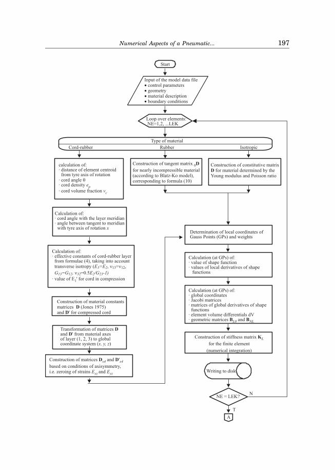
Due to the three selected types of materials in tyre, the code block diagram(Fig. 3) is divided into three paths, with that related to the cord-rubbercomposite being the most complex. A bimodular characteristic of the cord wasassumed with a high value of the Young modulus for stretching and anextremely small value for compression. Therefore, two matrices of materialconstants are prepared and which of them will be used depends on the state ofthe current stress in cord, observed during the tyre incremental loading. Dueto the assumed rotational symmetry of the problem (i.e. zeroing of deforma-tions Exz and Eyz), 4×4 matrices are obtained from full constitutive matricesD and D’.
An non-inflated tyre has a very low stiffness. Therefore, load incrementsduring the initial phase of simulation must be very small for the iterationprocess to be convergent. With increasing internal pressure, the systembecomes increasingly stiff and load increments may be increased. The author’scomputation code employs the arc-length control method as presented byCRISFIELD (1981), which makes it possible to automatically match the length ofthe load step with the degree of non-linearity of the equilibrium path and helpspass through so-called “limit points” (BADUR 1979). The load level in the
Józef Pelc196
A
Numerical Aspects of a Pneumatic... 197
B
A
10
RTRl uu
)1(����
I
Ill
tdttt �����
RTR
tt l
uu
�����
)1(�
30
40
Józef Pelc198
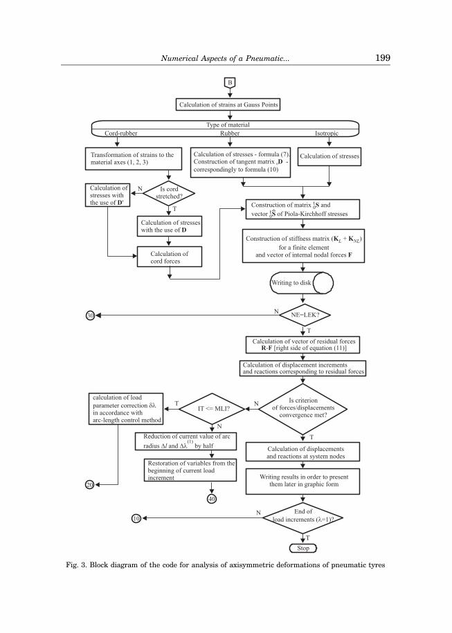
Fig. 3. Block diagram of the code for analysis of axisymmetric deformations of pneumatic tyres
Numerical Aspects of a Pneumatic... 199
method is controlled by a dimensionless parameter λ, which is equal to zero atthe beginning of the incremental process and equal to one at its end. At thebeginning of the first load increment, the value of load increment ∆λ(1) is setarbitrarily. The radius of arc ∆l, which leads to the path of equilibrium, iscalculated with the use of displacement vector of all the nodes of the system(uR) and the information on the number of iterations performed in theprevious increment tI, whereas I denotes the desired number of iterations.Matrix tKT denotes the tangent matrix of the system. It is possible in thesubprogram which performs the iteration process to apply two criteria of theprocess convergence. One of them is based on the Euclidean norm of the nodalresidual force vector and the other is related to the iterative displacementincrement.
Illustrative calculation results
The author’s code can be used to analyse a tyre under axisymmetric loading(internal pressure, centrifugal force of inertia). It is also possible to apply anaxisymmetric displacements of a tyre bead nodes. The necessity for axialdisplacement of the bead nodes towards the tyre’s plane of symmetry (y,z)results from a greater spacing of beads in the vulcanisation form than after thetyre has been mounted on a rim. Radial displacements stem from the necessityof the tyre clamping on the rim during the mounting process in order to createthe proper friction necessary to transfer the moment of force from the driveand braking and to ensure air-tightness in the contact area between the beadand rim.
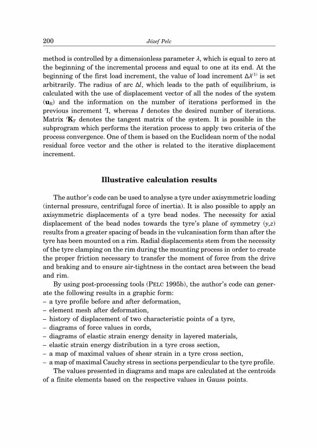
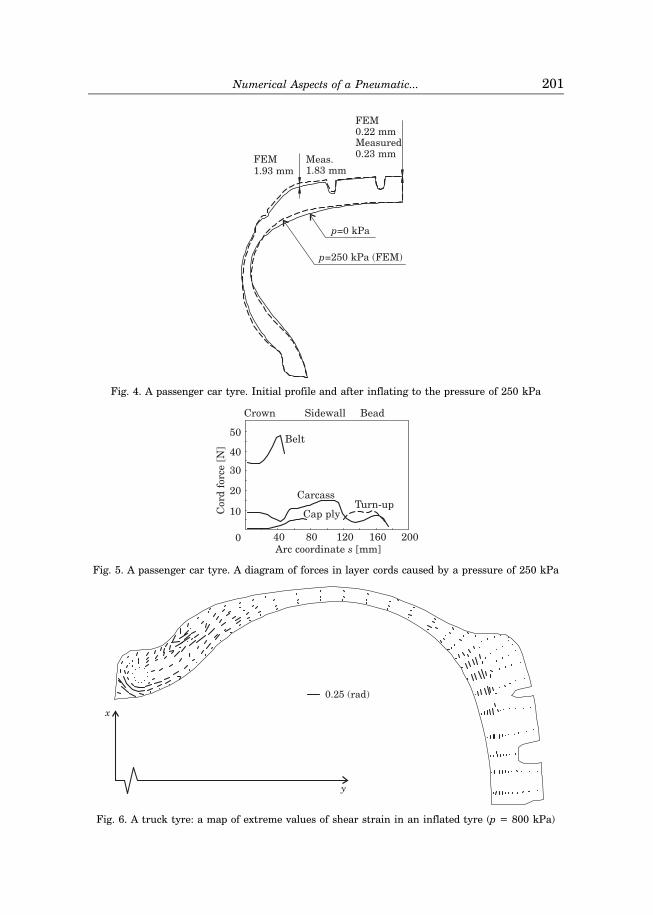
By using post-processing tools (PELC 1995b), the author’s code can gener-ate the following results in a graphic form:– a tyre profile before and after deformation,– element mesh after deformation,– history of displacement of two characteristic points of a tyre,– diagrams of force values in cords,– diagrams of elastic strain energy density in layered materials,– elastic strain energy distribution in a tyre cross section,– a map of maximal values of shear strain in a tyre cross section,– a map of maximal Cauchy stress in sections perpendicular to the tyre profile.
The values presented in diagrams and maps are calculated at the centroidsof a finite elements based on the respective values in Gauss points.
Józef Pelc200
1.93 mmFEM
1.83 mmMeas.
p=250 kPa (FEM)
p=0 kPa
0.23 mm
0.22 mmFEM
Measured
Fig. 4. A passenger car tyre. Initial profile and after inflating to the pressure of 250 kPa
Crown
Arc coordinate [mm]s
BeadSidewall
Turn-upCap ply
Belt
Carcass
80 120 160400
10
20
30
40
50
200
Cord
forc
e[N
]
Fig. 5. A passenger car tyre. A diagram of forces in layer cords caused by a pressure of 250 kPa
0.25 (rad)
y
x
Fig. 6. A truck tyre: a map of extreme values of shear strain in an inflated tyre (p = 800 kPa)
Numerical Aspects of a Pneumatic... 201

1.0 2.0 3.0 4.0
1.0
0
load
para
metr
�
measurement
p
vA
uB
v , uA B (mm)
model
AABB
Fig. 7. A truck tyre. A diagram of displacements of characteristic points of a tyre as a function ofinternal pressure
Summary and conclusions
Pneumatic tyre deformation modelling and strength analysis is a complexissue due to the heterogeneity and non-linear nature of the system. In thiscase, the method of finite elements seems to be the only tool for reliablemodelling of the behaviour of such a system. Due to the heterogeneousstructure of a tyre, the block diagram of a code for an axisymmetric tyre modelanalysis has a complex structure resulting from the distinguishing of threetypes of materials: cord-rubber composite, nearly incompressible rubber andsteel. The geometric non-linearity of a tyre and physical non-linearity ofrubber requires that the stiffness matrix of the system should be updatedduring the process of loading; the incremental-iterative procedure, visible inthe block diagram, is linked with it. The author’s computer code enablesanalysis of both passenger tyres and truck tyres.
Accepted for print 25.09.2009
References
BADUR J. 1979. Efektywne wyznaczanie punktów granicznych w nieliniowej mechanice konstrukcji.IV Konf. Metody Komputerowe w Mechanice Konstrukcji, tom II. Koszalin, kwiecień, s. 203–209.
BATHE K.J. 1982. Finite element procedures in engineering analysis. Prentice-Hall, Englewood Cliffs,N.Y.
HALPIN J.C., TSAI S.W. 1969. Effects of environmental factors on composite materials. AFML-TR,pp. 67–423.
Józef Pelc202
HOFFERBERTH W. 1956. Zur Festigkeit des Luftreifens. Kautschuk u. Gummi. 9: 225–231.JONES R.M. 1975. Mechanics of composite materials. McGraw-Hill LondonPELC J. 1992. Large displacements in tire inflation problem. Engineering Transactions, 40(1):
103–113.PELC J. 1995a. Pomiary i analiza metodą elementów skończonych opony całostalowej do samochodów
ciężarowych podczas pompowania. Acta Acad. Agricult. Tech. Olst. Aedificatio et Mechanica, 26:15–27.
PELC J. 1995b Pre-Processing and Post-Processing in Pneumatic Tire Analysis by the Finite ElementMethod. Acta Acad. Agricult. Tech. Olst. Aedificatio et Mechanica, 26: 29–36.
PELC J. 1995c. Orthotropic material model in pneumatic tire analysis. Proceedings of the XII PolishConference on Computer Methods in Mechanics, Warsaw–Zegrze, Poland, 9–13 May 1995,pp. 271–272.
PELC J. 2000. Material Modelling in Cord-Rubber Structures. Kautsch., Gummi Kunstst. 53(10):561–565.
PELC J. 2002. Static three-dimensional modelling of pneumatic tyres using the technique of elementoverlaying. Proc. Instn Mech. Engrs, Part D: J. Automobile Engineering, 216(9): 709–716.
PELC J. 2007. Modelowanie skończonych deformacji opon pneumatycznych, Rozprawy i Monografie 134,Wyd. UWM.
Numerical Aspects of a Pneumatic... 203