nuclear light bulb - nasa · pdf filethe engine power is around 4,600 megawatts, ... - closed...
TRANSCRIPT

N92- 1:. 110
NUCLEAR LIGHT BULB
Tom Latham
United Technologies Research Center
The nuclear light bulb engine is a closed cycle gas core concept. United Technologies
made a policy decision in the early days of gas core reactor development that we were
not to work on any concept that didn't have the potential of complete containment of thenuclear fuel.
During that era we did support NASA-Lewis with contracted open cycle gas core flow
test work and shared a great deal of technical information from the nuclear light bulb
program.
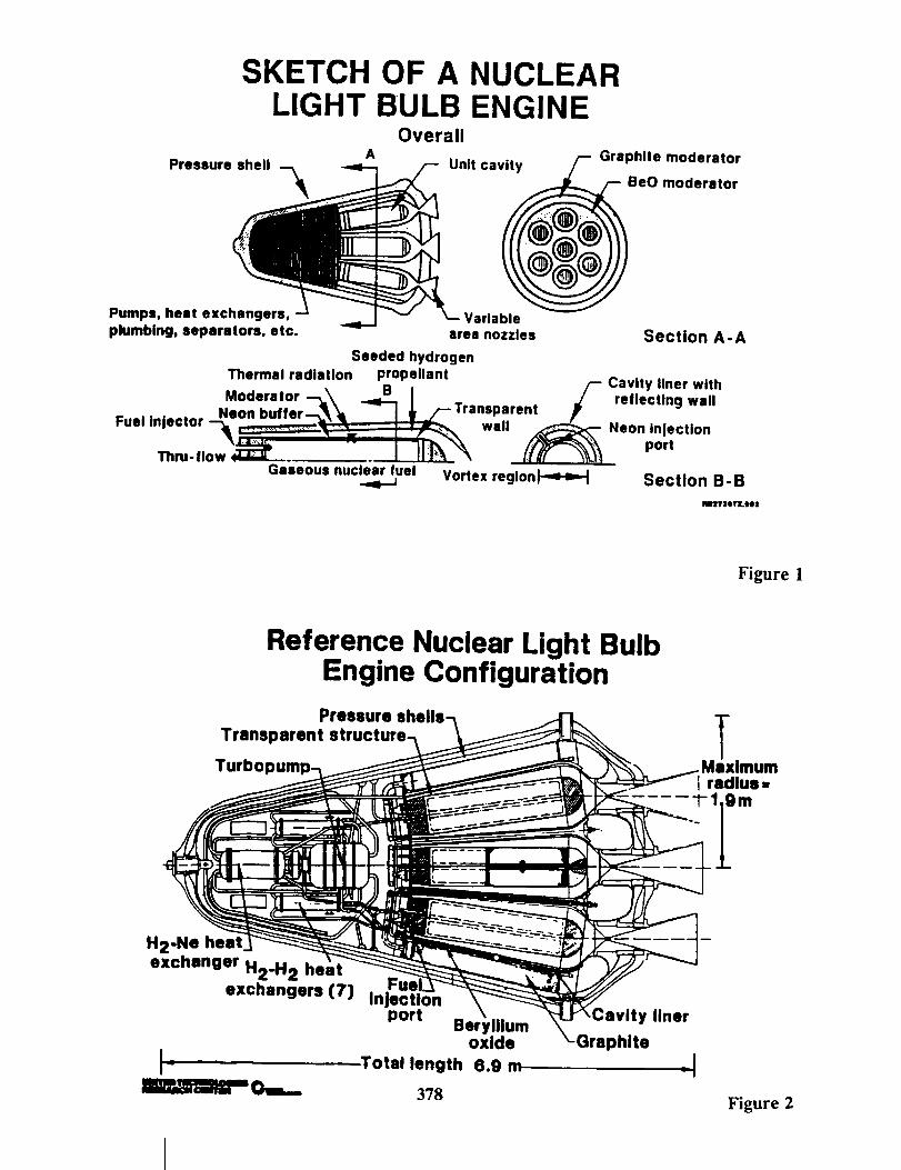
The nuclear light bulb concept provides containment by keeping the nuclear fuel fluid
mechanically suspended in a cylindrical geometry. Thermal heat passes through an
internally cooled, fused-silica, transparent wall and heats hydrogen propellant (Figure 1).
The seeded hydrogen propellant absorbs radiant energy and is expanded through a
nozzle.
Internal moderation was used in the configuration which resulted in a reduced critical
density requirement. This result was supported by criticality experiments. If, in addition,
we used U233 nuclear fuel instead of U235, we gained about a two-thirds reduction in
overall fuel loading.
A reference engine was designed that had seven cells and was sized to fit in what was
then predicted to be the shuttle bay mass and volume limitations (Figure 2).
The pressure vessel, the hydrogen cooling pumps, the secondary cooling system, fuel
handling systems and thrust nozzles fit into a bay that measures about seven meters long
by four meters in diameter. The total engine weight is around 70,000 pounds (Figure 3),
the engine power is around 4,600 megawatts, and the thrust-to-weight ratio is 1.3.
These numbers were chosen relatively carefully. We chose these operating levels so that
we did not have to use space radiators in the system to remove excess heat from the
moderator or pressure vessel. If you go much beyond this performance, you do have to
start using space radiators to remove extra heat.
If you increase specific impulse to 2,500 to 3,000 seconds, you have thermal radiation
dominated heating of the nozzle throat. There were studies done of nozzle throat
cooling schemes to remove the radiant heat. That's an important technical question to
tackle.
A VOICE: Radiation from the gas?
373PRECEDING P,_GE BLANK NOT FILMED
https://ntrs.nasa.gov/search.jsp?R=19920001892 2018-05-06T17:18:03+00:00Z

MR. LATHAM: Yes. The gas and the seed that is in it. The hydrogen flow through
the nozzle is optically thick because it has tiny tungsten seed particles in it.
Elements of the nuclear light bulb program included closed loop critical assembly tests
done at Los Alamos with UF 6 confined by argon buffer gas (Figure 4).
We also showed that transparent fused-silica, when subjected to a high intensity ionizing
dose rates, exhibit a radiation damage annealing effect that restores transparency.
We did some work that showed that the fuel region could be seeded with constituents
that would block UV radiation from the uranium plasma. That reduces radiation energy
absorption in the fused-silica wall at wavelengths below the UV cutoff. That has to be
verified experimentally.
Argon seeded with sub-micron tungsten particles to simulate seeded propellant was
heated by thermal radiation from a high power dc-arc. The radiant energy passed
through a fused silica wall to a propellant channel. A peak outlet temperature of 4500K
was reached, which is equivalent to a specific impulse or 1,350 seconds for hydrogen.
It was shown by a combination of calculations and experiments that internal moderation
produced a critical mass reduction (Figure 5).
In a 1.2 megawatt RF facility at the United Technologies Research Center, we used
uranium hexafluoride and tungsten hexafluoride as the simulated fuel. We seeded the
argon buffer gas with some fluorine gas to react with any fluorides that approached the
containment walls. In final experiments, we were getting only milligrams of deposits intests that ran about 40 minutes. The uranium fluorides are fuel forms that need to be
considered for these applications, at least as initial fuel concepts.
A level 3 technology readiness for this concept is estimated.
What are the effects of new technologies (Figure 6)? Certainly modern computational
fluid dynamics are going to tell us a lot more. We need to look at nozzle cooling designs
and what the upper limit is on specific impulse. There are a whole host of materials that
need to be readdressed: coatings, transparent materials, and composites, for example.
Space radiator redesign should reduce some weight; we need to look at the reference
engine generally with 1990's technology in mind. Mission architectures have changed
and we have to work with new regulations with regard to testing, crew safety, and space
operations.
Key technical issues include reactor and system stability (Figure 7). We didn't examine
failure modes and safety, and we don't have estimates of operating lifetime. Fuel and
buffer gas separation, handling and recirculation are areas that also must be addressed.
374

We don't know much about overall system reliability either. Correlation of fission versus
electrically heated tests has to be addressed and verified. We also need to do
experiments that validate that you can seed an optically thick plasma and control the
spectral distribution of emitted thermal radiation.
We did some missions analysis for a Mars mission back in 1971. The characteristics of
the systems used, which of course should be updated, are show in Figure 8. Theassumed transit times were 140 days out and 245 days back, with an 80 day stopover
(Figure 9).
The mission required four impulses; one impulse to get there, one to stop at Mars, one
impulse to leave and one impulse to return to Earth. The reference engine required an
initial mass in Earth orbit that was between a third and a quarter that of the solid core
nuclear rocket (Figure 10).
The numbers in parentheses are the number of engines needed to leave Earth, number
of engines needed at Mars, number of engines needed to leave Mars and, finally, the
number to return. No notation means you can do it all with one engine.
For the next steps (Figure 11 and 12), more fluid dynamic analysis and nozzle cooling
design work is needed. We should look at materials such as composites, coatings,
transparent wall materials, and evaluate the NASP database to see what kind of
materials are of use. We should redesign the reference engine using 1990's technology.
Modern mission analysis should be done, as well as environmental assessments of the
effects on crews by space and test operations. Then, we should define how to proceed.
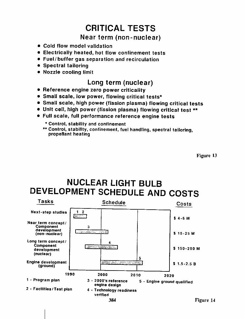
What are the critical tests (Figure 13)? Cold flow and more electrically heated tests are
needed to develop fuel recirculation and handling systems and also for demonstrations offluid mechanical confinement. Using the same kinds of tests, we should investigate fuel
and buffer gas circulation and reprocessing and measure the effects of spectral tailoring.
In the long term, nuclear criticality tests must be continued. Small scale low power tests
and small scale high power tests can be done using the solid core facilities for fuel
element tests. You can do a lot of proof-of-concept validation before you have to get to
full scale testing.
The key point here is that you can piggyback nuclear light bulb experiments using solid
core test reactors and facilities for small scale in-reactor proof-of-concept tests, thereby
saving money.
Here is a cut at costs and schedule (Figure 14).
In closing, it's hard to review all the work that was done. But a lot of technology was
considered some 10 to 20 years ago and in all cases, the feasibility of the nuclear light
375

bulb concept continued to be demonstrable.
376

BIBLIOGRAPHY
Tom Lathan
Nu¢l_ Li_zlat Bulb
1. Mcl.afferty, G.H.: Investigation of Gaseous Nuclear Rocket Technology - Summary Technical
Report. United Aircraft Research Laboratories Report H-910093-46, prepared under ContractNASw-847, November 1969.
. McLafferty, G.H.: Gas-Core Nuclear Rocket Engine Technology Status. Journal of Space.craaft and
Rockets, Vol. 7, No. 12, December 1970, p. 1391.
. Kendall, J.S.: Investigations of Gaseous Nuclear Rocket Technology -- Summary technical Report.
United Aircraft Research Laboratories Report L-910905-13, prepared under Contract SNPC-70,
September 1972.
4. Kendall, J.S. and T.S. Latham: Summary of Fluid Mechanics and Engine Charateristics Research on
the Nuclear Light Bulb Engine Concept. AIAA Paper No. 70-689, presented at AIAA 6th
Propulsion Joint Speicalist Conference, San Diego, CA June 1970.
° Latham, T.S.: Summary of Performance Charateristics of the Nuclear Light Bulb Engine. AIAA
Paper No. 71-642, presented at the Seventh IAA Propulsion Joint Speicalist Conference, Salt Lake
City, Utah, June 1971.
. Clement, J.D. and J.R. W'dliams: Gas Core Reactor Technology. Reactor Technology, Vol. 13, No.
3, Summer 1970, pp. 226-251.
. Latham, T.S. and RJ. Rodgers: Analytical Design and Performance Studies of Nuclear Furnace
Tests of Small Nuclear Light Bulb Models. United Aircraft Research Laboratories Report L-
910900-17, prepared under Contract SNPC-70, September 1972.
° Roman, W.C.: Argon/UF6 Plasma Experiments: UF6 Regeneration and Product Analysis. NASA
CR 3258. Prepared under NASA Contract NAS1-14329, March 1980.
. Latham, T.S. and R.J. Rodgers: Small Nuclear Light Bulb Engines with Cold Beryllium Reflectors.
AIAA Paper No. 72-1093, presented at AIAA\SAE 8th Joint Propulsion Specialist Conference, NewOrleans, LA, November 1972.
10. Jaminet, J.E. and J.S. Kendall: Vortex-Confined Uranium Hexafluoride Cavity Reactor Experiment.
United Technologies Research Center Report R80-914499-4 prepared under Contract X69-5627F-1,
April 1980.
377
SKETCH OF A NUCLEARLIGHT BULB ENGINE
Pumps, heat exchangers,
plumbing, separators, etc.
Overall
A Unit cavity Graphite moderator
eO moderator
Variablearea nozzles Section A-A
Seeded hydrogen
Thermal radiation propellant Cavity liner with
! /- r.,,.c,,o,w.,,• . . Neon buffer--_ _t ./-- Transparent
Fuel mleclor _'_',,--_" ............... _" ....."..:. ' ; " 7 _--_'_, wall _ Neon Injection
Th..-.ow_ I II_'_ (f_'_ portGaseous nuclear fuel Vortex regionl---=H=._ Section B-B
NatTIIIlr:LIO2
Figure 1
Reference Nuclear Light BulbEngine Configuration
Pressure
Transparent
Turbo dmum]radius-
H2-Ne heat
exchanger H2.H 2 heat
exchangers (7)
_ .
i-liP._mlml- o._
FuelInjection
port
Total length
378
'Iliumoxide
6.9 m
Cavity liner
Graphite.!
Figure 2

PERFORMANCE CHARACTERISTICS OFREFERENCE NUCLEAR LIGHT
BULB ENGINE
Engine weight
Engine power
Total propellant flow
Specific impulse
Thrust
Engine thrust- to-weight ratio
70,000 Ib
4600 MW
49.3 Ib / sec
1870 sec
92,000 Ib
1.3
Figure 3
GAS CORE NUCLEAR REACTOR
Program Achievements
• Flow Containment Demonstrated
- Cold Flow
- RF Plasma
- Closed Loop Critical Cavity Assembly
• Energy Coupling Demonstrated
- RF Plasma
- Radiation Annealing Effect
- Buffer Gas Tailoring
- Seeded Propellant Heating Test
• Equivalent Isp Approx 1350 sec.
379 Figure 4

GAS CORE NUCLEAR REACTOR
Program Achievements (Cont.)
• Internal Moderator Benefit Confirmed
- Almost 3:1 Reduction in Critical Mass
• Flow Rate Control Demonstrated
- Closed Loop Argon-UF6 Vortex Flow Syst.
• Los Alamos Critical Cavity Assembly
• Seven Tests
• Achieved 20 KW for Approx. 100 sec.
• No Unexpected Fluctuations
• Technology Readiness Level = 3
Figure 5
IMPACT OF NEW
TECHNOLOGIES / SAFETY REGULATIONS
• Computational fluid dynamics
• Cooled nozzle design
• Materials
• Space radiator design
• Reference engine with 1990's technology
• Mission architectures
• Environmental and crew safety
38O Figure 6

KEY TECHNICAL QUESTIONS
• Reactor/system stability over all operatingconditions
• Failure modes and safety impacts
• Operating lifetime/performance envelope
• Fuel/buffer gas separation/recirculationsystem performance
• Overall system reliability
• Correlation of electrically heateddemonstrations to fission heated operation
• Validation of spectral tailoring of radiantheat flux
Figure 7
ENGINE SPECIFICATIONS
Thrust: 200,000 IbWeight: 2500 Ib
Isp: 450 sec
Chemical
Thrust: 75,000 IbWeight: 20,000 Ib
Isp : 830 sec
l35 ft
Solid Nuclear
Thrust: 92,000 IbWeight: 70,000 Ib
I sp: 1870 sec
q 1
Gaseous Nuclear
(NLB)
381 Figure 8

TRAJECTORY PROFILELeaveMars
Voo=0.106
ArriveMars
V==0.535Arrive 'Earth
LeaveEaRh
V==0.0g8
Figure 9
INITIAL MASSREQUIREMENTS
Manned mass mission
Mass in
earth orbit,
Ibx 10 "6
Standard stopover
Stay = 90 days
Payload - 400,000 Ib
100,000 Ib left st Mars
382
11000
!0.8
1300015000170OO20000
I"°° i I0.9 1.0 1.1
Tpe t T*
Figure 10

GAS CORE NUCLEAR REACTORThe Next Step
• CFD Analysis / Design of Cavity
• Cooled Nozzle Design
• Materials Evaluation
- Radiation Damage
- Composites and Coatings- National Aerospace Plane Data Base
• Redesign Reference Engine- 1990 Technology Level
• Advanced Turbopump Concepts (SSME)
• Advanced Diagnostics• Fiber Optics
- Launch and On-Orbit Operations
- Fuel Reprocessing System
• Mission Performance Analyses
Figure 11
GAS CORE NUCLEAR REACTOR
The Next Step (Cont.)
• Environmental Assessment
- Earth Development Facilities
- Launch Facilities and On-Orbit Operations
- Operations and Crew Impact
• Direct - Radiation Exposure, Vehicle Design
• Indirect - Mission Profile, Duration
- Lunar and Planetary Outposts
• Test Options Evaluation
• Test Programt Facilities Definition
383 Figure 12
CRITICAL TESTSNear term (non-nuclear)
• Cold flow model validation
• Electrically heated, hot flow confinement tests
• Fuel/buffer gas separation and recirculation
• Spectral tailoring
• Nozzle cooling limit
Long term (nuclear)• Reference engine zero power criticality
• Small scale, low power, flowing critical tests*
• Small scale, high power (fission plasma) flowing critical tests
• Unit cell, high power (fission plasma) flowing criticat test **
• Full scale, full performance reference engine tests
* Control, stability and confinement** Control, stability, confinement, fuel handling, spectral tailoring,
propellant heating
Figure 13
NUCLEAR LIGHT BULBDEVELOPMENT SCHEDULE AND COSTS
Tasks Schedule Costs
Next-step studies
Near term concept/Componentdevelopment(non-nuclear)
Long term concept/Componentdevelopment(nuclear)
Engine development(ground)
1990
1 - Program plan
2 - Facilities I Test plan
$4-6M
$ 15-25 M
$ 150-250 M
$ 1.5-2.5 B
2000 2010 2020
3 - 2000'S reference 5 - Englne ground qualifiedengine deslgn
4 - Technology readinessverlfled
384 Figure 14