nuclear fuels materials spotlight - … · s the nation's nuclear energy laboratory, ......
TRANSCRIPT

Nuclear FuelsMaterials
Volume 5
S P O T L I G H T
2016
Idaho National Laboratory P.O. Box 1625 Mailstop 3870 Idaho Falls, ID 83415-3878
Tel: 208-526-7735 Fax: 208-526-2930
www.inl.gov
Disclaimer
This information was prepared as an account of work sponsored by an agency of the U.S. Government. Neither the U.S. Government nor any agency thereof, nor any of their employ-ees, makes any warranty, express or implied, or assumes any legal liability or responsibility for the accuracy, completeness, or usefulness of any information, apparatus, product, or process disclosed, or represents that its use would not infringe privately owned rights.
trademark, manufacturer, or otherwise, does not necessarily constitute or imply its endorse-ment, recommendation, or favoring by the U.S. government or any agency thereof. The
U.S. Government or any agency thereof.

Nuclear FuelsMaterials
Volume 5
S P O T L I G H T

Introduction

i
Introduction
Introduction
As the nation's nuclear energy laboratory, Idaho National Laboratory brings
together talented people and specialized nuclear research capability to accomplish our mission. This edition of the Nuclear Fuels and Materials Division Spotlight provides an overview of some of our recent accomplishments in research and capability development. These accomplishments include:
• Evaluation and modeling of light water reactor accident tolerant fuel concepts
• Status and results of recent TRISO-coat-ed particle fuel irradiations, post-irra-diation examinations, high-temperature safety testing to demonstrate the accident performance of this fuel system, and advanced microscopy to improve the un-
in this fuel system.
• Improvements in and applications of meso and engineering scale modeling of light water reactor fuel behavior under a range of operating conditions and postulated accidents (e.g., power ramping, loss of coolant accident, and reactivity initiated accidents) using the MARMOT and BISON codes.
• Novel measurements of the properties of nuclear (actinide) materials under extreme conditions, (e.g. high pressure, low/high temperatures, high magnetic
-standing of these materials.
• Modeling reactor pressure vessel behav-ior using the GRIZZLY code.
• New methods using sound to sense tem-perature inside a reactor core.
• Improved experimental capabilities to study the response of fusion reactor materials to a tritium plasma.
Throughout Spotlightproductive partnerships with academia, indus-try, and government agencies that deliver high-impact outcomes. The work conducted at Idaho National Laboratory helps spur innovation in nuclear energy applications that drive economic growth and energy security.
We appreciate your interest in our work here at Idaho National Laboratory, and hope that
David Petti
David Petti, Ph.D., is a graduate of the MIT Nuclear Engineering Department and has been recognized as a Fellow at both Idaho National Laboratory and the American Nuclear Society. With over 30 years of experience in nuclear technology, he currently serves as director of the Nuclear Fuels and Materials Division and as the Nuclear Science and Technology’s chief scientist. Previously, he held the position of Co-National Technical Director for DOE’s Advanced Reactor Technologies Program. He has direct experience with research and development for fuels, graphite, high-tem-perature materials, and design and safety evaluation methods. Dr. Petti is an interna-tionally recognized expert in coated particle fuel technology.

ii
Table of Contents

iii
Table of Contents
Table of Contents
Metrics for the Technical Performance Evaluation
of Light Water Reactor Accident-Tolerant Fuel
S. Bragg-Sitton . . . . . . . . . . . . . . . . . . . . . . . . . . . . . . . . . . . . . . . . . . . . . . . . . . 1
Modeling Accident Tolerant Fuel Concepts
Jason D. Hales and Kyle A. Gamble . . . . . . . . . . . . . . . . . . . . . . . . 5
Development of In-Cell Residual Stress Measurement
System for Monolithic U-Mo Low-Enriched Uranium
Fuel Plates
James I. Cole, Eric D. Larsen, Barry H. Rabin, Bradley C. Benefiel, and Ann Marie Phillips . . . . . . . . . . . . . . . . 11
Status of TRISO Fuel Irradiations in the Advanced Test
Reactor Supporting High-Temperature Gas-Cooled
Reactor Designs
Michael Davenport, David A. Petti, and Joe Palmer . . . . . . . 17
High-Temperature Safety Testing of Irradiated
AGR-1 TRISO Fuel
John D. Stempien, Paul A. Demkowicz, Edward L. Reber, and Cad L. Christensen . . . . . . . . . . . . . . . . . . 25
SiC Grain Boundary Character and Fission Product
Transport in Irradiated TRISO Fuel Particles
Isabella J. van Rooyen and Tom M. Lillo . . . . . . . . . . . . . . . . . . . 31
3D Modeling of Missing Pellet Surface Defects in BISON
B. W. Spencer, R. L. Williamson, D. S. Stafford, S. R. Novascone, J. D. Hales, and G. Pastore. . . . . . . . . . . . . . . . 39
Determination of Experimental Fuel Rod Parameters
using 3D Modeling of PCMI with MPS Defects
A. Casagranda, B. W. Spencer, G. Pastore, S. R. Novascone, J. D. Hales, R. L. Williamson, and R. C. Martineau . . . . . . . . . . . . . . . . . . . . . . . . . . . . . . . . . . . . . . 45
Modeling of Fuel Rod Behavior during LOCA
Accidents with the BISON Code
G. Pastore, R. L. Williamson, S. R. Novascone, B. W. Spencer, and J. D. Hales . . . . . . . . . . . . . . . . . . . . . . . . . . . . . 53
LWR Reactivity-Initiated Accident Modeling in BISON
Charles Folsom, Richard Williamson, and Heng Ban . . . . . . . . . . . 59
Validating the BISON Fuel Performance Code to
Integral LWR Experiments
R. L. Williamson, K. A. Gamble, D. M. Perez, S. R. Novascone, G. Pastore, R. J. Gardner, and J. D. Hales . . . . . . . 65
MARMOT Modeling of Thermal Conductivity of High
Burnup Structure in UO2 Fuels
Xianming Bai, Michael R. Tonks, Yongfeng Zhang, and Jason D. Hales. . . . . . . . . . . . . . . . . . . . . . . . . . . . . . . . . . . . . . . . . 73
Development of Phase-Field Models in MARMOT for
UZr Fuel
Yongfeng Zhang, Daniel Schwen, and Benjamin Beeler . . . . . . . . . . . . . . . . . . . . . . . . . . . . . . . . . . . . . . . . . . . 79
Multiscale Modeling of Reactor Pressure Vessel Fracture
with the Grizzly Code
B. W. Spencer, Y. Zhang, P. Chakraborty, D. Schwen, X. M. Bai, W. Jiang, M. Backman, and W. M. Hoffman . . . . . . 85
Extended Finite Element Method Modeling of Fracture
in Nuclear Materials
B. W. Spencer and W. Jiang . . . . . . . . . . . . . . . . . . . . . . . . . . . . . . . . . . . . . 91
Nuclear Materials: Where Fundamental Meets Applied
Krzysztof Gofryk . . . . . . . . . . . . . . . . . . . . . . . . . . . . . . . . . . . . . . . . . . . . . . 95
Exploiting Nuclear Power for In-Pile Measurements
J. Keith Jewell, James E. Lee, James A. Smith, Brenden J. Heidrich, Steven L. Garrett, Robert W. M. Smith, and Michael D. Heibel. . . . . . . . . . . . . . . . . . . . . . . . . . . . . . . . . . . . . . . . . . . . 101
TPE Upgrade for Enhancing Safety and Material
Development in Fusion Nuclear Environment
M. Shimada, C. N. Taylor, and B. J. Merrill . . . . . . . . . . . . . . . . . . 109

iv
Metrics for the Technical
Performance Evaluation of Light
Water Reactor
Accident Tolerant Fuel

1
Metrics for the Technical Performance Evaluation of Light Water Reactdor Accident-Tolerant Fuel
Metrics for the Technical Performance Evaluation of Light Water Reactor
Accident-Tolerant Fuel S. Bragg-Sitton, DOE Advanced Fuels Campaign, Deputy National Technical Director
Safe, reliable, and economic operation of
has always been a top priority for the nuclear industry. Continual improvement of technology, including advanced materials and nuclear fuels, remains central to the industry’s success. Enhancing the accident tolerance of light water reactors (LWRs) became a topic of serious discussion follow-ing the 2011 Great East Japan Earthquake, resulting tsunami, and subsequent damage to the Fukushima Daiichi nuclear power plant complex. The overall goal for devel-opment of accident tolerant fuels (ATF) for LWRs is to identify alternative fuel system technologies to further enhance the safety, competitiveness, and economics of commer-cial nuclear power.
commercial LWRs or in reactor concepts with
enhanced accident tolerance would endure
loss of active cooling in the reactor core for a considerably longer period of time than the current fuel system, while maintaining or improving performance during normal
the Organization for Economic Cooperation and Development Nuclear Energy Agency Expert Group on ATF for LWRs has led to the
The “coping time” for a fuel system is
geometry of the fuel assemblies such that the reactor core can no longer be cooled or the fuel cannot be removed from the reactor using standard tools and procedures.
Each fuel system concept should have an associated failure modes and effects analysis conducted to determine the onset of failure modes that would lead to unacceptable conditions or performance. Additionally,
could correspond to the point at which the condition or accident progression is not recoverable. This is sometimes referred to
addition of water to the vessel can no longer
progression or it could make the situation worse).
The complex multiphysics behavior of LWR nuclear fuel in an integrated reactor
establishing desirable performance attributes is critical to guiding design and development of fuels and cladding with enhanced accident tolerance. Key behavior or performance goals for fuel and cladding are summarized in Figure 1. Leading design objectives for ATF provide guidance to fuel design. An ATF system must do the following:
Figure 1. Key considerations for establishing ATF attributes.
Nuclear Fuels & Materials Spotlight
2
1) Maintain or improve the thermal, mechanical, and chemical properties observed for current state-of-the-art fuel systems.
2) Provide accident tolerant improvements that increase the fuel system’s coping time under severe accident scenarios.
a. Increase time before the onset of core melt, during which additional recovery actions can be made to halt accident progression.
b. Reduce the impact of a severe accident by reducing core damage frequency, maintaining coolable geometry, and reducing combustible gas production and the amount of radioactive materi-als potentially released.
3) Offer the capability for power uprate and increased burnup to allow an economic case to be made for adoption of the new fuel system. Economic evaluation of pro-posed ATF concepts will be performed separately from the technical evaluation).
A technical evaluation methodology has been proposed within the United States to aid in optimization and prioritization of candidate ATF designs. A complete description of the proposed metrics and associated sensitivity studies is provided in Bragg-Sitton et al. (2016) [1]. Key to the performance evaluation is consideration of behavioral characteristics across all performance regimes: (1) fabri-cation/ability to manufacture at scale and the required quantity, (2) normal operation and anticipated operational occurrences, (3) postulated accidents (design basis accidents), (4) severe accidents (beyond design basis), and (5) used fuel storage, transportation, and disposition, with a consideration for the potential of future reprocessing. The general evaluation approach is designed to identify
concept, where vulnerabilities also encom-pass development risks.
Research and development (R&D) of ATF in the United States is conducted under the U.S. Department of Energy (DOE) Fuel Cycle R&D Advanced Fuels Campaign. DOE is sponsoring multiple teams to develop ATF concepts within multiple national laborato-ries, universities, and the nuclear industry. Concepts under investigation offer both evolutionary and revolutionary changes to the current nuclear fuel system, although one should note that the concepts that introduce
current fuel system technology will likely take longer to develop and implement than evolutionary changes.
Cladding options under investigation primarily focus on materials that will have a more benign reaction with steam than zir-conium alloys. DOE-sponsored R&D efforts include coated zirconium alloys (e.g., using protective materials such as a thin layer of MAX-phase materials applied to the clad-ding surface), advanced steels (e.g., ferritic/martensitic steel, including FeCrAl alloys), refractory metals (e.g., multi-layer design using molybdenum), ceramic cladding (e.g., silicon carbide [SiC]/SiC ceramic matrix composites), and zirconium alloy cladding with a SiC/SiC sleeve.
Fuel options under investigation primarily focus on materials that will provide higher
-ucts relative to standard UO2 fuel. Higher
for coupling with cladding options that would introduce increased parasitic neutron absorption relative to zirconium alloys (e.g., FeCrAl); high density fuel would allow use of these cladding materials without requiring
DOE-sponsored R&D efforts include UO2 with additives such as Cr2O3, SiC particles or whiskers, or diamond particles; U3Si2;
enhanced UO2; composite fuels; and fully ceramic microencapsulated fuels using a UN kernel and SiC matrix (often referred to as FCM fuel).
The phased development of ATF is summa-rized in Bragg-Sitton and Carmack (2016) [2]. The program is currently nearing the end of Phase 1 feasibility assessment activities. During this phase, investigation of a number of technologies that may improve fuel system response and behavior under accident conditions has been conducted. The U.S. DOE Advanced Fuels Campaign continues to sponsor multiple teams within national laboratories, universities, and nuclear industry who are developing and testing fuel and/or cladding concepts.
A recent overview of the ATF irradiation testing program for ATF is available in Chichester et al. [3]. This test program is being conducted in four phases for test reactor irradiation: (1) ATF-1 drop-in capsule testing in the Advanced Test Reactor (ATR) at Idaho National Laboratory, (2) ATF-2 loop testing in ATR and ATF-H-x loop testing in the Halden Reactor, (3) ATF-3 transient testing of fuel rodlets (from the ATF-2 series) in the Transient Reactor Test (TREAT) facility, and (4) ATF-4 transient testing of fuel rods from the commercial power plant irradiation series (lead fuel rods or assemblies) in TREAT. The irradiation test series for commercial power plant irradiations (i.e., CM-ATF-x) is included as a
utility partner and requires approval from the Nuclear Regulatory Commission.

3
Metrics for the Technical Performance Evaluation of Light Water Reactdor Accident-Tolerant Fuel
ATF-1 drop-in capsule irradiation was initiated in 2015 with insertion of 19 cap-sules provided by AREVA, Westinghouse, General Electric, and Oak Ridge National Laboratory; samples will be removed from ATR at multiple burnup levels to character-ize the microstructural evolution of the fuel samples. More than 30 additional ATF-1 capsules are being prepared for insertion in ATR in 2016. The capsules are provided by Oak Ridge National Laboratory, Los Alamos National Laboratory, Westinghouse, AREVA, and AREVA/Electric Power Research Institute. Three ATF-1 rodlets have been removed for post-irradiation examina-tion to date. The ATF-2 test series will take the most promising fuel system concept(s) into loop testing in ATR, where the exper-imental ATF rods will be in direct contact with high-pressure water coolant with active chemistry control to mimic the conditions of a pressurized water reactor primary coolant. ATF-2 loop irradiation is anticipated to begin in 2017. The ATF-3 test series will take the most promising concept(s) from ATF-2 into testing in the TREAT facility at Idaho National Laboratory. After operating for 35 years, the TREAT facility was placed in operational standby in 1994 due to reduc-tions in the domestic Sodium Fast Reactor Program. The facility is currently being refurbished for restart following a February 2014 decision. In TREAT, experimental ATF rods will be subjected to reactivity-initiated accident scenarios to investigate their inte-gral performance under this class of accident conditions. The ATF-3 experiment series is currently in the design phase, with sample irradiation expected to begin in approxi-mately 2018. Irradiation of a lead fuel rod or assembly in a commercial LWR is targeted to begin in 2022.
The technical evaluation methodology [1]is proposed to aid assessment of anticipated performance and safety of proposed ATF concepts relative to the current UO2-zirco-nium alloy system. Rather than focus on individual properties, the approach considers
particular behavior during all phases of pos-sible operation and also considers challenges associated with fabrication of each concept. The proposed evaluation process provided guidance to an independent technical review and prioritization of ATF concepts that was conducted in January 2016. Results of this independent review are now being used as input to DOE in the selection of concepts for Phase 2 development.
References
1. S. M. Bragg-Sitton, M. Todosow, R. Montgomery, C. R. Stanek, R. Mont-
the Technical Performance Evaluation of Light Water Reactor Accident-Tolerant
111-123.
2. S. M. Bragg-Sitton and W. J. Carmack,
Fuel 2016, Boise, Idaho, paper 16286.
3. H. M. Chichester, K. E. Barrett, G. M. Core, and D. M. Wachs, 2016,
proceedings of Top Fuel 2016, Boise, Idaho, paper 18214.
Shannon M. Bragg-Sitton
Shannon Bragg-Sitton (Ph.D. and M.S. in Nuclear Engineering, University of Michi-gan; M.S. in Medical Physics, University of Texas at Houston; B.S. in Nuclear Engi-neering, Texas A&M University) is a Senior Nuclear Engineer at INL in the Nuclear Science & Technology Directorate, Nuclear Fuels & Materials Division. Dr. Bragg-Sit-ton serves in various leadership positions
programs related to advanced nuclear fuel development and advanced nuclear systems implementations. Shannon is currently the Deputy National Technical Director for the Advanced Fuels Campaign (AFC) in the DOE Fuel Cycle Research and Development Program. AFC focuses on the development of enhanced accident tolerant fuels for light water reactors, advanced reactor fuels, advanced reactor fuels, and capability devel-opment to support fuel fabrication, testing and characterization. Shannon also leads R&D for Nuclear-Renewable Hybrid Energy Systems under the DOE-NE Crosscutting Technologies Program.

4
Modeling Accident Tolerant
Fuel Concepts

5
Modeling Accident Tolerant Fuel Concepts
Modeling Accident Tolerant Fuel ConceptsJason D. Hales and Kyle A. Gamble
The catastrophic events that occurred at the Fukushima-Daiichi nuclear power plant in 2011 have led to widespread interest in research of alternative fuels and claddings that are proposed to be accident tolerant. Thus, the United States Department of Energy through its Nuclear Energy Ad-vanced Modeling and Simulation (NEAMS) program has funded an Accident Tolerant Fuel (ATF) High Impact Problem (HIP). The ATF HIP is funded for a 3-year period. The purpose of the HIP is to perform research into two potential accident tolerant con-cepts and provide an in-depth report to the Advanced Fuels Campaign (AFC) describing the behavior of the concepts, both of which are being considered for inclusion in a lead test assembly scheduled for placement into a commercial reactor in 2022. The initial focus of the HIP is on uranium silicide fuel and iron-chromium-aluminum (FeCrAl) alloy cladding. Utilizing the expertise of three na-tional laboratory participants (Idaho National Laboratory [INL], Los Alamos National Laboratory [LANL], and Argonne National Laboratory [ANL]), a comprehensive mul-tiscale approach to modeling is being used including atomistic modeling, molecular
performance simulations.
This paper provides a brief review of the multiscale modeling approach before presenting macroscale simulations of two proposed ATF systems: U3Si2 fuel with Zir-caloy-4 cladding, and UO2 fuel with FeCrAl cladding. The simulations investigate the fuel performance response of the proposed ATF systems under normal operating and loss of coolant accident (LOCA) conditions using the BISON fuel performance code. Sensitivity analyses were completed using Sandia National Laboratories’ DAKOTA
software to determine which input parame-
(e.g., fuel centerline temperature).
Introduction
There has been an increased emphasis on research of ATF concepts in recent years. Through the United States Department of Energy’s NEAMS ATF HIP program, a multi-national laboratory (INL, LANL, ANL) effort is underway to investigate the suitability of iron-chromium-aluminum (FeCrAl) claddings and U3Si2 fuel as alternative fuel rod materi-als. A comprehensive multiscale approach is planned that uses lower length scale method-ologies such as density functional theory, mo-
to develop more mechanistically informed correlations for use in the macroscale fuel performance code BISON.
While the lower length scale models are under development, fuel performance simu-lations have been completed using empirical models based upon the limited existing experimental data available for FeCrAl cladding and U3Si2 fuel. This paper presents simulations of two proposed ATF systems: U3Si2 fuel with Zircaloy-4 cladding, and UO2 fuel with FeCrAl cladding. The simulations investigate the response of the systems under normal operating and LOCA conditions. The results of the two ATF systems are compared with the conventional UO2/Zircaloy-4 sys-tem currently in use.
Material Model Development
Given that the lower length scale models are under development, empirical correlations have been implemented into BISON. The ma-terials of interest in this study are U3Si2 and
the iron-chromium-aluminum (FeCrAl) alloy being developed at Oak Ridge National Labo-ratory (ORNL), known as C35M [1]. U3Si2 is of particular interest because of its consider-ably higher thermal conductivity compared to UO2, which will result in lower fuel tempera-tures and temperature gradients within the fuel. Lower thermal gradients are expected to result in less cracking of the fuel pellets. Less cracking and lower temperatures suggests that
3Si2 than in UO2. Moreover, U3Si2 has a higher uranium density than oxide fuel resulting in economic savings, as fuel enrichment is not necessary to achieve the same discharge burnup. Un-fortunately, the majority of existing experi-mental data for U3Si2 is for low-temperature dispersion fuel used in research reactors. The applicability of the models developed using this data to U3Si2 in pellet form under light water reactor (LWR) conditions is unclear. FeCrAl alloys are widely used in applications where low-oxidation rates and high-tempera-ture performance is required (e.g., coatings on gas turbines blades). Compared to traditional zirconium-based claddings, FeCrAl alloys have higher strength and oxidation resistance, but a lower melting point and higher neutron absorption cross section. Therefore, thinner cladding walls, and slightly larger pellets with higher enrichment will be necessary to compensate for this neutronic penalty.
Based on the existing data for U3Si2 and C35M, empirical models have been devel-oped and added to BISON. For areas where FeCrAl experimental data is non-existent (e.g., thermal conductivity of C35M) data from commercial alloys are used. For U3Si2, material models have been added for thermal

6
Nuclear Fuels & Materials Spotlight
the same as for UO2 in the absence of data
behavior. Since no thermal and irradia-tion creep data exists for U3Si2, the fuel is treated as an elastic material with a Young’s modulus of 140 GPa, a Poisson’s ratio of
15e-6 K-1 as per Metzger et al. [5]. For the laboratory-optimized FeCrAl alloy devel-oped at ORNL, C35M, models have been added for the mechanical and thermal prop-erties as a function of temperature, thermal and irradiation creep, volumetric swelling, and oxidation. The mechanical properties (Young’s modulus and Poisson’s ratio) were obtained from Thompson et al. [6]. Thermal
conductivity, for the commercial alloy Kan-thal APMT are used [7]. The high-tem perature thermal creep model for MA956 developed by Seiler et al. [8] is used in the absence of other data. Representative models have been added for isotropic swelling and irradiation creep of FeCrAl claddings based upon engineering judgment. The oxidation model adopts the parabolic rate constant sug-gested by Pint et al. [9], and the conversion from mass gain to oxide thickness proposed by Jönsson et al. [10] is used.
Normal Operating Conditions
Utilizing the material models described in the previous section, simulations were com-pleted using the BISON fuel performance code to assess the response of the ATF concepts under normal operating condi-tions. The geometry used for this study was
example problem. To enable comparisons between the different systems, the initial rod diameter and fuel-to-cladding gap were the same in all cases. The cladding thickness is varied depending on whether the materi-al is Zircaloy-4 or FeCrAl to simulate the thinner cladding required when FeCrAl is used to overcome the neutronic penalty. To
Figure 1. The representative normal operating power history.
Figure 2. Comparison of the centerline temperature for the three fuel systems during normal operating conditions.

7
compensate for the thinner cladding, the pellet diameter was increased for the UO2/FeCrAl system. The representative normal operating power history is shown in Figure
short rodlet. A comparison of the centerline temperature evolution between the three systems is shown in Figure 2. The legend labels UO2, FeCrAl, and U3Si2 represent the UO2/Zircaloy-4, UO2/FeCrAl, and U3Si2/Zircaloy-4 systems, respectively. As expected, the U3Si2/Zircaloy-4 experiences much lower fuel centerline temperatures due
-tivity in U3Si2 compared to UO2. The UO2/FeCrAl rod experience slightly higher fuel centerline temperatures compared to the UO2/Zircaloy-4 because the FeCrAl cladding creeps less resulting in a larger fuel-to-clad-ding gap. A larger gap results in reduced heat transfer and higher fuel temperatures.
Loss-of-Coolant Accident
Conditions
To compare the response of the three sys-tems under postulated LOCA conditions, a representative transient was initiated at the end of the normal operation history shown in Figure 1. To simulate the LOCA, the one-di-mensional (1-D) coolant channel model’s
2-s and the coolant pressure reduced to atmospheric
-ducing the cladding-to-coolant heat transfer
to the fuel is dropped to zero over 2 seconds where decay heat is turned on as a source term for the duration of the transient. The duration of the transient is 90 seconds. Fig-ure 3 highlights the evolution of the cladding hoop strain during the LOCA for the three
deformation during the LOCA, as observed by the UO2 and U3Si2 curves. The sharp tran-sition in the UO2 curve at 10 s corresponds
Figure 3. Comparison of the cladding hoop strain for the three fuel systems under LOCA conditions.
Figure 4. Main effects plot for the U3Si2/Zircaloy-4 system at the end of the LOCA.
Modeling Accident Tolerant Fuel Concepts

Nuclear Fuels & Materials Spotlight
8
on the surface of the cladding. Both the UO2/Zircaloy-4 and U3Si2/Zircaloy-4 cases begin following an exponential increase in strain
-enced by Zircaloy during the LOCA. The UO2/FeCrAl observes superior performance in terms of cladding deformation, as the strain remains very low.
Sensitivity Analyses
Due to the lack of experimental data and limited knowledge of the fuel performance response of the ATF concepts under pos-tulated accident conditions (such LOCAs and Station Blackouts [SBOs]), sensitivity analyses can be used to provide addition-al insight. There are numerous statistical methodologies available to determine the sensitivity of the output metrics of interest to uncertainties in select input parameters including Pearson and Spearman correlation
models, and variance-based decomposition. In this work, BISON is coupled to the DA-KOTA [11] sensitivity analysis software to perform a main effects study that illustrates the importance of uncertain input parameters on the fuel centerline temperature at the end of a LOCA transient for the U3Si2/Zircaloy-4 system. The input parameters of interest in this study include the grain boundary and
heat of U3Si2. In a main effects study, the output metric of interest (e.g., centerline temperature) is shown on the ordinate axis, whereas the various input parameters are plotted along the abscissa. As expected, the
-
variations in the centerline temperature.
the temperature decreases because the fuel is able to absorb the inputted energy more easily. The higher thermal conductivity then removes the heat from the fuel.
Conclusions
This spotlight investigated the fuel perfor-mance response of two ATF concepts under postulated normal operating and LOCA conditions. It was observed that the ATF concepts have superior performance during the postulated 90s LOCA. In addition, an application of sensitivity analyses to the investigation of the U3Si2/Zircaloy-4 system was presented. The results indicated that further investigation is required into the inter-
U3Si2. Additional simulations and advanced sensitivity analysis techniques are required to gain improved understanding of the behavior of the proposed ATF concepts under normal operating and accident conditions prior to formulating a summary report for the Fuel Cycle Research and Development Advanced Fuels Campaign.
References
1. Y. Yamamoto, Y. Yang, K. G. Field, K. Terrani, B. A. Pint, and L. L. Snead, 2014, Letter Report Documenting Progress of Second Generation ATF FeCrAl Alloy Fabrication, ORNL/LTR-2014/219.
2. J. T. White, A. T. Nelson, J. T. Dun-woody, D. D. Byler, D. J. Safarik, and
properties of U3Si2 Journal of Nuclear Materials, 464, pp. 275–280.
3. M. R. Finlay, G. L. Hofman, and J. L.
Journal of Nuclear Materials, 325, pp. 118–128.
4. G. Pastore, L. Luzzi, V. Di Marcello, and
release in UO2 applied to integral fuel Journal of Nuclear
Engineering and Design, 256, pp. 75–86.
5. K. E. Metzger, T. W. Knight, and R. L. U3Si2 Fuel
Pro-ceedings of the International Congress on Advances in Nuclear Power Plants, Charlotte, North Carolina.
6. Z. T. Thompson, K. A. Terrani, and Y. Yamamoto, 2015, Elastic Modulus Measurement of ORNL ATF FeCrAl Alloys, ORNL/TM-2015/632.
products/material-datasheets/tube/kan-thal-apmt/.
8. P. Seiler, M. Bäker, and J. Rösler, 2011,
interfacial roughness in thermal barrier Journal of Advanced
Ceramic Coatings and Materials for Extreme Environments, 32, pp. 129–136.
9. B. A. Pint, K. A. Terrani, Y. Yamamoto,
Selection for Accident Tolerant Fuel Metallurgical and Materials
Transactions E, 2E, pp. 190–196.
10. B. Jönsson, Q. Lu, and D. Chandrase-
Limited Lifetime of Kanthal APMT: A Dispersion Strengthened FeCrAlMo Alloy Designed for Strength and Oxida-
Oxidation of Metals, 79, pp. 29–39.
11. B. M. Adams, L. E. Bauman, W. J. Bohnhoff, K. R. Dalbey, M. S. Ebeida, J. P. Eddy, M. S. Eldred, P. D. Hough, K. T. Hu, J. D. Jakeman, J. A. Stephens, L. P. Swiler, D. M. Vigil, and T. M. Wildey, 2014, DAKOTA, A Multilevel Parallel Object-Oriented Framework for Design Optimization, Parameter Estimation,
Sensitivity Analysis: Version 6.0 User's Manual, SAND2014-4633.

9
Modeling Accident Tolerant Fuel Concepts
Jason Hales
Jason Hales (Ph.D. from the University of Illinois at Urbana-Champaign) manages the Fuel Modeling and Simulation Depart-ment at INL. The department develops understanding of nuclear material behavior through computational science. Dr. Hales’ research is directed to parallel, nonlinear, fully coupled multi-physics software for internal and external customers. He is a core contributor to BISON, with a principal focus on non-linear solid mechanics development. Before joining INL, Dr. Hales spent 9 years at Sandia National Laboratories, where he worked on solid mechanics applications in SIERRA. His technical skills include numer-ical methods, high-performance computing, non-linear solid mechanics, material model
multiphysics coupling.
Kyle Gamble
Kyle Gamble (Ph.D. student at the Univer-sity of South Carolina) is a computational scientist in the Fuel Modeling and Simu-lation Department at INL, where he is a developer of the BISON fuel performance code. His primary focus is on material model
and validation. Prior to joining INL, Mr. Gamble was completing his Master’s degree at the Royal Military College of Canada in collaboration with the Canadian Nuclear Laboratories. His technical skills include fuel performance, material model develop-ment, multiphysics coupling, and uncertainty

10
Development of In-Cell Residual Stress
Measurement System for Monolithic
U-Mo Low-Enriched Uranium Fuel Plates

11
Development of In-Cell Residual Stress Measurement System for Monolithic U-Mo Low-Enriched Uranium Fuel Plates
Development of In-Cell Residual Stress Measurement System for Monolithic
U-Mo Low-Enriched Uranium Fuel PlatesJames I. Cole, Eric D. Larsen, Barry H. Rabin, Bradley C. Benefiel, and Ann Marie Phillips
Introduction
The U.S. High-Performance Research Reactor Program is pursuing development
monolithic fuel to facilitate conversion from highly enriched uranium to low-enriched
reactors (i.e., the Advanced Test Reactor, High-Flux Isotope Reactor, National Insti-tute of Standards and Technology Research Reactor, Massachusetts Institute of Technol-ogy Reactor, and the Missouri University Research Reactor) and one critical facility (i.e., the Advanced Test Reactor-Critical) that are located in the United States. The down-selected fuel system consists of U 10Mo alloy fuel foils that have a thin Zr diffusion barrier interlayer that is clad in 6061 Al alloy by hot isostatic pressing. In order to support fabrication development and fuel performance evaluations, new testing capabilities are being developed to evaluate
the properties of fuel specimens. Fuel plate residual stress that is induced during fabri-cation and/or developed during irradiation is one characteristic related to fuel performance that is being investigated. The residual stress
fuel plate’s ability to resist delamination, which is one of the primary requirements
measurement capability that is being developed to assess residual stress in fresh and irradiated plate fuel is described.
Residual Stress Measurement
System Development
Monolithic fuel plates are essentially a layered composite system composed of materials with differing mechanical and ther-mal properties and constrained interfaces. Residual stresses can occur as a result of thermo-mechanical processing due to these
differing properties, in particular, as a result of cooling from the hot isostatic pressing processing temperature [1] and during cooling after reactor shutdown. Tensile and compressive stresses through the thickness of the part ultimately have to balance; therefore, large compressive stresses in one layer will, by necessity, induce large tensile stresses in another. If these stresses exceed the ultimate tensile strength of the materials or the bond strength between the interfaces, fuel cracking, plate breaching, blistering, or delamination may result.
Fuel performance modeling results, taking into account irradiation-induced fuel creep, suggest that pre-irradiation residual
these stresses are relaxed very quickly during initial irradiation. However, post-ir-radiation residual stresses (developed during reactor shutdown) are believed to play an important role in causing fuel failures at high burnup [2]. It is also important to understand whether the proposed alternate fabrication processes (i.e., application of Zr by electro-plating or plasma spraying) have an effect on the post-irradiation stress state.
A variety of techniques can be employed to measure residual stresses in as-fabricated, unirradiated fuel plates; many of these techniques are non-destructive. For example, monolithic fuel plates have been examined using diffraction techniques [3]. In general, these methods cannot be readily imple-mented in a hot cell environment for use on irradiated fuel specimens.Figure 1. Schematic of slitting a residual stress measurement system (top view – tool is held
horizontally and fuel plate width is into the paper.

Nuclear Fuels & Materials Spotlight
12
The U.S. High Performance Research Reactor Fuel Development Program (led by Idaho National Laboratory) has explored alternate methods of measuring residual stress. Several destructive measurement techniques are available and, of these, the incremental slitting or crack compliance technique that was demonstrated on surrogate plate fuel at Los Alamos National Laboratory seemed the most amenable to hot cell adaptation [4]. This technique uses incremental slitting of the plate and
stress. Typically, in non-nuclear applications, the slits are made with electric discharge
using strain gauges. However, because of the need to operate the system remotely, the method has been adapted to facilitate hot cell deployment. Electric discharge machining has been replaced by a small milling tool and the strain gauges have been replaced by non-contacting displacement transducers. The schematic shown in Figure 1 illustrates the essential system elements.
The residual stress measurement is made by clamping the fuel plate on one end,
vertically, then milling a slit across the width of the plate. As the residual stress is relaxed, the end of the plate opposite the
the nature of the residual stress (i.e., tensile or compressive). The milling tool depth is incremented (about 10 microns for this application) and another slit is made. In this manner, a one-dimensional through-plate
Figure 2 illustrates the type of data produced and how the data are used to generate a
sample geometry and materials properties (i.e., modulus, Poisson’s ratio) serve as
model assumes a cantilever beam (one end
Zr barrier thickness of 25 μm dictates the mesh size and elements are placed to capture the interface. Elements are removed from the model. The stress distribution surrounding the slit, representing the corresponding measured strain increment, is calculated
through the plate thickness is generated. Of particular interest is the extent of the stresses that develop at the interfaces between the cladding, Zr barrier layer, and the U-Mo fuel and how these stresses relate to interfacial bond strength. Initial results indicate these transitions are adequately captured at the
In order to be effectively utilized for testing of highly irradiated fuel plates, the equip-ment has to be adapted from its conventional
readily used inside of a hot cell with remote manipulators. The customized system that is developed incorporates a heavy baseplate to reduce vibration, a clamping jig to hold the sample, displacement sensors, and a cutting tool. The sensors and cutting tool are fully motion controlled to allow precise position-ing and calibration. Eddy current sensors were chosen for displacement measurements, rather than capacitive displacement sensors, because they were deemed to be more robust in a high-radiation environment. A schematic of the system adapted for hot cell use and an image of a surrogate fuel plate loaded into
Figure 2. (a) Plate deflection versus cut depth data produced by the residual stress system and (b) example of finite element model to evaluate stress state based on measured deflection data.

13
Development of In-Cell Residual Stress Measurement System for Monolithic U-Mo Low-Enriched Uranium Fuel Plates
the system are shown in Figure 3. The sys-
hot cell use and is slated to be installed in the Hot Fuel Examination Facility in Fiscal Year 2017 to support the U.S. High-Performance Research Reactor Mini-Plate 1 experiment
Discussion and Conclusions
It is important to understand the baseline residual stress state of the as-fabricated fuel plates to evaluate whether fabrication processes have introduced stresses into the fuel plate that might enhance chances for debonding during irradiation. Because the plate is composed of three disparate materials, the thermal history will introduce differential thermal expansions and result
in stress gradients through the plate thick-ness. Most of these stresses are predicted to be relaxed during the initial stages of irradiation; however, additional stresses will be imposed during irradiation as the fuel swells, cladding deformation occurs, and the fuel plate cools during reactor shutdown. Post-irradiation residual stress examinations will aid in determination of likely stress concentrators and, with additional property measurements (e.g., hardness, bend testing, and bond strength), give a good indication, if any, of the fuel plate constituents near the failure limits.
Figure 3. Schematic and image of the residual stress measurement system with a surrogate fuel plate loaded into system.

Nuclear Fuels & Materials Spotlight
14
References
Fabrication Induced Stress Strain-States on the Irradiation Performance of
Proceedings of the ASME 2015 International Mechani-cal Engineering Congress & Exposition, IMECE2015, Houston, Texas, Novem-ber 13 through 19, 2015, Paper 53050.
2. H. Ozaltun, P. G. Medvedev, A. B. Robinson, and B. H. Rabin, 2014,
Monolithic Miniplates as a Possible Cause of Plate Pillowing at Very High
RRFM2014, Paper A0101.
3. D. W. Brown, D. J. Alexander, K. D. Clarke, B. Clausen, M. A. Okuniewski,
properties of rolled uranium–10 wt.% Scripta
Materialia 69; 666–669.
4. M. B. Prime, M. B., Lovato, L. Manuel, D. J. Alexander, T. V. Beard, K. D. Clarke, and B. S. Folks, 2014,
Alamos National Laboratory, LA-UR-14-23273.
Practical Residual Stress Measurement Methods, G. S. Schajer (ed.), John Wiley & Sons, Ltd, pp. 89-108.
Eric D. Larsen
Eric D. Larsen is a mechanical engineer at INL with 26 years of experience in design and integration of electro-mechanical and industrial robotics systems. He works on a technical team that focuses on computer control of materials processes. He was the chief architect of software integration for the Yucca Mountain Waste Package Closure Welding and Inspection System. He has seven U.S. patents and is a member of the INL Inventor Hall of Fame. He holds a bachelor’s in mechanical engineering from Utah State University, where he studied extensively in CAD/CAM, control theory,
included assembly language programming of stepper motor controllers, laser inspection of surface quality, computer algorithms for spectral shading, hidden line removal of 3D
structures.
James Cole
James Cole received his Ph.D. in Materials Science from Washington State University in 1996 while conducting research on deformation and stress-corrosion cracking behavior in irradiated LWR-relevant aus-
Laboratory. Dr. Cole has more than 18 years of experience at INL conducting research on materials and nuclear fuels for advanced nuclear energy systems. Dr. Cole is currently Deputy National Technical Lead for the U.S. High-Performance Research Reactor Fuel Development Pillar.
15
Development of In-Cell Residual Stress Measurement System for Monolithic U-Mo Low-Enriched Uranium Fuel Plates
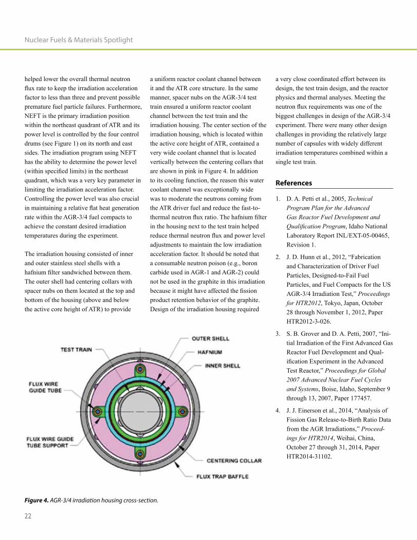
Bradley C. Benefiel
Biology, Utah State University) special-izes in design and process engineering. He commands considerable experience with advanced materials technologies and high-temperature process design at INL. He is well prepared with 20 years of experience in project management and designing and fabricating unique processing equipment and manufacturing facilities. He has experience as the principle engineer on projects ranging from bench-scale research to commer-
Barry H. Rabin
Barry H. Rabin (Ph.D., 1986, Materials Engineering, Rensselaer Polytechnic Insti-tute, B.S., 1982, Metallurgical Engineering, Michigan Technological University) has over 25 years of R&D leadership experience working with a diverse range of advanced materials and manufacturing technologies. In addition to his career at INL, he has started several companies and worked in the private sector. He is currently serving as the National Technical Lead for the DOE/NNSA U.S. High Performance Research Reactor Fuel Development Program. Dr. Rabin has 17 issued patents and over 100 technical publications to his credit.
Ann Marie Phillips
Ann Marie Phillips (B.S., 1984, Mechanical Engineering, University of Minnesota) has over 25 years of project engineering and management experience. Ms. Phillips has led a variety of projects ranging from environmental cleanup to decontamination and decommissioning of nuclear facilities, as well as performing engineering design and analysis. She is currently the Project Engineer/Project Manager for the U.S. High Performance Research Reactor Fuel Devel-opment Program residual stress, mechanical
Phillips has been awarded six patents for her research in environmental management technologies and has over 50 technical publi-cations to her credit.

16
Status of TRISO Fuel
Irradiations in the Advanced Test Reactor
Supporting High-Temperature
Gas-Cooled Reactor Designs

17
Status of TRISO Fuel Irradiations in the Advanced Test Reactor Supporting High-Temperature Gas-Cooled Reactor Designs
Status of TRISO Fuel Irradiations in the Advanced Test
Reactor Supporting High-Temperature Gas-Cooled Reactor Designs Michael Davenport, David A. Petti, and Joe Palmer
Abstract
The Advanced Gas Reactor (AGR) Fuel
is irradiating up to seven experiments on low-enriched uranium tristructural isotropic (TRISO) particle fuel. Irradiations and fuel development are being accomplished at Idaho National Laboratory’s Advanced Test Reactor to support development of the next generation of reactors in the United States. The experiments will be irradiated over the next several years to demonstrate and qualify new TRISO-coated particle fuel for use in high-temperature gas reactors, with goals of providing irradiation performance data to support fuel process development, quali-fying fuel for normal operating conditions, supporting development and validation
transport models and codes, and providing irradiated fuel and materials for post-irra-diation examination and safety testing. The experiments will be irradiated in an inert sweep gas atmosphere, with individual online temperature monitoring and control
capsule fuel performance.
-ation in December 2006 and was completed in November 2009. The second experiment (AGR-2) started irradiation in June 2010 and completed in October 2013. The third and fourth experiments have been combined into a single experiment (AGR-3/4), which started its irradiation in December 2011 and completed in April 2014. Because the purpose of this experiment was to provide
retention in the next generation reactor, the
to begin irradiation in early summer 2017.
Introduction
Fuel development and irradiations are being performed to support development of the next generation of reactors in the United States. The AGR Fuel Development and
irradiation experiments over the next 4 to 5 years to demonstrate and qualify new low-enriched uranium (LEU) TRISO particle fuel for use in high-temperature gas-cooled reactors (HTGRs). Goals of the irradiation experiments include providing irradiation performance data to support fuel process development, qualifying fuel for normal operating conditions, supporting develop-ment and validation of fuel performance and
and providing irradiated fuel and materials for post-irradiation examination (PIE) and safety testing. [1] Each experiment consists of multiple separate capsules and will be irradiated in an inert sweep gas atmosphere with individual online temperature monitor-ing and control of each capsule. The sweep
product monitoring to track fuel performance in each individual capsule during irradiation.
The experiments are specially designed for an exact irradiation position (e.g., location
-ments employ an umbilical tube for housing and protecting the instrumentation and gas lines, including from the individual capsules to the monitoring, control, and data collec-tion system connections at the reactor vessel wall. The overall design concept and sweep gas systems used to control capsule tem-
will be common to all AGR fuel experi-ments. However, the experiment capsule
experiments (i.e., AGR-1 and AGR-2), was
which is a combination of the third and fourth experiments (designated AGR-3/4).
the third irradiation; however, it was also done to accommodate the different types of
large B) to be used. The temperature control system for the third irradiation also included an additional feature for injecting anticipated typical gas impurities in the coolant gas of the HTGR into the gas stream of selected experiment capsules. The mission, capsule design, and support systems for the AGR 3/4
followed by the status and irradiation results to date.

Nuclear Fuels & Materials Spotlight
18
Experiment Description and
Mission
AGR-3/4 was an instrumented lead-type experiment with online active temperature
irradiation experiments commonly per-formed in the Advanced Test Reactor (ATR) are pressurized water loop experiments and static capsule experiments. The pres-surized water loop experiments also have active monitoring and control systems, but the static capsule experiments have only passive monitoring and control; therefore, experimental results are determined after irradiation by examination in a hot cell.
The overall concept for temperature control of experiment capsules, temperature control
-ing system design are all essentially identical to those used on AGR-1 and AGR-2. The experiment capsules utilize an insulating gas jacket with variable mixing of helium and neon sweep gases to control temperature of the fuel during irradiation. New gas tempera-
systems were installed for AGR-3/4 because the existing systems were being used to irra-diate AGR-2 in parallel with the AGR-3/4 irradiation. The new systems are essentially duplicates of the previous systems. Because AGR-3/4 was a combination of the third and fourth experiments, the new system required twice as many temperature control channels
systems used for irradiation of AGR-1 and AGR-2.
The primary mission for AGR-3/4 involved determining the retention behavior of
matrix material (used to form fuel particles into fuel compacts) and the graphite materi-als planned for use in a prismatic HTGR. To complete this mission, design-to-fail (DTF)
particles were included in the AGR-3/4 fuel.
product source necessary for measuring retention behavior of fuel compact matrix material and nuclear-grade graphite core components in an HTGR. This irradiation will also provide (a) fuel performance
particles and (b) irradiated fuel specimens for safety testing and PIE. In this role, the AGR-3/4 irradiation will provide valuable data for development of improved fuel
models to support source term analysis for an HTGR.
AGR-3/4 was irradiated in the northeast
in contrast to the Large B positions used to irradiate AGR-1 (B-10) and AGR-2 (B-12).
These different irradiation positions are shown in Figure 1.
through AGR-7) have tentatively been scheduled for irradiation in the much larger (i.e., 133 mm) ATR NEFT position.
NEFT has higher fast (i.e., 4.4 x 10¹⁴ versus 2.5 x 10¹⁴ n/cm2-s) and thermal (i.e., 1.1 x 10¹⁴ versus 1.61 x 10¹³ n/cm2-s) neutron
a shorter period of time (i.e., approximately 20 to 24 months versus 30 to 36 months in a Large B position). The increased fast to ther-
limit before the fuel burnup goals were
Figure 1. ATR core cross-section showing the AGR fuel irradiation locations.

19
Status of TRISO Fuel Irradiations in the Advanced Test Reactor Supporting High-Temperature Gas-Cooled Reactor Designs
achieved. However, the acceleration factor between these ATR experiments and HTGR
accumulation will remain at or below three to prevent premature fuel particle failures. Because the NEFT position is almost four times the diameter of the Large B positions, AGR-3/4 and other later experiments will be much larger in size and different in shape compared to AGR-1 and AGR-2. This much larger diameter irradiation position also supports irradiating two experiments simultaneously (as previously planned) by doubling them up into irradiations with essentially twice as many capsules and/or twice as many fuel stacks in each capsule. The doubling process will most effectively use the larger position to reduce the required irradiation time and obtain the necessary
as practical. The schedule advantage of using the NEFT position is demonstrated in the irradiation schedules for AGR-2 versus AGR-3/4. Irradiation of AGR-2 started in June 2010 and irradiation of AGR-3/4 started approximately 18 months later in December 2011. However, irradiation of AGR-2 completed in October 2013 and AGR-3/4 completed only 6 months later in April 2014.
Fuel Types and Details
The AGR-3/4 fuel was comprised of two different types of fuel particles. The majority of the fuel particles being used to create the fuel compacts will provide the irradiation temperatures and conditions for the exper-iment. These particles are typically called ‘driver’ particles, because they serve similar functions to the driver fuel elements used in the core of a test reactor. The driver particles were made from uranium oxycarbide-type LEU fuel kernels originally fabricated for AGR-1, with an enrichment level of 19.7%. The individual fuel particles are comprised of fuel kernels that are covered with a layer
of silicon carbide sandwiched between two pyrolytic carbon layers to make up the TRISO-coated fuel particles. The fuel particles are over-coated with a mixture of graphite powder and thermo-set resin and pressed into fuel compacts that are then sintered to remove the volatile compounds in the resin. After being covered with the
diameter fuel kernels result in approximate
The second type of fuel particles in the AGR-3/4 fuel compacts are the DTF particles mentioned earlier. The DTF particles were made using uranium oxy-carbide-type LEU fuel kernels from the same batch used for the driver particles. However, the DTF particles only contain a thin carbon buffer layer and a single highly anisotropic pyrolytic carbon layer, resulting in an approximate overall particle diameter
not contain a silicon carbide layer or the second pyrolytic carbon layer, these particles were anticipated to fail the single pyrolytic carbon layer early in the irradiation and
and graphitic materials in the experiment
was detected by gross gamma detectors in
the particle failures occurred; subsequent PIE analysis of the capsule contents will
desired from the experiment.
The height of the AGR-3/4 fuel compacts was reduced to increase the number of fuel compacts available for the planned PIE tests and measurements and to minimize
compact. The nominal height of 25 mm used in the previous AGR-1 and AGR-2 experiments was decreased to 12.5 mm. However, the diameter of the AGR-3/4
fuel compacts was maintained at the same nominal 12.4-mm value used in the earlier experiments. Because the compact height was reduced, the number of fuel particles in each compact was also reduced from the approximate 4,150 fuel particles in AGR-1 to approximately 1,872 fuel particles total, including 20 DTF particles. The mean total uranium content of an AGR 3/4 fuel compact from both driver and DTF particles was approximately 0.45 grams.
Irradiation Requirements
The 12 capsules in the AGR-3/4 experiment will provide data in different combinations of irradiation temperature, fuel burnup, and
capsules were selected to be controlled based on time-average peak fuel temperatures, with one capsule at <900°C, one capsule at <1000°C, one capsule at <1150°C, two capsules at <1250°C, and one capsule at <1400°C. The other six capsules were con-trolled based on time-average peak graphite material temperatures ranging from 750°C to 1050°C. Controlling fuel temperatures
variations over the life of the irradiation in the surrounding materials. Therefore, using a temperature control strategy for both the fuel and surrounding materials provided data under both conditions to help separate the effects of fuel versus material temperatures
AGR-3/4 utilized the full 1.2-meter active core height in ATR to provide the desired broad range of fuel burn-up and temperature combinations. The initial fuel compact burnup goals were a minimum of 6%
a maximum of less than 19% FIMA. The as-run calculated burnup ranges from 4.78% FIMA for the compact furthest from the core center and experiencing the lowest neutron

Nuclear Fuels & Materials Spotlight
20
plane of the ATR core. The as-run calculated results have been evaluated against the initial goals and have been found to satisfy programmatic requirements.
Experiment Capsule Design
The overall concept for the AGR experiment capsules is very similar for all irradiations. However, design of the experiment capsule,
two irradiations (AGR-1 and AGR-2), was
change was needed primarily to support the different mission and purpose of AGR-3/4 and to accommodate the new type of irradiation position that will be utilized. As indicated earlier, the AGR-3/4 irradiation was performed in the much larger NEFT irradiation position in ATR to reduce the overall irradiation schedule of the AGR experiments. A horizontal cross section of the AGR-3/4 experiment capsule is shown in Figure 2.
Each AGR-3/4 capsule contains four right circular cylindrical fuel compacts nominally 12.4 mm in diameter and 12.5 mm long. The fuel compacts are arranged in a single stack in the center of the capsule, surrounded by a solid ring of fuel matrix material. The next ring is made of one of two nuclear-grade graphite being considered for use in a prismatic HTGR core. An inner insulating gas gap separates the inner graphite from an outer ring of the same nuclear-grade graphite, which operated at relatively cool temperatures from approximately 550 to
migrate completely through the matrix mate-rial and inner graphite rings. The outside diameter of the outer graphite forms the inside boundary of the outer insulating gas gap and provides the primary temperature control during irradiation. Both the inner and outer graphite components have spacer nubs machined on their outside diameters to space them and to form the applicable gas gap for temperature control. The thickness of the outer gas gap varies among the capsules from approximately 0.25 mm to slightly over
the vertical location of the capsules within the ATR core. The thickness variation in the outer gas gap was accomplished by varying the outside diameter of the outer graphite.
As in other AGR experiments, no metal could touch the fuel particles; therefore, thermocouples had to be placed within one of the graphite or matrix material rings within the experiment capsules. Thermocou-ple selection and placement was ultimately based on four criteria. First, temperatures in the outer graphite are relatively low, which
the thermocouples and allow use of smaller (1-mm) diameter (type N) thermocouples. Second, if the smaller size thermocouples were used, there was enough room within the through tubes to nominally accommodate two thermocouples in addition to the inlet and outlet gas lines for each capsule. Third, the smaller size thermocouples are much
in making the relatively tight bends within the very limited space of the gas plenums
-son was the smaller thermocouples provided enough room for three capsules (nominally designed for fuel centerline temperatures of 900°C, 1150°C, and 1250°C) to have a third thermocouple located in the matrix material next to the fuel compacts. These additional thermocouples in the matrix layer provided measured temperature data inside of the inner gas gap. The temperature data from these three thermocouples has been used to more accurately reconcile the thermal analysis model and improve the accuracy of model predictions for fuel, matrix material and inner graphite temperatures for the other capsules.
Figure 2. AGR-3/4 capsule cross section.

21
Status of TRISO Fuel Irradiations in the Advanced Test Reactor Supporting High-Temperature Gas-Cooled Reactor Designs
The through tubes (i.e., pathways for thermocouples and gas lines from the lower capsules to pass through the upper capsules) were positioned in the middle of the outer graphite to minimize their effect on
were included in each capsule for passive
unlikely event that all thermocouples within a capsule were to fail during irradiation. Flux wires were also installed in the graphite to measure both the thermal and fast neutron
Test Train Design
The AGR-3/4 experiment test train was very similar to AGR-1 and AGR-2 and included 12 separate stacked capsules welded together to form the core section of the test train. The core section was welded to an umbilical tube (i.e., termed a leadout at ATR) that houses and protects the gas lines and thermocouple leads. The leadout was routed from the NEFT position straight up from the ATR core to the experiment penetration in the reactor vessel top head. Above the vessel top head, the gas lines and thermocouple leads were connected to their facility counterparts in the temperature monitoring, control, and data collection systems similar to the other AGR experiments. The leadout also vertically located the experiment within the NEFT (shown in Figure 1) in the ATR core. A vertical section of the AGR-3/4 test train is shown in Figure 3.
The original AGR-3 and AGR-4 experiments were both necessary to obtain data at differ-ent combinations of irradiation conditions necessary to support development of the
the desired number of capsules for this irra-diation was twice the nominal six capsules originally envisioned for each irradiation. Doubling the number of capsules required
use of the full 1.2-m ATR active core height (versus the 0.9 m used in AGR-1 and AGR-2). In addition, the overall capsule height (with gas plenums between capsules) was reduced from 150 mm in AGR-1 and AGR-2 to approximately 110 mm. Capsules toward the top and bottom of the core (as well as the fuel compacts within these capsules) in this arrangement had increased vertical neutron
in the decision to reduce the height of the fuel compacts for AGR-3/4.
To maximize the available irradiation space -
shown in Figure 4. The irradiation housing interfaced with the ATR core structure that supports the ATR fuel elements surrounding NEFT; the housing also located the AGR-3/4 test train in the center of NEFT. The neutron
-sive fast neutron damage while achieving the desired fuel burnup. The housing also
Figure 3. AGR-3/4 test train vertical section.
Nuclear Fuels & Materials Spotlight
22
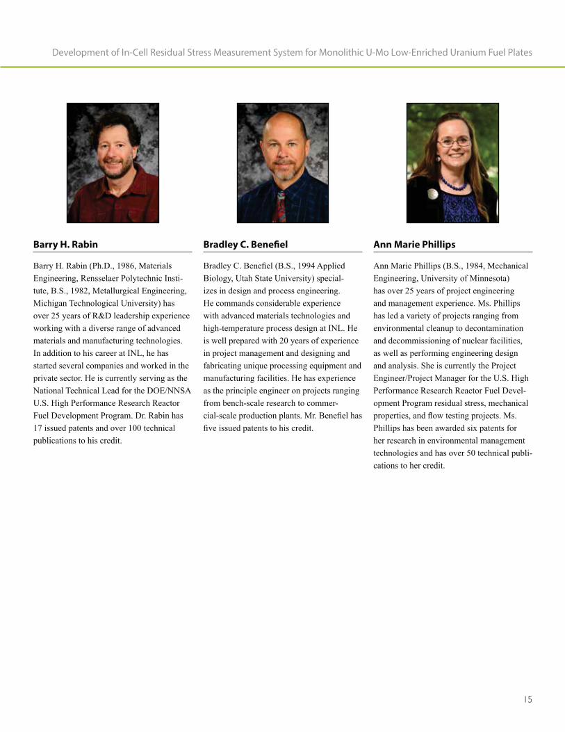
helped lower the overall thermal neutron
factor to less than three and prevent possible premature fuel particle failures. Furthermore, NEFT is the primary irradiation position within the northeast quadrant of ATR and its power level is controlled by the four control drums (see Figure 1) on its north and east sides. The irradiation program using NEFT has the ability to determine the power level
quadrant, which was a very key parameter in limiting the irradiation acceleration factor. Controlling the power level was also crucial
rate within the AGR-3/4 fuel compacts to achieve the constant desired irradiation temperatures during the experiment.
The irradiation housing consisted of inner and outer stainless steel shells with a
The outer shell had centering collars with spacer nubs on them located at the top and bottom of the housing (above and below the active core height of ATR) to provide
a uniform reactor coolant channel between it and the ATR core structure. In the same manner, spacer nubs on the AGR-3/4 test train ensured a uniform reactor coolant channel between the test train and the irradiation housing. The center section of the irradiation housing, which is located within the active core height of ATR, contained a very wide coolant channel that is located vertically between the centering collars that are shown in pink in Figure 4. In addition to its cooling function, the reason this water coolant channel was exceptionally wide was to moderate the neutrons coming from the ATR driver fuel and reduce the fast-to-
in the housing next to the test train helped
adjustments to maintain the low irradiation acceleration factor. It should be noted that a consumable neutron poison (e.g., boron carbide used in AGR-1 and AGR-2) could not be used in the graphite in this irradiation
product retention behavior of the graphite. Design of the irradiation housing required
a very close coordinated effort between its design, the test train design, and the reactor physics and thermal analyses. Meeting the
biggest challenges in design of the AGR-3/4 experiment. There were many other design challenges in providing the relatively large number of capsules with widely different irradiation temperatures combined within a single test train.
References
1. D. A. Petti et al., 2005, Technical Program Plan for the Advanced Gas Reactor Fuel Development and
, Idaho National Laboratory Report INL/EXT-05-00465, Revision 1.
and Characterization of Driver Fuel Particles, Designed-to-Fail Fuel Particles, and Fuel Compacts for the US
Proceedings for HTR2012, Tokyo, Japan, October 28 through November 1, 2012, Paper HTR2012-3-026.
-tial Irradiation of the First Advanced Gas Reactor Fuel Development and Qual-
Proceedings for Global 2007 Advanced Nuclear Fuel Cycles and Systems, Boise, Idaho, September 9 through 13, 2007, Paper 177457.
Fission Gas Release-to-Birth Ratio Data Proceed-
ings for HTR2014, Weihai, China, October 27 through 31, 2014, Paper HTR2014-31102.
Figure 4. AGR-3/4 irradiation housing cross-section.

23
Status of TRISO Fuel Irradiations in the Advanced Test Reactor Supporting High-Temperature Gas-Cooled Reactor Designs
David Petti
David Petti, Ph.D., is a graduate of the MIT Nuclear Engineering Department and has been recognized as a Fellow at both Idaho National Laboratory and the American Nuclear Society. With over 30 years of experience in nuclear technology, he currently serves as director of the Nuclear Fuels and Materials Division and as the Nuclear Science and Technology’s chief scientist. Previously, he held the position of Co-National Technical Director for DOE’s Advanced Reactor Technologies Program. He has direct experience with research and development for fuels, graphite, high-tem-perature materials, and design and safety evaluation methods. Dr. Petti is an interna-tionally recognized expert in coated particle fuel technology.
Joe Palmer
Joe Palmer (B.S., 1987, Mechanical Engineering, Brigham Young University; M.S., 1988, Mechanical Engineering, Brigham Young University) is a mechanical design engineer at INL. He designs tempera-ture-controlled experiments and Hydraulic Shuttle Irradiation System experiments. Mr. Palmer has over 25 years of extensive experience in reactor experiment design, chemical process equipment design, dynamic
element stress, and thermal analysis. He also holds a Professional Engineering license in Idaho.
Michael Davenport
Michael Davenport is a Project Manager/Technical Lead with the Advanced Reactor Technologies (ART) Irradiation Programs at INL. In this capacity, he is responsible for managing the design, fabrication, and irradiation of ART experiment test trains. Davenport holds a M.S. in Project Manage-ment from the Keller Graduate School of Management (Devry) and a B.S. in Man-agement from the University of Phoenix. Davenport has 9 years of experience in the nuclear navy, 14 years of experience as an ATR Shift Supervisor, and 8 years of experi-ence in performing project management for ART irradiations.

24
High-Temperatur
Safety Testing of Irradiated
AGR-1 TRISO Fuel

25
High-Temperature Safety Testing of Irradiated AGR-1 TRISO Fuel
High-Temperature Safety Testing of Irradiated AGR-1 TRISO FuelJohn D. Stempien, Paul A. Demkowicz, Edward L. Reber, and Cad L. Christensen
Introduction
The purpose of the Advanced Gas Reactor
Program is to design, fabricate, irradiate, analyze, and qualify tristructural isotropic (TRISO)-coated particle fuel for use in high-temperature gas-cooled reactors (HTGRs) in the United States [1]. In a recently completed test, three intact irra-diated fuel compacts were heated under a temperature transient characteristic of a core-conduction cool-down event in an
products (i.e., Ag, Cs, Eu, Sb, and Sr) and
as a function of test time.
A spherical irradiated fuel element, designated AVR-91/31, was tested in a
Federal Republic of Germany [2]. The TRISO-coated particle fuel in this sphere featured a UO2 kernel, and prior to the test, the sphere had been irradiated to a burnup of
the shape of a calculated design-basis core-conduction cool-down event shifted up to a maximum temperature of 1700°C compared to 1600°C for the design basis. The AVR-91/31 test was particularly noteworthy in that approximately 20 TRISO failures occurred, based on the level of Kr release. This is a higher failure fraction than was observed during isothermal tests of similar AVR fuel. Part of the motivation for the AGR safety test reported here was to determine if AGR fuel performed differently during a temperature transient than during high-temperature, isothermal exposure.
Sample Selection and Experiment
Three cylindrical fuel compacts from the
selected for simultaneous heating in the Fuel Accident Condition Simulator (FACS) furnace at Idaho National Laboratory. All kernels were a heterogeneous mixture of uranium oxide (UO) and uranium carbide (UCO). Compacts selected for this test used
(SiC) layers deposited at lower temperatures in an argon-hydrogen mixture that produced
reduce SiC defects caused by uranium dis-persion [3,4]. The three compacts were from the same AGR-1 irradiation capsule and each compact contained approximately 4,126 fuel particles (i.e., a volume packing fraction of 36 %) with a uranium enrichment of 19.7 wt %. The compacts had similar burnup and time-average, volume-average (TAVA) temperature. The Ag-110m inventory in the compacts was determined by gamma spectrometry and compared to predicted inventories to estimate the fraction of Ag that was retained in each compact during irradiation [5]. Results indicated similar levels of Ag retention in the three compacts. Properties for each of the three compacts used in the temperature transient safety test are summarized in Table I.
The FACS furnace is located in the main hot cell at the Hot Fuels Examination Facility at Idaho National Laboratory. A tantalum sample holder held the three compacts for simultaneous heating under a helium sweep
products. The condensation plates were swapped at various points during the test and analyzed following test completion. A
counted Kr-85 throughout the test. Addi-tional information on the FACS furnace is available in [6].
Results and Discussion
The plots in Figures 1 through 3 show
and release rates as a function of time for the transient test of AGR-1 Variant 3 Compacts 1-4-2, 1-1-3, and 1-1-1. Results from three previous isothermal safety tests [6] of individual AGR-1 Compacts 6-4-1 (base-line variant), 4-3-3 (Variant 3), and 4-3-2 (Variant 3) are also plotted for comparison. The transient test results are plotted such that time t = 0 marks the beginning of the transient rise in temperature. The previously
Table I. AGR-1 compact irradiation properties.
Compact Name
Compact Burnup
(% FIMA)
Compact Fast Neutron Fluence
(×1025 n/m2, E > 0.18 MeV)TAVA Irradiation Temperature (°C)
Retained Ag-110m Fraction
1-4-2 14.9 3.01 1045 0.76
1-1-3 15.3 2.86 1018 0.80
1-1-1 15.2 2.81 1017 0.79
Nuclear Fuels & Materials Spotlight
26
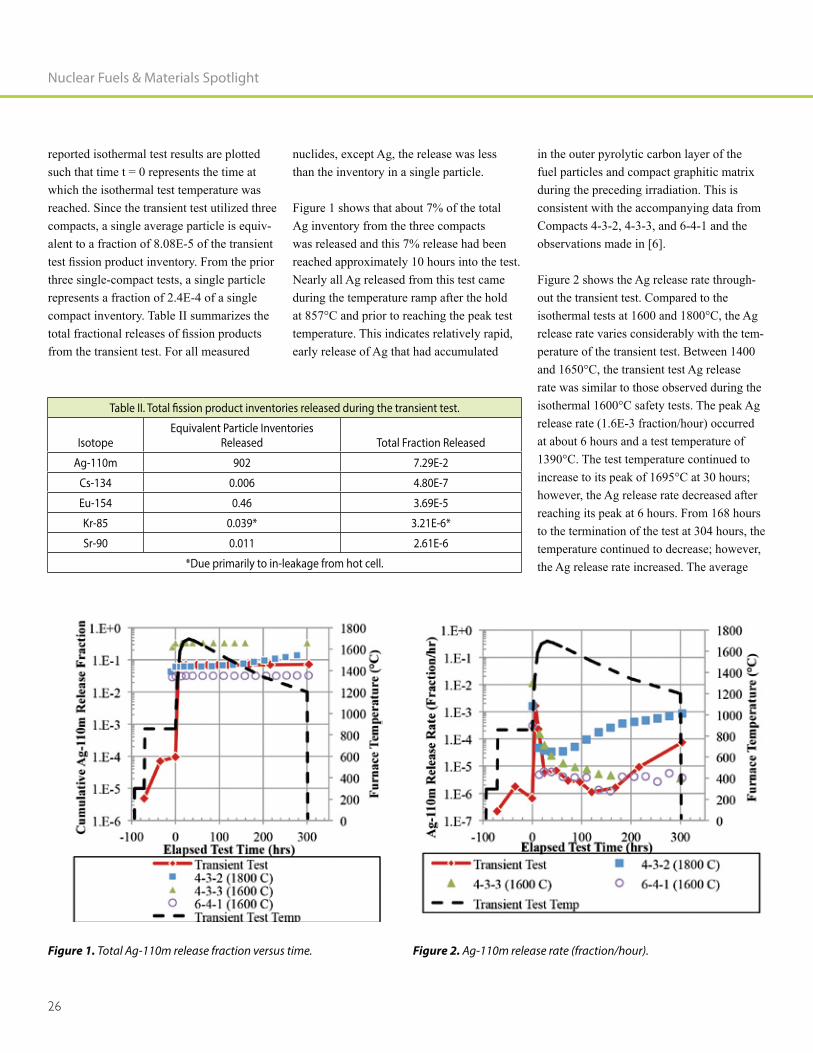
reported isothermal test results are plotted such that time t = 0 represents the time at which the isothermal test temperature was reached. Since the transient test utilized three compacts, a single average particle is equiv-alent to a fraction of 8.08E-5 of the transient
three single-compact tests, a single particle represents a fraction of 2.4E-4 of a single compact inventory. Table II summarizes the
from the transient test. For all measured
nuclides, except Ag, the release was less than the inventory in a single particle.
Figure 1 shows that about 7% of the total Ag inventory from the three compacts was released and this 7% release had been reached approximately 10 hours into the test. Nearly all Ag released from this test came during the temperature ramp after the hold at 857°C and prior to reaching the peak test temperature. This indicates relatively rapid, early release of Ag that had accumulated
in the outer pyrolytic carbon layer of the fuel particles and compact graphitic matrix during the preceding irradiation. This is consistent with the accompanying data from Compacts 4-3-2, 4-3-3, and 6-4-1 and the observations made in [6].
Figure 2 shows the Ag release rate through-out the transient test. Compared to the isothermal tests at 1600 and 1800°C, the Ag release rate varies considerably with the tem-perature of the transient test. Between 1400 and 1650°C, the transient test Ag release rate was similar to those observed during the isothermal 1600°C safety tests. The peak Ag release rate (1.6E-3 fraction/hour) occurred at about 6 hours and a test temperature of 1390°C. The test temperature continued to increase to its peak of 1695°C at 30 hours; however, the Ag release rate decreased after reaching its peak at 6 hours. From 168 hours to the termination of the test at 304 hours, the temperature continued to decrease; however, the Ag release rate increased. The average
Table II. Total fission product inventories released during the transient test.
IsotopeEquivalent Particle Inventories
Released Total Fraction Released
Ag-110m 902 7.29E-2
Cs-134 0.006 4.80E-7
Eu-154 0.46 3.69E-5
Kr-85 0.039* 3.21E-6*
Sr-90 0.011 2.61E-6
*Due primarily to in-leakage from hot cell.
Figure 1. Total Ag-110m release fraction versus time. Figure 2. Ag-110m release rate (fraction/hour).
27
plates exchanged in the test was 2.4E-5 fraction/hour, and the average temperature over these three plates was 1299°C. This suggests a region where the Ag release rate is inversely proportional to the test temperature. This apparent inverse-temperature behavior is consistent with behavior noted in the safety test of AGR-1 Compact 4-2-2 [7], where the test temperature was varied between 1000 and 1600°C, and the Ag-110m release rates were found to be highest in the 1100 to 1300°C range.
A fraction of 4.8E-7 of the Cs-134 inventory was released from the compacts during the transient test. This is equivalent to 0.6% of the inventory from a single, average particle, and indicates that no SiC layer degradation occurred. Despite a peak temperature of 1695°C, the transient test Cs-134 fractional release is similar to that of the isothermal 1600°C test of Compact 4-3-3. Most Cs release occurred during the ramp to peak
temperature following the hold at 857°C. The two highest Cs release rates were 3.8E-9 fraction/hour from the plate exchanged at 1600°C and 2.7E-9 fraction/hour from the plate exchanged at 1690°C. Since little Cs release occurred after peak test temperature, this indicates that Cs releases during the test were limited to Cs that had migrated out beyond the fuel particle SiC layers during irradiation.
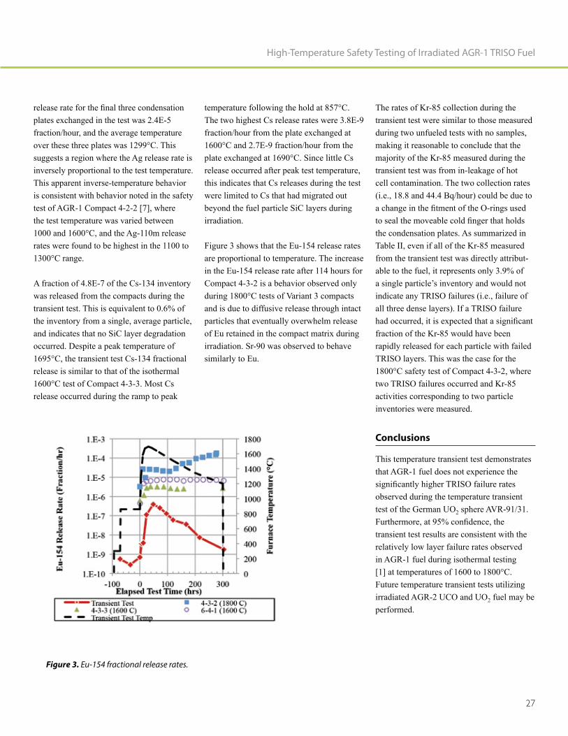
Figure 3 shows that the Eu-154 release rates are proportional to temperature. The increase in the Eu-154 release rate after 114 hours for Compact 4-3-2 is a behavior observed only during 1800°C tests of Variant 3 compacts and is due to diffusive release through intact particles that eventually overwhelm release of Eu retained in the compact matrix during irradiation. Sr-90 was observed to behave similarly to Eu.
The rates of Kr-85 collection during the transient test were similar to those measured during two unfueled tests with no samples, making it reasonable to conclude that the majority of the Kr-85 measured during the transient test was from in-leakage of hot cell contamination. The two collection rates (i.e., 18.8 and 44.4 Bq/hour) could be due to
the condensation plates. As summarized in Table II, even if all of the Kr-85 measured from the transient test was directly attribut-able to the fuel, it represents only 3.9% of a single particle’s inventory and would not indicate any TRISO failures (i.e., failure of all three dense layers). If a TRISO failure
fraction of the Kr-85 would have been rapidly released for each particle with failed TRISO layers. This was the case for the 1800°C safety test of Compact 4-3-2, where two TRISO failures occurred and Kr-85 activities corresponding to two particle inventories were measured.
Conclusions
This temperature transient test demonstrates that AGR-1 fuel does not experience the
observed during the temperature transient test of the German UO2 sphere AVR-91/31.
transient test results are consistent with the relatively low layer failure rates observed in AGR-1 fuel during isothermal testing [1] at temperatures of 1600 to 1800°C. Future temperature transient tests utilizing irradiated AGR-2 UCO and UO2 fuel may be performed.
High-Temperature Safety Testing of Irradiated AGR-1 TRISO Fuel
Figure 3. Eu-154 fractional release rates.

Nuclear Fuels & Materials Spotlight
28
Paul Demkowicz
Paul Demkowicz, Ph.D., is a Distinguished Staff Scientist at INL, where he has worked for the last 13 years. His current focus is on development and characterization of fuels for advanced nuclear reactors. Dr. Demko-wicz is the technical lead for the U.S. DOE Advanced Gas Reactor Fuel Development
is fabricating, irradiating, and performing post-irradiation examination and testing on tristructural isotropic-coated particle fuel, with the goal of qualifying this fuel form for use in high-temperature gas-cooled reactors. The results of this ongoing effort have received international attention for the noteworthy technical successes and dramatic demonstration of superb fuel performance under extreme temperatures. He holds a B.S. degree in Ceramic Engineering from the University of Washington and M.S. and Ph.D. degrees in Materials Science and Engineering from the University of Florida.
John D. Stempien
John D. Stempien (Ph.D., 2015, Nuclear Engineering, Massachusetts Institute of Technology; M.S., 2011, Nuclear Engineering, Massachusetts Institute of Technology; B.S., 2008, Chemistry Uni-versity of Vermont) is the technical lead for post-irradiation examination of tri-structural isotropic (TRISO)-coated particle fuel within the advanced gas reactor fuel development
joining INL in 2015, he conducted research in a variety of areas, including tritium transport and coolant chemistry modeling in
examination and simulations of TRISO fuel behavior, and post-irradiation examination and physical properties testing of composite silicon carbide fuel claddings for light water reactors.
References
1. P. A. Demkowicz, J. D. Hunn, R. N. Morris et al., 2015, AGR-1 Post Irradiation Examination Final Report, INL/EXT-15-36407, Revision 0, Idaho National Laboratory.
2. W. Schenk, D. Pitzer, and H. Knauf, 1993, Simulation der max. MOD-UL-Störfallaufheizkurve (AVR-GLE 3, 09/20) und deren Extrapolation auf 1700°C (AVR-GLE 3, 91/31), IWE-TN-17/93, Forschungszentrum Jülich GmbH (KFA).
3. J. D. Hunn, G. E. Jellison Jr., and R. A.
carbon optical anisotropy and density during processing of coated particle
Journal of Nuclear Materials, 374, pp. 445-452.
4. B. P. Collin, 2015, AGR-1 Irradiation Test Final As-Run Report, INL/EXT-10-18097, Revision 3, Idaho National Laboratory.
-ual Compact Fission Product Inventory and Burnup for the AGR-1 TRISO Experiment using Gamma Spectrom-
National Laboratory.
6. P. A. Demkowicz, E. L. Reber, D. M. -
perature safety tests of AGR-1 TRISO fuel with the Fuel Accident Condition
Journal of Nuclear Materials, 464, pp. 320.
7. J. D. Hunn, R. N. Morris, C. A. Baldwin et al., 2015, PIE on Safety-Tested AGR-1 Compact 4-2-2, ORNL/TM-2015/033, Revision 0, Oak Ridge National Laboratory.

29
Edward L. Reber
Edward L. Reber (Ph.D., 1994, Nuclear Physics, Florida State University, M.S., 1992, Nuclear Physics, Florida State University; B.S., 1987, Physics, State University of New York at Geneseo) is a distinguished scientist at INL. He has over 20 years of experience working on projects involving nuclear experiments and analysis. These diverse projects include nuclear nonproliferation, basic nuclear research, spent nuclear fuel characterization, national security, gamma-ray spectroscopy, in-reactor
nuclear fuel post-irradiation examination, and being the technical lead for the Idaho Explosives Detection System. He has author or co-authored 40 peer-reviewed journal articles and has been awarded eight U.S. Patents. In 2005, he received the Christopher Columbus Fellowship Foundation’s Home-land Security Award in the Field of Border/Transportation Security.
High-Temperature Safety Testing of Irradiated AGR-1 TRISO Fuel
Cad Christensen
Cad L. Christensen (A.A.S., 2001, Diesel Power Generation Technology, Idaho State University; B.S., 2012, Industrial Engineer-ing, University of Idaho) has worked many years as an automotive and diesel technician before transferring to the Post-Irradiation Examination division at INL in 2010. He helped with disassembly, examination, and metallography of numerous projects at the Hot Fuel Examination Facility while
engineering organization at the Hot Fuel Examination Facility overseeing post irradia-tion examination equipment.

30
SiC Grain Boundary Character
and Fission Product Transport
in Irradiated TRISO
Fuel Particles
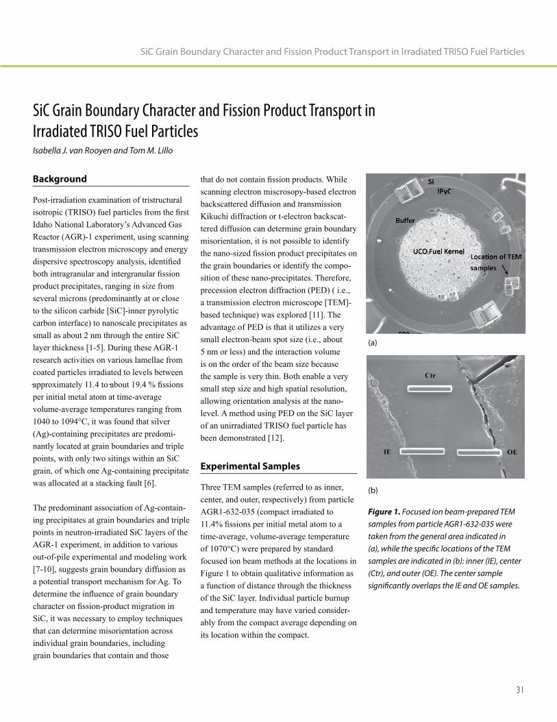
31
SiC Grain Boundary Character and Fission Product Transport in Irradiated TRISO Fuel Particles
SiC Grain Boundary Character and Fission Product Transport in
Irradiated TRISO Fuel ParticlesIsabella J. van Rooyen and Tom M. Lillo
Background
Post-irradiation examination of tristructural
Idaho National Laboratory’s Advanced Gas Reactor (AGR)-1 experiment, using scanning transmission electron microscopy and energy
product precipitates, ranging in size from several microns (predominantly at or close to the silicon carbide [SiC]-inner pyrolytic carbon interface) to nanoscale precipitates as small as about 2 nm through the entire SiC layer thickness [1-5]. During these AGR-1 research activities on various lamellae from coated particles irradiated to levels between
per initial metal atom at time-average volume-average temperatures ranging from 1040 to 1094°C, it was found that silver (Ag)-containing precipitates are predomi-nantly located at grain boundaries and triple points, with only two sitings within an SiC grain, of which one Ag-containing precipitate was allocated at a stacking fault [6].
The predominant association of Ag-contain-ing precipitates at grain boundaries and triple points in neutron-irradiated SiC layers of the AGR-1 experiment, in addition to various out-of-pile experimental and modeling work [7-10], suggests grain boundary diffusion as a potential transport mechanism for Ag. To
SiC, it was necessary to employ techniques that can determine misorientation across individual grain boundaries, including grain boundaries that contain and those
scanning electron miscrosopy-based electron backscattered diffusion and transmission Kikuchi diffraction or t-electron backscat-tered diffusion can determine grain boundary misorientation, it is not possible to identify
the grain boundaries or identify the compo-sition of these nano-precipitates. Therefore, precession electron diffraction (PED) ( i.e., a transmission electron microscope [TEM]-based technique) was explored [11]. The advantage of PED is that it utilizes a very small electron-beam spot size (i.e., about 5 nm or less) and the interaction volume is on the order of the beam size because the sample is very thin. Both enable a very small step size and high spatial resolution, allowing orientation analysis at the nano-level. A method using PED on the SiC layer of an unirradiated TRISO fuel particle has been demonstrated [12].
Experimental Samples
Three TEM samples (referred to as inner, center, and outer, respectively) from particle AGR1-632-035 (compact irradiated to
time-average, volume-average temperature of 1070°C) were prepared by standard focused ion beam methods at the locations in Figure 1 to obtain qualitative information as a function of distance through the thickness of the SiC layer. Individual particle burnup and temperature may have varied consider-ably from the compact average depending on its location within the compact.
Figure 1. Focused ion beam-prepared TEM samples from particle AGR1-632-035 were taken from the general area indicated in (a), while the specific locations of the TEM samples are indicated in (b): inner (IE), center (Ctr), and outer (OE). The center sample significantly overlaps the IE and OE samples.
(a)
(b)

Nuclear Fuels & Materials Spotlight
32
Experimental Results: Grain
Boundary Data for Grain
Boundaries Containing Fission
Products
product precipitates that was analyzed for composition and associated grain boundary information, as an example of the type of information that was obtained from analysis areas. In this particular area, seven grain
precipitates. Even though all segments were
each segment were not necessarily the same (Table 1). Most segments contained palla-dium (Pd) with the exception of Boundary Segments 2 and 3, which contain only Ag. In this example, it appears that the grain boundary parameters, which determine grain boundary energy and grain boundary atomic
be present on a particular grain boundary segment. Boundary Segments 1, 2, 3, and 4 in Table 1 are all considered to be random, high-angle grain boundaries; all are expected to be relatively high energy and with no
because they are random grain boundaries and yet they exhibit elevated levels of
must possess unique characteristics, energy, or atomic structures, which allow preferen-
Figure 2. Example area showing grain boundary precipitates that were analyzed for composition and grain boundary character: (a) TEM image, (b) scanning transmission electron microscopy image using the HAADF detector, and (c) corresponding orientation image. The arrow in each image denotes the same reference point [13].
Table 1. Summary of fission product precipitate information and associated grain boundary information (• indicates the presence of fission product) [13].
Grain Boundary Segment Angle Axis CSL designation Pd Ag U
1 33.6 20 13 -13 — • •
2 45.7 5 13 15 — •
3 54.2 18 2 -15 — •
4 43.6 4 16 -19 — •
5 38.7 1 0 1 9 •
6 56.8 20 -1 23 — •
7 13.8 -7 23 -18 — •

33
SiC Grain Boundary Character and Fission Product Transport in Irradiated TRISO Fuel Particles
Experimental Results: Summary
of Precipitate Composition and
Associated Grain Boundary
Information
SiC grain boundary precipitates were most prevalent near the IPyC layer (Figure 3, inner sample), which is as expected because this location is nearest the source of the
elements and their combinations revealed interesting trends related to grain boundary type. Precipitates that contain only Pd seem to occur on all types of grain boundaries, with preference for random, high-angle grain boundaries. However, when Pd was found in conjunction with either Ag or uranium (U), low-angle grain boundaries no longer appear
product precipitates. Also, Ag by itself was found to only occur on random, high-angle grain boundaries and never on low-angle or coincident site lattice (CSL)-related grain boundaries. The larger atomic radii of Ag or U can potentially increase the strain energy of such precipitates on low energy boundaries to the point where they are no longer energetically favorable. The almost complete lack of solubility of Ag in SiC [16] (i.e., a thermodynamic consideration) may also prevent precipitation on low angle and CSL-related boundaries.
The presence of Ag only precipitates when Pd is close by remains unexplained. Another study [14] also shows that Ag is capable of diffusing through SiC, even when Pd is not present. However, if Pd were available, as in the present study, then one would expect
complete solubility of Ag in Pd [15] if the precipitates are metallic solid solutions. If a particular boundary possesses a grain boundary energy and structure amenable for Ag-only precipitates (i.e., random, high-an-gle grain boundaries; Figure 4), then Pd
would not be expected to be excluded from also being present on this boundary, because it can precipitate on grain boundaries of all types and energies. Thus, it is not clear what combination of grain boundary energy and structure could allow precipitation of Ag and prevent Pd from also precipitating. However, Pd may actually be present in the Ag-only
precipitates, but at levels below the limits of detection for the characterization methods. The same may be said of the Pd-only precip-itates, Ag may actually be present but below the limits of detection. If so, then the grain boundary structure and/or energy of random, high-angle grain boundaries somehow
Figure 3. Summary of the grain boundary types associated with fission products [13].
Figure 4. Graphical presentation showing the associations of fission products and U with grain boundary types.

Nuclear Fuels & Materials Spotlight
34
product precipitate, again implying that not all random, high-angle grain boundaries should be considered equivalent or even similar when it comes to segregation and
Conversely, if the precipitates are actually silicides, then it might be possible to have Ag in solid solution in a Pd-silicide produce
solid solution in an Ag-silicide to produce the Ag-only precipitates. However, Ag-sili-cides do not seem to occur [17]. Therefore, the existence of Ag-only precipitates found in this study is unexplained at this time and will require determination of not only the crystal structure of the Ag-only precipitates
product elements during (and after) irradi-ation. A more detailed understanding of the grain boundary energy and grain boundary structure also will be required.
Conclusions
The PED method developed earlier on unirradiated SiC was successfully used to determine the grain boundary misorienta-tion angle and axis in the SiC layer of an irradiated TRISO fuel particle. It was also successfully demonstrated that detailed grain boundary characteristics in the vicinity
products. These results show great promise for revealing the relationship between SiC
migration through the SiC layer of
• Fission product precipitates were com-monly found on random, high-angle grain boundaries and to a lesser degree at low-angle and CSL-related grain bound-aries.
• Pd was found at all types of grain bound-aries, but most prominently on random, high-angle grain boundaries.
• Pd-U and Pd-Ag precipitates were found on CSL-related and random, high angle grain boundaries, but not on low-angle grain boundaries.
• Precipitates containing only Ag were only found on random, high-angle grain boundaries (i.e., not on either low-angle or CSL-related grain boundaries). The reason for Ag-only precipitates is not known.
This study was expanded to obtain informa-tion from more TRISO particles from the AGR-1 experiment to enable comparative datasets. These results are now being
advanced microscopy report.
It is further recommended that efforts be made to analyze the grain boundary plane in addition to the other grain boundary
-tion through the SiC layer of TRISO and,
irradiation.
Acknowledgements
This work was sponsored by the U.S.
Energy, under U.S. Department of
DE-AC07-05ID14517, as part of the Very High-Temperature Reactor Development Program and as part of an Nuclear Science User Facilities Rapid Turnaround Experi-ment.
References
1. I. J. van Rooyen, D. Janney, B. Miller, P. Demkowicz, and J. Riesterer, 2014,
irradiated TRISO coated particles from the AGR-1 experiment: A preliminary
Nuclear Engineering and Design, 271, pp. 114-122.
2. I. J. van Rooyen, Y. Q. Wu, and T. M.
Palladium in Irradiated TRISO Coated
Journal of Nuclear Materials, 446, pp. 178-186.
3. B. Leng, I. van Rooyen, Y. Wu, I. Szlu-
EDS Analysis of Fission Products in Irradiated TRISO Coated Particles of the
Journal of Nuclear Materials, 475, pp. 62-70.
4. I. J. van Rooyen, E. J. Olivier, and J.
the Fission Products Silver, Palladium and Cadmium in Neutron Irradiated SiC
Journal of Nuclear Materials, 476, pp. 93-101.
5. T. M. Lillo and I. J. van Rooyen, 2015,
SiC layer of neutron irradiated TRISO Journal of Nuclear Materials,
460, pp. 97-106.
6. P. A. Demkowicz, J. D. Hunn, R. N. Morris, I. van Rooyen, T. Gerczak, J. M.
Post Irradiation, Examination Final
National Laboratory.
7. J. Deng, H. Ko, P. Demkowicz, D. Morngan, and I. Szlufarska, 2015,
polycrystalline SiC in TRISO coated Journal of Nuclear Materials,
467, pp. 332-340.

35
SiC Grain Boundary Character and Fission Product Transport in Irradiated TRISO Fuel Particles
8. H. Ko, J. Deng, I. Szlufarska, and D.
high energy grain boundaries: Kinetic
Computational Material Science, 121, pp. 248-257.
9. I. J. van Rooyen, H. Nabielek, J. H. Neethling, M. J. Kania, and D. A.
elusive Ag transport mechanism in
HTR2014-3-1261, Proceedings of HTR2014, Weiha, China, October 27 through 31, 2014.
10. D. Schrader, S. M. Khalil, T. Gerzcak, T. R. Allen, A. J. Heim, I. Szlufarska, and D. Morgan, 2011, Journal of Nuclear Materials, 408, pp. 257–271.
11. I. J. van Rooyen, T. Lillo, and Y. Wu, -
graphic parameters of irradiated SiC to
ATR NSUF User’s Week 2015, Idaho Falls, June 24, 2015.
12. T. M. Lillo, I. J. van Rooyen, and Y.
diffraction for SiC grain boundary characterization in unirradiated TRISO
Nuclear Engineering and Design, 305, pp. 277–283, http://dx.doi.org/10.1016/j.nucengdes.2016.05.027.
13. T. M. Lillo, and I. J. van Rooyen, 2016,
Character on Fission Product Transport Journal
of Nuclear Materials, 473, pp. 83-92, 10.1016/j.jnucmat.2016.01.040.
14. E. Lopez-Honorato, H. Zhang, D. Yang, P. Xiao, 2011, Journal of American Ceramics Society, 94, pp. 3064-3071.
ASM Alloy Phase Diagrams Center, P. Villars (editor-in-chief) and H. Okamoto and K. Cenzual
(section editors), http://www1.asminter-national.org/AsmEnterprise/APD, ASM International, Materials Park, Ohio..
16. S. Hassam, J. Ågren, M. Gaune Escard,
ASM Alloy Phase Diagrams Center, P. Villars (editor-in-chief) and H. Okamoto and K. Cenzual, (section editors), http://www1.asminternational.org/ AsmEnterprise/APD, ASM Interna-tional, Materials Park, Ohio.
17. E. J. Olivier and J. H. Neethling, 2013, Journal of Nuclear Materials, 432, pp. 252-260.

Nuclear Fuels & Materials Spotlight
36
Isabella J. van Rooyen
Isabella J van Rooyen ( Ph.D., 2011, Physics, Nelson Mandela Metropolitan Uni-versity; M.S.c, 1988, Metallurgy, University of Pretoria; MBA, 2003, Business Adminis-tration, North West University; B.S.c, 1981, Metallurgy, University of Pretoria; B.S.c. Honors, 1983, Metallurgy, University of Pretoria) is a Distinguished Staff Scientist at INL where she leads the advanced electron microscopy, and micro-analysis examina-tions for the Advanced Gas Reactor TRISO fuel development program from 2011. Addi-tionally she is also the principal investigator (PI) of an additive manufacturing U3Si2 fuel research project, the PI or co-PI of 4 research
users facility as well as a co-PI on a Nuclear Energy University Program research project focusing on SiC-ODS alloy gradient nano composite cladding. Prior to joining INL, Dr. van Rooyen held various technical leadership roles in the nuclear, aerospace and automotive industries in South Africa, with most notable the research at Pebble Bed Modular Reactor (PBMR) Company and NECSA. Dr. van Rooyen has in excess of 30 peer reviewed journal publications, more than 40 conference papers and presentations,
-
one patent application in progress.
Tom Lillo
Thomas Lillo (Ph.D., 1994, Metallurgical Engineering, Michigan Technological University) is a staff scientist in the Depart-ment of Materials Science and Engineering
characterization of high-temperature metallic alloys, intermetallic alloys, ceramics, and composites for power generation appli-cations. He has expertise in the areas of TEM, SEM, OIM, and x-ray diffraction. Additionally, he is directing a study on the high-temperature creep behavior of alloys for the intermediate heat exchanger of the very high-temperature reactor. Dr. Lillo has in excess of 30 technical publications and has collaborated on six patents.

37
SiC Grain Boundary Character and Fission Product Transport in Irradiated TRISO Fuel Particles

38
3D Modeling of
Missing Pellet Surface
Defects in BISON

39
3D Modeling of Missing Pellet Surface Defects in BISON
3D Modeling of Missing Pellet Surface Defects in BISONB. W. Spencer, R. L. Williamson, D. S. Stafford, S. R. Novascone, J. D. Hales, and G. Pastore
Introduction
The metallic cladding that encases light water reactor (LWR) fuel serves as a
Pellet-cladding interaction (PCI), which can be caused by a combination of mechanical interactions between fuel and cladding and chemical reactions, is one of the major causes of cladding failure [1]. The cladding stresses induced by the mechanical PCI are
A type of defect, known as a missing pellet surface (MPS) in which a portion of the side of a pellet has been removed due to accidental machining or chipping, has been
failure [1,2] due to its local effects on pellet geometry.
Because of the nature of the defect geometry, modeling the effects of an MPS defect requires a local three-dimensional (3D) model of the defect region, but the model must also incorporate the effects of the full fuel rod. This paper presents an approach to couple a two-dimensional (2D) model of the full rod with a local 3D model of the defec-tive pellet region using the BISON code and a demonstration of this approach on boiling water reactor (BWR) fuel subjected to a local rapid increase in power due to a control blade withdrawal.
Models
The thermo-mechanical response of LWR nuclear fuel in the reactor environment is affected strongly by the composition of the
products into the plenum gas, which is initially helium. To accurately represent the response of a local region of a fuel rod, such as the region adjacent to an MPS defect, one must account for the response of the entire rod. To account for this, two separate models
element model of a full fuel rod (shown in Figure 1[a]), and a local model of the region of interest (shown in Figure 1[b–d]).
Figure 1. Models employed in this work: (a) 2D axisymmetric model of a full rod; (b) 3D representation of a pellet with an MPS defect; (c) zoomed-in view of 3D model of fuel and cladding in the vicinity of the MPS defect; and (d) 2D model of MPS-affected fuel and cladding.
(a) (b) (c) (d)

Nuclear Fuels & Materials Spotlight
40
The full rod model and the local model are both run through the full irradiation history. A one-way coupling strategy is employed
gas released, total plenum volume, and ple-num gas temperature are transferred from the full rod model to the local model. This set of
boundary conditions and plenum gas thermal conductivity needed in the local model.
allows the combined global and local models to represent the effects of transients that affect primarily local regions of the rod and transients that are more global in nature. This has been demonstrated recently on an analysis of BWR fuel [3] for which excerpts are summarized in the following:
Control blades are employed in BWRs to control the power. During the course of oper-ation, these control blades are withdrawn in small increments to adjust the power. These
small adjustments have a minimal impact on the global response of the full fuel rod,
increase in the power in the vicinity of the tip of the control blade.
The proposed coupling strategy was employed to represent a BWR fuel rod containing an MPS defect irradiated for one cycle in a position away from the
to a position adjacent to a control blade. Power at the MPS defect location is initially suppressed due to the control blade, but the
is withdrawn a small amount. The power is then held at that level, until the power in the full rod is increased by 50% to simulate a ramp to high power. While the control blade withdrawal event has a negligible effect on
conductivity.
Results
Figure 2 shows contours of hoop stress and temperature in the cladding from the 3D local model of the MPS defect region. The
defect in this region because of the plate bending behavior of the cladding as it spans the gap created by the defect. Cladding tem-peratures are lower in that region due to The local defect region was modeled using both a 3D model (Figure 1[c]) and a 2D generalized plane strain model (Figure 1[d]) to demon-strate the effects of modeling assumptions. Figure 3 shows time histories of quantities of interest in the cladding at selected location at cladding interior adjacent to the pellet/pellet interface and pellet waist, as denoted in Figures 1[c¬–d].
The models with a defect have increased stresses and creep strains compared to the baseline case at all locations considered here. The 2D model reasonably replicates the
(a) (b)
Figure 2. Contours of (a) hoop stress and (b) temperature in the cladding for the 3D model of a 0.1 mm deep defect at the end of the power history applied here. Two views of the same model are shown in each case.

41
3D Modeling of Missing Pellet Surface Defects in BISON
response of the 3D model at the pellet waist,
the pellet/pellet interface.
References
1. F. Groeschel, G. Bart, R. Montgomery,
in IAEA Technical Meeting on Fuel Failure in Water Reactors: Causes and Mitigation, Bratislave, Slovakia, June 17 through 21, 2002.
Figure 3. Time history of response at locations of interest denoted in Figure 1[c–d]. Results are shown for 2D and 3D models of the defective pellet region for no defect and a 0.1-mm defect.
-let-cladding mechanical interaction in
Proceedings of Pellet-Clad Interaction in Water Reactor Fuels, Aix-en-Provence, France, pp. 43–52, March 9 through 11, 2004.
3. B. Spencer, R. Williamson, D. Stafford, S. Novascone, J. Hales, and G. Pastore,
Nuclear Engineering and Design, 307, pp. 155–171.

Nuclear Fuels & Materials Spotlight
42
Benjamin Spencer
Benjamin Spencer (Ph.D. in civil engi-neering from the University of Colorado) is a computational scientist in the Fuel Modeling and Simulation Department at INL. In this capacity, he leads development of the Grizzly code for nuclear power plant component aging and also contributes to the BISON nuclear fuel performance code and to the MOOSE simulation framework, on which these codes are based. Dr. Spencer has been at INL nearly 5 years. Prior to INL, he spent 9 years at Sandia National Laboratories, where he worked as a software developer on solid mechanics applications in the SIERRA code suite and as a structural analyst for nuclear safety applications. He has broad experience in development of
software and application of such software to mechanics and coupled physics problems for nuclear, civil, and mechanical engineering applications.
Richard Williamson
Richard Williamson, Ph.D., leads the BISON development team within the Fuel Modeling and Simulation Department at INL. He has over 38 of years experience in computational methods research and model development. His current research relates to developing models to simulate nuclear fuel behavior
-physics and multi-dimensional phenomena. Dr. Williamson has over 50 peer-reviewed journal articles and many hundreds of cita-tions to his work. He received his Ph.D. in Mechanical Engineering from the University of Idaho in 1989.
Shane Stafford
Shane Stafford, Ph.D., is a computational scientist with expertise in a broad range of numerical methods, including particle-in-cell and FDTD electrodynamic plasma simula-
-latory response in animals. Dr. Stafford has over a decade of experience implementing parallel codes for the large clusters at DoD and DOE and has more recently developed approaches for GPGPU platforms. Dr. Staf-ford holds degrees in chemical engineering (M.S., 2004) and in theoretical and applied mechanics (M.S., 2006; Ph.D., 2008) from the University of Illinois at Urbana-Cham-paign.

43
3D Modeling of Missing Pellet Surface Defects in BISON
Stephen R. Novascone
Stephen Novascone, Ph.D., is a computa-tional scientist at INL working in the Fuels Modeling and Simulation Department. Stephen has over 17 years of experience working on a variety of engineering research projects. After a brief time at Thiokol, Stephen has spent most of his career at INL. His degrees are in mechanical engineering from Utah State University (B.S. - 1996, M.S. - 1998) and the University of Idaho (Ph. D. - 2003). Since 2010, he’s worked as a developer for BISON, INL’s nuclear fuel performance code. His role on the BISON team is to develop simulation capability, verify and validate BISON, provide training and technical support for BISON users, and publish works regarding BISON applica-tions.
Jason Hales
Jason Hales (Ph.D. from the University of Illinois at Urbana-Champaign) manages the Fuel Modeling and Simulation Depart-ment at INL. The department develops understanding of nuclear material behavior through computational science. Dr. Hales’ research is directed to parallel, nonlinear, fully coupled multi-physics software for internal and external customers. He is a core contributor to BISON, with a principal focus on non-linear solid mechanics development. Before joining INL, Dr. Hales spent 9 years at Sandia National Laboratories, where he worked on solid mechanics applications in SIERRA. His technical skills include numer-ical methods, high-performance computing, non-linear solid mechanics, material model
multiphysics coupling.
Giovanni Pastore
Giovanni Pastore, Ph.D., is a research and development scientist in the Fuel Modeling and Simulation Department at INL. Dr. Pastore’s degrees are in Nuclear Engineering (M.S.c, 2008 and Ph.D. cum laude 2012) from Politecnico di Milano (Italy). He has 8 years of experience in nuclear fuel modeling and simulation. Before joining INL, he worked at JRC-ITU (European Commission,
gas behavior model applied to engineering fuel modeling codes. He also has worked at the Halden Reactor Project (Norway), where he contributed to design of an experiment investigating missing pellet surface effects in nuclear fuel rods. His role at INL is developer of the nuclear fuel analysis code
and on fuel rod behavior during LOCAs.

44
Determination of
Experimental Fuel Rod
Parameters using 3D Modeling of
PCMI with MPS Defects
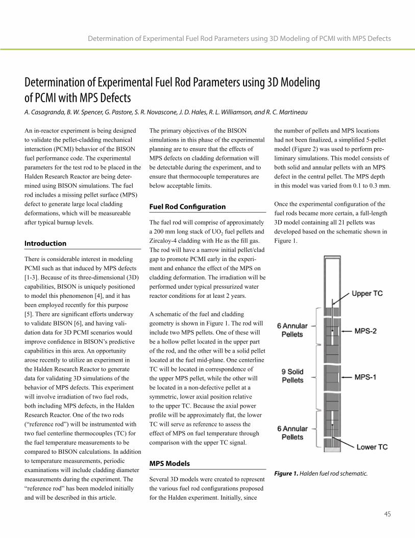
45
Determination of Experimental Fuel Rod Parameters using 3D Modeling of PCMI with MPS Defects
Determination of Experimental Fuel Rod Parameters using 3D Modeling
of PCMI with MPS DefectsA. Casagranda, B. W. Spencer, G. Pastore, S. R. Novascone, J. D. Hales, R. L. Williamson, and R. C. Martineau
An in-reactor experiment is being designed to validate the pellet-cladding mechanical interaction (PCMI) behavior of the BISON fuel performance code. The experimental parameters for the test rod to be placed in the Halden Research Reactor are being deter-mined using BISON simulations. The fuel rod includes a missing pellet surface (MPS) defect to generate large local cladding deformations, which will be measureable after typical burnup levels.
Introduction
There is considerable interest in modeling PCMI such as that induced by MPS defects [1-3]. Because of its three-dimensional (3D) capabilities, BISON is uniquely positioned to model this phenomenon [4], and it has been employed recently for this purpose
to validate BISON [6], and having vali-dation data for 3D PCMI scenarios would
capabilities in this area. An opportunity arose recently to utilize an experiment in the Halden Research Reactor to generate data for validating 3D simulations of the behavior of MPS defects. This experiment will involve irradiation of two fuel rods, both including MPS defects, in the Halden Research Reactor. One of the two rods
two fuel centerline thermocouples (TC) for the fuel temperature measurements to be compared to BISON calculations. In addition to temperature measurements, periodic examinations will include cladding diameter measurements during the experiment. The
and will be described in this article.
The primary objectives of the BISON simulations in this phase of the experimental planning are to ensure that the effects of MPS defects on cladding deformation will be detectable during the experiment, and to ensure that thermocouple temperatures are below acceptable limits.
Fuel Rod Configuration
The fuel rod will comprise of approximately a 200 mm long stack of UO2 fuel pellets and
The rod will have a narrow initial pellet/clad gap to promote PCMI early in the experi-ment and enhance the effect of the MPS on cladding deformation. The irradiation will be performed under typical pressurized water reactor conditions for at least 2 years.
A schematic of the fuel and cladding geometry is shown in Figure 1. The rod will include two MPS pellets. One of these will be a hollow pellet located in the upper part of the rod, and the other will be a solid pellet located at the fuel mid-plane. One centerline TC will be located in correspondence of the upper MPS pellet, while the other will be located in a non-defective pellet at a symmetric, lower axial position relative to the upper TC. Because the axial power
TC will serve as reference to assess the effect of MPS on fuel temperature through comparison with the upper TC signal.
MPS Models
Several 3D models were created to represent
for the Halden experiment. Initially, since
the number of pellets and MPS locations
model (Figure 2) was used to perform pre-liminary simulations. This model consists of both solid and annular pellets with an MPS defect in the central pellet. The MPS depth in this model was varied from 0.1 to 0.3 mm.
fuel rods became more certain, a full-length 3D model containing all 21 pellets was developed based on the schematic shown in Figure 1.
Figure 1. Halden fuel rod schematic.

Nuclear Fuels & Materials Spotlight
46
MPS Defect Depth Effect
The effect of MPS depth on cladding defor-mation is a primary concern in determining the fuel rod geometry. Figure 3 shows the radial deformation of the cladding plotted as a function of distance from the bottom of the fuel rod for a series of MPS depths using the
that even with the smallest MPS depth of 0.1 mm, the radial deformation at the end of the 2-year experiment is approximately 20 microns. Since the resolution of the device for measuring cladding displacement is a few microns, the cladding deformation induced by the 0.1 mm MPS defect should be easily detectable at the end of the exper-iment. Such MPS depth is representative of defects of practical interest. However, introducing a deeper MPS defect in one of the two rods in order to provide detectable effects earlier in the experiment and a more extensive database for BISON validation is being considered.
Contact Model Comparison
The contact model used for the pellet-clad-
behavior of a fuel rod simulation. The clad-ding deformation results shown in Figure 3 were calculated using a frictionless contact model for the pellet-cladding interface. For comparison, this interface was also modeled using a glued contact condition, which may be closer to the experimental conditions, but is still an approximation. The glued contact is enforced as soon as initial contact occurs and the interfaces are not allowed to move tangentially or separate under tension. During the intermittent measurements of the cladding deformation, some fuel-cladding separation may occur, which will not be accounted for using this contact model.
The differences in the local effects caused by different contact models can be seen in Fig-
effective cladding creep strain in the central MPS defect area. The glued model shows higher local strains near the defect, whereas
the frictionless model allows the deformation to be distributed along the cladding and is less localized. In addition, the plot shows the strain varies in the circumferential direction and highlights the necessity for 3D models to capture the effects of MPS defects.
Figure 3. Radial cladding deformation with MPS depth variation.
Figure 2. Five-pellet BISON MPS defect model.
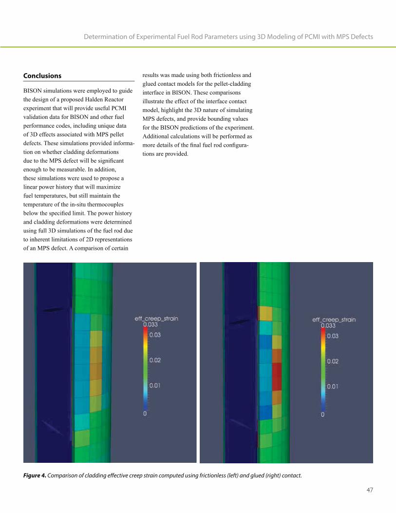
47
Determination of Experimental Fuel Rod Parameters using 3D Modeling of PCMI with MPS Defects
Conclusions
BISON simulations were employed to guide the design of a proposed Halden Reactor experiment that will provide useful PCMI validation data for BISON and other fuel performance codes, including unique data of 3D effects associated with MPS pellet defects. These simulations provided informa-tion on whether cladding deformations
enough to be measurable. In addition, these simulations were used to propose a linear power history that will maximize fuel temperatures, but still maintain the temperature of the in-situ thermocouples
and cladding deformations were determined using full 3D simulations of the fuel rod due to inherent limitations of 2D representations of an MPS defect. A comparison of certain
Figure 4. Comparison of cladding effective creep strain computed using frictionless (left) and glued (right) contact.
results was made using both frictionless and glued contact models for the pellet-cladding interface in BISON. These comparisons illustrate the effect of the interface contact model, highlight the 3D nature of simulating MPS defects, and provide bounding values for the BISON predictions of the experiment. Additional calculations will be performed as
-tions are provided.

Nuclear Fuels & Materials Spotlight
48
References
1. G. Khvostov, W. Lyon, and M. A.
FALCON code to PCI induced cladding failure and the effects of missing pellet
Annals of Nuclear Energy, 62, pp. 398–412.
2. Y. Aleshin, C. Beard, G. Mangham, D. Mitchell, E. Malek, and M. Young,
Proceedings of Top Fuel, 2010, Orlando, Florida, September 26 through 29, 2010.
3. J. S. Lee, J. S. Yoo, H. K. Kim, D.
mechanical behavior of pellet-cladding with the missing chip under PCMI
2007 International LWR Fuel Performance Meeting – TopFuel, San Francisco, Cali-fornia, September 30 through October 3, 2007.
4. R. L. Williamson, J. D. Hales, S. R. Novascone, M. R. Tonks, D. R. Gaston, C. J. Permann, D. Andrs, and R. C.
multiphysics simulation of nuclear fuel Journal of Nuclear Materials,
423, pp. 149–163.
5. B. W. Spencer, R. L. Williamson, D. S. Stafford, S. R. Novascone, J. D. Hales,
Missing Pellet Surface Defects in BWR Nuclear Engineering and Design,
accepted.
6. R. L. Williamson, K. A. Gamble, D. M. Perez, S. R. Novascone, G. Pastore, R. J. Gardner, J. D. Hales, W. Liu, and
fuel performance code to integral LWR Nuclear Engineering and
Design, 301, pp. 232–244.
Al Casagranda
Al Casagranda, Ph.D., is a computational scientist in the Fuel Modeling and Simula-tion Department at INL. He has degrees in Nuclear Engineering from Purdue University (B.S. – 1986, M.S. – 1988) and Materials Science from the University of California at Santa Barbara (Ph.D. – 1993). He has used
including powder metallurgy, metal forming, tire analysis and ASME Section III code applications. Since joining INL in 2015, he has worked as a developer on the BISON fuel performance code.
Benjamin Spencer
Benjamin Spencer (Ph.D. in civil engi-neering from the University of Colorado) is a computational scientist in the Fuel Modeling and Simulation Department at INL. In this capacity, he leads development of the Grizzly code for nuclear power plant component aging and also contributes to the BISON nuclear fuel performance code and to the MOOSE simulation framework, on which these codes are based. Dr. Spencer has been at INL nearly 5 years. Prior to INL, he spent 9 years at Sandia National Laboratories, where he worked as a software developer on solid mechanics applications in the SIERRA code suite and as a structural analyst for nuclear safety applications. He has broad experience in development of
software and application of such software to mechanics and coupled physics problems for nuclear, civil, and mechanical engineering applications.

49
Determination of Experimental Fuel Rod Parameters using 3D Modeling of PCMI with MPS Defects
Giovanni Pastore
Giovanni Pastore, Ph.D., is a research and development scientist in the Fuel Modeling and Simulation Department at INL. Dr. Pastore’s degrees are in Nuclear Engineering (M.S.c, 2008 and Ph.D. cum laude 2012) from Politecnico di Milano (Italy). He has 8 years of experience in nuclear fuel modeling and simulation. Before joining INL, he worked at JRC-ITU (European Commission,
gas behavior model applied to engineering fuel modeling codes. He also has worked at the Halden Reactor Project (Norway), where he contributed to design of an experiment investigating missing pellet surface effects in nuclear fuel rods. His role at INL is developer of the nuclear fuel analysis code
and on fuel rod behavior during LOCAs.
Stephen R. Novascone
Stephen Novascone, Ph.D., is a computa-tional scientist at INL working in the Fuels Modeling and Simulation Department. Stephen has over 17 years of experience working on a variety of engineering research projects. After a brief time at Thiokol, Stephen has spent most of his career at INL. His degrees are in mechanical engineering from Utah State University (B.S. - 1996, M.S. - 1998) and the University of Idaho (Ph. D. - 2003). Since 2010, he’s worked as a developer for BISON, INL’s nuclear fuel performance code. His role on the BISON team is to develop simulation capability, verify and validate BISON, provide training and technical support for BISON users, and publish works regarding BISON applica-tions.
Jason Hales
Jason Hales (Ph.D. from the University of Illinois at Urbana-Champaign) manages the Fuel Modeling and Simulation Depart-ment at INL. The department develops understanding of nuclear material behavior through computational science. Dr. Hales’ research is directed to parallel, nonlinear, fully coupled multi-physics software for internal and external customers. He is a core contributor to BISON, with a principal focus on non-linear solid mechanics development. Before joining INL, Dr. Hales spent 9 years at Sandia National Laboratories, where he worked on solid mechanics applications in SIERRA. His technical skills include numer-ical methods, high-performance computing, non-linear solid mechanics, material model
multiphysics coupling.

Nuclear Fuels & Materials Spotlight
50
Richard Williamson
Richard Williamson, Ph.D., leads the BISON development team within the Fuel Modeling and Simulation Department at INL. He has over 38 of years experience in computational methods research and model development. His current research relates to developing models to simulate nuclear fuel behavior
-physics and multi-dimensional phenomena. Dr. Williamson has over 50 peer-reviewed journal articles and many hundreds of cita-tions to his work. He received his Ph.D. in Mechanical Engineering from the University of Idaho in 1989.
Richard Martineau
Richard Martineau, Ph.D., began employ-ment at INL in July 1989. He is the Director of Nuclear Science and Technology’s Modeling and Simulation and is responsible for those aspects of leading the development
numerical packages, high-performance computing frameworks, and multiphysics analysis tools for nuclear power applications. Dr. Martineau has 25 years of experience
research and investigations. Expertise
nonlinear coupling methods for multiph-ysics applications, compressible material dynamics (including stress wave phenomena
transfer theory, and thermodynamics. Dr. Martineau is the primary developer of the MOOSE-based application called Bighorn, which is designed to simulate single and multi-phase conjugate heat transfer domains. He is also the principle investigator for RELAP-7, the next generation nuclear systems analysis code.

51
Determination of Experimental Fuel Rod Parameters using 3D Modeling of PCMI with MPS Defects

52
Modeling of Fuel Rod
Behavior during LOCA Accidents
with the BISON Code

53
Modeling of Fuel Rod Behavior during LOCA Accidents with the BISON Code
Modeling of Fuel Rod Behavior during LOCA Accidents with the BISON CodeG. Pastore, R. L. Williamson, S. R. Novascone, B. W. Spencer, and J. D. Hales
Idaho National Laboratory’s (INL’s) nuclear fuel performance code, BISON, is being expanded and validated for analysis of nuclear reactor loss-of-coolant-accidents (LOCA). To capture the complex multi-physics behavior of the nuclear fuel rods during LOCAs, new physical models are incorporated into the code. The expanded BISON code is applied to simulation of LOCA experiments and results are compared to experimental data for validation. Further-more, relative to traditional codes, BISON’s added value of being able to model three-di-mensional (3D) effects that importantly affect fuel rod behavior during a LOCA is demonstrated.
Introduction
During a LOCA in a light water reactor (LWR), as occurred at Three Mile Island [1] and Fukushima [2], the fuel rods in the reactor core undergo a temperature transient and give rise to a complex multiphysics response, ultimately, resulting in ballooning and possible failure via burst of the rod clad-ding [3]. Developing computational tools for reliably predicting the thermo-mechanical behavior and lifetime of nuclear fuel rods during LOCA accidents is essential from both safety and economic standpoints [4].
multidimensional nuclear fuel performance code that is under development at INL. Recent advances in BISON include exten-sion of the code to analysis of LWR fuel rod behavior during LOCAs. In this work, we give an account of BISON development and validation for LOCA analysis.
BISON Extensions for Fuel Rod
Modeling During LOCA Accidents
During a LOCA in an LWR, the zircaloy fuel cladding experiences high temperatures while exposed to a low-pressure steam envi-
from the fuel contributes to increasing the rod’s inner pressure. The complex multi-physics response of the cladding involves several mutually coupled physical processes, which leads to ballooning and possible failure via burst [3,4]. To capture the additional physics and increased complexity brought by accident conditions relative to normal reactor operation, dedicated models are incorporated into the BISON code for the main phenomena involved in LWR fuel rod behavior under LOCA conditions.
In particular, models are available in BISON
with gaseous swelling, (2) rapid steam-clad-
ding oxidation, (3) zircaloy solid-solid phase transformation, (4) hydrogen generation and diffusion in zircaloy, (5) zircaloy high-tem-perature non-linear mechanical behavior (i.e., high-temperature creep), and (6) burst failure of zircaloy cladding. Detailed descriptions of these models can be found in [6-8]. This code expansion results in the capability to represent peculiar phenomena occurring during accidents and to consis-tently enclose this additional physics into a global fuel rod analysis.
An example of a 3D BISON calculation for a zircaloy-4 cladding undergoing a repre-sentative LOCA transient [9] is illustrated in Figure 1. Cladding ballooning and burst failure are reproduced by BISON. For this simulation, effects of azimuthal tempera-ture variations in the cladding, which are inherently 3D, are also considered, leading to a consistent representation of non-uniform cladding ballooning and a localized burst on
Figure 1. Contour plots for the BISON 3D simulation of a cladding LOCA test from the REBEKA experiment [9]. The plots are magnified three times in the radial direction for visualization.

Nuclear Fuels & Materials Spotlight
54
the hottest side of the cladding as observed experimentally [9]. This demonstrates the unique capability of BISON to model fuel rod behavior during LOCAs, allowing for
importance because they affect the deforma-tion and failure behavior of the cladding. The implications of the inherently 3D aspects during LOCAs will be further investigated with BISON in the future.
Figure 3. Comparisons between online measurements and BISON predictions of fuel rod inner pressure and time to cladding burst for the Halden IFA-650.2 (left) and IFA-650.10 (right) tests.
Figure 2. Comparisons between BISON predictions and experimental data of cladding burst pressure (left) and time to burst (right) for the MTA-EK separate effects tests PUZRY [10].
BISON Validation Against
LOCA Experiments
In addition to the simulations presented above that demonstrate BISON’s 3D capabil-ities, the expanded code has been validated through comparisons of simulations to experimental data from LOCA experiments. These include both separate effects tests of cladding, ballooning, and burst, as well as integral fuel rod tests performed at the
Halden Research Reactor (Norway).
Comparisons of BISON results to experi-mental data for 31 separate effects tests of zircaloy-4 claddings from [10] are shown in Figure 2. The accuracy of the BISON analyses is in line with the state-of-the-art [11]. Examples of BISON validation results against integral fuel rod LOCA experiments are shown in Figure 3. In particular, BISON results of inner pin pressure during the

55
Modeling of Fuel Rod Behavior during LOCA Accidents with the BISON Code
LOCA transient for the Halden IFA-650.2 [12] and IFA-650.10 [13] tests are compared to experimental measurements. Calculated and experimentally determined times to burst are also illustrated. Predictions are accurate for both cases. The predicted time to burst is within about 7 seconds of the experimental one for IFA-650.2 and within about 9 seconds of the experimental one for IFA-650.10.
Conclusions
This paper presented recent developments and applications of INL’s fuel performance code, BISON, to the analysis of LWR fuel rod behavior during LOCAs. BISON was expanded to allow for complex and mutually dependent phenomena undergone by the fuel rods during LOCA transients. Then the code was validated against LOCA experiments, with an encouraging predictive accuracy. In addition, the unique capability of BISON to reproduce 3D effects that importantly affect fuel rod behavior during LOCAs was demonstrated.
References
1. D. Okrent and D. Moeller, 1981,
Annual Review of Energy, 6, pp. 43.
2. F. D’Auria, G. Galassi, P. Pla, and M.
The Outline and the Technological Science and Technology
of Nuclear Installations, 2012, 507921.
3. P. Van Uffelen, R. J. M. Konings, C.
G. Cacuci, (ed.), Handbook of Nuclear EngineeringBusiness Media, LLC., New York, New York, USA, pp. 1519–1627.
4. P. Van Uffelen, C. Gyori, A. Schubert, J. van de Larr, Z. Hozer, and G. Spykman,
of a Fuel Performance Code from Nor-mal Operating to Design Basis Accident
J. Nucl. Mater, 383, pp. 137.
5. R. L. Williamson, J. D. Hales, S. R. Novascone, M. R. Tonks, D. R. Gaston, C. J. Permann, D. Andrs, and R. C.
Multiphysics Simulation of Nuclear J. Nucl. Mater, 423, pp.
149-163.
6. G. Pastore, S. R. Novascone, R. L. Williamson, J. D. Hales, B. W. Spencer,
Fuel Behavior during Loss-of-Coolant
proceedings Reactor Fuel Performance Meeting, Zurich, Switzerland, Septem-ber 13 through 17, 2015.
7. G. Pastore, R. L. Williamson, S. R. Novascone, B. W. Spencer, and J. D.
Tests with the BISON Fuel Performance Enlarged Halden
Programme Group Meeting, Fornebu, Norway, May 8 through 13, 2016.
8. G. Pastore, D. Pizzocri, J. D. Hales, S. R. Novascone, D. M. Perez, B. W. Spencer, R. L. Williamson, P. Van
of Transient Fission Gas Behaviour in Oxide Fuel and Application to the
Enlarged Halden Programme Group Meeting, Røros, Norway, September 7 through 12, 2014.
9. F. J. Erbacher, H. J. Neitzel, and K. Wiehr, 1990, Tech. Rep. KfK 4781, Kernforschungszentrum Karlsruhe, Germany.
10. E. Perez-Feró, Z. Hózer, T. Novotny, G. Kracz, M. Horváth, I. Nagy, A.
L. Matus, L. Vasáros, P. Windberg, and L. Maróti, 2013, Tech. Rep. EK-FRL-2012-255-01/02, Center for Energy Research, Hungarian Academy of Sciences, Budapest, Hungary.
11. V. Di Marcello, A. Schubert, J. van de
TRANSURANUS Mechanical Model Nucl. Eng.
Des., 276, pp. 19–29.
Tech. Rep. HWR-813, OECD Halden Reactor Project.
Halden; The Tenth Experiment IFA-Tech. Rep. HWR-974, OECD
Halden Reactor Project.

Nuclear Fuels & Materials Spotlight
56
Giovanni Pastore
Giovanni Pastore, Ph.D., is a research and development scientist in the Fuel Modeling and Simulation Department at INL. Dr. Pastore’s degrees are in Nuclear Engineering (M.S.c, 2008 and Ph.D. cum laude 2012) from Politecnico di Milano (Italy). He has 8 years of experience in nuclear fuel modeling and simulation. Before joining INL, he worked at JRC-ITU (European Commission,
gas behavior model applied to engineering fuel modeling codes. He also has worked at the Halden Reactor Project (Norway), where he contributed to design of an experiment investigating missing pellet surface effects in nuclear fuel rods. His role at INL is developer of the nuclear fuel analysis code
and on fuel rod behavior during LOCAs.
Richard Williamson
Richard Williamson, Ph.D., leads the BISON development team within the Fuel Modeling and Simulation Department at INL. He has over 38 years experience in computational methods research and model development. His current research relates to developing models to simulate nuclear fuel behavior
-physics and multidimensional phenomena. Dr. Williamson has over 50 peer-reviewed journal articles and many hundreds of cita-tions to his work. He received his Ph.D. in Mechanical Engineering from the University of Idaho in 1989.
Stephen R. Novascone
Stephen Novascone, Ph.D., is a computa-tional scientist at INL working in the Fuels Modeling and Simulation Department. Stephen has over 17 years of experience working on a variety of engineering research projects. After a brief time at Thiokol, Stephen has spent most of his career at INL. His degrees are in mechanical engineering from Utah State University (B.S. - 1996, M.S. - 1998) and the University of Idaho (Ph. D. - 2003). Since 2010, he’s worked as a developer for BISON, INL’s nuclear fuel performance code. His role on the BISON team is to develop simulation capability, verify and validate BISON, provide training and technical support for BISON users, and publish works regarding BISON applica-tions.

57
Modeling of Fuel Rod Behavior during LOCA Accidents with the BISON Code
Benjamin Spencer
Benjamin Spencer (Ph.D. in civil engi-neering from the University of Colorado) is a computational scientist in the Fuel Modeling and Simulation Department at INL. In this capacity, he leads development of the Grizzly code for nuclear power plant component aging and also contributes to the BISON nuclear fuel performance code and to the MOOSE simulation framework, on which these codes are based. Dr. Spencer has been at INL nearly 5 years. Prior to INL, he spent 9 years at Sandia National Laboratories, where he worked as a software developer on solid mechanics applications in the SIERRA code suite and as a structural analyst for nuclear safety applications. He has broad experience in development of
software and application of such software to mechanics and coupled physics problems for nuclear, civil, and mechanical engineering applications.
Jason Hales
Jason Hales (Ph.D. from the University of Illinois at Urbana-Champaign) manages the Fuel Modeling and Simulation Depart-ment at INL. The department develops understanding of nuclear material behavior through computational science. Dr. Hales’ research is directed to parallel, nonlinear, fully coupled multi-physics software for internal and external customers. He is a core contributor to BISON, with a principal focus on non-linear solid mechanics development. Before joining INL, Dr. Hales spent 9 years at Sandia National Laboratories, where he worked on solid mechanics applications in SIERRA. His technical skills include numer-ical methods, high-performance computing, non-linear solid mechanics, material model
multiphysics coupling.

58
LWR Reactivity-Initiated
Accident Modeling in BISON

59
LWR Reactivity-Initiated Accident Modeling in BISON
LWR Reactivity-Initiated Accident Modeling in BISONCharles Folsom (Utah State University), Richard Williamson (Idaho National Laboratory), and Heng Ban (Utah State University)
Introduciton
A reactivity-initiated accident (RIA) is a nuclear reactor event involving a sudden
rapid increase of reactor power and tempera-ture of the fuel, which may lead to failure of the fuel rods. Transient fuel performance codes capable of modeling RIA are being used to analyze compliance with and/or assess new revised safety criteria for the RIA design basis accident [1].
Fuel performance codes for accident modeling have been developed for some time and have shown an ability to reproduce experimental results with some degree of adequacy. However, due to the highly complex nature of accident modeling, many different models and assumptions have been adopted by the various code developers. This is due, in part, to the limited availability of results from each respective experimental program. As a result, this has led to differ-ences between the various fuel performance codes.
In 2009, the Nuclear Energy Agency (NEA)
Fuel Behavior during Reactivity Initiated -
shop, it was recommended that a benchmark (RIA Benchmark Phase-I) between these codes be organized to give a sound basis for their comparison and assessment. This Phase I benchmark used a set of four experiments on highly irradiated fuel rods under different conditions. Results showed a large disparity in many of the thermal and mechanical behaviors, leading to a second phase, launched in early 2014. This phase is designed to compare results of different
to provide a deeper understanding of the differences in modeling of the different codes [2].
The Working Group on Fuel Safety (WGFS) RIA Fuel Codes Benchmark Phase-II con-sists of 15 organizations from 12 countries contributing results from seven different codes. Idaho National Laboratory joined the benchmark mid-2015 to contribute results from the BISON fuel performance code. BISON is capable of solving the fully coupled equations of thermomechanics and species diffusion for one-dimensional (1D)
spherical, two-dimensional (2D) axisym-metric or plane strain, and three-dimensional (3D) geometries, while many of the other codes are only capable of 1.5-dimensional (1.5D) simulations. This benchmark provided an ideal stage to test and compare BISON capabilities for accident modeling against many other codes that are considered state-of-the-art, thus providing feedback on the strengths and areas of improvement needed in BISON.
Figure 1. Benchmark Case 5 model description: (a) detailed specifications of the benchmark model and geometry and (b) BISON geometry and mesh.

Nuclear Fuels & Materials Spotlight
60
Model Description
prepared to prevent (as much as possible) the variability between the applied model among the different institutions and codes. The full
with an increasing degree of complexity; for this paper only, Case 5 will be discussed
for Case 5 are shown in Figure 1a, with the representative BISON mesh and geometry in Figure 1b. To minimize any differences in the model and input assumptions between codes, the thermal and mechanical properties of fresh pressurized water reactor-type fuel rods are used.
Results
A complete compilation of all the results for all cases and codes was compiled by NEA [3], comparing outputs from each partici-pant. This article compares results from the BISON and FRAPTRAN fuel performance codes for Case 5 of the benchmark.
An important parameter to consider when discussing RIA transients is the amount of energy injected into the fuel and the resulting fuel radial average enthalpy. Historically, the U.S. Nuclear Regulatory Commission’s acceptance criterion for reactivity excursions has been based on the maximum radial average fuel enthalpy in the fuel rod [4]. Therefore, for safety considerations, it is necessary to be able to accurately model the fuel radial average enthalpy of the rodlet. The energy injected into the fuel, fuel radial average enthalpy, and power pulse are shown in Figure 2. Good agreement on the radial average enthalpy of the fuel shows that both codes are calculating comparable radial
entire simulation.
Figure 2. Profile comparisons between FRAPTRAN and BISON for the energy injected into the rodlet and fuel radial average enthalpy shown with the simplified 30-ms FWHM power profile. The inset shows the radial average enthalpy over a longer duration.
Figure 3. Temperature profiles at different radial locations on the rodlet. Inset shows the temperature profiles during a smaller temporal scale around the power pulse.

61
LWR Reactivity-Initiated Accident Modeling in BISON
locations in the rodlet are shown in Figure 3. The fuel centerline temperature shows good agreement between the two codes over the entire transient. The fuel surface and cladding surface temperatures deviate slightly between the two codes. Because of the complexity of the problem and the multiphysics simulation
the temperature differences between the two codes. There are large variations between the fuel-to-cladding gap conductance and clad-
the two codes that will account for some of the temperature differences. Also, differences in mechanical models (such as the gap width between the fuel and cladding) have effects on various mechanisms that do affect energy transport.
The hoop strain and corresponding hoop stress at the outer surface of the cladding are shown in Figure 4. During an RIA event, the cladding is forced to expand and conform to the expansion of the fuel; therefore, the cladding undergoes a displacement-controlled problem. The cladding total hoop strain is controlled by the radial expansion of the fuel until separa-tion occurs during cooling. As such, the total hoop strain shows some variation between the codes. They have very similar evolutions, but FRAPTRAN predicts approximately 0.4% more strain than BISON. This variation cor-relates to a difference in the maximum outer radius of 4.209 mm in BISON and 4.219 mm in FRAPTRAN. This is likely due to multiple reasons. First, FRAPTRAN assumes a rigid pellet that cannot yield, while BISON assumes a compliant fuel pellet. Also differences in fuel thermal expansion and plasticity models between codes could result in the variations in calculated strain.
Each code predicted a maximum hoop stress of about 340 MPa and was within 20 MPa of each other. The two codes agree reasonably
well on the stress, except for a short time just after the power pulse (100.06 to 101.0 s). During this time, there is a complicated trade-off between elastic strain and develop-ment of plastic strain. The increase in plastic strain is due to the decrease of the zircaloy yield strength as the temperature increases. The temperature-dependent yield strength capability was added to BISON as a result of participation in this benchmark.
Conclusions
of the RIA benchmark was to compare the results of different simulations on ten
differences in modeling of the concerned phenomena. Idaho National Laboratory was able to participate in this international collaboration and contribute to seven of the ten cases for the benchmark. Even among
-ited considerable scatter among the codes for some of the parameters, in particular
the cladding hoop stress and strain. The difference between the upper and lower values reaches almost 200% (of the mean value) for the clad hoop stress and 75% for the clad hoop strains. There were also large differences in cladding temperatures that can be contributed to the various thermal-hydraulic models in each code. The clad-to-coolant heat transfer of water boiling during fast transients is considered a large source of uncertainty for all codes and is of considerable interest for further research and development. The complete results are compiled in an NEA/CSNI report [3].
In this report, the results for Case 5 of the benchmark have been compared more rigorously with results obtained from the U.S. Nuclear Regulatory Commission using FRAPTRAN. In general, the results compare reasonably well in both thermal and mechanical aspects and differences can likely be explained by variations in thermal, mechanical, and thermal hydraulic models applied in each respective code.
Figure 4. Hoop stress and total hoop strain at the outer surface of the cladding.

Nuclear Fuels & Materials Spotlight
62
References
1. NEA/CSNI/R(2013)7, 2013, "RIA Fuel
OECD.
Initiated Accident (RIA) Fuel Codes Benchmark Phase-II Report - Volume
OECD.
Initiated Accident (RIA) Fuel Codes Benchmark Phase-II Report - Volume 1:
4. U.S. Atomic Energy Commission, 1974,
a Control Rod Ejection Accident for
Guide 1.77.

63
LWR Reactivity-Initiated Accident Modeling in BISON
Charles Folsom
Charles Folsom is a Ph.D. student in the Department of Mechanical and Aerospace Engineering at Utah State University. He received his master’s degree in Mechanical Engineering from Utah State University in 2012. He has worked in several thermo-physical areas, including concentrating solar power receiver design and performance, thermal property measurements of surrogate TRISO fuel compacts, and development of new pyrometry techniques. His Ph.D. research involves multiphysics modeling of nuclear fuel performance for accident tolerant fuel concepts under reactivity-initi-ated accidents.
Richard Williamson
Richard Williamson, Ph.D., leads the BISON development team within the Fuel Modeling and Simulation Department at INL. He has over 38 of years experience in computational methods research and model development. His current research relates to developing models to simulate nuclear fuel behavior
-physics and multi-dimensional phenomena. Dr. Williamson has over 50 peer-reviewed journal articles and many hundreds of cita-tions to his work. He received his Ph.D. in Mechanical Engineering from the University of Idaho in 1989.
Heng Ban
Heng Ban (Ph.D. 1994, University of Kentucky) is a Professor of Mechanical and Aerospace Engineering at Utah State University. He is the founding Director of Thermohydraulics and Materials Properties Center and lead the research and education effort at Utah State University. His research focuses on thermophysical properties of nuclear materials, especially the effect of irradiation on thermal conductivity, and development of measurement technologies for laboratory, hot cell and in pile appli-cations. Ban has won many teaching and student advising awards, and is known to be innovative in integrating research and educa-tion. Ban is active in service to professional societies, especially the thermophysical property research community. He organized international conferences and provided leadership in professional committees.

64
Validating the BISON Fuel
Performance Code to Integral
LWR Experiments

65
Validating the BISON Fuel Performance Code to Integral LWR Experiments
Validating the BISON Fuel Performance Code to Integral LWR ExperimentsR. L. Williamson, K. A. Gamble, D. M. Perez, S. R. Novascone, G. Pastore, R. J. Gardner, and J. D. Hales
Introduction
nuclear fuel performance code that has been under development at the Idaho National Laboratory since 2009 [1]. The code is applicable to both steady and transient fuel behavior and can be used to analyze one-dimensional (spherically symmetric), two-dimensional (i.e., axisymmetric and generalized plane strain), or three-dimen-sional geometries. BISON has been used to investigate a variety of fuel forms, including light water reactor (LWR) oxide fuel [1], TRISO-coated-particle fuel [2], and metallic fuel in rod and plate form [3, 4]. The code has also been used to investigate novel fuel concepts [5], design and interpret irradiation experiments [6], and investigate fuel defects [7]. BISON is built using the Idaho National Laboratory Multiphysics Object-Oriented Simulation Environment (MOOSE) [8].
modeling, validation efforts are underway. To date, BISON predictions have been compared to roughly 50 integral rod LWR experiments. Comparisons have focused on measurements of fuel centerline temperature,
diameter both before and following fuel-clad mechanical contact, with much of this validation work reported recently [9]. The objective of this article is to provide a brief summary of these comparisons.
Light Water Reactor Validation
Results
A comparison of predicted and measured fuel centerline temperature is shown in Figure 1 for rods in the burnup range of
2
an error range of ±10%. With only a few exceptions, BISON predictions are within this range, which is very reasonable con-sidering measurement uncertainty. Further comparisons in reference [9] demonstrate similar predictive capability for irradiations varying from beginning-of-life through high burnup, including power ramping.
Comparisons of measured versus predicted FGR are shown in Figure 2. BISON’s accuracy in predicting gas release is generally consistent with state-of-the-art modeling practices. Because of the inherent uncertainties of FGR modeling, a deviation
of fuel performance code predictions from the experimental data within a factor of about 2 up and down is generally regarded as satisfactory.
Figure 3 summarizes rod diameter compar-isons in terms of the difference between the measured and predicted values as a function of burnup, with comparisons separated by cladding type (zircaloy-4 and zircaloy-2). Comparisons are made either at the rod axial midplane or averaged over the rod length, based on the available experimental data. In general, the results indicate a tendency to overpredict the diameter reduction that
overpredict the diameter increase that occurs late in life. The early life comparisons typically occur before fuel-clad contact, when clad deformation is dominated by clad creep down; therefore, comparisons indicate a tendency to overpredict clad creep rates.
Figure 1. Comparison of the measured versus predicted fuel centerline temperature for rods in the burnup range of 20≤Bu<40 MWd/kgUO2. The Rf parameter in the IFA-562.2 Rod 17 labels indicate the fuel roughness used in the simulation. M = P stands for measured = predicted. The specific experiments identified in the legend are described in more detail in [9].

Nuclear Fuels & Materials Spotlight
66
Although the number of low burnup points is limited, diameter comparisons indicate this overprediction is more severe for zircaloy-2 than zircaloy-4. Reasons for this overpre-diction could include large variations and uncertainty that exist in clad microstructure and the lack of an anisotropic creep model in BISON. Comparison to separate-effects clad creep experiments are underway to better understand and improve predictions. At higher burnups following fuel-clad contact, clad diameter increase is controlled by the mechanical behavior of the fuel. The fact that the clad diameter change (measured –
a tendency to overpredict fuel radial
diameter may be partially due to its lack of a relocation recovery model, which would recover a portion of the relocation strain upon fuel cladding contact. Uncertainty in
during irradiation provide further possible explanation for poor diameter comparisons. Fuel creep, which has been neglected in the present comparisons, is also expected to play
combined with smeared cracking in BISON is underway.
A more detailed comparison of rod diameter predictions is possible for the Risø-3 GE7 validation case, which includes full-length rod diameter comparisons at both the end of base irradiation and following a power ramp. Recent BISON simulations have included both smeared and discrete pellet geometries, also providing a comparison of the effects of this modeling assumption. Figure 4 compares the predicted and measured rod diameter as a function of rod length. The diameter of the pre-irradiated rod is shown as a solid black line for reference. Diameter measurements following base irradiation are indicated with open circle symbols. Post ramp measurements were made on the
0 10 20 30 40 50 60Rod Average Burnup (MWd/kgU)
-100
-80
-60
-40
-20
0
20
40
60
Cla
d o
ute
r d
ia. (
Mea
s. -
Pre
d.)
(m
)
Zr-4Zr-2
Figure 2. Comparisons of the measured versus predicted fission gas release with a factor of 2 error band. The specific experiments identified in the legend are described in more detail in [9].
Figure 3. The difference between measured and predicted rod diameter as a function of burnup during base irradiation. The specific experiments are described in [9].

67
Validating the BISON Fuel Performance Code to Integral LWR Experiments
cladding adjacent to pellet mid and end loca-
respectively. BISON overpredicts clad creep rates during base irradiation, resulting in a decrease in rod diameter roughly double the measured value. Note that the predicted axial
is predicted to have been in contact with the clad at some time during base irradiation.
-sure history, which indicates contact begins at a burnup of approximately 28 MWd/kgU. On the other hand, the measured diameter
evidence of contact, which is not surprising based on the much lower measured clad creep down. Comparing the measured and predicted diameter change during the ramp test indicates BISON does a reasonable job of predicting the transient mechanical behav-
ior. Permanent change in the clad diameter results from both creep and instantaneous plasticity and is driven principally by ther-mal expansion and gaseous swelling of the
for the discrete pellet simulation are due to the predicted hour-glassing of individual fuel pellets, which were clearly in contact with the cladding during the power ramp. For this experiment, overall comparison of the post ramp diameter to measurements improves when considering individual pellets over smeared fuel. However, it is also clear that the predicted ridge magnitude is larger than measured. This overprediction in ridging is believed to be principally due to the assumption of elastic fuel, because fuel creep would naturally reduce peaks at pellet ends. The effect of fuel creep on ridging will be isolated in a future study.
Figure 4. Comparison of the computed and measured rod diameter as a function of rod length for the Risø-3 GE7 experiment.
Conclusions
BISON predictions of fuel centerline tem-
outer diameter have recently been compared to roughly 50 integral rod LWR experiments. Results demonstrate the following:
• Fuel centerline temperature comparisons through all phases of fuel life are very reasonable. Deviations between predic-tions and experimental data are shown to be within ±10%.
• Accuracy in predicting FGR appears to be consistent with state-of-the-art model-ing and with involved uncertainties.
• Comparison of rod diameter results indicate a tendency to overpredict clad diameter reduction early in life, when clad creep down dominates and, more
increase late in life, when fuel expansion controls the mechanical response.
Results from this study are being used to de-
and validation activities. High priority items include the following:
• An increased emphasis on separate effects validation experiments, especially for fuel swelling and fuel and cladding creep
• Inclusion of more realistic mechani-
smeared cracking and creep
• Addition of a relocation recovery model
• Consideration of discrete pellet geometry in validation cases, especially for clad-ding diameter comparisons
• Expansion of the validation base to include other fuel types, including MOX and Gd-doped fuels
• Inclusion of the effects of high burnup structure on fuel performance

Nuclear Fuels & Materials Spotlight
68
• Addition of accident behavior cases (both loss-of-coolant-accident and reac-tivity-initiated accident) to the validation base.
References
1. R. L. Williamson, J. D. Hales, S. R. Novascone, M. R. Tonks, D. R. Gaston, C. J. Permann, D. Andrs, and R. C.
multiphysics simulation of nuclear fuel J. Nucl. Mater., 423, pp.
149–163.
2. J. D. Hales, R. L. Williamson, S. R. Novascone, D. M. Perez, B. W. Spencer,
multiphysics simulation of TRISO J. Nucl. Mater., 443, pp.
531–543.
modeling results for representative FCRD irradiation experiments: Projected deformation in the annular AFC-3A U-10Zr fuel pins and compar-
report INL/EXT-12-27183, Revision 1, Idaho National Laboratory.
4. N. N. Carlson, C. Unal, and J. D.
constituent distribution model imple-mented into the BISON framework for the analysis of performance of metallic fuels with some initial simulation
26824, Los Alamos National Laboratory.
5. K. E. Metzger, T. W. Knight, and R. L. U3Si2 fuel
Pro-ceedings of the International Congress on Advances in Nuclear Power Plants - ICAPP 2014, Charlotte, North Carolina, April 6 through 9, 2014.
6. A. Casagranda, B. W. Spencer, G. Pas-tore, S. R. Novascone, J. D. Hales, R. L. Williamson, and R. C. Martineau, 2016,
Parameters using 3D Modeling of PCMI PCMI Workshop,
Lucca, Italy, June 15 through 17, 2016.
7. B. Spencer, R. Williamson, D. Stafford, S. Novascone, J. Hales, and G. Pastore,
Nuc. Eng. Design, 307, pp. 155-171.
8. D. Gaston, C. Newman, G. Hansen, and
A parallel computational framework for coupled systems of nonlinear
Nuc. Eng. Design, 239, pp. 1768–1778.
9. R. L. Williamson, K. A. Gamble, D. M. Perez, S. R. Novascone, G. Pastore, R. J. Gardner, J. D. Hales, W. Liu, and
fuel performance code to integral LWR Nuc. Eng. Design, 301,
pp. 232–244.

69
Validating the BISON Fuel Performance Code to Integral LWR Experiments
Kyle Gamble
Kyle Gamble (Ph.D. student at the Univer-sity of South Carolina) is a computational scientist in the Fuel Modeling and Simu-lation Department at INL, where he is a developer of the BISON fuel performance code. His primary focus is on material model
and validation. Prior to joining INL, Mr. Gamble was completing his Master’s degree at the Royal Military College of Canada in collaboration with the Canadian Nuclear Laboratories. His technical skills include fuel performance, material model develop-ment, multiphysics coupling, and uncertainty
Richard Williamson
Richard Williamson, Ph.D., leads the BISON development team within the Fuel Modeling and Simulation Department at INL. He has over 38 of years experience in computational methods research and model development. His current research relates to developing models to simulate nuclear fuel behavior
-physics and multi-dimensional phenomena. Dr. Williamson has over 50 peer-reviewed journal articles and many hundreds of cita-tions to his work. He received his Ph.D. in Mechanical Engineering from the University of Idaho in 1989.
Danielle Perez
Danielle Perez received her B.S. in Nuclear Engineering from Idaho State University. Perez started working at INL as an intern in 2006 and was hired on full time in June 2010. Starting in 2009 she spent 3 years working on nuclear fuel performance analysis for the Reduced Enrichment for Research and Test Reactor Program. In November 2011, she began working on the assessment effort for BISON. She is also currently working toward her M.S. degree in Mechanical Engineering at Idaho State University. In addition, she served on the executive committee of the Idaho section of the American Nuclear Society for the past 6 years. In 2012, she served as the section chairman.

Nuclear Fuels & Materials Spotlight
70
Giovanni Pastore
Giovanni Pastore, Ph.D., is a research and development scientist in the Fuel Modeling and Simulation Department at INL. Dr. Pastore’s degrees are in Nuclear Engineering (M.S.c, 2008 and Ph.D. cum laude 2012) from Politecnico di Milano (Italy). He has 8 years of experience in nuclear fuel modeling and simulation. Before joining INL, he worked at JRC-ITU (European Commission,
gas behavior model applied to engineering fuel modeling codes. He also has worked at the Halden Reactor Project (Norway), where he contributed to design of an experiment investigating missing pellet surface effects in nuclear fuel rods. His role at INL is developer of the nuclear fuel analysis code
and on fuel rod behavior during LOCAs.
Stephen R. Novascone
Stephen Novascone, Ph.D., is a computa-tional scientist at INL working in the Fuels Modeling and Simulation Department. Stephen has over 17 years of experience working on a variety of engineering research projects. After a brief time at Thiokol, Stephen has spent most of his career at INL. His degrees are in mechanical engineering from Utah State University (B.S. - 1996, M.S. - 1998) and the University of Idaho (Ph. D. - 2003). Since 2010, he’s worked as a developer for BISON, INL’s nuclear fuel performance code. His role on the BISON team is to develop simulation capability, verify and validate BISON, provide training and technical support for BISON users, and publish works regarding BISON applica-tions.
Russell Gardner
Russell Gardner received his Bachelor of Science Degree in Nuclear Engineering from Oregon State University in 2010 and is a current graduate student in mechanical engineering at the University of Idaho. He started working at INL as an intern in 2009 and became a full-time employee in early 2010, working in nuclear operations at INL’s Advanced Test Reactor (ATR). Mr. Gardner spent 4 years at ATR, where he participated in many different evolutions such as fuel handling, water chemistry controls, and experiment handling. Russell joined the BISON team in 2014 working on code vali-
results against experiment measurements. Along with the continuing BISON validation efforts, he also helps with user support, training, and BISON development.

71
Validating the BISON Fuel Performance Code to Integral LWR Experiments
Jason Hales
Jason Hales (Ph.D. from the University of Illinois at Urbana-Champaign) manages the Fuel Modeling and Simulation Depart-ment at INL. The department develops understanding of nuclear material behavior through computational science. Dr. Hales’ research is directed to parallel, nonlinear, fully coupled multi-physics software for internal and external customers. He is a core contributor to BISON, with a principal focus on non-linear solid mechanics development. Before joining INL, Dr. Hales spent 9 years at Sandia National Laboratories, where he worked on solid mechanics applications in SIERRA. His technical skills include numer-ical methods, high-performance computing, non-linear solid mechanics, material model
multiphysics coupling.

72
MARMOT Modeling of
Thermal Conductivity of High Burnup
Structure in UO2 Fuels

73
MARMOT Modeling of Thermal Conductivity of High Burnup Structure in UO2 Fuels
MARMOT Modeling of Thermal Conductivity of High Burnup Structure in UO2 FuelsXianming Bai, Michael R. Tonks, Yongfeng Zhang, and Jason D. Hales
Abstract
High-burnup structure (HBS) is a self-or-ganized microstructure formed at the rim region in UO2 fuels with many interesting physical properties. Although the HBS con-tains a high density of grain boundaries, its thermal conductivity increases with respect to its larger-grain counterpart. MARMOT modeling was used to investigate this inter-esting problem. The results indicated that both the atomistic and mesoscale thermal transport mechanisms must be considered to understand this interesting phenomenon.
The harsh irradiation received by uranium dioxide (UO2) fuels in reactors causes complex microstructural evolution in fuels. One of the fuel restructuring phenomena is
the formation of HBS near the fuel pellet rim region [1]. Before HBS forms, the fuel grain size is about 10 microns and the fuel contains some small pores from the fuel fabrication (Figure 1[a]). After the HBS forms, the grain size decreases to about 0.1–0.3 microns through a grain subdivision process, during which many micron-size pores or bubbles form. Therefore, HBS has a microstructure of small grains and big bubbles, as shown Figure 1[b]. Because HBS has a very different microstructure from that at low burnup, the physical properties of HBS such as thermal conductivity also change. Intuitively, the thermal conductivity of HBS should be lower than that of the unrestructured microstructure because con-tains high-density grain boundaries (GBs).
Interestingly, experiments [2, 3] have shown that the reduction of thermal conductivity of nuclear fuels with increasing burnup actually is slowed down upon HBS formation (Figure 1[c]), which is counterintuitive. To under-stand this interesting phenomenon, we used the MARMOT mesoscale fuel performance tool [4] developed at Idaho National Labo-ratory to model the thermal conductivity of HBS. Detailed information of this work can be found in Bai et al.’s article [5].
with heat conduction in MARMOT was used to calculate the effective thermal conductivity of various fuel microstructures. Three micro-structures were modeled: large Xe bubbles in small grains, random small bubbles in large grains, and GB-aligned small bubbles in large
HBS, the second and third microstructures represent intragranular and intergranular bubbles in unrestructured fuels, respectively. The effective thermal conductivities of the three microstructures were calculated for different bubble porosities at 300 K (Figure 2). As expected, the thermal conductivities in all three systems decrease monotonically with increasing bubble porosity (p). However, over the entire porosity range studied in this work, the HBS has a lower thermal conductivity than that of the unrestructured microstructure with random bubbles. These results contradict the experimental observation that the local thermal conductivity of the HBS region increases upon its formation with respect to the unrestructured fuel at the same porosity (Figure 1[c]). Therefore, simply considering the topology of large microstructural features
thermal transport properties observed in experiments.
Figure 1. (a – b) Scanning electron microscopy (SEM) images of microstructures from fresh fuel and after HBS forms [1]. (c) Thermal diffusivity of UO2 fuels as a function of the fuel burnup. [3].

Nuclear Fuels & Materials Spotlight
74
induces not only many experimentally observable microstructures such as dislo-cation loops and bubbles, but also many small point defects (interstitials, vacancies, dispersed Xe gas atoms, etc.) and defect clusters. These small defects can cause
strong phonon scattering effects on thermal transport: therefore, these defects should not be neglected. Recently, molecular dynamics (MD) simulations were conducted to study the degradation of thermal conductivity at different Xe concentration and temperatures [6]. This atomistic information has been
implemented into a new model in MAR-MOT. It is well known that GBs are defect sinks so that point defects can be effectively removed from the grain interior when the grain size is small [7]. Therefore, in our mesoscale modeling, we assumed that in HBS there were no dispersed Xe atoms in the grain interior due to GB-Xe interaction (i.e., all Xe atoms form bubbles). While in the large-grain microstructure, both Xe bub-bles and dispersed Xe atoms were present.
Using the new model, we recalculated the thermal conductivity of a HBS and a large-grain UO2 with randomly distributed bubbles and dispersed Xe atoms as a function of the Xe bubble porosity at 300 K. When there were no dispersed Xe atoms present in both systems, the HBS had a lower thermal conductivity than the large-grain system over the entire range of bubble porosity, which is shown in Figure 2. However, once a small concentration of dispersed Xe was added to the grain interior of the large-grain system, the trend was reversed. As Figure 3 shows, the large-grain system had a lower thermal conductivity than the HBS even if only 0.1% of dispersed Xe atoms were included. As the concentration of dispersed Xe atoms increased, the thermal conductivity of the large-grain system decreased further. In HBS, the GB-Xe interaction made the grain interior free of dispersed-Xe-induced phonon scattering effects. As a result, in HBS the decreased thermal conductivity caused by GBs was compensated by the suppression of phonon scattering effects induced by point defects. Therefore, although GBs them-selves impeded the thermal transport, their interaction with point defects improved the overall thermal conductivity. This GB-defect interaction could be a reasonable explanation for why thermal conductivity of the HBS increased with respect to the unrestructured fuels (Figure 1[c]).
Figure 2. MARMOT results of the thermal conductivities of three microstructures as a function of bubble porosity at 300 K. In the insets, blue circles represent Xe bubbles, yellow lines represent GBs, and red areas represent UO2 matrix.
Figure 3. The thermal conductivity as a function of Xe bubble porosity in a HBS and in a large-grain UO2 with randomly distributed bubbles at different dispersed Xe concentration at 300 K. Symbols: MARMOT calculation results; Lines: Analytical model predictions.
75
MARMOT Modeling of Thermal Conductivity of High Burnup Structure in UO2 Fuels
We also developed an analytical model that can quantitatively predict the thermal conductivity of different microstructures (including HBS) at any given concentration of dispersed Xe, bubble porosity, and grain size. Similar to a previous model [8], the effective thermal conductivity of a heteroge-neous system is described by the multiplier of the degradation percentage caused by each type of microstructural feature. In Figure 3, only the data set of 0% Xe was used to calibrate this analytical model. Once the model was calibrated, all parameters remained unchanged. Figure 7 shows the comparison between the model prediction (solid lines) and the MARMOT simulation results (symbols). While the top-most data set is used for calibration, the model pre-diction was independent of the MARMOT simulation results for all other data sets. Clearly, excellent agreement between them can be seen for a wide range of microstruc-tural parameters. Therefore, the model is very robust and has a predictive power for
We concluded that considering the topol-ogy of large microstructures alone is not
properties in nuclear fuels. The phonon scattering effects caused by small point defects, such as dispersed Xe atoms, must be included in the mesoscale modeling. In extreme cases, even a small concentration of dispersed Xe atoms (e.g., 10-5) can result in a lower thermal conductivity in the large-grain unrestructured microstructures than in the small-grain HBS. The high-density GBs in HBS act as defect sinks and can reduce the concentration of point defects in its grain interior. As a result, its thermal conductivity increases in comparison with its large-grain counterparts. An analytical model was developed to describe the thermal conduc-tivity at different concentrations of dispersed Xe, bubble porosities, and grain sizes. Upon
calibration, the model agrees well with independent heat conduction modeling over a wide range of microstructural parameters.
References
1. V. V. Rondinella, and T. Wiss, 2010, "The high burn-up structure in nuclear fuel," Materials Today, 13, pp. 24–32.
2. C. Ronchi, M. Sheindlin, D. Staicu, and M. Kinoshita, 2004, "Effect of burn-up on the thermal conductivity of uranium dioxide up to 100.000 MWdt-1," Journal of Nuclear Materials, 327, pp. 58–76.
3. C. T. Walker, D. Staicu, M. Sheindlin, D. Papaioannou, W. Goll, and F. Sontheimer, 2006, "On the thermal con-ductivity of UO2 nuclear fuel at a high burn-up of around 100MWd/kgHM," Journal of Nuclear Materials, 350, pp. 19–39.
4. M. R. Tonks, D. Gaston, P. C. Millett, D. Andrs, and P. Talbot, 2012, "An
-
simulations," Computational Materials Science, 51, pp. 20–29.
5. X.-M. Bai, M. R. Tonks, Y. Zhang, and J. D. Hales, 2016, "Multiscale modeling of thermal conductivity of high burnup structures in UO2 fuels," Journal of Nuclear Materials, 470, pp. 208–215.
6. M. R. Tonks, X.-Y. Liu, D. Andersson, D. Perez, A. Chernatynskiy, G. Pastore, C. R. Stanek, and R. Williamson, 2016, "Development of a multiscale thermal
UO2," Journal of Nuclear Materials, 469, pp. 89–98.
7. X.-M. Bai, A. F. Voter, R. G. Hoagland, M. Nastasi, and B. P. Uberuaga, 2010,
Damage Near Grain Boundaries via Interstitial Emission," Science, 327, pp. 1631–1634.
8. P. C. Millett, D. Wolf, T. Desai, S. Rokkam, and A. El-Azab,2008, "Phase-
in porous polycrystalline microstruc-tures," Journal of Applied Physics, 104, 033512.

Nuclear Fuels & Materials Spotlight
76
Michael R. Tonks
Michael Tonks, (Ph.D. in mechanical engi-neering from the University of Illinois), is an Assistant Professor from the Department of Mechanical and Nuclear Engineering at Pennsylvania State University. Prior to coming to Penn State in the fall 2015, he worked at INL for 7 years. During his time at INL, he lead development of MARMOT, (a mesoscale fuel performance code). He also was the Computational Microstructure Science Group lead in the Fuels Modeling and Simulation Department at INL. Dr. Tonks is a computational materials sci-entist that investigates the coevolution of microstructure and properties in materials under harsh environments. He received the American Nuncler Society Materials Science and Technology Division Special Achieve-ment Award in 2015, and INL Early Career Exceptional Achievement Award, the U.S. DOE Nuclear Energy Advanced Modeling and Simulation Program Excellence Award, and the TMS Structural Materials Division Young Leader Professional Development Award in 2014.
Xianming (David) Bai
Xianming (David) Bai (Ph.D., 2006, Georgia Institute of Technology; B.S., 1997, Fudan University) is an Assistant Professor of Materials Science and Engineering at Virginia Tech (2016-present), after working for 5 years at INL (2011-2016). His research activities include computer modeling of radiation damage evolution and physical property change in nuclear materials. In particular, he has studied many interesting
oxide fuels, thermal transport in high burnup structures in fuels, radiation-induced precip-itation of metallic clusters and the associated radiation hardening in reactor pressure vessel steels, and oxidation of zirconium alloys.
Yongfeng Zhang
Yongfeng Zhang (Ph.D., 2009, Mechanical Engineering, Rensselaer Polytechnical Institute) is currently a staff scientist at INL. He leads the Computational Micro-structure Science group, which focuses on lower-length scale modeling of in-reactor behaviors of nuclear fuels and materials. He graduated from Rensselaer Polytechnic Institute with a Ph.D. degree in Mechanical Engineering, and joined INL after that. His research interests focus on atomistic to mesoscale modeling and simulation of microstructural evolution and property degradation in nuclear materials, including fuels and structural materials. His research work has led to over 30 peer-reviewed journal publications. He has also served as a
an organizer for several conference sympo-siums.
77
MARMOT Modeling of Thermal Conductivity of High Burnup Structure in UO2 Fuels
Jason Hales
Jason Hales (Ph.D. from the University of Illinois at Urbana-Champaign) manages the Fuel Modeling and Simulation Depart-ment at INL. The department develops understanding of nuclear material behavior through computational science. Dr. Hales’ research is directed to parallel, nonlinear, fully coupled multi-physics software for internal and external customers. He is a core contributor to BISON, with a principal focus on non-linear solid mechanics development. Before joining INL, Dr. Hales spent 9 years at Sandia National Laboratories, where he worked on solid mechanics applications in SIERRA. His technical skills include numer-ical methods, high-performance computing, non-linear solid mechanics, material model
multiphysics coupling.
78
Development of
Phase-Field Models in MARMOT
for U-Zr Fuel
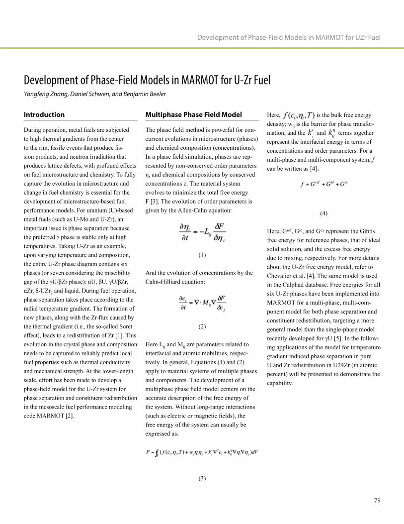
79
Development of Phase-Field Models in MARMOT for UZr Fuel
Development of Phase-Field Models in MARMOT for U-Zr FuelYongfeng Zhang, Daniel Schwen, and Benjamin Beeler
Introduction
During operation, metal fuels are subjected to high thermal gradients from the center
-sion products, and neutron irradiation that produces lattice defects, with profound effects on fuel microstructure and chemistry. To fully capture the evolution in microstructure and change in fuel chemistry is essential for the development of microstructure-based fuel performance models. For uranium (U)-based metal fuels (such as U-Mo and U-Zr), an important issue is phase separation because
temperatures. Taking U-Zr as an example, upon varying temperature and composition, the entire U-Zr phase diagram contains six phases (or seven considering the miscibility
2 and liquid. During fuel operation, phase separation takes place according to the radial temperature gradient. The formation of
the thermal gradient (i.e., the so-called Soret effect), leads to a redistribution of Zr [1]. This evolution in the crystal phase and composition needs to be captured to reliably predict local fuel properties such as thermal conductivity and mechanical strength. At the lower-length scale, effort has been made to develop a
phase separation and constituent redistribution in the mesoscale fuel performance modeling code MARMOT [2].
Multiphase Phase Field Model
-current evolutions in microstructure (phases) and chemical composition (concentrations).
-resented by non-conserved order parameters
concentrations c. The material system evolves to minimize the total free energy F [3]. The evolution of order parameters is given by the Allen-Cahn equation:
(1)
And the evolution of concentrations by the Cahn-Hilliard equation:
(2)
Here Lij and Mij are parameters related to interfacial and atomic mobilities, respec-tively. In general, Equations (1) and (2) apply to material systems of multiple phases and components. The development of a
accurate description of the free energy of the system. Without long-range interactions
free energy of the system can usually be expressed as:
(3)
Here, is the bulk free energy density; wij is the barrier for phase transfor-mation; and the k
i
c and kij terms together represent the interfacial energy in terms of concentrations and order parameters. For a multi-phase and multi-component system, f can be written as [4]:
(4)
Here, Gref, Gid, and Gex represent the Gibbs free energy for reference phases, that of ideal solid solution, and the excess free energy due to mixing, respectively. For more details about the U-Zr free energy model, refer to Chevalier et al. [4]. The same model is used in the Calphad database. Free energies for all six U-Zr phases have been implemented into MARMOT for a multi-phase, multi-com-ponent model for both phase separation and constituent redistribution, targeting a more general model than the single-phase model
-ing applications of the model for temperature gradient induced phase separation in pure U and Zr redistribution in U24Zr (in atomic percent) will be presented to demonstrate the capability.

Nuclear Fuels & Materials Spotlight
80
Phase Transformation Induced by a
Temperature Gradient
For temperature gradient induced phase separation, a quasi-1D simulation cell with x = 1,000 and y = 10 (Figure 1) was used. The Zr concentration was set to be 0.0 to
(K). Phases that were preferred at the corre-sponding temperature regions were observed
until the system was equilibrated. At the equilibrium state, the stable phases were
region from 573 K to 950.3 K (677.3°C),
1405.0 K (1132.0°C), and the liquid phase when T > 1405.0 K. These results are in good agreement with the Calphad database.
Zr Redistribution in U24Zr
Another test of the model focused on Zr
the temperature gradient in a UZr fuel, a
temperature-dependent mobility taken from the literature [6] was used in the simulation.
cZr = 0.24 uniformly. After simulation
place at the center due to the high local tem-perature, Figures 2(a) and (c). For the high
leading to depletion of Zr in the intermediate region. While at the rim, Zr concentration remained at 24-atomic% due to the low
observed in the simulation is in similar shape
with that observed in a U-Pu-Zr fuel [1], which showed increased CZr in the center, depletion in the middle, and intact CZr at the rim. However, direct comparison may not be
simulation, while it has been characterized
in the experiments. In reality, Zr redistri-bution is caused by the different solubility in different U phases and the Soret effect,
gradient. The phase separation is governed by the temperature-dependent free energy of
Figure 1. Contours of order parameters for αU (η1 = 1), βU (η2 = 1), γU/Zr (η3 = 1) and the liquid phase (η4 = 1) at (a) t = 0 and (b) t = 24,000. In (c) the temperature and order parameter profiles at t = 24,000 along y = 0 are plotted as functions of x. The units are nm in space and second in time.
Figure 2. Profiles of (a) order parameter for γU and (b) Zr concentration along r at various times. (c) and (d) show the order parameter and concentration contours at t = 0 and t = 8000.

81
Development of Phase-Field Models in MARMOT for UZr Fuel
each phase, the interfacial energies and the elastic mismatches between phases. In the simulation shown in Figure 2, no Soret effect was included for the purpose of testing phase separation and its effect on Zr redistribution. It is interesting to observe that in Figure 2, Zr depletion could occur without the Soret effect, in line with that in Nam et al. [7] Zr redistribution is governed by Zr solubility. Still, the contribution of Soret effect (already available in MARMOT) needs to be coupled to predict the boundaries of depletion. Fur-ther development of MARMOT is underway for the capability of modeling constituent redistribution.
Discussions and Conclusion
The above results demonstrate the current MARMOT capability for phase separation and constituent redistribution in U-Zr fuel. More details about the model can be reached in the 2015 report by Gamble et al. [8]. Similar development is underway for U-Mo and U-Si fuels. Since the free energy models are taken from the Calphad database, the models in MARMOT are expected to be ther-modynamically quantitative for bulk phases. However, improvements are needed for better modeling performance. First, to resolve inter-
needed, which strongly limits the size of the
The second improvement needed is on the material properties. In addition to the free energy models for bulk phases, Zr diffusiv-ities and heat of transport in various phases, interfacial energies, and elastic mismatches between phases are also needed for quantita-tive description of dynamic phase evolution. Many of these parameters are yet to be achieved from either experiments or lower length scale modeling approaches. Currently, multiscale modeling and simulation effort are
and to obtain the needed material parameters.
Acknowledgements
The work is supported by the U.S. Depart-ment of Energy Advance Fuel Campaign and Nuclear Energy Advanced Modeling and Simulation Program.
References
1. G. L. Hofman, S. L. Hayes, and M.
driving constituent redistribution in U-Zr Journal of Nuclear Materials,
227, pp. 277–286.
2. M. R. Tonks, D. Gaston, P. C. Millett,
-
Computational Materials Science, 51, pp. 20–29.
Annual Review of Materials Research, 32, pp. 113–40.
4. P. Y. Chevalier, E. Fischer, and B. -
modynamic modelling of the O–U–Zr Computer Coupling of
Phase Diagrams and Thermochemistry, 28, pp. 15–40.
5. R. R. Mohanty, J. Bush, M. A. Okuniewski, and Y. H. Sohn, 2011,
Journal of Nuclear Materials, 414, pp. 211–216.
6. W. Li, R. Hu, Y. W. Cui, H. Zhong, H. -
putational study of atomic mobility for the bcc phase of the U–Pu–Zr ternary
Journal of Nuclear Materials, 407, pp. 220–227.
7. C. Nam and W. Hwang, 1998, Journal of the Korean Nuclear Society, 30, pp. 507–517.
8. K. Gamble, R. Williamson, D. Schwen, Y. Zhang, S. Novascone, and P. Med-vedev, 2015, MARMOT Development for Modeling Fast Reactor Fuel Per-formance, INL/EXT-15-36440, Idaho National Laboratory.

Nuclear Fuels & Materials Spotlight
82
Yongfeng Zhang
Yongfeng Zhang (Ph.D., 2009, Mechanical Engineering, Rensselaer Polytechnical Institute) is currently a staff scientist at INL. He leads the Computational Micro-structure Science group, which focuses on lower-length scale modeling of in-reactor behaviors of nuclear fuels and materials. He graduated from Rensselaer Polytechnic Institute with a Ph.D. degree in Mechanical Engineering, and joined INL after that. His research interests focus on atomistic to mesoscale modeling and simulation of microstructural evolution and property degradation in nuclear materials, including fuels and structural materials. His research work has led to over 30 peer-reviewed journal publications. He has also served as a
an organizer for several conference sympo-siums.
Daniel Schwen
Daniel Schwen (Ph.D., 2007, Physics, University of Goettingen, Germany) is a member of the Computational Micro-structure Science group at Idaho National Laboratory and the lead developer of the mesoscale NEAMS-funded MARMOT tool. He has implemented core multiphase mod-eling and mechanics coupling functionality into MARMOT and designed novel rapid model development capabilities. His exper-tise is in the area of multiscale modeling with a focus on using mesoscale modeling and simulation tools to bridge from the atomistic to the macroscale. Dr. Schwen has experience in modelling materials under irradiation and thermodynamic modeling.
Benjamin W. Beeler
Benjamin Beeler, Ph.D., is a computational scientist in the Computational Microstruc-ture Science group at INL. His degrees are in nuclear engineering from the Georgia Institute of Technology (B.S. 2008, M.S. 2011, Ph.D. 2013). His professional interests are the atomistic description and evolution of nuclear fuel and structural materials. Since 2015, his primary focus within the MAR-MOT team is the investigation of metallic nuclear fuels using density functional
methods.

83
Development of Phase-Field Models in MARMOT for UZr Fuel

84
Multiscale Modeling
of Reactor Pressure Vessel
Fracture with the Grizzly Code

85
Multiscale Modeling of Reactor Pressure Vessel Fracture with the Grizzly Code
Multiscale Modeling of Reactor Pressure Vessel Fracture with the Grizzly CodeB. W. Spencer, Y. Zhang, P. Chakraborty, D. Schwen, X. M. Bai, W. Jiang, M. Backman, and W. M. Hoffman
Introduction
The reactor pressure vessel (RPV) is a critical component of concern when consid-ering life extension of existing light water reactor nuclear power plants because of the
elevated temperature causes microstructural changes that lead to embrittlement of the RPV steel, making it more susceptible to fracture. It must be ensured that under this embrittled condition, there is not an undue risk of fracture under normal or accident conditions.
The Grizzly code is a multiphysics simula-tion code supported by the U.S. Department of Energy’s (DOE’s) Light Water Reactor Sustainability Program for modeling age-related degradation of nuclear power plant systems, structures, and components. Because of its critical role, initial efforts have focused on developing capabilities in Grizzly for modeling age-degraded RPVs, including models for microstructure evolution and changes to fracture properties, as well as engineering fracture models and probabilistic analysis tools.
Microstructure and Property
Evolution Models
The ability to predict the progression of embrittlement over time under operating conditions is a central aspect of a simulation capability for aged RPV performance. Embrittlement in RPV steel occurs due to a combination of two primary mechanisms: irradiation damage to the body-centered cubic (bcc) iron matrix and the formation
and growth of precipitates. Both of these mechanisms impede the motion of dis-locations, resulting in an increased yield strength. This increase in yield strength makes the material more brittle. This is man-ifested as an upward shift in the temperature at which the material transitions from brittle to ductile response.
In current practice, models based on experi-mental data are used to predict this transition temperature shift. For example, the model in [1] employs physically based models to represent the underlying mechanisms and calibrates these to experimental data. These models work quite well when used within the bounds of the experimental data on which they are based, but cannot be applied
lifetime of that experimental data, which is
To develop models for evolution of embrit-tlement that can be applied with more
models of microstructure evolution are being developed. Figure 1 shows a map of the modeling approaches being developed to model the physical phenomena of interest at various length scales. As indicated in this
the lower-length scales because it is based on -
ble to continuum rather than atomistic scales. Lower-length scale models employing methods such as molecular dynamics (MD) and lattice Kinetic Monte Carlo (LKMC) are run in other codes and provide input to Grizzly.
To model radiation damage to the matrix, rate theory and cluster dynamics models are being developed to predict the time evolution of concentrations of defects (such as interstitials and vacancies) and the formation of clusters. These models are based on energetic information that can be obtained from atomistic simulations and experiments. Where this information is not available, additional MD simulations have been performed [2].
In a similar manner, models are being devel-oped for nucleation, growth, and coarsening of precipitates, which occurs due to aging at elevated temperatures and is accelerated by damage to the matrix. Spatially resolved evolution of precipitates is modeled by
models. LKMC models are used to model the nucleation and early growth of these precipitates; those results are then handed
and coarsening. Cluster dynamics models are also being developed for longer-term evolution of the number density and size of precipitates. Information to represent interac-tions between precipitates and matrix defects has been obtained from MD simulations [3].
The information on microstructure evolution can be used as inputs to crystal plasticity models, which are under development and can be used to compute the yield strength and hardening of RPV steel. This informa-tion can then be used as input to fracture mechanics models [4], which will be used to characterize the fracture toughness as a func-tion of temperature for irradiated material.

Nuclear Fuels & Materials Spotlight
86
Probabilistic Engineering Fracture
Models
A complementary set of modeling tools is required to perform probabilistic fracture mechanics analyses of RPVs using embrit-tlement data. The widely used FAVOR code [5] developed at Oak Ridge National Laboratory is an example of such a tool, but it has limited generality due to two important assumptions: it represents the RPV using a one-dimensional model, which limits it to treating the RPV as a uniform cylindrical
with the principal axes.
Because it is based on the general MOOSE framework, Grizzly can model the ther-mo-mechanical response of RPVs that are
represented in either two-dimensional or three-dimensional models, which permits consideration of a wider variety of geom-etries and conditions. The global RPV response is used to drive local models of
three-dimensional linear elastic fracture mechanics capabilities can be used to compute stress intensity factors using
of arbitrary orientation.
Evaluating these three-dimensional fracture models is inherently computationally expen-sive. A given RPV can contain thousands
process. Probabilistic evaluations of such
can be evaluated very quickly. Mathematical
the behavior of detailed three-dimensional fracture models are being developed using a combination of the RAVEN probabilistic code and Grizzly. These will be used within RAVEN for the probabilistic fracture mechanics of aged RPVs.
When fully developed, the framework described here based on Grizzly and RAVEN will provide a modern capability for probabi-listic fracture mechanics that will permit
to long-term irradiation beyond the lifetime
evaluation of more general conditions than existing tools.
Figure 1. Overview of models being developed for microstructure and engineering property evolution in RPV steels and engineering modeling of RPVs, including global response, fracture mechanics, and probabilistic fracture analysis.

87
Multiscale Modeling of Reactor Pressure Vessel Fracture with the Grizzly Code
References
1. E. Eason, G. Odette, R. Nanstad, and T.
correlation of irradiation-induced transi-
Journal of Nuclear Materials, 433(1-3), pp. 240–254.
2. Y. Zhang, X.-M. Bai, M. R. Tonks,
prismatic loops from C15 Laves phase interstitial clusters in body-centered
Scripta Materialia, 98, pp. 5–8.
3. Y. Zhang, P. C. Millett, M. R. Tonks, -
erential Cu precipitation at extended
Computational Materials Science, 101, pp. 181–188.
4. P. Chakraborty and S. B. Biner, 2014,
model the ductile to brittle transition of fracture toughness in reactor pressure
Engineering Fracture Mechanics, 131, pp. 194–209.
5. P. Williams, T. Dickson, and S. Yin, 2012, Fracture Analysis of Vessels – Oak Ridge, FAVOR, v12.1, computer code: Theory and implementation of algorithms, methods, and correlations, ORNL/TM-2012/567, USNRC Adams number ML13008A015, November 2012.
Yongfeng Zhang
Yongfeng Zhang (Ph.D., 2009, Mechanical Engineering, Rensselaer Polytechnical Institute) is currently a staff scientist at INL. He leads the Computational Micro-structure Science group, which focuses on lower-length scale modeling of in-reactor behaviors of nuclear fuels and materials. He graduated from Rensselaer Polytechnic Institute with a Ph.D. degree in Mechanical Engineering, and joined INL after that. His research interests focus on atomistic to mesoscale modeling and simulation of microstructural evolution and property degradation in nuclear materials, including fuels and structural materials. His research work has led to over 30 peer-reviewed journal publications. He has also served as a
an organizer for several conference sympo-siums.
Benjamin Spencer
Benjamin Spencer (Ph.D. in civil engi-neering from the University of Colorado) is a computational scientist in the Fuel Modeling and Simulation Department at INL. In this capacity, he leads development of the Grizzly code for nuclear power plant component aging and also contributes to the BISON nuclear fuel performance code and to the MOOSE simulation framework, on which these codes are based. Dr. Spencer has been at INL nearly 5 years. Prior to INL, he spent 9 years at Sandia National Laboratories, where he worked as a software developer on solid mechanics applications in the SIERRA code suite and as a structural analyst for nuclear safety applications. He has broad experience in development of
software and application of such software to mechanics and coupled physics problems for nuclear, civil, and mechanical engineering applications.

Nuclear Fuels & Materials Spotlight
88
Pritam Chakraborty
Pritam Chakraborty (Ph.D. in Mechanical Engineering from Ohio State University, Columbus, Ohio) is a staff scientist in the Fuel Modeling and Simulation department at INL, where he works on modeling the deformation behavior of nuclear fuels and structural materials at the meso-scale. His
plasticity, continuum damage mechanics,
element method. As a post-doc and staff at INL, Dr. Chakraborty has been involved in developing creep and fracture models at the meso-scale for oxide fuels under the DOE Nuclear Energy Advanced Modeling and Simulations Program, as well as the crystal plasticity model to predict ductile to brittle transition temperature shifts in reactor pressure vessel steels under the DOE Light Water Reactor Sustainability Program.
Xianming (David) Bai
Xianming (David) Bai (Ph.D., 2006, Georgia Institute of Technology; B.S., 1997, Fudan University) is an Assistant Professor of Materials Science and Engineering at Virginia Tech (2016-present), after working for 5 years at INL (2011-2016). His research activities include computer modeling of radiation damage evolution and physical property change in nuclear materials. In particular, he has studied many interesting
oxide fuels, thermal transport in high burnup structures in fuels, radiation-induced precip-itation of metallic clusters and the associated radiation hardening in reactor pressure vessel steels, and oxidation of zirconium alloys.
Daniel Schwen
Daniel Schwen (Ph.D., 2007, Physics, University of Goettingen, Germany) is a member of the Computational Micro-structure Science group at Idaho National Laboratory and the lead developer of the mesoscale NEAMS-funded MARMOT tool. He has implemented core multiphase mod-eling and mechanics coupling functionality into MARMOT and designed novel rapid model development capabilities. His exper-tise is in the area of multiscale modeling with a focus on using mesoscale modeling and simulation tools to bridge from the atomistic to the macroscale. Dr. Schwen has experience in modelling materials under irradiation and thermodynamic modeling.

89
Wil Hoffman
Will Hoffman graduated from the University of Idaho in 2014 with a B.S. in Mechanical Engineering and in the spring of 2016 he earned his M.S. degree in Mechanical Engi-neering from the University of Idaho. Will has collaborated with Benjamin Spencer and the Grizzly team for two summer internships during his undergraduate studies and the duration of his graduate career. His Master’s research project focused on development of surrogate models for fracture analysis using the Grizzly code. Will has accepted a job at INL working for Carl Stoots in the Fusion Hydrogen and Measurement Sciences Department.
Multiscale Modeling of Reactor Pressure Vessel Fracture with the Grizzly Code
Wen Jiang
Wen Jiang (Ph.D. in Mechanical Engineering and Materials Science from Duke University, Durham) is a postdoc researcher in the Fuel Modeling and Simulation Department. Prior to joining INL, he worked as a research assistant at Duke Computational Mechanics Lab, specializing in development of new numerical methods that enable investigation of emerging theories in applied mechanics, with a particular emphasis on the important role played by interfaces and defects. At INL, he develops mechanics capabilities in INL’s MOOSE framework and has been involved in multiple DOE-sponsored projects that range from meso-scale material modeling to engineering structure modeling.
Marie Backman
Marie Backman, Ph.D., has worked at the University of Tennessee as a postdoctoral researcher since 2013. She received her Ph.D. in Physics from the University of Helsinki in Finland. Her research interests include structural integrity analysis of
-ment modeling and atomistic modeling of radiation effects in materials.

90
Extended Finite Element
Method Modeling of Fracture
in Nuclear Materials

91
Extended Finite Element Method Modeling of Fracture in Nuclear Materials
Extended Finite Element Method Modeling of Fracture in Nuclear MaterialsB. W. Spencer and W. Jiang
Introduction
Fracture plays an important role in the behavior of a variety of nuclear fuel and structural material applications. Accurately modeling fracture propagation has histor-
element method (FEM) because fractures introduce evolving discontinuities into an otherwise continuous problem. The extended
emerged in recent years as a powerful tool for modeling discontinuities in FEM. An XFEM capability has recently been devel-oped in Idaho National Laboratory’s (INL’s) MOOSE framework, which permits its application to a wide variety of multiphysics problems. This technique has been applied to model fracture in nuclear fuels and reactor pressure vessels using the BISON and Grizzly codes.
XFEM in the MOOSE Simulation
Framework
FEM is a powerful technique for solving continuous partial differential equations that describe a variety of physical phenomena. However, modeling discontinuities, such as those caused by fracture, have proven problematic because of the assumptions of continuity in this method. Smeared represen-
setting, but suffer from mesh dependence. Discrete fracture can be represented at element boundaries, but this requires that the mesh be constructed to conform to fracture geometry, which may not be known in advance.
The XFEM overcomes these problems and can represent arbitrary, evolving,
mesh-independent discrete cracks or other discontinuities in the setting of the FEM. The continuous basis functions used in FEM are enriched to represent discontinuities. The otherwise continuous solution u, which is interpolated with continuous shape
discontinuity:
This is accomplished by adding a term including the Heaviside function H, that evaluates to 1 on one side of the discontinu-
element interpolation to represent the jump in the solution across the discontinuity. Additional degrees of freedom correspond-ing to this enrichment eI are added to all nodes connected to elements intersected by discontinuities. Additional higher-order terms can optionally be added in a similar manner and are commonly used to represent
Adding degrees of freedom to selected
A technique known as the phantom node method [2] represents the same discontinu-ities as XFEM and can be more amenable to implementation in existing FEM codes. In this method, elements with discontinuities are split into two overlapping elements, each containing a physical and a non-physical component. Nodes not connected to physical portions of the elements are known as phantom nodes. Split elements are connected
ensure appropriate representation of conti-
element interpolation functions are used, but integration is performed only over the phys-ical portions of the elements. Elements can be recursively split, which facilitates crack branching and coalescence. The phantom node method was used to implement XFEM in MOOSE.
An implementation of the phantom node technique requires the following three main components:
1. A mesh-cutting algorithm to determine
to account for evolving discontinuities. An adaptation of the algorithm of [3] was used in this work.
rules to accurately integrate partial ele-ments. A procedure that uses the original
has been employed for this purpose.
only the physical portions of the cut elements. A plug-in to the ParaView visualization software was developed for this purpose.
the MOOSE framework, and XFEM is now available for use within any MOOSE-based application to model discontinuities in arbi-trary coupled physics models. The current implementation is geared toward fracture mechanics applications, and supports propa-gating cracks in two dimensions, with some support for crack branching. For three-di-mensional models, there is currently support

Nuclear Fuels & Materials Spotlight
92
for stationary cracks. Support for using this capability for moving material interfaces is currently under development; there are future plans for more general support for crack branching and propagation.
Nuclear Fuel and Materials
Applications
The primary motivation for developing an XFEM capability in MOOSE is to model propagating cracks in ceramic nuclear fuel [4]. The ceramic fuel pellets used in
fracturing due to stresses induced by gradients in volumetric expansion caused by thermal strains and other phenomena, such
products. Fracturing in fuel can be tolerated, but it has important effects on the perfor-mance of the fuel/cladding system during
normal and accident conditions. During normal operation, it affects the pellet/clad-ding gap size, which affects heat transfer. Stress concentrations occur in the cladding during mechanical contact with fractured fuel. Fracture has an important effect on the movement of fuel fragments during loss–of-coolant-accident conditions. Better physics-based representation of fracture in fuel performance simulations will improve their predictive ability in a wider range of conditions.
Because it is built on MOOSE, the BISON fuel performance code can directly use the XFEM capabilities in MOOSE. Figure 1 shows representative simulation results from two and three-dimensional simulations of fracture performed with XFEM in BISON.
resulting from a simulation of propagating
cracks in a two-dimensional plane strain model of a cross section of a light water reactor fuel pellet. This demonstrates the ability of XFEM to represent fracture inde-
1b shows a demonstration of a three-di-mensional fuel simulation where a set of stationary discrete fractures is prescribed.
This capability has also been applied to simulations of reactor pressure vessels using
are evaluated to determine whether they could be initiation points for fracture during transient loading events [5]. Stationary
the mesh using XFEM, and fracture integrals are performed to compute the mode I, II, and
to assess whether fracture would occur.
Figure 1. Representative results from BISON light water reactor fuel fracture simulations using XFEM (displacements magnified 10x).
(a) Two-dimensional simulation with propagating cracks. (b) Three-dimensional simulation with prescribed stationary cracks.

93
Extended Finite Element Method Modeling of Fracture in Nuclear Materials
The applications shown here on fracture in nuclear fuel and reactor pressure vessels demonstrate the potential of XFEM for thermo-mechanical fracture problems. Because of the very general nature of the MOOSE framework, there are many other potential applications for mesh-independent discontinuities in multiphysics simulations.
References
1. N. Moes, J. Dolbow, and T. Belytschko,
Interna-tional Journal for Numerical Methods in Engineering, 46, pp. 131–150.
of strong and weak discontinuities in Computer Methods
in Applied Mechanics and Engineering, 193, pp. 3523–3540.
3. C. L. Richardson, J. Hegemann, E. Sifakis, J. Hellrung, and J. M. Teran,
geometrically elaborate crack propaga-International
Journal for Numerical Methods in Engineering, 88, pp. 1042–1065.
4. B. Spencer, H. Huang, J. Dolbow, and
early-life thermal fracture in ceramic WRFPM
2014, Paper 100061, Sendai, Japan.
5. J. Dolbow, Z. Zhang, B. Spencer, and W. Jiang, 2015, Fracture capabilities in Grizzly with the eXtended Finite Element Method (X-FEM), INL/EXT-15-36752, Idaho National Laboratory.
Wen Jiang
Wen Jiang (Ph.D. in Mechanical Engineering and Materials Science from Duke University, Durham) is a postdoc researcher in the Fuel Modeling and Simulation Department. Prior to joining INL, he worked as a research assistant at Duke Computational Mechanics Lab, specializing in development of new numerical methods that enable investigation of emerging theories in applied mechanics, with a particular emphasis on the important role played by interfaces and defects. At INL, he develops mechanics capabilities in INL’s MOOSE framework and has been involved in multiple DOE-sponsored projects that range from meso-scale material modeling to engineering structure modeling.
Benjamin Spencer
Benjamin Spencer (Ph.D. in civil engi-neering from the University of Colorado) is a computational scientist in the Fuel Modeling and Simulation Department at INL. In this capacity, he leads development of the Grizzly code for nuclear power plant component aging and also contributes to the BISON nuclear fuel performance code and to the MOOSE simulation framework, on which these codes are based. Dr. Spencer has been at INL nearly 5 years. Prior to INL, he spent 9 years at Sandia National Laboratories, where he worked as a software developer on solid mechanics applications in the SIERRA code suite and as a structural analyst for nuclear safety applications. He has broad experience in development of
software and application of such software to mechanics and coupled physics problems for nuclear, civil, and mechanical engineering applications.

94
Nuclear Materials:
Where Fundamental Meets Applied

95
Nuclear Materials: Where Fundamental Meets Applied
Nuclear Materials: Where Fundamental Meets AppliedKrzysztof Gofryk
Abstract
Nearly 20% of the world's electricity today is generated by nuclear energy. However, the microscopic processes that control transport and thermodynamic behaviors in nuclear materials used in power plants are not well understood. Key to the understanding of these processes is detailed knowledge of different low-energy excitations, their cou-pling, and how it is represented in physical properties. In our research, we study these interactions by extensive transport, ther-modynamic, structural, and spectroscopic measurements performed under extreme conditions such as high pressures, low/high
characteristic responses of nuclear materials to extreme experimental conditions help elu-cidate the underlying transport mechanisms and provide decisive data for theoretical models. This new information and advances in knowledge also have broad implications across actinide materials science in general. Our research utilizes onsite state–of-the-art experimental setups and a variety of offsite collaborations and cutting-edge user facilities such as the National High Magnetic Field Laboratory, Advanced Photon Source, and UserLab Institute for Transuranium Elements.
Studies about physical behaviors of matter, especially under extreme conditions, cover a highly interdisciplinary subject with broad applications to materials science, geophysics, and astrophysics that present a
are even more challenging for actinide materials due to their radioactivity and toxicity. Actinides are among the most complex of the long-lived elements and,
in the solid state, they display some of the most unusual behaviors of any series on the periodic table. Prospects for advanced fuels for next-generation reactors demand a solid fundamental understanding of the physical properties of actinide materials. This includes transport, thermodynamics, and magnetism, especially under extreme conditions. A perfect example is uranium dioxide (UO2). It is by far the most studied actinide material because it is a primary fuel used in light water nuclear reactors. UO2 is a Mott-Hubbard insulator with an f-f gap due to the strong electronic correlation between uranium 5f-electrons. The thermal transport of UO2 is controlled by its phonon prop-erties. Recently, it has been suggested that the unusually low thermal conductivity and its unique temperature dependence (which has been a mystery for many years) could be related to complex phononic structure that strongly interacts with magnetism of uranium ions [2]. All of these intriguing phenomena observed in actinide materials are related to strong electronic correlations and interplay with complex magneto-phonon interactions, the understanding of which is necessary to describe and predict their physical properties.
One way of addressing such interactions and tuning to the interplay between them is to apply external parameters such as low tem-
instance, changing distances between atoms affects the collective vibrational properties and the way phonons interact with other quasiparticles. In our laboratory, we probe these couplings through extensive transport, thermodynamic, and spectroscopic mea-surements performed under high pressure, combined with low temperatures and high
-standing of the role of competing phases in actinide materials and the discovery of novel ways of tuning and exploring their physical behaviors can advances in actinide science be made. With a solid foundation based on this fundamental research, these advances may have broad implications across general materials science, because they may simplify or broaden modeling capabilities that are beholden to these experimentally obtained results for validation. Therefore, these measurements under pressure can be used as a probe of coupling between these states. In the laboratory, we perform extensive exper-imental studies of transport (i.e., electrical and thermal conductivity; Hall, Seebeck, and Nernst effect) and thermodynamic (i.e., heat capacity, and magnetic susceptibility) properties of various actinide materials (see Figure 1). Also, specially designed tech-niques are used together with a combination of different types of pressure cells. All studies are performed in a wide temperature range and in the presence of high magnetic
-ration allows for simultaneous altering of different microscopic degrees of freedom and probing of their couplings.
During the last decades, study of the physics of actinide-based intermetallics has been stimulated by of a large variety of exotic physical phenomena displayed in this class of materials. These interesting behaviors are mainly coming from the hybridization of 5f-electrons with both onsite and neigh-boring ligand sites [3]. Depending upon the strength of the interaction, many unusual properties (such as long-range magnetic order, Kondo effect, heavy-fermion ground
-
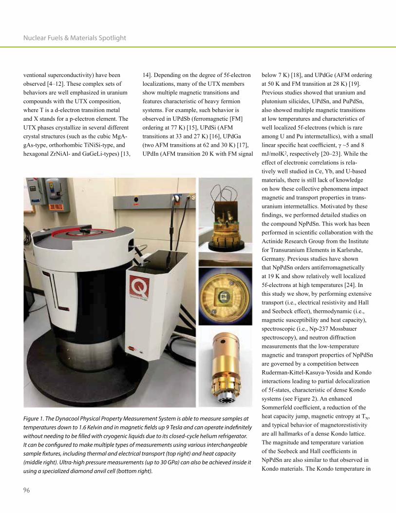
Nuclear Fuels & Materials Spotlight
96
ventional superconductivity) have been observed [4–12]. These complex sets of behaviors are well emphasized in uranium compounds with the UTX composition, where T is a d-electron transition metal and X stands for a p-electron element. The UTX phases crystallize in several different crystal structures (such as the cubic MgA-gAs-type, orthorhombic TiNiSi-type, and hexagonal ZrNiAl- and GaGeLi-types) [13,
14]. Depending on the degree of 5f-electron localizations, many of the UTX members show multiple magnetic transitions and features characteristic of heavy fermion systems. For example, such behavior is observed in UPdSb (ferromagnetic [FM] ordering at 77 K) [15], UPdSi (AFM transitions at 33 and 27 K) [16], UPdGa (two AFM transitions at 62 and 30 K) [17], UPdIn (AFM transition 20 K with FM signal
below 7 K) [18], and UPdGe (AFM ordering at 50 K and FM transition at 28 K) [19]. Previous studies showed that uranium and plutonium silicides, UPdSn, and PuPdSn, also showed multiple magnetic transitions at low temperatures and characteristics of well localized 5f-electrons (which is rare among U and Pu intermetallics), with a small
mJ/molK2, respectively [20–23]. While the effect of electronic correlations is rela-tively well studied in Ce, Yb, and U-based materials, there is still lack of knowledge on how these collective phenomena impact magnetic and transport properties in trans-uranium intermetallics. Motivated by these
the compound NpPdSn. This work has been
Actinide Research Group from the Institute for Transuranium Elements in Karlsruhe, Germany. Previous studies have shown that NpPdSn orders antiferromagnetically at 19 K and show relatively well localized 5f-electrons at high temperatures [24]. In this study we show, by performing extensive transport (i.e., electrical resistivity and Hall and Seebeck effect), thermodynamic (i.e., magnetic susceptibility and heat capacity), spectroscopic (i.e., Np-237 Mossbauer spectroscopy), and neutron diffraction measurements that the low-temperature magnetic and transport properties of NpPdSn are governed by a competition between Ruderman-Kittel-Kasuya-Yosida and Kondo interactions leading to partial delocalization of 5f-states, characteristic of dense Kondo systems (see Figure 2). An enhanced
heat capacity jump, magnetic entropy at TN, and typical behavior of magnetorestistivity are all hallmarks of a dense Kondo lattice. The magnitude and temperature variation
NpPdSn are also similar to that observed in Kondo materials. The Kondo temperature in
Figure 1. The Dynacool Physical Property Measurement System is able to measure samples at temperatures down to 1.6 Kelvin and in magnetic fields up 9 Tesla and can operate indefinitely without needing to be filled with cryogenic liquids due to its closed-cycle helium refrigerator. It can be configured to make multiple types of measurements using various interchangeable sample fixtures, including thermal and electrical transport (top right) and heat capacity (middle right). Ultra-high pressure measurements (up to 30 GPa) can also be achieved inside it using a specialized diamond anvil cell (bottom right).
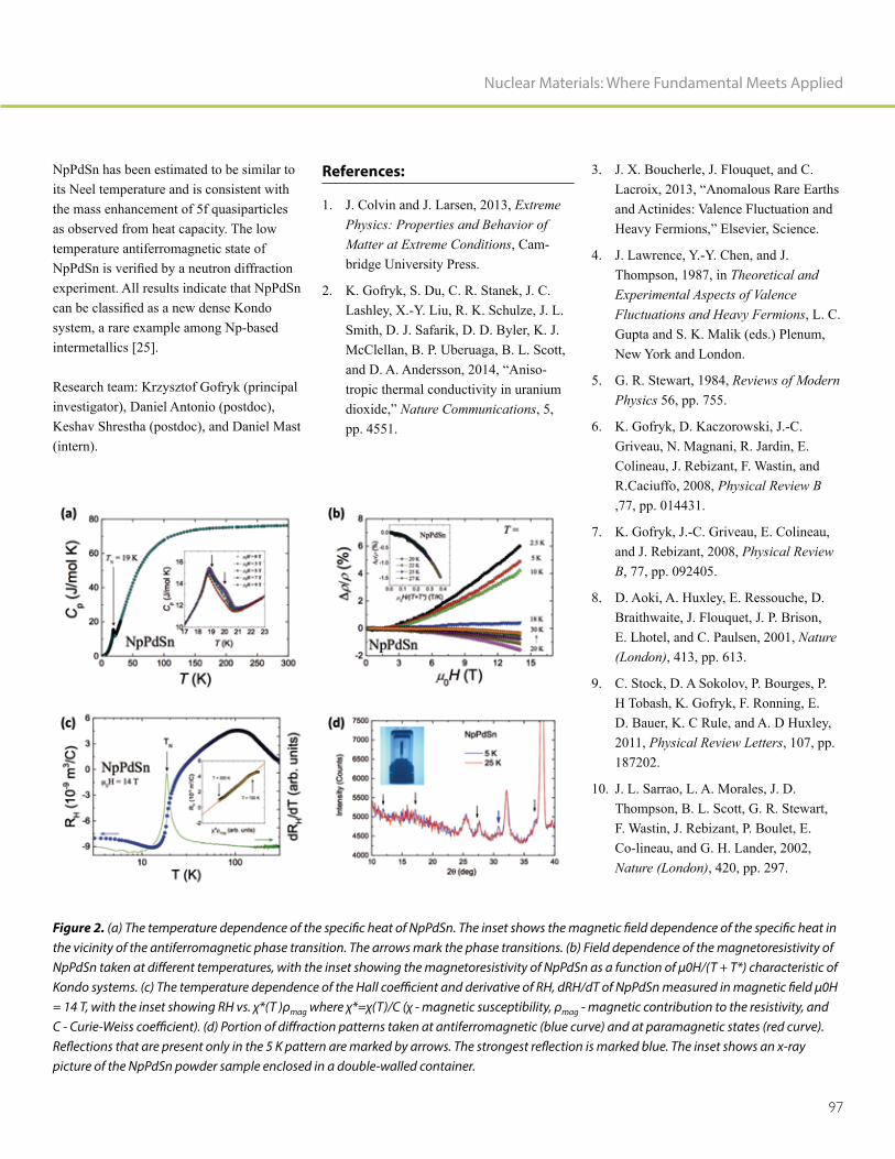
97
Nuclear Materials: Where Fundamental Meets Applied
NpPdSn has been estimated to be similar to its Neel temperature and is consistent with the mass enhancement of 5f quasiparticles as observed from heat capacity. The low temperature antiferromagnetic state of
experiment. All results indicate that NpPdSn
system, a rare example among Np-based intermetallics [25].
Research team: Krzysztof Gofryk (principal investigator), Daniel Antonio (postdoc), Keshav Shrestha (postdoc), and Daniel Mast (intern).
References:
1. J. Colvin and J. Larsen, 2013, Extreme Physics: Properties and Behavior of Matter at Extreme Conditions, Cam-bridge University Press.
2. K. Gofryk, S. Du, C. R. Stanek, J. C. Lashley, X.-Y. Liu, R. K. Schulze, J. L. Smith, D. J. Safarik, D. D. Byler, K. J. McClellan, B. P. Uberuaga, B. L. Scott,
-tropic thermal conductivity in uranium
Nature Communications, 5, pp. 4551.
3. J. X. Boucherle, J. Flouquet, and C.
and Actinides: Valence Fluctuation and
4. J. Lawrence, Y.-Y. Chen, and J. Thompson, 1987, in Theoretical and Experimental Aspects of Valence Fluctuations and Heavy Fermions, L. C. Gupta and S. K. Malik (eds.) Plenum, New York and London.
5. G. R. Stewart, 1984, Reviews of Modern Physics 56, pp. 755.
6. K. Gofryk, D. Kaczorowski, J.-C. Griveau, N. Magnani, R. Jardin, E. Colineau, J. Rebizant, F. Wastin, and R.Caciuffo, 2008, Physical Review B ,77, pp. 014431.
7. K. Gofryk, J.-C. Griveau, E. Colineau, and J. Rebizant, 2008, Physical Review B, 77, pp. 092405.
8. D. Aoki, A. Huxley, E. Ressouche, D. Braithwaite, J. Flouquet, J. P. Brison, E. Lhotel, and C. Paulsen, 2001, Nature (London), 413, pp. 613.
9. C. Stock, D. A Sokolov, P. Bourges, P. H Tobash, K. Gofryk, F. Ronning, E. D. Bauer, K. C Rule, and A. D Huxley, 2011, Physical Review Letters, 107, pp. 187202.
10. J. L. Sarrao, L. A. Morales, J. D. Thompson, B. L. Scott, G. R. Stewart, F. Wastin, J. Rebizant, P. Boulet, E. Co-lineau, and G. H. Lander, 2002, Nature (London), 420, pp. 297.
Figure 2. (a) The temperature dependence of the specific heat of NpPdSn. The inset shows the magnetic field dependence of the specific heat in the vicinity of the antiferromagnetic phase transition. The arrows mark the phase transitions. (b) Field dependence of the magnetoresistivity of NpPdSn taken at different temperatures, with the inset showing the magnetoresistivity of NpPdSn as a function of μ0H/(T + T*) characteristic of Kondo systems. (c) The temperature dependence of the Hall coefficient and derivative of RH, dRH/dT of NpPdSn measured in magnetic field μ0H = 14 T, with the inset showing RH vs. χ*(T )ρmag where χ*=χ(T)/C (χ - magnetic susceptibility, ρmag - magnetic contribution to the resistivity, and C - Curie-Weiss coefficient). (d) Portion of diffraction patterns taken at antiferromagnetic (blue curve) and at paramagnetic states (red curve). Reflections that are present only in the 5 K pattern are marked by arrows. The strongest reflection is marked blue. The inset shows an x-ray picture of the NpPdSn powder sample enclosed in a double-walled container.
Nuclear Fuels & Materials Spotlight
98
11. D. Aoki, Y. Haga, T. D. Matsuda, N. Tateiwa, S. Ikeda, Y. Homma, H. Sakai, Y. Shiokawa, E. Yamamoto, A. Nakamura, R. Settai, and Y. Onuki, 2007, Journal of the Physical Society of Japan, 76, pp. 063701.
12. K. Gofryk, J.-C. Griveau, E. Colineau, J. P. Sanchez, J. Rebizant, and R. Caci-uffo, 2009, Physical Review B, 79, pp. 134525.
13. R. A. Robinson, A. C. Lawson, V. Sechovsky, L. Havela, Y. Kergadallan, H. Nakotte, F. R. de Boer, 1994, Journal of Alloys and Compounds, 213, pp. 528.
14. V. Sechovsky, L. Havela, F. R. de Boer, E. Bruck, 1992, Journal of Alloys and Compounds, 181, pp. 179.
15. K. Gofryk and D. Kaczorowski, 2006, Journal of Physics: Condensed Matter, 18, pp. 3887.
16. K. Prokes, V. Sechovsky, R. A. Rob-inson, R. Sonntag, P. Svoboda, and F. de Boer, 1997, Physica B: Condensed Matter, 241, pp. 687.
17. V. H. Tran and R. Troc, 1991, Journal of the Less Common Metals, 175, pp. 267.
18. V. H. Tran and R. Troc, 1991, Journal of Magnetism and Magnetic. Materials, 88, pp. 287.
19. V. H. Tran, R. Troc, and D. Badurski, 1990, Journal of Magnetism and Magnetic. Materials, 87, pp. 291.
20. F. R. de Boer, E. Bruck, H. Nakotte, A. V. Andreev, V. Sechovsky, L. Havela, P. Nozar, C. J. M. Denissen, K. H. J. Buschow, B. Vaziri, M. Meissner, H. Maletta, and P. Rogl, 1992, Physical Review B, 176, pp. 275.
21. H. Nakotte, R. A. Robinson, A. Pur-wanto, Z. Tun, K. Prokes, E. Bruck, and F. R. de Boer, 1998, Physical Review B, 58, pp. 9269.
22. R. A. Robinson, A. C. Lawson, J. W. Lynn, and K. H. J. Buschow, 1992, Physical Review B, 45, pp. 2939.
23. K. Gofryk, J.-C. Griveau, E. Colineau, R. Jardin, J. Rebizant, F. Wastin, and R. Caciuffo, 2009, Journal of Nuclear Materials, 385, pp. 46.
24. K. Gofryk, J.-C. Griveau, R. Jardin, E. Colineau, J. Rebizant, F. Wastin, and R. Caciuffo, 2009, Acta Physica Polonica A, 115, pp. 80.
25. K. Shrestha, D. Antonio, J-C. Griveau, K. Prokes, E. Colineau, P. Gaczynski, R.
submitted to Physical Review B.

99
Nuclear Materials: Where Fundamental Meets Applied
Krzysztof Gofryk
Krzysztof Gofryk, Ph.D., is a scientist in the Fuel Design and Development department at INL. He has been working on physical, especially thermal and thermodynamic, properties of actinide materials over the last 15 years. Dr. Gofryk received his Ph.D in Physics from the Institute of Low Temperature and Structure Research, Polish Academy of Sciences in 2006. He continued his research at the Institute for Transuranium Elements (Germany) and at Los Alamos and Oak Ridge National Laboratories. His current research is related to thermodynamic and transport properties of nuclear materials, especially under extreme conditions. He has
papers. He is also a recipient of the DOE Early Career Award (2015), INL's Outstand-ing Paper by Early Career Scientist (2015), Los Alamos National Laboratory Postdoc Distinguished Performance Award (2012), and European Commission JRC Best Young Scientist Award (2009).

100
Exploiting Nuclear Power for
In-Pile Measurements
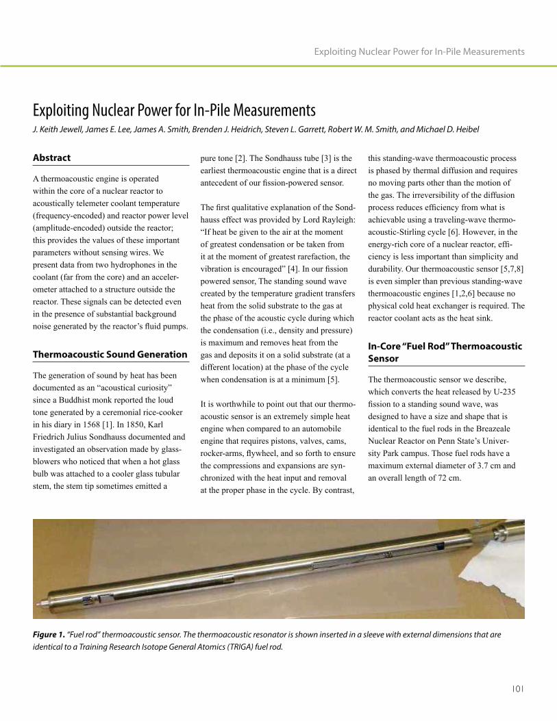
101
Exploiting Nuclear Power for In-Pile Measurements
Exploiting Nuclear Power for In-Pile MeasurementsJ. Keith Jewell, James E. Lee, James A. Smith, Brenden J. Heidrich, Steven L. Garrett, Robert W. M. Smith, and Michael D. Heibel
Abstract
A thermoacoustic engine is operated within the core of a nuclear reactor to acoustically telemeter coolant temperature (frequency-encoded) and reactor power level (amplitude-encoded) outside the reactor; this provides the values of these important parameters without sensing wires. We present data from two hydrophones in the coolant (far from the core) and an acceler-ometer attached to a structure outside the reactor. These signals can be detected even in the presence of substantial background
Thermoacoustic Sound Generation
The generation of sound by heat has been
since a Buddhist monk reported the loud tone generated by a ceremonial rice-cooker in his diary in 1568 [1]. In 1850, Karl Friedrich Julius Sondhauss documented and investigated an observation made by glass-blowers who noticed that when a hot glass bulb was attached to a cooler glass tubular stem, the stem tip sometimes emitted a
pure tone [2]. The Sondhauss tube [3] is the earliest thermoacoustic engine that is a direct
-hauss effect was provided by Lord Rayleigh:
of greatest condensation or be taken from it at the moment of greatest rarefaction, the
powered sensor, The standing sound wave created by the temperature gradient transfers heat from the solid substrate to the gas at the phase of the acoustic cycle during which the condensation (i.e., density and pressure) is maximum and removes heat from the gas and deposits it on a solid substrate (at a different location) at the phase of the cycle when condensation is at a minimum [5].
It is worthwhile to point out that our thermo-acoustic sensor is an extremely simple heat engine when compared to an automobile engine that requires pistons, valves, cams,
the compressions and expansions are syn-chronized with the heat input and removal at the proper phase in the cycle. By contrast,
this standing-wave thermoacoustic process is phased by thermal diffusion and requires no moving parts other than the motion of the gas. The irreversibility of the diffusion
achievable using a traveling-wave thermo-acoustic-Stirling cycle [6]. However, in the
-ciency is less important than simplicity and durability. Our thermoacoustic sensor [5,7,8] is even simpler than previous standing-wave thermoacoustic engines [1,2,6] because no physical cold heat exchanger is required. The reactor coolant acts as the heat sink.
In-Core “Fuel Rod” Thermoacoustic
Sensor
The thermoacoustic sensor we describe, which converts the heat released by U-235
designed to have a size and shape that is identical to the fuel rods in the Breazeale Nuclear Reactor on Penn State’s Univer-sity Park campus. Those fuel rods have a maximum external diameter of 3.7 cm and an overall length of 72 cm.
Figure 1. “Fuel rod” thermoacoustic sensor. The thermoacoustic resonator is shown inserted in a sleeve with external dimensions that are identical to a Training Research Isotope General Atomics (TRIGA) fuel rod.

Nuclear Fuels & Materials Spotlight
102
Reactor Core In Situ Measurements
The thermoacoustic sensor was tested during eight irradiation runs in the Breazeale Nuclear Reactor. Irradiation time was limited by provisions from the reactor’s license that
in an experiment, particularly radioactive iodine isotopes, to less than a total activity of 1.5 Ci. As a consequence, the sensor’s irra-diation time was restricted to 7 MW-minutes of reactor operation. Following each run, the experiment was idled, while the unstable iodine isotopes were allowed to decay.
Figure 2 is a time record made during the
of the thermocouple that was brazed to the hot-end of the thermoacoustic resonator and the output of two hydrophones that were located far from the core in the reactor’s coolant pool. Short time fast (i.e., essen-tially sliding-average) Fourier transforms of 10-second time records were produced every 2 seconds and the frequency of only the largest-amplitude spectral component is plotted in Figure 2 for both hydrophones. The thermoacoustic sensor achieved onset at about t = 810 seconds, which is the time the largest amplitude spectral components for both hydrophones coalesced to the same frequency. It is possible to detect a subtle indication of the onset of thermoacoustic oscillations by noting the slight increase in the slope of the thermocouple’s temperature.
Before onset of thermoacoustic oscillations (t < 810 seconds) and after their cessation (t > 1,100 seconds), the frequencies of the dominant spectral components from both hydrophones’ signals are random. During other irradiations at PSU, the reactor was operated at 700, 800 and 900kW (70-90% power).
Figure 3 shows one of several accelerome-ters that were attached to structures external to the reactor’s coolant pool. The sonogram displays the frequency of the detected vibra-tion as a function of time, with the amplitude of the signal coded as color from blue to yellow. The major frequency recorded from the accelerometer during the thermoacoustic
oscillations matches that recorded by the hydrophones as shown in Figure 2.
We were able to demonstrate that the fre-quency of the thermoacoustically generated sound provides an accurate determination of the reactor’s coolant temperature (Figure 4). The speed of sound in an ideal gas or
Figure 2. Time record of the resonator’s hot-end temperature and the frequency of the largest spectral component received by two hydrophones at different locations. The temperature of a Type-K thermocouple brazed to the hot-end of the thermoacoustic resonator is plotted as the black diamonds. The purple “x” and red “*” symbols are the frequencies of the largest spectral component within the frequency range between 1,320 Hz ≤ f ≤ 1,400 Hz. The reactor reached full power (i.e., 1.0 MW) at t = 800 seconds. The reactor power was reduced to 800 kW at t = 1,060 seconds, then the reactor was shut down at t = 1,100 seconds.
Figure 3. Time record spectrogram (right) of the vibration signal received by an out-of-water accelerometer mounted on a structure (left) that extends into the reactor pool.

103
Exploiting Nuclear Power for In-Pile Measurements
gas mixture, c, is related to the acoustically averaged absolute (Kelvin) temperature, T; the mean molecular mass of the gas mixture,
5/3; and the Universal Gas Constant, = (8.314472 ± 0.000015) J·mol-1·K-1
T / M)1/2. The fundamental resonance fre-quency of the thermoacoustic sensor occurs when the wavelength of the sound in the
length, L 2 = (c2/4L2 T / 4 M L2) T.
The performance of a thermoacoustic engine as a sensor can be analyzed by plotting the ratio of the square of the measured reso-nance frequency, f2, to the absolute (Kelvin) temperature, T, of the reactor’s coolant. This ratio should remain invariant over the range of temperatures used in the measurements. Figure 4 shows that the sensor output produced values of the f2/T invariant that
vary by only ±0.12%, while the temperature changes by 3.4%.
Conclusions
We have demonstrated the ability to acous-tically telemeter temperature and power information beyond the core of a nuclear reactor without requiring external electrical power or wiring. This type of sensor might have been useful in a reactor accident like that which destroyed the Fukushima com-plex in March 2011. In a commercial reactor,
steel could be used instead of nuclear fuel.
Figure 4. Resonance frequency of the thermoacoustic sensor’s standing-wave for different coolant temperatures. The resonance frequencies corresponding to various temperatures as the pool warmed up are plotted as black squares and their values are given by the left-hand (black) axis that spans ±1.7%. The right-hand (red) axis has the same relative span, but the value of the f2/T invariant, plotted as red diamonds, has a standard deviation of only ±0.12%.
Acknowledgements
The authors are grateful for the support of IST Mirion for fabrication of the resonator and for its fueling. We are also appreciative of the support provided by Penn State’s Radiation Science and Engineering Center. J. A. S. thanks Vivek Agarwal for assistance with the data analysis. The participation of Randall Ali, Joshua Hrisko, and Andrew Bas-com, three of S. L. G.’s graduate students, contributed to the success of these experi-ments. This research was supported by the U.S. Department of Energy’s Idaho National Laboratory and by the Westinghouse Global Technology Development Department of the Westinghouse Electric Company.
References
-acoustic oscillator powered by vaporized
American Journal of Physics, 81(2):pp. 124-126.
Journal of the Acoustical Soci-ety of America, 84(4): pp. 1145-1180.
die Schallschwingungen der Luft in erhitzten Glasröhren und in geteckten
Annals of Physics (Leipzig), 79; pp. 1.
4. J. W. Strutt (Lord Rayleigh), 1878,
Nature, 18; pp. 319-321.
5. R. A. Ali, S. L. Garrett, J. A. Smith, and
thermometry for nuclear reactor IEEE Journal of Instru-
mentation and Measurement, 16(3); pp. 18-25.
Nature, 399; pp. 335-338.

Nuclear Fuels & Materials Spotlight
104
Keith Jewell
Dr. J. Keith Jewell (B.S., Physics, 1992, Kent State University; Ph.D., Nuclear Phys-ics, 1997, Florida State University) has been a research staff member at INL since 1997 and has a wide range of experience in appli-cation of experimental nuclear methods to a diverse collection of programmatic needs.
of Nuclear Energy, National and Homeland
Management, with a broad range of nuclear detection and characterization methods. Dr. Jewell has worked at the National Superconducting Cyclotron Lab at Michigan State University, the Intense Pulsed Neutron at Argonne National Laboratory, and the ORELA facility at Oak Ridge National Laboratory. His current research interests are focused on separate effects testing, com-plex measurement systems, and detection development. He is a collaborator on the NIFFTE TPC Project for making highly
-ments, and leads the INL effort for advanced instrumentation of the TREAT reactor restart effort. His experience ranges from advanced materials and nano-material applications for detectors and instrumentation, nuclear fuels development and fabrication, and spent nuclear fuel assay and waste characteriza-tion, including in pool, ultrasonic inspection of used fuel elements.
7. S. L. Garrett, J. A. Smith, R. W. Smith, W. Robert, B. J. Heidrich and M. D.
Applied Physics Letters, 108(14); pp. 144102, doi; 10.1063/1.4944697.
8. S. L. Garrett, J. A. Smith, R. W. Smith, B. J. Heidrich, and M. D. Heibel, 2016,
to be published in American Nuclear Society’s Nuclear Technology, 195(3)
Dr. Jewell is currently working as the Technical Lead for the Nuclear Science User Facilities program in coordinating irradiation experiments for nuclear fuel and materials research and development.

105
Exploiting Nuclear Power for In-Pile Measurements
James Lee
James E. Lee (B.S., Computer and Industrial Electronics Technology, University of Idaho, and A.T.,Electronics, Idaho State University)
of electronics and electrical engineering. His skills include analog and digital design, instrumentation and control, packaging, electronic fabrication, system prototyping,
Currently he oversees the electronics development lab at the INL Research Center, a position that includes maintenance of the parts inventory that supports INL Research Center (IRC) projects, and development of a rapid prototype system that is easily
fast-pace requirements at the IRC. He holds a B.S. degree in computer and industrial electronics technology from the University of Idaho.
James A. Smith
James A. Smith, Ph.D., is a Materials Char-acterization and Processes Systems Engineer at INL. He attended Iowa State University for his B.S. in Engineering Science and Mechanics and Texas A&M for his M.S. and Ph.D. graduate degrees in Engineering. He has worked at AT&T Bell Laboratories, Corning Incorporated, and the Mayo Clinic prior to joining INL. Jim is an innovative and goal-oriented systems engineer/project manager with over 20 years of diverse expe-rience who solves complex and ambiguous
diligent in envisioning new possibilities and developing visionary strategies that progress toward a shared vision. He is known for quickly turning system concepts into plant prototypes by developing close collabora-tions and understanding customer needs. Jim specializes in developing products and processes through pioneering measurements and data analysis techniques.
Brenden J. Heidrich
Brenden J. Heidrich, Ph.D., is the Nuclear Energy Research and Development Capabil-ity Scientist (Senior Staff Engineer) at INL. He has B.S., M.S. and Ph.D. degrees from Pennsylvania State University (1999, 2003, and 2012) and is a licensed professional nuclear engineer (PA). Dr. Heidrich’s current position involves researching and assessing infrastructure and capabilities to support nuclear energy research and development
of Nuclear Energy. Previous positions include Assistant Director for Irradiation Services and Operations, Radiation Science and Engineering Center, Pennsylvania State University (2000-2014). Responsibilities at Pennsylvania State University involved irradiation engineering and experimental design and modeling and simulation of the research reactor in support of a wide variety of research and commercial work and teaching reactor physics and nuclear security courses. Dr. Heidrich was also a Navy Reactor Operator on the USS Enterprise (1990-1994).
Nuclear Fuels & Materials Spotlight
106
Michael Heibel
Michael Heibel has over 36 years of experi-ence working in Westinghouse pressurized water reactor nuclear engineering, nuclear plant startup, and nuclear plant operations. He supervised or performed initial startup construction and testing at 22 Westinghouse pressurized water reactors. Performed reactor physics testing at various Westing-house, combustion engineering, and Russian designed VVER reactor sites and over 60 reload startup test evolutions. Recognized as a nuclear industry leader in core power distribution measurement systems and techniques, core monitoring systems, reactor startup testing techniques, and new reactor nuclear sensor technology development.Currently, working as a technical program manager for the development and com-mercial implementation of radiation and temperature sensor systems for use in the harsh environments present in nuclear power facilities.
Robert Smith
Robert Smith received his Ph.D. in Acous-tics, M.S. in Engineering Mechanics, and B.S. in Physics, all from Penn State, where he has also been employed for the past 27 years, working on diverse research projects.
worked in the Department of Astronomy on telescope mirrors as part of the development effort for the Hobby-Eberly telescope, which is currently the largest in the continental United States. For this effort, he worked on 1-meter diameter telescope mirrors, perform-
and optical testing, much of the latter carried out in an abandoned 85-ft. elevator shaft in the Penn State University's Beaver Stadium. Subsequently, he worked in the Department of Electrical Engineering, where he provided opto-mechanical engineering expertise for LIDAR instruments used to characterize the earth's atmosphere and remotely sense atmospheric temperature, pressure, rela-tive humidity, and ozone concentration. During the past 15 years, Smith has worked primarily on thermoacoustic cooling devices focusing mostly on implementation of trans-ducers, but with forays into photoacoustics, acoustic metamaterials, acoustic cavitation, acoustic scattering from bubble clouds and other areas. Smith is co-inventor on six issued U.S. patents.
Steven Garrett
Steven Garrett received his Ph.D. in Physics from UCLA in 1977. He continued research
Sussex in England, followed by 2 years in the Physics Department at the University of California at Berkeley as a Fellow of the Miller Institute for Basic Research in Science. Dr. Garrett joined the faculty of the Naval Postgraduate School in 1982, where his research efforts were concentrated
thermoacoustic refrigerators. He left NPS in 1995 to assume his current position as a Professor of Acoustics in the Graduate Program in Acoustics at Penn State, where he is continuing his research in thermoacous-tic engines and refrigerators. In 2001, he was a Fulbright Fellow at the Danish Technical University and in 2008 a Jefferson Fellow in the U.S. State Department, where he served as a Senior Science Advisor for East Asia
of the Acoustical Society of America and recipient of the Popular Science Magazine Award for Environmental Technology, the Helen Caldecott Award for Environmental Technology, the Rolex Award for Enterprise (environment category), and has been issued over two dozen patents.

107
Exploiting Nuclear Power for In-Pile Measurements

108
TPE Upgrade for
Enhancing Safety and Material
Development in
Fusion Nuclear Environment

109
TPE Upgrade for Enhancing Safety and Material Development in Fusion Nuclear Environment
TPE Upgrade for Enhancing Safety and Material Development
in Fusion Nuclear EnvironmentM. Shimada, C. N. Taylor, and B. J. Merrill (Fusion Safety Program, Idaho National Laboratory)
Recently, the Tritium Plasma Experiment (TPE) has undergone major upgrades in its electrical and control systems. New direct current power supplies and a new control center enable remote plasma operations from outside the tritium contamination area, minimizing the possible exposure risk with tritium and beryllium. This upgrade not only improves worker occupational safety, but also enhances TPE plasma performance to better simulate extreme plasma-material conditions expected in a fusion nuclear envi-ronment. Various international collaborations (e.g., United States-Japan, United States-Ko-rea, International Atomic Energy Agency, and International Energy Agency) continue to help enhance world recognition of TPE as the only existing linear plasma device that can advance tritium, nuclear fusion fuel, interaction with fusion materials in a fusion nuclear environment, and provide a one-of-a-kind experimental tritium behavior database in material development.
Introduction
Fusion power promises to provide electricity generation with outstanding safety and environmental performance. Safety plays a crucial role in fusion material selection because tritium behavior in materials determines two key safety evaluation source terms: (1) in-vessel inventory source term and (2) ex-vessel release term for licensing fusion facilities. For example, the decision by the International Tokamak Experimental Reactor (ITER) organization to exclude carbon is based on predictions of unacceptable levels of tritium retained in co-deposited carbon layers. Safe operation
of ITER dictates that in-vessel tritium concentrations retained within plasma-fac-ing components (PFCs) must remain at acceptable levels. Regulatory limits are set to 1,000 g-T in vessel and 0.0001 g T/m3 in the reactor cooling water in ITER [1]. A critical challenge for long-term operation of ITER and future fusion reactor will be development of plasma-facing materials that demonstrate erosion resistance to intense
under the extreme fusion nuclear environ-ment, while minimizing in-vessel inventories and ex-vessel permeation of tritium (fuel for
Tungsten, a primary candidate material for the future reactor’s divertor, is expected to receive a neutron dose of tens of dis-placements per atom of radiation damage in a fusion demonstration reactor and future fusion power reactors. Under a
tritium is migrated in bulk and trapped in a radiation-induced trap site (up to 1 at. % T/W) in neutron-irradiated tungsten [2,3]. The microstructural evolution from intense
and irradiation effects (e.g., displacement damage, transmutation, and gamma radi-ation) can also alter near surface material evolution, erosion, dust production, and tri-tium behavior in burning plasma operation. Plasma material interaction (PMI) deter-mines a boundary condition for diffusing tritium into bulk PFCs. Fully addressing the challenges described above will undoubtedly require a range of modeling and experi-ments executed at many non-nuclear and nuclear facilities. Direct work with tritium,
neutron-irradiated materials, and a gamma radiation environment is indispensable for material development in a fusion nuclear environment. The advancement of tritium and nuclear PMI sciences is crucial for successful development of reliable PFCs and a tritium fuel cycle in burning plasma long pulse operation.
Tritium Plasma Experiment
Upgrade
Idaho National Laboratory (INL) operates a linear plasma device, known as TPE. TPE is unique in that it combines four special-ized elements: (a) the use of tritium, (b) a
ability to handle radioactive materials, and (d) beryllium [4,5]. TPE is located within the Safety and Tritium Applied Research (STAR) facility, which is a U.S. Department of Energy (DOE) Less than Hazard Category 3 nuclear facility [6] and is licensed to handle tritium inventory up to 16,000 Ci (5.9x10¹⁴ Bq) and moderately activated/neutron-irradiated materials. Despite its age, TPE still stands as the only existing
handle both tritium and neutron-irradiated material to study tritium and nuclear PMI in a fusion nuclear environment [4,5]. Recently, TPE has undergone major upgrades in its electrical and control systems and, in November 2015, TPE successfully achieved
from outside the contamination area after a
a photo of the new TPE power supplies and control center outside the contamination area after the 3-year upgrade. Details about

Nuclear Fuels & Materials Spotlight
110
the electrical upgrade, enhanced operational safety, and improved plasma performance were summarized in a previous publication [5]. Figure 2(a) shows the discharge cur-
sources. The PISCES-A device operates
23m-2s-1) with high discharge current: Idis [8]. With the new power supply’s maximum current: (IPS
max)new of 750 A, we plan to increase Idis > 200 A, which is similar to PISCES-A near the future. TPE can achieve a discharge power up to Pdis
max> 20 kW (Figure 2(a)). The simple linear scaling estimates show that
i max of >1.0x10²³ m-2s-1 with new power supplies (Figure 2(b)). Heat
voltage can be simply expressed as qheat
heat with a new
i max of >1.0x10²³ m-2s-1 in Figure 2(c). This simple estimate also shows that TPE will be capable
of reaching qheat of >1 MWm-2 with new power supplies.
Improvements in Diagnostic
Capabilities for Tritium-Exposed
and Radioactive Samples
Efforts to improve surface diagnostics capabilities for tritium-exposed and radio-active samples are being carried out at the STAR facility as summarized in Table 1. The thermal desorption spectroscopy system can distinguish small mass difference between helium (4.0026 amu) and D2 (4.0282 amu) and measure total retention in deuterium and tritium retention in neutron-irradiated materials. A Doppler broadening positron annihilation spectroscopy system is recently developed with a single high-purity ger-manium detector (Ortec, GMX series) to investigate characterizations of radiation defects (e.g., vacancy, vacancy-cluster, and voids) and occupancy of hydrogen
isotopes and helium in neutron-irradiated material. An optical microscope (i.e., Nikon Optiphot-100) with a two-dimensional charge-coupled device (CCD) camera (i.e., PAXcam) provides a two-dimensional optical microscope image of the surface mor-phologies (e.g., blister formation, cracks, and melting) in neutron-irradiated materials. A refurbished liquid scintillation counter (i.e., Beckman LS6500) was recently installed in the STAR facility to measure the tritium concentration in the tritiated liquid with a superb detection sensitivity of one parts per quadrillion of tritiated water. An imaging
enables us to measure a two-dimensional image of a relative tritium concentration on the surface by a tritium imaging plate
Figure 1. Photo of new TPE power supplies and control center outside the contamination area after the 3-year upgrade.
Figure 2. (a) Discharge current-voltage characteristic curve of TPE’s old power supply and PISCES-A [7], (b) discharge power dependence on ion flux density, and (c) ion flux density dependence on heat flux density.

111
TPE Upgrade for Enhancing Safety and Material Development in Fusion Nuclear Environment
of tritium by cutting a tritium-implanted sample with a diamond wire saw. A scanning Auger microscope (i.e., Perkin Elmer PHI 660) and x-ray photoelectron spectroscopy (i.e., Perkin Elmer PHI 5400) are being transferred from another INL facility and being reassembled at the STAR facility to add critical surface diagnostic capabilities for tritium-exposed and radioactive mate-rials. The scanning Auger microscope will provide high-resolution, spatially resolved chemical images of elemental composition on the surface. The x-ray photoelectron spec-troscopy will provide elemental composition and the chemical and electronic state of each element on the surface and also measure the
tritium-exposed and radioactive materials.
International Collaborations
The unique capability of TPE and INL’s technical leadership are recognized on a number of international collaborative tasks for the International Atomic Energy Agency, the International Energy Agency, and the United States-Japan collaboration. In the International Atomic Energy Agency’s
on Plasma-Wall Interaction with Irradiated Tungsten and Tungsten Alloys in Fusion
apparatus to provide a valuable database on the effects of neutron irradiation in microstructure and transport of tritium in tungsten-based plasma-facing materials among a total of 19 leading experts from China, Korea, India, Japan, the European Union, and the United States. TPE’s tritium retention databases were utilized in the
safety assessment from Task 1 (In-Vessel Tritium Source Term) of the International Energy Agency’s Implementing Agreement on the Environmental, Safety, and Economic Aspects of Fusion Power. In addition, the United States-Japan PHENIX project helps enhance world recognition of TPE as an only existing linear plasma device that can advance tritium, nuclear fusion fuel, interac-tion with fusion materials in a fusion nuclear environment, and provide a one-of-a-kind experimental tritium behavior database in material development.
Conclusions
Enhanced plasma performance in TPE and improved surface diagnostics capabilities for tritium-exposed and radioactive samples at the STAR facility will help provide a one-of-a-kind experimental tritium behavior database for material development in a fusion nuclear environment. International collaborations (e.g., United States-Japan, United States-Korea, International Atomic Energy Agency, and International Energy Agency) continue to help enhance world recognition of the unique capabilty of TPE and INL’s technical leadership in plasma material interaction and material develop-ment in fusion.
Acknowledgements
This work was prepared for the U.S. DOE
DE-AC07-05ID14517.
Table 1. Surface diagnostic capabilities for tritium exposed and radioactive samples at STAR.
Diagnostic at the STAR FacilityHandling Tritium Exposed Sample
Handling Radioactive Sample
Thermal desorption spectroscopy with 1 to 100 amu and 1 to 6 amu quadrupole mass spectrometers (MKS eVision+ and IP Microvision)
Yes Yes
Positron annihilation spectroscopy with a single high-purity germanium detector (Ortec GMX series)
Yes Yes
Optical microscope (Nikon Optiphot-100) with two dimensional CCD camera (PAXcam) Yes Yes
Liquid scintillation counter (Beckman LS6500) Yes No
Imaging plate reader (Fujifilm FLA-7000) Yes Yes
Scanning Auger microscope (Perkin Elmer PHI 660) Yes Yes
X-ray photoelectron spectroscopy (Perkin Elmer PHI 5400) Yes Yes
Glow discharge optical emission spectroscopy (Horiba GO-PROFILER 2) Yes Yes

Nuclear Fuels & Materials Spotlight
112
References
1. ITER Preliminary Safety Report (RPrS), 2011, 3ZR2NC.
2. Y. Hatano1, M. Shimada, T. Otsuka, Y. Oya, V. K. Alimov, M. Hara, J. Shi, M. Kobayashi, T. Oda, G. Cao, K. Okuno, T. Tanaka, K. Sugiyama, J. Roth, B. Tyburska-Puschel, J. Dorner, N. Yoshida, N. Futagami, H. Watanabe, M. Hatakeyama, H. Kurishita, M. Sokolov, and Y. Katoh, 2013, Nuclear Fusion, 53, 073006.
3. M. Shimada, G. Cao, T. Otsuka, M. Hara, M. Kobayashi, Y. Oya, and Y. Hatano, 2015, Nuclear Fusion, 55, 013008.
4. M. Shimada, R. D. Kolasinski, J. P. Sharpe, and R. A. Causey, 2011, Review
, 82, 083503.
5. M. Shimada, C. N. Taylor, R. J. Pawelko, R. D. Kolasinski, D. A. Buchenauer, L. C. Cadwalladar, and B. J. Merrill, Fusion Engineering and Design, accepted for publication.
and Accident Analysis Techniques for Compliance with DOE Order 5480.23, Nuclear Safety Analysis ReportStandard DOE-STD-1027-92.
7. D. M. Goebel, Y. Hirooka, and T. A. Sketchy, 1985, Instruments, 56, 091717.

113
TPE Upgrade for Enhancing Safety and Material Development in Fusion Nuclear Environment
Brad Merrill
Brad Merrill is a Directorate Fellow for the Nuclear Science and Technology directorate, and the Group Leader of the Fusion Safety Program in the Fusion Hydrogen & Measure Science department at INL. In this capacity, he is the lead for computer code develop-ment for fusion safety. He also works on licensing, fusion safety code development,
International Thermalnuclear Experimental Reactor (ITER). Merrill has more than 43 years of experience at INL in thermal sci-ence safety analysis and safety development. He also has experience in thermal hydrau-lics, electromagnetics, computer codes for
tridium transport and diffusion in materials. He holds a B.S. in nuclear engineering from Oregon State University.
Masashi Shimada
Masashi Shimada, Ph.D., is a Plasma Material Scientist in Fusion Safety Program at INL. He attended University of California – San Diego for his Ph.D. in Engineering Physics. He is the experimental leader of the Safety and Tritium Applied Research (STAR) facility at INL to support the DOE
Energy Science (FES) tritium and safety research, and conducts experiments and numerical modeling of hydrogen isotopes, especially tritium, and transport in materials for DOE-SC fusion applications and for
awarded the Miya-Abdou Fusion Nuclear Technology Award, which recognizes signif-icant contributions in development of fusion nuclear technologies, at the International Symposium on Fusion Nuclear Technology
this award in 13 years.
Chase Taylor
Chase N. Taylor, Ph.D., is a research scientist for the Fusion, Hydrogen, and Measurement Sciences department at INL. He obtained his M.S. and Ph.D. degrees from Purdue University in nuclear engi-neering (2011 and 2012), and his BS in mechanical engineering from Idaho State University (2008). Dr. Taylor’s expertise is in radiation interaction with materials, hydrogen isotopes, and numerous materials characterization and spectroscopic tech-niques. Current research investigates tritium retention in neutron-activated, plasma-facing components for magnetic fusion energy. Dr. Taylor joined the Fusion Safety Program at INL in 2012.

16-50318 • INL/EXT-16-40163