november 22, 2011 10 cfr 50.90 subject: duke energy ... · and preferential weld attack. the change...
TRANSCRIPT

Duke JAMES R. MORRIS
DrEnergy® Vice President
Duke EnergyCatawba Nuclear Station4800 Concord RoadYork, SC 29745
803-701-4251803-701-3221 fax
November 22, 2011 10 CFR 50.90
U.S. Nuclear Regulatory CommissionAttention: Document Control DeskWashington, D.C. 20555
Subject: Duke Energy Carolinas, LLC (Duke Energy)Catawba Nuclear Station, Units 1 and 2Docket Numbers 50-413 and 50-414Proposed Technical Specifications (TS) and Bases AmendmentTS and Bases 3.7.8, Nuclear Service Water System (NSWS)
Pursuant to 10 CFR 50.90, Duke Energy is requesting amendments to the CatawbaFacility Operating Licenses and TS. This request is to modify the subject TS and Basesto allow single discharge header operation of the NSWS (Duke Energy designation"RN") for a time period of 14 days. The change, which is being requested on apermanent basis, will facilitate future maintenance of the Unit 2 NSWS dischargeheaders in the Auxiliary Building. Specifically, the change will allow each of thedischarge headers to be removed from service for refurbishment (i.e., cleaning andcoating) due to piping degradation from various corrosion mechanisms, includingMicrobiological Induced Corrosion (MIC), general corrosion, under deposit corrosion,and preferential weld attack. The change will also facilitate future inspections of therefurbished 42-inch NSWS discharge piping on a periodic basis, in conformance withregulatory requirements. These activities will ensure the long-term reliability of theNSWS.
The contents of this amendment request package are as follows:
Attachment 1 provides the technical and regulatory evaluations associated with theproposed changes. Attachment 2 provides the marked up TS pages showing theproposed changes. Retyped (clean) TS pages will be provided to the NRC immediatelyprior to issuance of the approved amendments. Attachment 3 provides the marked upTS Bases pages reflecting the proposed changes to the TS. The marked up TS Basespages are being provided to the NRC for information only. Attachment 4 is a list of NRCcommitments being made in this submittal.
Duke Energy is requesting NRC review and approval of this amendment requestsubmittal within one year from the date of submittal in order to support planned activitieson the Unit 2 NSWS discharge headers in the Auxiliary Building. The initial activitiesinclude cleaning and coating of the affected piping. Future activities will include periodicinspections of the refurbished piping to ensure that it is performing satisfactorily.
www, duke-energy. com

U.S. Nuclear Regulatory CommissionPage 2November 22, 2011
Duke Energy is requesting a 60-day implementation period in conjunction with theseamendments. Implementation of these amendments will require changes to theUpdated Final Safety Analysis Report (UFSAR). The following UFSAR sections maypotentially be impacted: 3.1, "Conformance with General Design Criteria"; 6.6,"Inservice Inspection of Class 2 and 3 Components"; 7.4.2, "Nuclear Service WaterSystem Instrumentation and Control"; 9.2.1, "Nuclear Service Water"; 9.2.5, "UltimateHeat Sink"; and Table 9.4, "Nuclear Service Water System Failure Analysis". NecessaryUFSAR changes will be submitted to the NRC in accordance with 10 CFR 50.71(e).
This amendment request submittal is considered to be a risk-based submittal inaccordance with the guidance provided in NRC Regulatory Guide 1.200, "An Approachfor Determining the Technical Adequacy of Probabilistic Risk Assessment Results forRisk-Informed Activities".
In accordance with Duke Energy administrative procedures and the Quality AssuranceProgram Topical Report, this amendment request submittal has been previouslyreviewed and approved by the Catawba Plant Operations Review Committee.
Pursuant to 10 CFR 50.91, a copy of this amendment request submittal is being sent to
the appropriate State of South Carolina official.
Inquiries on this matter should be directed to L.J. Rudy at (803) 701-3084.
Very truly yours,
James R. Morris
LJR/s
Attachments

U.S. Nuclear Regulatory CommissionPage 3November 22, 2011
James R. Morris affirms that he is the person who subscribed his name to the foregoingstatement, and that all the matters and facts set forth herein are true and correct to thebest of his knowledge.
JamV R. Morris, Vice President
Subscribed and sworn to me: 1/- D -//Date
Notary Public
My commission expires: R-- j:7' - dý0•,Date
SEAL
*, 0 I,
.'.Vf-\
U.S. Nuclear Regulatory CommissionPage 4November 22, 2011
xc (with attachments):
V.M. McCreeRegional AdministratorU.S. Nuclear Regulatory Commission - Region IIMarquis One Tower245 Peachtree Center Ave., NE Suite 1200Atlanta, GA 30303-1257
G.A. Hutto, IIISenior Resident Inspector (Catawba)U.S. Nuclear Regulatory CommissionCatawba Nuclear Station
J.H. Thompson (addressee only)NRC Project Manager (Catawba)U.S. Nuclear Regulatory CommissionOne White Flint North, Mail Stop 8-G9A11555 Rockville PikeRockville, MD 20852-2738
S.E. JenkinsManagerRadioactive & Infectious Waste ManagementDivision of Waste ManagementSouth Carolina Department of Health and Environmental Control2600 Bull St.Columbia, SC 29201

ATTACHMENT 1
TECHNICAL AND REGULATORY EVALUATIONS

Subject: License Amendment Request to Allow Nuclear Service Water SystemSingle Auxiliary Building Discharge Header Operation for a Time Periodof 14 Days
1. DESCRIPTION
2. PROPOSED CHANGE
3. BACKGROUND
4. TECHNICAL EVALUATION
5. REGULATORY EVALUATION
5.1 Applicable Regulatory Requirements/Criteria
5.2 Precedent
5.3 No Significant Hazards Consideration
5.4 Conclusions
6. ENVIRONMENTAL CONSIDERATION
7. REFERENCES
Attachment 1 Page 1

1. DESCRIPTION
Pursuant to 10 CFR 50.90, Duke Energy is requesting amendments to the CatawbaFacility Operating Licenses and TS. This request is to modify the subject TS and Basesto allow single discharge header operation of the NSWS (Duke Energy designation"RN") for a time period of 14 days. The change, which is being requested on apermanent basis, will facilitate future maintenance of the Unit 2 NSWS dischargeheaders in the Auxiliary Building. Specifically, the change will allow each of thedischarge headers to be removed from service for refurbishment (i.e., cleaning andcoating) due to piping degradation from various corrosion mechanisms, includingMicrobiological Induced Corrosion (MIC), general corrosion, under deposit corrosion,and preferential weld attack. The change will also facilitate future inspections of therefurbished 42-inch NSWS discharge piping on a periodic basis, in conformance withregulatory requirements. These activities will ensure the long-term reliability of theNSWS.
Attachment 1 Page 2
2. PROPOSED CHANGE
The NSWS single discharge header alignment is being proposed to allow therefurbishment of a portion of the large diameter (42-inch) Unit 2 NSWS discharge pipingin the Auxiliary Building (up to the wall at column line "QQ"). This alignment will notaffect the NSWS return header piping to the Standby Nuclear Service Water Pond(SNSWP) that is buried (downstream of NSWS isolation valves 1 RN58B and 1 RN63A).Therefore, the discharge flow paths of the Unit 1 and Unit 2 diesel generators areunaffected. The piping addressed by the single discharge header alignment is withinthe Auxiliary Building. The single discharge header alignment of the NSWS is beingproposed to allow a portion of each of the NSWS return headers in the Auxiliary Buildingto the SNSWP to be removed from service for cleaning, repairs, and coating, and forperiodic follow-up inspections. The proposed TS changes will allow for a CompletionTime of 14 days while in the single discharge header alignment.
The NSWS Single Discharge Header Alignment
The NSWS single discharge header alignment can be described as follows:
1. Unit 2 must be in Mode 5, 6, or No Mode.2. Unit 1 is in Mode 1, 2, 3, or 4.3. A portion (Unit 2 side) of the shared NSWS train discharge piping to the SNSWP is
isolated, resulting in a TS Condition entry for Unit 1.4. NSWS return header crossover valves 1 RN53B and 1 RN54A are open with power
removed and therefore will not automatically close (automatic closure is required ona low-low NSWS suction pit level signal or on a transfer to Auxiliary Shutdown Paneloperation). This allows the Unit 1 NSWS components on the affected train todischarge through the opposite train's discharge header, which is aligned to theSNSWP.
5. Both NSWS trains on Unit 1, and the in-service NSWS train on Unit 2, are aligned todischarge to the SNSWP. The normal non-safety related Lake Wylie discharge flowpath is isolated since NSWS is aligned (both suction and discharge) to the SNSWP.
6. The Unit 2 NSWS non-essential header is isolated.
Notes:
1. The NSWS cannot be aligned in the single discharge header alignment if the systemis already in the single supply header alignment, which is described in TS 3.7.8 andits associated Bases. The combination of these two alignments has not beenanalyzed.
2. Unit 2 must be in Mode 5, 6, or No Mode, which are "not applicable" modes for theComponent Cooling Water (CCW) System (Duke Energy designation "KC") and theContainment Spray System (CSS) (Duke Energy designation "NS"). The NSWSdischarge cooling water flow paths for the Unit 2 CCW System and the CSS heatexchangers on the affected train are isolated during NSWS single discharge headeralignment.
Attachment 1 Page 3
3. While the NSWS is aligned in the single discharge header alignment, Unit 1 is in aTS Condition for the affected NSWS train (i.e., the train that has its normal safetyrelated flow path to the SNSWP isolated).
4. With the NSWS aligned to the SNSWP, a low-low NSWS suction pit level signalshould not occur; however, NSWS discharge header crossover valves 1 RN53B and1 RN54A must remain open while in the single discharge header alignment. With thecrossover valves open, the components on the affected Unit 1 NSWS train candischarge through the operable NSWS train's discharge header, which is aligned tothe SNSWP.
5. No failures (including pipe ruptures) are required to be postulated on the operableUnit 1 NSWS train's equipment or on the shared equipment on the operable NSWStrain, since Unit 1 will be in a TS Condition as a result of the inoperable NSWS train.The proposed Completion Time for the NSWS in this alignment is 14 days. While inthis alignment, the NSWS is not required to withstand another single failure or piperupture on the in-service train, as described in Section 3.6.2.1.2 of the CatawbaUFSAR. A Probabilistic Risk Assessment (PRA) calculation has been performedand has verified that the Completion Time of 14 days is acceptable.
The diagrams that follow show the NSWS single discharge header alignments for NSWSTrains A and B.
Attachment 1 Page 4
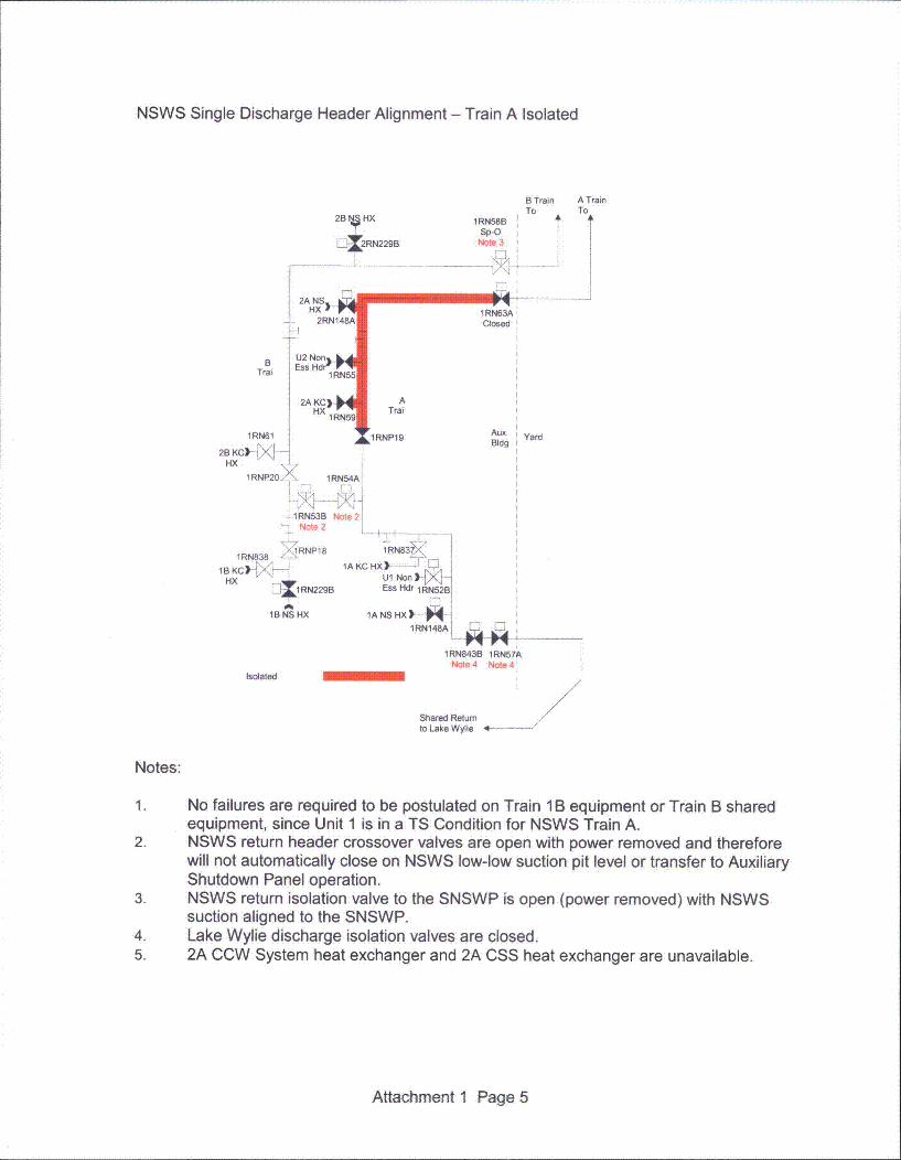
NSWS Single Discharge Header Alignment - Train A Isolated
2B6t HX
E12RN229B
B Train A TrainTo To
IRN58BSp-O
Note 3
2A NSHX
.. 2RN148A
148
Trai 1 RN55
HX1RN5 9
RN61
1 RN63ADlosed
ATrai
1i 1RNP19 Aux YardBldg
2B KC)->KHX
1 R NP20 l 1 RN54A
-1RN53B Note 2Note 2
I8 lRNP181RN838 ...
1BKC) `IAK
HX }11RN229B
1B NS HX
Isolated
1RN83
CHX)----UL Non IN,Ess Hdr 1RN52B
1A NS HX) .-.--1RN148A •
1RN843B 1RN57ANote4 Note 4
Shared Returnto Lake Wylie 4- -..
Notes:
1. No failures are required to be postulated on Train 1 B equipment or Train B sharedequipment, since Unit 1 is in a TS Condition for NSWS Train A.
2. NSWS return header crossover valves are open with power removed and thereforewill not automatically close on NSWS low-low suction pit level or transfer to AuxiliaryShutdown Panel operation.
3. NSWS return isolation valve to the SNSWP is open (power removed) with NSWSsuction aligned to the SNSWP.
4. Lake Wylie discharge isolation valves are closed.5. 2A CCW System heat exchanger and 2A CSS heat exchanger are unavailable.
Attachment 1 Page 5

NSWS Single Discharge Header Alignment - Train B Isolated
B Train A TrainTo To
A A28 N HX
2RN229B
1RN58BClosed
B
Trai
1RN61
2B KC--I
HX
1RNP20
IM4
2A NS
2RN1 48A1
U2 Non.L4Ess HdrV-
IRN551
HX1RN59;
1RN63ASp-O
Note 3
ATrai
•/1RNP19Aux YardB~dg
1RN54A
--1RN538 Note 2Note 2
1 3 -RNP1 8 1RN831RN838
1AKC HX) - 1-',H1 _B KC Ul Non) rXL--I
H 11RN229B Ess Hdr 1RN52B
1B NS HX 1ANSHX)-
1RN148A E]
1RN843B 1RN57ANote 4
Isolated -Shared Returnto Lake Wylie
4-..
Notes:
1. No failures are required to be postulated on Train 1A equipment or Train A sharedequipment, since Unit 1 is in a TS Condition for NSWS Train B.
2. NSWS return header crossover valves are open with power removed and thereforewill not automatically close on NSWS low-low suction pit level or transfer to AuxiliaryShutdown Panel operation.
3. NSWS return isolation valve to the SNSWP is open (power removed) with NSWSsuction aligned to the SNSWP.
4. Lake Wylie discharge isolation valves are closed.5. 2B CCW System heat exchanger and 2B CSS heat exchanger are unavailable.
Attachment 1 Page 6
TS 3.7.8 governs the NSWS. Limiting Condition for Operation (LCO) 3.7.8 requires twoNSWS trains to be operable for each unit that is in Mode 1, 2, 3, or 4. With one NSWS traininoperable (Condition A), the train must be restored to operable status within 72 hours. Ifthis is not accomplished (Condition C), the unit must be in Mode 3 within 6 hours and inMode 5 within 36 hours. Condition B allows for one NSWS supply header to be inoperablefor 30 days due to the NSWS being aligned for single supply header operation.
TS 3.7.8 is proposed to be modified by adding new Condition C (existing Condition C isre-lettered as new Condition D), which governs single discharge header operation. NewCondition C allows for a 14 day Completion Time while in this alignment. At the end ofthe 14 day Completion Time, the NSWS must be restored to dual discharge headeroperation. New Condition C is modified by three notes. Note 1 states that entry into thisCondition shall only be allowed for Unit 1 and for pre-planned activities as described inthe Bases of this Specification. Note 2 states that Condition A of this LCO must beimmediately entered if one or more Unit 1 required NSWS components becomeinoperable while in this Condition and one NSWS train remains OPERABLE. Note 3states that LCO 3.0.3 must be immediately entered if one or more Unit 1 requiredNSWS components become inoperable while in this Condition and no NSWS trainremains OPERABLE. Finally, Surveillance Requirement 3.7.8.2 is revised by modifyingthe existing Note to state that the surveillance is not required to be met for valves thatare maintained in position to support NSWS single supply or discharge headeroperation. Appropriate corresponding changes have been made to the TS 3.7.8 Basesto reflect these proposed TS changes.
Attachment 1 Page 7

3. BACKGROUND
The NSWS, including Lake Wylie and the SNSWP, is the ultimate heat sink for variousQA Condition 1 heat loads during normal operation, design basis events, and otherdesign events as dictated by Catawba licensing criteria.
During normal operation the NSWS supplies cooling water to various safety related andnon-safety related components. During design basis events, the NSWS is required tosupport Emergency Core Cooling System (ECCS) operation by providing cooling waterto various safety related components along with emergency makeup to selected QACondition 1 systems. The design basis event which imposes the most stringentrequirement on the NSWS is the Loss of Coolant Accident (LOCA). In accordance with10 CFR 50, Appendix A, General Design Criterion (GDC) 2 (Design bases for protectionagainst natural phenomena), Catawba must withstand the effects of a Safe ShutdownEarthquake (SSE) without affecting the ability of the safety systems to shut down theplant. As such, the design basis events are considered after the occurrence of an SSE.This means that a loss of Lake Wylie and a dual unit Loss of Offsite Power (LOOP) areassumed.
Additional licensing criteria design events include loss of the main control room, fire, andsecurity events. Each of these events imposes specific requirements on the function ofthe NSWS and each was reviewed with respect to single discharge header operation.
NSWS Description
Two bodies of water serve as the ultimate heat sink for the components cooled by theNSWS. Lake Wylie is the normal source of nuclear service water. A single transportline conveys water from a seismic Category 1 intake structure at the bottom of the laketo both the A and B pits of the NSWS pumphouse serving the NSWS pumps inoperation. Isolation of each line is assured by two valves in series and fitted with electricmotor operators powered from separate power supplies. Should Lake Wylie be lost dueto a seismic event in excess of the design of Wylie Dam, the SNSWP, formed by theseismic Category 1 SNSWP Dam, contains sufficient water to bring the station safely toa cold shutdown condition under all normal, transient, and accident conditions. TheSNSWP has a seismic Category I intake structure, with two ASME Section III, Class 3seismic, redundant lines to transport water independently to each pit in the pumphouse.Each line is secured by a single motor operated valve. Automatically upon loss of LakeWylie (as detected by NSWS pump pit level instrumentation), Lake Wylie doubleisolation valves are closed and the SNSWP valves are opened to both pit A and pit B.
Each pit in the seismic Category 1 pumphouse is capable of passing the flow needed forboth normal and required accident conditions. Flow spreaders in front of all the intakepipe entrances prevent vortices and flow irregularities while removable lattice screensprotect the NSWS pumps from solid objects. Pumps 1A and 2A take suction from pit Aand discharge through strainers 1A and 2A, respectively. Pumps 1 B and 2B takesuction from pit B and discharge through strainers 1 B and 2B, respectively. The outletpiping of the respective train's strainers then join back together to form the train A and Bsupply lines to train A and B components in both units. Outside the Auxiliary Buildingwall, the train A supply line splits, with the 1A supply header entering on the Unit 1 side,and the 2A supply header entering on the Unit 2 side. Likewise, the train B supply line
Attachment 1 Page 8

splits, with the 1 B supply header entering on the Unit 1 side, and the 2B supply headerentering on the Unit 2 side. The supply and return headers are arranged and fitted withisolation valves such that a critical crack in either header can be isolated and will notjeopardize the safety functions of this system or flood out other safety relatedequipment. The operation of any two pumps on either or both supply lines is sufficientto supply all cooling water requirements for unit startup, cooldown, refueling, and post-accident operation of two units. However, one pump has sufficient capacity to supply allcooling water requirements during normal power operation of both units or during post-accident conditions if the unaffected unit is already in cold shutdown. All pumps (twoper unit) are started during the hypothetical combined accident and loss of normalpower. In an accident, the safety injection signal automatically starts both pumps oneach unit, thus providing complete redundancy. If a diesel generator or a NSWS pumpis out of service for an extended period of time (such as when its associated unit is incold shutdown), then one pump is sufficient to provide adequate cooling waterrequirements for the operating unit and to maintain the other unit in cold shutdown in theevent of a hypothetical combined accident and loss of normal power. The NSWSdesign basis is for operation under the worst initial conditions of operation. Thiscondition is assumed to be the low probability combination of a LOCA on one unit, aLOOP on both units, extended shutdown of the other unit, loss of the downstream dam,and a prolonged drought and hot weather and its effect on the SNSWP.
Nuclear service water supplied by the NSWS is used in both units to supply essentialand non-essential cooling water needs or as an assured source of water for certainsafety related systems. Essential components are those necessary for safe shutdownof the units, and are designed with redundancy in order to meet single failure criteria.Non-essential components are not necessary for safe shutdown of the units, and are notdesigned with redundancy. Each unit has two trains of essential heat exchangers,designated train A and train B, and one train of non-essential ventilation heatexchangers, supplied from either train A or train B and isolated on an Engineered SafetyFeatures actuation.
There are two main discharge headers, extending the width of the Auxiliary Building,with the 1A and 2A components returning flow to the train A header, and the 1B and 2Bcomponents returning flow to the train B header. During normal station operation, whenthe NSWS pumps are taking suction from Lake Wylie, discharge crossover valves areopen, and all heat exchangers in operation discharge through the train A return to LakeWylie via the Low Pressure Service Water discharge. Automatically upon emergencylow pumphouse pit level (as in the loss of Lake Wylie), double isolation valves close onthe return line to Lake Wylie, double isolation valves close on the discharge headercrossover, and single isolation valves open on each train's return to the SNSWP. Thissequence, along with isolation of the non-essential header and the supply headercrossover valves, ensures two independent, redundant supplies and returns, satisfyingsingle failure criteria. The non-essential header double isolation valves will only isolateon a Phase B signal (a Phase B signal isolates the non-safety related portions of theCCW System and the NSWS), not on an emergency low pumphouse pit level. Anemergency low pumphouse pit level effectively isolates the non-essential header supplyby closing the essential supply header crossovers. NSWS piping in each dieselgenerator building also has discharge isolation valves that are aligned from Lake Wyliedischarge to SNSWP discharge on the same signals which cause the Auxiliary Buildingheaders to align to the SNSWP. The discharge lines to the SNSWP split and discharge
Attachment 1 Page 9

flow to each "finger" of the SNSWP to assure that surface cooling will occur in all areasof the pond. An orifice is installed to create a pressure drop in the shorter of the twodischarge lines to divert flow to the longer of the discharge lines and assure surfacecooling over the entire SNSWP.
Attachment 1 Page 10

4. TECHNICAL EVALUATION
Discussion of General Design Criteria (GDC) Requirements
The major regulatory requirements that are relevant when considering the concept of theNSWS single discharge header alignment are 10 CFR 50 Appendix A GDC 4(Environmental and dynamic effects design bases), GDC 5 (Sharing of structures, systemsand components), GDC 44 (Cooling water), and GDC 45 (Inspection of cooling watersystem).
GDC 4 requires the evaluation of postulated pipe ruptures during normal operation and theevaluation that structures, systems and components important to safety can withstand theeffects of these breaks. With only one of the two NSWS return headers to the SNSWP inservice while in the single discharge header alignment, the NSWS obviously cannot sustaina pipe rupture on the remaining NSWS discharge header to the SNSWP. The PRAcalculation that evaluated the NSWS in this alignment for up to 14 days shows that theincrease in risk associated with the NSWS being in the single discharge header alignment isminimal and acceptable. Additional details regarding this calculation and its results aredescribed later in this submittal.
GDC 5 requires that structures, systems, and components important to safety shall not beshared among nuclear power units unless it can be shown that such sharing will notsignificantly impair their ability to perform their safety functions, including, in the event of anaccident on one unit and an orderly shutdown and cooldown of the remaining units. Withonly one of the two NSWS return headers to the SNSWP in service while in the singledischarge header alignment, both units discharge through the only remaining in-serviceheader and the NSWS obviously cannot sustain an additional failure. However, PRAanalysis of this alignment shows that the increase in risk associated with the NSWS being inthe single discharge header alignment for up to 14 days is minimal and acceptable.Additional details regarding this calculation and its results are described later in thissubmittal.
GDC 44 requires suitable redundancy in components and features, and suitableinterconnections, leak detection, and isolation capabilities to be provided to assure that foronsite electric power system operation (assuming offsite power is not available) and foroffsite electric power system operation (assuming onsite power is not available), the systemsafety function can be accomplished, assuming a single failure. With only one of the twoNSWS return headers to the SNSWP in service while in the single discharge headeralignment, the NSWS obviously cannot sustain an additional failure. The alignment has theNSWS pre-aligned to the SNSWP, and valves have been positioned with power removed.These measures have been incorporated into the PRA calculation that evaluated the NSWSin this alignment for up to 14 days, and this calculation shows that the increase in riskassociated with the NSWS being in the single discharge header alignment is minimal andacceptable. Additional details regarding this calculation and its results are described later inthis submittal.
GDC 45 requires the cooling water system to be designed to permit appropriate periodicinspection of important components, such as heat exchangers and piping, to assure theintegrity and capability of the system. The single discharge header alignment will aid inperforming inspections, as required by GDC-45, and repairs (if required) to the NSWS
Attachment 1 Page 11
return header piping in the Auxiliary Building, since the timeframe for inspection and repairis likely to exceed 72 hours. Periodic inspection of the pipe coating will be necessary toensure the coating is performing satisfactorily.
Clarification of single failure requirements is included in ANSI/ANS Standards on singlefailure and for pipe rupture analysis in NUREG-0800, "Standard Review Plan for the Reviewof Safety Analysis Reports for Nuclear Power Plants: LWR Edition". These tworequirements have been met by Catawba through two separate programs and have beenevaluated separately in support of this request. The requirements associated with singlefailures involve assumption of single failures during a Condition I, Ill, or IV event. Therequirements of NUREG-0800 involve analyzing pipe ruptures with the plant in normaloperation, then assuming a single active failure that could inhibit the response.
Discussion of ANSI/ANS Standards on Single Failure
Two ANSI/ANS documents are applicable to single failure documentation. These are ANSIN658-1976/ANS-51.7, "Single Failure Criteria for PWR Fluid Systems", and a later version,ANSI/ANS-58.9-1981, "Single Failure Criteria for Light Water Reactor Safety-Related FluidSystems". These were written to clarify the requirements made in 10 CFR 50 Appendix A.These documents contain the definition of single failure, active failure, and passive failure,and describe the rules for application of single failure criteria. In summary these state:
Single Failure - A single failure refers to a random failure and its consequential effectsassumed in addition to an initiating event and its consequential effects for the purpose ofsafety related fluid system design and analysis.
Active Failure - An active failure is a malfunction, excluding passive failures, of a componentthat relies on mechanical movement to complete its intended function on demand.Examples of active failures include the failure of a powered valve or check valve to move toits correct position or the failure of a pump, fan, or diesel generator to start.
Passive Failure - A passive failure is a failure of a component to maintain its structuralintegrity or the blockage of a process flow path. Blockage of a process flow path couldoccur, for example, due to the separation of a valve disc from its stem.... The design flowfor a passive failure shall be defined by analysis of realistic passive failure mechanisms inthe system, considering conditions of operation and possible failure or leakage modes, asappropriate....
3. Rules for Application of the Single Failure Criteria
3.1 The unit shall be designed such that, for any Condition III or IV initiatingevent, the safety functions of ... emergency core and containment heatremoval ... can be performed, assuming a single failure in addition to theinitiating event.
3.4 During the short term, the single failure considered may be limited to anactive failure.
3.5 During the long term assuming no prior failure during the short term, thelimiting single failure considered can be either active or passive.
Attachment 1 Page 12
5.6 The design flow for a passive failure shall be defined by analysis of realisticpassive failure mechanisms in the system, considering conditions ofoperation and possible failure or leakage modes, as appropriate. ... As anexample ... a review ... may result in the definition of a design leak rate forpassive-failure evaluation based on maximum flow through a failed valvepacking or pump mechanical seal.
The systems calculation performed in support of this submittal discusses the reliability of theNSWS valves that are significant to the single discharge header alignment (1 RN53B,1 RN54A, 1 RN58B, and 1 RN63A). Based on the discussion in this calculation, it isconcluded that a passive failure of one of these valves is not credible.
The key assumption in the NSWS single discharge header alignment is that Unit 1 is ina TS Condition and that no further NSWS failures (including pipe ruptures) are requiredto be postulated on Unit 1 equipment or on shared equipment. The basis for thisassumption is described in ANSI/ANS-58.9-1981, Section 4.3, which states: "If one trainof a redundant safety-related fluid system or its safety-related supporting systems istemporarily rendered inoperable due to short-term maintenance as allowed by the unittechnical specifications, a single failure need not be assumed in the other train."
Discussion of NUREG-0800 Pipe Rupture Considerations
NUREG-0800 provides requirements that meet 10 CFR 50 Appendix A GDC 4. Section3.6.1, "Plant Design for Protection Against Postulated Piping Failures in Fluid SystemsOutside of Containment", contains guidance on postulating pipe ruptures with respect tosingle failures. This guidance includes:
"Where the postulated Piping failure is assumed to occur in one of two or moreredundant trains of a dual-purpose moderate energy system, i.e., one required tooperate during normal plant conditions as well as to shut down the reactor and mitigatethe consequences of the piping failure, single failure of components in the other train ortrains of that system only, need not be assumed provided the system is designed toseismic Category I standards, is powered from both offsite and onsite sources, and isconstructed, operated, and inspected to quality assurance, testing, and inserviceinspection standards appropriate for nuclear safety systems. Examples of systems thatmay, in some plant designs, qualify as dual-purpose essential systems are service watersystems, component cooling systems, and residual heat removal systems."
Catawba UFSAR - Licensing Basis
Section 3.6 Protection Against Dynamic Effects Associated With the Postulated Ruptureof Piping
Catawba's position in response to 10 CFR 50 Appendix A GDC 4 and NUREG-0800 Section3.6.1 BTP ASP 3-1 and Section 3.6.2 BTP MEB 3-1 are documented in this section of theCatawba UFSAR. The following section is applicable with respect to pipe rupture and singlefailure:
Attachment 1 Page 13

3.6.2.1.2 General Design Criteria for Postulated Piping Breaks Other ThanReactor Coolant System
Consideration is given to the potential for a random single failure of an activecomponent subsequent to the postulated pipe rupture. Where the postulated pipingbreak is assumed to occur in one of two or more redundant trains of a dual-purposemoderate-energy essential system (i.e., one required to operate during normal plantconditions as well as to shut down the reactor and mitigate the consequences of thepiping rupture), single failures of components in the other train or trains of thatsystem only are not assumed, provided the system is designed to seismic Category Istandards, is powered from both offsite and onsite sources, and is constructed,operated, and inspected to quality assurance, testing, and inservice inspectionstandards appropriate for nuclear safety systems.
Section 9.2.1 Nuclear Service Water
9.2.1.1 Design Bases
... Sufficient redundancy of piping and components is provided to ensure that coolingis maintained to essential loads at all times.
9.2.1.2.4 Main Discharge Section
There are two main discharge headers, extending the width of the Auxiliary Buildingwith channel 1A and 2A components returning flow to the A header, and channel 1 Band 2B components returning flow to the B header. During normal station operationwhen RN pumps are taking suction from Lake Wylie, discharge crossover valves areopen, and all heat exchangers in operation discharge through the channel A returnto Lake Wylie via the Low Pressure Service Water discharge. Automatically uponemergency low pumphouse pit level (as in loss of Lake Wylie), double isolationvalves close on the return line to Lake Wylie, double isolation valves close on thedischarge header crossover, and single isolation valves open on each channel returnto the SNSWP. This sequence, along with isolation of the non-essential header andsupply header crossover valves ensures two independent, redundant supplies andreturns, satisfying the single failure criteria.
9.2.1.3 Safety Evaluation
The Nuclear Service Water System is designed to withstand a safe shutdownearthquake and to prevent any single failure from limiting the ability for theengineered safety features to perform their safety functions.
... The RN System is designed to supply the cooling water requirements of asimultaneous LOCA on one unit and cooldown on the other unit assuming a singlefailure anywhere on the system, loss of offsite power and loss of Lake Wylie. Uponcomplete channel separation, both units are assured of having a source of water, atleast one pump capable of supplying required flow on its associated channel, and atleast one essential header to provide cooling water to components served by RN.Channels A and B are connected together only at six places: five between the RNsupply headers and one between the RN discharge headers. Redundant motor
Attachment 1 Page 14

operated isolation valves are provided on the normally open crossover lines, andmanual isolation valves are used on normally closed, rarely used crossover lines.
Table 9-4 Nuclear Service Water System Failure Analysis
Component: Main SNSWP return valves 1 RN63A 1 RN58BMalfunction: Failure to open on Loss of LakeEach valve serves one shared train of RN System return to SNSWP, so failure ofone valve to open when Lake return valves close results in failure of only onechannel in both units. The remaining channel in each unit is sufficient to shut downboth units safely.Comment & Consequence: If a Unit 1 diesel is known to be out of service, thesevalves are aligned to the Unit 2 diesel of corresponding channel.
Component: Channel A shared return line to SNSWPMalfunction: Rupture or plugComment & Consequence: Isolate affected return line A and utilize backup trainreturn line B until train A is repaired.
Component: Crossover valves 1 RN53B or 1 RN54AMalfunction: Failure to close on Loss of LakeComment & Consequence: A and B valves are in series, so failure of either valvewill not prevent channel separation when required.
In reference to the NSWS Failure Analysis described in UFSAR Table 9-4,NSWS valves 1 RN63A or 1 RN58B is in the open position per the singledischarge header alignment. Also, one shared discharge line will be out ofservice, and the opposite train will be in service. Finally, the return headercrossover valves remain open in this alignment to provide a discharge flow pathfor the opposite train of Unit 1 NSWS and therefore, closure of these valves tosupport channel separation is not desired. Channel separation is not required inthis configuration since the NSWS is pre-aligned to the SNSWP, whicheliminates the possibility of loss of an entire NSWS train during a swapover tothe SNSWP.
Catawba Calculation for the Single Failure of the NSWS
The most comprehensive Catawba specific evaluation of single failure in the NSWS iscontained in this calculation. This calculation elaborates on the NSWS analysis in UFSARTable 9-4 and considers multiple equipment losses on failures of relays in addition tocomponent failures. This calculation is predominantly a review of active failures and wasreviewed with respect to the proposed single discharge header alignment design change.
However, none of the predicted scenarios will be impacted by the single discharge headeralignment since Unit 1 will be in a TS Condition and no additional failures are required to bepostulated on opposite train equipment. For example, with NSWS Train A in a TSCondition, no failures are required to be postulated on Unit 1 Train B equipment or on TrainB shared equipment. This assumption is described in ANSI/ANS-58.9-1981 Section 4.3,which states, "If one train of a redundant safety-related fluid system or its safety-relatedsupporting systems is temporarily rendered inoperable due to short-term maintenance as
Attachment 1 Page 15

allowed by the unit technical specifications, a single failure need not be assumed in theother train."
Likewise, with Unit 1 in a TS Condition due to the inoperability of one NSWS train, it isassumed that a pipe rupture does not occur on the remaining in-service Unit 1 NSWStrain or on shared NSWS piping, as described in UFSAR Section 3.6.2.1.2.
Design Basis Event Response for the NSWS Single Discharge Header Aliqnment
The concept of automatically separating trains in the single discharge header alignmentcannot apply, as both trains are connected at the point where the NSWS piping splits justafter entering the Auxiliary Building and on the NSWS return headers. In the normalexisting configuration, the protection provided by separating trains ensures that adequateequipment is operating to perform its design basis functions. This protects against a failuresuch as a leak or a diversion of flow on one train from affecting the other train. For designbasis events, the failures that must be considered are a single active failure or a singlepassive failure.
Operational and Single Failure Considerations
The entry into the NSWS single discharge header alignment will be restricted to periodswhen Unit 2 is in Mode 5, 6, or No Mode (defueled). This is due to the isolation of the Unit 2NSWS to the CCW System and the CSS flow paths when the associated NSWS dischargeheader is taken out of service. When Unit 2 is Mode 5, 6, or No Mode, it is not in the modeof applicability for the CCW System or the CSS. Additionally, it is assumed that Unit 1 is inMode 1, 2, 3, or 4.
This section addresses the acceptability of the single discharge header alignment in the twooperational configurations that need to be considered and applies the indicated events,assuming that a diesel generator and a NSWS pump on the affected train are out of service(these are considered the failures). Diagrams are shown on the pages following the table.Note that the configuration of each NSWS train prior to and following the event is the same,since no valves are required to reposition.
Attachment 1 Page 16
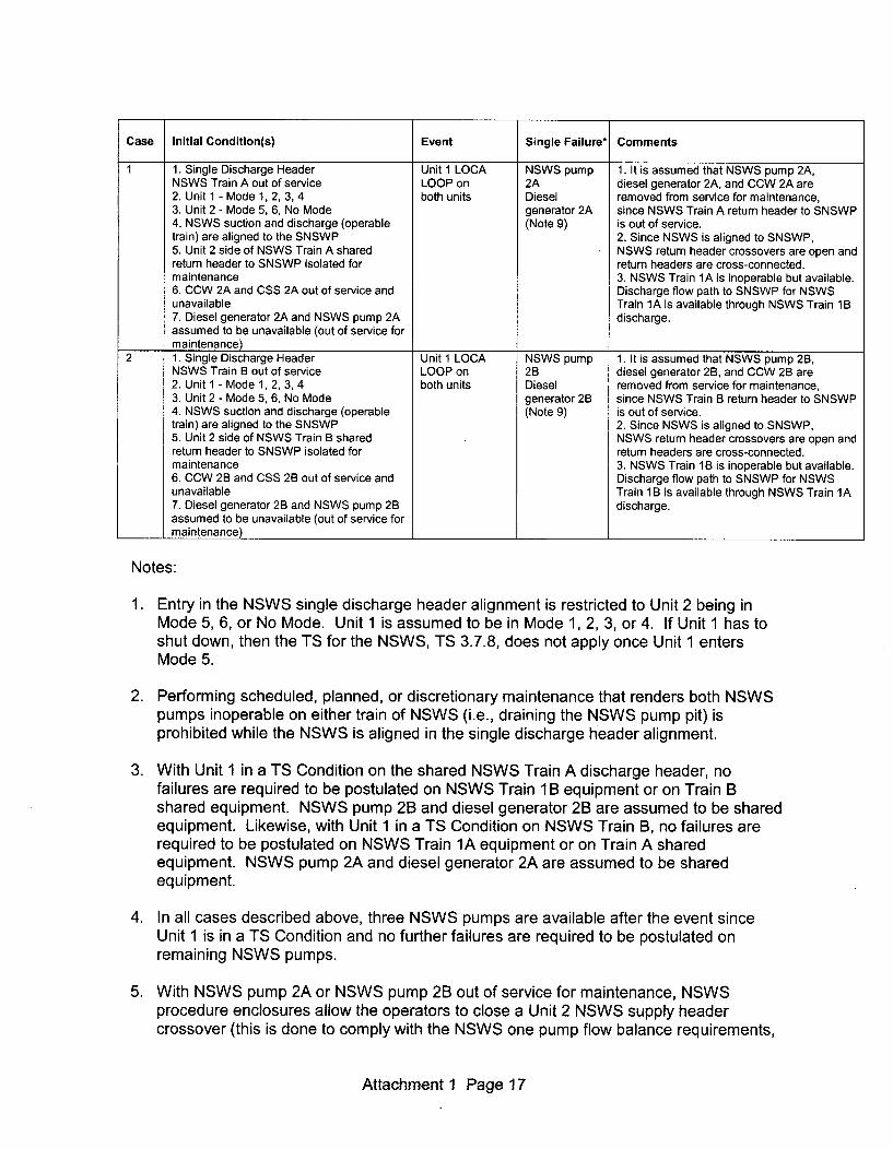
Case Initial Condition(s) Event Single Failure* Comments
1 1. Single Discharge Header Unit 1 LOCA NSWS pump 1. It is assumed that NSWS pump 2A,NSWS Train A out of service LOOP on 2A diesel generator 2A, and CCW 2A are2. Unit 1 - Mode 1, 2, 3, 4 both units Diesel removed from service for maintenance,3. Unit 2 - Mode 5, 6, No Mode generator 2A since NSWS Train A return header to SNSWP4. NSWS suction and discharge (operable (Note 9) is out of service.train) are aligned to the SNSWP 2. Since NSWS is aligned to SNSWP,5. Unit 2 side of NSWS Train A shared NSWS return header crossovers are open andreturn header to SNSWP isolated for return headers are cross-connected.maintenance 3. NSWS Train 1A is inoperable but available.6. CCW 2A and CSS 2A out of service and Discharge flow path to SNSWP for NSWSunavailable Train 1A is available through NSWS Train 1B7. Diesel generator 2A and NSWS pump 2A discharge.assumed to be unavailable (out of service formaintenance)
2 1. Single Discharge Header Unit 1 LOCA NSWS pump 1. It is assumed that NSWS pump 2B,NSWS Train B out of service LOOP on 2B diesel generator 2B, and CCW 2B are2. Unit 1 - Mode 1, 2, 3, 4 both units Diesel removed from service for maintenance,3. Unit 2 - Mode 5, 6, No Mode generator 2B since NSWS Train B return header to SNSWP4. NSWS suction and discharge (operable (Note 9) is out of service.train) are aligned to the SNSWP 2. Since NSWS is aligned to.SNSWP,5. Unit 2 side of NSWS Train B shared NSWS return header crossovers are open andreturn header to SNSWP isolated for return headers are cross-connected.maintenance 3. NSWS Train 1B is inoperable but available.6. CCW 2B and CSS 2B out of service and Discharge flow path to SNSWP for NSWSunavailable Train 1B is available through NSWS Train 1A7. Diesel generator 2B and NSWS pump 2B discharge.assumed to be unavailable (out of service formaintenance)
Notes:
1. Entry in the NSWS single discharge header alignment is restricted to Unit 2 being inMode 5, 6, or No Mode. Unit 1 is assumed to be in Mode 1, 2, 3, or 4. If Unit 1 has toshut down, then the TS for the NSWS, TS 3.7.8, does not apply once Unit 1 entersMode 5.
2. Performing scheduled, planned, or discretionary maintenance that renders both NSWSpumps inoperable on either train of NSWS (i.e., draining the NSWS pump pit) isprohibited while the NSWS is aligned in the single discharge header alignment.
3. With Unit 1 in a TS Condition on the shared NSWS Train A discharge header, nofailures are required to be postulated on NSWS Train 1 B equipment or on Train Bshared equipment. NSWS pump 2B and diesel generator 2B are assumed to be sharedequipment. Likewise, with Unit 1 in a TS Condition on NSWS Train B, no failures arerequired to be postulated on NSWS Train 1A equipment or on Train A sharedequipment. NSWS pump 2A and diesel generator 2A are assumed to be sharedequipment.
4. In all cases described above, three NSWS pumps are available after the event sinceUnit 1 is in a TS Condition and no further failures are required to be postulated onremaining NSWS pumps.
5. With NSWS pump 2A or NSWS pump 2B out of service for maintenance, NSWSprocedure enclosures allow the operators to close a Unit 2 NSWS supply headercrossover (this is done to comply with the NSWS one pump flow balance requirements,
Attachment 1 Page 17
since the NSWS one pump flow balance does not assume flow to the opposite trainNSWS essential headers). Unit 1 supply header crossovers close on a Sp signal. Thiscombination results in the Unit 1 and the Unit 2 supply crossover valves being closed,and therefore the NSWS supply headers have train separation. However, the returnheader crossovers are unaffected and remain open with power removed. Alternately,the operators may choose another procedure enclosure that does not close a Unit 2supply crossover with a Unit 2 NSWS pump out of service. In either case (NSWS Unit 2supply crossovers open or closed), adequate NSWS flow to essential components ismaintained.
6. With NSWS pump 2A or NSWS pump 2B out of service for maintenance, NSWSprocedure enclosures allow the operators to isolate the Unit 2 NSWS non-essentialheader (this is done to comply with the NSWS one pump flow balance requirements,since the NSWS one pump flow balance does not assume flow to the NSWS non-essential headers). However, the operators may choose another procedure enclosurethat does not isolate the Unit 2 non-essential header with a Unit 2 NSWS pump out ofservice. To eliminate the possibility of providing NSWS flow to the Unit 2 NSWS non-essential header, the NSWS single discharge header alignment will isolate the Unit 2non-essential header so that more NSWS flow is available for essential componentsserved by the NSWS. The Unit 1 non-essential header isolates on a Sp signal.Therefore, there is no NSWS flow to the Unit 1 NSWS non-essential header.
7. There is no NSWS flow to the CSS heat exchangers or Auxiliary Feedwater (AFW)makeup on the shutdown unit (Unit 2), since these are removed from service perprocedure and not required in the modes of applicability for this condition.
8. It should be noted that when the NSWS is aligned in the single discharge headeralignment that the NSWS return header crossovers will be open with power removedand therefore will not automatically close on a NSWS low-low pit level signal or on atransfer to the Auxiliary Shutdown Panels. This has a benefit of providing a flow path tothe Unit 1 NSWS train. This is allowable, since the three remaining NSWS pumps haveadequate capacity to supply the remaining cooling water demands of the three essentialheaders and three diesel generators. This has been demonstrated by the supportingsystems calculation.
9. The Unit 2 diesel generator and the NSWS pump on the affected train are out of service(these are considered the failures).
Attachment 1 Page 18

Case 1. NSWS Single Discharge Header Alignment - Train A Isolated - ConfigurationBefore and After Event
1. It is assumed that Unit 2 is Mode 5, 6, or No Mode; therefore, there is no Unit 2 TSCondition on the NSWS.
2. Unit 1 is in Mode 1, 2, 3, or 4.3. A portion (Unit 2 side) of the shared NSWS Train A discharge piping to the SNSWP
is isolated, resulting in a TS Condition on Unit 1.4. The 2A NSWS pump, 2A diesel generator, and 2A CCW System are assumed to be
out of service for maintenance and unavailable.5. Return header crossover valves 1 RN53B and 1 RN54A are open with power
removed and therefore will not automatically close on a NSWS low-low pit levelsignal or on a transfer to the Auxiliary Shutdown Panels. Unit 1 NSWS Train Acomponents can discharge through the NSWS Train 1 B discharge header, which isaligned to the SNSWP.
6. No failures are postulated on Train 1 B equipment or on Train B shared equipment,since Unit 1 is in a TS Condition on NSWS Train A.
7. NSWS Trains 1A, 1B, and 2B are aligned to discharge to the SNSWP. The LakeWylie discharge flow path is isolated since the NSWS is aligned (suction anddischarge) to the SNSWP.
Attachment 1 Page 19

2B Ný5 HX
ZiiX2RN229B
B Train A TrainTo To
1RN58BSp-O
Note 2
2A NSHX
2RN148A
U2 NonB Ess Hdr;
Train 1 RN55
2A KG)"HX
S1RN59
RN61
1RN63AClosed
ATrain
I 1RNP19 Aux YardBkdq
2B KC) -- :1HX
1RNP20 X, 1RN54A I
-1RN53B Note 1Note 1
IRNP181RN838
1B KC){,l I IA KCHX
HX [i11RN229B
1BNS HX
Isolated Piping:
L
L•1RN83iV
U1 Non) ]---Ess Hdr 1RN52B
Sp-K
1A NS HX Y-- • -1RN148A
1RN843B 1RN5TANote 3 Note 3
Shared Returnto Lake Wylie 4
Notes:
1. NSWS return header crossover valves are open with power removed and thereforewill not automatically close on a NSWS low-low suction pit level signal or on atransfer to the Auxiliary Shutdown Panels. Therefore, the NSWS return headersremain cross-connected and NSWS Train 1A has a discharge flow path availablethrough the NSWS Train 1 B return to the SNSWP.
2. NSWS return isolation to the SNSWP is open (power removed) with the NSWS inthe single discharge header alignment.
3. NSWS return isolation valves to Lake Wylie are closed.
Attachment 1 Page 20
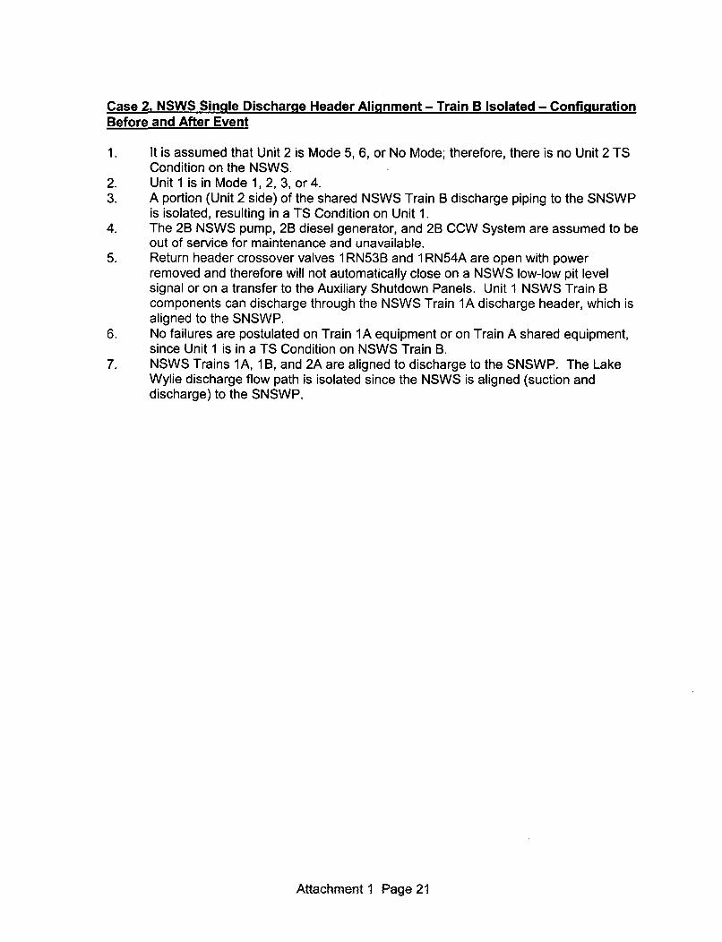
Case 2. NSWS Single Discharge Header Alignment - Train B Isolated - ConfigurationBefore and After Event
1. It is assumed that Unit 2 is Mode 5, 6, or No Mode; therefore, there is no Unit 2 TSCondition on the NSWS.
2. Unit 1 is in Mode 1, 2, 3, or 4.3. A portion (Unit 2 side) of the shared NSWS Train B discharge piping to the SNSWP
is isolated, resulting in a TS Condition on Unit 1.4. The 2B NSWS pump, 2B diesel generator, and 2B CCW System are assumed to be
out of service for maintenance and unavailable.5. Return header crossover valves 1 RN53B and 1 RN54A are open with power
removed and therefore will not automatically close on a NSWS low-low pit levelsignal or on a transfer to the Auxiliary Shutdown Panels. Unit 1 NSWS Train Bcomponents can discharge through the NSWS Train 1A discharge header, which isaligned to the SNSWP.
6. No failures are postulated on Train 1A equipment or on Train A shared equipment,since Unit 1 is in a TS Condition on NSWS Train B.
7. NSWS Trains 1A, 1B, and 2A are aligned to discharge to the SNSWP. The LakeWylie discharge flow path is isolated since the NSWS is aligned (suction anddischarge) to the SNSWP.
Attachment 1 Page 21

B Train A TrainTo To2Bfo HX
'2~1RN58B
RRN229B Closed
ED-
2ANSH 1 .RN63A2RN148Aj Sp-
Note 2
U2 Non~L_
B Ess HdS"V' 1Trai 1 RN55
2A KC)T\• T- AHX VN" Trai
1RN59
1 RN61 1RNP19 Aux Yard1RN61 \Rt'9BdKCI•I • ,•BIdql
2B KCHX
1RNP20 1RN54A
-11 RN53B Note 1H- Note 1
1RN838 1RNP8 1RN8372>1BCN[ 1AKCHX)------ Li
NXKC -1 I Ul Non )- ---
SRN229B ESS Hdr I RN52B|Sp-K 1
1B NS HX1A NS HX
1RN148A 41RN843B 1RN57A
Note3 Note 3
Isolated Piping:/
Shared Returnto Lake Wylie 4 . -
Notes:
1. NSWS return header crossover valves are open with power removed and thereforewill not automatically close on a NSWS low-low suction pit level signal or on atransfer to the Auxiliary Shutdown Panels. Therefore, the NSWS return headersremain cross-connected and NSWS Train 1 B has a discharge flow path availablethrough the NSWS Train 1A return to the SNSWP.
2. NSWS return isolation to the SNSWP is open (power removed) with the NSWS inthe single discharge header alignment.
3. NSWS return isolation valves to Lake Wylie are closed.
Attachment I Page 22

Conclusions
The justification provided in the supporting systems calculation for the NSWS singledischarge header alignment supports operation in this configuration, since Unit 1 will be in aTS Condition and no additional single failures are required to be postulated on Unit 1 or onshared equipment. However, this conclusion required that a PRA study be performed todetermine the additional risk associated with operation in this configuration for up to 14 daysand to determine if the alignment was acceptable from a PRA perspective.
With only one of the two NSWS return headers to the SNSWP in service while in the singledischarge header alignment, the NSWS cannot sustain an additional failure that affects theremaining NSWS discharge header to the SNSWP. This would include a NSWS piperupture or a NSWS valve failure that is in the active discharge flow path to the SNSWP. Tomitigate this risk, the NSWS single discharge header alignment has the NSWS pre-alignedto the SNSWP, and valves will be positioned with power removed. These measures havebeen incorporated into the PRA calculation that evaluated this alignment, and thiscalculation shows that the increase in risk associated with the NSWS being in the singledischarge header alignment is minimal and acceptable.
PRA Considerations
Duke Energy has used a risk-informed approach to determine the risk significance ofchanging the NSWS TS Completion Time beyond its current limit of 72 hours. Theacceptance guidelines given in Regulatory Guide (RG) 1.177, "An Approach for Plant-Specific, Risk-Informed Decisionmaking: Technical Specifications", were used todetermine the significance of this change.
The PRA analysis indicated that the risk acceptance criteria found in RG 1.177 for TSchanges were met with a proposed Completion Time of 14 days. The PRA model usedto perform this risk evaluation took into account previous modifications that allow thestation to operate all four NSWS pumps via a single train when a NSWS supply headeris removed from service.
Duke Energy initially performed a quality self assessment of the Catawba PRA againstRG 1.200, Rev. 1, "An Approach for Determining the Technical Adequacy ofProbabilistic Risk Assessment Results for Risk-Informed Activities". That assessmentindicated that 231 of the 306 Supporting Requirements (SRs) for Rev. 1 were fully met.In addition, 24 of the SRs were not applicable to Catawba at all, either because thereferenced techniques were not used in the PRA or because the SR was not requiredfor Capability Category (CC) I1. Of the remaining open SRs, only a small number wereof a technical nature. These are summarized as follows:
Attachment 1 Page 23
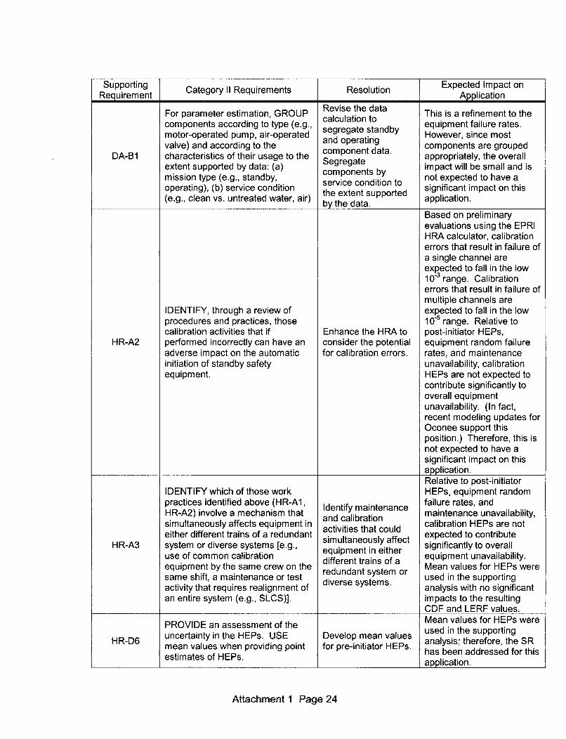
Supporting Category 11 Requirements Resolution Expected Impact onRequirement Application
For parameter estimation, GROUP Revise the data This is a refinement to thecomponents according to type (e.g., calculation to equipment failure rates.motor-operated pump, air-operated segregate standby However, since mostvalve) and according to the and operating components are grouped
DA-B1 characteristics of their usage to the component data. appropriately, the overallexetSegregate aporaey h vrlextentsupported by data: (a) co nents bimpact will be small and ismissintysupored (eg. datandby, components by not expected to have a
mission type (e.g., standby, sriecniint
operating), (b) service condition service condition to significant impact on this(e.g., clean vs. untreated water, air) the extent supported application.
by the data.Based on preliminaryevaluations using the EPRIHRA calculator, calibrationerrors that result in failure ofa single channel areexpected to fall in the low103 range. Calibrationerrors that result in failure ofmultiple channels are
IDENTIFY, through a review of expected to fall in the lowprocedures and practices, those 10-5 range. Relative tocalibration activities that if Enhance the HRA to post-initiator HEPs,
HR-A2 performed incorrectly can have an consider the potential equipment random failureadverse impact on the automatic for calibration errors. rates, and maintenanceinitiation of standby safety unavailability, calibrationequipment. HEPs are not expected to
contribute significantly tooverall equipmentunavailability. (In fact,recent modeling updates forOconee support thisposition.) Therefore, this isnot expected to have asignificant impact on thisapplication.Relative to post-initiator
IDENTIFY which of those work HEPs, equipment randompractices identified above (HR-Al, Identify maintenance failure rates, andHR-A2) involve a mechanism that maintenance unavailability,simultaneously affects equipment in activities that could calibration HEPs are noteither different trains of a redundant simultaneously affect expected to contribute
HR-A3 system or diverse systems [e.g., simultan ect significantly to overalluse of cmmon calbrationequipment in either eqimnuavlbltyuse of common calibration different trains of a equipment unavailability.equipment by the same crew on the redundant system or Mean values for HEPs weresame shift, a maintenance or test diverse systems. used in the supportingactivity that requires realignment of analysis with no significantan entire system (e.g., SLCS)]. impacts to the resulting
CDF and LERF values.
PROVIDE an assessment of the Mean values for HEPs were
HR-D6 uncertainty in the HEPs. USE Develop mean values used in the supportingmean values when providing point for pre-initiator HEPs. analysis; therefore, the SR
estimates of HEPs. has been addressed for thisI application.
Attachment 1 Page 24

Supporting Category 11 Requirements Resolution Expected Impact onRequirement Application
Characterize the uncertainty in the Mean values for HEPs wereestimates of the HEPs, and Develop mean values used in the supporting
HR-G9 PROVIDE mean values for use in for post-initiator analysis; therefore, thisthe quantification of the PRA HEPs. issue has been addressedresults. for this application.
This item is relevant to
Give theexpeted applications that includeFor each flood area not screened Given the expected ofninternal flood initiators.out using the requirements under flood areas needed to Whereas the cut setsIF-Bib, IDENTIFY the SSCs located satisfy requirement generated for thisin each defined flood area and IF- IF-Ay, additional application include anA2 along flood propagation paths IAaitiol internal flooding event, itthat are modeled in the internal equipment will need does not dominate theevents PRA model as being dentified and results (see section belowrequired to respond to an initiating discussed in order to entitled "Internal/Externalevent or whose failure would Floods PRA which
IF-C2c challenge normal plant operation, requirements of the confirms no significant
and are susceptible to flood. For impact from internaleach identified SSC, IDENTIFY, for current flooding flooding events).the purpose of determining its analysis does not Therefore, this item is notsusceptibility per IF-C3, its spatial discuss flood expected to have alocation in the area and any mithis will have to significant impact on thisflooding mitigative features (e.g., be corrected to satisfy application. (An update toshielding, flood, or spray capability the requirements of the Catawba internalratings). the ASmentsnof.flooding analysis to meet
the ASME Standard. RG 1.200 Rev. 2 is plannedfor completion in 2011.)This item is relevant toapplications that includeinternal flood initiators. The
The current flooding lone significant internalanalysis identifies the flooding event found in the
For the SSCs identified in IF-C2c, submergence failure cut sets generated for thisIDENTIFY the susceptibility of each height of the application involves theSSC in a flood area to flood- equipment important Auxiliary Shutdown Panel.induced failure mechanisms. to accident mitigation, However, this event doesINCLUDE failure by submergence but, except for the not dominate the resultsand spray in the identification Auxiliary Shutdown (see section below entitled
IF-C3 process. ASSESS qualitatively the Panel, never "Internal/External Floodsimpact of flood-induced addresses the impact PRA" which confirms nomechanisms that are not formally of spray. Spray as a significant impact fromaddressed (e.g., using the failure mechanism internal flooding events).mechanisms listed under Capability needs to be Therefore, this item is notCategory 111 of this requirement), addressed in the expected to have aby using conservative assumptions. analysis or a note significant impact on this
made explaining why application. (An update toit was omitted. the Catawba internal
flooding analysis to meetRG 1.200 Rev. 2 is plannedfor completion in 2011.)
Attachment 1 Page 25

Supporting Category '1 Requirements Resolution Expected Impact onRequirement Application
This item is relevant toapplications that includeinternal flood initiators.Whereas the cut sets
IDENTIFY inter-area propagation generated for thisthrough the normal flow path from application include anone area to another via drain lines; Provide more analysis internal flooding event, itand areas connected via back flow of flood propagation does not dominate thethrough drain lines involving failed flowresults (see section belowcheck valves, pipe, and cable potential structural entitled "Internal/External
IF-C3b penetrations (including cable trays), failure of doors or Floods PRA" whichdoors, stairwells, hatchways, and walls due to flooding confirms no significant
HVAC ducts. INCLUDE potential loads and the impact from internalfor structural failure (e.g., of doors potential for barrier flooding events).or walls) due to flooding loads and unavailability. Therefore, this item is notthe potential for barrier expected to have aunavailability, including significant impact on thismaintenance activities. application. (An update to
the Catawba internalflooding analysis to meetRG 1.200 Rev. 2 is plannedfor completion in 2011.)This item is relevant toapplications that includeinternal flood initiators.Whereas the cut setsgenerated for thisapplication include aninternal flooding event, it
INCLUDE, in the quantification, does not dominate theboth the direct effects of the flood results (see section below(e.g., loss of cooling from a service entitled "Internal/External
IF.E6b water train due to an associated Address potential Floods PRA" whichpipe rupture) and indirect effects indirect effects. confirms no significantsuch as submergence, jet impact from internalimpingement, and pipe whip, as flooding events).applicable. Therefore, this item is not
expected to have asignificant impact on thisapplication. (An update tothe Catawba internalflooding analysis to meetRG 1.200 Rev. 2 is plannedfor completion in 2011.)This issue affects somesmall LOCAs. Because the
In crediting HFEs that support the Explicitly model RCS small LOCA contribution toaccident progression analysis, USE depressurization for Large Early ReleaseLE- thac pliciden p ressionanays, UE small LOCAs and Frequency (LERF) is small,
LE-C6 the applicable requirements of pefrthnomeiaipctwudbparagraph 4.5.5, as appropriate for perform the no material impact would beparagrap 4.ve 5 o aslofthe approriat f dependency analysis expected. Therefore, thisthe level of detail of the analysis. on the HEPs. item is not expected to have
a significant impact on thisapplication.
Attachment 1 Page 26

The remaining open SRs required enhanced documentation but none was expected tohave a significant impact on the PRA results or insights. Based on this assessment, theinternal events portion of the Catawba PRA fully satisfies all of the configuration andcontrol requirements for meeting Rev. 1 of RG 1.200.
Per Section 4.2 of RG 1.200, Rev. 2, an assessment is required for permanent plantchanges that have an impact on the PRA model but have not been incorporated.Outstanding changes to be incorporated in future PRA updates are recorded andevaluated per PRA Workplace Procedure XSAA-1 06, "Workplace Procedure for PRAMaintenance, Update and Application". These events are captured and tracked via anin-house PRA database, "PRA Tracker". Based upon criteria set in XSAA-106, plantchanges affecting the PRA model are classified as either "high", "medium", or "low" risk.The resolution of all "high" and "medium" risk items, as well as all applicable "low" riskitems, is assessed below:
Tracker Item Risk Description/EvaluationNo.
Station modification CD500063 adds new manual valves to theNSWS Discharge Header. The manual valves will normally belocked open. Consider adding these valves to the NSWSmodel.
0-05-0017 Low These valves were added to both the Loss of NSWS and main
fault trees. Adding these valves makes an insignificantcontribution to the Loss of NSWS risk as well as to the overallrisk results.
C-03-01163 adds NSWS cross connect piping and valves toallow a single NSWS header to supply the cooling water to bothtrains of the diesel generators. Other miscellaneous changesalso to fire hose racks and diesel generator starting air supply
C-05-0019 Low piping.
These modifications have been made to the NSWS and areincluded in the revised fault tree model used to support thisanalysis.Install 30-inch crossover NSWS line in Auxiliary Building toallow single header operation (as a replacement for the existing20-inch crossover). Also, modification CD200358 needs to bereviewed with this package as it also has other NSWS piping
C-05-0027 Low changes. Unit 1 modification package is CD100139.
These modifications have been made to the NSWS and arereflected in the revised fault tree model used to support thisanalysis.Modifications to the NSWS headers to add crossovers betweendiesel generators. CD100106 adds crossovers too. Also,CD500062 upgrades NSWS pump strainer discharge piping tosupport a cross tie to be installed under modification CD500091.
C-06-0004 LowPer the change form evaluation, the modifications are expectedto be mostly editorial and will result in an improvement in CoreDamage Frequency (CDF); therefore, there are no expected
I I impacts that would alter the results of this analysis.
Attachment 1 Page 27
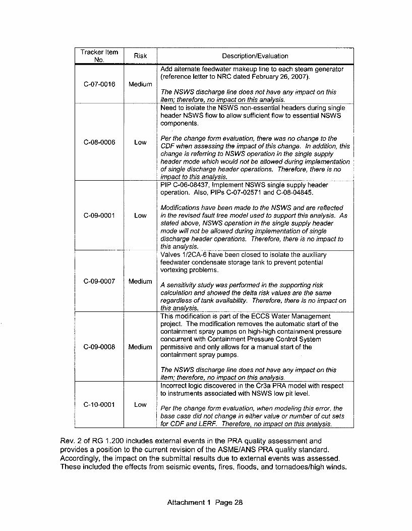
Tracker Item Risk Description/EvaluationNo.
Add alternate feedwater makeup line to each steam generator(reference letter to NRC dated February 26, 2007).
C-07-0016 MediumThe NSWS discharge line does not have any impact on thisitem; therefore, no impact on this analysis.Need to isolate the NSWS non-essential headers during singleheader NSWS flow to allow sufficient flow to essential NSWScomponents.
Per the change form evaluation, there was no change to theCDF when assessing the impact of this change. In addition, this
change is referring to NSWS operation in the single supplyheader mode which would not be allowed during implementationof single discharge header operations. Therefore, there is noimpact to this analysis.PIP C-06-08437, Implement NSWS single supply headeroperation. Also, PIPs C-07-02571 and C-08-04845.
Modifications have been made to the NSWS and are reflectedC-09-0001 Low in the revised fault tree model used to support this analysis. As
stated above, NSWS operation in the single supply headermode will not be allowed during implementation of singledischarge header operations. Therefore, there is no impact tothis analysis.Valves 1/2CA-6 have been closed to isolate the auxiliaryfeedwater condensate storage tank to prevent potentialvortexing problems.
0-09-0007 Medium A sensitivity study was performed in the supporting risk
calculation and showed the delta risk values are the sameregardless of tank availability. Therefore, there is no impact onthis analysis.This modification is part of the ECCS Water Managementproject. The modification removes the automatic start of thecontainment spray pumps on high-high containment pressureconcurrent with Containment Pressure Control System
C-09-0008 Medium permissive and only allows for a manual start of thecontainment spray pumps.
The NSWS discharge line does not have any impact on thisitem; therefore, no impact on this analysis.Incorrect logic discovered in the Cr3a PRA model with respectto instruments associated with NSWS low pit level.
0-10-0001 Low Per the change form evaluation, when modeling this error, the
base case did not change in either value or number of cut setsfor CDF and LERF. Therefore, no impact on this analysis.
Rev. 2 of RG 1.200 includes external events in the PRA quality assessment andprovides a position to the current revision of the ASME/ANS PRA quality standard.Accordingly, the impact on the submittal results due to external events was assessed.These included the effects from seismic events, fires, floods, and tornadoes/high winds.
Attachment 1 Page 28

Seismic PRA
The current Catawba seismic PRA model of record was last updated as part of Revision3 of the PRA model. The current methodology used is the same as that described indetail in the Individual Plant Examination (IPE) submittal and in Section 3 of theIndividual Plant Examination for External Events (IPEEE) submittal, both of which havealready been reviewed by the NRC.
The current seismic PRA contains the technical elements given in Section 1.2.6 of RG1.200, Rev. 2 as part of the methodology referenced above. A site-specific seismichazard analysis was performed for Catawba and is documented in EPRI Report RP1 01-53, "Probabilistic Seismic Hazard Evaluation for Catawba Nuclear Station". This hazardwas used to develop the analyses discussed above for the IPE, IPEEE, and currentseismic model. Furthermore, Duke Energy has been actively following developmentsrelated to GI-199, "Implications of Updated Probabilistic Seismic Hazard Estimates inCentral and Eastern United States". In 2008, Risk Engineering Inc. performedpreliminary comparisons of the EPRI 2008 seismic hazards and EPRI 1989 seismichazards for the Duke Energy plants. Their results indicated no significant impact toCatawba.
A seismic fragility analysis was also performed as part of the seismic PRA development.Median fragilities were developed for risk-important components and structures, alongwith their corresponding randomness and uncertainty factors. These values were usedin the IPE and IPEEE analyses, as well as in the current seismic PRA model.
The seismic plant response is determined using a fault tree comprised of a combinationof several random events from the plant internal events tree in conjunction with eventsrepresenting the median fragilities of plant equipment and structures. The resultingaccident sequences (cut sets) are then evaluated against the plant seismicity curvesand the median fragilities using a Monte Carlo analysis which determines theseismically-induced CDF.
Components with median seismic capacities in excess of 2g are screened out of theseismic fault tree model due to their low probability of failure. Likewise, structures areeliminated from consideration when their seismic capacities are in excess of 2.5g.Among those components and structures screened out were the SNSWP dam, theNSWS pumps, and all qualified piping and valves. Therefore, the NSWS componentsand piping are considered to be seismically rugged. Since the NSWS components andstructures were screened out of the model, a sensitivity study was performed toconservatively bound the impact of having a NSWS discharge line unavailable during aseismic event. The seismic CDF showed only a modest increase using veryconservative bounding assumptions. In addition, there were no new failure modesintroduced and consideration of the seismic impact is thus not a factor for thisassessment.
In accordance with the discussion in this section and the results of the boundinganalysis above, Duke Energy considers inclusion of seismic results as insignificant tothe overall results. Therefore, it is judged that the analyses assessing the influence ofseismic events provide an acceptable evaluation of the contribution of the seismic riskfor the requested Completion Time of 14 days.
Attachment 1 Page 29

Internal Fire PRA
The current Catawba fire PRA model analysis and methodology used in the model ofrecord is the same analysis and methodology as described in the IPE submittal, Section4 and Appendix B of the IPEEE submittal, and as discussed in the Supplemental IPEEEFire Analysis Report (letter from Duke Power Company to NRC, "Supplemental IPEEEReport", McGuire Nuclear Station and Catawba Nuclear Station, dated July 30, 1996),all of which have already been reviewed by the NRC.
The plant-specific fire PRA analysis consists of four steps, each of which is describedbelow:
" The Catawba site and plant areas were analyzed to determine critical fire areasand possible scenarios for the possibility of a fire causing one or more of apredetermined set of initiating events. Screening criteria were defined for thosefire areas excluded from the fire analysis.
" If there was a potential for an initiating event to be caused by a fire in an area,then the area was analyzed for the possibility of a fire causing other events whichwould impact the ability to shut down the plant. These were identified by reviewingthe impact on the internal events analysis models.Each area was examined with an event tree fire model to quantify fire damageprobabilities. The event tree related fire initiation, detection, suppression, andpropagation probabilities to equipment damage states.Fire sequences were derived and quantified based on the fire damage probabilitiesand the additional failures necessary for a sequence to lead to a core melt. Theadditional failures were quantified by the models used in the internal eventsanalysis.
The major changes to the current fire analysis that have been made since the IPEEEsubmittal deal with implementation of changes from the Supplemental IPEEE FireAnalysis Report and revised base case fire initiating event frequencies.
The Catawba fire PRA model is integrated into the overall PRA model; therefore,quantitative fire risk insights can be obtained for this submittal. Internal fire eventscontribute approximately 10% of the CDF and 3% of the LERF. Whereas fire-inducedloss of NSWS events are included in the PRA model, they do not appear in any coredamage or large early release sequences (above the respective truncation limits).Furthermore, in comparing the delta risk cut sets created in support of the submittalanalysis (i.e., those cut sets whose values showed an increase in the submittalconfiguration when compared to their values in the "base case" configuration), nointernal fire sequences of any type appear in the core damage and large early releaseresults. Therefore, the contribution from fire events for the submittal configurationimpacting the NSWS is negligible.
Finally, consider that the NSWS essential header discharge valves and the dischargevalve to the SNSWP will remain open during the requested 14 day Completion Timewith power removed. Therefore, fire events affecting power to these valves cannotcause their spurious operation and thus have no effect on the NSWS dischargealignment during the Completion Time.
Attachment 1 Page 30

Given the negligible influence of fires on the NSWS for the submittal configuration (i.e.,no dominant contribution from fires), it is judged that the analyses assessing theinfluence of internal fire events provide an acceptable evaluation of the contribution ofthe fire risk for the requested Completion Time of 14 days.
Internal/External Floods PRA
Flooding events at Catawba have been assessed via the IPE process and are noted inSections 3.3.5 and 3.4 of the IPE. Internal flooding events are primarily caused by plantpiping ruptures while external floods are mostly caused by very heavy precipitationevents. The external events portion is recreated in Section 5.2 of the IPEEE report. Asmentioned above, the IPE and IPEEE submittals have already been reviewed by theNRC.
Flood levels for the site were analyzed for the following flood-producing phenomena:
* Probable Maximum Flood (PMF) resulting from the Probable MaximumPrecipitation (PMP) positioned appropriately over the Catawba River Basin.
* PMF resulting from the PMP positioned appropriately over the tributary area of theSNSWP.
* Standard Project Flood (SPF) passing through Lake Wylie (positioned over eachCatawba River Basin drainage area) combined with the failure of one of theupstream dams because of an Operating Basis Earthquake (OBE). The SPF isconsidered equal to one-half of the PMF.
* Surge and seiche effects caused by probable maximum hurricane.
" Coincident wave runup due to a 40 mph wind.
* Local intense precipitation (PMP) occurring over the immediate project site.
In the IPEEE report, it was concluded that the contribution to plant risk from external
flooding would be insignificant compared to the risk from internal flooding.
The plant-specific Catawba internal flooding analysis was performed in six steps:
* Identification of the critical flood areas.
" Calculation of flood rates.
* Development of flood probabilities.
" Identification of critical flood levels.
* Assessment of human response for flood isolation.
• Development and quantification of the flood core damage cut sets.
The major change made to the current internal flood analysis since the IPE and IPEEEsubmittals was the installation of concrete flood walls in the Turbine Building basementto protect essential 4160 VAC switchgear against large flooding events. As a result,
Attachment 1 Page 31

flooding initiator probabilities which would result in either a reactor trip or a loss of thetransformers have been significantly reduced.
As with the fire analysis, the Catawba internal flooding PRA model is integrated into theoverall PRA model; therefore, quantitative flood risk insights can be obtained for thesubmittal. The applicable cut sets were reviewed to determine the contribution level ofthe flooding initiating events. Internal flooding events comprise approximately 2% of theCDF and < 1% of the LERF. The majority of this contribution comes from a floodingevent in the Auxiliary Building which results in a loss of the Auxiliary Shutdown Panel.
As indicated previously, the NSWS discharge piping associated with this submittalresides in the Auxiliary Building; thus, it could be postulated that this area could be moresusceptible to flooding risk during the Completion Time. Per guidance provided in DukeEnergy's risk configuration management Nuclear System Directives for both at powerand shutdown conditions, the station is required to give consideration to plantconfigurations which could potentially cause internal flood hazards resulting in a failureof risk significant structures, systems, and components. Furthermore, per the failureanalysis of the NSWS butterfly valves used in the NSWS single discharge headeralignment, "[t]he manual and motor operated valves installed in this portion of the NSWsystem are Fisher Posi-Seal butterfly valves. When these valves are closed, there isnot a credible failure that would cause them to change position or catastrophically comeapart." In the closed position, the operator gearbox will hold the valve disc still. Thegearbox operators are manufactured by Limitorque and have locking gear sets that willnot move even during a seismic event. Therefore, exposing the isolated NSWSdischarge piping during the 14 day Completion Time is considered to have a negligibleimpact on flooding risk in the Auxiliary Building. As a sensitivity study, the value for theAuxiliary Building flood initiator in the PRA model was increased by its error factor (7.5)from 5.5E-06 to 4.13E-05. As a result, the CDF for the Completion Time configurationincreased by only 9.8% and the corresponding LERF increased only 2.2%. Thus, theimpact on internal flooding is considered insignificant.
Given the negligible influence of flooding events for the submittal configuration, it isjudged that the analyses assessing the influence of these events provide an acceptableevaluation of the contribution of the flood risk for the requested Completion Time of 14days.
Tornado/High Winds PRA
As with earthquakes, fires, and floods, an assessment for tornadoes and other highwind events at Catawba has been performed via the IPE process as well as with theIPEEE process. The Catawba tornado analysis was developed in the following steps:
" The effects of tornado missiles and high winds on the plant were determined." An event tree was constructed which mapped out possible sequences of events
following a tornado strike." The sequences were quantified using detailed fault trees to model the event tree.
A wind hazard analysis was developed that reflects available regional and site-specificinformation. A Monte Carlo simulation was performed to evaluate the effects of tornado
Attachment 1 Page 32

missiles on the targets of interest. Inputs to the plant model include plant structuraldesign data and possible missiles located onsite.
The Catawba tornado PRA model is also integrated into the overall PRA model;therefore, quantitative tornado risk insights can be obtained for the submittal. The cutsets generated for the submittal analysis were reviewed to determine the contributionlevel of the tornado-initiating events. Only one event (Tornado Causes a Loss of OffsitePower) contributed to the CDF (- 3%) and the LERF (- 4%). Typically, these cut setsinclude a loss of the diesel generators and either auxiliary feedwater or the StandbyShutdown System. A review of the delta risk cut sets created in support of the submittalanalysis found that, while tornado events were a significant contributor to theIncremental Conditional Core Damage Probability (ICCDP) and Incremental ConditionalLarge Early Release Probability (ICLERP), this contribution comes from the increasedtornado frequency value ("seasonal factor") used in the risk assessment to account forhistoric increased tornado activity during the months of March, April, and May, ratherthan from interactions with the NSWS configuration.
Furthermore, even though the NSWS provides cooling to the diesel generators, as wellas serving as the assured source of auxiliary feedwater, functionality of the NSWSfollowing a tornado event is governed by the operability of the diesel generators andwould not be altered per the configuration found in the 14 day Completion Time.Therefore, the impact of tornadoes and high wind events is negligible.
Given the negligible influence of tornado and high wind events on the NSWS for thesubmittal configuration (i.e., no dominant contribution from tornadoes/high winds), it isjudged that the analyses assessing the influence of these events provide an acceptableevaluation of the contribution of the tornado and high wind risk for the requestedCompletion Time of 14 days.
In conclusion, it is recognized that the PRA models do not meet all of the supportingrequirements of Capability Category II of ASME/ANS PRA Standard RA-Sa-2009.However, not all risk-informed applications need to meet CC II. Nevertheless, DukeEnergy has evaluated the applicable SRs not meeting CC II to the CC II standard andhas determined that they do not have a significant impact on this application. Therefore,Duke Energy considers the Catawba PRA models used to assess the risk impact assufficient to support the requested 14 day Completion Time.
Attachment 1 Page 33

5. REGULATORY EVALUATION
5.1 Applicable Regulatory Requirements/Criteria
Discussion of GDC Requirements
This discussion is contained in Section 4 of this submittal.
5.2 Precedent
The NRC approved a comparable license amendment request to allow singlesupply header operation of the NSWS for Catawba via Amendments 243/237 onJuly 30, 2008 (CATAWBA NUCLEAR STATION, UNITS 1 AND 2, ISSUANCEOF AMENDMENTS REGARDING SINGLE SUPPLY HEADER OPERATION OFTHE BURIED NUCLEAR SERVICE WATER SYSTEM (TAC NOS. MD6275 ANDMD6276)) ADAMS Accession Number ML081980769. The approvedamendments reference all of the Duke Energy correspondence associated withthis license amendment request. This correspondence included the following:
Initial submittal dated July 30, 2007 (ADAMS Accession Number ML072640193)
Response to request for additional information dated May 27, 2008 (ADAMSAccession Number ML081510801)
Response to request for additional information dated June 23, 2008 (ADAMSAccession Number ML081770060)
5.3 No Significant Hazards Consideration
The following discussion is a summary of the evaluation of the changescontained in this proposed amendment against the 10 CFR 50.92(c)requirements to demonstrate that all three standards are satisfied. A nosignificant hazards consideration is indicated if operation of the facility inaccordance with the proposed amendment would not:
1. Involve a significant increase in the probability or consequences of anaccident previously evaluated, or
2. Create the possibility of a new or different kind of accident from anyaccident previously evaluated, or
3. Involve a significant reduction in a margin of safety.
First Standard
Does operation of the facility in accordance with the proposed amendmentinvolve a significant increase in the probability or consequences of an accidentpreviously evaluated?
Response: No.
Attachment 1 Page 34

The proposed single discharge header operation configuration for NSWSoperation and the associated proposed TS and Bases changes have beenevaluated to assess their impact on plant operation and to ensure that the designbasis safety functions of safety related systems are not adversely impacted.During single discharge header operation, the operating NSWS header will beable to discharge all required NSWS flow from safety related components. PRAhas demonstrated that due to the limited proposed time in the single dischargeheader configuration, the resultant plant risk remains acceptable.
The purpose of this amendment request is to ultimately facilitate inspection andmaintenance of the Unit 2 NSWS discharge headers within the Auxiliary Building.Therefore, NRC approval of this request will ultimately help to enhance the long-term structural integrity of the NSWS and will help to ensure the system'sreliability for many years.
In general, the NSWS serves as an accident mitigation system and cannot byitself initiate an accident or transient situation. The only exception is that theNSWS piping can serve as a source of floodwater to safety related equipment inthe Auxiliary Building or in the diesel generator buildings in the event of a leak ora break in the system piping. The probability of such an event is not significantlyincreased as a result of this proposed request. Safety related NSWS piping istested and inspected in accordance with all applicable inservice testing andinservice inspection requirements. Given the negligible influence of floodingevents on the NSWS for the submittal configuration (i.e., no dominantcontribution from floods), it is judged that the analyses assessing the influence ofthese events provide an acceptable evaluation of the contribution of the floodrisk for the requested Completion Time of 14 days.
The proposed 14 day TS Required Action Completion Time has been evaluatedfor risk significance and the results of this evaluation have been foundacceptable. The probabilities of occurrence of accidents presented in theUFSAR will not increase as a result of implementation of this change. Becausethe PRA analysis supporting the proposed change yielded acceptable results,the NSWS will maintain its required availability in response to accident situations.Since NSWS availability is maintained, the response of the plant to accidentsituations will remain acceptable and the consequences of accidents presentedin the UFSAR will not increase.
Second Standard
Does operation of the facility in accordance with the proposed amendmentcreate the possibility of a new or different kind of accident from any accidentpreviously evaluated?
Response: No.
Implementation of this amendment will not create the possibility of a new ordifferent kind of accident from any accident previously evaluated. The proposedrequest does not affect the basic operation of the NSWS or any of the systems
Attachment I Page 35

that it supports. These include the Emergency Core Cooling System, theContainment Spray System, the Containment Valve Injection Water System, theAuxiliary Feedwater System, the Component Cooling Water System, the ControlRoom Area Ventilation System, the Control Room Area Chilled Water System,the Auxiliary Building Filtered Ventilation Exhaust System, or the DieselGenerators. During proposed single discharge header operation, the NSWS willremain capable of fulfilling all of its design basis requirements.
No new accident causal mechanisms are created as a result of NRC approval ofthis amendment request. No changes are being made to the plant which willintroduce any new type of accident outside those assumed in the UFSAR.
Third Standard
Does operation of the facility in accordance with the proposed amendmentinvolve a significant reduction in the margin of safety?
Response: No.
Implementation of this amendment will not involve a significant reduction in anymargin of safety. Margin of safety is related to the confidence in the ability of thefission product barriers to perform their design functions during and following anaccident situation. These barriers include the fuel cladding, the reactor coolantsystem, and the containment system. The performance of these fission productbarriers will not be impacted by implementation of this proposed TS amendment.During single discharge header operation, the NSWS and its supported systemswill remain capable of performing their required functions. No safety margins willbe impacted.
The PRA conducted for this proposed amendment demonstrated that the impacton overall plant risk remains acceptable during single discharge headeroperation. Therefore, there is not a significant reduction in the margin of safety.
Based upon the preceding discussion, Duke Energy has concluded that theproposed amendment does not involve a significant hazards consideration.
5.4 Conclusions
In conclusion, based on the considerations discussed above, (1) there isreasonable assurance that the health and safety of the public will not beendangered by operation in the proposed manner, (2) such activities will beconducted in compliance with the Commission's regulations, and (3) theissuance of the amendment will not be inimical to the common defense andsecurity or to the health and safety of the public.
Attachment I Page 36

6. ENVIRONMENTAL CONSIDERATION
Pursuant to 10 CFR 51.22(b), an evaluation of this license amendment request hasbeen performed to determine whether or not it meets the criteria for categoricalexclusion set forth in 10 CFR 51.22(c)(9) of the regulations.
Implementation of this amendment will have no adverse impact upon the Catawba units;neither will it contribute to any additional quantity or type of effluent being available foradverse environmental impact or personnel exposure.
It has been determined there is:
1. No significant hazards consideration,
2. No significant change in the types, or significant increase in the amounts, of anyeffluents that may be released offsite, and
3. No significant increase in individual or cumulative occupational radiationexposures involved.
Therefore, this amendment to the Catawba TS meets the criteria of 10 CFR 51.22(c)(9)for categorical exclusion from an environmental impact statement.
Attachment 1 Page 37

7. REFERENCES
7.1 Letter from John Stang, NRC to J.R. Morris, Duke Energy, "CATAWBANUCLEAR STATION, UNITS 1 AND 2, ISSUANCE OF AMENDMENTSREGARDING SINGLE SUPPLY HEADER OPERATION OF THEBURIED NUCLEAR SERVICE WATER SYSTEM (TAC NOS. MD6275AND MD6276)", July 30, 2008, ADAMS Accession NumberML081980769.
Attachment I Page 38

ATTACHMENT 2
MARKED UP TS PAGES

Inserts for TS 3.7.8 and TSB 3.7.8
INSERT 1
C. ----------- NOTES -----......
1. Entry into this Conditionshall only be allowed forUnit 1 and for pre-plannedactivities as described inthe Bases of thisSpecification.
2. Immediately enterCondition A of this LCO ifone or more Unit 1required NSWScomponents becomeinoperable while in thisCondition and one NSWStrain remainsOPERABLE.
3. Immediately enter LCO3.0.3 if one or more Unit1 required NSWScomponents becomeinoperable while in thisCondition and no NSWStrain remainsOPERABLE.
One NSWS Auxiliary Buildingdischarge header inoperabledue to NSWS being alignedfor single Auxiliary Buildingdischarge header operation.
C.1 Restore NSWS Auxiliary Buildingdischarge header to OPERABLEstatus.
14 days

INSERT 2
While the NSWS is operating in the single discharge header alignment, one of the Unit 2 discharge headers isremoved from service in support of planned maintenance or modification activities associated with the dischargeheader that is taken out of service. In this configuration, each NSWS train is considered OPERABLE with therequired NSWS flow to safety related equipment being discharged through the remaining OPERABLE NSWSdischarge header. While the NSWS is operating in the single discharge header alignment, an NSWS train isconsidered OPERABLE during MODES 1, 2, 3, and 4 when:
a. The associated train related NSWS pumps are OPERABLE (except that for the discharge header that it removedfrom service, its associated train related NSWS pump may also be removed from service); and
b. The associated piping (except for the discharge header that is taken out of service), valves, and instrumentationand controls required to perform the safety related function are OPERABLE.
Operation of the NSWS in the single supply header alignment and the single discharge header alignment at the sametime is prohibited.
INSERT 3
C.1
If one NSWS Auxiliary Building discharge header is inoperable due to the NSWS being aligned for single AuxiliaryBuilding discharge header operation, the NSWS Auxiliary Building discharge header must be restored to OPERABLEstatus within 14 days. Dual Auxiliary Building discharge header operation is the normal alignment of the NSWS. TheCompletion Time of 14 days is supported by probabilistic risk analysis. While in Condition C, the single AuxiliaryBuilding discharge header is adequate to perform the heat removal function for all required safety related equipmentfor its respective safety train. Due to the design of the NSWS, only the operating unit is required to enter thisCondition when the NSWS is aligned for single Auxiliary Building discharge header operation. Pre-planned activitiesrequiring entry into this Condition are only performed with Unit 2 in an outage (MODE 5, 6, or No MODE).
Condition C is modified by three Notes. Note 1 states that entry into this Condition shall only be allowed for Unit 1and for pre-planned activities as described in the Bases of this Specification. Condition C is only allowed to beentered in support of planned maintenance or modification activities associated with the Auxiliary Building dischargeheader that is taken out of service. An example of a situation for which entry into this Condition is allowed isrefurbishment of an Auxiliary Building discharge header. Entry into this Condition is not allowed in response tounplanned events or for other events involving the NSWS. Examples of situations for which entry into this Conditionis prohibited are emergent repair of discovered piping leaks and other component failures. For unplanned events orother events involving the NSWS, Condition A must be entered. Note 2 requires immediate entry into Condition A ofthis LCO if one or more Unit 1 required NSWS components become inoperable while in this Condition and oneNSWS train remains OPERABLE. With one remaining OPERABLE NSWS train, the NSWS can still perform itssafety related function. However, with one inoperable NSWS train, the NSWS cannot be assured of performing itssafety related function in the event of a single failure of another NSWS component. While the loss of any NSWScomponent subject to the requirements of this LCO can result in the entry into Condition A, the most commonexample is the inoperability of an NSWS pump. This occurs during periodic testing of the emergency dieselgenerators. Inoperability of an emergency diesel generator renders its associated NSWS pump inoperable. Note 3requires immediate entry into LCO 3.0.3 if one or more Unit 1 required NSWS components become inoperable whilein this Condition and no NSWS train remains OPERABLE. In this case, the NSWS cannot perform its safety relatedfunction.

INSERT 4
or if the NSWS Auxiliary Building discharge header cannot be restored to OPERABLE status within the associatedCompletion Time,

NSWS
THIS PAGE 3.7.8r OR I •i'ý- 3 A•T "3, ";•Y
3.7 PLANT SYSTEMS
3.7.8 Nuclear Service Water System (NSWS)
LCO 3.7.8
APPLICABILITY:
Two NSWS trains shall be OPERABLE.
MODES 1, 2, 3, and 4.
I
ACTIONS
CONDITION REQUIRED ACTION COMPLETION TIME
A. One NSWS train A.1 --------- NOTES------inoperable. 1. Enter applicable
Conditions andRequired Actions ofLCO 3.8.1, "ACSources-Operating," foremergency dieselgenerator madeinoperable by NSWS.
2. Enter applicableConditions andRequired Actions ofLCO 3.4.6, "RCSLoops-MODE 4," forresidual heat removalloops madeinoperable by NSWS.
Restore NSWS train to 72 hours
OPERABLE status.
(continued)
I
Catawba Units 1 and 2 3.7.8-1 Amendment Nos. 243/237

NSWS3.7.8
ACTIONS (continued)
CONDITION REQUIRED ACTION COMPLETION TIME
B. -------- NOTES------1. Entry into this
Condition shall onlybe allowed for pre-planned activities asdescribed in theBases of thisSpecification.
2. Immediately enterCondition A of thisLCO if one or moreNSWS componentsbecome inoperablewhile in thisCondition and oneNSWS train remainsOPERABLE.
3. Immediately enterLCO 3.0.3 if one ormore NSWScomponents becomeinoperable while inthis Condition andno NSWS trainremainsOPERABLE.
B.1 Restore NSWS supplyheader to OPERABLEstatus.
30 days
One NSWS supplyheader inoperable dueto NSWS being alignedfor single supply headeroperation.6ý- 4 - I-
Required Action andassociated CompletionTime of Condition Bnot met.
A 8, r C
1 M Be in MODE 3. 6 hours
AND I
Be in MODE 5. 36 hours r
Catawba Units 1 and 2 3.7.8-2 Amendment Nos. (ý

NSWS3.7.8
SURVEILLANCE REQUIREMENTS
SURVEILLANCE FREQUENCY
SR 3.7.8.1 ---------- NOTE ----------------Isolation of NSWS flow to individual components doesnot render the NSWS inoperable.
Verify each NSWS manual, power operated, and In accordance withautomatic valve in the flow path servicing safety related the Surveillanceequipment, that is not locked, sealed, or otherwise Frequency Controlsecured in position, is in the correct position. Program
SR 3.7.8.2 .. I #",lr r--------- -.-----.------ I r--I-------
Not required to be met for valves that are maintained inposition to support NSWS single supply~edeoperation.
In accordance withthe SurveillanceFrequency ControlProgram
Verify each NSWS automatic valve in the flow path thatis not locked, sealed, or otherwise secured in position,actuates to the correct position on an actual or simulatedactuation signal.
SR 3.7.8.3 Verify each NSWS pump starts automatically on an In accordance withactual or simulated actuation signal. the Surveillance
Frequency ControlProgram
Catawba Units 1 and 2 3.7.8-3 Amendment Nos.(j 2

ATTACHMENT 3
MARKED UP TS BASES PAGES
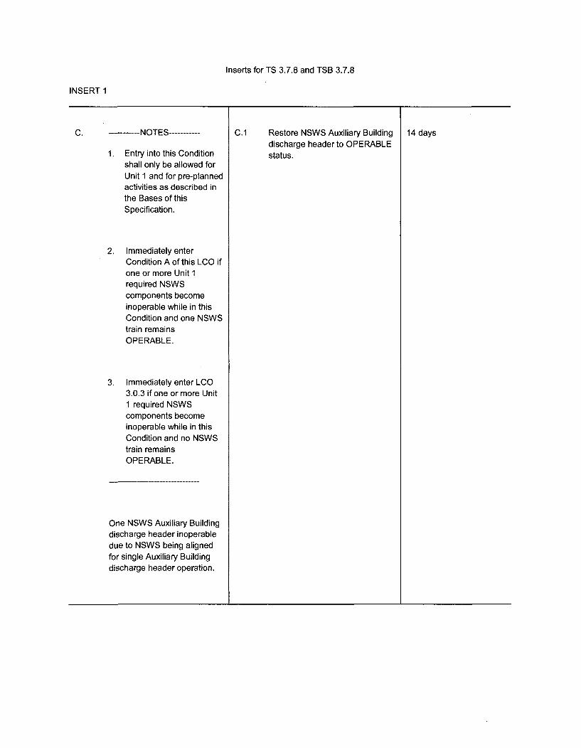
Inserts for TS 3.7.8 and TSB 3.7.8
INSERT 1
C. ----------- NOTES -----------
1. Entry into this Conditionshall only be allowed forUnit I and for pre-plannedactivities as described inthe Bases of thisSpecification.
2. Immediately enterCondition A of this LCO ifone or more Unit 1required NSWScomponents becomeinoperable while in thisCondition and one NSWStrain remainsOPERABLE.
3. Immediately enter LCO3.0.3 if one or more Unit1 required NSWScomponents becomeinoperable while in thisCondition and no NSWStrain remainsOPERABLE.
One NSWS Auxiliary Buildingdischarge header inoperabledue to NSWS being alignedfor single Auxiliary Buildingdischarge header operation.
C.1 Restore NSWS Auxiliary Buildingdischarge header to OPERABLEstatus.
14 days
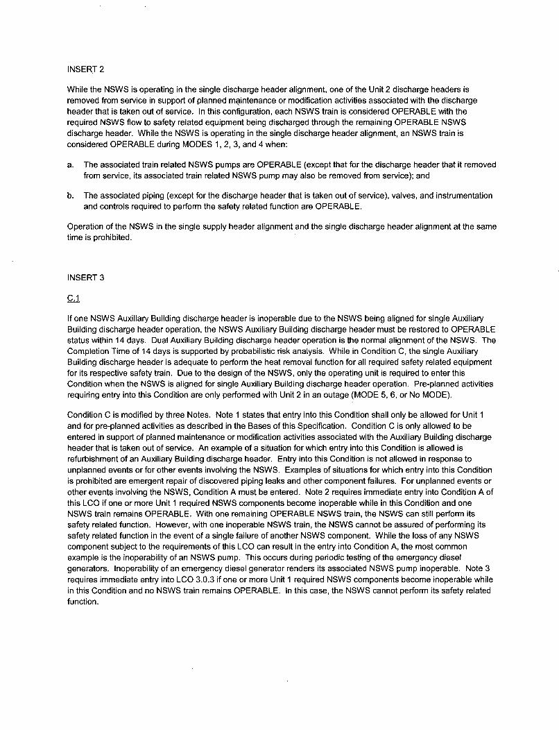
INSERT 2
While the NSWS is operating in the single discharge header alignment, one of the Unit 2 discharge headers isremoved from service in support of planned maintenance or modification activities associated with the dischargeheader that is taken out of service. In this configuration, each NSWS train is considered OPERABLE with therequired NSWS flow to safety related equipment being discharged through the remaining OPERABLE NSWSdischarge header. While the NSWS is operating in the single discharge header alignment, an NSWS train isconsidered OPERABLE during MODES 1, 2, 3, and 4 when:
a. The associated train related NSWS pumps are OPERABLE (except that for the discharge header that it removedfrom service, its associated train related NSWS pump may also be removed from service); and
b. The associated piping (except for the discharge header that is taken out of service), valves, and instrumentationand controls required to perform the safety related function are OPERABLE.
Operation of the NSWS in the single supply header alignment and the single discharge header alignment at the sametime is prohibited.
INSERT 3
C.1
If one NSWS Auxiliary Building discharge header is inoperable due to the NSWS being aligned for single AuxiliaryBuilding discharge header operation, the NSWS Auxiliary Building discharge header must be restored to OPERABLEstatus within 14 days. Dual Auxiliary Building discharge header operation is the normal alignment of the NSWS. TheCompletion Time of 14 days is supported by probabilistic risk analysis. While in Condition C, the single AuxiliaryBuilding discharge header is adequate to perform the heat removal function for all required safety related equipmentfor its respective safety train. Due to the design of the NSWS, only the operating unit is required to enter thisCondition when the NSWS is aligned for single Auxiliary Building discharge header operation. Pre-planned activitiesrequiring entry into this Condition are only performed with Unit 2 in an outage (MODE 5, 6, or No MODE).
Condition C is modified by three Notes. Note 1 states that entry into this Condition shall only be allowed for Unit 1and for pre-planned activities as described in the Bases of this Specification. Condition C is only allowed to beentered in support of planned maintenance or modification activities associated with the Auxiliary Building dischargeheader that is taken out of service. An example of a situation for which entry into this Condition is allowed isrefurbishment of an Auxiliary Building discharge header. Entry into this Condition is not allowed in response tounplanned events or for other events involving the NSWS. Examples of situations for which entry into this Conditionis prohibited are emergent repair of discovered piping leaks and other component failures. For unplanned events orother events involving the NSWS, Condition A must be entered. Note 2 requires immediate entry into Condition A ofthis LCO if one or more Unit 1 required NSWS components become inoperable while in this Condition and oneNSWS train remains OPERABLE. With one remaining OPERABLE NSWS train, the NSWS can still perform itssafety related function. However, with one inoperable NSWS train, the NSWS cannot be assured of performing itssafety related function in the event of a single failure of another NSWS component. While the loss of any NSWScomponent subject to the requirements of this LCO can result in the entry into Condition A, the most commonexample is the inoperability of an NSWS pump. This occurs during periodic testing of the emergency dieselgenerators. Inoperability of an emergency diesel generator renders its associated NSWS pump inoperable. Note 3requires immediate entry into LCO 3.0.3 if one or more Unit 1 required NSWS components become inoperable whilein this Condition and no NSWS train remains OPERABLE. In this case, the NSWS cannot perform its safety relatedfunction.

INSERT 4
or if the NSWS Auxiliary Building discharge header cannot be restored to OPERABLE status within the associatedCompletion Time,
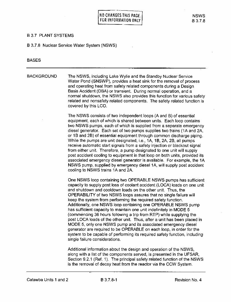
NO CHANGES THIS PAGE. NSWSFOR INFORMATION ONLY B 3.7.8
B 3.7 PLANT SYSTEMS
B 3.7.8 Nuclear Service Water System (NSWS)
BASES
BACKGROUND The NSWS, including Lake Wylie and the Standby Nuclear ServiceWater Pond (SNSWP), provides a heat sink for the removal of processand operating heat from safety related components during a DesignBasis Accident (DBA) or transient. During normal operation, and anormal shutdown, the NSWS also provides this function for various safetyrelated and nonsafety related components. The safety related function iscovered by this LCO.
The NSWS consists of two independent loops (A and B) of essentialequipment, each of which is shared between units. Each loop containstwo NSWS pumps, each of which is supplied from a separate emergencydiesel generator. Each set of two pumps supplies two trains (1A and 2A,or 1 B and 2B) of essential equipment through common discharge piping.While the pumps are unit designated, i.e., 1A, 1 B, 2A, 2B, all pumpsreceive automatic start signals from a safety injection or blackout signalfrom either unit. Therefore, a pump designated to one unit will supplypost accident cooling to equipment in that loop on both units, provided itsassociated emergency diesel generator is available. For example, the 1ANSWS pump, supplied by emergency diesel 1A, will supply post accidentcooling to NSWS trains 1A and 2A.
One NSWS loop containing two OPERABLE NSWS pumps has sufficientcapacity to supply post loss of coolant accident (LOCA) loads on one unitand shutdown and cooldown loads on the other unit. Thus, theOPERABILITY of two NSWS loops assures that no single failure willkeep the system from performing the required safety function.Additionally, one NSWS loop containing one OPERABLE NSWS pumphas sufficient capacity to maintain one unit indefinitely in MODE 5(commencing 36 hours following a trip from RTP) while supplying thepost LOCA loads of the other unit. Thus, after a unit has been placed inMODE 5, only one NSWS pump and its associated emergency dieselgenerator are required to be OPERABLE on each loop, in order for thesystem to be capable of performing its required safety function, includingsingle failure considerations.
Additional information about the design and operation of the NSWS,along with a list of the components served, is presented in the UFSAR,Section 9.2.1 (Ref. 1). The principal safety related function of the NSWSis the removal of decay heat from the reactor via the CCW System.
Catawba Units 1 and 2 B 3.7.8-1 Revision No. 4

NSWSB 3.7.8
BASES
APPLICABLESAFETY ANALYSES
The design basis of the NSWS is for one NSWS train, in conjunctionwith the CCW System and a containment spray system, to remove coredecay heat following a design basis LOCA as discussed in the UFSAR,Section 6.2 (Ref. 2). This prevents the containment sump fluid fromincreasing in temperature during the recirculation phase following aLOCA and provides for a gradual reduction in the temperature of this fluidas it is supplied to the Reactor Coolant System by the ECCS pumps.The NSWS is designed to perform its function with a single failure of anyactive component, assuming the loss of offsite power.
The NSWS, in conjunction with the CCW System, also cools the unitfrom residual heat removal (RHR), as discussed in the UFSAR,Section 5.4 (Ref. 3), from RHR entry conditions to MODE 5 during normaland post accident operations. The time required for this evolution is afunction of the number of CCW and RHR System trains that areoperating. Thirty six hours after a trip from RTP, one NSWS train issufficient to remove decay heat during subsequent operations inMODES 5 and 6. This assumes a maximum NSWS temperature, asimultaneous design basis event on the other unit, and the loss of offsitepower.
The NSWS satisfies Criterion 3 of 10 CFR 50.36 (Ref. 4).
LCO Two NSWS trains are required to be OPERABLE to provide the requiredredundancy to ensure that the system functions to remove post accidentheat loads, assuming that the worst case single active failure occurscoincident with the loss of offsite power. ,n A
While the NSWS is operating in the normal dual supply~eaderalignment, an NSWS train is considered OPERABLE during MODES 1, 2,3, and 4 when:
a. 1. Both NSWS pumps on the NSWS loop are OPERABLE; or
2. One unit's NSWS pump is OPERABLE and one unit'sflowpath to the non essential header, AFW pumps, andContainment Spray heat exchangers are isolated (orequivalent flow restrictions); and
b. The associated piping, valves, and instrumentation and controlsrequired to perform the safety related function are OPERABLE.
Catawba Units 1 and 2 B 3.7.8-2 Revision No.0

NSWSB 3.7.8
BASES
LCO (continued)
While the NSWS is operating in the single supply header alignment, oneof the supply headers is removed from service in support of plannedmaintenance or modification activities associated with the supply headerthat is taken out of service. In this configuration, each NSWS train isconsidered OPERABLE with the required NSWS flow to safety relatedequipment being fed through the remaining OPERABLE NSWS supplyheader. While the NSWS is operating in the single supply headeralignment, an NSWS train is considered OPERABLE during MODES 1, 2,3, and 4 when:
a. The associated train related NSWS pumps are OPERABLE; and
b. The associated piping (except for the supply header that is takenout of service), valves, and instrumentation and controls required toperform the safety related function are OPERABLE.
Te NSWS system is shared between the two units. The shared portionsof the system must be OPERABLE for each unit when that unit is in theMODE of Applicability. Additionally, both normal and emergency powerfor shared components must also be OPERABLE. If a shared NSWScomponent becomes inoperable, or normal or emergency power toshared components becomes inoperable, then the Required Actions ofthis LCO must be entered independently for each unit that is in theMODE of applicability of the LCO, except as noted in a.2 above foroperation in the normal dual supply header alignment. In this case,sufficient flow is available, however, this configuration results ininoperabilities within other required systems on one unit and theassociated Required Actions must be entered. Use of a NSWS pumpand associated diesel generator on a shutdown unit to support continuedoperation (> 72 hours) of a unit with an inoperable NSWS pump isprohibited. A shutdown unit supplying its associated emergency powersource (1 EMXG/2EMXH) cannot be credited for OPERABILITY ofcomponents supporting the operating unit.
APPLICABILITY In MODES 1, 2, 3, and 4, the NSWS is a normally operating system thatis required to support the OPERABILITY of the equipment serviced bythe NSWS and required to be OPERABLE in these MODES.
In MODES 5 and 6, the requirements of the NSWS are determined by thesystems it supports.
Catawba Units 1 and 2 B 3.7.8-3 Revision NoAnW

NO CHANGES THIS PAGE. NSWS
FOR INFORMATION ONLY B 3.7.8
BASES
ACTIONS A. 1
If one NSWS train is inoperable, action must be taken to restoreOPERABLE status within 72 hours. In this Condition, the remainingOPERABLE NSWS train is adequate to perform the heat removalfunction. However, the overall reliability is reduced because a singlefailure in the OPERABLE NSWS train could result in loss of NSWSfunction. Due to the shared nature of the NSWS, both units are requiredto enter a 72 hour Action when a NSWS Train becomes inoperable oneither unit. Required Action A.1 is modified by two Notes. The first Noteindicates that the applicable Conditions and Required Actions ofLCO 3.8.1, "AC Sources-Operating," should be entered if an inoperableNSWS train results in an inoperable emergency diesel generator. Thesecond Note indicates that the applicable Conditions and RequiredActions of LCO 3.4.6, "RCS Loops-MODE 4," should be entered if aninoperable NSWS train results in an inoperable decay heat removal train(RHR). An example of when these Notes should be applied is with bothunits' loop 'A' NSWS pumps inoperable, both units' 'A' emergency dieselgenerators and both units' 'A' RHR systems should be declaredinoperable and appropriate Actions entered. This is an exception toLCO 3.0.6 and ensures the proper actions are taken for thesecomponents. The 72 hour Completion Time is based on the redundantcapabilities afforded by the OPERABLE train, and the low probability of aDBA occurring during this time period.
B.1
If one NSWS supply header is inoperable due to the NSWS being alignedfor single supply header operation, the NSWS supply header must berestored to OPERABLE status within 30 days. Dual supply headeroperation is the normal alignment of the NSWS. The Completion Time of30 days is supported by probabilistic risk analysis. While in Condition B,the single supply header is adequate to perform the heat removalfunction for all required safety related equipment for both safety trains.Due to the shared nature of the NSWS, both units are required to enterthis Condition when the NSWS is aligned for single supply headeroperation. In order to prevent the potential for NSWS pump runout, thesingle NSWS pump flow balance alignment is prohibited while the NSWSis aligned for single supply header operation.
Catawba Units 1 and 2 B 3.7.8-4 Revision No. 4
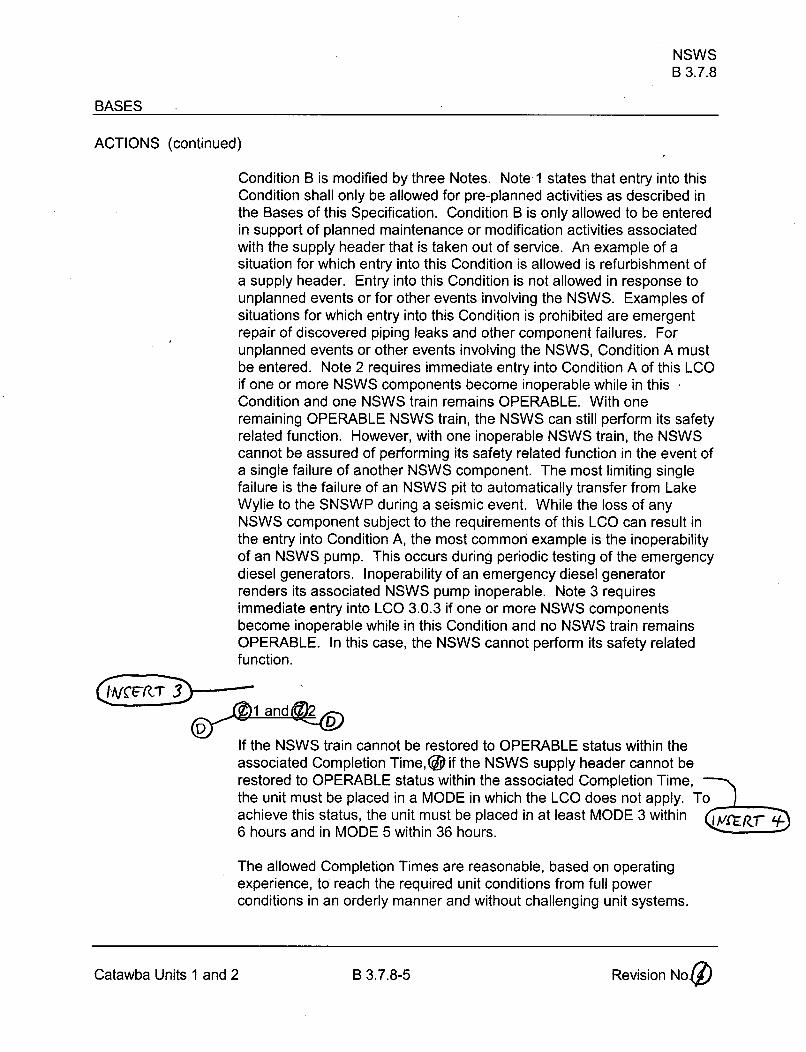
NSWSB 3.7.8
BASES
ACTIONS (continued)
Condition B is modified by three Notes. Note 1 states that entry into thisCondition shall only be allowed for pre-planned activities as described inthe Bases of this Specification. Condition B is only allowed to be enteredin support of planned maintenance or modification activities associatedwith the supply header that is taken out of service. An example of asituation for which entry into this Condition is allowed is refurbishment ofa supply header. Entry into this Condition is not allowed in response tounplanned events or for other events involving the NSWS. Examples ofsituations for which entry into this Condition is prohibited are emergentrepair of discovered piping leaks and other component failures. Forunplanned events or other events involving the NSWS, Condition A mustbe entered. Note 2 requires immediate entry into Condition A of this LCOif one or more NSWS components become inoperable while in thisCondition and one NSWS train remains OPERABLE. With oneremaining OPERABLE NSWS train, the NSWS can still perform its safetyrelated function. However, with one inoperable NSWS train, the NSWScannot be assured of performing its safety related function in the event ofa single failure of another NSWS component. The most limiting singlefailure is the failure of an NSWS pit to automatically transfer from LakeWylie to the SNSWP during a seismic event. While the loss of anyNSWS component subject to the requirements of this LCO can result inthe entry into Condition A, the most common example is the inoperabilityof an NSWS pump. This occurs during periodic testing of the emergencydiesel generators. Inoperability of an emergency diesel generatorrenders its associated NSWS pump inoperable. Note 3 requiresimmediate entry into LCO 3.0.3 if one or more NSWS componentsbecome inoperable while in this Condition and no NSWS train remainsOPERABLE. In this case, the NSWS cannot perform its safety relatedfunction.
If the NSWS train cannot be restored to OPERABLE status within theassociated Completion Time, (D if the NSWS supply header cannot berestored to OPERABLE status within the associated Completion Time,the unit must be placed in a MODE in which the LCO does not apply. To .achieve this status, the unit must be placed in at least MODE 3 within CE/Z 16 hours and in MODE 5 within 36 hours.
The allowed Completion Times are reasonable, based on operatingexperience, to reach the required unit conditions from full powerconditions in an orderly manner and without challenging unit systems.
Catawba Units 1 and 2 B 3.7.8-5 Revision Noj•
NSWSB 3.7.8
BASES
SURVEILLANCE SR 3.7.8.1REQUIREMENTS
This SR is modified by a Note indicating that the isolation of the NSWScomponents or systems may render those components inoperable, butdoes not affect the OPERABILITY of the NSWS.
Verifying the correct alignment for manual, power operated, andautomatic valves in the NSWS flow path provides assurance that theproper flow paths exist for NSWS operation. This SR does not apply tovalves that are locked, sealed, or otherwise secured in position, sincethey are verified to be in the correct position prior to being locked, sealed,or secured. This SR does not require any testing or valve manipulation;rather, it involves verification that those valves capable of beingmispositioned are in the correct position. This SR does not apply tovalves that cannot be inadvertently misaligned, such as check valves.The Surveillance Frequency is based on operating experience,equipment reliability, and plant risk and is controlled under theSurveillance Frequency Control Program.
SR 3.7.8.2
This SR verifies proper automatic operation of the NSWS valves on anactual or simulated actuation signal. The signals that cause the actuationare from Safety Injection and Phase 'B' isolation. The NSWS is anormally operating system that cannot be fully actuated as part of normaltesting. This Surveillance is not required for valves that are locked,sealed, or otherwise secured in the required position under administrativecontrols. The Surveillance Frequency is based on operating experience,equipment reliability, and plant risk and is controlled under theSurveillance Frequency Control Program.
This SR is modified by a Note that states that the SR is not required to bemet for valves that are maintained in position to support NSWS singlesupply)header operation. When the NSWS is placed in this alignment,certain automatic valves in the system are maintained in position and willnot automatically reposition in response to an actuation signal while theNSWS is in this alignment.
Catawba Units 1 and 2 B 3.7.8-6 Revision No.(71\Z/
NO CHANGES THIS PAGE. NSWS
FOR INFORMATION ONLY B 3.7.8
BASES
SURVEILLANCE REQUIREMENTS (continued)
SR 3.7.8.3
This SR verifies proper automatic operation of the NSWS pumps on anactual or simulated actuation signal. The signals that cause the actuationare from Safety Injection and Loss of Offsite Power. The NSWS is anormally operating system that cannot be fully actuated as part of normaltesting during normal operation. The Surveillance Frequency is based onoperating experience, equipment reliability, and plant risk and iscontrolled under the Surveillance Frequency Control Program.
REFERENCES 1. UFSAR, Section 9.2.
2. UFSAR, Section 6.2.
3. UFSAR, Section 5.4.
4. 10 CFR 50.36, Technical Specifications, (c)(2)(ii).
Catawba Units 1 and 2 B 3.7-8-7 Revision No. 4

ATTACHMENT 4
LIST OF NRC COMMITMENTS

The following NRC commitments are being made in support of this amendment requestsubmittal:
1. The approved amendments will be implemented within 60 days from the date ofNRC approval. "Implemented" means that the approved amendments will havebeen placed into the control room copies of the TS. However, the provisionsafforded by the approved amendments may not actually be utilized until suchtime in the future that Duke Energy determines to be appropriate.
2. Prior to actually utilizing the provisions afforded by the approved amendments,Catawba will have in place all required document and process changesnecessary to support these provisions. In addition, all required design changeswill have been fully implemented.
Attachment 4 Page 1