novell extend composer uts connect filemust retain the above copyright notices, this list of...
TRANSCRIPT

Novell exteNd Composer™
UTS Connect
USER’S GUIDE
www.novell.com5.0

Legal NoticesCopyright © 2000, 2001, 2002, 2003, 2004 SilverStream Software, LLC. All rights reserved.
Title to the Software and its documentation, and patents, copyrights and all other property rights applicable thereto, shall at all times remain solely and exclusively with SilverStream and its licensors, and you shall not take any action inconsistent with such title. The Software is protected by copyright laws and international treaty provisions. You shall not remove any copyright notices or other proprietary notices from the Software or its documentation, and you must reproduce such notices on all copies or extracts of the Software or its documentation. You do not acquire any rights of ownership in the Software.
Novell, Inc.
1800 South Novell Place
Provo, UT 85606
www.novell.com
exteNd Composer UTS Connect User’s Guide
January 2004

Online Documentation: To access the online documentation for this and other Novell products, and to get updates, see www.novell.com/documentation.
Novell TrademarkseDirectory is a trademark of Novell, Inc.exteNd is a trademark of Novell, Inc.exteNd Composer is a trademark of Novell, Inc.exteNd Director is a trademark of Novell, Inc.jBroker is a trademark of Novell, Inc.NetWare is a registered trademark of Novell, Inc.Novell is a registered trademark of Novell, Inc.
SilverStream TrademarksSilverStream is a registered trademark of SilverStream Software, LLC.
Third-Party TrademarksAll third-party trademarks are the property of their respective owners.
Third-Party Software Legal NoticesJakarta-Regexp Copyright ©1999 The Apache Software Foundation. All rights reserved. Xalan Copyright ©1999 The Apache Software Foundation. All rights reserved. Xerces Copyright ©1999-2000 The Apache Software Foundation. All rights reserved. Jakarta-Regexp , Xalan and Xerces software is licensed by The Apache Software Foundation and redistribution and use of Jakarta-Regexp, Xalan and Xerces in source and binary forms, with or without modification, are permitted provided that the following conditions are met: 1. Redistributions of source code must retain the above copyright notices, this list of conditions and the following disclaimer. 2. Redistributions in binary form must reproduce the above copyright notice, this list of conditions and the following disclaimer in the documentation and/or other materials provided with the distribution. 3. The end-user documentation included with the redistribution, if any, must include the following acknowledgment: "This product includes software developed by the Apache Software Foundation (http://www.apache.org/)." Alternately, this acknowledgment may appear in the software itself, if and wherever such third-party acknowledgments normally appear. 4. The names "The Jakarta Project", "Jakarta-Regexp", "Xerces", "Xalan" and "Apache Software Foundation" must not be used to endorse or promote products derived from this software without prior written permission. For written permission, please contact [email protected]. 5. Products derived from this software may not be called "Apache" nor may "Apache" appear in their name, without prior written permission of The Apache Software Foundation. THIS SOFTWARE IS PROVIDED "AS IS" AND ANY EXPRESSED OR IMPLIED WARRANTIES, INCLUDING, BUT NOT LIMITED TO, THE IMPLIED WARRANTIES OF MERCHANTABILITY AND FITNESS FOR A PARTICULAR PURPOSE ARE DISCLAIMED. IN NO EVENT SHALL THE APACHE SOFTWARE FOUNDATION OR ITS CONTRIBUTORS BE LIABLE FOR ANY DIRECT, INDIRECT, INCIDENTAL, SPECIAL, EXEMPLARY, OR CONSEQUENTIAL DAMAGES (INCLUDING, BUT NOT LIMITED TO, PROCUREMENT OF SUBSTITUTE GOODS OR SERVICES; LOSS OF USE, DATA, OR PROFITS; OR BUSINESS INTERRUPTION) HOWEVER CAUSED AND ON ANY THEORY OF LIABILITY, WHETHER IN CONTRACT, STRICT LIABILITY, OR TORT (INCLUDING NEGLIGENCE OR OTHERWISE) ARISING IN ANY WAY OUT OF THE USE OF THIS SOFTWARE, EVEN IF ADVISED OF THE POSSIBILITY OF SUCH DAMAGE.
Copyright ©1996-2000 Autonomy, Inc.
Copyright ©2000 Brett McLaughlin & Jason Hunter. All rights reserved. Redistribution and use in source and binary forms, with or without modification, are permitted provided that the following conditions are met: 1. Redistributions of source code must retain the above copyright notice, this list of conditions, and the following disclaimer. 2. Redistributions in binary form must reproduce the above copyright notice, this list of conditions, and the disclaimer that follows these conditions in the documentation and/or other materials provided with the distribution. 3. The name "JDOM" must not be used to endorse or promote products derived from this software without prior written permission. For written permission, please contact [email protected]. 4. Products derived from this software may
not be called "JDOM", nor may "JDOM" appear in their name, without prior written permission from the JDOM Project Management ([email protected]). THIS SOFTWARE IS PROVIDED "AS IS" AND ANY EXPRESSED OR IMPLIED WARRANTIES, INCLUDING, BUT NOT LIMITED TO, THE IMPLIED WARRANTIES OF MERCHANTABILITY AND FITNESS FOR A PARTICULAR PURPOSE ARE DISCLAIMED. IN NO EVENT SHALL THE APACHE SOFTWARE FOUNDATION OR ITS CONTRIBUTORS BE LIABLE FOR ANY DIRECT, INDIRECT, INCIDENTAL, SPECIAL, EXEMPLARY, OR CONSEQUENTIAL DAMAGES (INCLUDING, BUT NOT LIMITED TO, PROCUREMENT OF SUBSTITUTE GOODS OR SERVICES; LOSS OF USE, DATA, OR PROFITS; OR BUSINESS INTERRUPTION) HOWEVER CAUSED AND ON ANY THEORY OF LIABILITY, WHETHER IN CONTRACT, STRICT LIABILITY, OR TORT (INCLUDING NEGLIGENCE OR OTHERWISE) ARISING IN ANY WAY OUT OF THE USE OF THIS SOFTWARE, EVEN IF ADVISED OF THE POSSIBILITY OF SUCH DAMAGE.
This Software is derived in part from the SSLava™ Toolkit, which is Copyright ©1996-1998 by Phaos Technology Corporation. All Rights Reserved. Customer is prohibited from accessing the functionality of the Phaos software.
The code of this project is released under a BSD-like license [license.txt]: Copyright 2000-2002 (C) Intalio Inc. All Rights Reserved. Redistribution and use of this software and associated documentation ("Software"), with or without modification, are permitted provided that the following conditions are met: 1. Redistributions of source code must retain copyright statements and notices. Redistributions must also contain a copy of this document. 2. Redistributions in binary form must reproduce the above copyright notice, this list of conditions, and the following disclaimer in the documentation and/or other materials provided with the distribution. 3. The name "ExoLab" must not be used to endorse or promote products derived from this Software without prior written permission of Intalio Inc. For written permission, please contact [email protected]. 4. Products derived from this Software may not be called "Castor" nor may "Castor" appear in their names without prior written permission of Intalio Inc. Exolab, Castor, and Intalio are trademarks of Intalio Inc. 5. Due credit should be given to the ExoLab Project (http://www.exolab.org/). THIS SOFTWARE IS PROVIDED BY INTALIO AND CONTRIBUTORS ``AS IS'' AND ANY EXPRESSED OR IMPLIED WARRANTIES, INCLUDING, BUT NOT LIMITED TO, THE IMPLIED WARRANTIES OF MERCHANTABILITY AND FITNESS FOR A PARTICULAR PURPOSE, ARE DISCLAIMED. IN NO EVENT SHALL INTALIO OR ITS CONTRIBUTORS BE LIABLE FOR ANY DIRECT, INDIRECT, INCIDENTAL, SPECIAL, EXEMPLARY, OR CONSEQUENTIAL DAMAGES (INCLUDING, BUT NOT LIMITED TO, PROCUREMENT OF SUBSTITUTE GOODS OR SERVICES; LOSS OF USE, DATA, OR PROFITS; OR BUSINESS INTERRUPTION) HOWEVER CAUSED AND ON ANY THEORY OF LIABILITY, WHETHER IN CONTRACT, STRICT LIABILITY, OR TORT (INCLUDING NEGLIGENCE OR OTHERWISE) ARISING IN ANY WAY OUT OF THE USE OF THIS SOFTWARE, EVEN IF ADVISED OF THE POSSIBILITY OF SUCH DAMAGE.

iiiiiiiiiiii
Contents
About This Guide vii
1111 Welcome to exteNd Composer and UTS Connect 15Before You Begin . . . . . . . . . . . . . . . . . . . . . . . . . . . . . . . . . . . . . . . .15About exteNd Composer Connects . . . . . . . . . . . . . . . . . . . . . . . . . . . . . . .15What is the UTS Connect?. . . . . . . . . . . . . . . . . . . . . . . . . . . . . . . . . . . .17About exteNd Composer's UTS Component. . . . . . . . . . . . . . . . . . . . . . . . . . .17What Applications Can You Build Using the UTS Connect?. . . . . . . . . . . . . . . . . . .18
2222 Getting Started with the UTS Component Editor 19Steps Commonly Used to Create a UTS Component . . . . . . . . . . . . . . . . . . . . . .19
Creating XML Templates for Your Component . . . . . . . . . . . . . . . . . . . . . . .19Creating a UTS Connection Resource . . . . . . . . . . . . . . . . . . . . . . . . . . .20Connection Resources . . . . . . . . . . . . . . . . . . . . . . . . . . . . . . . . . . .20Constant and Expression Driven Connections . . . . . . . . . . . . . . . . . . . . . . .22
3333 Creating a UTS Component 25Creating a UTS Component . . . . . . . . . . . . . . . . . . . . . . . . . . . . . . . . . . .25About the UTS Component Editor Window . . . . . . . . . . . . . . . . . . . . . . . . . . .28About the UTS Native Environment Pane . . . . . . . . . . . . . . . . . . . . . . . . . . . .29UTS Keyboard Support . . . . . . . . . . . . . . . . . . . . . . . . . . . . . . . . . . . . .29About the Screen Object . . . . . . . . . . . . . . . . . . . . . . . . . . . . . . . . . . . . .31
What it is . . . . . . . . . . . . . . . . . . . . . . . . . . . . . . . . . . . . . . . . . .31How it works . . . . . . . . . . . . . . . . . . . . . . . . . . . . . . . . . . . . . . . .31
UTS-Specific Toolbar Buttons . . . . . . . . . . . . . . . . . . . . . . . . . . . . . . . . . .32UTS-Specific Menu Bar Items . . . . . . . . . . . . . . . . . . . . . . . . . . . . . . . . . .34UTS-Specific Context-Menu Items . . . . . . . . . . . . . . . . . . . . . . . . . . . . . . . .34
Native Environment Pane Context Menu . . . . . . . . . . . . . . . . . . . . . . . . . .35Action Pane Context Menu . . . . . . . . . . . . . . . . . . . . . . . . . . . . . . . . .35
4444 Performing Basic UTS Actions 37About Actions . . . . . . . . . . . . . . . . . . . . . . . . . . . . . . . . . . . . . . . . . .37About UTS-Specific Actions . . . . . . . . . . . . . . . . . . . . . . . . . . . . . . . . . . .37
The Set Screen Text Action. . . . . . . . . . . . . . . . . . . . . . . . . . . . . . . . .38The Send Key Action . . . . . . . . . . . . . . . . . . . . . . . . . . . . . . . . . . . .40The Check Screen Action . . . . . . . . . . . . . . . . . . . . . . . . . . . . . . . . . .41Using Actions in Record Mode . . . . . . . . . . . . . . . . . . . . . . . . . . . . . . .43
UTS-Specific Expression Builder Extensions . . . . . . . . . . . . . . . . . . . . . . . . . .43Login . . . . . . . . . . . . . . . . . . . . . . . . . . . . . . . . . . . . . . . . . . . .44Screen Methods . . . . . . . . . . . . . . . . . . . . . . . . . . . . . . . . . . . . . .44
Multi-row Screen Selections in the UTS Connect . . . . . . . . . . . . . . . . . . . . . . . .50
Novell UTS Connect User’s Guideiviviviv
Selecting Continuous Data. . . . . . . . . . . . . . . . . . . . . . . . . . . . . . . . . 50Selecting Rectangular Regions . . . . . . . . . . . . . . . . . . . . . . . . . . . . . . 51
5555 UTS Components in Action 53The Sample Transaction . . . . . . . . . . . . . . . . . . . . . . . . . . . . . . . . . . . . 53Recording a UTS Session. . . . . . . . . . . . . . . . . . . . . . . . . . . . . . . . . . . . 53Editing a Previously Recorded Action Model . . . . . . . . . . . . . . . . . . . . . . . . . . 61
Editing or Adding to an Existing Action . . . . . . . . . . . . . . . . . . . . . . . . . . 61Deleting an Action . . . . . . . . . . . . . . . . . . . . . . . . . . . . . . . . . . . . . 65Looping Over Multiple Rows in Search of Data . . . . . . . . . . . . . . . . . . . . . . 65
Testing your UTS Component . . . . . . . . . . . . . . . . . . . . . . . . . . . . . . . . . 66Using the Animation Tools . . . . . . . . . . . . . . . . . . . . . . . . . . . . . . . . . . . 68Data Sets that Span Screens . . . . . . . . . . . . . . . . . . . . . . . . . . . . . . . . . . 69
Multiple Screens . . . . . . . . . . . . . . . . . . . . . . . . . . . . . . . . . . . . . . 70Dealing with Redundant Data . . . . . . . . . . . . . . . . . . . . . . . . . . . . . . . . . . 70Tips for Building Reliable UTS Components . . . . . . . . . . . . . . . . . . . . . . . . . . 72Using Other Actions in the UTS Component Editor . . . . . . . . . . . . . . . . . . . . . . . 73Handling Errors and Messages . . . . . . . . . . . . . . . . . . . . . . . . . . . . . . . . . 73Finding a “Bad” Action . . . . . . . . . . . . . . . . . . . . . . . . . . . . . . . . . . . . . 74Performance Considerations . . . . . . . . . . . . . . . . . . . . . . . . . . . . . . . . . . 75
6666 Logon Components, Connections, and Connection Pools 77About UTS Terminal Session Performance. . . . . . . . . . . . . . . . . . . . . . . . . . . 77
When Will I Need Logon Components? . . . . . . . . . . . . . . . . . . . . . . . . . . 77Connection Pool Architecture . . . . . . . . . . . . . . . . . . . . . . . . . . . . . . . . . . 78
The Logon Connection’s Role in Pooling . . . . . . . . . . . . . . . . . . . . . . . . . 81How Many Pools Do I Need? . . . . . . . . . . . . . . . . . . . . . . . . . . . . . . . 82Pieces Required for Pooling . . . . . . . . . . . . . . . . . . . . . . . . . . . . . . . . 82
How Do I Implement Pooling? . . . . . . . . . . . . . . . . . . . . . . . . . . . . . . . . . 83The UTS Logon Component . . . . . . . . . . . . . . . . . . . . . . . . . . . . . . . . . . 83
Logon, Keep Alive, and Logoff Actions . . . . . . . . . . . . . . . . . . . . . . . . . . 84LOGON Actions . . . . . . . . . . . . . . . . . . . . . . . . . . . . . . . . . . . . . . 85Keep Alive Actions . . . . . . . . . . . . . . . . . . . . . . . . . . . . . . . . . . . . . 86Logoff Actions . . . . . . . . . . . . . . . . . . . . . . . . . . . . . . . . . . . . . . . 88Logon Component Life Cycle . . . . . . . . . . . . . . . . . . . . . . . . . . . . . . . 89
About the UTS Logon Connection . . . . . . . . . . . . . . . . . . . . . . . . . . . . . . . 90Connection Pooling with a Single Sign-On. . . . . . . . . . . . . . . . . . . . . . . . . 91
Creating a Connection Pool. . . . . . . . . . . . . . . . . . . . . . . . . . . . . . . . . . . 92Overview . . . . . . . . . . . . . . . . . . . . . . . . . . . . . . . . . . . . . . . . . . 92
Creating a Basic UTS Connection . . . . . . . . . . . . . . . . . . . . . . . . . . . . . . . 92Creating a Logon Component. . . . . . . . . . . . . . . . . . . . . . . . . . . . . . . . . . 93Creating a Logon Connection using a Pool Connection . . . . . . . . . . . . . . . . . . . . 95Creating a Logon Connection using a Session Connection. . . . . . . . . . . . . . . . . . 101Creating a UTS Component That Uses Pooled Connections. . . . . . . . . . . . . . . . . 103

vvvv
Managing Pools . . . . . . . . . . . . . . . . . . . . . . . . . . . . . . . . . . . . . . . . 104Using the exteNd Composer Console . . . . . . . . . . . . . . . . . . . . . . . . . . 104
Connection Pool Management and Deployed Services . . . . . . . . . . . . . . . . . . . . 108Connection Discard Behavior . . . . . . . . . . . . . . . . . . . . . . . . . . . . . . . 109Screen Synchronization. . . . . . . . . . . . . . . . . . . . . . . . . . . . . . . . . . 109
AAAA Glossary 111
BBBB UTS Display Attributes 113
CCCC Reserved Words 117
Novell UTS Connect User’s Guidevivivivi
vii
About This Guide
Purpose
The guide describes how to use exteNd Composer UTS Connect, referred to as the UTS Component Editor. The UTS Component Editor is a separately-installed component editor in exteNd Composer.
Audience
The audience for the guide is developers and system integrators using exteNd Composer to create Web services and components which integrate UTS applications.
Prerequisites
The guide assumes the reader is familiar with and has used exteNd Composer’s development environment and deployment tools. You must also have an understanding of the UTS environment and building or using applications utilizing UTS. Familiarity with other mainframe terminal emulators, such as UTS, 3270, 5250 or VT-series terminals (e.g. VT100) would also be helpful as you read through this guide.
Additional documentation
For the complete set of Novell exteNd Composer documentation, see the Novell Documentation Web Site (http://www.novell.com/documentation-index/index.jsp).
Organization
The guide is organized as follows:

viii UTS Connect User’s Guide
Chapter 1, Welcome to exteNd Composer and UTS User Interface, gives a definition and overview of the UTS Connect and Component Editor and the types of applications you may build using them.
Chapter 2, Getting Started with the UTS Component Editor, describes the necessary preparations for creating a UTS component.
Chapter 3, Creating a UTS Component, describes the different parts of the component editor.
Chapter 4, Performing UTS Actions, describes how to use the basic UTS actions, as well as the unique features of the UTS Connect.
Chapter 5, UTS Components in Action, demonstrates using UTS components and actions using a sample application in the context of an Action Model.
Chapter 6, Logon Components, Connections, and Connection Pools, describes how to enhance performance through use of shared connections.
Appendix A, is a glossary.
Appendix B, UTS Attributes, and their display significance along with a discussion of how to use the getattribute( ).
Appendix C, Reserved Words, lists those words used only for UTS Connect.
Conventions Used in the Guide
The guide uses the following typographical conventions.
Bold typeface within instructions indicate action items, including:
Menu selections
Form selections
Dialog box items
Sans-serif bold typeface is used for:
Uniform Resource Identifiers
File names
Directories and partial pathnames
Italic typeface indicates:
Variable information that you supply
Technical terms used for the first time
Title of other Novell publications
Monospaced typeface indicates:

ix
Method names
Code examples
System input
Operating system objects

x UTS Connect User’s Guide

15
1
Welcome to exteNd Composer and UTS Connect
Welcome to exteNd Composer and UTS Connect Chapter 1
Before You BeginWelcome to the UTS Connect Guide. This Guide is a companion to the exteNd Composer User's Guide, which details how to use all the features of exteNd Composer, except for the Connect Component Editors. If you haven't looked at the Composer User's Guide yet, please familiarize yourself with it before using this Guide.
exteNd Composer provides separate Component Editors for each Connect. The special features of each component editor are described in separate Guides like this one.
If you have been using exteNd Composer, and are familiar with the XML Map Component Editor, then this Guide should get you started with the UTS Component Editor.
Before you can begin working with the UTS Connect you must have installed it into your existing exteNd Composer. Likewise, before you can run any Services built with this Connect in the exteNd Composer Enterprise Server environment, you must have already installed the server-side software for this Connect into Composer Enterprise Server.
NOTE: To be successful with this Component Editor, you must be familiar with the UTS environment and the particular applications that you want to XML-enable.
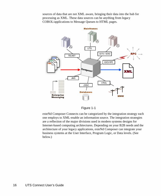
About exteNd Composer ConnectsexteNd Composer is built upon a simple hub and spoke architecture (Fig.1-1). The hub is a robust XML transformation engine that accepts requests via XML documents, performs transformation processes on those documents and interfaces with XML-enabled applications, and returns an XML response document. The spokes, or Connects, are plug-in modules that "XML-enable"
UTS Connect User’s Guide16
sources of data that are not XML aware, bringing their data into the hub for processing as XML. These data sources can be anything from legacy COBOL/applications to Message Queues to HTML pages.
Figure 1-1
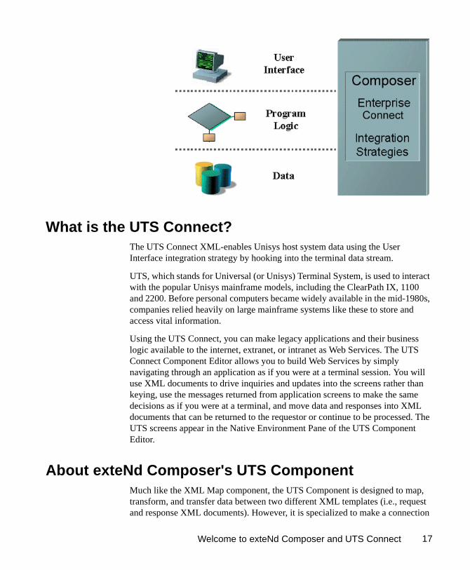
exteNd Composer Connects can be categorized by the integration strategy each one employs to XML-enable an information source. The integration strategies are a reflection of the major divisions used in modern systems designs for Internet-based computing architectures. Depending on your B2B needs and the architecture of your legacy applications, exteNd Composer can integrate your business systems at the User Interface, Program Logic, or Data levels. (See below.)
Welcome to exteNd Composer and UTS Connect 17
What is the UTS Connect?The UTS Connect XML-enables Unisys host system data using the User Interface integration strategy by hooking into the terminal data stream.
UTS, which stands for Universal (or Unisys) Terminal System, is used to interact with the popular Unisys mainframe models, including the ClearPath IX, 1100 and 2200. Before personal computers became widely available in the mid-1980s, companies relied heavily on large mainframe systems like these to store and access vital information.
Using the UTS Connect, you can make legacy applications and their business logic available to the internet, extranet, or intranet as Web Services. The UTS Connect Component Editor allows you to build Web Services by simply navigating through an application as if you were at a terminal session. You will use XML documents to drive inquiries and updates into the screens rather than keying, use the messages returned from application screens to make the same decisions as if you were at a terminal, and move data and responses into XML documents that can be returned to the requestor or continue to be processed. The UTS screens appear in the Native Environment Pane of the UTS Component Editor.
About exteNd Composer's UTS ComponentMuch like the XML Map component, the UTS Component is designed to map, transform, and transfer data between two different XML templates (i.e., request and response XML documents). However, it is specialized to make a connection
UTS Connect User’s Guide18
to a Unisys UTS host application, process the data using elements from a screen, and then map the results to an output DOM. You can then act upon the output DOM in any way that makes sense for your integration application. In essence, you're able to capture data from, or push data to, a host system without ever having to alter the host system itself.
A UTS Component can perform simple data manipulations, such as mapping and transferring data from an XML document into a host program, or perform "screen scraping" of a UTS transaction, putting the harvested data into an XML document. A UTS Component has all the functionality of the XML Map Component and can process XSL, send mail, and post and receive XML documents using the HTTP protocol.
What Applications Can You Build Using the UTS Connect?
exteNd Composer, and consequently the UTS Connect, can be applied to the the following types of applications:
1 Business to Business Web Service interactions such as supply chain applications.
2 Consumer to Business interactions such as self-service applications from Web Browsers.
3 Enterprise Application Integrations where information from heterogeneous systems is combined or chained together.
Fundamentally, the UTS Component Editor allows you to extend any XML integration you are building to include any of your business applications that support UTS-based terminal interactions (See the exteNd Composer User's Guide for more information.)
For example, you may have an application that retrieves a product's description, picture, price, and inventory from regularly updated databases and displays it in a Web browser. By using the UTS Component Editor, you can now get the current product information from the operational systems and the static information (e.g., a picture) from a database and merge the information from these separate information sources before displaying it to a user. This provides the same current information to both your internal and external users.

19
2
Getting Started with the UTS Component Editor
Getting Started with the UTS Component Editor Chapter 2
Steps Commonly Used to Create a UTS ComponentWhile there are many ways to go about creating UTS Components, the most commonly used steps in creating a simple component are as follows:
Create XML Template(s) for the program.
Create a UTS Connection Resource.
Create a UTS Component.
Enter Record mode and navigate through the program using terminal emulation available via the component editor’s Native Environment Pane.
Drag and drop input-document data into the screen as needed.
Drag and drop screen results into the output document.
Stop recording.
This chapter will cover the first two steps in this process.
Creating XML Templates for Your Component
Although it is not strictly necessary to do so, your UTS Component may require you to create XML templates so that you have sample documents for designing your component. (For more information, see Chapter 5, “Creating XML Templates,” in the exteNd Composer User's Guide.)
In many cases, your input documents will be designed to contain data that a terminal operator might type into the program interactively. Likewise, the output documents are designed to receive data returned to the screen as a result of the operator's input. For example, in a typical business scenario, a terminal operator may receive a phone request from a customer interested in the price or availability of an item. The operator would typically query the host system via his or her UTS terminal session by entering information (such as a part number) into a terminal when prompted. A short time later, the host responds by returning

UTS Connect User’s Guide20
data to the terminal screen, and the operator relays this information to the customer. This session could be carried out by an exteNd Composer Web Service that uses a UTS Component. The requested part number might be represented as a data element in an XML input document. The looked-up data returned from the host would appear in the component’s output document. That data might in turn be output to a web page, or sent to another business process as XML, etc.
NOTE: Your component design may call for other xObject resources, such as custom scripts or Code Table maps. If so, it is also best to create these objects before creating the UTS Component. For more information, see the exteNd Composer User's Guide.
Creating a UTS Connection Resource
Once you have the XML templates in place, your next step will be to create a Connection Resource to access the host program. If you try to create a UTS Component in the absence of any available Connection Resources, a dialog will appear, asking if you wish to create a Connection Resource. By answering Yes to this dialog, you will be taken to the appropriate wizard.
Connection Resources
When you create a Connection Resource for the UTS Component, you will have what appear to be three choices: a straight Connection, a Logon Connection and a MultiBridge Connection. Generally speaking, you will use the straight UTS Connection to connect to your host environment. The Logon Connection is used for connection pooling, which will be explained in greater detail in Chapter 6 of this Guide. The MultiBridge Connection is a gateway server version that minimizes the number of connections going back to the host and also contains added security. A MultiBridge connection would need to be specially enabled with the help of Novell and a third party business partner. If you think that your application needs to use a MultiBridge connection, please contact exteNd Technical Support.
After setting up your UTS Connection Resource, it will be available for use by any number of UTS Components that might require a host connection.
To create a UTS Connection Resource:
1 From the Composer File menu, select New> xObject, then open the Resource tab and select Connection.
NOTE: Alternatively, under Resource in the Composer window category pane you can highlight Connection, click the right mouse button, then select New.

Getting Started with the UTS Component Editor 21
The Create a New Connection Resource Wizard appears.
2 Type a Name for the connection object.
3 Optionally, type Description text.
4 Click Next. The second panel of the wizard appears.
5 Select the UTS Connection type from the pull-down menu. The dialog changes appearance to show just the fields necessary for creating the UTS connection.
6 In the Host or IP Address field, enter the physical (IP) address or hostname alias for the machine to which you are connecting.
UTS Connect User’s Guide22
7 In the UTS Port field, enter the number of the UTS port. The default port number is 23.
8 In the Host Connection ID field, enter an identifier string used to manage your terminal connection to the host.
9 In the Session Name field, enter a string to identify your UTS session.
10 In the Host App Name field, enter a string to identify the host application you wish to access.
11 In the CSU Id field, enter your CSU id.
12 In the Screen Wait (seconds) field, enter the amount of time in seconds that a UTS Terminal component will wait for the arrival of the next screen in the Check Screen Action pane (this sets the default value).
13 In the Screen Rows field, specify the default number of rows per screen.
14 In the Screen Columns field, specify the default number of columns per screen.
15 Enter a UserID and Password. These are not actually submitted to the host during the establishment of a connection. They are simply defined here (the password is encrypted.) Right-mouse-click and choose Expression if you want to make these fields expression-driven.
NOTE: After you’ve entered UserID and Password info in this dialog, the ECMAScript global variables USERID and PASSWORD will point to these values. You can then use these variables in Set Screen Text expressions (or as described under “Native Environment Pane Context Menu” in Chapter 3.
16 Click the Default check box if you'd like this particular UTS connection to become the default connection for subsequent UTS Components.
17 Click Finish. The newly created resource connection object appears in the Composer Connection Resource detail pane.
Constant and Expression Driven Connections
You can specify Connection parameter values in one of two ways: as Constants or as Expressions. A constant-based parameter uses the static value you supply in the Connection dialog every time the Connection is used. An expression-based parameter allows you to set the value in question using a programmatic expression (that is, an ECMAScript expression), which can result in a different value each time the connection is used at runtime. This allows the Connection's behavior to be flexible and vary based on runtime conditions.
For instance, one very simple use of an expression-driven parameter in a UTS Connection would be to define the User ID and Password as PROJECT Variables (e.g.: PROJECT.XPath("USERCONFIG/MyDeployUser"). This way, when you

Getting Started with the UTS Component Editor 23
deploy the project, you can update the PROJECT Variables in the Deployment Wizard to values appropriate for the final deployment environment. At the other extreme, you could have a custom script that queries a Java business object in the Application Server to determine what User ID and Password to use.
To switch a parameter from Constant-driven to Expression-driven:
1 Click the right mouse button in the parameter field you are interested in changing from a constant to an expression.
2 Select Expression from the context menu and the editor button will appear or become enabled. See below.
3 Click on the Expression Editor button. The Expression Editor appears.

UTS Connect User’s Guide24
4 Create an expression (optionally using the pick lists in the upper portion of the window) that evaluates to a valid parameter value at runtime. Click OK.

25
3
Creating a UTS Component
Creating a UTS Component Chapter 3
Creating a UTS ComponentAs discussed in the previous chapter, before you proceed with creating a UTS component you must first prepare any XML templates needed by the component. (For more information, see “Creating a New XML Template” in the Composer User's Guide.) During the creation of your component, you will use these template's sample documents to represent the inputs and outputs processed by your component.
Also, as part of the process of creating a UTS component, you must specify a UTS connection for use with the component (or you can create a new one). See the previous chapter for information on creating UTS Connection Resources.
To create a new UTS Component:
1 Select File>New>xObject then open the Component tab and select UTS Terminal.
NOTE: Alternatively, under Component in the Composer window category pane you can highlight UTS Terminal, click the right mouse button, then select New.
2 The “Create a New UTS Component” Wizard appears.

UTS Connect User’s Guide26
3 Enter a Name for the new UTS Terminal Component.
4 Optionally, type Description text.
5 Click Next. The XML Input/Output Property Info pane of the New UTS Component Wizard appears.
6 Specify the Input and Output templates as follows.
Type in a name for the template under Part if you wish the name to appear in the DOM as something other than “Input”.
Select a Template Category if it is different than the default category.
Select a Template Name from the list of XML templates in the selected Template Category.

Creating a UTS Component 27
To add additional input XML templates, click Add and choose a Template Category and Template Name for each.
To remove an input XML template, select an entry and click Delete.
7 Select an XML template for use as an Output DOM using the same steps outlined above.
NOTE: You can specify an input or output XML template that contains no structure by selecting {System}{ANY} as the Input or Output template. For more information, see “Creating an Output DOM without Using a Template” in the User’s Guide.
8 Click Next. The Temp and Fault XML Template panel appears.
9 If desired, specify a template to be used as a scratchpad under the “Temp Message” pane of the dialog window. This can be useful if you need a place to hold values that will only be used temporarily during the execution of your component or are for reference only. Select a Template Category if it is different than the default category. Then select a Template Name from the list of XML templates in the selected Template Category.
10 Under the “Fault Message” pane, select an XML template to be used to pass back to clients when an error condition occurs.
11 As above, to add additional input XML templates, click Add and choose a Template Category and Template Name for each. Repeat as many times as desired. To remove an input XML template, select an entry and click Delete.
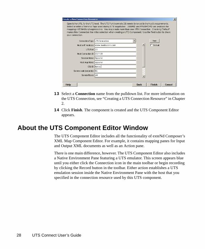
12 Click Next. The Connection Info panel of the Create a New UTS Component Wizard appears.
UTS Connect User’s Guide28
13 Select a Connection name from the pulldown list. For more information on the UTS Connection, see “Creating a UTS Connection Resource” in Chapter 2.
14 Click Finish. The component is created and the UTS Component Editor appears.
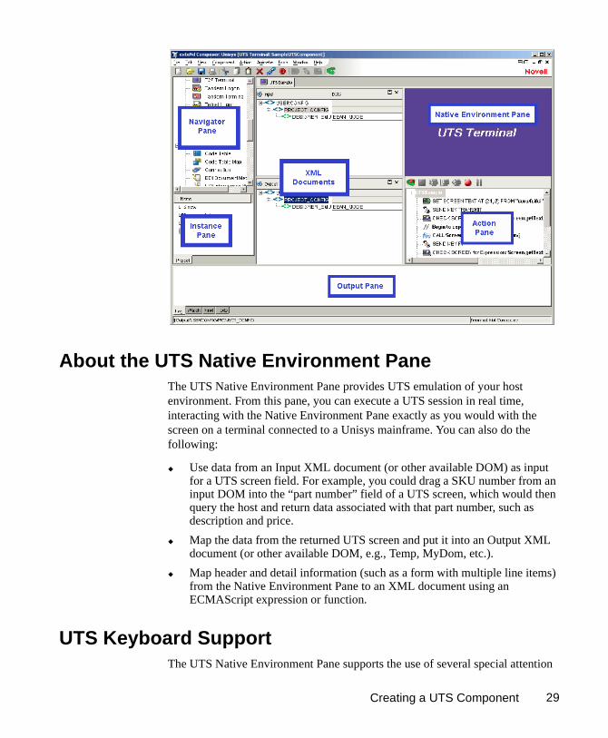
About the UTS Component Editor WindowThe UTS Component Editor includes all the functionality of exteNd Composer’s XML Map Component Editor. For example, it contains mapping panes for Input and Output XML documents as well as an Action pane.
There is one main difference, however. The UTS Component Editor also includes a Native Environment Pane featuring a UTS emulator. This screen appears blue until you either click the Connection icon in the main toolbar or begin recording by clicking the Record button in the toolbar. Either action establishes a UTS emulation session inside the Native Environment Pane with the host that you specified in the connection resource used by this UTS component.
Creating a UTS Component 29
About the UTS Native Environment PaneThe UTS Native Environment Pane provides UTS emulation of your host environment. From this pane, you can execute a UTS session in real time, interacting with the Native Environment Pane exactly as you would with the screen on a terminal connected to a Unisys mainframe. You can also do the following:
Use data from an Input XML document (or other available DOM) as input for a UTS screen field. For example, you could drag a SKU number from an input DOM into the “part number” field of a UTS screen, which would then query the host and return data associated with that part number, such as description and price.
Map the data from the returned UTS screen and put it into an Output XML document (or other available DOM, e.g., Temp, MyDom, etc.).
Map header and detail information (such as a form with multiple line items) from the Native Environment Pane to an XML document using an ECMAScript expression or function.
UTS Keyboard SupportThe UTS Native Environment Pane supports the use of several special attention

UTS Connect User’s Guide30
keys including: Clear Home, Local, Previous Page, Specify, Forms Mode Toggle, Next Page, Receive and Transmit. The function for each attention key may vary depending on the host application. These keys are mapped to the PC Keyboard as follows:
You can either use the keys directly from the keyboard as you create your UTS Component, or you can use a keypad tool bar available from the view menu.
How to Use the Floating Keypad:
1 Select View/Terminal Keypad from the Composer Menu. A floating Keypad appears.
Table 1-1:
UTS Key PC Key UTS Key PC Key
MsgWait Ctrl + W F11 F11
SOE Ctrl + S F12 F12
Transmit Enter F13 Shift + F1
UnlckKbd Esc F14 Shift + F2
F1 F1 F15 Shift + F3
F2 F2 F16 Shift + F4
F3 F3 F17 Shift + F5
F4 F4 F18 Shift + F6
F5 F5 F19 Shift + F7
F6 F6 F29 Shift + F8
F7 F7 F21 Shift + F9
F8 F8 F22 Shift + F10
F9 F9 F23 Shift + F11
F10 F10 F24 Shift + F12

Creating a UTS Component 31
2 Click on the key you wish to invoke. If you require help, hover the mouse over that key. Help will display the UTS keyboard equivalent for that key. You will see the result of the key you clicked in the Native Environment Pane.
3 Click OK to close the keypad. In order for the keypad to redisplay, you must repeat step 1.
About the Screen ObjectThe Screen Object is a byte-array representation of the emulator screen shown in the Native Environment Pane, with methods for manipulating the screen contents.
What it is
The UTS component communicates with the host environment via the block mode terminal data stream , in a UTS session. A block of data essentially represents a screen. The host sends a screen block that is displayed in the component. The screen is edited by the user (and ultimately by the component you create) and the modified screen block is sent back to the host for processing after you press an attention key. The Screen Object represents the current screen’s block of data. For a 24 x 80 terminal screen, this is 1,920 bytes of data.
How it works
When character data arrives from the host, appropriate updates to the Native
UTS Connect User’s Guide32
Environment Pane occur in real time. Those updates might be anything from a simple cursor repositioning to a complete repaint of the terminal screen. The screen content is, in this sense, highly dynamic.
When you have signaled exteNd Composer (via a Set Screen Text action) that you wish to operate on the current screen’s contents, the screen buffer is packaged into a Screen Object that is made accessible to your component through ECMAScript.
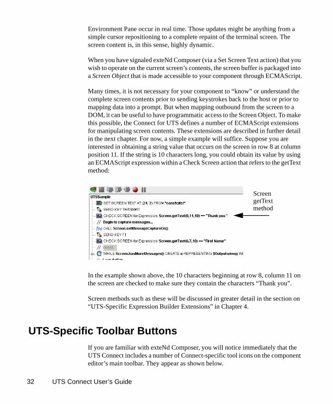
Many times, it is not necessary for your component to “know” or understand the complete screen contents prior to sending keystrokes back to the host or prior to mapping data into a prompt. But when mapping outbound from the screen to a DOM, it can be useful to have programmatic access to the Screen Object. To make this possible, the Connect for UTS defines a number of ECMAScript extensions for manipulating screen contents. These extensions are described in further detail in the next chapter. For now, a simple example will suffice. Suppose you are interested in obtaining a string value that occurs on the screen in row 8 at column position 11. If the string is 10 characters long, you could obtain its value by using an ECMAScript expression within a Check Screen action that refers to the getText method:
In the example shown above, the 10 characters beginning at row 8, column 11 on the screen are checked to make sure they contain the characters “Thank you”.
Screen methods such as these will be discussed in greater detail in the section on “UTS-Specific Expression Builder Extensions” in Chapter 4.
UTS-Specific Toolbar ButtonsIf you are familiar with exteNd Composer, you will notice immediately that the UTS Connect includes a number of Connect-specific tool icons on the component editor’s main toolbar. They appear as shown below.
ScreengetText method

Creating a UTS Component 33
Record Button
Record icon (normal state)
Record icon (recording in progress)
Record icon (disabled)
The Record button allows you to capture keyboard and screen manipulations as you interact with the Native Environment Pane. Recorded operations are placed in the Action Model as actions, which you can then “play back” during testing.
Connection Button
Connection (disconnected state)
Connection (connected state)
Connection (connected/disabled state)
The Connection button on Composer’s main toolbar toggles the connection state of the component (using settings you provided during the creation of the Connection Resource associated with the component).
NOTE: When you are recording or animating, a connection is automatically established, in which case the button will be shown in the “connected/disabled” state. When you turn off recording, the connection the button will return to the enabled state.
Set Screen Text Button
The Set Screen Text button on exteNd Composer’s main toolbar is used to indicate that you wish to send data to the screen object. Clicking this button will brings up the Set Screen Text dialog, allowing you to create
a new Set Screen Text Action.. (See the next chapter for a detailed discussion of this action type.)

UTS Connect User’s Guide34
Send Key Button
The Send Key button on Composer’s main toolbar would be pressed when you wish to add a Send Key Action to the Action Model. (See the next chapter for a detailed discussion of this action type.) The various
UTS attention keys are discussed in the section above entitled “UTS Keyboard Support”.
Create Check Screen Button
The Create Check Screen button on Composer’s main toolbar is used to check that the terminal screen is in the state you expect it to be. Clicking this button will brings up the Check Screen dialog, allowing you to
create a new Check Screen Action. (The next chapter contains a detailed discussion of this action type.)
UTS-Specific Menu Bar Items
Component MenuTwo additional items have been added to the Component drop down menu for the UTS Connect. These are Start/Stop Recording and Connect/Disconnect (depending on your current status).
Start/Stop Recording—This menu option manages the automatic creation of actions as you interact with a host program. Start will enable the automatic creation of actions as you interact with the screen and Stop will end action creation.
Connect/Disconnect—This menu option allows you to control the connection to the host. When you are recording or animating, a connection is automatically established (and consequently, the connection icon is shown in the “connected/disabled” state). However, this menu choice is useful if you are not recording and you merely want to establish a connection for the purpose of navigating the UTS environment.
UTS-Specific Context-Menu ItemsThe UTS Connect also includes context-menu items that are specific to this Connect. To view the context menu, place your cursor in either the Native Environment pane or the Action pane and click the right mouse button.

Creating a UTS Component 35
Native Environment Pane Context Menu
When you right-mouse-click in the Native Environment Pane, you will see a contextual menu. The menu items will be greyed out if you are not in record mode. In record mode, the context menu has the following appearance:
The four commands work as follows:
Set Screen Text: USERID—Automatically sends User ID information to the host, based on the value you supplied (if any) for User ID in the UTS Connection Resource for this component. Also creates the corresponding Set Screen Text action in the Action Model.
Set Screen Text: PASSWORD—Automically transmits Password information to the host, based on the Password you supplied (if any) in the UTS Connection Resource for this component. Also creates the corresponding Set Screen Text action in the Action Model.
Set Screen Text...—Creates a new Set Screen Text dialog, allowing you to create a new Set Screen Text Action. (See the next chapter for a detailed discussion of the use of this command).
Check Screen...—Brings up the Check Screen dialog, allowing you to create a new Check Screen Action. (This will be discussed in greater detail in the next chapter.)
Action Pane Context Menu
If you click the right mouse button when the mouse is located anywhere in the Action pane, a context menu appears as shown.

UTS Connect User’s Guide36
The UTS-specific functions of the context menu items are as follows:
Set Screen Text—Allows you to create a Set Screen Text action to send data to the host. A dialog appears, allowing you to specify what you want to send to the host as well as determining the screen position where the information will be received. (See the next chapter for a detailed discussion of the use of this command.)
Check Screen— Allows you to create a new Check Screen action which is used to make sure the appropriate screen is present before the component continues processing. A dialog appears, allowing you to specify various go-ahead criteria as well as a Timeout value. (The next chapter contains a detailed discussion of the Check Screen action.)

37
4
Performing Basic UTS Actions
Performing Basic UTS Actions Chapter 4
About ActionsAn action is similar to a programming statement in that it takes input in the form of parameters and performs specific tasks. Please see the chapters in the Composer User's Guide devoted to Actions.
Within the UTS Component Editor, a set of instructions for processing XML documents or communicating with non-XML data sources is created as part of an Action Model. The Action Model performs all data mapping, data transformation, data transfer between hosts and XML documents, and data transfer within components and services.
An Action Model is made up of a list of actions that work together. As an example, you might design an Action Model that would read some invoice data from a file and then transform the data in some way before placing it in an output XML document.
The Action Model mentioned above would be composed of several actions. These actions would:
Use an XML document containing a sku number as input to perform a UTS transaction which retrieves the invoice data for that sku from an inventory database that resides on your Unisys host
Map the result to a temporary XML document
Convert a numeric code using a Code Table
Map the result to an Output XML document
About UTS-Specific ActionsAs mentioned in the previous chapter, the UTS Connect includes three actions that are specific to the UTS environment: Set Screen Text, Send Key and Check Screen.

UTS Connect User’s Guide38
The purpose of these actions is to allow the UTS component (running in a deployed service) to replicate, at runtime, the terminal/host interactions that occur in a UTS session. The usage and meanings of these actions are described in further detail below.
The Set Screen Text Action
The Set Screen Text action encapsulates “keystroke data” (whether actually obtained from keystrokes, or through a drag-and-drop mapping, or via an ECMAScript expression built with the Expression Builder) that will be sent to the host in a single transmission at component execution time. When the Set Screen Text action executes, the data will appear on the host system screen. The data will not, however, be sent to the host until an attention key of some sort is sent using the Send Key Action..
The Set Screen Text action can be created in several ways:
In Record mode, just begin typing on the Native Environment Pane. Keystrokes are automatically captured to a new Set Screen Text action.
Right-mouse-click anywhere in the Action Model; a contextual menu appears. Select New Action and Set Screen Text.
UTS Action Description
Set Screen Text Allows the user to specify what data is transmitted to the host and at what screen position it will be received. The string is formed from Map actions, user keystrokes or it may come from an ECMAScript Expression. The Set Screen Text action can be created manually, but will more often be generated automatically when the user types into the screen or maps data to the current prompt.
Send Key Sends a UTS-specific attention key to the host system. The Send Key action can be created manually by clicking an icon, or automatically when the user presses one of the mapped keys or selects it from the UTS keypad.
Check Screen Allows the component to stay in sync with the host application. This action signals the component that execution must not proceed until the screen is in a particular state (which can be specified in the Check Screen setup dialog), subject to a user-specified timeout value.

Performing Basic UTS Actions 39
In the main menu bar, under Action, select New Action and Set Screen Text.
To create a Set Screen Text action using menu commands:
1 Right-mouse-click anywhere in the Action Model and select New Action, then Set Screen Text, from the contextual menu (or use the Action menu as described above). The Set Screen Text dialog will appear.
2 To map a DOM element’s contents to the buffer, click the XPath radio button, then select a DOM from the pulldown list and type the appropriate XPath node name in the text area (or click the Expression icon at right and build the node name using the Expression Builder).
3 To specify the buffer’s contents using ECMAScript, click the Expression radio button, as shown on the screen above, then use the Expression Builder dialog to create an ECMAScript expression that evaluates to a string.
4 To specify the Row at which to receive data, type a value in the field. By default, the number you type will be a constant. The down arrow next to the k (constant) allows you to toggle back and forth between entering a constant and an ECMAScript expression.
5 To specify the Column at which to receive data, type a value in the field. By default, the number you type will be a constant. The down arrow next to the k (constant) allows you to toggle back and forth between entering a constant and an ECMAScript expression
6 Click OK.
NOTE: When a Set Screen Text action is created automatically for you while recording your session, all of your subsequent keystrokes will be captured to the buffer until you press an attention key or select one from the Send Key dialog.

UTS Connect User’s Guide40
The Send Key Action
The Send Key action does simply that - it sends an attention key to the host. This action will generally follow a Set Screen Text action so that the information you wish to transmit to the host gets there. When the Send Key action executes, the data you specified in the Set Screen Text action are actually transmitted to the host. Some Send Key actions, of course, stand alone and can be pressed at any time to receive specific information, clear the screen or navigate to different areas.
The Send Key action can be created in several ways:
In Record mode, press one of the PC keys designated as an attention key (see the previous chapter for a discussion of these keys) to have the attention key executed at the current cursor position.
From the drop down menu, select View, Terminal Keypad, click on an attention key and click OK to have the attention key executed at the current cursor position.
Click on the Send Key icon in the main toolbar to bring up the Send Key dialog box.
To create a Send Key action using the main toolbar icon:
1 With focus on the action after which you would like your Send Key action to appear, click on the Send Key icon in the main toolbar. The Send Key dialog will appear.
2 From the Key Value drop down, select the attention key you would like to send to the host. Remember that the function for each attention key may vary depending on the host application.

Performing Basic UTS Actions 41
3 If you wish the key to execute at a position other than the current row/column location, check the Override Cursor Position box. This will enable the Row and Column position fields.
4 To specify the Row at which to transmit the key, type a value in the field. By default, the number you type will be a constant. Alternatively, you can click on the Expression builder to enter the row in the form of an ECMAScript expression.
5 To specify the Column at which to transmit the key, type a value in the field. By default, the number you type will be a constant. Alternatively, you can click on the Expression builder to enter the column in the form of an ECMAScript expression.
6 Click OK.
The Check Screen Action
Because of the latency involved in UTS sessions and the possibility that screen data may arrive in an arbitrary, host-application-defined order, it is essential that your component can depend on the terminal screen being in a given state before it operates on the current screen data. The Check Screen action makes it possible for your component to stay “in sync” with the host. You will manually create Check Screen actions at various points in your Action Model so that precisely the correct screens are acted on at precisely the right time(s).
To create a new Check Screen action, you can do one of the following:
Click on the “Create Check Screen Action” button on the main toolbar, or
Perform a right mouse click inside the action list, then select New Action and Check Screen from the contextual menu, or
In the component editor’s main menu bar, select Action, then New Action, then Check Screen
While you are in Record mode, with your cursor in the Native Environment Pane, right-click then select Check Screen.
NOTE: You will most often use the toolbar button when you are in Record mode.
To create a Check Screen action using a menu command:
1 With your cursor positioned in the Action Model on the action item after which you want your new item to appear, perform a right mouse click. Then select New Action and Check Screen from the contextual menu (or use the Action menu in the main menu bar as described above). The Check Screen dialog appears.

UTS Connect User’s Guide42
2 Specify a Screen Wait value in seconds. (See discussion below.)
3 Specify a Screen Evaluation Expression by typing one in directly or clicking on the Expression Builder icon to create one. (See discussion below.)
4 Click OK.
Understanding the Check Screen Action
It is important that the execution of actions in your Action Model not proceed until the host application is ready, and all screen data have arrived (that is, the screen is in a known state).
Your component must have some way of “knowing” when the current screen is ready. The Check Screen Action is how you specify the readiness criteria.
The purpose of the Check Screen Action dialog is twofold:
It allows you to specify a wait time for program synchronization.
It allows you to specify an expression which will be used as a criterion to judge whether the screen is in a state of readiness at execution time.
Screen Wait
The Screen Wait value (in seconds) represents the maximum amount of time that your component will wait for screen data to arrive and meet the readiness criterion specified in the expression. If the available screen data do not meet the readiness criteria before the specified number of seconds have elapsed, an exception is thrown.

Performing Basic UTS Actions 43
NOTE: Obviously, since the latency involved in a UTS session can vary greatly from application to application, from connection to connection, or even from screen to screen, a great deal of discretion should be exercised in deciding on a Screen Wait value. Careful testing of the component at design time as well as on the server will be required in order to determine “safe” Screen Wait values.
The default Screen Wait value is determined by what you entered when setting up your UTS Connection Resource.
Expression
To determine your “go-ahead” criterion, you can click the Expression radio button in the Check Screen Action dialog and enter an ECMAScript expression in the associated text field. The expression you create will usually check on the existence of some specific data at a location in the Screen Object buffer. At runtime, if the expression evaluates as “true,” the screen will be considered ready; but not otherwise. An example of such an expression would be: Screen.getText(1,11,4) == “MARC”
Expressions are discussed in detail below.
Using Actions in Record Mode
The easiest way to create an Action Model for your component is to use Record mode. When you build an Action Model in this way, a new Set Screen Text action is created for you automatically as soon as you begin typing or drag an element from the Input DOM into the appropriate field onscreen. All you need then do is send the appropriate attention key, wait for the next screen to arrive from the host, add a Check Screen action to make sure you are on the right screen and begin the process again, repeatedly. In this fashion, a sequence of Set Screen Texts, Send Keys and Check Screens actions can be built very quickly and naturally.
Working in record mode will be discussed further in Chapter 5, in the section entitled “Recording a UTS Session.”
UTS-Specific Expression Builder ExtensionsThe Connect for UTS exposes several UTS-specific ECMAScript variables and object extensions, which are visible in Expression Builder picklists. The UTS-specific items are listed under the node labelled “UTS.” There are two child nodes: Login and Screen Methods. See illustration below.

UTS Connect User’s Guide44
Login
UTS Connection Resources have two global variables that are accessible from Expression Builder dialogs: USERID and PASSWORD. These properties (available under the Login node of the UTS picktree) specify the User ID and Password values that may be requested by the host system when you connect. You can map these variables into the terminal screen, which eliminates the need for typing user and password information explicitly in a map action.
NOTE: You can also create a Set Screen Text action where the XPath source is defined as $PASSWORD.
Screen Methods
When an Expression Builder window is accessed from a Map or Function action in the UTS Component, the picklists at the top of the window expose special UTS-specific ECMAScript extensions, consisting of various methods of the Screen object.
Hover-help is available if you let the mouse loiter over a given picktree item. (See illustration.)
UTS-specific
picktree nodes

Performing Basic UTS Actions 45
In addition, you can obtain more complete online help by clicking Help in the lower left corner of the dialog.
The Screen object offers methods with the following names, signatures, and usage conventions:
getAttribute( nRow, nColumn )
Returns datatype: int
This method returns the display attribute value of the character at the screen position given by aRow, aColumn. The complete set of possible display attribute values is listed in “UTS Display Attributes”. An example of using this method is:
if (Screen.getAttribute( 5, 20 ) == 34) // if character at row 5, col 20 is protected and bold
... // do something
getCursorCol( void )
Returns datatype: int
This method returns the current column position of the cursor in the UTS emulator screen (Native Environment Pane). Column positions are one-based rather than zero-based. In other words, in 24x80 mode, this method would return a value from 1 to 80, inclusive.

UTS Connect User’s Guide46
getCursorRow( void )
Returns datatype: int
This method returns the current row position of the cursor in the UTS emulator screen (Native Environment Pane). Row positions are one-based rather than zero-based. In other words, in 24x80 mode, this method would return a value from 1 to 24, inclusive.
getCols( void )
Returns datatype: int
This method returns the native horizontal dimension of the current screen. (Due to possible mode changes in the course of host-program execution, this value can change from screen to screen. Do not depend on this value staying constant over the life of the component.) When a program is in 24x80 mode, this method will return 80. To loop over all columns of a screen, regardless of its native dimensions, you could do:
for (var i = 1; i <= Screen.getCols(); i++)
{
var myCol = Screen.getTextAt( i, 1, Screen.getCols() );
// do something with myCol
}
getNextMessage( void )
Returns datatype: string
The result of this method, when placed in a variable, returns the string representing the next captured message. The setMessageCaptureOn() method (see below) must be set in order for this method to return anything. In addition to these, there are two other messaging methods: hasMoreMessages() and setMessageCaptureOff(). Below is an example demonstrating how the four of them might all be used together:
function msgChecker(theScreen)
{
theScreen.setMessageCaptureOn();
while (theScreen.hasMoreMessages())
{
alert(theScreen.getNextMessage());
}
Performing Basic UTS Actions 47
theScreen.setMessageCaptureOff();
}
getPrompt( void )
Returns datatype: string
The result of this method, when placed in a variable, returns the string representing all characters in the cursor’s row, starting at column 1 and continuing to, but not including, the value returned by getCursorCol()—in other words, everything from the beginning of the line to the current cursor position. As an example:
var prompt=Screen.getPrompt();
alert(prompt);
NOTE: The string returned may or may not actually be a host prompt.
getRows( void )
Returns datatype: int
This method returns the native vertical dimension of the current screen. (Due to possible mode changes in the course of host-program execution, this value can change from screen to screen. Do not depend on this value staying constant over the life of the component.) When a program is in 24x80 mode, this method will return 24. To loop over all rows of a screen, regardless of its native dimensions, you could do:
for (var i = 1; i <= Screen.getRows(); i++)
{
var myRow = Screen.getText( i, 1, Screen.getRows() );
// do something with myRow
}
var wholeScreen = Screen.getText( 1, 1 + 24 * 80 ); // ERROR!
getStatusLine( void )
Returns datatype: string
The result of this method, when placed in a variable, returns an ECMAScript String that represents the black status line at the bottom of the Native Environment Pane. This status line is only enabled following a Check Screen action.
If you wished to create an alert stating the current status of the screen, for example, you could create a function action like the following:

UTS Connect User’s Guide48
var screenStatus = Screen.getStatusLine( );
alert(screenStatus);
getText( nRow, nColumn, nLength )
Returns datatype: String
This method returns an ECMAScript String that represents the sequence of characters (of length nLength) in the current screen starting at the row and column position specified. Note that nRow and nColumn are one-based, not zero-based. A zero value for either of these parameters will cause an exception.
To put the first half of the 20th row of a 24x80 screen into a variable, you would do:
var myRow = Screen.getText( 20, 1, 40 );
The getText() technique is used internally both for drag-and-drop Map actions involving screen selections (described in “Selecting Continuous Data” further below) and in the Check Screen action.
NOTE: If the amount of data selected by the function's arguments goes past the end of a screen line, no newlines or other special characters are inserted into the string.
getTextFromRectangle(nStartRow, nStartColumn,nEndRow, nEndColumn)
The getTextFromRectangle() method returns a single String consisting of substrings (one per row) comprising all the characters within the bounding box defined by the top left and bottom right row/column coordinates specified as parameters. So for example, in 24x80 mode, you could obtain the upper left quarter of the screen by doing:
var topLeftQuadrant = Screen.getTextFromRectangle(1,1,12,40);
The getTextFromRectangle() method is used internally in drag-and-drop Map actions involving rectangular screen selection regions created using the Shift-selection method (see“Selecting Rectangular Regions” below).
Note that the string returned by this method contains newline delimiters between substrings. That is, there will be one newline at the end of each row’s worth of data. The overall length of the returned string will thus be the number of rows times the number of columns, plus the number of rows. For example, Screen.getTextFromRectangle(1,1,4,4).length will equal 20.
Performing Basic UTS Actions 49
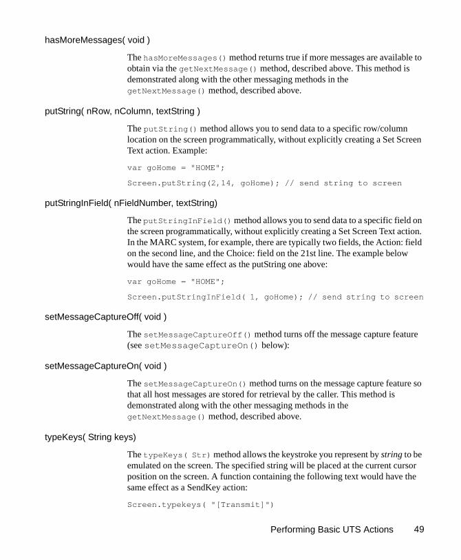
hasMoreMessages( void )
The hasMoreMessages() method returns true if more messages are available to obtain via the getNextMessage() method, described above. This method is demonstrated along with the other messaging methods in the getNextMessage() method, described above.
putString( nRow, nColumn, textString )
The putString() method allows you to send data to a specific row/column location on the screen programmatically, without explicitly creating a Set Screen Text action. Example:
var goHome = "HOME";
Screen.putString(2,14, goHome); // send string to screen
putStringInField( nFieldNumber, textString)
The putStringInField() method allows you to send data to a specific field on the screen programmatically, without explicitly creating a Set Screen Text action. In the MARC system, for example, there are typically two fields, the Action: field on the second line, and the Choice: field on the 21st line. The example below would have the same effect as the putString one above:
var goHome = "HOME";
Screen.putStringInField( 1, goHome); // send string to screen
setMessageCaptureOff( void )
The setMessageCaptureOff() method turns off the message capture feature (see setMessageCaptureOn() below):
setMessageCaptureOn( void )
The setMessageCaptureOn() method turns on the message capture feature so that all host messages are stored for retrieval by the caller. This method is demonstrated along with the other messaging methods in the getNextMessage() method, described above.
typeKeys( String keys)
The typeKeys( Str) method allows the keystroke you represent by string to be emulated on the screen. The specified string will be placed at the current cursor position on the screen. A function containing the following text would have the same effect as a SendKey action:
Screen.typekeys( "[Transmit]")

UTS Connect User’s Guide50
Multi-row Screen Selections in the UTS ConnectIn record mode, it is possible to select multiple rows of data in a continuous stream, for purposes of dragging out to a DOM.
Selecting Continuous Data
When you drag across multiple rows of data without holding the Shift key down, all characters from the initial screen offset (at the mouse-down event) to the final screen offset (at mouse-up) are selected, as shown in the graphic below. (The selected text is “reversed out.” A partial row has been selected, followed by two complete rows, followed by another partial row.
You will notice that as you drag, the component editor window’s status line in the lower left-hand corner reports the beginning and ending rows and columns of your selection. If, while in Record mode, you were to drag this selection out of the Native Environment Pane, into a DOM, a Map action would be generated as follows:
Notice that the getText() method is used. This means the captured screen characters form one string, which is mapped to Output/SCREENINFO/Screen1. No newlines or other special characters are inserted into the string. (Any blank spaces highlighted in darker blue on the screen shown are simply represented as space characters in the string.)
Performing Basic UTS Actions 51
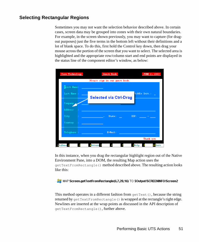
Selecting Rectangular Regions
Sometimes you may not want the selection behavior described above. In certain cases, screen data may be grouped into zones with their own natural boundaries. For example, in the screen shown previously, you may want to capture (for drag-out purposes) just the five terms in the bottom left without their definitions and a lot of blank space. To do this, first hold the Control key down, then drag your mouse across the portion of the screen that you want to select. The selected area is highlighted and the appropriate row/column start and end points are displayed in the status line of the component editor’s window, as below:
In this instance, when you drag the rectangular highlight region out of the Native Environment Pane, into a DOM, the resulting Map action uses the getTextFromRectangle() method described above. The resulting action looks like this:
This method operates in a different fashion from getText(), because the string returned by getTextFromRectangle() is wrapped at the rectangle’s right edge. Newlines are inserted at the wrap points as discussed in the API description of getTextFromRectangle(), further above.

UTS Connect User’s Guide52

53
5
UTS Components in Action
UTS Components in Action Chapter 5
The Sample TransactionFor demonstration purposes, this guide uses a simple demo interface offered for demonstration purposes by a third party. The transactions shown here in the form of screen captures will be representative of the type of transactions commonly used by operators on UTS terminals. Unlike the exercises in the Composer Tutorial, these steps are not meant to be followed by the user, but are merely given here for illustrative purposes.
Recording a UTS SessionThe UTS Component differs from other components in that a major portion of the Action Model is built for you automatically. This happens as you interact with the host in the Native Environment pane as part of a live UTS session. Composer records your interactions as a set of auto-generated actions in the Action Model. Typically, in other exteNd Composer components (such as a JDBC Component), you must manually create actions in the Action Model, which then perform the mapping, logging, transformation, communication, and other tasks required by the component or service. By contrast, when you create a UTS Component, you record requests and responses to and from the host, which end up as actions in the Action Model. In addition, you can add standard actions (Map, Log, Function, etc.) to the Action Model just the same as in other components.
NOTE: In order to successfully build a UTS Component, you should be familiar with the specifics of the host application you intend to use in your XML integration project.
The following example demonstrates several common tasks that you will encounter in building UTS Components, such as:
Automatic creation of Set Screen Text actions
UTS Connect User’s Guide54
Automatic creation of Send Key actions
Automatic creation of Check Screen actions
Drag-and-drop mapping of Input DOM elements to UTS-screen prompts
Drag-and-drop mapping from the Native Environment Screen to the Output DOM
The use of ECMAScript expressions to manipulate Screen object elements
The following example starts with an XML document that contains several parameters used as input to a guest book page. The goal of this particular component is simply to sign a guest book on the demo system and receive some information back from the terminal. Several screen messages will be placed in the Output DOM.
To record a UTS session:
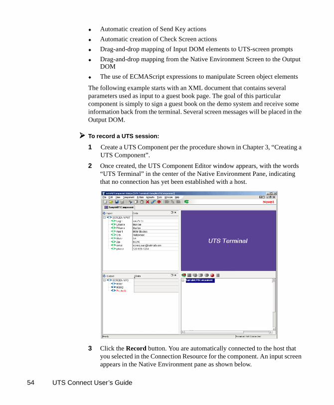
1 Create a UTS Component per the procedure shown in Chapter 3, “Creating a UTS Component”.
2 Once created, the UTS Component Editor window appears, with the words “UTS Terminal” in the center of the Native Environment Pane, indicating that no connection has yet been established with a host.
3 Click the Record button. You are automatically connected to the host that you selected in the Connection Resource for the component. An input screen appears in the Native Environment pane as shown below.

UTS Components in Action 55
4 Begin by checking the screen to make sure you have arrived at the expected place. This should always be the first action when you arrive at a new screen in a UTS Component (or any terminal component for that matter). To do this, use the left button on your mouse to highlight some text on the native environment panel and then right click and select Check Screen. The Check Screen dialog window appears, with an expression already entered as shown below:
5 Click OK and the Check Screen action is added to the action model.

UTS Connect User’s Guide56
6 Reposition your cursor to the space just after the arrow prompt in the Native Environment pane. In this UTS application, exact placement in the entry fields is important. Drag the SCREENPUT/Login node from the Input DOM to the second column of the 24th row of the Native Environment Pane. You will notice when you drag the item that the text appears after the arrow prompt and a new Set Screen Text action appears automatically in the Action Model.
7 Position your cursor after the text that was entered and press the Enter Key. You will see that a Send Key Transmit Action is added to your Action Model and the screen changes in response.
UTS Components in Action 57
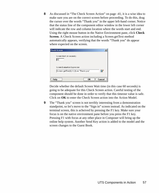
8 As discussed in “The Check Screen Action” on page -41, it is a wise idea to make sure you are on the correct screen before proceeding. To do this, drag the cursor over the words “Thank you” in the upper left-hand corner. Notice that the status line of the component editor window in the lower left corner will indicate the row and column location where the words start and end. Using the right mouse button in the Native Environment pane, click Check Screen. A Check Screen action including a Screen.getText method automatically appears, verifying that the words “Thank you” do appear where expected on the screen.
Decide whether the default Screen Wait time (in this case 60 seconds) is going to be adequate for this Check Screen action. Careful testing of the component should be done in order to verify that this timeout value is safe. Click on OK to enter the Check Screen action into the Action Model.
9 The “Thank you” screen is not terribly interesting from a demonstration standpoint, so let’s move to the “Sign in” screen instead. As indicated on the terminal screen, this is acheived by pressing the F1 key. Make sure your focus is on the native environment pane before you press the F1 key. Pressing F1 with focus at any other place in Composer will bring up the online help system. Another Send Key action is added to the model and the screen changes to the Guest Book.

UTS Connect User’s Guide58
10 As always, verify that you are on the correct screen. Highlight the word “Guest Book” and right click to select Check Screen. Click OK to add this action to the Action Model.
11 Now, instead of having to type the information into the guest book, you can use the data that already exists in your Input DOM and map it to appropriate fields in the Native Environment Pane. From the input DOM, drag the SCREENINPUT/LName node into the “Last Name:” field on the terminal screen. Again, as you click and drag, the onscreen row/column coordinates of the selected area are displayed in the status line and a new Set Screen Text action appears in the model
12 Proceed by dragging all the remaining nodes from the Input DOM into the appropriate fields on Guest Book screen. The Sign-in screen will begin to look filled out, and several new Set Screen Text actions will appear in your action model.

UTS Components in Action 59
13 After signing the guest book, proceed with the rest of the Demo by pressing F1 again, which changes the screen and adds another Send Key Transmit action to the model.
14 As always, it is a good idea to make sure you are on the expected screen, so highlight the screen text “Background/Foreground” and right click to create another Check Screen Action. The Screen and Action model now look like this:
15 Next, drag some information from the screen into the Output DOM. Highlight and drag the first paragraph on the terminal screen into the MSG1 node. Drag the second paragraph into the MSG2 node. The following actions are added and the Output DOM now looks like this:

UTS Connect User’s Guide60
16 Now, use the Ctrl-Drag method to map the produts shown on the screen into the Product node of the Output DOM. Placing the cursor on the left-most character of the top product in the list, hold down Ctrl and the left mouse key and drag to the bottom, right-most character of the product list. The following action is added to the model:
The SCREENINFO/Products Node of the output DOM will now contain the list of products from the terminal screen.
17 Click the Record button to turn recording off.
18 Save your component.
If you were sucessfully able to follow all the steps outlined above, your complete Action Model would now look like this:

UTS Components in Action 61
Obviously, this is a fairly simple component.that does not accomplish much real work. In using Composer to build UTS components, your initial recorded component may only be a starting point. For this reason, it is important to study how to edit existing action models.
Editing a Previously Recorded Action ModelYou will encounter times when you need to edit a previously recorded action model. Unlike the situation with other components, editing a UTS Component requires extra attention. When a UTS Component executes, it plays back a sequence of actions that expect certain screens and data to appear at certain times in order to work properly. So when editing a component you must be careful not to make the action model sequence inconsistent with the host program execution sequence you recorded earlier (i.e., don’t break it!).
In general, to ensure successful edits, the following recommendations apply:
Exercise extreme care when using Cut, Copy, and/or Paste to delete, move, or replicate actions in your Action Model. Actions that were created automatically during a “Record” session will often create data dependencies that are easily overlooked in the editing process.
When you need to use drag-and-drop to add new Map actions to your Action Model, click the Start Animation button in the Action Pane toolbar and step to the line of interest in your Action Model; then Pause animation and turn on Record mode. At this point, you can safely drag to and from the screen. Following this procedure will prevent your Action Model from getting out of sync with the host or conflicting with previously mapped DOM data.
Editing or Adding to an Existing Action
The following procedure will explain how to change an existing action or add new actions to a previously recorded session.
To Change an existing action in a previously recorded Action Model:
1 Open the component that includes the Action Model you'd like to edit. The component appears in the UTS Component Editor window.

UTS Connect User’s Guide62
2 Navigate to the action in the Action Model where you’d like to make your edit or after which you’d like to add additional actions and highlight that action.

UTS Components in Action 63
3 Click the Toggle Breakpoint button (or press F2). The highlighted action becomes red (Animation will be discussed in further detail below).
4 Click the Start Animation button. The animation tools (in the Actions pane’s toolbar) become enabled.
5 Click the Step to Breakpoint/End button. The Action Model executes all of the actions from the beginning of the Action Model to the breakpoint you set in step 3 above.
Start Animation
Toggle Breakpoint
Step to Breakpoint/End

UTS Connect User’s Guide64
6 Press the Pause Button:
7 In the Component Editor tool bar, click the Record button.
Pause
Record button

UTS Components in Action 65
8 Edit the action to make any changes you wish to the current line by right-clicking on the action and selecting Edit Action. Or, if you wish to add new actions, use Composer's drag and drop features to add new Map actions that interact with the screen. The new actions will be added directly under the highlighted line.
9 Turn off recording. (Toggle the Record button.)
10 Test your component.
Deleting an Action
The following procedure explains how to delete an action in a previously recorded session
To Delete an Action to a previously recorded Action Model:
Highlight the action line that you want to delete and click on the right mouse button. Select Delete from the menu. You may also highlight the line and press the Delete button on your keyboard.
Looping Over Multiple Rows in Search of Data
In the example above, the goal was to sign a guest book and place some information from the terminal into the Output DOM.

UTS Connect User’s Guide66
One of the items mapped was the product list. In real life, in order to map something like a product list, you would want to have each product map into its own node in an Output DOM. This requires an iterative loop, for example a Repeat/While loop, which is explained in detail in Chapter 8 of the Composer User Guide in the section titled “The Repeat While Action.” Often, in UTS components you will find that you need to perform some form of looping in order to read the values from the terminal window. Make sure you are very familiar with this chapter of the User Guide.
Below is an example of a completed Action Model containing a Repeat/While loop that fills in an Output DOM with several values obtained from the terminal window. In the example above, you used drag and drop to place all the values from the Product List into a single pre-existing node in the Output DOM. Here, each product has been placed in it’s own node along with some sub-nodes which could also be used as attributes.
Testing your UTS ComponentAs mentioned previously, Composer includes animation tools that allow you to easily test your component. There is also an Execution button on the UTS Component Editor tool bar, which allows you to execute the entire Action Model

UTS Components in Action 67
and verify that your component works as you intend. While testing, pay close attention to your Screen Wait Time values in all Check Screen actions to make sure they are appropriate and that Set Screen Text and other actions work as intended.
To execute a UTS Component:
1 Open a UTS Component. The UTS Component Editor window appears.
2 Select the Execute button. All the actions in the Action Model execute in order. This is an excellent way to determine whether the Screen Wait times you indicated in your Check Screen Actions are accurate or if you require additional Check Screens in your Model. If the component executes successfully, a message appears as follows.
Execute button

UTS Connect User’s Guide68
3 Click OK.
After executing the component, you may want to double check the contents of your DOMs to be sure all of the appropriate data mappings occurred as expected. To make all data elements visible, select Expand XML Documents from the View menu. This expands all of the parents, children, data elements, etc. of the DOM trees, so that you can easily see the results of execution of the component. If your execution had a problem, you can use the Animation tools to pinpoint where the difficulty occurred. This process is described in the next section.
Using the Animation ToolsIn the Action Model, you'll find animation tools that allow you to test a particular section of the Action Model by setting one or more breakpoints. The Toggle/Breakpoint tool was introduced briefly in the section above, “Editing or Adding to an Existing Action” on page -61, but all the animation tools will be explored in more detail below. Using these tools, you can run through the actions that work properly, stop at the actions that are giving you trouble, and then troubleshoot the problem actions one at a time.
The following procedure is a brief example of the functionality of the animation tools. For a complete description of all the animation tools and their functionality, please refer to the exteNd Composer User's Guide.
To run a UTS Component using Animation Tools:
1 Open a UTS Component. The component appears in the UTS Component Editor window.
NOTE: Animation and Recording are mutually exclusive modes in the component. In order to record during animation, you must either pause, or stop animation and then turn on record mode.
2 Click the Start Animation button in the Action Model tool bar, or press F5 on the keyboard. All of the tools on the tool bar become active, and a connection is established with the host. The Native Environment Pane makes the terminal connection..
3 Click the Step Into button. The first Check Screen action becomes highlighted.
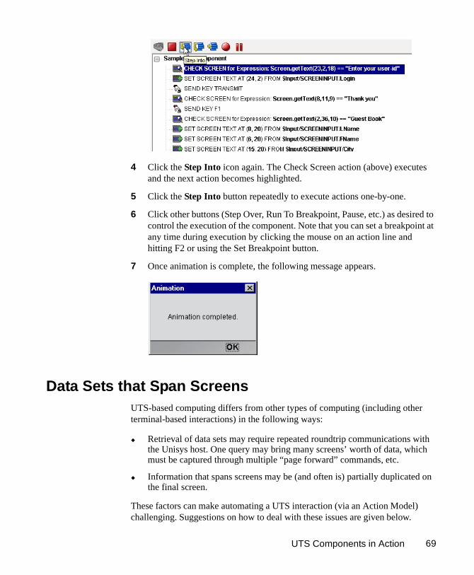
UTS Components in Action 69
4 Click the Step Into icon again. The Check Screen action (above) executes and the next action becomes highlighted.
5 Click the Step Into button repeatedly to execute actions one-by-one.
6 Click other buttons (Step Over, Run To Breakpoint, Pause, etc.) as desired to control the execution of the component. Note that you can set a breakpoint at any time during execution by clicking the mouse on an action line and hitting F2 or using the Set Breakpoint button.
7 Once animation is complete, the following message appears.
Data Sets that Span ScreensUTS-based computing differs from other types of computing (including other terminal-based interactions) in the following ways:
Retrieval of data sets may require repeated roundtrip communications with the Unisys host. One query may bring many screens’ worth of data, which must be captured through multiple “page forward” commands, etc.
Information that spans screens may be (and often is) partially duplicated on the final screen.
These factors can make automating a UTS interaction (via an Action Model) challenging. Suggestions on how to deal with these issues are given below.
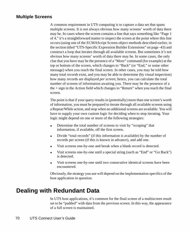
UTS Connect User’s Guide70
Multiple Screens
A common requirement in UTS computing is to capture a data set that spans multiple screens. It is not always obvious how many screens’ worth of data there may be. In cases where the screen contains a line that says something like “Page 1 of 4,” it’s a straightforward matter to inspect the screen at the point where this line occurs (using one of the ECMAScript Screen-object methods described earlier, in the section titled “UTS-Specific Expression Builder Extensions” on page -43) and construct a loop that iterates through all available screens. But sometimes it’s not obvious how many screens’ worth of data there may be. In some cases, the only clue that you have may be the presence of a “More” command (for example) at the top or bottom of the screen, which changes to “Back” (or “End,” or some other message) when you reach the final screen. In other cases, you may be told how many total records exist, and you may be able to determine (by visual inspection) how many records are displayed per screen; hence, you can calculate the total number of screens of information awaiting you. There may be the presence of a the + sign in the Action field which changes to “Return” when you reach the final screen.
The point is that if your query results in (potentially) more than one screen’s worth of information, you must be prepared to iterate through all available screens using a Repeat/While action, and stop when no additional screens are available. You will have to supply your own custom logic for deciding when to stop iterating. Your logic might depend on one or more of the following strategies:
Determine the total number of screens to visit by “scraping” that information, if available, off the first screen.
Divide “total records” (if this information is available) by the number of records per screen (if this is known in advance), and add one.
Visit screens one-by-one and break when a blank record is detected.
Visit screens one-by-one until a special string (such as “End” or “Go Back”) is detected.
Visit screens one-by-one until two consecutive identical screens have been encountered.
Obviously, the strategy you use will depend on the implementation specifics of the host application in question.
Dealing with Redundant DataIn UTS host applications, it’s common for the final screen of a multiscreen result set to be “padded” with data from the previous screen. In this way, the appearance of a full screen is maintained.

UTS Components in Action 71
Consider the following two screen shots. The top one shows the first screen’s worth of information after transmitting a command that returns two screens of information. Notice the + sign in the Action field of the first screen indicating that there is more data to follow.
Pressing the Transmit Key (or Enter), brings up the second screen. There are several things to notice about this second (and, in this case, final) screen:
The + sign in the Action: field has been replaced by the word “REturn”. Sending the Transmit Key here would return you to the Job and Task Display Menu.
The second screen shows exactly the same records as the first one, except for job number 2111/2111, which drops off to make room for four of the 1621 jobs because the second screen is limited to listing 17 lines of jobs. (The first screen had only 14 lines of data, because there were three lines worth of header information). The majority of this screen is showing us redundant data.
Another + sign appears on the screen, this time in marking the fourth-to-last job on the screen. The system provides us with a convenient way to see where the list splits and where the data ceases to be redundant.

UTS Connect User’s Guide72
In most cases, you will not want to capture this sort of redundant data. Fortunately, the demo system used here has made it fairly simple to detect and reject redundant records by placing the + sign at the first column to the left in the list where the data begins to be new. This can be used along with ECMAScript as an easy and convenient way of maintaining unduplicated lists. The basic steps to do this would be:
Enter a Repeat/While loop checking the name of the screen.
Create a Switch Statement depending on whether the screen is continued or not.
Within each case of the Switch Statement, enter a Repeat While loop and fetch each record to place it into a variable as shown in the example above.
After the loop is complete, send a Transmit Key to go on to the next screen.
Tips for Building Reliable UTS ComponentsThe following tips may be helpful to you in building reliable UTS Components.
Always follow a Set Screen Text Action with a Send Key Action.
Always follow your Send Key Actions with a Check Screen Action.
Remember that the default Screen Wait values used in Check Screen actions are set when you initially created your Connection resource. To change the default Screen Wait time, you must change the property of the Connection Resource.
Remember also that Screen Wait timeout values may need to be increased, for load-sensitive applications. Careful testing will reveal these sorts of problems.
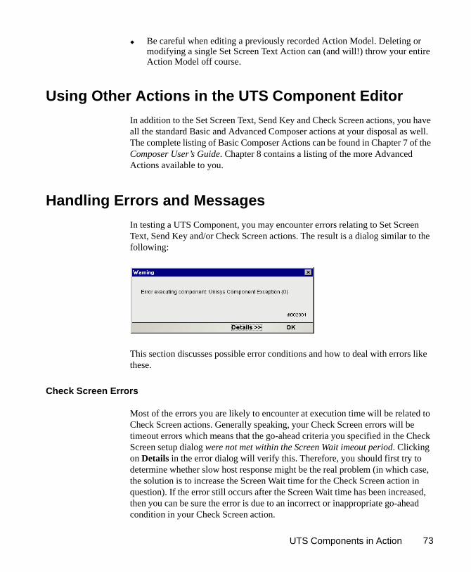
UTS Components in Action 73
Be careful when editing a previously recorded Action Model. Deleting or modifying a single Set Screen Text Action can (and will!) throw your entire Action Model off course.
Using Other Actions in the UTS Component Editor
In addition to the Set Screen Text, Send Key and Check Screen actions, you have all the standard Basic and Advanced Composer actions at your disposal as well. The complete listing of Basic Composer Actions can be found in Chapter 7 of the Composer User’s Guide. Chapter 8 contains a listing of the more Advanced Actions available to you.
Handling Errors and Messages
In testing a UTS Component, you may encounter errors relating to Set Screen Text, Send Key and/or Check Screen actions. The result is a dialog similar to the following:
This section discusses possible error conditions and how to deal with errors like these.
Check Screen Errors
Most of the errors you are likely to encounter at execution time will be related to Check Screen actions. Generally speaking, your Check Screen errors will be timeout errors which means that the go-ahead criteria you specified in the Check Screen setup dialog were not met within the Screen Wait imeout period. Clicking on Details in the error dialog will verify this. Therefore, you should first try to determine whether slow host response might be the real problem (in which case, the solution is to increase the Screen Wait time for the Check Screen action in question). If the error still occurs after the Screen Wait time has been increased, then you can be sure the error is due to an incorrect or inappropriate go-ahead condition in your Check Screen action.

UTS Connect User’s Guide74
“Screen Check Expression {0} was evaluated as false”
This error happens when the ECMAScript expression you used for your Check Screen go-ahead happens to evaluate as false at execution time. Once again, it’s important to realize that this sort of error can be triggered simply on the basis of slow host response (timeout). When the host is slow to respond, it means that your ECMAScript expression will be evaluated on the basis of whatever is in the screen buffer as of the moment of timeout. If no data (or insufficient data) have arrived, the expression is bound to evaluate as false.
To fix this sort of problem, either increase the Screen Wait time for this Check Screen action (if you suspect that the problem is host latency) or try modifying the logic in your ECMAScript expression.
Set Screen Text Errors
Errors generated by Composer from Set Screen Text action will, in general, be rare. This is because you are given a great deal of leeway in your ability to send whatever you like to the screen. Where you will more often run into trouble is on the application side. Unisys hosts are very particular about the input they will accept. If the text you send in your Set Screen Text action is not what the host expects, you will receive host-side errors and the rest of your Composer Action model will not proceed as expected.The way to avoid problems here is to make sure that for every Set Screen Text/Send Key action combination, there is always a corresponding Check Screen action.
Finding a “Bad” ActionWhen you have a large Action Model (containing dozens or hundreds of Set Screen Text, Send Key and Check Screen actions), simply locating the action that’s responsible for an error can be a challenge. One way to find the problematic action is to:
1 Select and Copy some of the text in the error dialog. (Click the Details button if need be, to expose the full error description. Highlight the relevant text, such as cursor coordinates. Then use Control-C to Copy.)
2 Click inside the Action Model.
3 Use Control-F to initiate a search.
4 Paste the error text into the search dialog.
5 Execute the search.

UTS Components in Action 75
Of course, if you have multiple Check Screen actions that are based on identical go-ahead criteria, the foregoing technique won’t necessarily be helpful. If that’s the case, set a breakpoint at the midpoint of your Action Model, and run the component. If the error doesn’t occur, move the breakpoint to a spot halfway between the original breakpoint and the end of the action list. (Otherwise, if the error does happen, set the breakpoint at a spot one quarter of the way down from the top of the action list.) Run the component again. Keep relocating the breakpoint, each time halving the distance between the last breakpoint or the top or bottom of the action list, as appropriate. In this way, you can quickly narrow down the location of the problematic action. (Using this “binary search” strategy, you should be able to debug an Action Model containing 128 actions in just 7 tries.)
Performance ConsiderationsYou can perform second-based timing of your Action Model’s actions by wrapping individual actions (or block of actions) in timing calls.
To time an Action:
1 Click into the Action Model and place a new Function Action immediately before the action you wish to time. (Right-mouse-click, then New Action > Function.)
2 In the Function Action, enter an ECMAScript expression of the form:
startTime = Number(new Date)
3 Insert a new Function Action immediately after the action you wish to time.
4 In the Function Action, enter an ECMAScript expression of the form:
endTime = Number(new Date)
5 Create a Map Action that maps endTime – startTime to a temporary DOM element. (Right-mouse-click, New Action > Map.)
6 Run the Component. (Click the Execute button in the main toolbar.)
If you do extensive profiling of your Action Model, you will probably find that the overwhelming majority of execution time is spent in Check Screen actions. Two implications of this worth considering are:
ECMAScript expressions (in Map and/or Function actions) will seldom, if ever, be a performance consideration for the component as a whole.
Overall component performance rests on careful tuning of Screen Wait timeout values in Check Screen actions.
UTS Connect User’s Guide76
Finally, remember that testing is not truly complete until the deployed service has been tested (and proven reliable) on the app server.
For additional performance optimization through the use of shared connections, be sure to read the next chapter on Logon Components.

77
6
Logon Components, Connections, and Connection Pools
Logon Components, Connections, and Connection Pools Chapter 6
This section discusses certain features available in the UTS Connect designed to maximize performance of deployed services.
About UTS Terminal Session PerformanceThe overall performance of any service that uses back-end connectivity is usually dependent on the time it takes to establish a connection and begin interacting with the host. Obtaining the connection is “expensive” in terms of wait time. One strategy for dealing with this is connection pooling, a scheme whereby an intermediary process (whether the app server itself, or some memory-resident background process not associated with the server) maintains a set number of preestablished, pre-authenticated connections, and oversees the “sharing out” of these connections among client apps or end users.
Connection pooling overcomes the latency involved in opening a connection and authenticating to a host. But in terminal-based applications, a considerable amount of time can be spent “drilling down” through menu selections and navigating setup screens in order to get to the first bonafide application screen of the session. So even when connections are reused through pooling, session-prolog overhead can be a serious obstacle to performance.
Composer addresses these issues by providing connection pooling, managed by a special kind of component (called a logon component) that can maintain an open connection at a particular “drill-down” point in a terminal session, so that clients can begin transactions immediately at the proper point in the session.
When Will I Need Logon Components?
Logon Components are useful in several types of situations:

UTS Connect User’s Guide78
When you have a need for multiple tiers of pooling based on multiple security challenges within your system. (For example, users may need one set of logon credentials to get into the network, another to get into the mainframe, and another to get into database.) Serial log-in requirements may dictate the use of multiple logon components.
When your service needs stateful “session-based” connections.
When you need the performance advantages available through connection pooling.
If performance under load is not a high-priority issue and your connectivity needs are relatively uncomplicated, you may not need to use Logon Components at all. But there is no way to know if performance is adequate merely by testing services at design time, on a desktop machine.
Components and services built with the UTS Component Editor may appear to execute quickly at design time (in Animation Mode, for example). But in real-world conditions—which is to say under load, with dozens or even hundreds of requests per second arriving at the server—session overhead can be a significant factor in overall transaction time. The only way to know whether you need to use the special performance enhancement features described in this chapter is to do load testing on a server, under test conditions that mimic real-world “worst case” conditions.
Connection Pool Architecture
When you install the Connect for UTS, three types of Connection Resources are added to the Connection creation wizard:
UTS Connection
a UTS MultiBridge Connection
UTS Logon Connection (henceforth referred to as a Logon Connection)
The UTS MultiBridge Connection is a server version that minimizes the number of connections going back to the host and also contains added security. The UTS Connection is a true terminal connection and (when used by a UTS component) can establish a session with a host system. This is the connection-type that has been throughout this Guide.

Logon Components, Connections, and Connection Pools 79
The UTS connection resource is designed to make an individual connection to the host on an as-needed basis. The connection is made just-in-time and discarded as soon as the client is done. It is not reused in any way.
The Logon Connection, on the other hand, is different. It defines a pool of User IDs and passwords, each of which can make its own connection. The Logon Connection also serves as an indirection layer to allow clients to connect to the host at exactly the point in the host program (exactly the screen) where the client needs to start. This entry-point-location behavior is made possible by the Logon Component. (A Logon Connection always uses a Logon Component to get to the actual connection.) The architecture is shown in the graphic below.

UTS Connect User’s Guide80
A Connection Resource is always required in order to get to the host. (This is true for any Composer service that uses UTS components.) For simplicity, this diagram shows the Connection Resource going directly to the host; in the real world, there may be intervening delegation layers for security purposes.
The Logon Component contains Actions (an action model) designed to find a particular screen of interest in the host program. This drill-down location is the effective entry point of the transaction for any upstream process that uses this Logon Component. You can think of the Logon Component as a go-between between the physical connection (represented by the Connection Resource) and the logic layer (represented by the UTS Component itself.
In order for a UTS Component (at the top of the diagram) to use a Logon Component, it needs to enlist the aid of a Logon Connection resource. The Logon Connection is the bridge between the UTS Component and the Logon Component.
The kinds and responsibilities of the various objects discussed above are summarized in the following table.
Object Role
UTS Connection Resource
Allows a connection to be established with a host system.
Logon Component Specialized type of component in which the action model contains Logon, Keep Alive, and Logoff action blocks. This component can maintain a connection at a particular launch screen in a host program.
Logon Connection Specialized type of Connection Resource that associates a pool of UserIDs and passwords with a given Logon Component type. At runtime, connections are established for client processes on demand (and reused), with one Logon Component instance per connection. Every connection in the pool provides ready access to a given point (a particular launch screen) in the host program, thanks to the associated Logon Component (see above).
UTS Terminal Component
Contains the action model that comprises the business logic for a particular UTS interaction (or transaction).

Logon Components, Connections, and Connection Pools 81
The Logon Connection’s Role in Pooling
The Logon Connection differs from the ordinary “host-direct” connection resource in that it manages pooling (the sharing of connection instances and Logon Component instances at runtime).
In the context of a Composer service, pooling not only allows reuse of (open) connections at runtime, it also increases the effective bandwidth of a deployed service. Consider the simple case where you’ve designed a UTS component that uses a regular connection resource. In creating the connection resource, you will have specified a UserID and password for the resource to use so that at runtime, the component can log in to the host. When an actual running instance of your component is using that connection, no other instance of the component can log in to the host using that same set of credentials. The bandwidth of your service is limited to one connected instance at a time.
With a Logon Connection, on the other hand, numerous host connections can be maintained in a “live” state so that multiple instances of your component can access the host (each on its own connection) without waiting. Throughput is dramatically increased.
The diagram below shows one possible runtime case where three component instances (two instance of UTS Terminal Component A and one instance of UTS Terminal Component B) are executing on the server. Instance 1 of Component A is using UserID ‘E’ to obtain a connection. This component has its own dedicated instances of Logon Component M and Connection S.
Terminal Component B has just finished executing and is relinquishing its connection (established through credentials defined by UID ‘F’). Note that because connection pooling is in effect, Component B’s downstream resources (its Logon Component instance, M2, and its Connection instance, S2) are not simply discarded; they remain live. As a result, Terminal Component A2 is able to obtain (reuse) the M2/S2 resource instances that were previously held byTerminal Component B.

UTS Connect User’s Guide82
In this diagram, Logon Connection D is associated with four connections based on four UIDs (user IDs or credentials: A-thru-F). One is in use; another (UID ‘F’) is alive but not being used; and two are inactive but available (i.e., valid UIDs have been assigned, so these two connections can be made live at any time).
How Many Pools Do I Need?
It’s possible for several different UTS components to draw from the same connection pool. It’s also possible for different components to draw from different pools. This means different Logon Connections.
An important factor in deciding how many Logon Connection resources (in effect, how many pools) your service needs is the number of different start screens (or entry point screens) needed by the various components in your project. Suppose Terminal Component A needs to begin its work at a particular starting screen in a host application, but you’ve also designed another component—Terminal Component B—that needs to start on a different screen. Components A and B will need separate Logon Connections, and the separate Logon Connections will point to separate Logon Components. (In any given connection pool, Composer objects are shared in such a way that every user of the pool must start at the same screen.)
Pieces Required for Pooling
The combination of a Logon Connection, a Logon Component, and its Connection Resource form the basis of a connection pool. Starting from the host layer and working up the chain:
The Connection Resource defines the most basic parameters necessary for establishing a connection with the Unisys host. When connection pooling is in effect, runtime instances of this object are kept alive and reused.
The Logon Component defines the set of steps (actions) necessary to get to a particular entry point in the host program. (At runtime, an instance of this component will actually carry out those steps in order to arrive at, and maintain ready-to-use, a particular screen location in the host program.) When connection pooling is in effect, instances of this object are kept alive and reused.
The Logon Connection is a special type of resource that contains all the information needed to define a connection pool. This resource is designed to encapsulate pool-management info and does not establish host connections directly; instead, it delegates those responsibilities to the Logon Connection (which delegates them, in turn, to the appropriate Connection Resource).

Logon Components, Connections, and Connection Pools 83
How Do I Implement Pooling?To create the various pieces required for pooling, you’ll go through the following basic steps (each of which will be discussed in greater detail in the sections to follow):
1 First, you’ll create a basic UTS connection resource, as demonstrated in Chapter 2 of this Guide.
2 Next, you’ll create a Logon Component that uses the connection resource defined in Step 1. As part of this process, you’ll create an action model designed to navigate to a certain point in the host program.
3 You will create a Logon Connection resource, which is a specialized type of connection resource that relies on a Logon Component (from Step 2) to make the basic connection (through the resource defined in Step 1).
4 Finally, you’ll create a UTS Terminal Component and associate it with the Logon Connection resource of Step 3.
These steps are described in detail starting with the discussion in “Creating a Connection Pool” further below. Before going to that section, however, you should become familiar with the design principles behind the Logon Component (and also the Logon Connection). We’ll start with the Logon Component, since it’s impossible to create a Logon Connection without using a Logon Component.
The UTS Logon ComponentThe Logon Component is a special type of component: It has an Action Model, yet can be used as a connection resource as well. The Action Model of this type of component is designed to manage a connection that will be used by multiple UTS Terminal Components. In most respects, the Logon Component is the same as a UTS Terminal component. The differences are:
1 In a Logon Component, the Action Model is organized around connection-management tasks. Those tasks are implemented via special actions: the Logon Action, KeepAlive Action, and Logoff Action.
2 A Logon Component is not invoked directly by another component or service. Its invocation is under the control of a Logon Connection.
NOTE: A Logon Component must and can only be used in conjunction with a Logon Connection.

UTS Connect User’s Guide84
Instead of calling the Logon Component directly, using (for example) a Component Action, you will associate the Logon Component with a special connection resource called a Logon Connection. When your UTS Terminal Component executes, it executes via the Logon Connection, which in turn executes the Logon Component.
Logon, Keep Alive, and Logoff Actions
The Logon Component provides several screen-management capabilities that are important factors in overall performance. These capabilities are implemented in terms of Logon, Keep Alive, and Logoff actions:
Logon Actions—These actions navigate through the host environment and park at a desired launch screen in the host system. The connection is activated using UserIDs from the pool. The UTS Terminal components that subsequently reuse the connection have the performance benefit of already being at the launch screen and won’t incur the overhead of navigating to the launch screen as if they had come in under their own new session.
Keep Alive Actions—These actions do two important tasks. First, they prevent the host from dropping a connection if it is not used within a standard timeout period defined by the host. Second, these actions must insure that the connection is always positioned at the “launch screen in the host, even after performing the Keep Alive actions needed to prevent the connection from dropping (the first important task).
Logoff Actions—These actions exit the host environment in a manner you prescribe for all the connections made by User IDs from the pool, when a connection is being terminated.
These actions and their meanings will be discussed in greater detail below. For now, it’s enough to know that these three action groupings are created for you automatically when you first create a Logon Component. Note the (empty) Logon, Keep Alive, and Logoff action blocks in the action model shown below:
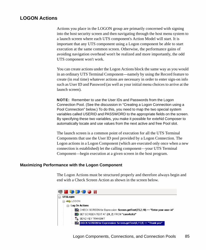
Logon Components, Connections, and Connection Pools 85
LOGON Actions
Actions you place in the LOGON group are primarily concerned with signing into the host security screen and then navigating through the host menu system to a launch screen where each UTS component's Action Model will start. It is important that any UTS component using a Logon component be able to start execution at the same common screen. Otherwise, the performance gains of avoiding navigation overhead won't be realized and more importantly, the odd UTS component won't work.
You can create actions under the Logon Actions block the same way as you would in an ordinary UTS Terminal Component—namely by using the Record feature to create (in real time) whatever actions are necessary in order to enter sign-on info such as User ID and Password (as well as your initial menu choices to arrive at the launch screen).
NOTE: Remember to use the User IDs and Passwords from the Logon Connection Pool. (See the discussion in “Creating a Logon Connection using a Pool Connection” below.) To do this, you need to map the two special system variables called USERID and PASSWORD to the appropriate fields on the screen. By specifying these two variables, you make it possible for exteNd Composer to automatically locate and use values from the next active and free Pool slot.
The launch screen is a common point of execution for all the UTS Terminal Components that use the User ID pool provided by a Logon Connection. The Logon actions in a Logon Component (which are executed only once when a new connection is established) let the calling component—your UTS Terminal Component—begin execution at a given screen in the host program.
Maximizing Performance with the Logon Component
The Logon Actions must be structured properly and therefore always begin and end with a Check Screen Action as shown in the screen below.

UTS Connect User’s Guide86
The final Check Screen action in the Logon block guarantees that control is not turned over to the UTS Component before the screen of interest has arrived in the connection. Without this, the UTS Component could start at an invalid screen, throw an exception, and possibly corrupt a transaction.
NOTE: You may notice when animating a Logon Component that the ending Check Screen is skipped. This is normal design-time behavior. In a production environment , the actions in a Logon Component always execute in an interleaved manner with a UTS Terminal Component. Animating a Logon Component from start to finish actually creates an abnormal sequence of events that would result in two Check Screens being processed in succession, which is not allowed.
The performance benefit comes into play as a result not only of connection reuse but launch-screen reuse. For example, if a User ID pool of three entries is fully used and (ultimately) reused by the execution of a component fifteen times, the overhead of navigating to a menu item that executes the transaction of interest will occuro nly three times. Likewise, there will only be three logons to the host because the Logon actions at the top of a Logon Component are executed only once—when a new connection is activated (not when it is reused). This is key to obtaining maximum performance in a high-transaction-volume production settings.
NOTE: When possible, use the Try/On Error action to trap potential logon errors that may be recoverable. Otherwise, the UserID trying to establish the failed logon will be discarded from the pool, decreasing the potential pool size. The pool size will remain smaller until you manually reset the discarded connections using the exteNd Composer Enterprise Server Console for UTS. Refer to “Managing Pools” in this Chapter for more details.
Keep Alive Actions
The KEEP ALIVE block is where you will place actions that “ping the host” in whatever way necessary to keep the connection alive so that it can be reused.
Keep Alive actions usually involve sending an Attention key, such as <Transmit>, to the host at some specified interval. However, if after sending the Attention key the screen changes to some screen that is different than the launch screen, you must be sure to return the Logon Component to the launch screen in the Keep Alive section. Failure to do so will leave the next component at an incorrect screen, causing it to fail.
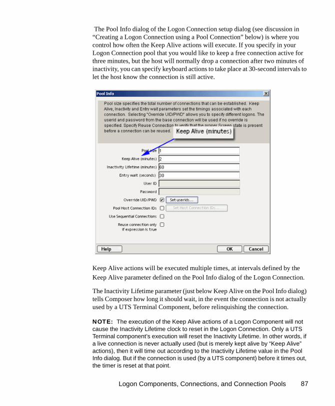
Logon Components, Connections, and Connection Pools 87
The Pool Info dialog of the Logon Connection setup dialog (see discussion in “Creating a Logon Connection using a Pool Connection” below) is where you control how often the Keep Alive actions will execute. If you specify in your Logon Connection pool that you would like to keep a free connection active for three minutes, but the host will normally drop a connection after two minutes of inactivity, you can specify keyboard actions to take place at 30-second intervals to let the host know the connection is still active.
Keep Alive actions will be executed multiple times, at intervals defined by the
Keep Alive parameter defined on the Pool Info dialog of the Logon Connection.
The Inactivity Lifetime parameter (just below Keep Alive on the Pool Info dialog) tells Composer how long it should wait, in the event the connection is not actually used by a UTS Terminal Component, before relinquishing the connection.
NOTE: The execution of the Keep Alive actions of a Logon Component will not cause the Inactivity Lifetime clock to reset in the Logon Connection. Only a UTS Terminal component’s execution will reset the Inactivity Lifetime. In other words, if a live connection is never actually used (but is merely kept alive by “Keep Alive” actions), then it will time out according to the Inactivity Lifetime value in the Pool Info dialog. But if the connection is used (by a UTS component) before it times out, the timer is reset at that point.

UTS Connect User’s Guide88
The last action inside a Keep Alive block should be an empty but “enabled” navigation action. If a user disables this last action, animation will not work properly due to two consecutive empty navigation actions occurring. For example, if an action in Logon and the first action in Keep Alive are disabled, an error occurs.
Maximizing Performance with Keep Alive Actions
Check Screen actions must occur at the beginning and end of the Keep Alive section.
Not only must the Keep Alive section prevent the connection from closing, but it must make sure that the proper launch screen is present when the execution is completed. Therefore, the first Check Screen checks to make sure that during the time the connection was available but not in use, an unexpected screen didn’t arrive from the host. The ending Check Screen prevents the premature release of the connection to the next UTS Component. See below for a typical Keep Alive block.
Logoff Actions
Logoff actions essentially navigate the User ID properly out of the host system after a timeout.
Logoff actions execute once for a given connection, and only when a connection times out (i.e. the Inactivity Lifetime expires) or the connection is closed via the UTS Server console.
Logon Components, Connections, and Connection Pools 89
In a “best practices” sense, it’s vitally important to make Logoff Actions bulletproof. If an exception occurs during execution of the Logoff actions, exteNd Composer will break its connection with the host, freeing the UserID in the pool. But the UserID may still be active on the host. Until the host kills the UserID (from inactivity), a subsequent attempt by the pool to log on with that UserID may fail, unless you’ve coded your logon to handle the situation. Logon failures cause the UserID to be discarded from the pool, reducing the potential pool size and performance overall. As with Logon and Keep Alive actions, the way to guarantee you are on the proper screen at the end of the logoff is to end with a Check Screen.
Logon Component Life Cycle
Each time a User ID is activated from the Logon Connection Pool, an instance of the corresponding Logon Component is created and associated with that User ID. Then the Logon actions are executed until the desired launch screen is reached. At this point the UTS Terminal component execution begins. When it is finished another UTS Terminal component using the same Logon Connection may begin executing, starting at the same launch screen.
If no other component requests the connection, then the connection-instance in question enters an active but free state (an “idle state”) defined by the Inactivity Lifetime and KeepAlive settings on the Pool Info dialog of the Logon Connection. If the Keep Alive period (e.g., 2 minutes) is shorter than the Inactivity Lifetime (e.g., 120 minutes), then at appropriate (2-minute) intervals, the Keep Alive actions will be executed, preventing a host timeout and dropped connection; and the Keep Alive Period begins anew.
A Logon Component’s execution lifetime is dependent on the activity of the Logon Connection that uses it. As long as one entry in the Logon Connection pool is active, then one instance of the Logon Component will be in memory in a live state. A Logon Component instance will go out of scope (cease executing) when the last remaining pool entry expires due to inactivity. The only other way to stop execution of a Logon Component is through the UTS Console on the Server.

UTS Connect User’s Guide90
About the UTS Logon Connection
The Logon Connection is not a true connection object like a UTS Connection Resource, but a pointer to a Logon Component (which in turn connects to a host either through a conventional Connection Resource or yet more intervening Logon Connection/Logon Component pairs). The Logon Connection encapsulates information needed to describe a pool of connections. That includes User IDs and passwords, plus pool settings involving the time interval between retries on discarded connections, etc. Another function of the Logon Connection is that it ensures the use of different instances of the same Logon Component for all the User IDs for which connections are made.
The dialogs you’ll use in setting up a pool of User IDs for a Logon Connection are shown in the following set of illustrations. Arrows denote the buttons that lead to continuation dialogs.

Logon Components, Connections, and Connection Pools 91
Every Logon Connection is associated with a given Logon Component. In addition, the Logon Connection provides the following User ID pool functionality:
1 It allows the specification of multiple User IDs in advance ensuring that clients are able to secure a connection when one is needed
2 It allows the reuse of a User ID/connection once it is established to eliminate repeated user authentications and disconnects
3 It allows a single User ID to use multiple connections if this is supported by the host system
4 It keeps a connection active to prevent host timeouts during inactive periods
5 It lets you specify when to remove a connection from the active pool
6 It sets a timeout period to use for a fully active pool to provide a free connection
7 It lets you specify error handling dependent on the state of the Logon Component used by the Logon Connection
Many-to-One Mapping of Components to Logons
In order for multiple instances of a UTS Terminal component or different UTS Terminal components to use a the same Logon Connection, the following conditions must be met:
1 All the UTS Terminal components must use the same Connection Resource (thereby sharing the Unisys Host, Port and data encoding parameters)
2 All the UTS Terminal components must have a common launch screen in the host system from which they can begin execution (see “Creating a Logon Component” below for more detail).
Connection Pooling with a Single Sign-On
If your host system security supports multiple logins from a single user ID, you may have circumstances where you wish to pool the single User ID. This can be accomplished by performing the following steps:
Specify a User ID/Password in the Connection Resource used by the Logon Component.
On the Pool Info dialog of the Logon Connection, specify a Pool Size greater than 1.
Do NOT check the Override the UID/PWD setting in the Pool Info dialog of the logon Connection.

UTS Connect User’s Guide92
These steps will cause each pool slot to use the User ID and Password contained in the Connection object and not use the user IDs from the pool.
Creating a Connection Pool
Overview
When creating a UTS Terminal component, you normally first create the Connection object it needs first. Similarly, when creating the objects comprising a Connection Pool, you must create certain objects first, starting (in essence) at the host and working your way backwards to the UTS Terminal Component that will access the host.
A typical sequence of steps for creating a Connection Pool is:
Creating a Basic UTS ConnectionThis step is simple. Create a new Connection Resource as described in “Creating a Basic UTS Connection” on page -92. Even though you will be using User IDs and Passwords defined in the Logon Connection later, you should still define one in the Connection as well. This will be needed when you define the Logon Component in the next step. Alternatively, you can simply use an existing Connection Resource.
Step One: Create a basic host
Connection Resource
Step Two:Create Logon Component that uses basic Connection
Step Three:Create Logon Connection
that uses Logon Component
Step Four:Create standard Components
using Logon Connection

Logon Components, Connections, and Connection Pools 93
Creating a Logon Component
To create a UTS Logon Component:
1 From the Composer File menu, select New>xObject, then open the Component tab and select UTS Logon.
The Header Info panel of the New xObject Wizard appears.
2 Type a Name for the connection object.
3 Optionally, type Description text.
4 Click Next and the Connection Info panel appears.
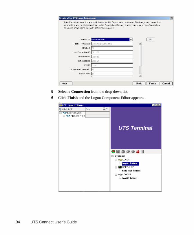
UTS Connect User’s Guide94
5 Select a Connection from the drop down list.
6 Click Finish and the Logon Component Editor appears.

Logon Components, Connections, and Connection Pools 95
NOTE: Recording actions follows a series of steps. The cursor must be positioned over LOGON; turn Record on, and when you are done, turn Record off. Position the cursor to KEEP ALIVE, turn Record on, and when you are done, turn Record off. Position the cursor to LOGOFF, turn Record on, then when you are done, turn Record off.
7 Record Logon Actions for logging into the host and navigating to the launch screen using the same Recording techniques described in Chapter 5 of this Guide.
8 Edit the Logon Map actions that enter a User ID and Password to instead use the special USERID and PASSWORD variables described in the section titled “UTS-Specific Expression Builder Extensions” on page -43 of this Guide.
9 Create the needed Check Screen and Send Key actions in the KEEPALIVE section of the Action Model (a quick way to do this is to copy an existing action, highlight the appropriate action, paste, and then modify if necessary).
10 Record LOGOFF actions for properly exiting the host
11 Save and close the logon Component.
Creating a Logon Connection using a Pool Connection
To create a UTS Logon Connection:
1 From the Composer File menu, select New>xObject, then open the Resource tab and select Connection, or you can click on the icon. The Header Info panel of the New xObject Wizard appears.

UTS Connect User’s Guide96
2 Type a Name for the connection object.
3 Optionally, type Description text.
4 Click Next and the Connection Info panel appears.
5 For the Connection Type select "UTS Logon Connection" from the drop down list.
6 In the Logon Via control, select the Logon Component you just created.
7 Click on the Pool Info button and the Pool Info dialog appears.

Logon Components, Connections, and Connection Pools 97
8 Enter a Pool Size number. This represents the total number of connections you wish to make available in this pool. For each connection, you will be expected to supply a UserID/Password combination later.
9 Enter a KeepAlive time period. This number represents (in minutes) how often you wish to execute the Keep Alive actions in the associated Logon Component whenever the connection is active but free (i.e. not being used by a UTS component). The number you enter here should be less than the Screen Wait Timeout period defined on the host for an inactive connection.
10 Enter an Inactivity Lifetime. This number represents (in minutes) how long you wish to keep an active free connection available before closing out the connection and returning it to the inactive portion of the connection pool. Remember, that once the connection is returned to its inactive state in the pool, it will incur the overhead of logging in and navigating host screens when it is re-activated.
11 Enter an Entry Wait time in seconds. This time represents how long a UTS component will wait for a free connection when all the pool entries are active and in use. If this time period is reached, an Exception will be thrown to the Application Server.
12 Enter a Userid and Password if desired.

UTS Connect User’s Guide98
13 Checking Override UID/PWD means you wish to specify User ID/Password combinations for use in the connection pool. When checked,
this activates the Set Userids button. Click on the button to display the Set USERIDs and PASSWORDS dialog.
On the Toolbar there are three icons: Add which adds an empty row, Delete, which deletes a highlighted row and Paste which allows you to copy/paste information from a spreadsheet into the table. For more on this, see the following Note.
NOTE: Alternate and faster ways to enter data are to copy data from a spread sheet and paste it into the table. Make sure your selection contains two columns. The first column must contain UserID; the second Password. Open the spreadsheet, copy the two columns and as many rows as needed. Open the table and immediately press the Paste icon located on the toolbar. You can also copy data from tables in a Microsoft Word® document using the same technique.
14 Enter as many USERID/PASSWORD combinations until you reach the size of the pool you specified and click OK. Pool size will be adjusted depending
upon how many rows you entered.
15 Click OK to dismiss the “Set User IDs and Passwords” dialog and return to the Pool Info dialog.
16 Optionally click the Pool Host Connection IDs checkbox in the Pool Info dialog if you intend to manage terminals by identifier strings. When checked, this activates the Set Host Connection IDs button. Click on the button to display the dialog.
Paste
Add
Delete

Logon Components, Connections, and Connection Pools 99
On the Toolbar there are three icons: Add which adds an empty row, Delete, which deletes a highlighted row and Paste which allows you to copy/paste information from a spreadsheet into the table.
17 Enter as many Terminal IDs as needed in the dialog and click OK when complete.
18 Optionally click the Use Sequential Connections checkbox if you want Composer to establish connections in the same order that User IDs were listed in the “Set User IDs and Passwords” dialog. Connections will be made in numerical sequence.
19 Optionally check the Reuse connection only if expression is true control. This control allows you to enter an ECMAScript expression that evaluates to true or false based on some test of the launch screen. The purpose of the expression is to check to make sure the launch screen is the proper one each time a new UTS Component is about to reuse an active free connection. Under circumstances unrelated to your Composer service, it’s possible that the launch screen will be replaced by the host with a different screen. For instance, if there is a system ABEND on the host, the launch screen in the Logon Component may be replaced by a System Message screen.
NOTE: For instructions on how to create this expression, see the discussion on “Handling Errors and Messages” on page -73 of this Guide. Also refer to “Maximizing Performance of UTS Logon Connection” on page -100 below.
The following a is a sample Custom Script used to see if a particular screen is present. If it is not, the script writes a message to the console stating that the screen is bad and the logon connection is being released. This function is called from the “Reuse connect only if expression is true” control on the Pool Info dialog.

UTS Connect User’s Guide100
20 Click OK to return to the Connection Info panel.
21 Click on Finish and the Logon Connection is saved.
Maximizing Performance of UTS Logon Connection
To prevent UTS Components from beginning execution on a connection that may have been left on an invalid screen by a previous UTS component, the Logon Connection Resource allows the connection itself to check for the presence of the launch screen. This is accomplished by using the option titled “Reuse connection only if expression is true” on the Pool Info dialog of the Logon Connection. The screen test you specify here is executed each time a UTS Component completes execution. If the test fails, exteNd Composer will immediately disconnect from the host, possibly leaving a dangling UserID on the host. As noted before, the host will eventually kill the user, but the UserID may be discarded from the pool if it is accessed again before being killed, thereby reducing the pool size and consequently overall performance.
Another reason to use the “Reuse connection only if true” option is that you can perform very detailed tests against the screen to make sure it is your launch screen. While Map Screen actions do perform a screen check, they only look at the number of fields in the terminal data stream. In most cases, this is sufficient. However, it is possible two different screens can have the same number of fields in which case the expression based test that examines the content of the screen will produce more rigorous results. A best practices approach mandates that you use this feature all the time.
function checkValidLaunchScreen(ScreenDoc) { var screenText = ScreenDoc.XPath("SCREEN").item(0).text if((screenText.indexOf( "MENU") != -1 || screenText.indexOf("APLS") != -1) && (screenText.indexOf("COMMAND UNRECOGNIZED") == -1 ||
screenText.indexOf("UNSUPPORTED FUNCTION") == -1)) { return true; } else { java.lang.System.out.println("Warning - Releasing logon connection at bad screen"); java.lang.System.err.println("Warning - Releasing logon connection at bad screen"); return false; }

Logon Components, Connections, and Connection Pools 101
Static versus Dynamically Created Documents/Elements
In some Composer applications, users have a need to place various control, auditing, and/or meta-data in an XML document. This document may or may not be in addition to the actual elements/documents being processed (i.e. created from an information source). If this document structure and data is dynamically created by multiple Map actions (i.e. over 100) performance of the component and therefore the entire service may suffer. To boost performance, create the portion of the document structure without the dynamic content ahead of time, then load it into the Service at runtime via an XML Interchange action and retain the Map actions for dynamic content. This can boost performance as much as 30% in some cases.
Creating a Logon Connection using a Session Connection
Sometimes, you may want the extra level of control over session parameters that a Logon Connection affords, without necessarily wanting to use pooling. In this case, you can follow the procedure outlined below.
To create a UTS Logon Connection:
1 From the Composer File menu, select New>xObject, then open the Resource tab and select Connection, or you can click on the icon. The Header Info panel of the New xObject Wizard appears.
2 Type a Name for the connection object.

UTS Connect User’s Guide102
3 Optionally, type Description text.
4 Click Next and the Connection Info panel appears.
5 For the Connection Type select “UTS Logon Connection” from the drop down list.
6 In the Connect Via control, select the Logon Component you just created.
7 Click the Session Connections radio button and then on Session Info button.
8 The Keep Alive (minutes) number represents (in minutes) how often you wish to execute the Keep Alive actions in the associated Logon Component whenever the connection is active but free (i.e. not being used by a UTS Terminal component). The number you enter here should be less than the Timeout period defined on the host for an inactive connection.

Logon Components, Connections, and Connection Pools 103
9 The Inactivity Lifetime (minutes) number represents (in minutes) how long you wish to keep an active free connection available before closing out the connection and returning it to the inactive portion of the connection pool. Remember, that once the connection is returned to its inactive state in the pool, it will incur the overhead of logging in and navigating host screens when it is re-activated.
10 Click in the checkmark box if you want to Reuse connection only if expression is true. If you choose to do so, the expression field automatically displays and you can click on the expression icon to display the if the expression is true dialog.
Creating a UTS Component That Uses Pooled Connections
At this point, you are ready to create a UTS Component that can use the Connec-tion Pool. For the most part, you will build the component as you would a normal UTS component, the only difference being the Connection you specify on the connection panel of the New Component Wizard. (You’ll specify a Logon Con-nection instead of a regular UTS Connection.)
To create a UTS Component:
1 From the Composer File menu, select New>xObject, then open the Component tab and select UTS. The Header Info panel of the New xObject Wizard appears.
2 Type a Name for the component.

UTS Connect User’s Guide104
3 Optionally, type Description text.
4 Click Next and the XML Property Info panel appears.
5 Select the necessary Input and Output Templates for your component.
6 Click Next and the Connection Info panel appears.
7 Select the Logon Connection you created and click on Next. The Component editor appears.
8 Build the component as described in “To create a new UTS Component:” on page -25.
Maximizing Performance of UTS Terminal Components
Once the launch screen is obtained by the logon Component’s logon actions, it is handed to the UTS Terminal Component that uses the connection. Then the UTS Terminal component (when finished executing) leaves the screen handler back at the launch screen. If the UTS Component finishes without being on the launch screen,(i.e. it releases the connection back to the pool with an invalid screen) then it is possible that all subsequent UTS Components that use the connection may throw exceptions rendering the connection useless. It also will degrade overall performance and possibly cause data integrity problems within the component processing.
Once again, to ensure that the launch screen is present, the last action to execute in a UTS Component must be a Check Screen that checks for the launch screen. This can be tricky if your component has many decision paths that may independently end component execution. You must be sure that each path ends with a Check Screen action.
Managing Pools
Using the exteNd Composer Console
UTS Connection Pools can by managed through the UTS Console Screen.
How to Access the Console
1 If you are using the Novell exteNd Application Server, log on to your Server via your web browser using http://localhost/SilverMaster50 (or whatever is appropriate for the version in use). In this example, Novell exteNd App Server 5.0 is used.

Logon Components, Connections, and Connection Pools 105
NOTE: If you are not using the exteNd app server, enter a URL of this form:
http://<hostname>:<port>/exteNdComposer/Console
2 Click on the exteNd Composer link. You should see the main console page:

UTS Connect User’s Guide106
3 Click on the UTS link in the left (nav) frame and the UTS Console General Properties Screen will come into view.
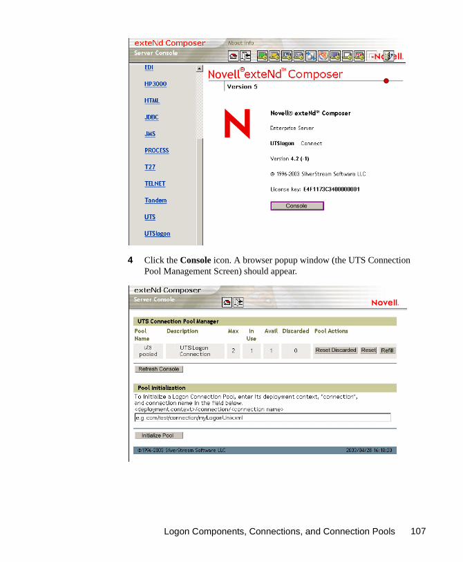
Logon Components, Connections, and Connection Pools 107
4 Click the Console icon. A browser popup window (the UTS Connection Pool Management Screen) should appear.

UTS Connect User’s Guide108
5 To initialize a Logon Connection Pool, enter its deployment context, the word "connection", and the actual connection name in the text field near the bottom of the screen. (See illustration above.) Then click the Initialize Pool button.
NOTE: Refer to the appropriate Composer Enterprise Server guide for more information.
6 Optionally click the Refresh Console button to update the view.
Connection Pool Management and Deployed ServicesThe Connection Pool Management Screen displays the current state of the connection(s) with the UTS Connect. The screen contains a table listing the Pool Name, Description of the connection, the maximum number of connections in the pool, the number of connections in use, the number of connections available, the number of connections discarded. It also contains several buttons allowing you to perform various actions related to connection pooling, which are outlined in the table below.
Table 1-2:
Button Name Action
Reset Discarded Resets the Discarded connections which are then reflected in the table
Reset (Pool) Resets the Available and Discarded connections which are then reflected in the table
Refill (Pool) Refills the pool with the maximum number of connections
Additional Buttons on UTS Connection Pool Manager Console
Refresh Console
Shows the current status of the connection pool
Initialize Pool Initializes a Logon Connection Pool by entering a relative path to the deployed lib directory. This will not work unless the deployed jar is extracted. Click on the SUBMIT button when finished.

Logon Components, Connections, and Connection Pools 109
Connection Discard Behavior
The performance benefits of connection pooling are based on the ability of more than one user to access a resource, or set of resources, at once. The way a connection is established begins with the logon component picking the User ID and Password from the table. If the connection fails, then it is discarded for this User ID and Password and tries another until a connection is established. The failure of one connection doesn’t necessarily prevent a successful connection from being established.
The Connect for UTS addresses the “one bad apple” problem by discarding any connection that can’t be established (for whatever reason: bad user ID, timed-out password, etc.) and reusing the others. When a connection is determined to be unusable, the Connect for UTS will write a message to the system log that says: “Logon connection in pool <Pool name> was discarded for User ID <User ID>.”
Screen Synchronization
Screen synchronization has special ramifications for users of pools. If a situation arises in which a user leaves a connection without the screen returning to its original state, the next user will begin a session with the screen in an unexpected state and an error will occur. To prevent this, there is a screen expression which the user can specify in the connection pool. It is important that the last action in a UTS Component be a Send Key action that will result in the session ending with the correct logon screen active.
NOTE: The last action should be an empty Check Screen action so that the UTS Terminal component waits until the launch screen arrives before giving up the connection. (This should happen automatically, when you create the Send Key action, but nevertheless, the last action should be the Check Screen.)
If you want to check, at runtime, for the presence of a bad screen at the end of a user session, include a Function Action at the end of your component’s action model that executes a function similar to the one shown below:
if((Screen.getText(1,11,5)== "Login" || Screen.getText(2,5,10) == "Data Entry" ) && (Screen.getTextFromRectangle(1,1,24,80).indexOf("COMMAND UNRECOGNIZED") == -1 || Screen.getTextFromRectangle(1,1,24,80).indexOf("UNSUPPORTED FUNCTION") == -1)) { java.lang.System.out.println("OK to exit"); }

UTS Connect User’s Guide110
// Otherwise, write error messages to Sys.out else { java.lang.System.out.println("Warning - Releasing logon connection at bad screen"); }
In this particular example, this function checks the screen text for either the “Login” header or the “Data Entry” field and also makes sure it doesn’t see the words “COMMAND UNRECOGNIZED” or “UNSUPPORTED FUNCTION.” If this is the case, it will write an error to the log.
111
A
Glossary
Glossary Appendix A
ANSI
American National Standards Institute.
Check Screen
An action that action signals the component that execution must not proceed until the screen is in a particular state, subject to a user-specified timeout value.
Connection Pooling
An arrangement whereby an intermediary process (whether the app server itself, or some memory-resident background process not associated with the server) maintains a set number of preestablished, pre-authenticated connections, and oversees the “sharing out” of these connections among client apps or end users.
Dumb Terminal
A computer terminal that has no onboard CPU, memory, or storage devices, beyond the minimum necessary to communicate with a more powerful host machine.
ECMAScript
Any JavaScript-like language that conforms to European Computer Manufacturers Association standard No. 262.
Native Environment Pane
A pane in the UTS Component Editor that provides an emulation of an actual UTS terminal session.
Screen Object
Represents the current UTS screen display
Send Key
An action that represents pressing a UTS-specific attention or function key.
UTS Connect User’s Guide112
Set Screen Text
An action that appears in the Action Model whenever there is map to the screen or keys entered on the screen.
UTS
A terminal originally developed by the Burroughs Corporation, later purchased by Unisys. Used to interact with mainframe computers including the ClearPath IX, 1100 and 2200.
Terminal Emulation
A program that allows a personal computer to act like a (particular brand of) terminal, e.g. a UTS. The computer thus appears as a terminal to the mainframe (host) computer and accepts the same escape sequences and other attention keys for functions such as cursor positioning and clearing the screen.
Unisys
Designers, manufacturers and marketers of computer-based information systems and related products and services. The UTS mainframe terminal was originally developed by Burroughs Corporation, which became part of Unisys in 1986. Mainframe computer models, including the A Series, V Series, and ClearPath™ NX run UTS terminal emulation

113
B
UTS Display Attributes
UTS Display Attributes Appendix B
The Screen.getAttribute() method will return one of the values shown below, representing the current attribute state of the onscreen character at the given location. The attributes listed below are just the most common and any combination of what is stated below could, theoretically occur. Basically, underlined, bold, blinking and reverse characters return a standard integer. This is then added to the hexadecimal number indicating whether the field is secure, protected, selected and/or vertical.
Number Attribute
0 standard (can type into - e.g., entry field)
16 (0X10) secure (can type into - e.g., passwords)
32 (0X20) protected (cannot type into)
33 (0X20)+1 protected and underlined
34 (0X20)+2 protected and bold
36 (0X20)+4 protected and blinking
40 (0X20)+8 protected and reverse
48 (0X10)+(0X20) secure and protected
64 (0X40) selected
80 (0X40) + (0X10) selected and secure
96 (0X20)+(0X40) selected and protected
98 (0X20)+(0X40)+2 selected, protected and bold
0X100 vertical

UTS Connect User’s Guide114
Viewing All Character Attributes at Once
Using the Screen.getAttribute() method, you can easily write a function that captures all attributes (at all screen locations) at once. The following custom script, for example, can be used at design time to display screen attributes in an alert dialog.
function showAttributes( myScreen )
{
var attribs = new String(); // create empty string
// Iterate over all rows and columns:
for (var i = 1; i <= myScreen.getRows(); i++, attribs += "\n" )
for (var k = 1; k <= myScreen.getCols(); k++)
attribs += " " + myScreen.getAttribute(i,k);
}
In your Action Model, you would include a function action with the following ECMAScript expression to call the script.:
alert(showAttributes( Screen ));
The following illustration shows a UTS screen:

UTS Display Attributes 115
The illustration below shows the result of applying the showAttributes() function to the screen (the illustration had to be cropped as the right/left margin would have gone outside the boundaries of the page):

UTS Connect User’s Guide116

117
C
Reserved Words
Reserved Words Appendix C
The following terms are reserved words in exteNd Composer for UTS Connect and should not be used as labels for any user-created variables, methods, or objects.
•USERID
•PASSWORD
•PROJECT
•Screen
•getAttribute
•getCols
•getCursorCol
•getCursorRow
•getNextMessage
•getPrompt
•getRows
•getStatusLine
•getText
•getTextFromRectangle
•hasMoreMessages
•putString
•putStringInField
•setMessageCaptureOff
•setMessageCaptureOn
•typeKeys

UTS Connect User’s Guide118

119
Index
AAction
Check Screen 36Action Model
examples 60, 61testing 66, 68
Action pane context menu 36Actions
deleting 65Send Key 34Set Screen Text 33, 36
Animationstarting 68step into 68toggle breakpoint 63
Animation Tools 68applications 18Architecture 15
connection pool 78
CCheck Screen Action 35
errors related to 73performance 104tips 72
Check Screen Actions 36Component Editor Window 28Components
executing 67selecting a Connection 28steps in creating 19, 25testing 66tips for building 72
Connecting 33and disconnecting 34
Connection Button 33Connection Discard Behavior 109Connection Pool
steps for creating 92Connection Pool Architecture 78Connection Pool Console, refreshing 108
Connection Poolsimplementing 83steps in creating 92
ConnectionPoolsstatus 108
Connection Resource 78, 92creating 20steps in creating 20
Connectionslogon 90maximum 108resetting discarded 108
constant-based 39constant-based parameters 22context menu items 34Control key down, dragging with 51Create Check Screen Button 34Creating a Connection Pool 92Creating a Logon Connection 95Creating a Logon Connection using a Pool
Connection 95Creating a Logon Connection using a Session
Connection 101CSU Id 22
Ddeleting an action 65Dragging and dropping to DOMs 56
EECMAScript 22, 75Entry Wait, pools 97errors 73
connection 108Executing a component 67expression-based parameters 22
FFloating Keypad 30

120
GgetTextFromRectangle() 51
HHost App Name 22Host Connection ID 22, 98
IInactivity Lifetime
pools 97session connection 103
Initialize Pool 108
KKEEPALIVE 86Keep Alive 102
session connection 102KeepAlive
pools 97KEEPALIVE Actions
recording 95KeepAlive Actions 83Keyboard 30keypad 30
Llaunch screen 84Logoff action 84LOGOFF Actions
recording 95Logon action 84LOGON Actions
recording 95Logon Actions 85Logon Component
definition 83Logon Components
creating 93Logon Connections 20, 78
session connections 101
MManaging Pools 104Maximizing Performance with KEEP ALIVE
Actions 88Maximizing Performance with the Logon
Component 85MultiBridge Connection 20
NNative Environment Pane 28newlines, in rectangular screen selections 51
OOverride the UID/PWD 91
Pparameters, constant vs expression-based 22Password 22
Set Screen Text automatically 35Performance 75, 77, 104
logon connection and pools 100Pool Info dialog 96pools 96
checking status 108implementing 83initializing 108managing 104maximum connections 108refilling 108resetting 108
Pool Size 97
RRecord Button 33Recording 33, 53
adding to a previous recording 61and animating 68editing after recording 61start/stop 34turning off 60

121
rectangular onscreen selections 51Redundant Data, dealing with 70Refill Pool 108Refresh Consolel 108Reset Discarded 108Reset Pool 108row/column placement 57
Sscreen, T27 terminal 31Screen Object, definition of 31Screen Synchronization 109Screen Wait time 22, 57, 72Send Key Action
tips 72Send Key Button 34Session Connections 101Session Name 22Set Screen Text 35Set Screen Text Action 35, 36
errors related to 74tips 72
Set Screen Text Button 33shift-drag selection technique 51Single Sign-On and connection pools 91Start Animation 68Static versus Dynamically Created
Documents/Elements 101status line, in Native Environment Pane 47status line, marking row/column placement 57Step Into 68
TT27, definition of 17T27 Connection types 78T27 terminal screen 31Temp XML Document 27Terminal Keypad 30Toggle Breakpoint 63toolbar
connection 33Create Check Screen Button
ActionsCreate Check Screen 34
record 33Send Key button 34Set Screen Text 33
toolbar buttons 32
UUnisys mainframes 17Userid
Set Screen Text automatically 35USERID/PASSWORD 98Userids 22
Vvariables, Userid and Password 22

122