nov i e storag m aq recharg z/mo ber c wit par m
TRANSCRIPT

Vol.:(0123456789)
1 3
Novel Insights into Energy Storage Mechanism of Aqueous Rechargeable Zn/MnO2 Batteries with Participation of Mn2+
Yongfeng Huang1,2, Jian Mou1, Wenbao Liu1,2, Xianli Wang1, Liubing Dong1 *, Feiyu Kang1,2 *, Chengjun Xu1 *
Yongfeng Huang and Jian Mou have contributed equally to this work.
* Liubing Dong, [email protected]; Feiyu Kang, [email protected]; Chengjun Xu, [email protected] Shenzhen Geim Graphene Center, Graduate School at Shenzhen, Tsinghua University, Shenzhen 518055,
People’s Republic of China2 State Key Laboratory of New Ceramics and Fine Processing, School of Materials Science and Engineering,
Tsinghua University, Beijing 100084, People’s Republic of China
HIGHLIGHTS
• Pourbaix diagram of Mn–Zn–H2O system was used to analyze the charge–discharge processes of Zn/MnO2 batteries.
• Electrochemical reactions with the participation of various ions inside Zn/MnO2 batteries were revealed.
• A detailed explanation of phase evolution inside Zn/MnO2 batteries was provided.
ABSTRACT Aqueous rechargeable Zn/MnO2 zinc-ion batteries (ZIBs) are reviving recently due to their low cost, non-toxicity, and natural abundance. However, their energy storage mechanism remains controversial due to their complicated electrochemical reactions. Meanwhile, to achieve satisfactory cyclic stability and rate performance of the Zn/MnO2 ZIBs, Mn2+ is introduced in the electrolyte (e.g., ZnSO4 solution), which leads to more complicated reactions inside the ZIBs systems. Herein, based on comprehensive analysis methods including electrochemical analysis and Pourbaix diagram, we provide novel insights into the energy storage mechanism of Zn/MnO2 batteries in the presence of Mn2+. A complex series of electrochemical reactions with the co-participation of Zn2+, H+, Mn2+, SO4
2−, and OH− were revealed. During the first discharge process, co-insertion of Zn2+ and H+ promotes the transformation of MnO2 into ZnxMnO4, MnOOH, and Mn2O3, accompanying with increased electrolyte pH and the formation of ZnSO4·3Zn(OH)2·5H2O. During the subsequent charge process, ZnxMnO4, MnOOH, and Mn2O3 revert to α-MnO2 with the extraction of Zn2+ and H+, while ZnSO4·3Zn(OH)2·5H2O reacts with Mn2+ to form ZnMn3O7·3H2O. In the following charge/discharge processes, besides aforementioned electrochemical reactions, Zn2+ reversibly insert into/extract from α-MnO2, ZnxMnO4, and ZnMn3O7·3H2O hosts; ZnSO4·3Zn(OH)2·5H2O, Zn2Mn3O8, and ZnMn2O4 convert mutually with the participation of Mn2+. This work is believed to provide theoretical guidance for further research on high-performance ZIBs.
KEYWORDS Zinc-ion battery; MnO2 cathode; Energy storage mechanism; Phase evolution
ISSN 2311-6706e-ISSN 2150-5551
CN 31-2103/TB
ARTICLE
Cite asNano-Micro Lett. (2019) 11:49
Received: 15 April 2019 Accepted: 14 May 2019 Published online: 6 June 2019 © The Author(s) 2019
https://doi.org/10.1007/s40820-019-0278-9
Nano-Micro Lett. (2019) 11:4949 Page 2 of 13
https://doi.org/10.1007/s40820-019-0278-9© The authors
1 Introduction
Lithium-ion batteries (LIBs) have been widely used in consumer electronics due to high energy density, portabil-ity, and some other merits [1–4], whereas their security concerns and high cost restrict their large-scale applica-tions in stationary grid storage and electric vehicles [5, 6]. Therefore, much attention has been paid to seek safe, eco-friendly, low-cost, and high-performance battery systems [6, 7]. Aqueous rechargeable zinc-ion batter-ies (ZIBs) are developed as a battery system, in which low-cost, non-toxic, and naturally abundant zinc metal is used as an anode and environment-friendly neutral aque-ous Zn2+-containing solution serves as electrolyte [8]. In recent years, a series of high-performance cathode materi-als for ZIBs have also been studied such as Prussian blue analog [9–11], vanadium oxides [12–19], manganese oxides [20–28], and some metal sulfides [29–31]. Among these materials, MnO2 is particularly concerned for its high theoretical specific capacity, low cost, eco-friend-liness, and diverse crystallographic polymorphs (e.g., α-MnO2, δ-MnO2, and γ-MnO2) [27, 28, 32].
Many efforts have been made to reveal the energy stor-age mechanisms of Zn/MnO2 ZIBs. Up to now, three types of energy storage mechanisms were proposed, including (i) Zn2+ insertion/extraction into/from MnO2 [8, 33–36], (ii) conversion between MnO2 and MnOOH with the participa-tion of H+ [37], and (iii) co-insertion of H+ and Zn2+ [38]. Mechanisms (i) and (ii) explain the formation of ZnMn2O4 and MnOOH as discharging products on MnO2 cathode in ZIBs, respectively, while cannot explain that there are two redox processes during one charge/discharge cycle of ZIBs. Mechanism (iii) seems to be capable of explaining the coex-istence of ZnMn2O4 and MnOOH as discharging products on MnO2 cathode, but deeper analysis will find that it is not accurate: The mechanism deems that potential of Zn2+ insertion is lower than that of H+ insertion (this means that MnOOH forms before ZnMn2O4 once the battery discharge process begins), being conflicted to the experimental result that MnOOH appears latter than ZnMn2O4. In short, the current mechanisms are unsatisfactory to explain genuine charge/discharge process in ZIBs, mainly because they were proposed based on a simplistic view that the insertion of Zn2+ and H+ and the phase change from MnO2 to ZnMn2O4 or MnOOH are highly reversible. Furthermore, to achieve
satisfactory cyclic stability and rate performance of the Zn/MnO2 ZIBs, Mn2+ ions are always introduced in the elec-trolyte [37]. However, electrochemical reactions inside the ZIBs become more complicated in such cases, thus corre-sponding energy storage mechanism has not been clearly revealed. Therefore, it is necessary to re-examine the ther-modynamic and kinetic characteristics of Zn/MnO2 ZIBs to propose a reasonable Zn2+ storage mechanism.
In fact, for the active materials in aqueous ZIBs and some other rechargeable aqueous batteries, their structure and phase generally undergo complex changes during charge/dis-charge processes (e.g., the active materials can interact with not only metal ions, but also H+, OH−, and water molecules) [39]. This is an important reason why the energy storage mechanism of MnO2 cathode in ZIBs is still inconclusive [40–43]. Besides general experimental techniques such as cyclic voltammetry (CV) and galvanostatic charge–discharge (GCD) tests, Pourbaix diagram (E-pH diagram) has been widely used to study electrochemical reactions in aqueous solution [44–47]. The electrochemical reductive products of active materials can be predicted according to the thermody-namics, which is beneficial for us to understand the charge/discharge process. Therefore, we combined experimental methods with the E-pH diagram of the Mn–Zn–H2O system together to comprehensively analyze the charge/discharge processes of MnO2 cathode in ZIBs and tried to reveal the authentic energy storage mechanism.
Herein, based on comprehensive analysis methods includ-ing electrochemical analysis and E-pH diagram, etc., we pro-vide novel insights into the energy storage mechanism of Zn/MnO2 batteries with the co-participation of Zn2+, H+, Mn2+, SO4
2−, and OH−. During the first discharge process, co-insertion of Zn2+ and H+ promotes the transformation of MnO2 into ZnxMnO4, MnOOH, and Mn2O3, accompa-nying with increased electrolyte pH and the formation of ZnSO4·3Zn(OH)2·5H2O (noted as “BZSP”). During the subsequent charge process, ZnxMnO4, MnOOH, and Mn2O3 revert to α-MnO2 with the extraction of Zn2+ and H+, while BZSP reacts with Mn2+ to form ZnMn3O7·3H2O. In the following charge/discharge processes, besides aforemen-tioned electrochemical reactions, Zn2+ reversibly inserts into/extract from α-MnO2, ZnxMnO4, and ZnMn3O7·3H2O hosts, and BZSP, Zn2Mn3O8, and ZnMn2O4 convert mutu-ally with the participation of Mn2+. This work is believed to provide theoretical guidance for further research on high-performance ZIBs.
Nano-Micro Lett. (2019) 11:49 Page 3 of 13 49
1 3
2 Experimental
2.1 Material Synthesis
MnO2 cathode material was synthesized through a chemi-cal co-precipitation method. One hundred and fifty mil-liliters of 0.1 M MnSO4 aqueous solution was dropped into 100 mL of KMnO4 (0.1 M) solution under magnetic stirring, followed by continuous stirring for 6 h at room temperature. The resulting precipitate was filtered, washed repeatedly with deionized water, and dried at 80 °C for 12 h. The obtained sample was thoroughly ground in an agate mortar and then annealed at 400 °C for 5 h in air atmosphere. Note that we applied the heat treatment to improve the crystalline of MnO2 because this makes it easier for us to use X-ray diffraction (XRD) and transmis-sion electron microscopy (TEM) to detect the phase evolu-tion of MnO2 cathode during charge/discharge processes.
2.2 Electrochemical Characterizations
The cathode was prepared by coating a mixture paste of 70 wt% of MnO2 powder, 20 wt% of acetylene black, and 10 wt% of LA133 binder on a stainless steel foil and dried overnight under vacuum conditions at 80 °C. In the prepared cathode, the mass loading of MnO2 is around 1 mg cm−2. Zn/MnO2 ZIBs were assembled based on MnO2 cathode, metallic Zn foil anode, air-laid paper sepa-rator, and zinc salt solution electrolyte (2 M ZnSO4 or 2 M ZnSO4 +0.5 M MnSO4 solution).
The assembled ZIBs were kept more than 4 h before electrochemical measurements. The CV and GCD tests were performed on a Bio-logic VMP3 multichannel elec-trochemical station and a Land CT2001 battery tester, respectively. CV tests of the prepared MnO2 cathode were also carried out in a three-electrode system, in which a platinum plate as the counter electrode, a saturated calo-mel electrode (SCE) as the reference electrode, and 50 mL electrolyte was applied.
2.3 Material Characterizations
Microstructure and composition were characterized by XRD (Rigaku 2500) with Cu-Kα radiation operating
at 40 kV and 100 mA within an angle range of 10° to 70° at a scan speed of 5° min−1. Micro-morphology was observed by field emission scanning electron microscopy (SEM, Zeiss Supra 55) and TEM (Tecnai G2 F30). Ele-ment content in electrodes and electrolytes was analyzed by inductively coupled plasma atomic emission spectrom-etry (ICP-AES).
3 Results and Discussion
3.1 Characterization of MnO2
The MnO2 material used in this work was synthesized through a chemical co-precipitation method. XRD pattern and micro-morphology observations in Fig. 1a–c show that the synthesized MnO2 powder is crystalline α-MnO2 nanorod with a diameter of 10–60 nm and length of several hundred nanometers. From the XRD pattern in Fig. 1a, it seems that the strongest peak is the one at ~ 12.8°, but if the background is taken into account, the strongest peak is still the one at ~ 37.5°, which matches well with the α-MnO2 (PDF# 44-0141). In addition, since the as-prepared sample is nanobelts, (110) plane (corresponding to the diffraction peak at ~ 12.8°) is considered as preferred orientation, thus leading to high diffraction intensity. A similar phenomenon was also observed for some other MnO2 nanomaterials [38]. From the high-resolution TEM (HRTEM) image in Fig. 1d, the crystal planes (121) and (330) of the α-MnO2 with a corresponding interplanar spacing of 0.238 nm and 0.233 nm respectively are observed, and high crystallinity of the as-synthesized α-MnO2 sample is also confirmed.
3.2 Electrochemical Analysis
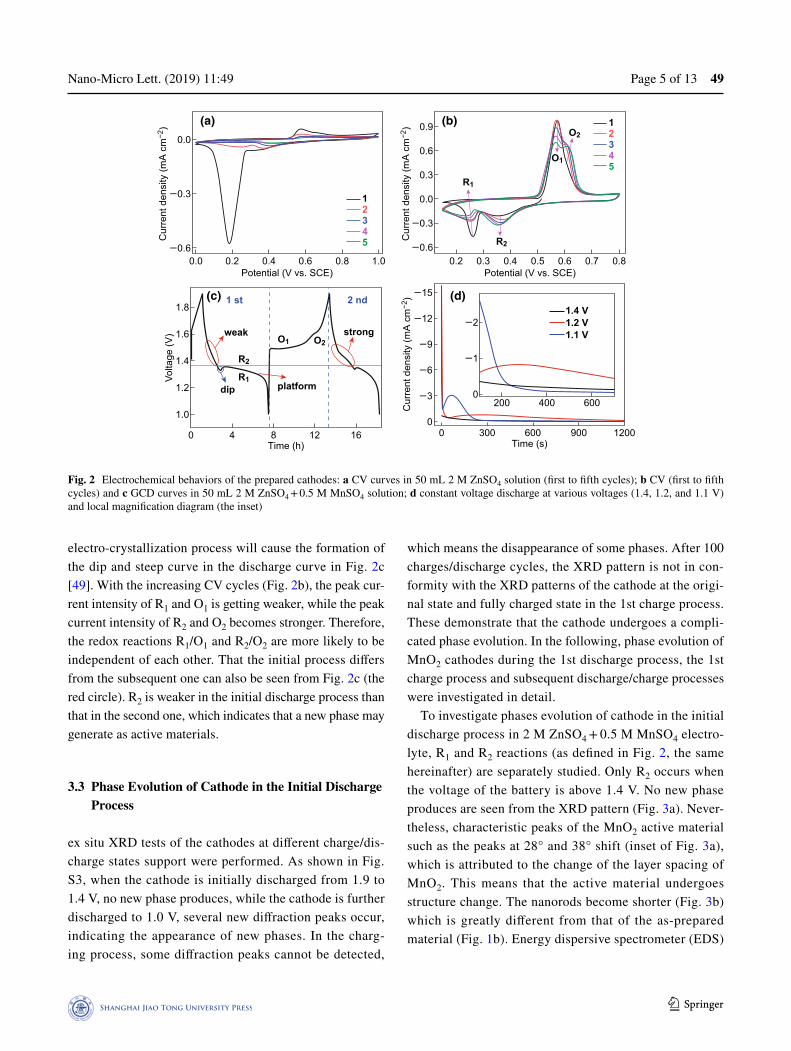
We first studied the electrochemical behaviors of MnO2 cathode in two different electrolytes, including 50 mL 2 M ZnSO4 (Fig. 2a) and 50 mL 2 M ZnSO4 + 0.5 M MnSO4 mixture solution (Fig. 2b–d). The capacity and rate perfor-mance of the MnO2 cathode in ZnSO4 + MnSO4 electrolyte are exhibited in Fig. S1. Note that MnO2 cathode would dissolve in ZnSO4 electrolyte during charge/discharge pro-cesses, as detected by ICP-AES tests in Table S1. (This has also been pointed out in previous researches.) [37] With the addition of Mn2+ in the electrolyte, the redox peaks in CV curves (except for the 1st CV cycle) in Fig. 2a, b become

Nano-Micro Lett. (2019) 11:4949 Page 4 of 13
https://doi.org/10.1007/s40820-019-0278-9© The authors
more obvious, and meanwhile, the gap between oxidation peak and reduction peak becomes smaller, which indicates that the reversibility of electrochemical process gets bet-ter. In Fig. 2a, the reduction peak is much stronger than the oxidation peak in the first cycle, which means that discharge products cannot be electrochemically oxidized completely. By contrast, the intensity of the reduction peak is close to that of the oxidation peak in Fig. 2b. Above phenomenon suggests that Mn2+ concentration in electrolyte plays a cru-cial role in the first discharge/charge process [48]. There are two pairs of redox peaks when the electrode discharges/charges in the 2 M ZnSO4 + 0.5 M MnSO4 electrolyte (Fig. 2b). The reduction peaks at low and high potentials are denoted as R1 and R2, respectively, and the oxidation peaks at low and high potentials are denoted as O1 and O2, respectively. Considering that electro-deposition of Mn2+ will occur only when the cathode potential reaches about
0.8 V versus SCE at the constant current of 0.1 A cm−2 (Fig. S2), the oxidation reactions of O1 and O2 ranging from 0.5 to 0.65 V versus SCE (Fig. 2b) are not caused by the electro-deposition of Mn2+. This confirms that the preclusion of MnO2 dissolution by Mn2+ in the electrolyte should be the dominant reason for good reversibility of discharge/charge processes in 2 M ZnSO4 + 0.5 M MnSO4 electrolyte.
There is a dip and a platform in the initial GCD curve (Fig. 2c) and the reaction type of R1 (at about 1.2 V) and R2 (at about 1.4 V) are further studied by the constant volt-age discharge test (Fig. 2d). The current changes greatly when the battery is discharged at 1.2 V at which R1 will happen, and it keeps almost flat when discharged at 1.4 V at which R2 will occur. This indicates that a heterogene-ous reaction occurs during R1 and a homogeneous reaction occurs during R2. Such a heterogeneous reaction between solid phases accompanying with nucleation process and
202 Theta (degree)
α-MnO2 (PDF# 44-0141)
(a) (b)
(d)
d=0.672 nm
d=0.238 nm
d=0.233 nm
(121)
(330)
(c)
100 nm
10 nm 5 nm
40
Inte
nsity
60 80
Fig. 1 a XRD pattern, b SEM image, c STEM, and d HRSTEM images of the synthesized MnO2 nanorods
Nano-Micro Lett. (2019) 11:49 Page 5 of 13 49
1 3
electro-crystallization process will cause the formation of the dip and steep curve in the discharge curve in Fig. 2c [49]. With the increasing CV cycles (Fig. 2b), the peak cur-rent intensity of R1 and O1 is getting weaker, while the peak current intensity of R2 and O2 becomes stronger. Therefore, the redox reactions R1/O1 and R2/O2 are more likely to be independent of each other. That the initial process differs from the subsequent one can also be seen from Fig. 2c (the red circle). R2 is weaker in the initial discharge process than that in the second one, which indicates that a new phase may generate as active materials.
3.3 Phase Evolution of Cathode in the Initial Discharge Process
ex situ XRD tests of the cathodes at different charge/dis-charge states support were performed. As shown in Fig. S3, when the cathode is initially discharged from 1.9 to 1.4 V, no new phase produces, while the cathode is further discharged to 1.0 V, several new diffraction peaks occur, indicating the appearance of new phases. In the charg-ing process, some diffraction peaks cannot be detected,
which means the disappearance of some phases. After 100 charges/discharge cycles, the XRD pattern is not in con-formity with the XRD patterns of the cathode at the origi-nal state and fully charged state in the 1st charge process. These demonstrate that the cathode undergoes a compli-cated phase evolution. In the following, phase evolution of MnO2 cathodes during the 1st discharge process, the 1st charge process and subsequent discharge/charge processes were investigated in detail.
To investigate phases evolution of cathode in the initial discharge process in 2 M ZnSO4 + 0.5 M MnSO4 electro-lyte, R1 and R2 reactions (as defined in Fig. 2, the same hereinafter) are separately studied. Only R2 occurs when the voltage of the battery is above 1.4 V. No new phase produces are seen from the XRD pattern (Fig. 3a). Never-theless, characteristic peaks of the MnO2 active material such as the peaks at 28° and 38° shift (inset of Fig. 3a), which is attributed to the change of the layer spacing of MnO2. This means that the active material undergoes structure change. The nanorods become shorter (Fig. 3b) which is greatly different from that of the as-prepared material (Fig. 1b). Energy dispersive spectrometer (EDS)
12345
12345
0.0
−0.3
−0.6
0.9
0.6
0.3
0.0
−0.3
−0.6
−15
−12
−9
−6
−3
0
−2
−1
0
1.8
1.6
1.4
1.2
1.0
Cur
rent
den
sity
(mA
cm
−2)
Cur
rent
den
sity
(mA
cm
−2)
Cur
rent
den
sity
(mA
cm
−2)(a)
(d)(c)
(b)
0.0 0.2 0.4 0.6Potential (V vs. SCE)
6.03.02.08.0 0.5
R2
R1
O1
O2
O2O1
R1
R2
dip
weak
platform
strong
2 nd1 st
0.4 0.7Potential (V vs. SCE)
0.81.0
0 4 8 12 16 0Time (s)
300
200 400 600
1.4 V1.2 V1.1 V
600 900 1200Time (h)
Volta
ge (V
)
Fig. 2 Electrochemical behaviors of the prepared cathodes: a CV curves in 50 mL 2 M ZnSO4 solution (first to fifth cycles); b CV (first to fifth cycles) and c GCD curves in 50 mL 2 M ZnSO4 + 0.5 M MnSO4 solution; d constant voltage discharge at various voltages (1.4, 1.2, and 1.1 V) and local magnification diagram (the inset)

Nano-Micro Lett. (2019) 11:4949 Page 6 of 13
https://doi.org/10.1007/s40820-019-0278-9© The authors
analysis in Fig. S4 suggests that the molar ratio of Zn, Mn, and S is approximately 1:16:0. To exclude the influence of electrolyte’s absorption, we immersed the electrodes in 2 M ZnSO4 for 48 h and washed several times with deionized water. Neither Zn nor S element is found in the SEM–EDS result (Fig. S5). Thus, the existence of Zn in the cathode when discharging to 1.4 V is caused by the insertion of zinc ions in MnO2, instead of zinc ion adsorp-tion on the cathode surface. In other words, zinc ion inser-tion happens when the voltage of the Zn/MnO2 battery is above 1.4 V. The process of zinc-ion insertion in MnO2 can be written as:
R1 reaction is then studied. When the battery is discharged to 1.2 V and then to the 1 V at constant current several new phases (XRD patterns in Fig. 3c) appear, which are confirmed as BZSP (PDF#39-0688), α-MnOOH (PDF#24-0713), and α-Mn2O3 (PDF#44-1442). There are many large hexagonal nanosheets in the SEM image (Fig. 3d). The Zn, O, and S element distribute evenly over the whole hexagonal nanosheets (Fig. S6b, c, e, f). And the atomic proportion of Zn to S is about 4:1 from the SEM–EDS results (Fig. S6d). Combined with the XRD result, we conclude that the
(1)MnO2+ xZn
2+ + 2xe−→ Zn
xMnO
2
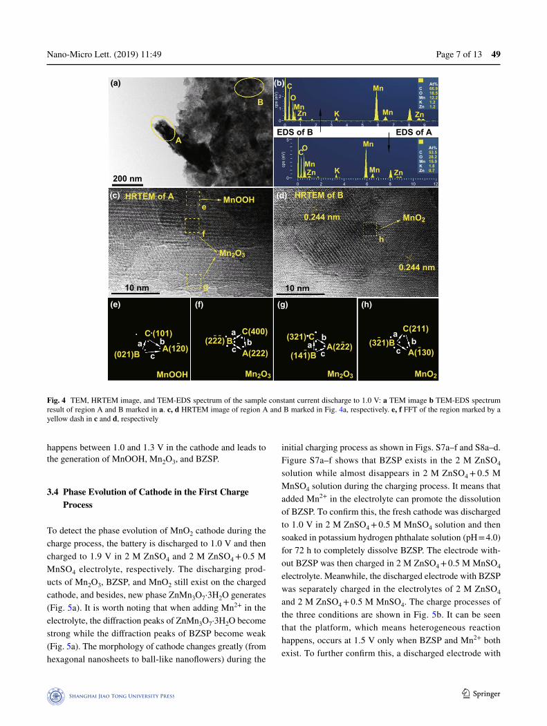
hexagonal nanosheets are BZSP. The structure evolution of cathode in the first discharge is shown in Fig. 3e. The exist-ence of α-MnOOH and α-Mn2O3 is further demonstrated by HRTEM (Fig. 4). The α-Mn2O3 is semi-coherent with the α-MnOOH phase (Fig. 4c). These substances and their reactions can be written as [21, 28, 37]:
Phases in regions e, f, g, and h in Fig. 4c, d marked by yellow dash can be identified as α-MnOOH, α-Mn2O3, α-Mn2O3, and α-ZnxMnO2, respectively, through fast Fourier trans-form (FFT) in Fig. 4e–h (detailed calculation procedures are given in Table S2–S4). From the TEM-EDS result, the Zn element can be found in both regions A and B and there is no S element in these regions (Fig. 4b), further confirming that zinc-ion inserts into the nanorods. Besides, the genera-tion of BZSP and α-MnOOH indicates that H+ and Zn2+ participate in the reaction. From the above discussions, zinc ion insertion in α-MnO2 occurs around 1.4 V versus Zn2+/Zn to generate α-ZnxMnO2, and proton conversion reaction
(2)4Zn
2+ + SO2−
4+ 5H
2O + 6OH
−→ ZnSO
4⋅ 3Zn(OH)
2⋅ 5H
2O
(3)MnO2+ H
+ + e−→ MnOOH
(4)2MnO2+ 2H
+ + 2e−→ Mn
2O
3+ H
2O
2838
1.4 V
Origin
1.4 V
10 20 30 40 50 602 Theta (degree)
10 20 30 40 50 60 702 Theta (degree)
♣ Steal
♣ Stainless steel
a-MnO2 (PDF #44-0141)
MnOOH (PDF #24-0713)
Mn2O3 (PDF #44-1442)
3Zn(OH)2·ZnSO4·5H2O(PDF #39-0688)
ZnSO4·3Zn(OH)2·5H2O
Origin
(a)
(c)
(b)(e) S
Mn
O
Zn
ZnxMn2O4
Mn2O3
MnOOH
MnO2
ZnSO4
1.2 V
1.4 V
Zn2+ (in
serti
on)
1.2 VH + (insertion)
H
100 nm
(d)
BZSP
30 35
♣
10 µm
♣
H+
(convertion)
OH−
Fig. 3 The results of the cathode which is constant current discharged to 1.4 V and then constant voltage discharged at 1.4 V in 2 M ZnSO4 + 0.5 M MnSO4 electrolyte for 2 h: a XRD pattern and locally enlarged image (the inset); b SEM image of the surface of the cathode. Another cathode which is constant current discharged to 1.0 V: c XRD pattern; d SEM image of the surface of the cathode; e phase evolution of cathode during the first discharge process
Nano-Micro Lett. (2019) 11:49 Page 7 of 13 49
1 3
happens between 1.0 and 1.3 V in the cathode and leads to the generation of MnOOH, Mn2O3, and BZSP.
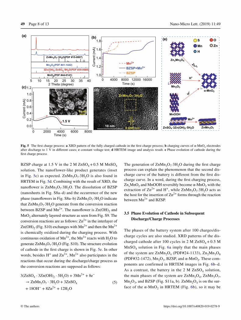
3.4 Phase Evolution of Cathode in the First Charge Process
To detect the phase evolution of MnO2 cathode during the charge process, the battery is discharged to 1.0 V and then charged to 1.9 V in 2 M ZnSO4 and 2 M ZnSO4 + 0.5 M MnSO4 electrolyte, respectively. The discharging prod-ucts of Mn2O3, BZSP, and MnO2 still exist on the charged cathode, and besides, new phase ZnMn3O7·3H2O generates (Fig. 5a). It is worth noting that when adding Mn2+ in the electrolyte, the diffraction peaks of ZnMn3O7·3H2O become strong while the diffraction peaks of BZSP become weak (Fig. 5a). The morphology of cathode changes greatly (from hexagonal nanosheets to ball-like nanoflowers) during the
initial charging process as shown in Figs. S7a–f and S8a–d. Figure S7a–f shows that BZSP exists in the 2 M ZnSO4 solution while almost disappears in 2 M ZnSO4 + 0.5 M MnSO4 solution during the charging process. It means that added Mn2+ in the electrolyte can promote the dissolution of BZSP. To confirm this, the fresh cathode was discharged to 1.0 V in 2 M ZnSO4 + 0.5 M MnSO4 solution and then soaked in potassium hydrogen phthalate solution (pH = 4.0) for 72 h to completely dissolve BZSP. The electrode with-out BZSP was then charged in 2 M ZnSO4 + 0.5 M MnSO4 electrolyte. Meanwhile, the discharged electrode with BZSP was separately charged in the electrolytes of 2 M ZnSO4 and 2 M ZnSO4 + 0.5 M MnSO4. The charge processes of the three conditions are shown in Fig. 5b. It can be seen that the platform, which means heterogeneous reaction happens, occurs at 1.5 V only when BZSP and Mn2+ both exist. To further confirm this, a discharged electrode with
(a) (b) C
CO
Mn
Mn
Mn ZnZn K
OMnZn K
Mn
Mn Zn
200 nm
10 nm 10 nm
A
(d)(c)
(e) (f) (g) (h)
h
HRTEM of Ae
g
C (101)
MnOOH
BC(400) (321) C
A(222)A(222)
(141)B(321)B
A(130)
C(211)
Mn2O3 Mn2O3 MnO2
MnO2
0.244 nm
0.244 nm
HRTEM of B
(021)B A(120)(222)
f
MnOOH
Mn2O3
B
COMnKZn
At%66.918.512.21.21.2
COMnKZn
At%53.528.215.91.80.7
cps
(eV
)
cps
(eV
)
2
1
0
5
0
0
0 2 4 6 8 10 12
1 2 3 4 5 6 7 8 9
EDS of B EDS of A
ca b b b b
c c c
aa
a
Fig. 4 TEM, HRTEM image, and TEM-EDS spectrum of the sample constant current discharge to 1.0 V: a TEM image b TEM-EDS spectrum result of region A and B marked in a. c, d HRTEM image of region A and B marked in Fig. 4a, respectively. e, f FFT of the region marked by a yellow dash in c and d, respectively
Nano-Micro Lett. (2019) 11:4949 Page 8 of 13
https://doi.org/10.1007/s40820-019-0278-9© The authors
BZSP charge at 1.5 V in the 2 M ZnSO4 + 0.5 M MnSO4 solution. The nanoflower-like product generates (inset in Fig. 5c) as expected. ZnMn3O7·3H2O is also found in HRTEM in Fig. 5d. Combining with the result of XRD, the nanoflower is ZnMn3O7·3H2O. The dissolution of BZSP (nanosheets in Fig. S8a–d) and the occurrence of the new phase (nanoflowers in Fig. S8a–b) ZnMn3O7·3H2O indicate that ZnMn3O7·3H2O generate from the conversion reaction between BZSP and Mn2+. The nanoflower is Zn(OH)2 and MnO2 alternately layered structure as seen from Fig. S9. The conversion reactions are as follows: Zn2+ in the interlayer of Zn(OH)2 (Fig. S10) exchanges with Mn2+ and then the Mn2+ is chemically oxidized during the charging process. With continuous oxidation of Mn2+, the Mn2+ reacts with H2O to generate ZnMn3O7·3H2O (Fig. S10). The structure evolution of cathode in the first charge is shown in Fig. 5e. In other words, besides H+ and Zn2+, Mn2+ also participates in the reactions that occur during the discharge/charge process as the conversion reactions are supposed as follows:
(5)3(ZnSO
4⋅ 3Zn(OH)
2⋅ 5H
2O) + 3Mn
2+ + 8e−
→ ZnMn3O
7⋅ 3H
2O + 3ZnSO
4
+ 18OH− + 8Zn
2+ + 12H2O
The generation of ZnMn3O7·3H2O during the first charge process can explain the phenomenon that the second dis-charge curve of the battery is different from the first dis-charge curve. In a word, during the first charging process, ZnxMnO2 and MnOOH reversibly become α-MnO2 with the extraction of Zn2+ and H+, while ZnMn3O7·3H2O acts as the host for the insertion of Zn2+ forms through the reaction between Mn2+ and BZSP.
3.5 Phase Evolution of Cathode in Subsequent Discharge/Charge Processes
The phases of the battery system after 100 charges/dis-charge cycles are also studied. XRD patterns of the dis-charged cathode after 100 cycles in 2 M ZnSO4 + 0.5 M MnSO4 solution in Fig. 6a imply that the main phases of the system are ZnMn2O4 (PDF#24-1133), Zn2Mn3O8 (PDF#32-1472), Mn2O3, BZSP, and α-MnO2. These com-ponents are confirmed in HRTEM images in Fig. 6b–d. As a contrast, the battery in the 2 M ZnSO4 solution, the main phases of the system are ZnMn2O4, ZnMn3O7, Mn2O3, and BZSP (Fig. S11a, b). ZnMn2O4 is on the sur-face of the α-MnO2 in HRTEM (Fig. 6b), so it may be
ZnMn3O7·3H2O(PDF #15-0807)
ZnSO4·3Zn(OH)2·5H2O
MnO2(PDF #44-0141)
Mn2O3(PDF #41-1442) Mn2+
BZSP+Mn2+
BZSP3Zn(OH)2·ZnSO4·5H2O(PDF #39-0688)
5
Cur
rent
(mA
)
Cur
rent
(mA
)
10
1.5 V
0 2000 4000 6000 8000Time (s)
(c)
(b)(a)(e)
1 µm
0.695 nm
ZnMn3O7·3H2O
10 nm
(d)1.2
1.0
0.8
0.6
0.4
0.2
0.0
15 20 30 35 40 0 4000
1.8
1.6
1.4
1.2
1.08000 12000 16000
S
ZnxMn2O4
Mn2O3
ZnMn3O7
α-MnO2
MnOOH
H+
Mn2+
H+
Zn 2+
MnH
OZn
Time (s)2 Theta (degree)25
Fig. 5 The first charge process: a XRD pattern of the fully charged cathode in the first charge process; b charging curves of α-MnO2 electrodes after discharge to 1 V in different cases; c constant voltage test; d HRTEM image and analysis result. e Phase evolution of cathode during the first charge process

Nano-Micro Lett. (2019) 11:49 Page 9 of 13 49
1 3
converted from α-MnO2. Zn2Mn3O8 and ZnMn2O4 are coherent in the HRTEM (Fig. 6c, d). Thus, Zn2Mn3O8 reacts with Mn2+ to form ZnMn2O4. (This will be fur-ther analyzed in the Mn–Zn–O diagram in the follow-ing part.) There are two kinds of nanoparticles after 100 cycles (Fig. S12), which may be converted from BZSP and Mn2+ as nanosheets and nanoparticles surround each other. Combining the XRD result (Fig. 6a), the phase is Zn2Mn3O8. Thus, Zn2Mn3O8 is generated from the reac-tions between BZSP and Mn2+. The structure evolution of cathode after 100 cycles is shown in Fig. 6e. Reactions between them are as follows:
To sum up, within the continuous charge/discharge process, ZnMn2O4 and Zn2Mn3O8 as host for insertion of Zn2+ fur-ther generate on the surface of MnO2, which implies that the phase change of MnO2 cathode is irreversible.
3.6 Thermodynamic Analysis
When dynamic conditions are met, the phases can be pre-dicted from Zn-Mn–O diagram since the system of the Zn/ZnSO4 + MnSO4/MnO2 battery reaches an equilibrium state
(6)Zn
xMnO
2+ (0.5 − x)Zn2+ + (1 − 2x)e− → 0.5ZnMn
2O
4
(7)Zn2Mn
3O
8+Mn
2+→ 2ZnMn
2O
4
after a certain cycle. The isothermal cross section of the phase diagram (25 °C) is shown in Fig. 7a. Since MnO2 is used as an active material and ZnSO4 + MnSO4 as the electrolyte for the beginning, the phase of the reaction is bound to three elements (Mn, O, and Zn). When the thermodynamic stability of the system reaches, the definite phases include manganese oxide (MnO2, Mn2O3, Mn3O4, and MnO) and zinc manganese oxide (ZnMn2O4 and Zn2Mn3O8) (Fig. 7a). Detailed density func-tional theory calculation and theoretical analysis of MnO2 as a cathode of ZIBs are given in Discussion S1 and S2 in Sup-porting Information). There are two paths to the reduction of MnO2: (i) MnO2 → Mn2O3 → Mn3O4 → MnO, in which path there is no Zn involvement; (ii) MnO2 → ZnMn2O4 with Zn involvement. For Mn2O3 oxidation, it is directly oxidized to MnO2: Mn2O3 → MnO2. The oxidation of ZnMn2O4 has two paths: Zn extracts out completely from ZnMn2O4 to generate MnO2 or Mn partially removes from ZnMn2O4 to generate Zn2Mn3O8. They can express as: (1) ZnMn2O4 → MnO2; (2) ZnMn2O4 → Zn2Mn3O8. And there’s only one way for the Zn2Mn3O8 reduction: Zn2Mn3O8 → ZnMn2O4. In the Zn/ZnSO4 + MnSO4/α-MnO2 system studied in this paper, MnO dissolves in the electrolyte or can be inhibited when there is a certain concentration of Mn2+. Thus, there are five kinds of phases that may exist, such as MnO2, Mn2O3, Mn3O4, ZnMn2O4, and Zn2Mn3O8. When taking PH and potentials into consideration, MnO2, Mn2O3, ZnMn2O4, MnOOH,
ZnSO4·3Zn(OH)2·5H2O (PDF# 39-0688)
ZnSO4·3Zn(OH)2·5H2O Zn2Mn3O8ZnMn2O4
ZnMn3O7
Mn2+ Mn2+
Zn 2+
Mn 2+
Zn2+ Mn
2+
MnO2
α-MnO2 (PDF# 44-0141)Zn2Mn3O8 (PDF# 32-1472)
Mn2O3 (PDF# 41-1442)
ZnMn2O4 (PDF# 24-1133)
(a)
(e) S OZnMn
H
(b)
(d)(c)
ZnMn2O4
ZnMn2O4
MnO2
Zn2Mn3O8
10 nm
d = 0.496 nm
10 20 302 Theta (degree)
40352515
10 nm 10 nm
Fig. 6 The MnO2 cathode after 100 charge/discharge cycles in 2 M ZnSO4 + 0.5 M MnSO4 electrolyte: a XRD patterns; b–d HRTEM images; e phase evolution of cathode during the repeated charge/discharge processes after the first charge/discharge cycle

Nano-Micro Lett. (2019) 11:4949 Page 10 of 13
https://doi.org/10.1007/s40820-019-0278-9© The authors
and Zn2Mn3O8 can form in our system but MnOOH is not stable, which matches well with our work (the red region in Fig. 7b). The reaction route is concluded to be as fol-lows: (1) MnO2 → Mn2O3, (2) MnO2 → ZnMn2O4 and (3) Zn2Mn3O8 → ZnMn2O4 (Fig. 7a). MnO2, Mn2O3, ZnMn2O4, and Zn2Mn3O8 are stable phases and all can store Zn2+ (Fig. 7b).
Overall, we combined electrochemical analysis, phase identification with E-pH diagram of the Mn–Zn–H2O system together to analyze charge/discharge processes of aqueous rechargeable Zn//MnO2 batteries and revealed complicated phase evolution of the cathode (i.e., what new phases will form and how can they form in different charge/discharge stages). We obtained some different conclusions from previ-ous literature. For example, Sun et al. thought that the con-version of H+ occurs before Zn2+ insertion [38]. But we find that Zn2+ insertion occurs before the conversion of H+ in the first discharge process, and this is confirmed by thermody-namic analysis. Besides, previous literature deemed that the disappearance of BZSP is always caused by the change in electrolyte pH [34], but we find that BZSP can react with Mn2+ in the electrolyte to form a new phase of ZnMn3O7.
4 Conclusions
Based on experimental results and theoretical analysis of Zn/MnO2 ZIBs with the mixture electrolyte of ZnSO4 + MnSO4 aqueous solution, we found that the mechanism in ZIBs is
dynamic and the phase transformation at MnO2 cathode is irreversible during charge/discharge processes. Not only H+ and Zn2+ but also Mn2+ in the electrolyte take part in the reactions. In the first discharge process, ZnxMnO2, MnOOH, Mn2O3, and by-product BZSP generate, and then in the first charge process, α-MnO2 and ZnMn3O7·3H2O appear. In the following charge/discharge processes, ZnMn2O4 and ZnMn3O8 are further generated on the surface of MnO2 and serve as the hosts for Zn2+ insertion. The mechanism becomes dynamic and complex because of the co-participa-tion of the insertion process, conversion reaction, and oxi-dation reactions. The aforementioned phase changes inside ZIBs are well explained by the Mn–Zn–O phase diagram and the E-pH diagram. This work can provide guidance for con-tinual research from the following aspects. (i) The research method combining electrochemical analysis and phase iden-tification with E-pH diagram together can be used to analyze charge/discharge processes of other electrochemical energy storage systems, such as aqueous rechargeable Zn//V2O5 batteries. (ii) According to the proposed energy storage sys-tems in this work, at least two approaches can be applied to enhance cycling performance of ZIBs: One is adding Mn2+ to promote the disappearance of BZSP, and the other one is adding pH buffer into the electrolytes or preparing solid electrolytes to prohibit the generation of OH– and BZSP.
Acknowledgements The authors appreciate the financial support from the International Science & Technology Cooperation Program of China (No. 2016YFE0102200), Shenzhen Technical Plan Pro-ject (No. JCYJ20160301154114273), National Key Basic Research
O
ZnO
nMnZMn-Zn-O
ZnMn2O4
ZnMn3O8MnO2
MnO4 + Zn2+
Mn2++ Zn2+ ZnMn2O4 + ZnO
Zn2Mn3O8 + ZnO
Mn3O4 + ZnO
MnO + ZnOMn2++ ZnO
Zn + Mn2+
2
1
0
−1
MnO2 + Zn2+
A
A: Zn2Mn3O8 + Zn2+
C: ZnMn2O4 + Zn2+B: Mn2O3 + Zn2+
D: MnO + Zn
BC
D
Mn2O3Mn3O4
MnO
(b)(a)
−MnO4 + ZnO−
E (V
vs.
SH
E)
0 2 4 6 8pH
10 12 14
Fig. 7 a Zn–Mn–O diagram and b E-pH diagram of Zn–Mn–H2O system

Nano-Micro Lett. (2019) 11:49 Page 11 of 13 49
1 3
(973) Program of China (No. 2014CB932400), and Local Innova-tive and Research Teams Project of Guangdong Pearl River Talents Program (2017BT01N111).
Open Access This article is distributed under the terms of the Creative Commons Attribution 4.0 International License (http://creat iveco mmons .org/licen ses/by/4.0/), which permits unrestricted use, distribution, and reproduction in any medium, provided you give appropriate credit to the original author(s) and the source, provide a link to the Creative Commons license, and indicate if changes were made.
Electronic supplementary material The online version of this article (https ://doi.org/10.1007/s4082 0-019-0278-9) contains supplementary material, which is available to authorized users.
References
1. T.-H. Kim, J.-S. Park, S.K. Chang, S. Choi, J.H. Ryu, H.-K. Song, The current move of lithium-ion batteries towards the next phase. Adv. Energy Mater. 2, 860–872 (2012). https ://doi.org/10.1002/aenm.20120 0028
2. B. Dunn, H. Kamath, J.M. Tarascon, Electrical energy stor-age for the grid: a battery of choices. Science 334, 928–935 (2011). https ://doi.org/10.1126/scien ce.12127 41
3. H. Sun, J.-G. Wang, Y. Zhang, W. Hua, Y. Li, H. Liu, Ultra-fast lithium energy storage enabled by interfacial construc-tion of interlayer-expanded MoS2/N-doped carbon nanow-ires. J. Mater. Chem. A 6, 13419–13427 (2018). https ://doi.org/10.1039/C8TA0 4852E
4. J.-G. Wang, H. Liu, R. Zhou, X. Liu, B. Wei, Onion-like nano-spheres organized by carbon encapsulated few-layer MoS2 nanosheets with enhanced lithium storage performance. J. Power Sources 413, 327–333 (2019). https ://doi.org/10.1016/j.jpows our.2018.12.055
5. C. Delmas, M. Maccario, L. Croguennec, F. Le Cras, F. Weill, Lithium deintercalation in LiFePO4 nanoparticles via a dom-ino-cascade model. Nat. Mater. 7, 665–671 (2008). https ://doi.org/10.1038/nmat2 230
6. N. Alias, A.A. Mohamad, Advances of aqueous rechargeable lithium-ion battery: a review. J. Power Sources 274, 237–251 (2015). https ://doi.org/10.1016/j.jpows our.2014.10.009
7. J.O.G. Posada, A.J.R. Rennie, S.P. Villar, V.L. Martins, J. Marinaccio et al., Aqueous batteries as grid-scale energy storage solutions. Renew. Sustain. Energy Rev. 68, 1174–1182 (2017). https ://doi.org/10.1016/j.rser.2016.02.024
8. C. Xu, B. Li, H. Du, F. Kang, Energetic zinc ion chemistry: the rechargeable zinc ion battery. Angew. Chem. Int. Ed. 51, 933–935 (2012). https ://doi.org/10.1002/anie.20110 6307
9. L. Zhang, L. Chen, X. Zhou, Z. Liu, Towards high-voltage aqueous metal-ion batteries beyond 1.5 V: the zinc/zinc hexacyanoferrate system. Adv. Energy Mater. 5, 1400930 (2015). https ://doi.org/10.1002/aenm.20140 0930
10. R. Trocoli, F. La Mantia, An aqueous zinc-ion battery based on copper hexacyanoferrate. Chemsuschem 8, 481–485 (2015). https ://doi.org/10.1002/cssc.20140 3143
11. Z. Liu, G. Pulletikurthi, F. Endres, A prussian blue/zinc secondary battery with a bio-ionic liquid-water mixture as electrolyte. ACS Appl. Mater. Interfaces 8, 12158–12164 (2016). https ://doi.org/10.1021/acsam i.6b015 92
12. Y. Wu, Y. Yang, X. Zhao, Y. Tan, Y. Liu, Z. Wang, F. Ran, A novel hierarchical porous 3D structured vanadium nitride/carbon membranes for high-performance supercapacitor negative electrodes. Nano-Micro Lett. 10, 63 (2018). https ://doi.org/10.1007/s4082 0-018-0217-1
13. Y. Yang, Y. Tang, G. Fang, L. Shan, J. Guo et al., Li+ inter-calated V2O5·nH2O with enlarged layer spacing and fast ion diffusion as an aqueous zinc-ion battery cathode. Energy Environ. Sci. 11, 3157–3162 (2018). https ://doi.org/10.1039/C8EE0 1651H
14. J.H. Jo, Y.-K. Sun, S.-T. Myung, Hollandite-type al-doped VO1.52(OH)0.77 as a zinc ion insertion host material. J. Mater. Chem. A 5, 8367–8375 (2017). https ://doi.org/10.1039/C7TA0 1765K
15. X. Guo, G. Fang, W. Zhang, J. Zhou, L. Shan et al., Mecha-nistic insights of Zn2+ storage in sodium vanadates. Adv. Energy Mater. 18, 1801819 (2018). https ://doi.org/10.1002/aenm.20180 1819
16. D. Kundu, B.D. Adams, V. Duffort, S.H. Vajargah, L.F. Nazar, A high-capacity and long-life aqueous recharge-able zinc battery using a metal oxide intercalation cathode. Nat. Energy 1, 16119 (2016). https ://doi.org/10.1038/nener gy.2016.119
17. C.W. Mason, F. Lange, Aqueous ion battery systems using sodium vanadium phosphate stabilized by titanium substitu-tion. ECS Electrochem. Lett. 4, A79–A82 (2015). https ://doi.org/10.1149/2.00115 08eel
18. H.B. Zhao, C.J. Hu, H.W. Cheng, J.H. Fang, Y.P. Xie et al., Novel rechargeable M3V2(PO4)3//zinc (M = Li, Na) hybrid aqueous batteries with excellent cycling performance. Sci. Rep. 6, 25809 (2016). https ://doi.org/10.1038/srep2 5809
19. B. Tang, G. Fang, J. Zhou, L. Wang, Y. Lei, C. Wang, T. Lin, Y. Tang, S. Liang, Potassium vanadates with stable structure and fast ion diffusion channel as cathode for rechargeable aqueous zinc-ion batteries. Nano Energy 51, 579–587 (2018). https ://doi.org/10.1016/j.nanoe n.2018.07.014
20. B. Zhang, Y. Liu, X. Wu, Y. Yang, Z. Chang, Z. Wen, Y. Wu, An aqueous rechargeable battery based on zinc anode and Na0.95MnO2. Chem. Commun. 50, 1209–1211 (2014). https ://doi.org/10.1039/C3CC4 8382G
21. N. Zhang, F. Cheng, Y. Liu, Q. Zhao, K. Lei, C. Chen, X. Liu, J. Chen, Cation-deficient spinel ZnMn2O4 cathode in Zn(CF3SO3)2 electrolyte for rechargeable aqueous Zn-ion bat-tery. J. Am. Chem. Soc. 138, 12894–12901 (2016). https ://doi.org/10.1021/jacs.6b059 58
22. G. Yuan, J. Bai, T.N.L. Doan, P. Chen, Synthesis and elec-trochemical investigation of nanosized LiMn2O4 as cathode material for rechargeable hybrid aqueous batteries. Mater.

Nano-Micro Lett. (2019) 11:4949 Page 12 of 13
https://doi.org/10.1007/s40820-019-0278-9© The authors
Lett. 137, 311–314 (2014). https ://doi.org/10.1016/j.matle t.2014.09.019
23. J. Zhao, Y. Li, X. Peng, S. Dong, J. Ma, G. Cui, L. Chen, High-voltage Zn/LiMn0.8Fe0.2PO4 aqueous rechargeable battery by virtue of “water-in-salt” electrolyte. Electrochem. Commun. 69, 6–10 (2016). https ://doi.org/10.1016/j.eleco m.2016.05.014
24. G. Fang, C. Zhu, M. Chen, J. Zhou, B. Tang, X. Cao, X. Zheng, A. Pan, S. Liang, Suppressing manganese disso-lution in potassium manganate with rich oxygen defects engaged high-energy-density and durable aqueous zinc-ion battery. Adv. Funct. Mater. 29, 1808375 (2019). https ://doi.org/10.1002/adfm.20180 8375
25. J. Lee, J.B. Ju, W.I. Cho, B.W. Cho, S.H. Oh, Todorokite-type MnO2 as a Zinc-ion intercalating material. Electrochim. Acta 112, 138–143 (2013). https ://doi.org/10.1016/j.elect acta.2013.08.136
26. T. Yamamoto, T. Shoji, Rechargeable Zn–ZnSO4–MnO2-type cells. Inorg. Chim. Acta 117, L27–L28 (1986). https ://doi.org/10.1016/S0020 -1693(00)82175 -1
27. M.H. Alfaruqi, S. Islam, J. Gim, J. Song, S. Kim et al., A high surface area tunnel-type α- MnO2 nanorod cathode by a sim-ple solvent-free synthesis for rechargeable aqueous zinc-ion batteries. Chem. Phys. Lett. 650, 64–68 (2016). https ://doi.org/10.1016/j.cplet t.2016.02.067
28. M.H. Alfaruqi, J. Gim, S. Kim, J. Song, D.T. Pham, J. Jo, Z. Xiu, V. Mathew, J. Kim, A layered δ-MnO2 nanoflake cath-ode with high zinc-storage capacities for eco-friendly battery applications. Electrochem. Commun. 60, 121–125 (2015). https ://doi.org/10.1016/j.eleco m.2015.08.019
29. G. Fang, J. Zhou, A. Pan, S. Liang, Recent advances in aque-ous zinc-ion batteries. ACS Energy Lett. 3, 2480–2501 (2018). https ://doi.org/10.1021/acsen ergyl ett.8b014 26
30. P. He, M. Yan, G. Zhang, R. Sun, L. Chen, Q. An, L. Mai, Layered VS2 nanosheet-based aqueous Zn ion battery cathode. Adv. Energy Mater. 7, 601920 (2017). https ://doi.org/10.1002/aenm.20160 1920
31. Y. Cheng, L. Luo, L. Zhong, J. Chen, B. Li et al., Highly reversible zinc-ion intercalation into chevrel phase Mo6S8 nanocubes and applications for advanced zinc-ion batteries. ACS Appl. Mater. Interfaces 8, 13673–13677 (2016). https ://doi.org/10.1021/acsam i.6b031 97
32. M.H. Alfaruqi, V. Mathew, J. Gim, S. Kim, J. Song, J.P. Baboo, S.H. Choi, J. Kim, Electrochemically induced struc-tural transformation in a γ-MnO2 cathode of a high capacity zinc-ion battery system. Chem. Mater. 26, 3609–3620 (2015). https ://doi.org/10.1021/cm504 717p
33. B. Lee, H.R. Lee, H. Kim, K.Y. Chung, B.W. Cho, S.H. Oh, Elucidating the intercalation mechanism of zinc ions into alpha-MnO2 for rechargeable zinc batteries. Chem. Commun. 51, 9265–9268 (2015). https ://doi.org/10.1039/C5CC0 2585K
34. B. Lee, H.R. Seo, H.R. Lee, C.S. Yoon, J.H. Kim, K.Y. Chung, B.W. Cho, S.H. Oh, Critical role of pH evolution of electro-lyte in the reaction mechanism for rechargeable zinc batteries. Chemsuschem 9, 2948–2956 (2016). https ://doi.org/10.1002/cssc.20160 0702
35. B. Lee, C.S. Yoon, H.R. Lee, K.Y. Chung, B.W. Cho, S.H. Oh, Electrochemically-induced reversible transition from the tunneled to layered polymorphs of manganese dioxide. Sci. Rep. 4, 6066 (2014). https ://doi.org/10.1038/srep0 6066
36. M.H. Alfaruqi, J. Gim, S. Kim, J. Song, J. Jo, S. Kim, V. Mathew, J. Kim, Enhanced reversible divalent zinc storage in a structurally stable α-MnO2 nanorod electrode. J. Power Sources 288, 320–327 (2015). https ://doi.org/10.1016/j.jpows our.2015.04.140
37. H. Pan, Y. Shao, P. Yan, Y. Cheng, K.S. Han et al., Revers-ible aqueous zinc/manganese oxide energy storage from con-version reactions. Nat. Energy 1, 16039 (2016). https ://doi.org/10.1038/nener gy.2016.39
38. W. Sun, F. Wang, S. Hou, C. Yang, X. Fan et al., Zn/MnO2 battery chemistry with H+ and Zn2+ coinsertion. J. Am. Chem. Soc. 139, 9775–9778 (2017). https ://doi.org/10.1021/jacs.7b044 71
39. G.G. Yadav, J.W. Gallaway, D.E. Turney, M. Nyce, J. Huang, X. Wei, S. Banerjee, Regenerable Cu-intercalated MnO2 lay-ered cathode for highly cyclable energy dense batteries. Nat. Commun. 8, 14424 (2017). https ://doi.org/10.1038/ncomm s1442 4
40. N. Jabeen, A. Hussain, Q. Xia, S. Sun, J. Zhu, H. Xia, High-performance 2.6 V aqueous asymmetric supercapacitors based on in situ formed Na0.5MnO2 nanosheet assembled nanowall arrays. Adv. Mater. 29, 1700804 (2017). https ://doi.org/10.1002/adma.20170 0804
41. A. Konarov, N. Voronina, J.H. Jo, Z. Bakenov, Y.-K. Sun, S.-T. Myung, Present and future perspective on electrode materials for rechargeable zinc-ion batteries. ACS Energy Lett. 3, 2620–2640 (2018). https ://doi.org/10.1021/acsen ergyl ett.8b015 52
42. M. Song, H. Tan, D. Chao, H.J. Fan, Recent advances in Zn-ion batteries. Adv. Funct. Mater. 28, 1802564 (2018). https ://doi.org/10.1002/adfm.20180 2564
43. J. Hao, J. Mou, J. Zhang, L. Dong, W. Liu, C. Xu, F. Kang, Electrochemically induced spinel-layered phase transition of Mn3O4 in high performance neutral aqueous rechargeable zinc battery. Electrochim. Acta 259, 170–178 (2018). https ://doi.org/10.1016/j.elect acta.2017.10.166
44. D. Grujicic, B. Pesic, Reaction and nucleation mechanisms of copper electrodeposition from ammoniacal solutions on vitre-ous carbon. Electrochim. Acta 50, 4426–4443 (2005). https ://doi.org/10.1016/j.elect acta.2005.02.012
45. A. Anderko, S.J. Sanders, R.D. Young, Real-solution stabil-ity diagrams: a thermodynamic tool for modeling corrosion in wide temperature and concentration ranges. Corrosion 53, 43–53 (1997). https ://doi.org/10.5006/1.32804 32
46. A.G. Tyurin, A role of manganese in the corrosion and elec-trochemical behavior of stainless steels. Prot. Met. 41, 68–75 (2005). https ://doi.org/10.1007/s1112 4-005-0010-7
47. X. Zhou, C. Wei, M. Li, S. Qiu, X. Li, Thermodynamics of vanadium–sulfur–water systems at 298 K. Hydrometal-lurgy 106, 104–112 (2011). https ://doi.org/10.1016/j.hydro met.2010.12.003

Nano-Micro Lett. (2019) 11:49 Page 13 of 13 49
1 3
48. M. Chamoun, W.R. Brant, C.-W. Tai, G. Karlsson, D. Noréus, Rechargeability of aqueous sulfate Zn/MnO-2 batteries enhanced by accessible Mn2+ ions. Energy Storage Mater. 15, 351–360 (2018). https ://doi.org/10.1016/j.ensm.2018.06.019
49. K.J. Vetter, A general thermodynamic theory of the poten-tial of passive electrodes and its influence on passive corro-sion. J. Electrochem. Soc. 110, 597–605 (1963). https ://doi.org/10.1149/1.24258 37