non-destructive determination of load and residual stresses by the x ... · pdf file–...
TRANSCRIPT

1. IntroductionWhen mechanical stresses in a component are
being discussed, the first thing one thinks about inmost cases is load stresses, i.e. stresses caused byexternal load, such as forces, moments, internal pres-sures or temperature differences. Today, efficient me-thods for determining these stresses are available in-cluding both theoretical procedures, such as the FEmethod, and experimental procedures, such as straingauge measurements. These procedures have achie-ved a high level of development to the extent that theycan be used both with complex structures (FE meth-od) and in experimental investigations under difficultenvironmental conditions (SG technique).
In addition to such load stresses, internal stresses(residual stresses) can be present in a metallic compo-nent. These stresses are attributable to the compo-nents’ manufacture and are superimposed on the ex-ternal loads.
This paper describes an experimental method ofexamination which makes it possible to determineresidual stresses in metallic materials non-destruc-tively. The technique concerned here is lattice strainmeasurement by X-rays.
Since residual stresses can have both a positiveand a negative effect on component behaviour underoperating load it is often advantageous to know thelevel and distribution of residual stresses.
This method is used primarily to determine resi-dual stresses, but it can also cover load stresses, e.g. itcan meaningfully be used in cases where the zerocondition of the component is not known.
2. Classification and Cause of Residual StressesStresses present in a body not subjected to
external loads are called residual stresses. With regard to their value and distribution they are such that anyforces and moments resulting from them becomezero, i.e. these stresses form a state of equilibrium in
themselves. Since this state of equilibrium can bepresent within areas of different size, three differenttypes of residual stress are distinguished:Residual stresses I type: macrostresses, i.e. Constant
over a large number of grainsResidual stresses II type: constant over a single grainResidual stresses III type: constant over the atomic
range.If residual stresses are also considered with
regard to safety the classification into macro residualstresses (type 1) and micro residual stresses (type 11and 111) is useful [1]. What follows is concerned only with residual stresses of the first type (1).
In DIN 8580 [2] the following procedures are dis-tinguished in manufacturing technology: original forming further forming cutting joining coating and modification of material properties.
15 The Rigaku Journal
The Rigaku Journal
Vol. 6/ No. 2 / 1989
CONTRIBUTED PAPERS
NON-DESTRUCTIVE DETERMINATION OF LOAD AND RESIDUAL STRESSES BY THE X-RAY STRESS METHOD
I. O. BENNING
Dept. of Machinery, Fachhochschule Bochum
Fig. 1 Different types of residual stresses in the micro-structure.

These procedures produce geometrically definitesolid bodies in which a new or modified adhesion iscreated between the separate particles. It is onlypossible to produce such forms by plastic deforma-tions which vary with regard to location or time. These are almost always incompatible with those of adjacentparticles in the work piece,, and this results in a mutual obstruction of form and hence in residual stresses.
Since the technological manufacturing process isthe cause of residual stresses, a distinction can bedrawn between the following:– residual stresses due to original forming
e.g. as a result of casting, die casting, extrusion– residual stresses due to further forming
e.g. from bending, straightening, drawing, rolling– residual stresses due to machining
e.g. as a result of such machining procedures asturning, milling, grinding or surface strainhardening (e.g. by rolling or sandblasting)
– residual stresses due to jointinge.g. from welding, soldering or sticking
– residual stresses due to coatinge.g. by coating or cladding
– residual stresses due to heat treatmente.g. by hardening, or quenching and tempering.The occurrence of residual stresses can therefore
mainly be attributed to the following:– uneven and partly overelastic deformations, caused
by uneven distribution of stress over the cross sec-tion, e.g. further forming
– thermal processes combined with plastic defor-mations, e.g. caused by jointing or heat treatment
– surface treatment by removal or addition of coa-tings, e.g. machining, cladding or refining
– structural changes with the effect of local changesin volume, e.g. during hardening.
These types of residual stress can superimposethemselves on one another in the finished componentand can in general only be estimated on a proportionalbasis. A number of part-processes, however, involvehigh residual stresses during manufacture. There is apossibility here of achieving the most favorable resi-dual stress condition possible by selecting suitableprocess parameters. The prerequisite here is, however, that the level and distribution of the residual stressesare known. Normally experimental investigations arerequired for this purpose.
3. Procedures for Determining Residual Stresses In practice mainly the following methods are
used to determine residual stresses:
– mechanical-electrical method, e.g. dessection,borehole and ring-core method
– X-ray method– US-method; magnetic methods– calculation, e.g. FE-calculation.
Whereas the mechanical-electrical methods (Fig.2) result in at least partial destruction of the compo-nent and the more recent methods (US, magneticmethods) are still at the experimental stage, the X-rayprocedure offers major advantages:– non-destructive– measurement directly on the surface (~10 µm)– determination of stress distributions over the cross
section are possible.Theoretical determination also still involves
significant difficulties in spite of modern calculationprocedures, such as FE. This is because a large num-ber of parameters, such as component shape, temper-ature-related material characteristics, time-relatedtemperature history or degree of forming have to beknown.
4. Lattice Strain Measurement by X-raysX-ray stress measurement is based on the mea-
surement of elastic lattice distortions using X-rays.This means that, in contrast to strain measurements inthe macrorange with the common form of stressanalysis, lattice strain measurements using X-rays are performed over atomic lengths. The measurementshere relate to the changes in distance between certainlattice planes {h, k, 1} where such changes occur as aresult of stresses in individual grains close to thesurface of any polycrystalline material. Fig. 3 illus-trates the difference between macrostrains and latticestrains for the area of the material close to the surface[3]. When subjected to a force the macroscopic di-mensions and the distances between the lattice planeschange. This can be determined by X-rays from the
Vol. 6 No. 2 1989 16
Fig. 2 Principle of the hole-drilling method.

shift of the interference lines emanating from thelattice planes {h, k, l} (Fig. 4), because the angle ofdiffraction changes from θ0 to θ when there is achange from D0 to D:
dθ = θ -θ0 = -tan θ0 dD/DThe direction of strain measurement is therefore
always the normal line on the measured planes of thegrains covered. If a primary X-ray P(λ0, I0) impingesdiagonally on the surface of a stress-free polycrystaland if there are a sufficient number of grains withstatistically random orientation in the irradiated bodyof the material, then a symmetrical interference cone Ioccurs (Fig. 5). With the grains contributing to theinterference, the normal lines for identical latticeplanes also lie on a cone N symmetrical to P. If thematerial zone is subjected to stress, asymmetricalinterference and normal cones arise in relation to P.The diffracted X-ray is registered, using the following methods:– Film (vertical to the primary beam)
Result: Interference ring with intensities of grainswith definite orientation,
– Intensity measurement (counting tube, scintillationcounter, OED)
Result: Local intersection through interferencering in the form of an I-9-distribution (interference or interference line profile; Fig. 5).Depending on the X-ray wave length used, the
diffracted X-ray intensity contains information fromvarious depths in the material tested. Fig. 6 takes theexample of iron to show the relative intensity portions diffracted with various wave-lengths when latticestrain measurements are performed perpendicular tothe surface (ψ = 0). With ψ≠0 integration is perfor-med over small edge zones.
On the basis of this principle, the features of X-ray stress measurement can be described as follows:– Performance of measurements on crystalline ma-
terials– Distance between adjacent lattice planes– Measuring direction normal to the reflecting lattice
plane– Measurement in reflection zone (70° < θ < 85°)– Small penetration depth (<20 µm)
17 The Rigaku Journal
Fig. 3 Definition of macro- and lattice strain.
Fig. 4 Principle of X-ray stress measurement.
Fig. 5 Measurement of X-ray interference.
Fig. 6 Penetration depth of X-rays.

– Performance of measurements on single and multi-phase materials
– Elastic strains.In order to determine the stresses it is necessary to
link the measured lattice strains with the existingstress condition by means of the elasticity theory. Tak-ing the system of coordinates in Fig. 7 as a basis, thelinear elasticity theory gives the following for theplane stress condition (σ1, σ2) [4]:
εϕψ = ε1cos2ϕsin2ψ+ε2sin2ϕcos2ψ+ε3cos2ψ. (2)Taking into account Hooke's relations and the surfacestress component in the azimuth ϕ under ψ = 90°
σϕ = σ1cos2ϕ + σ2sin2ϕ (3)the base equation for the X-ray stress measure-mentfollows:
Εϕψ = ½s2σϕsin2ψ + s1(σ1 + σ2) (4)with the Voigt constants
12
12s
E= + ν
; sE1 = − ν
. (5)
With the aid of the postulate
ε θ θϕψϕψ
=
= −dD
Ddcot 0 (6)
the following relation for stress determination isobtained (Fig. 7)
σν
θ ∂θ∂ ψϕ = −
+E
1 0 2cot
sin (7)
Accordingly, for a given plane stress condition,the following applies for lattice strain:
1. Independently of the azimuth ϕ, the lattice strainsare always distributed in a linear fashion oversin2ψ
2. The rise for the straight lines in the plane ϕ = const.is
m sϕ ϕσ= 12 2 (8)
3. The ordinate section for the straight lines isεϕψ=0 = ε3(σ1+σ2). (9)
With practical lattice strain measurements, conven-tional reflection methods are used with film recor-ding, or diffractometer methods with scintillationcounter or OED.
With the diffractometer the line positions occur-ring are measured in 2θϕψ in a number of ψ directionsdirectly in the I-2θ charts with ϕ = const. For thispurpose the objects are inclined in relation to theprimary beam in such a way that it is possible tomeasure in different ψ directions (sin2ψ) and to deter-mine the rise in the related stress.
It is assumed, however, that the X-ray constants(s1, s2) are known, and these should be determined in a calibration test (specimen with known stress con-dition, powder). Where the main stress directions areunknown, the distributions of lattice strain should berecorded in three different azimuth angles ϕ (e.g. ϕ,ϕ+ 45°, ϕ + 90°), from which the main stresses andthe angle of direction can then be determined.
The prerequisites for application of the sin2ψ−method are:– Direction of main stress parallel to the surface
Vol. 6 No. 2 1989 18
Fig. 7 Evaluation of the measurement results.

– Quasi isotropic elastic behaviour– Homogeneous structure.If these conditions are not met, difficulties can arise inthe application of this method (anisotropy, texture).
5. Possible Applications for X-ray StressMeasurement5.1 General
Because of this method's nondestructive character and the small penetration depth of X-ray beams (< 20µm), it is particularly suitable for measurements inareas close to the surface. Volume measurements arealso possible, however, if the material is removedlayer by layer (electrolytically) at the measuringpoint.
Up to a few years ago the use of this method wasrestricted to laboratory tests (size of the measuring in-struments, evaluation). Thanks to the application of
microelectronics it has been possible to significantlysimplify the evaluation procedure and so this methodhas now become a part of practical measuringtechniques (Figs. 8, 9 and 10). The possible applica-tions for this method are as follows:– Determination of load and residual stresses in load-
bearing components, e.g. cranes and offshore in-stallations
– Determination of residual stresses from casting and deformation (low-warping components)
– Optimization of welding procedures– Examination of the necessity for heat treatment and
subsequent check– Lifetime assessment of highly stressed parts (tur-
bine blades, generator shafts) or components sub-ject to stress corrosion cracking
19 The Rigaku Journal
Fig. 9 Equipment for field measurement.
Fig. 8 Measuring equipment for the laboratory.
– Check of measures intended to lengthen lifetime,e.g. surface hardening, strain-hardening, auto-fret-tage
– Effect of surface treatment procedures, e.g. mach-ining, cladding, coating
– Check of surface protection procedures in tribology– Quantitative analysis of hardened components, e.g.
determination of retained austenite– Failure analysis.5.2 Examples of applications
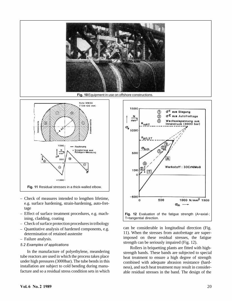
In the manufacture of polyethylene, meanderingtube reactors are used in which the process takes placeunder high pressures (3000bar). The tube bends in this installation are subject to cold bending during manu-facture and so a residual stress condition sets in which
can be considerable in longitudinal direction (Fig.11). When the stresses from autofrettage are super-imposed on these residual stresses, the fatiguestrength can be seriously impaired (Fig. 12).
Rollers in briquetting plants are fitted with high-strength bands. These bands are subjected to specialheat treatment to ensure a high degree of strengthcombined with adequate abrasion resistance (hard-ness), and such heat treatment may result in consider-able residual stresses in the band. The design of the
Vol. 6 No. 2 1989 20
Fig. 10 Equipment in use on offshore constructions.
Fig. 11 Residual stresses in a thick-walled elbow.
Fig. 12 Evaluation of the fatigue strength (A=axial-;T=tangential direction.

rollers must take account of these residual stresses(Fig. 13).
References[1] Tietz, H.D.: Grundlagen der Eigenspannungen, VEB
Deutscher Verlag für Grundstoffindustric, Leipzig(1982).
[2] DIN 8580: Fertigungsverfahren; Übersicht, Ausgabe(1986).
[3] Macherauch, E.: Praktikum in Werkstoffkunde; 6.Auflage, Vieweg-Verlag (1985).
[4] HTM-Sonderdruck, Bd. 31, H. 1 (1976) und H. 2 (1982).
(Received July, 1989)
21 The Rigaku Journal
Fig. 13 Mobile equipment in use on rollers in briketting plants.