no intention of flight
TRANSCRIPT

1© Crown copyright 2021 All times are UTC
AAIB Bulletin: 6/2021 G-EMEB AAIB-26968
INCIDENT Aircraft Type and Registration: Airbus Helicopters EC175B, G-EMEB
No & Type of Engines: 2 Pratt & Whitney Canada PT6C-67E turboshaft engines
Year of Manufacture: 2017 (Serial no: 5030)
Date & Time (UTC): 23 September 2020 at 1000 hrs
Location: Aberdeen Airport
Type of Flight: No intention of flight
Persons on Board: Crew - 2 Passengers - None
Injuries: Crew - None Passengers - N/A
Nature of Damage: Bearing failure within the left accessory gearbox
Commander’s Licence: Airline Transport Pilot’s Licence
Commander’s Age: 37 years
Commander’s Flying Experience: 5,180 hours (of which 1,325 were on type) Last 90 days - 112 hours Last 28 days - 30 hours
Information Source: AAIB Field Investigation
Synopsis
A failure of an alternator pinion roller bearing in the left accessory gearbox (LAGB) occurred during a post-maintenance ground run following a scheduled replacement of the main gearbox. The investigation identified that the roller bearing was subjected to an excessive axial load during operation, caused by compression of grease and air within the alternator shaft link during installation by the operator of a 10 kVA alternator to the LAGB. The cause of the incident was identified as the application of an excessive quantity of grease to the alternator pinion cavity, as required by the aircraft maintenance manual instructions. The method used by the operator to attach the alternator to the left accessory gearbox was identified as a contributory factor in the incident.
The manufacturer has amended the content of the aircraft maintenance manual to ensure that any excess grease is removed from the alternator shaft link cavity and has communicated this information by issuing a Safety Information Notice1 to EC175 operators.
Introduction
The bearing failure occurred whilst the helicopter was on a maintenance ground run with no intention of flight. However, given the circumstances of the failure, and the possibility
Footnote1 SIN 3599-S-63.

2© Crown copyright 2021 All times are UTC
AAIB Bulletin: 6/2021 G-EMEB AAIB-26968
that it could have occurred in flight, the Chief Inspector of Air Accidents instigated a safety investigation to determine the cause.
Maintenance activity
Replacement of the main gear box
The helicopter was undergoing scheduled maintenance to replace the main gear box (MGB), which had reached its overhaul life of 800 flying hours. An overhauled MGB was supplied to the operator by the helicopter manufacturer2. Before this could be installed on G-EMEB, certain accessory equipment had to be removed from the old MGB for installation on the new MGB, including the LAGB 10 kVA alternator.
The exchange of the MGB accessory equipment took place in the operator’s maintenance hangar with both MGBs mounted in transport stands, which provided good access for the work carried out. A Part-66 B1 licenced aircraft engineer (LAE), who was type-rated on the EC175, removed the alternator from the old LAGB, together with its V-band clamp and interface spacer as an assembly, by unfastening the four bolts that attach the interface spacer to the LAGB (Figure 1).
Figure 1
10 kVA alternator, V-band clamp and interface spacer (image used with permission of Airbus Helicopters)
Footnote2 As part of the manufacturer’s MGB overhaul process, the MGB (with the left and right accessory gearboxes
attached) had been run on a test cell with no faults identified. In addition, the overhauled left accessory gearbox had been run on a separate test cell for 12 hours with a power of 30 kW applied, which is higher than the maximum power of the 10 kVA alternator. The power applied on this test cell was cyclically varied (to introduce a cyclical torque loading to the gearbox), again with no faults identified.
3© Crown copyright 2021 All times are UTC
AAIB Bulletin: 6/2021 G-EMEB AAIB-26968
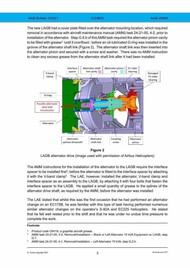
The new LAGB had a cover plate fitted over the alternator mounting location, which required removal in accordance with aircraft maintenance manual (AMM) task 24-21-00, 4-2, prior to installation of the alternator. Step G.6.b of this AMM task required the alternator pinion cavity to be filled with grease3 ‘until it overflows’, before an oil-lubricated O-ring was installed in the groove of the alternator shaft link (Figure 2). The alternator shaft link was then inserted into the alternator pinion and secured with a screw and washer. There was no AMM instruction to clean any excess grease from the alternator shaft link after it had been installed.
Figure 2LAGB alternator drive (image used with permission of Airbus Helicopters)
The AMM instructions for the installation of the alternator to the LAGB require the interface spacer to be installed first4, before the alternator is fitted to the interface spacer by attaching it with the V-band clamp5. The LAE, however, installed the alternator, V-band clamp and interface spacer as an assembly to the LAGB, by attaching it with four bolts that fasten the interface spacer to the LAGB. He applied a small quantity of grease to the splines of the alternator drive shaft, as required by the AMM, before the alternator was installed.
The LAE stated that whilst this was the first occasion that he had performed an alternator change on an EC175B, he was familiar with this type of task having performed numerous similar alternator changes on the operator’s S-92A and EC225 helicopters. He stated that he felt well rested prior to the shift and that he was under no undue time pressure to complete the work.
Footnote3 Product code CM116, a graphite aircraft grease.4 AMM task 24-21-00, 4-2, Removal/Installation – Blank or Left Alternator 10 kVA Equipment on LAGB, step
G.7.5 AMM task 24-21-00, 4-1, Removal/Installation – Left Alternator 10 kVA, step G.2.h.

4© Crown copyright 2021 All times are UTC
AAIB Bulletin: 6/2021 G-EMEB AAIB-26968
Engine ground runs
Following completion of the MGB replacement, G-EMEB was moved to an apron for a ground run6, with no intention of flight. The commander did not identify any abnormalities during his external walk-round inspection and stated that the MGB oil was at the correct level. The No 1 engine was started, and one minute later the MGB BACKUP OIL amber warning caption illuminated. The crew consulted the XMSN page on the multi-function display and noted that the MGB backup oil pressure was briefly 0.2 bar, before it then jumped to the normal value of 2.6 bar, where it remained. All other MGB parameters were in the normal range. The commander then started the No 2 engine.
The ground run proceeded uneventfully with the main rotors running in flat pitch until 18 minutes after the No 1 engine start, when the XMSN CHIP amber warning caption illuminated. The flight crew consulted the electronic checklist and identified that the warning had been triggered by the LAGB chip detector. The commander shut down both engines. Following the ground run, difficulty was experienced in attempting to turn the main rotors by hand in the driven direction, and a “crunching” sound could be heard from the left side of the MGB. The MGB oil was drained and was notably discoloured. The MGB assembly, including the LAGB and right accessory gearbox (RAGB), was sent to the manufacturer for examination.
Main gearbox
Overview
The EC175B MGB is a modular design with a main module that transmits the power from both engines to the main and tail rotors. The LAGB is located on the rear left side of the MGB and is driven by the main module via the left freewheel pinion. The LAGB consists of a train of spur gears within a casing, which rotate the backup oil pump, the No 1 main hydraulic pump, the No 1 air conditioning compressor, the MGB oil cooler fan and the 10 kVA alternator7.
The drive for the DC generator on the RAGB is of a similar design to the LAGB alternator. The RAGB provides drive to the No 2 main hydraulic pump, No 2 air conditioning compressor and the emergency DC generator.
Alternator
The alternator is driven by an alternator pinion and an alternator shaft link (Figure 2) which has an internally-splined cavity that engages with the external splines on the alternator driveshaft. The alternator shaft link has a splined connection with the alternator pinion and is secured to it by a screw and washer. The alternator driveshaft has an oil-lubricated O-ring that is an interference fit within the end bore of the alternator shaft link. This O-ring seals the alternator shaft link internal cavity when the components are assembled.
Footnote6 AMM task 63-00-00, 6-1, Check after maintenance work7 The 10 kVA alternator is optional equipment for EC175s and is used to power the anti-ice system.

5© Crown copyright 2021 All times are UTC
AAIB Bulletin: 6/2021 G-EMEB AAIB-26968
Bearing arrangement
The alternator pinion is located and supported in the LAGB casing by two identical roller bearings: the F1 bearing at the rear end and the F2 bearing at the forward end of the pinion. The F1 and F2 roller bearings are designed to principally accommodate radial loads and are only rated at 10% of the radial load capacity when loaded in the axial direction. The F1 and F2 bearings were replaced with new parts when the LAGB was overhauled, prior to its installation on G-EMEB.
Alternator clamping distances
The manufacturer stated that the maximum possible clamping distance between the alternator and the interface spacer, when using the V-band clamp to attach them together, was 3.6 mm, (Figure 3(a)). The maximum clamping distance when attaching the alternator, V-band clamp and interface spacer to the LAGB as an assembly was 14.4 mm, four times greater than when using the V-band clamp (Figure 3(b)).
Figure 3
Maximum clamping distances using the V-band clamp and interface spacer bolts

6© Crown copyright 2021 All times are UTC
AAIB Bulletin: 6/2021 G-EMEB AAIB-26968
Displacement of grease
The volume of grease displaced from the alternator pinion cavity, due to insertion of the alternator shaft link and screw, is approximately 70% greater than the volume available within the shaft link cavity once the alternator is mounted on the LAGB (shaded green in Figure 2).
The volume of grease remaining within the shaft link cavity once the alternator is mounted is influenced by the following factors:
● The degree to which the alternator pinion cavity was initially filled with grease, prior to insertion of the alternator shaft link.
● The amount of grease removed from the alternator shaft link cavity on the socket used to tighten the alternator shaft link screw.
● Any grease extruded outside the alternator shaft link, upon its insertion.
● Any excess grease cleaned away from the alternator shaft link cavity prior to installation of the alternator.
MGB examination
Magnetic chip detectors
Metallic particles were found on magnetic chip detector (MCD) No 4, in the LAGB sump, and MCD No 6, in the MGB oil sump. Metallurgical analysis of this debris determined that it was 100C6 steel alloy, the bearing material used in the F1 bearing. Excessive axial and radial play were noted in the alternator pinion shaft, due to loss of location of the alternator pinion at the failed F1 bearing.
Bearings
The LAGB outer casing was removed and visual examination confirmed that the F1 bearing had overheated and the bearing rollers were significantly deformed, with evidence of roller skidding (Figure 4). All the bearing rollers remained within the F1 bearing. The bearing cage, which is formed from a PEEK8 material, was found in the LAGB sump. It had deformed due to excessive temperature and had migrated from the bearing.
The end of the alternator pinion that is supported by the F1 bearing was also heat-distressed and the pinion shoulder, at the point of engagement with the F1 bearing, showed evidence of creep and wear (Figure 5). The nature of this damage was consistent with the pinion running in the overheated F1 bearing whilst subject to a compressive axial load.
Footnote
8 Polyether ether ketone, an organic thermoplastic polymer.

7© Crown copyright 2021 All times are UTC
AAIB Bulletin: 6/2021 G-EMEB AAIB-26968
Figure 4Failed F1 bearing in the LAGB (image used with permission of Airbus Helicopters)
Figure 5Damaged alternator pinion (image used with permission of Airbus Helicopters)

8© Crown copyright 2021 All times are UTC
AAIB Bulletin: 6/2021 G-EMEB AAIB-26968
Alternator examination
The alternator was examined at the equipment manufacturer. The alternator conformed to all dimensional requirements apart from a minor variance between the mating flange and the rear cover, which had no influence on the F1 bearing failure. Visual examination of the alternator revealed that it was in good condition and the two ball bearings that support the alternator rotor were also in good condition, with no excessive or abnormal wear. The static electrical values measured were compliant with the requirements stated in the alternator component maintenance manual. It was determined that the alternator was serviceable and free from any defect that could result in an axial load being applied to the alternator pinion within the LAGB.
Testing by the manufacturer
The manufacturer conducted a test in which the installation of an alternator was attempted on an LAGB where the alternator shaft link cavity was completely filled with grease. In this condition the alternator could not be installed, as the gap between the alternator and the interface spacer was too large for the V-band clamp to engage.
After removing a small amount of grease from the alternator shaft link cavity, installation of the alternator was possible, with a small gap of 1-2 mm remaining between the alternator and the interface spacer due an excessive quantity of grease. Once the V-band clamp was installed and tightened to the AMM torque figure of 6.8 Nm, this gap had closed and it was observed that the LAGB drive had become notably difficult to turn by hand, which is an abnormal condition. The increased resistance in the LAGB drive was due to an excessive compressive axial load introduced in the alternator pinion, due to compression of the grease and air trapped within the sealed alternator shaft link as the alternator had been clamped to the LAGB.
Backup oil pressure warnings
The manufacturer stated that backup oil pressure warnings on the first runs of MGBs had been observed on other EC175s with other operators. The transient warning is due to gearbox oil displacing air within the gearbox oil distribution system when an MGB is first run. This air-purging effect had no influence on the failure of the F1 bearing.
Hazard assessment
The manufacturer performed a hazard assessment to consider the effect of a similar failure occurring in flight. The hazard assessment included a jam occurring in the LAGB leading to the loss of drive to the backup oil pump, No 1 hydraulic pump, cabin air conditioning compressor, MGB cooling fan and 10 kVA alternator. This scenario was considered to be conservative by the manufacturer in their assessment of the hazards, as its stress analysis showed that should the alternator pinion jam, the gear teeth on the pinion would fail, allowing drive to continue to the other LAGB accessories.
The loss of each of the LAGB accessories would be detected by the aircraft’s caution and warning system, with each failure generating an amber warning caption. The hazard

9© Crown copyright 2021 All times are UTC
AAIB Bulletin: 6/2021 G-EMEB AAIB-26968
assessment concluded that the severity level of this failure scenario was ‘MAJOR’, resulting from a significant erosion of safety margins, and that the occurrence level was ‘REASONABLY PROBABLE’ with a probability of occurrence between 10-5 and 10-3 per flight hour. The hazard assessment therefore concluded that no resulting unsafe condition9 was identified.
The published flight manual procedure would require the flight crew to reduce engine power and fly at a minimum speed of 130 KIAS, to ensure sufficient cooling airflow through the MGB oil cooler, and to limit the flight duration. The operator’s Emergency Checklist would require the crew to ‘land as soon as possible’ at the nearest site where a safe landing could be carried out.
Analysis
Since the LAGB had successfully run on a test cell for 12 hours without any deterioration detected in the alternator pinion bearings, with a 10 kVA alternator installed, it is likely that the installation of the 10 kVA alternator by the operator directly influenced the F1 bearing failure that occurred after 18 minutes of the post-maintenance ground run.
Examination of the failed F1 bearing and alternator pinion revealed that they had been subjected to a compressive axial load during the ground run. This axial load was greater than the ability of the F1 roller bearing to withstand it, leading to the bearing overheating and causing the PEEK bearing cage to melt, which was then extruded from the bearing. The overheating also caused significant wear of the bearing rollers, releasing bearing debris into the MGB oil system and causing discolouration of the MGB oil.
Testing conducted by the manufacturer showed that an excessive quantity of grease within the alternator shaft link cavity can create a significant compressive axial load on the alternator pinion when the alternator is clamped to the LAGB. This is due to compression of the excess grease and air within the sealed shaft link cavity acting as a hydraulic piston. This loading case was unintended and had not been anticipated when the LAGB components and associated AMM maintenance procedures were developed.
The method of attaching the alternator to the LAGB used by the operator’s LAE meant that the compression of the grease and air within the shaft link cavity was up to four times greater than would have been the case if the method specified in the AMM had been followed.
The manufacturer stated that the reason for filling the alternator pinion cavity with sufficient grease to cause it to overflow was to ensure that grease remained within the alternator pinion splined area during the in-service period between overhauls, to ensure lubrication of the splines.
This large quantity of grease, combined with the sealed design of the alternator shaft link cavity once the alternator driveshaft was inserted, created a latent condition in which an unwanted axial load could be introduced into the alternator pinion and F1 roller bearing.Footnote9 As defined in EASA AMC 21.A.3B(b).

10© Crown copyright 2021 All times are UTC
AAIB Bulletin: 6/2021 G-EMEB AAIB-26968
Safety action
In response to this incident the manufacturer released Safety Information Notice (SIN) 3599-S-63, alerting EC175 operators to the potential hazard of excessive grease within the alternator shaft link cavity. The manufacturer has also revised the content of AMM tasks 24-21-00, 4-1 (Removal/Installation – Left Alternator 10 kVA) and 24-21-00, 4-2 (Removal/Installation – Blank or Left Alternator 10 kVA Equipment on LAGB), requiring that any excess grease is removed from the shaft link cavity prior to installation of the alternator on the LAGB. The SIN also highlighted the need to follow the published AMM procedure when installing the alternator, by attaching it using the V-band clamp.
As the mounting of the DC generator on the RAGB has a similar design to the 10 kVA alternator, the manufacturer also revised the related AMM installation procedures for the DC generator.
Second event
The AAIB received a report of a second event involving an EC175B that took place on 9 March 2021, in which an LAGB alternator pinion bearing failure occurred during a ground run following the scheduled replacement of the MGB assembly. Investigation by the operator10 revealed similar circumstances to the G-EMEB event, as excessive grease had been applied to the alternator pinion cavity and the alternator, V-band clamp and interface spacer had been mounted to the LAGB as an assembly, rather than by the method required in the AMM. This event occurred after the issue of Safety Information Notice 3599-S-63. The operator stated that it will issue a reminder to its maintenance personnel.
Conclusion
The failure of the F1 bearing was caused by an axial load applied to the roller bearing in excess of the bearing’s rated capacity. The axial load occurred due to the compression of excess grease and air within the sealed alternator shaft link cavity when the alternator was mounted to the LAGB. The method used to mount the alternator to the LAGB was not in accordance with the instructions in the AMM. This contributed to the generation of the axial load, which was up to four times greater than would have been the case had the AMM instructions been followed.
The manufacturer has amended the content of the AMM to ensure that any excess grease is removed from the alternator shaft link cavity and has communicated this information by issuing a Safety Information Notice to EC175 operators.
Published: 22 April 2021.
Footnote10 The operator involved in this second event was different to the operator of G-EMEB.