flight second stage regulator - scubasparesscubaspares.com/manuals/ap4498.pdf · 2 flight second...
TRANSCRIPT

FLIGHT SECOND STAGE REGULATOR
TECHNICAL SUPPORT
APEKS MARINE EQUIPMENT LTD, NEPTUNE WAY, BLACKBURN, LANCASHIRE. BB1 2BTTel: 0044 (0) 1254 692200 Fax: 0044 (0) 1254 692211 E-mail: [email protected] Web: www.apeks.co.uk
MAINTENANCE MANUAL FOR
AUTHORISED TECHNICIANS
Document No. AP4498 Issue 928/11/2011

2
FLIGHT Second Stage Regulator Maintenance Manual
Change No.
Change Request No.
Description & Comments: Change Date New Issue No. Changed By:
Approved By:
1116 0247 Add details of new O ring pick 16/02/11 06 RH ACD
1158 NA Added note for removing purge clamp ring 16/09/11 07 AB ACD
1175 NA Added Twilight Pt no to Drawing 28/10/11 08 AB ACD
1178 NA Added details of new new silicone seating 28/11/11 09 AB ACD
Amendments record:
Amendments and approval of this document can only be carried out by the relevant people listed on the Approved list of signatures, which is listed in the Apeks Quality Manual. To instigate a change, a Task / Change request form, (Form No. ‘DESI/10002’), must be completed and passed to the relevant person(s) for approval which are listed on the Approved List of Signatures. When approval has been granted and recorded this table can then be completed and the document up issued.

3
FLIGHT Second Stage Regulator Maintenance Manual
ContentsCOPyRIGHT NOTICE .......................................................................................................................................................................................................3
INTRODUCTION ...............................................................................................................................................................................................................3
WARNINGS, CAUTIONS & NOTES ..............................................................................................................................................................................3
SCHEDULED SERvICE .....................................................................................................................................................................................................3
GENERAL GUIDELINES ...................................................................................................................................................................................................3
GENERAL CONvENTIONS .............................................................................................................................................................................................4
DISASSEMBLy PROCEDURES ......................................................................................................................................................................................4
INSPECTION PROCEDURES..........................................................................................................................................................................................7
REASSEMBLy PROCEDURES ........................................................................................................................................................................................8
TESTING ............................................................................................................................................................................................................................ 10
TABLE 1 - TROUBLSHOOTING GUIDE .................................................................................................................................................................... 13
TABLE 2 - RECOMMENDED TOOL LIST ................................................................................................................................................................. 14
TABLE 3 - RECOMMENDED LUBRICANTS AND CLEANERS .......................................................................................................................... 15
CLEANING AND LUBRICATION PROCEDURE ..................................................................................................................................................... 16
TABLE 4 -TORQUE SPECIFICATIONS ...................................................................................................................................................................... 17
TABLE 5 - TEST BENCH SPECIFICATIONS ............................................................................................................................................................. 17
FLIGHT ExPLODED PARTS DRAWING ................................................................................................................................................................... 18
4
FLIGHT Second Stage Regulator Maintenance Manual
COPyRIGHT NOTICEThis manual is copyrighted, all rights reserved. It may not, in whole or in part, be copied, photocopied, reproduced, translated, or reduced to any electronic medium or machine readable form without prior consent in writing from Apeks Marine Equipment Ltd. It may not be distributed through the internet or computer bulletin board systems without prior consent from Apeks Marine Equipment Ltd.
©2010 Apeks Marine Equipment Ltd.
Flight Seond Stage Maintenance Manual
(AP4498 Issue 9 )
INTRODUCTIONThis manual provides factory prescribed procedures for the correct maintenance and repair of the Apeks Flight second stage regulators. It is not intended to be used as an instructional manual for untrained personnel. The procedures outlined within this manual are to be performed only by personnel who have received factory authorised training through an Apeks Service & Repair Seminar. If you do not completely understand all of the procedures outlined in this manual, contact Apeks to speak directly with a Technical Advisor before proceeding any further.
WARNINGS, CAUTIONS & NOTESPay special attention to information provided in warnings, cautions, and notes that are accompanied by one of these symbols:
WARNINGS indicate a procedure or situation that may result in serious injury or death if instructions are not followed correctly.
CAUTIONS indicate any situation or technique that will result in potential damage to the product, or render the product unsafe if instructions are not followed correctly.
NOTES are used to emphasise important points, tips, and reminders.
SCHEDULED SERvICEIt is recommended that the Apeks Flight second stage regulators should be examined annually regardless of usage.
However, If at all unsure about the correct functioning of the Apeks second stage, then it must be officially inspected immediately.
All service and inspection details need to be documented in the Regulator Service Record in the back of the Owner’s Manual to keep the Limited Lifetime Warranty in effect.
3. Checking for opening effort that is within the acceptable range.
4. Checking for smooth operation of the venturi switch.
5. A visual inspection of any filters for debris or dis-colouration.
6. Pulling back hose protectors and checking that the hoses are secure in the hose crimps.
7. A visual inspection of the exhaust valve(s) to see that they are in good condition and that it is seating against a clean and undamaged surface.
8. A visual inspection of the mouthpiece looking for tears or holes and checking the general condition.
9. A visual inspection of the Slide Locking Ring. Check that the Ring is in good condition with no cracks or splits. Ensure that the two teeth are in good condition and that the Hose Nut cannot be unscrewed without squeezing the Ring.
If a regulator fails steps 1,2,3,4 or 9 the entire regulator should be serviced. If a regulator fails 5,7 or 8 it will be up to the technician’s discretion whether or not a full service is required.
Failure of step 6 requires replacement of the Hose.
GENERAL GUIDELINES1. In order to correctly perform the procedures outlined
in this manual, it is important to follow each step exactly in the order given. Read over the entire manual to become familiar with all procedures and to learn which specialty tools and replacement parts will be required before commencing disassembly. Keep the manual open beside you for reference while performing each procedure. Do not rely on memory.
2. All service and repair should be carried out in a work area specifically set up and equipped for the task. Adequate lighting, cleanliness, and easy access to all required tools are essential for an efficient repair facility.
3. During disassembly, reusable components should be segregated and not allowed to intermix with non-reusable parts or parts from other units. Delicate parts, including inlet fittings and valve seats which contain critical sealing surfaces, must be protected and isolated from other parts to prevent damage during the cleaning procedure.
4. Use only genuine Apeks parts provided in the Flight 2nd stage service kit (AP0254). DO NOT attempt to substitute an Apeks part with another manufacturer’s, regardless of any similarity in shape or size.
5. Do not attempt to reuse mandatory replacement parts under any circumstances, regardless of the amount of use the product has received since it was manufactured or last serviced.
6. When reassembling, it is important to follow every torque specification prescribed in this manual, using a calibrated torque wrench. Most parts are made of either marine brass or plastic, and can be permanently damaged by undue stress.
An Official Inspection consists of:1. A pressurised immersion test of the entire unit to check for air
leakage.
2. Checking for stable medium pressure that is within the acceptable range.

5
FLIGHT Second Stage Regulator Maintenance Manual
Pinch MethodPress upwards on
sides of ‘O’ Ring to create a protrusion.
Grab ‘O’ Ring or insert ‘O’ Ring tool
at protrusion.
Removal of hose
Removal of Exhaust Tee
GENERAL CONvENTIONSUnless otherwise instructed, the following terminology and techniques are assumed:1. When instructed to remove, unscrew, or loosen a
threaded part, turn the part anti-clockwise.
2. When instructed to install, screw in, or tighten a threaded part, turn the part clockwise.
3. When instructed to remove an ‘O’ Ring, use the pinch method (see figure below) if possible, or use a brass, aluminium or plastic ‘O’ Ring removal tool. Avoid using hardened steel picks, as they may damage ‘O’ Ring sealing surfaces. All ‘O’ Rings that are removed are discarded and replaced with brand new ‘O’ Rings.
4. The following acronyms are used throughout the manual: MP is Medium Pressure; HP is High Pressure; PN is Part Number.
5. Numbers in parentheses reference the key numbers on the exploded parts schematics. For example, in the statement, “...remove ‘O’ ring (11) from...”, the number 11 is the key number to the Inlet Fitting ‘O’ Ring.
DISASSEMBLy PROCEDURES NOTE: Before performing any disassembly, refer
to the exploded parts drawing, which references all mandatory replacement parts. These parts should be replaced with new, and must not be reused under any circumstances - regardless of the age of the regula-tor or how much use it has received since it was last serviced.
CAUTION: Use only a plastic, brass or aluminium ‘O’ Ring removal tool (PN AT79) when removing ‘O’ Rings to prevent damage to the sealing surface. Even a small scratch across an ‘O’ Ring sealing surface could result in leakage. Once an ‘O’ Ring sealing surface has been damaged, the part must be replaced with new. DO NOT use a dental pick, or any other steel instrument.
2. Pull back the Hose Pro-tector and inspect the Hose Crimps. If either Crimp is damaged or the Hose is pulling out of the crimp then the Hose must be replaced.
1. Pull back the Hose Protector, pinch the Locking Slide Ring (19) on the opposing grips, and unscrew the hose from the second stage. Remove the ‘O’ ring from inside the Hose Swivel. Exercise caution not to scratch the ‘O’ ring groove. Remove the ‘O’ ring from the Hose Nut end of the Hose.
3. Place one finger into each side of the Exhaust Tee (8) and squeeze them together. Pull the Exhaust Tee away from the Case (6).
CAUTION: DO NOT use any tools to remove the Hose. The connection has been designed to be operated by hand only.
NOTE: When servicing flight regulators it is good practice to follow the sequence of operations stated below:1) Strip down both the 1st stage and 2nd stage2) Clean and inspect all regulator parts as laid out in the procedures in both manuals.3) Reassemble the 2nd stage (but do not adjust or set)4) Reassemble and set the 1st stage (following procedures as laid out in the 1st stage manual)5) Set the 2nd stage (following procedures as laid out in the manual).
The reason for leaving the 2nd stage before setting is to allow the seating area to “seat and bed in” better, therefore optimising performance and adjustment.

6
FLIGHT Second Stage Regulator Maintenance Manual
Removal of Mouthpiece
4. Unfasten the Mouthpiece Clip (12) and pull the Mouthpiece off the Case(6)
5. To remove the Purge Clamp Ring (1) squeeze at the positions shown on the photo below and turn anti-clockwise. Separate the Purge Clamp Ring (1) from the Front Cover Assy (2) and the Case (6).
8. Remove the ‘O’ ring from the venturi Lever (10) taking care not to scratch the ‘O’ ring Groove.
6. Locate the three kidney shaped pegs of the AT71 Locking Ring Tool into the slots of the Inner Locking Ring (3). Unscrew the Inner Locking Ring (3). Remove the Friction Ring (4) and the Diaphragm (5) from inside of the Case (6).
7. To remove the venturi Lever (10) from the Case (6), position the lever vertically as shown below. Locate the venturi lever removal tool (AT77) on the venturi lever side first, then press down on the opposite side to push out the venturi lever.
9. Remove the Sliding Locking Ring (19)by pulling in an axial direction away from the case and gently rocking side to side to loosen the component.
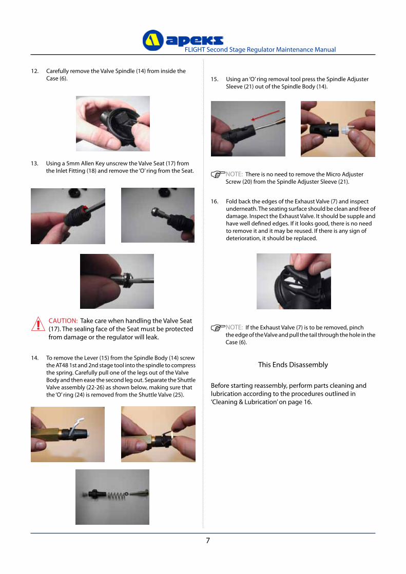
11. To remove the spindle body (14) from the case (6) use the opposite end of the cracking effort adjuster tool to push it out.
10. To remove the inlet fitting (18) use the venturi combination tool (AT77), align the grooves on the tool with those on the fitting and turn in an anti clockwise direction to unscrew. once satisfied that the thread has disengaged, the inlet fitting may require a little pull as the O ring will be holding it in the bore of the case. Once the inlet fitting has been removed from the case, carefully remove the O ring, taking care not to scratch the O ring groove.
CAUTION: Take care not to damage or distort the Lever (15) when removing the venturi Lever (10). DO NOT depress the tab of the venturi Lever too far, as this will result in permanent deformation.
WARNING: Do not use any other method or tool to unscrew or tighten the inlet fitting
NOTE: A latex grip glove i.e an Arco Gripz or an equivalent product will aid the removal of the purge ring.
7
FLIGHT Second Stage Regulator Maintenance Manual
This Ends Disassembly
Before starting reassembly, perform parts cleaning and lubrication according to the procedures outlined in ‘Cleaning & Lubrication’ on page 16.
13. Using a 5mm Allen Key unscrew the valve Seat (17) from the Inlet Fitting (18) and remove the ‘O’ ring from the Seat.
14. To remove the Lever (15) from the Spindle Body (14) screw the AT48 1st and 2nd stage tool into the spindle to compress the spring. Carefully pull one of the legs out of the valve Body and then ease the second leg out. Separate the Shuttle valve assembly (22-26) as shown below, making sure that the ‘O’ ring (24) is removed from the Shuttle valve (25).
15. Using an ‘O’ ring removal tool press the Spindle Adjuster Sleeve (21) out of the Spindle Body (14).
12. Carefully remove the valve Spindle (14) from inside the Case (6).
CAUTION: Take care when handling the valve Seat (17). The sealing face of the Seat must be protected from damage or the regulator will leak.
NOTE: There is no need to remove the Micro Adjuster Screw (20) from the Spindle Adjuster Sleeve (21).
16. Fold back the edges of the Exhaust valve (7) and inspect underneath. The seating surface should be clean and free of damage. Inspect the Exhaust valve. It should be supple and have well defined edges. If it looks good, there is no need to remove it and it may be reused. If there is any sign of deterioration, it should be replaced.
NOTE: If the Exhaust valve (7) is to be removed, pinch the edge of the valve and pull the tail through the hole in the Case (6).
8
FLIGHT Second Stage Regulator Maintenance Manual
INSPECTION PROCEDURES
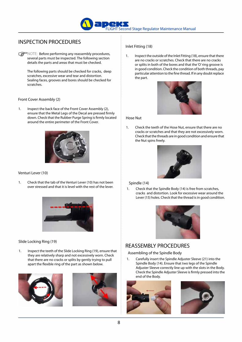
NOTE: Before performing any reassembly procedures, several parts must be inspected. The following section details the parts and areas that must be checked.
The following parts should be checked for cracks, deep scratches, excessive wear and tear and distortion.Sealing faces, grooves and bores should be checked for scratches.
Front Cover Assembly (2)
1. Inspect the back face of the Front Cover Assembly (2), ensure that the Metal Legs of the Decal are pressed firmly down. Check that the Rubber Purge Spring is firmly located around the entire perimeter of the Front Cover.
venturi Lever (10)
1. Check that the tab of the venturi Lever (10) has not been over stressed and that it is level with the rest of the lever.
Slide Locking Ring (19)
1. Inspect the teeth of the Slide Locking Ring (19), ensure that they are relatively sharp and not excessively worn. Check that there are no cracks or splits by gently trying to pull apart the flexible ring of the part as shown below.
Inlet Fitting (18)
1. Inspect the outside of the Inlet Fitting (18), ensure that there are no cracks or scratches. Check that there are no cracks or splits in both of the bores and that the ‘O’ ring groove is in good condition. Check the condition of both threads, pay particular attention to the fine thread. If in any doubt replace the part.
Hose Nut
1. Check the teeth of the Hose Nut, ensure that there are no cracks or scratches and that they are not excessively worn. Check that the threads are in good condition and ensure that the Nut spins freely.
Spindle (14) 1. Check that the Spindle Body (14) is free from scratches,
cracks and distortion. Look for excessive wear around the Lever (15) holes. Check that the thread is in good condition.
REASSEMBLy PROCEDURES
1. Carefully insert the Spindle Adjuster Sleeve (21) into the Spindle Body (14). Ensure that two legs of the Spindle Adjuster Sleeve correctly line up with the slots in the Body. Check the Spindle Adjuster Sleeve is firmly pressed into the end of the Body.
Assembling of the Spindle Body

9
FLIGHT Second Stage Regulator Maintenance Manual
2. Install a new lubricated ‘O’ ring (24) onto the Spring Carrier (22). Check the bore of the Shuttle valve (25) to ensure that the old ‘O’ ring has been removed. Insert the Spring Carrier (22) into one end of the Spring (23) and the Shuttle valve (25) into the other, carefully guiding the end of the Carrier into the bore of the Shuttle valve.
3. Insert the Spring Carrier end of the assembly into the Spindle Body (14). Screw in the AT48 tool to fully compress the Spring until it passes the triangular shaped hole in the Body. (Please note: it may be necessary to do this with the grey silicone seat (26) in place. Insert the feet of the Lever (15) into the gap, this retains the Shuttle valve inside the Body .
CAUTION: Ensure that the Lever is not twisted and that legs are parallel. Lever should appear as that shown on the left, not as shown on the right. If necessary, gently squeeze legs together to straighten.
NOTE: Ensure that the Lever has a full range of movement and does not catch on the valve Spindle Body. Ensure that the spring can be seen through the valve Spindle Hole.
NOTE: Please take note of what type of spring carrier is inside the regulator (Dot or No Dot see pictures below) as this will affect the setting procedure. (see 2nd stage opening effort procedure)
Dot No Dot
CAUTION: Take care not to damage the Silicone seating (26).
NOTE: When fitting the new seat (26) only use the grey silicone seating (pt no129638). Older Flight models may have the standard black rubber seat fitted (pt no AP2034) please discard as these are no longer used on the Flight 2nd stage.
Grey Silicone Seat Black Rubber Seat

10
FLIGHT Second Stage Regulator Maintenance Manual
Fitting Spindle Assembly into Case
4. Carefully insert a new Silicone Seating (26) into the end of the Shuttle valve (25) .(If not already)
CAUTION: Use only the end of your finger to insert the new Silicone seating (26), NOT your finger nail. DO NOT mark the face of the Silicone seating, this will cause the 2nd stage to leak when fully assembled.
5. Insert the Spindle Body assembly into the Case. Using the opposite end of the cracking effort adjuster tool (AT76) Push the Body firmly into the Case ensuring that there is no gap between the two parts. Ensure that the Lever has a full range of movement and does not catch on the valve Spindle Body.
6. Install a new Lubricated ‘O’ ring (16) onto the valve Seat (17). Carefully push the valve Seat (17) into the smaller diameter bore of the Inlet Fitting (18). Using a 5mm Allen key turn the valve seat counter clockwise until it bottoms out.
7. Install a new Lubricated ‘O’ ring (11) onto the Inlet Fitting (18).
8. Screw the Inlet Fitting (18) into the end of the Spindle Body (14) and hand tighten until the grooves line up. Use the venturi combination tool (AT77)
9. Align the location splines of the Locking Slide Ring (19) to the grooves on the Inlet Fitting (18) and Case (6). Using the palm of your hand carefully push the Locking Slide Ring (19) fully upto the Case (6) until it clicks.
WARNING: Only use the venturi combination tool (AT77) to remover or tighten the inlet fitting. Over tightening of this part will result in damage.
CAUTION: DO NOT use the lever to push the Spindle into the case as this will bend the lever.

11
FLIGHT Second Stage Regulator Maintenance Manual
WARNING: Compressed air can be highly explosive and is dangerous if misused. Ensure the cylinder valve is opened slowly. Use eye and ear personal protective equipment when performing any tests involving compressed air.
10. While holding the Case (6) at eye level, use a 5mm Allen key to screw the valve Seat (17) clockwise until the Lever (15) drops just below the rim of the Case. Check by gently flicking the lever, it should bounce and have free movement. The lever should return to its set position, if it sticks then the lever is not square, fitted incorrectly or it is bent.
11. Refit the Diaphragm (5) into the front of the Case (6). Using your finger carefully work the edges of the Diaphragm into place so it sits evenly in the Case. Insert the Flight Friction Ring (4) into the case. Use the same technique to ensure it sits evenly onto the Diaphragm.
CAUTION: Ensure that the Diaphragm (5) and Flight Friction Ring (4) are seated correctly and are not creased.
CAUTION: Ensure that the Lever (15) moves freely and sits vertically within the case (6).
12. Refit the locking ring ensuring the 3 small grooves are facing up. (see pic below). Using the AT71 Tool slowly screw the Inner Locking Ring (3) into the Case. Hand tighten only. Once the diaphragm is secure, gently grip the diaphragm pad between the thumb and forefinger, and gently pull from side to side to check the diaphragm is secure.
Final Testing
2. Connect the first stage regulator to a calibrated test bench and pressurise the system to 200 (±10) bar.
3. Place the NO GAS FLOW side of the Flight Setting Tool (PN AT75) onto the plastic pad of the Diaphragm (5). Depress the Diaphragm by pushing the tool in until it stops against the Case. If no gas flows from the second stage proceed to step 5. If gas flows from the valve follow step 4.
4. Disconnect the second stage from the hose as shown in step 1 of the disassembly procedure, (excluding ‘O’ ring removal). Using the Flight Inline Adjuster Tool (PN AT72/F) or 5mm Allen key as appropriate, turn the valve Seat (17) clockwise by approximately 1/16 of a turn (see step 12 of the disassembly procedure for Ref.). This lowers the lever inside. Repeat step 2.
Setting the Lever Height
5. Place the GAS FLOW side of the Flight Setting Tool (PN AT75) onto the plastic pad of the Diaphragm (5) as positioned before. Depress the Diaphragm by pushing the tool in until it stops against the Case. If gas flows from the second stage the lever height inside is correct. However, if no gas flows from the valve this means that the lever is now set too low. Proceed to step 6.
1. Refit the hose onto the second stage until it stops. DO NOT use any tools as this will damage the connection. Audible clicks should be heard as the hose is screwed into place. Check that the hose cannot be unscrewed without squeezing the Sliding Locking Ring.
WARNING: Tools are not required for attaching or removing the hose, hand tight is sufficient.
NOTE:
CAUTION: The lever setting tool AT75 should only be used during a full rebuild or when the silicone seating has been replaced. It should not be used for re-adjusting the lever height of returning customer second stages.
When fitting the grey silicone seat the lever height can be set higher and more sensitive and will im-prove the performance of the second stage. This can be done with the new setting tool AT75 marked with ‘B’. The older tool should be discarded.

12
FLIGHT Second Stage Regulator Maintenance Manual
NOTE: Extremely small leaks may be better detected by applying a soap solution or Snoop™ to the leak area. Bubble streams will indicate the source of the leak. Before disassembling to correct any leaks, rinse the entire regulator thoroughly with fresh water and blow out all residual moisture with filtered, low-pressure air. Disassemble and remedy the problem, referring to “Table 1 - Troubleshooting.”
6. Disconnect the second stage from the hose as shown in step 1 of the disassembly procedure. Using the Flight Inline Adjuster Tool (PN AT72/F) or 5mm Allen key as appropriate, turn the valve Seat (17) anti- clockwise by approximately 1/16 of a turn (see step 6 of reassembly procedures for Ref.). Repeat step 2.
1. Insert the Flight Micro Adjuster Tool (AT76) into the open side of the Case (6), making sure that the hexagonal bit engages into the Micro Adjuster Screw (20). Connect the first stage regulator to a calibrated test bench and pressurise the system to 200 (±10) bar. Slowly open the flowmeter control knob (start vacuum) while watching both the magnahelic gauge and the intermediate pressure gauge.
Second Stage Opening Effort Test
2. When the intermediate pressure begins to drop, indicating the second-stage valve is open, the magnahelic gauge should indicate an opening effort of +1.4 in.H2O (3.5mbar) to +1.6 in.H2O (4 mbar). If the reading is outside of these specifications, adjust the Micro Adjuster Screw (20), turning anti-clockwise to lower the opening effort or clockwise to increase the opening effort. If this fails to give the correct reading refer to “Table 1 - Troubleshooting” for corrective actions.
1. After disconnecting the regulator from the flow bench, connect it to a gas cylinder filled to approximately 200 bar. Open the cylinder valve to repressurise the regulator, and submerge the entire system in a test tank of clean water.
External Leak Test
2. Observe any bubbles arising from the submerged regulator over a one minute period. The recommended time is necessary due to slower bubble formation that occurs in smaller leaks. Bubbles indicate a leak, which requires the system to be disassembled at the source to check sealing surfaces, assembly sequence and component positioning in order to correct the problem(s).
NOTE: It is important to ensure that the rim of the AT71 Flight Setting Tool is concentric with the Case (6). If the Tool is misaligned it will not measure the diaphragm travel correctly and therefore, sensitivity.
7. Place the Front Cover Assembly (2) into the front of the Case (6) as shown below. Fit the Purge Clamp Ring (1) over the top of the Front Cover Assembly (2). Rotate the Purge Clamp Ring (1) clockwise until it firmly clicks into place.
NOTE: Regulators with serial numbers from 9104054 to 10044044 will need to be de-pressurised when the second stage opening effort is adjusted, this is to ensure an accurate reading and optimum performance as previously described. These 2nd stages will have a dotted spring carrier fitted.
NOTE:When newly built all regulators will also benefit from being left for a minimum of ten minutes before being pressurised and the opening effort set.

13
FLIGHT Second Stage Regulator Maintenance Manual
Subjective Breathing Test1. Depress the Front Cover Assembly (2) fully to ensure
that an adequate volume of air needed to clear the second stage flows through the mouthpiece. Then, inhale slowly but deeply from the mouthpiece. A properly serviced and adjusted regulator should deliver air upon deep inhalation without excessive inhalation effort, freeflow, or “fluttering” of the second-stage diaphragm. When exhaling, there should be no fluttering or sticking of the exhalation valve. If any of these problems occur, refer to “Table 1 - Troubleshooting”.
This Ends Reassembly
2. With the venturi Lever set to the + position tap the Front Cover Assembly (2) quickly, this should cause the regulator to freeflow. Stop the freeflow after a couple of seconds by placing a hand over the mouthpiece.
2. If equipped with a Comfo-bite Mouthpiece, make sure the ‘bridge’ of the Mouthpiece (13) is facing upward. Stretch the Mouthpiece over the second-stage Mouthpiece outlet port. At the base of the Mouthpiece is a groove for the Mouthpiece Clip (12). Wrap the Clip around the Mouthpiece so that the buckle points toward the Hose. Fasten the Clip, ensuring that the Mouthpiece (13) is securely held in place.
3. Locate the bottom of the Flight Exhaust Tee (8) onto the Case (6). Place a thumb in each exhaust port and push the Tee towards the mouthpiece. Ensure that the Tee fits over the Case and is secure. Taking care not to damage or dislodge the exhaust valve.
NOTE: To check that the Diaphragm has sealed correctly, place your thumb over the end of the Inlet Fitting with the hose removed (see paragraph 1 in disassembly to remove and paragraph 1 in final testing to refit) . Suck and hold at the mouthpiece port, a vacuum should be held without any leakage.
Final Assembly1. Install a new lubricated ‘O’ ring (11) onto the venturi Lever
(10). Align the venturi Lever in a vertical position with the Case and using the palm of your hand press the lever into place. Ensure that the venturi Lever rotates freely and feels secure.

14
FLIGHT Second Stage Regulator Maintenance Manual
Table 1 - Troubleshooting Guide
SyMPTOM POSSIBLE CAUSE TREATMENT
Leakage or freeflow from Flight Second Stage
1. Excessively high first-stage intermediate pressure.
1. Refer to first-stage Troubleshooting Guide.
2. Rubber (Black) or Silicone seating (26) damaged or worn. 2. Replace with Silicone Seating.
3. valve Seat (17) adjusted incorrectly, Lever (15) set too high.
3. Reset Seat preliminary settings, and repeat Adjustment Procedures.
4. Lever (15) bent. 4. Replace Lever.
5. valve Seat (17) sealing surface damaged. 5. Replace valve Seat.
6. Spring (23) damaged. 6. Replace Spring.
7. Shuttle valve ‘O’ Ring (24) damaged. 7. Replace ‘O’ Ring.
8. Shuttle valve (25) bore damaged. 8. Replace Shuttle valve.
9. venturi Lever ‘O’ Ring (11) damaged. 9. Replace ‘O’ Ring.
Low purge or excessive work of breathing (full cylinder)
1. Low first-stage intermediate pressure. 1. Refer to first-stage Troubleshooting Guide.
2. Seat (17) adjusted incorrectly, Lever (15) set too low.
2. Reset Seat preliminary settings, and repeat Adjustment Procedures.
3. Intermediate pressure hose clogged or obstructed. 3. Clean or replace Hose.
4. Black rubber seating fitted4. Replace with silicone seating
and reset with AT75 setting tool marked with letter ‘B’
5. Lever (15) bent or catching on valve Spindle (14). 5. Replace Lever.
Water entering Flight Second Stage
1. Mouthpiece (13) damaged or incorrectly fitted.
1. Replace or re-fit Mouthpiece as appropriate.
2. Diaphragm (5) damaged. 2. Replace Diaphragm.
3. Diaphragm (5) improperly seated in Case (6).
3. Remove Front Cover (4) and Diaphragm Cover (5) properly reassemble Diaphragm (check for distortion).
4. Exhaust valve (7) damaged. 4. Replace Exhaust valve.
5. Case (6) damaged. (Check exhaust valve seating surface.) 5. Disassemble and replace Case.
6. Inlet Fitting ‘O’ Ring (11) damaged. 6. Replace ‘O’ Ring.
7. venturi Lever or ‘O’ Ring (11) damaged. 7. Replace ‘O’ Ring.
15
FLIGHT Second Stage Regulator Maintenance Manual
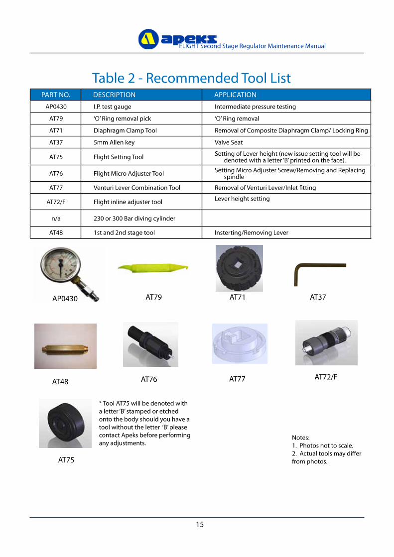
Table 2 - Recommended Tool ListPART NO. DESCRIPTION APPLICATION
AP0430 I.P. test gauge Intermediate pressure testing
AT79 ‘O’ Ring removal pick ‘O’ Ring removal
AT71 Diaphragm Clamp Tool Removal of Composite Diaphragm Clamp/ Locking Ring
AT37 5mm Allen key valve Seat
AT75 Flight Setting Tool Setting of Lever height (new issue setting tool will be-denoted with a letter ‘B’ printed on the face).
AT76 Flight Micro Adjuster Tool Setting Micro Adjuster Screw/Removing and Replacing spindle
AT77 venturi Lever Combination Tool Removal of venturi Lever/Inlet fitting
AT72/F Flight inline adjuster tool Lever height setting
n/a 230 or 300 Bar diving cylinder
AT48 1st and 2nd stage tool Insterting/Removing Lever
AP0430 AT79
Notes: 1. Photos not to scale.2. Actual tools may differ from photos.
AT37AT71
AT75
AT76 AT77 AT72/FAT48
* Tool AT75 will be denoted with a letter ‘B’ stamped or etched onto the body should you have a tool without the letter ‘B’ please contact Apeks before performing any adjustments.

16
FLIGHT Second Stage Regulator Maintenance Manual
Table 3 - Recommended Lubricants & Cleaners
LUBRICANT / CLEANER APPLICATION SOURCE
Christo-Lube® MCG-111 (Lubricant)
All ‘O’ Ring seals Apeks Marine Equipment LtdPN AP1495, or
Lubrication Technologies 310 Morton Street Jackson, OH 45640, USA (800) 477-8704
Biox(Cleaning agent)
Biological immersion fluid for reus-able stainless steel and brass parts.
Solent Divers Ltd122-128 Lake Rd, Portsmouth,Hants, PO1 4HH
White distilled vinegar (100 gr.)(Cleaning agent)
Acid bath for reusable stainless steel and brass parts.
“Household” grade
Liquid dishwashing detergent diluted with warm water(Cleaning agent)
Degreaser for brass and stainless steel parts; general cleaning solu-tion for plastic and rubber
“Household” grade
CAUTION: Silicone rubber requires no lubrication or preservative treatment. DO NOT apply grease or spray to silicone rubber parts (eg. Diaphragm, Exhaust valves.) Doing so may cause a chemical breakdown and premature deterioration of the material.
CAUTION: Do not use muriatic acid for the cleaning of any parts. Even if strongly diluted, muriatic acid can harm chrome plating and may leave a residue that is harmful to ‘O’ Ring seals and other parts

17
FLIGHT Second Stage Regulator Maintenance Manual
Cleaning & Lubrication ProcedureGeneral Cleaning of all Parts1. Place all components in an ultrasonic cleaning bath containing an appropriate cleaning solution, such as Biox.
2. All plastic and composite components such as the Inlet Fitting and Spindle must be cleaned in soapy water.
3. The components should be cleaned for 6 minutes, depending upon their condition. Longer cleaning times may used if required.
4. Rinse the components in warm fresh water.
5. The components should then be blown dry or left to dry naturally.
Lubrication and DressingAll ‘O’ Rings should be lubricated with Christo-Lube® MCG-111. Dress the ‘O’ Rings with a very light film of grease, and remove any visible excess by running the ‘O’ Ring between thumb and forefinger. Avoid applying excessive amounts of Christo-Lube grease, as this will attract particulate matter that may cause damage to the ‘O’ Ring.
Enriched Air Nitrox Use - Outside EEC (European Economic Community) Countries
your Apeks regulator has been prepared for use with Enriched Air Nitrox (EAN) where the percentage of oxygen in the EAN does not exceed 40%. This is possible
because each regulator is built to a high standard of cleanliness using EAN compatible components and lubricants. In addition, each regulator design has
passed stringent adiabatic compression testing to ensure its safety and compatibility with increased percentages of oxygen.
If it is your intention to use your new Apeks regulator with Nitrox EAN (O2 not to exceed 40%), it is imperative that you maintain the internal cleanliness of
the regulator (see section on Care and Maintenance). If it is your intention to use the regulator interchangeably with breathing air, the breathing air should be
oxygen-compatible or “hyperfiltered” where the condensed hydrocarbons do not exceed 0.1 mg/m3. your local authorised Apeks dealer can help you determine
whether the breathing air that they provide meets this criterion.
Standard compressed breathing air meeting the EN 12021 standard, often referred to as Grade E in the United States, does not necessarily meet this criterion.
Grade E or EN 12021 breathing air may contain a certain level of hydrocarbons, including traces of compressor oils that while not considered harmful to
breathe, can pose a risk in the presence of elevated oxygen content. Passing hydrocarbons through a valve and regulator creates a cumulative effect where the
hydrocarbons build up over time along the internal passageways of the equipment. When these hydrocarbons come into contact with
high-pressure oxygen enriched air, they can pose a very real hazard that can lead to combustion. Therefore, if a regulator has had use with Grade E or EN 12021 breathing air, it should be returned to an authorised Apeks dealer for overhaul service including oxygen cleaning, prior to being put back into nitrox service. Although second stage components are not exposed to high pressure EAN, Apeks recommends that the same cleaning procedures be followed for the complete regulator. This prevents the possibility of cross contamination and guarantees the cleanliness of the entire regulator.
Enriched Air Nitrox Use – Inside EEC (European Economic Community ) countries EN 1443-3 and EN13949
In CEE countries, diving with Nitrox/O2 is controlled by Standards EN 144-3 – Respiratory protective devices - Gas cylinder valves - Part 3: Outlet connections
for diving gases Nitrox and oxygen - and EN 13949 – Respiratory equipment - Open circuit self-contained diving apparatus for use with compressed Nitrox and
oxygen - requirements, testing, marking.
NOTE : Apeks offers a range of regulators designed and manufactured specially for use with oxygen-enriched mixtures, over 21% and up to 100% oxygen.
This range has been certified according to the EN 144-3 and EN 13949 standards and meets the requirements of the adiabatic compression tests. They have
received CE certification for this type. For further information on this range, contact your Apeks specialist centre.
WARNING : These regulators fitted with special connections should be used only with complementary equipment (tank valves, tanks, pressure gauges,
etc.) designed and prepared for use with an oxygen-enriched mixture. These items are marked Nitrox/O2.
WARNING: If the regulator that you use is fitted with a yoke or DIN connection, it is designed for use only with compressed breathing air (21% oxygen
and 79% nitrogen) which meets the EN 12021 standard. DO NOT USE this equipment with other mixtures or with gases containing more than 21% oxygen.
Disregarding this rule could result in serious injury or death caused by fire or explosion.
Every Nitrox/O2 regulator is assembled in a clean workshop, using compatible components and special lubricants. It is important to maintain the interior of the regulator in a clean state. Breathing air used in the production of a mixture should be oxygen compatible and double filtered with a hydrocarbon content not greater than 0.1 mg/m3.
WARNING: Please check the regulations regarding Nitrox in your particular country as this may differ from Apeks standard policy.

18
FLIGHT Second Stage Regulator Maintenance Manual
Table 5 - Test Bench Specifications
Table 4 - Torque Specifications
PART NUMBER DESCRIPTION / KEy NUMBER TORQUE
n/a n/a n/a
TEST CONDITION ACCEPTABLE RANGE
Opening EffortHigh Pressure > 50 bar gauge Medium pressure 9.5±0.5 bar
+1.4 to +1.6 in. H20 (3.5 to 4.0 mbar)
External LeakHigh Pressure > 50 bar gauge
Medium Pressure 9.5±0.5 barNo Leaks allowed
19
FLIGHT Second Stage Regulator Maintenance Manual
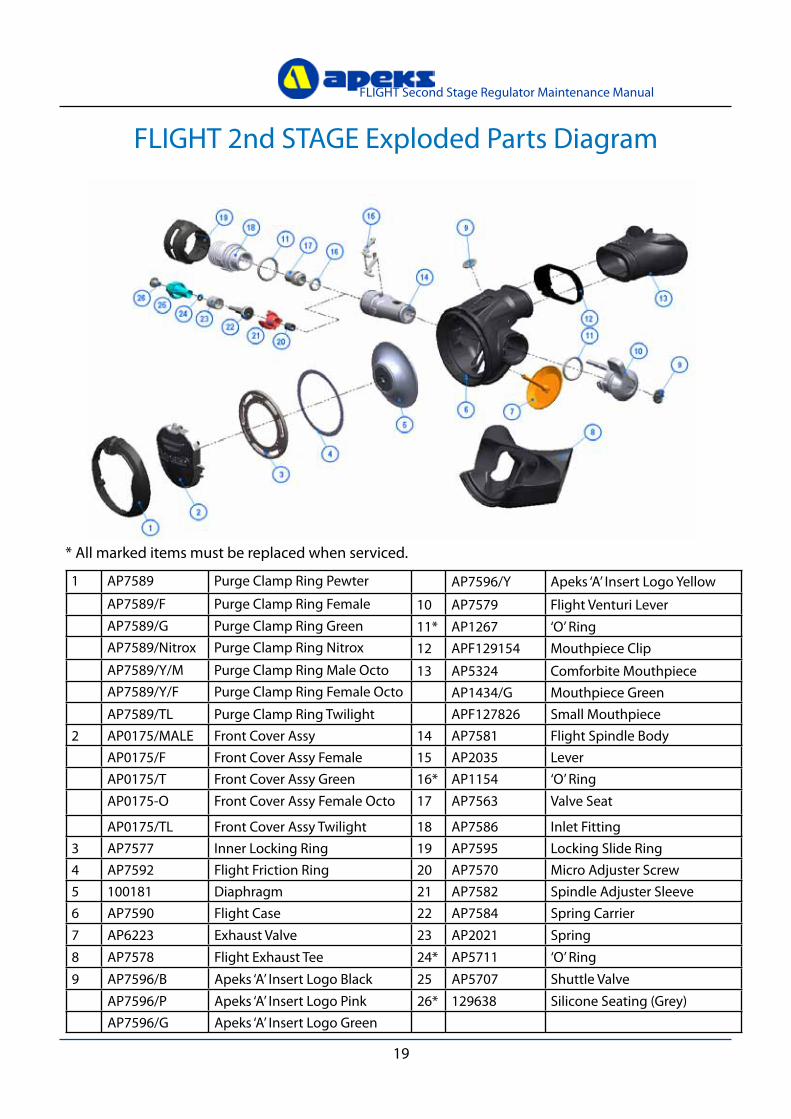
1 AP7589 Purge Clamp Ring Pewter AP7596/y Apeks ‘A’ Insert Logo yellow
AP7589/F Purge Clamp Ring Female 10 AP7579 Flight venturi LeverAP7589/G Purge Clamp Ring Green 11* AP1267 ‘O’ RingAP7589/Nitrox Purge Clamp Ring Nitrox 12 APF129154 Mouthpiece ClipAP7589/y/M Purge Clamp Ring Male Octo 13 AP5324 Comforbite MouthpieceAP7589/y/F Purge Clamp Ring Female Octo AP1434/G Mouthpiece GreenAP7589/TL Purge Clamp Ring Twilight APF127826 Small Mouthpiece
2 AP0175/MALE Front Cover Assy 14 AP7581 Flight Spindle BodyAP0175/F Front Cover Assy Female 15 AP2035 LeverAP0175/T Front Cover Assy Green 16* AP1154 ‘O’ RingAP0175-O Front Cover Assy Female Octo 17 AP7563 valve Seat
AP0175/TL Front Cover Assy Twilight 18 AP7586 Inlet Fitting3 AP7577 Inner Locking Ring 19 AP7595 Locking Slide Ring4 AP7592 Flight Friction Ring 20 AP7570 Micro Adjuster Screw5 100181 Diaphragm 21 AP7582 Spindle Adjuster Sleeve6 AP7590 Flight Case 22 AP7584 Spring Carrier7 AP6223 Exhaust valve 23 AP2021 Spring8 AP7578 Flight Exhaust Tee 24* AP5711 ‘O’ Ring9 AP7596/B Apeks ‘A’ Insert Logo Black 25 AP5707 Shuttle valve
AP7596/P Apeks ‘A’ Insert Logo Pink 26* 129638 Silicone Seating (Grey)AP7596/G Apeks ‘A’ Insert Logo Green
FLIGHT 2nd STAGE Exploded Parts Diagram
* All marked items must be replaced when serviced.

20
FLIGHT Second Stage Regulator Maintenance Manual

FLIGHT SECOND STAGE REGULATOR
AUTHORISED TECHNICIANS
Apeks Marine Equpment LtdNeptune Way, Blackburn, Lancs, England, BB1 2BT
MAINTENANCE MANUAL FOR
TECHNICAL SUPPORT