nmr reaction monitoring in flow synthesis - journals · in this regard, flow chemistry is the...
TRANSCRIPT

285
NMR reaction monitoring in flow synthesisM. Victoria Gomez and Antonio de la Hoz*
Review Open Access
Address:Área Química Orgánica, Facultad de Químicas, Universidad deCastilla-La Mancha, Avda. Camilo José Cela nº 10, E-13071 CiudadReal, Spain and Instituto Regional de Investigación CientíficaAplicada (IRICA), Avda. Camilo José Cela s/n, E-13071 Ciudad Real,Spain
Email:Antonio de la Hoz* - [email protected]
* Corresponding author
Keywords:expert systems; flow chemistry; microcoil; NMR probes
Beilstein J. Org. Chem. 2017, 13, 285–300.doi:10.3762/bjoc.13.31
Received: 28 November 2016Accepted: 03 February 2017Published: 14 February 2017
This article is part of the Thematic Series "Automated chemicalsynthesis".
Guest Editor: I. R. Baxendale
© 2017 Gomez and de la Hoz; licensee Beilstein-Institut.License and terms: see end of document.
AbstractRecent advances in the use of flow chemistry with in-line and on-line analysis by NMR are presented. The use of macro- and
microreactors, coupled with standard and custom made NMR probes involving microcoils, incorporated into high resolution and
benchtop NMR instruments is reviewed. Some recent selected applications have been collected, including synthetic applications,
the determination of the kinetic and thermodynamic parameters and reaction optimization, even in single experiments and on the μL
scale. Finally, software that allows automatic reaction monitoring and optimization is discussed.
285
IntroductionNew enabling technologies have facilitated the transition from
traditional chemistry to a more automated approach that will be
the chemistry of the 21st century [1,2]. The objective is that the
reaction, analysis and work-up can be performed in an auto-
matic and continuous manner, but optimization and scale-up
represent a new step forward towards the full automation of the
chemical process [3]. The final objective is to save time for
chemists to focus on the more technical work and to spend
their time planning, interpreting results and developing new
projects.
In this regard, flow chemistry is the central motif of this auto-
mated approach. In contrast to batch mode, in flow chemistry
the starting materials are continuously introduced into the flow
reactor (e.g., a microreactor or a column) and the product is
continuously eluted from the end of the flow reactor. This ap-
proach can be used from microscale to laboratory scale and
even to production scale [4,5].
Some important advantages of flow chemistry are:
• Diffusion is clearly improved with regard to chemistry in
batch (reagents and products), thus leading to improved
heat and mass transfer.
• The surface to volume ratio increases with regard to
reactions in batch. This enables good control of the reac-
tion temperature and resolves the problems of highly
exothermic reactions.
Beilstein J. Org. Chem. 2017, 13, 285–300.
286
• Dangerous or air- and moisture-sensitive compounds can
be used safely due to the small amounts of reagents and
the use of a closed system with efficient control of pres-
sure.
• The use of solvents can be minimized since concentra-
tions can be increased up to the limit of solubility.
• Coupling with other enabling technologies is very simple
and more efficient than in batch (photochemistry, elec-
trochemistry, microwave, ultrasound, etc.) [6-9].
In this regard, in a recent paper a compact reconfigurable flow
system was described for the continuous flow production of
pharmaceuticals. The system comprised different types of prep-
aration, reaction and elaboration modules that could be coupled
in different configurations and the authors used them to prepare
from hundreds to thousands of doses of pharmaceuticals that
fulfilled the quality standards of the pharmacopeia [10].
In research laboratories that focus on rapid, reproducible and
efficient analysis and optimization, and on the production scale
for quality control, the coupling of flow and microreactor tech-
nology with a good analytical method is a prerequisite. Several
analytical methods have been used and these include fluores-
cence, ultraviolet–visible (UV–vis), RAMAN, infrared (IR) and
nuclear magnetic resonance (NMR) spectroscopy and mass
spectrometry (MS). The use of a particular technique depends
on the application, on the characteristics of the analyte and the
ease of coupling with the flow system [11,12].
In this paper we focus on the coupling of nuclear magnetic reso-
nance spectroscopy with flow and microreactor systems for the
rapid analysis and optimization of reaction parameters and
conditions. The use of this technique in mechanistic studies is
also discussed.
ReviewCommercial flow probesNMR spectroscopy is based on the absorption of radiofre-
quency radiation to produce absorption on the nuclear spin level
when nuclei are submitted to a strong magnetic field [13]. NMR
spectroscopy is one of the most powerful and versatile methods
for structural determination, enabling qualitative and quantita-
tive analysis of samples. It can be applied to almost all ele-
ments in the periodic table, the only requirement being the pres-
ence of an isotope, not necessarily the most abundant, that
shows magnetic properties.
The main drawback of NMR spectroscopy is that the sensitivity
is very low when compared with other spectroscopic tech-
niques such as UV, since the difference in population between
the ground and the excited state is very low and is strongly de-
pendent on the permanent magnetic field (B0) applied. This lim-
itation is compensated by using stronger magnetic fields, which
results in more complex, large and expensive NMR instruments
and/or the development of specialized probes. Although the low
sensitivity of NMR spectroscopy is a disadvantage for an ana-
lytical method, the power of this technique in structural deter-
mination compensates for its limitations.
The application of NMR spectroscopy to analytical chemistry in
flow, preparative flow chemistry and microreactor technology
requires the use of specially designed equipment, especially
flow probes, flow cells or specialized microfluidic coils. In
most cases, high-resolution NMR instruments are used but the
high cost of these systems and the large space required limit
their application on the laboratory scale and lab-on-a-chip.
Recently, benchtop low field NMR instruments have been intro-
duced in flow chemistry to overcome these limitations, with the
advantage of lower cost and better integration with the continu-
ous flow platform since the whole system can be set up in a
fume hood. The main drawback of these systems is the lower
resolution and sensitivity as compared to high resolution NMR
instruments, which limits the application of benchtop NMR
instruments to relatively simple structures.
Two classes of flow probes have been designed depending on
the position of the sample tube, which can be vertical (denoted
below as type 1) or horizontal (denoted below as type 2)
(Figure 1), and the shape of the RF coil for transmitting and
receiving, namely saddle-shaped when the sample tube is
placed vertically and solenoidal when the sample tube is placed
horizontally [14]. Manufacturers have designed commercial
NMR flow probes of type 1 that can be integrated into their
high and low-resolution NMR instruments. Type 2 probes have
been designed by different research groups and integrated into
standard NMR instruments.
Flow probes can further be classified as ‘room temperature
probes’ if the RF coils and the sample are at similar tempera-
tures or as ‘cryogenic probes’ if the RF coils are insulated from
the sample chamber and kept cold.
The development of commercial NMR flow probes requires a
different design when compared to the standard tube-based
probes. For the design of a NMR flow probe, similarly to the
design of a new probe head, careful choice of the components
should be made in order to have an optimal resolution, sensi-
tivity and RF homogeneity, but in addition, other factors should
be taken into account because of working on-flow. Hence, the
design should allow a high filling factor, the flash out of air
bubbles and the displacement of the existing fluid in the detec-
tion volume by the incoming fluid instead of just mix with it,

Beilstein J. Org. Chem. 2017, 13, 285–300.
287
Figure 1: Graphical representation of (a) conventional flow cell with asaddle-shaped RF coil and (b) flow capillary with a solenoid coil.
among other issues [14]. Hence, the flow cell is a sample tube
(made of glass or quartz) with openings at the top (outlet) and at
the bottom (inlet) to enable connection to the flow system.
NMR flow cells generally have a larger inner diameter at the
centre than at the ends (Figure 1). The larger central portion of
the flow cell is the sample chamber, i.e., the detection zone. The
smaller segments at the ends correspond to the inlet and the
outlet stems. When designing a flow cell, the total volume of
the sample chamber is considered to be the minimum volume
and this must be twice the active volume. This ratio is similar to
that found for 5 mm NMR tubes in standard probes.
Flow cells are usually made of quartz, although Pyrex®,
sapphire and alumina can also be considered. Quartz is the ma-
terial of choice because of its uniformity, purity and mechani-
cal strength. Moreover, quartz is a machinable material and
shows excellent electrical properties. Tubing connections are
made of PEEK (poly-ether-ketone) due to the strength of this
material. However, PEEK has three main drawbacks, it absorbs
DMSO and CH3OH, it is not compatible with acids and it does
not have a good turn radius.
Finally, most standard flow probes include pulsed-field gradient
hardware, which enables interesting uses for the probe such as
gradient shimming, solvent suppression pulse sequences (i.e.,
WET, which is especially suitable for applications in flow), and
the use of pulse sequences that incorporate gradients, nowadays
commonly found within most NMR experiments.
Considering the points outlined above, several advantages of
flow NMR over traditional NMR can be envisaged. Firstly, ad-
ditional time is not required to lock or shim each sample when
the solvent is kept constant during the experiment. Secondly,
deuterated solvents are not required because of WET
solvent suppression and also because locking is not required.
Thirdly, more samples can be analyzed automatically from
microtiter plates, thus avoiding the use and possible breakage of
glass sample tubes.
Microcoil probesAn interesting way to increase the sensitivity of NMR is the use
of microcoil probes [15,16]. Based on the reciprocity principle
[15], it has been shown that for a constant length-to-diameter
ratio, the NMR detector (i.e., coil) sensitivity is inversely
proportional to its diameter. For a volume-limited sample, the
signal is maximized when the coil is scale-down to enclose this
volume sample. Although these probes show several advan-
tages, as for instance are the coupling into continuous flow
systems and its integration in compact magnets due to their
lower requirements for the spatial B0 field homogeneity, the
construction of the probe for the highest sensitivity and resolu-
tion is a challenging task. The latter falls outside the scope of
this review and instead, we will describe the types and features
of microcoil probes in this section and its integration with flow
systems in the following sections.
An important requirement in NMR spectroscopy is that a suffi-
ciently strong B1 is generated perpendicular to the static
Bo field. The geometry of the coil is very important in order to
generate a homogeneous B1 field over the entire sample
volume. Hence, the geometry of the coil should be optimized in
order to obtain the highest possible sensitivity and resolution.
The most widely used geometries for NMR coils are repre-
sented in Figure 2. The most typical geometry used in commer-
cial solution NMR probes is the saddle type. Although this ge-
ometry generates a very homogeneous magnetic field orthogo-
nal to the permanent field B0, it is not suitable for miniaturiza-
tion. As a consequence, the saddle coil it is not used in small-
volume NMR applications.
The main geometries reported for microcoils are, solenoidal,
flat helical (also called planar microcoils), microslot and
stripline (Figure 2). Below, the planar and solenoid coils are
discussed more in detail as they are the most reported in litera-
ture.
Microsolenoid coilsA coil of helical geometry is wrapped around a capillary
adopting the size and shape of the sample and therefore, a good
filling factor is achieved. Solenoid coils have been investigated
in detail. A representative example was reported by Sweedler et
al. [17] who designed a microsolenoid coil with a detection cell

Beilstein J. Org. Chem. 2017, 13, 285–300.
288
Figure 2: Possible geometries of NMR coils.
volume of ca. 5 nL, and line widths of only 0.6 Hz for a neat
ethylbenzene sample. Recently, a new manufacturing proce-
dure, by using a sacrificial layer and a combination of solvents,
has been reported by Gruschke et al. [18] yielding a maximized
and optimum filling factor compared to former procedures as
hollow microcoils are encased in external support structures. A
new methodology for the easy fabrication of solenoid coils has
been reported by Saggiomo and Velders [19] using 3D-printing
technology. The authors described an easy two-step ABS
(acrylonitrile butadiene styrene) scaffold removal method to
obtain a 3D printed device inserted in a block of PDMS (polydi-
methylsiloxane). The authors tested this methodology for the
creation of microfluidic devices but they also fabricated a
simple, cheap and sensitive NMR microsolenoid [19] with a
detection volume of only 2 μL. Integration with a 9.4 T super-
conducting magnet allowed them to obtain high-resolution
NMR spectra.
The main advantages of microsolenoid coils are: Excellent
B1-field uniformity and B1/i field efficiency resulting in a high
signal-to-noise ratio (SNR). In comparison to planar coils, the
solenoid have lower resistance, better nutation curves (reaching
the ideal sinusoidal behaviour) representing a much more
uniform B1 field than planar coils, however solenoid coils show
lower resolution than planar coils in a comparative study re-
ported by Popovic et al. [20] when both types of coils were
fabricated following the same process.
And the main disadvantages of microsolenoid coils: Tedious
manufacturing procedure especially for very small volumes as
well as encountering the optimum position of the sample in the
coil. Solenoid coils are usually wound by hand, resulting in a
low reproducible and very time-consuming process.
Planar coilsSpiral planar coils were introduced in NMR spectroscopy
derived from the semi-conductor industry by means of micro-
fabrication techniques. Planar coils were studied in detail by
Popovic et al. [21] as an alternative to solenoid coils. Planar
coils show the following advantages:
They can be batch-fabricated with submicrometer resolution
and with a high degree of geometric precision and repro-
ducibility by standard photolithographic techniques. In addition,
they can be integrated with chip-based microfluidic systems. To
end with the advantages, planar coil facilitate an increased
throughput since an array of planar coils and microfluidic chan-
nels can be manufactured by microfabrication techniques
[15,16,21].
The disadvantages of planar coils are: Planar coils suffer of a
high series resistance resulting in a low SNR as the latter is
dominated by the thermal noise of the coil. The SNR depends
on the geometrical features of the coil. For instance, the num-
ber of turns is crucial since a large number of turns can increase
the unitary field produced by the coil but will also lead to higher
resistance [21]. It is believed that the nearby windings of the
coil induce static field distortions resulting in lower resolution
and sensitivity in the NMR spectrum [22]. The optimum dimen-
sions for a planar microcoil were presented by van den Berg et
al. [23] and obtained from finite-element simulations [24]. High
SNR were obtained at a low-field magnet. Another disadvan-
tage of planar coils is the weak and inhomogenous B1-field pro-
duced by the coil resulting in a non-sinusoidal nutation curve
and in low SNR of the free induction decay [20].
Despite these disadvantages, interesting applications of planar
microcoils can be found in literature. Hence, Velders et al. [25]
studied supramolecular interactions by 19F NMR spectroscopy
at the picomole level. This application takes advantage of the
high sensitivity and large chemical-shift dispersion of this
nucleus. The authors determined the association constant of the
complex of NaPF6 with α-cyclodextrin at the picomole level
with a detection volume of 50 nL and using non-deuterated sol-
vents [25].
To conclude with the different coil geometries, microslot NMR
microprobes and stripline coils show also interesting applica-
tions in small-volume NMR spectroscopy. A microslot consists
of a dual-layer metallic microstrip that can have submicrometer
dimensions. These coils produce field lines that are more homo-
Beilstein J. Org. Chem. 2017, 13, 285–300.
289
geneous than those obtained with planar coils or just a metallic
wire and find applications even for NMR metabolomics [26].
Stripline coils represent a simple and effective coil design with
interesting applications even as detectors in DNP methods
[22,27]. Stripline coils produce high and homogeneous B1 field,
can be integrated on a microfluidic chip and show scalability as
reported by Kentgens et al. [22].
Applications of flow NMR in reactionmonitoringKeifer defined flow-NMR [28] as any NMR technique in which
the sample flows through a tube into the NMR probe at some
time during the measurement process.
The first reported use of a flow-NMR technique was in 1951
[29], when the 1H spectrum of water (doped with FeCl3) was
recorded as it flowed through the NMR probe. In the seventies,
a group of related techniques that were variously called
‘stopped-flow NMR’ [30], ‘rapid-injection NMR’ [31], ‘contin-
uous-flow’ NMR [32], or just ‘flow NMR’ [33] were intro-
duced and their use has continued to the present day. All of
these techniques involve the use of standard NMR probes and
do not require specialized equipment.
The introduction of LC–NMR was a natural development, al-
though LC–NMR requires the use of an NMR probe that is
dedicated solely to the observation of a sample flowing through
tubing from another source. This requirement led to the investi-
gation, design and development of the NMR flow probe.
Several techniques were developed for the integration of the
two systems, such as on-flow and stopped-flow LC–NMR. In
the on-flow technique the solvent stream flows continuously
during the analysis. However, one important problem that must
be addressed is to achieve a good NMR signal-to-noise ratio.
This limitation is more important than the chromatographic
resolution. The NMR signal-to-noise ratio can be improved by
signal averaging, but this approach usually requires the flow to
be stopped for substantial periods of time.
The terms in-line and on-line analysis have been commonly
used. ‘In-line’ and ‘on-line’ refer to methods of analysis that do
not require the manual transfer of samples [34]. When the NMR
probe and the reaction system are connected in-series, all of the
reaction mixture passes through the NMR instrument and is
continuously analyzed. This method is called in-line analysis.
This configuration minimises the time-lag between reaction and
analysis. For on-line analysis the NMR system is not directly
connected to the reaction system and the sample is transferred
from the reaction to the analysis system with representative
aliquots collected periodically during the reaction. This method
is simpler and can be used when direct connection is difficult to
be analyzed by NMR. A similar definition is provided by the
FDA: “on-line: Measurement where the sample is diverted from
the manufacturing process, and may be returned to the process
stream. In-line: Measurement where the sample is not removed
from the process stream and can be invasive or non-invasive”
[35].
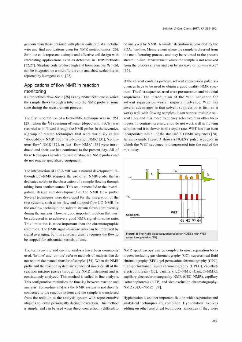
If the solvent contains protons, solvent suppression pulse se-
quences have to be used to obtain a good quality NMR spec-
trum. The first sequences used were presaturation and binomial
sequences. The introduction of the WET sequence for
solvent suppression was an important advance. WET has
several advantages in that solvent suppression is fast, so it
works well with flowing samples, it can supress multiple sol-
vent lines and it is more frequency selective than other tech-
niques. In contrast, pre-saturation do not work well in flowing
samples and it is slower in its recycle rate. WET has also been
incorporated into all of the standard 2D NMR sequences [28].
As an example Figure 3 shows a NOESY pulse sequence in
which the WET sequence is incorporated into the end of the
mix delay.
Figure 3: The NMR pulse sequence used for NOESY with WETsolvent suppression [28].
NMR spectroscopy can be coupled to most separation tech-
niques, including gas chromatography (GC), supercritical fluid
chromatography (SFC), gel-permeation chromatography (GPC),
high-performance liquid chromatography (HPLC), capillary
electrophoresis (CE), capillary LC–NMR (CapLC–NMR),
capillary electrochromatography-NMR (CEC–NMR), capillary
isotachophoresis (cITP) and size-exclusion chromatography-
NMR (SEC–NMR) [28].
Hyphenation is another important field in which separation and
analytical techniques are combined. Hyphenation involves
adding on other analytical techniques, almost as if they were

Beilstein J. Org. Chem. 2017, 13, 285–300.
290
Figure 4: Reaction of p-phenylenediamine with isobutyraldehyde. (a) Flow tube and (b) 1H NMR stacked plot (400 MHz). NMR signals used tomonitor the reaction (245 spectra were recorded in 47 h). Reproduced with permission from reference [39]. Copyright 2014 The American ChemicalSociety.
‘building blocks’, for instance, LC–NMR–MS, which was first
described in 1995.
Flow Injection Analysis-NMR (FIA–NMR) and Direct Injec-
tion-NMR (DI–NMR) were the first non-chromatographic flow-
NMR methodologies to be introduced. By simply removing the
chromatography column LC–NMR produces FIA–NMR, a
technique that has the capability of performing multiple
analyses rapidly.
In contrast to FIA–NMR, DI–NMR lacks a mobile phase, just
the solvent to dissolve the sample and some additional to rinse
the flow cell. Also, the pump is simplified and the sample is
injected directly into the flow probe to give a simple flow-NMR
system. Applications of DI–NMR include combinatorial chem-
istry for the analysis of libraries [36], analysis of biofluids for
clinical diagnosis [37] and metabolomics [38].
Applications in organic synthesisIn this section we will discuss some recent selected examples of
the application of NMR reaction monitoring in flow chemistry.
These examples include the design of flow systems, the use of
standard NMR instruments and flow probes, the use of micro-
coils and finally the use of flow-NMR for kinetic and mechanis-
tic studies and for the optimization of synthetic processes.
Marquez et al. [39] developed a new NMR flow tube for the use
in a standard 5 mm NMR probe (Figure 4). This system allows
experiments to be carried out on flowing samples. The authors
tested this flow tube to monitor the standard reaction of
p-phenylenediamine and isobutyraldehyde to form the diimine
product and good results and reproducibility were obtained.
The authors consider that this technology can be used to deter-
mine the mechanistic and kinetic aspects of reactions without a
specialized flow probe and using different kinds of spectrome-
ters with varying magnetic field strengths.
Danielli et al. [40] described the application of Benchtop NMR
spectroscopy in flow reactions (SpinSolve from Magritek at
60 MHz). They considered that the field homogeneity and
sensitivity that compact NMR spectrometers provide is suffi-
cient to analyze small molecules at concentrations of
1 mmol L−1 in single-scan experiments. As a proof-of-concept,

Beilstein J. Org. Chem. 2017, 13, 285–300.
291
Figure 5: Scheme and experimental setup of the flow system.
they studied the transfer hydrogenation process of aceto-
phenone with isopropanol catalysed by iridium complexes. The
reaction was performed in batch and the sample was introduced
into the magnet with a pump and Teflon tubing to form a closed
circuit, at a flow rate of 1 mL min−1. The kinetic rate could be
studied as a function of the catalyst concentration and good
agreement was found with the results obtained by gas chroma-
tography. As expected for a first-order reaction, a linear depen-
dence of the kinetic constant on the catalyst concentration was
found.
An interesting point to consider is the comparison of in-line and
off-line analysis. For example, Duchateau et al. [41] described
the preparation of Grignard reagents from aryl halides and
magnesium using a fluidized bed reactor under continuous-flow
conditions. In a second flow reactor the Grignard was reacted
with CO2 to obtain carboxylic acids (Figure 5). The whole
process was monitored by on-line 1H NMR spectroscopy using
a low field NMR instrument (Spinsolve-60 from Magritek).
The reaction was analysed by in-line NMR and off-line with a
standard NMR tube. In the first case, the amount of oxidized
Grignard reagent was significantly lower, showing the advan-
tages of in-line measurements. In the in-line experiment
the reaction mixture was introduced into the flow NMR
cell at 1 mL min−1 showing a conversion of about 80% in
70 min.
In this regard, Foley et al. [42] reported a comparison of three
different methods for the analysis of flow reactions: online
NMR, static NMR tubes, and periodic inversion of NMR tubes,
using a high-resolution NMR instrument (400 MHz). Both
studied reactions, heterogeneous reactions with long reaction
times and homogeneous reactions with short reaction times
showed that mixing has an important effect on the final result.
A careful evaluation of the three analytical methods and reac-
tion conditions showed that the NMR technique has a signifi-
cant influence on the results of the analysis. Considering the ap-
plication of interest, the choice of one or other method could be
crucial. In this regard, flow NMR gives more accurate results
for kinetic studies, while static NMR is suitable to obtain struc-
tural information and determination of the mechanism.
The NMR instrument should also be evaluated considering that
high-resolution NMR instruments are expensive, in terms of
Beilstein J. Org. Chem. 2017, 13, 285–300.
292
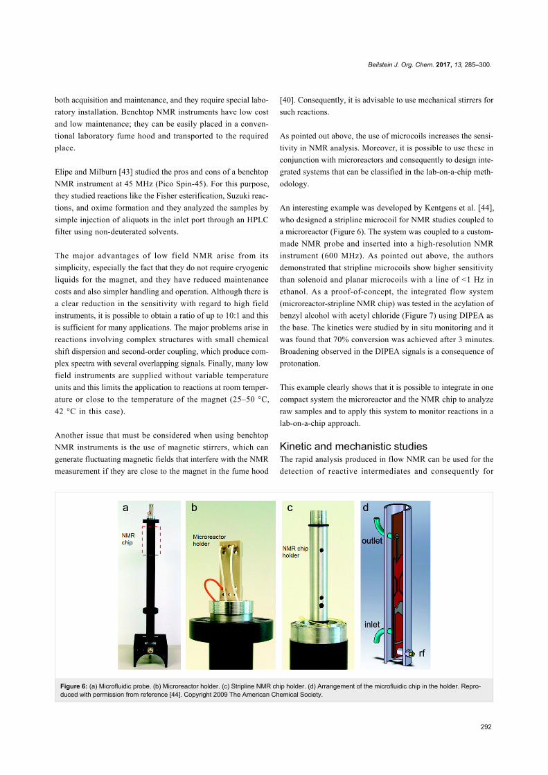
Figure 6: (a) Microfluidic probe. (b) Microreactor holder. (c) Stripline NMR chip holder. (d) Arrangement of the microfluidic chip in the holder. Repro-duced with permission from reference [44]. Copyright 2009 The American Chemical Society.
both acquisition and maintenance, and they require special labo-
ratory installation. Benchtop NMR instruments have low cost
and low maintenance; they can be easily placed in a conven-
tional laboratory fume hood and transported to the required
place.
Elipe and Milburn [43] studied the pros and cons of a benchtop
NMR instrument at 45 MHz (Pico Spin-45). For this purpose,
they studied reactions like the Fisher esterification, Suzuki reac-
tions, and oxime formation and they analyzed the samples by
simple injection of aliquots in the inlet port through an HPLC
filter using non-deuterated solvents.
The major advantages of low field NMR arise from its
simplicity, especially the fact that they do not require cryogenic
liquids for the magnet, and they have reduced maintenance
costs and also simpler handling and operation. Although there is
a clear reduction in the sensitivity with regard to high field
instruments, it is possible to obtain a ratio of up to 10:1 and this
is sufficient for many applications. The major problems arise in
reactions involving complex structures with small chemical
shift dispersion and second-order coupling, which produce com-
plex spectra with several overlapping signals. Finally, many low
field instruments are supplied without variable temperature
units and this limits the application to reactions at room temper-
ature or close to the temperature of the magnet (25–50 °C,
42 °C in this case).
Another issue that must be considered when using benchtop
NMR instruments is the use of magnetic stirrers, which can
generate fluctuating magnetic fields that interfere with the NMR
measurement if they are close to the magnet in the fume hood
[40]. Consequently, it is advisable to use mechanical stirrers for
such reactions.
As pointed out above, the use of microcoils increases the sensi-
tivity in NMR analysis. Moreover, it is possible to use these in
conjunction with microreactors and consequently to design inte-
grated systems that can be classified in the lab-on-a-chip meth-
odology.
An interesting example was developed by Kentgens et al. [44],
who designed a stripline microcoil for NMR studies coupled to
a microreactor (Figure 6). The system was coupled to a custom-
made NMR probe and inserted into a high-resolution NMR
instrument (600 MHz). As pointed out above, the authors
demonstrated that stripline microcoils show higher sensitivity
than solenoid and planar microcoils with a line of <1 Hz in
ethanol. As a proof-of-concept, the integrated flow system
(microreactor-stripline NMR chip) was tested in the acylation of
benzyl alcohol with acetyl chloride (Figure 7) using DIPEA as
the base. The kinetics were studied by in situ monitoring and it
was found that 70% conversion was achieved after 3 minutes.
Broadening observed in the DIPEA signals is a consequence of
protonation.
This example clearly shows that it is possible to integrate in one
compact system the microreactor and the NMR chip to analyze
raw samples and to apply this system to monitor reactions in a
lab-on-a-chip approach.
Kinetic and mechanistic studiesThe rapid analysis produced in flow NMR can be used for the
detection of reactive intermediates and consequently for
Beilstein J. Org. Chem. 2017, 13, 285–300.
293
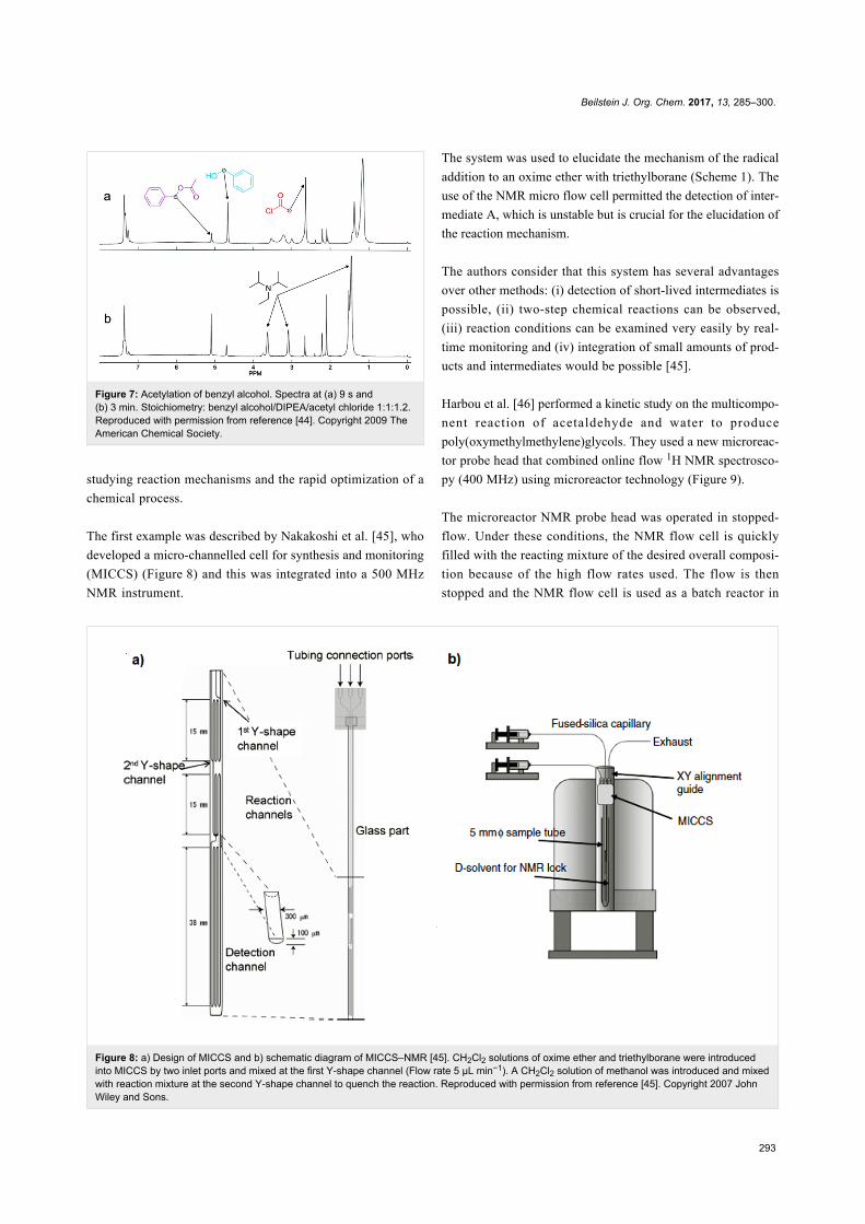
Figure 8: a) Design of MICCS and b) schematic diagram of MICCS–NMR [45]. CH2Cl2 solutions of oxime ether and triethylborane were introducedinto MICCS by two inlet ports and mixed at the first Y-shape channel (Flow rate 5 μL min−1). A CH2Cl2 solution of methanol was introduced and mixedwith reaction mixture at the second Y-shape channel to quench the reaction. Reproduced with permission from reference [45]. Copyright 2007 JohnWiley and Sons.
Figure 7: Acetylation of benzyl alcohol. Spectra at (a) 9 s and(b) 3 min. Stoichiometry: benzyl alcohol/DIPEA/acetyl chloride 1:1:1.2.Reproduced with permission from reference [44]. Copyright 2009 TheAmerican Chemical Society.
studying reaction mechanisms and the rapid optimization of a
chemical process.
The first example was described by Nakakoshi et al. [45], who
developed a micro-channelled cell for synthesis and monitoring
(MICCS) (Figure 8) and this was integrated into a 500 MHz
NMR instrument.
The system was used to elucidate the mechanism of the radical
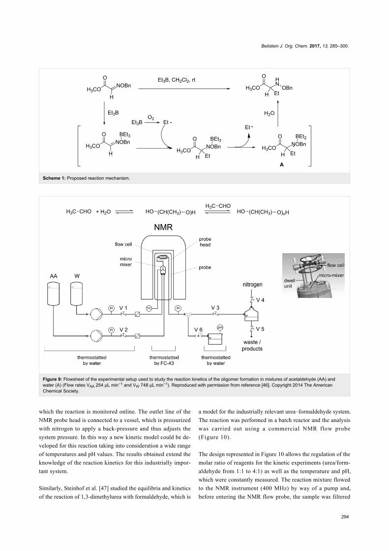
addition to an oxime ether with triethylborane (Scheme 1). The
use of the NMR micro flow cell permitted the detection of inter-
mediate A, which is unstable but is crucial for the elucidation of
the reaction mechanism.
The authors consider that this system has several advantages
over other methods: (i) detection of short-lived intermediates is
possible, (ii) two-step chemical reactions can be observed,
(iii) reaction conditions can be examined very easily by real-
time monitoring and (iv) integration of small amounts of prod-
ucts and intermediates would be possible [45].
Harbou et al. [46] performed a kinetic study on the multicompo-
nent reaction of acetaldehyde and water to produce
poly(oxymethylmethylene)glycols. They used a new microreac-
tor probe head that combined online flow 1H NMR spectrosco-
py (400 MHz) using microreactor technology (Figure 9).
The microreactor NMR probe head was operated in stopped-
flow. Under these conditions, the NMR flow cell is quickly
filled with the reacting mixture of the desired overall composi-
tion because of the high flow rates used. The flow is then
stopped and the NMR flow cell is used as a batch reactor in
Beilstein J. Org. Chem. 2017, 13, 285–300.
294
Scheme 1: Proposed reaction mechanism.
Figure 9: Flowsheet of the experimental setup used to study the reaction kinetics of the oligomer formation in mixtures of acetaldehyde (AA) andwater (A) (Flow rates VAA 254 μL min−1 and VW 748 μL min−1). Reproduced with permission from reference [46]. Copyright 2014 The AmericanChemical Society.
which the reaction is monitored online. The outlet line of the
NMR probe head is connected to a vessel, which is pressurized
with nitrogen to apply a back-pressure and thus adjusts the
system pressure. In this way a new kinetic model could be de-
veloped for this reaction taking into consideration a wide range
of temperatures and pH values. The results obtained extend the
knowledge of the reaction kinetics for this industrially impor-
tant system.
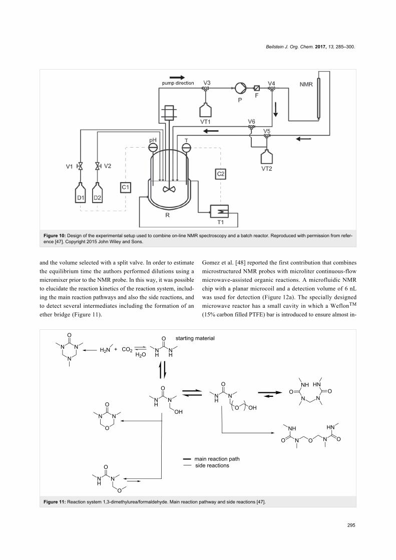
Similarly, Steinhof et al. [47] studied the equilibria and kinetics
of the reaction of 1,3-dimethylurea with formaldehyde, which is
a model for the industrially relevant urea–formaldehyde system.
The reaction was performed in a batch reactor and the analysis
was carried out using a commercial NMR flow probe
(Figure 10).
The design represented in Figure 10 allows the regulation of the
molar ratio of reagents for the kinetic experiments (urea/form-
aldehyde from 1:1 to 4:1) as well as the temperature and pH,
which were constantly measured. The reaction mixture flowed
to the NMR instrument (400 MHz) by way of a pump and,
before entering the NMR flow probe, the sample was filtered
Beilstein J. Org. Chem. 2017, 13, 285–300.
295
Figure 10: Design of the experimental setup used to combine on-line NMR spectroscopy and a batch reactor. Reproduced with permission from refer-ence [47]. Copyright 2015 John Wiley and Sons.
Figure 11: Reaction system 1,3-dimethylurea/formaldehyde. Main reaction pathway and side reactions [47].
and the volume selected with a split valve. In order to estimate
the equilibrium time the authors performed dilutions using a
micromixer prior to the NMR probe. In this way, it was possible
to elucidate the reaction kinetics of the reaction system, includ-
ing the main reaction pathways and also the side reactions, and
to detect several intermediates including the formation of an
ether bridge (Figure 11).
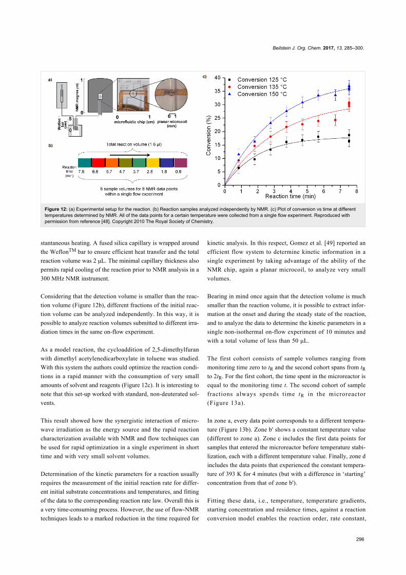
Gomez et al. [48] reported the first contribution that combines
microstructured NMR probes with microliter continuous-flow
microwave-assisted organic reactions. A microfluidic NMR
chip with a planar microcoil and a detection volume of 6 nL
was used for detection (Figure 12a). The specially designed
microwave reactor has a small cavity in which a WeflonTM
(15% carbon filled PTFE) bar is introduced to ensure almost in-
Beilstein J. Org. Chem. 2017, 13, 285–300.
296
Figure 12: (a) Experimental setup for the reaction. (b) Reaction samples analyzed independently by NMR. (c) Plot of conversion vs time at differenttemperatures determined by NMR. All of the data points for a certain temperature were collected from a single flow experiment. Reproduced withpermission from reference [48]. Copyright 2010 The Royal Society of Chemistry.
stantaneous heating. A fused silica capillary is wrapped around
the WeflonTM bar to ensure efficient heat transfer and the total
reaction volume was 2 μL. The minimal capillary thickness also
permits rapid cooling of the reaction prior to NMR analysis in a
300 MHz NMR instrument.
Considering that the detection volume is smaller than the reac-
tion volume (Figure 12b), different fractions of the initial reac-
tion volume can be analyzed independently. In this way, it is
possible to analyze reaction volumes submitted to different irra-
diation times in the same on-flow experiment.
As a model reaction, the cycloaddition of 2,5-dimethylfuran
with dimethyl acetylenedicarboxylate in toluene was studied.
With this system the authors could optimize the reaction condi-
tions in a rapid manner with the consumption of very small
amounts of solvent and reagents (Figure 12c). It is interesting to
note that this set-up worked with standard, non-deuterated sol-
vents.
This result showed how the synergistic interaction of micro-
wave irradiation as the energy source and the rapid reaction
characterization available with NMR and flow techniques can
be used for rapid optimization in a single experiment in short
time and with very small solvent volumes.
Determination of the kinetic parameters for a reaction usually
requires the measurement of the initial reaction rate for differ-
ent initial substrate concentrations and temperatures, and fitting
of the data to the corresponding reaction rate law. Overall this is
a very time-consuming process. However, the use of flow-NMR
techniques leads to a marked reduction in the time required for
kinetic analysis. In this respect, Gomez et al. [49] reported an
efficient flow system to determine kinetic information in a
single experiment by taking advantage of the ability of the
NMR chip, again a planar microcoil, to analyze very small
volumes.
Bearing in mind once again that the detection volume is much
smaller than the reaction volume, it is possible to extract infor-
mation at the onset and during the steady state of the reaction,
and to analyze the data to determine the kinetic parameters in a
single non-isothermal on-flow experiment of 10 minutes and
with a total volume of less than 50 μL.
The first cohort consists of sample volumes ranging from
monitoring time zero to tR and the second cohort spans from tR
to 2tR. For the first cohort, the time spent in the microreactor is
equal to the monitoring time t. The second cohort of sample
fractions always spends time tR in the microreactor
(Figure 13a).
In zone a, every data point corresponds to a different tempera-
ture (Figure 13b). Zone b' shows a constant temperature value
(different to zone a). Zone c includes the first data points for
samples that entered the microreactor before temperature stabi-
lization, each with a different temperature value. Finally, zone d
includes the data points that experienced the constant tempera-
ture of 393 K for 4 minutes (but with a difference in ‘starting’
concentration from that of zone b').
Fitting these data, i.e., temperature, temperature gradients,
starting concentration and residence times, against a reaction
conversion model enables the reaction order, rate constant,

Beilstein J. Org. Chem. 2017, 13, 285–300.
297
Figure 13: (a) Schematics of two microreactor cohorts of sample fractions. (b) Reaction product concentration (M) versus monitoring time (s) for thesynthesis of 5-methyl-3-phenylisoxazole in methanol at an overall flow rate of 5 μL/min (initial concentration, 0.35 M). Every data point corresponds toa 2.5 μL fraction. (c) Table with differences between the zones (a + b, b', c, d) in residence time, temperature, and concentration. Flow-NMR analysiswere performed in a 400 MHz instrument. Reproduced with permission from reference [49]. Copyright 2015 The American Chemical Society.
Arrhenius parameters, pre-exponential factor, and activation
energy values to be determined in a rapid manner from one
single flow experiment.
The two latter examples reported by Gomez et al. [48,49] illus-
trate the advantages of combining microprobes with flow tech-
niques. The capabilities of the microcoil of analysing very small
sample volumes enable the division of the reactor volume in
different portions of different experimental conditions, allowing
a fast collection of experimental data and therefore, a fast opti-
mization of reaction conditions and determination of kinetic pa-
rameters. On the other hand, some limitations and problems are
encountered when combining microcoils with flow techniques.
The usual limitations of working on flow NMR (i.e., clogging,
bubbles, precipitation and dirty flow cells among others) are
present at this small scale [28].
Finally, Cronin et al. [50] described a synthetic platform that in-
corporates a flow reactor, an in-line benchtop NMR instrument
(Spinsolve from Magritek) to monitor the organic reactions, and
a control system to analyze NMR (via Labview software) data
and optimize the reaction conditions. They performed a range of
reactions including imine formation (Figure 14), electrophilic
fluorinations and Diels–Alder reactions. This system was em-
ployed to perform kinetic studies, in-line structural characteriza-
tion including DEPT spectra, 2D-NMR spectroscopy, 19F NMR
spectroscopy and monitoring of the stereoselectivity in
Diels–Alder reactions and self-optimization of flow conditions
using a modified version of the Nelder–Mead algorithm. For the
NMR integral data for each experiment, the algorithm
(Figure 15) selects the composition and residence time for each
experiment.
Figure 14: NMR analysis of the reaction of benzaldehyde (2 M inCH3CN) and benzylamine (2 M in CH3CN) (1:1), residence time,30 min. Reproduced with permission from reference [50]. Copyright2015 The Royal Society of Chemistry.
This study showed the potential of the combined use of flow-
chemistry, real-time on-line analysis, especially by flow-NMR,
and design of experiments (DOE) for the characterization and
self-optimization of chemical reactions.

Beilstein J. Org. Chem. 2017, 13, 285–300.
298
Figure 15: Flow diagram showing the self-optimizing reactor system.Reproduced with permission from reference [50]. Copyright 2015 TheRoyal Society of Chemistry.
ConclusionReal-time analysis of a reaction is one of the key principles of
green chemistry [51] for pollution prevention. However, on-line
and in-line analysis together with the use of flow chemistry and
the appropriate software for analysis, determination of the
kinetic and thermodynamic parameters and for process optimi-
zation, are a key for a new type of chemistry in the 21st century.
In this regard, the use of NMR spectroscopy is probably the
most interesting technique of choice. Although NMR spectros-
copy lacks the high sensitivity of other analytical techniques
such as MS, IR, and UV–vis, it is possibly the most powerful
method for structural determination and it provides an excellent
platform for analysis and characterization of the reaction prod-
uct.
Besides the low sensitivity of flow NMR spectroscopy some
other limitations can be found. They are specific of each tech-
nique or to its combination. These limitations include:
• Clogging of the capillary tubing by precipitation of the
sample, that produces a mechanical blockage and is
increasingly important as the diameter of the capillary is
reduced.
• Formation of bubbles it is always a problem but espe-
cially if they get into the flow NMR cell since they can
distort the NMR lineshape.
• Pressure produced when using gases may produce
bubbles and a reduction of the sensitivity of the NMR
instrument.
• In flow reaction, a laminar flow should be assured
(Re < 2000) avoiding a turbulent flow (Re > 3000). The
NMR coil require a uniform magnetic susceptibility in
the whole sample that cannot be assured with a turbulent
flow. This problem may occur also if mixing of the com-
ponents is not perfect or even when using mixtures of
deuterated and non-deuterated solvents, since they have
different magnetic susceptibilities.
All these limitations may affect the reproducibility and the
accuracy of the quantitative analysis of the reaction, especially
if mixing is not perfect, the analyzed sample may be not repre-
sentative of the whole reaction.
Finally, this is an interdisciplinary field with implications in
chemistry, physics, engineering and mathematics and with
many possibilities of development and innovation. Further de-
velopments in microchip technology, microcoils (higher sensi-
tivity, broadband and 2D NMR applications [52]) and im-
proved sensitivity for benchtop NMR instruments, together with
the development of new and improved software for product
analysis and reaction optimization, will extend and popularize
the application of these methodologies.
AcknowledgementsFinancial support from the Ministerio de Economía y Competi-
tividad through project CTQ2014-54987-P is greatly acknowl-
edged. M.V.G. thanks Ministerio de Economía y Competi-
tividad (MINECO) for participation in the Ramón y Cajal
program.
References1. Fitzpatrick, D. E.; Battilocchio, C.; Ley, S. V. ACS Cent. Sci. 2016, 2,
131–138. doi:10.1021/acscentsci.6b000152. Ley, S. V.; Fitzpatrick, D. E.; Myers, R. M.; Battilocchio, C.;
Ingham, R. J. Angew. Chem., Int. Ed. 2015, 54, 10122–10136.doi:10.1002/anie.201501618
3. Kobayashi, S. Chem. – Asian J. 2016, 11, 425–436.doi:10.1002/asia.201500916
4. Wirth, T., Ed. Microreactors in Organic Synthesis and Catalysis; Wiley:Weinheim, Germany, 2008.
5. Mark, D.; Haeberle, S.; Roth, G.; von Stetten, F.; Zengerlez, R.Chem. Soc. Rev. 2010, 39, 1153–1182. doi:10.1039/b820557b
6. Albini, A.; Germani, L. Photochemical Methods. In Handbook ofSynthetic Photochemistry; Albini, A.; Fagnoni, M., Eds.; Wiley-VCH:Weinheim, Germany, 2010.
7. Yoshida, J.-i.; Kataoka, K.; Horcajada, R.; Nagaki, A. Chem. Rev.2008, 108, 2265–2299. doi:10.1021/cr0680843
8. Kise, N.; Mimura, R. Tetrahedron: Asymmetry 2007, 18, 988–993.doi:10.1016/j.tetasy.2007.04.014
9. Glasnov, T. N.; Kappe, C. O. Chem. – Eur. J. 2011, 17, 11956–11968.doi:10.1002/chem.201102065

Beilstein J. Org. Chem. 2017, 13, 285–300.
299
10. Adamo, A.; Beingessner, R. L.; Behnam, M.; Chen, J.; Jamison, T. F.;Jensen, K. F.; Monbaliu, J.-C. M.; Myerson, A. S.; Revalor, E. M.;Snead, D. R.; Stelzer, T.; Weeranoppanant, N.; Wong, S. Y.; Zhang, P.Science 2016, 352, 61–67. doi:10.1126/science.aaf1337
11. Yue, J.; Schouten, J. C.; Nijhuis, T. A. Ind. Eng. Chem. Res. 2012, 51,14583–14609. doi:10.1021/ie301258j
12. Sans, V.; Cronin, L. Chem. Soc. Rev. 2016, 45, 2032–2043.doi:10.1039/C5CS00793C
13. Günther, H. NMR Spectroscopy. Basic Principles, Concepts, andApplications in Chemistry; Wiley-VCH: Weinheim, Germany, 2013.
14. Haner, R. L.; Keifer, P. A. Flow Probes for NMR Spectroscopy.Encyclopedia of Magnetic Resonance; John Wiley & Sons, 2009;pp 1–11.And references therein.
15. Fratila, R. M.; Velders, A. H. Annu. Rev. Anal. Chem. 2011, 4,227–249. doi:10.1146/annurev-anchem-061010-114024
16. Zalesskiy, S. S.; Danieli, E.; Blümich, B.; Ananikov, V. P. Chem. Rev.2014, 114, 5641–5694. doi:10.1021/cr400063g
17. Olson, D. L.; Peck, T. L.; Webb, A. G.; Magin, R. L.; Sweedler, J. V.Science 1995, 270, 1967–1970. doi:10.1126/science.270.5244.1967
18. Kamberger, R.; Moazenzadeh, A.; Korvink, J. G.; Gruschke, O. G.J. Micromech. Microeng. 2016, 26, 065002.doi:10.1088/0960-1317/26/6/065002
19. Saggiomo, V.; Velders, A. H. Adv. Sci. 2015, 2, 1500125.doi:10.1002/advs.201500125
20. Ehrmann, K.; Saillen, N.; Vincent, F.; Stettler, M.; Jordan, M.;Wurm, F. M.; Besse, P.-A.; Popovic, R. Lab Chip 2007, 7, 373–380.doi:10.1039/b614044k
21. Massin, C.; Vincent, F.; Homsy, A.; Ehrmann, K.; Boero, G.;Besse, P.-A.; Daridon, A.; Verpoorte, E.; de Rooij, N. F.; Popovic, R. S.J. Magn. Reson. 2003, 164, 242–255.doi:10.1016/S1090-7807(03)00151-4
22. van Bentum, P. J. M.; Janssen, J. W. G.; Kentgens, A. P. M.; Bart, J.;Gardeniers, J. G. E. J. Magn. Reson. 2007, 189, 104–113.doi:10.1016/j.jmr.2007.08.019
23. Wensink, H.; Hermes, D. C.; van den Berg, A. In High signal to noiseratio in low field NMR on chip: simulations and experimental results,Int. Workshop Micro Electromech. Syst., 7th, Maastricht, Netherland;2004.
24. Meeker, D. Finite Element Method Magnetics.http://www.femm.info/wiki/HomePage (accessed Jan 11, 2017).
25. Gómez, M. V.; Reinhoudt, D. N.; Velders, A. H. Small 2008, 4,1293–1295. doi:10.1002/smll.200701306
26. Krojanski, H. G.; Lambert, J.; Gerikalan, Y.; Suter, D.; Hergenröder, R.Anal. Chem. 2008, 80, 8668–8672. doi:10.1021/ac801636a
27. Sharma, M.; Janssen, G.; Leggett, J.; Kentgens, A. P. M.;van Bentum, P. J. M. J. Magn. Reson. 2015, 258, 40–48.doi:10.1016/j.jmr.2015.06.007
28. Keifer, P. A. Flow techniques in NMR spectroscopy. Annual reports onNMR spectroscopy; Elsevier, 2007; Vol. 62, pp 1–47.And references therein.
29. Suryan, G. Proc. - Indian Acad. Sci., Sect. A 1951, 33, 107–111.30. Sudmeier, J. L.; Pesek, J. J. Inorg. Chem. 1971, 10, 860–863.
doi:10.1021/ic50098a04031. McGarrity, J. F.; Prodolliet, J.; Smyth, T. Org. Magn. Reson. 1981, 17,
59–65. doi:10.1002/mrc.127017011432. Bayer, E.; Albert, K. J. Chromatogr. A 1984, 312, 91–97.
doi:10.1016/S0021-9673(01)92766-933. McGarrity, J. F.; Ogle, C. A.; Brich, Z.; Loosli, H. R. J. Am. Chem. Soc.
1985, 107, 1810–1815. doi:10.1021/ja00293a002
34. Browne, D. L.; Wright, S.; Deadman, B. J.; Dunnage, S.;Baxendale, I. R.; Turner, R. M.; Ley, S. V.Rapid Commun. Mass Spectrom. 2012, 26, 1999–2010.doi:10.1002/rcm.6312
35. http://www.fda.gov/downloads/Drugs/GuidanceComplianceRegulatoryInformation/Guidances/UCM070305 (accessed Jan 11, 2017).
36. Leo, G. C.; Krikava, A.; Caldwell, G. W. Anal. Chem. 2003, 75,1954–1957. doi:10.1021/ac026389l
37. Potts, B. C. M.; Deese, A. J.; Stevens, G. J.; Reily, M. D.;Robertson, D. G.; Theiss, J. J. Pharm. Biomed. Anal. 2001, 26,463–476. doi:10.1016/S0731-7085(01)00430-7
38. Teng, Q.; Ekman, D. R.; Huang, W.; Collette, T. W. Analyst 2012, 137,2226–2232. doi:10.1039/c2an16251b
39. Foley, D. A.; Bez, E.; Codina, A.; Colson, K. L.; Fey, M.; Krull, R.;Piroli, D.; Zell, M. T.; Marquez, B. L. Anal. Chem. 2014, 86,12008–12013. doi:10.1021/ac502300q
40. Danieli, E.; Perlo, J.; Duchateau, A. L. L.; Verzijl, G. K. M.;Litvinov, V. M.; Blümich, B.; Casanova, F. ChemPhysChem 2014, 15,3060–3066. doi:10.1002/cphc.201402049
41. Goldbach, M.; Danieli, E.; Perlo, J.; Kaptein, B.; Litvinov, V. M.;Blümich, B.; Casanova, F.; Duchateau, A. L. L. Tetrahedron Lett. 2016,57, 122–125. doi:10.1016/j.tetlet.2015.11.077
42. Foley, D. A.; Dunn, A. L.; Zell, M. T. Magn. Reson. Chem. 2016, 54,451–456. doi:10.1002/mrc.4259
43. Elipe, M. V. S.; Milburn, R. R. Magn. Reson. Chem. 2016, 54,437–443. doi:10.1002/mrc.4189
44. Bart, J.; Kolkman, A. J.; Oosthoek-de Vries, A. J.; Koch, K.;Nieuwland, P. J.; Janssen, H. J. W. G.; van Bentum, J. P. J. M.;Ampt, K. A. M.; Rutjes, F. P. J. T.; Wijmenga, S. S.;Gardeniers, H. J. G. E.; Kentgens, A. P. M. J. Am. Chem. Soc. 2009,131, 5014–5015. doi:10.1021/ja900389x
45. Nakakoshi, M.; Ueda, M.; Sakurai, S.; Asakura, K.; Utsumi, H.;Miyata, O.; Naito, T.; Takahashi, Y. Magn. Reson. Chem. 2007, 45,989–992. doi:10.1002/mrc.2087
46. Scheithauer, A.; Brächer, A.; Grützner, T.; Zollinger, D.; Thiel, W. R.;von Harbou, E.; Hasse, H. Ind. Eng. Chem. Res. 2014, 53,17589–17596. doi:10.1021/ie5033556
47. Steinhof, O.; Scherr, G.; Hasse, H. Magn. Reson. Chem. 2016, 54,457–476. doi:10.1002/mrc.4274
48. Gomez, M. V.; Verputten, H. H. J.; Díaz-Ortız, A.; Moreno, A.;de la Hoz, A.; Velders, A. H. Chem. Commun. 2010, 46, 4514–4516.doi:10.1039/b924936b
49. Gomez, M. V.; Rodríguez, A. M.; de la Hoz, A.; Jimenez-Marquez, F.;Fratila, R. M.; Barneveld, P. A.; Velders, A. H. Anal. Chem. 2015, 87,10547–10555. doi:10.1021/acs.analchem.5b02811
50. Sans, V.; Porwol, L.; Dragone, V.; Cronin, L. Chem. Sci. 2015, 6,1258–1264. doi:10.1039/C4SC03075C
51. Anastas, P. T.; Warner, J. C. Green Chemistry: Theory and Practice;Oxford University Press: New York, 1998.
52. Fratila, R. M.; Gomez, M. V.; Sýkora, S.; Velders, A. H. Nat. Commun.2014, 5, No. 3025. doi:10.1038/ncomms4025

Beilstein J. Org. Chem. 2017, 13, 285–300.
300
License and TermsThis is an Open Access article under the terms of the
Creative Commons Attribution License
(http://creativecommons.org/licenses/by/4.0), which
permits unrestricted use, distribution, and reproduction in
any medium, provided the original work is properly cited.
The license is subject to the Beilstein Journal of Organic
Chemistry terms and conditions:
(http://www.beilstein-journals.org/bjoc)
The definitive version of this article is the electronic one
which can be found at:
doi:10.3762/bjoc.13.31