nks-248, development and validation of effective models
TRANSCRIPT

Nordisk kernesikkerhedsforskningNorrænar kjarnöryggisrannsóknir
Pohjoismainen ydinturvallisuustutkimusNordisk kjernesikkerhetsforskning
Nordisk kärnsäkerhetsforskningNordic nuclear safety research
NKS-248 ISBN 978-87-7893-320-1
Development and Validation of Effective
Models for Simulation of Stratification and Mixing Phenomena
in a Pool of Water
H. Li P. Kudinov
W. Villanueva
Division of Nuclear Power Safety, Royal Institute of Technology, KTH, Sweden
June 2011

Abstract This work pertains to the research program on Containment Thermal-Hydraulics at KTH. The objective is to evaluate and improve performance of methods, which are used to analyze thermal-hydraulics of steam suppression pools in a BWR plant under different abnormal transient and accident conditions. The pressure suppression pool was designed to have the capability as a heat sink to cool and condense steam released from the core vessel and/or main steam line during loss of coolant accident (LOCA) or opening of safety relief valve in normal opera-tion of BWRs. For the case of small flow rates of steam influx, thermal stratifica-tion could develop on the part above the blowdown pipe exit and significantly impede the pool’s pressure suppression capacity. Once steam flow rate in-creases significantly, momentum introduced by the steam injection and/or peri-odic expansion and collapse of large steam bubbles due to direct contact con-densation can destroy stratified layers and lead to mixing of the pool water. We use CFD-like model of the general purpose thermal-hydraulic code GOTHIC for addressing the issues of stratification and mixing in the pool. In the previous works we have demonstrated that accurate and computationally efficient predic-tion of the pool thermal-hydraulics in the scenarios with transition between ther-mal stratification and mixing, presents a computational challenge. The reason is that direct contact condensation phenomena, which drive oscillatory motion of the water in the blowdown pipes, are difficult to simulate with original GOTHIC mod-els because of appearance of artificial oscillations due to numerical disturbances. To resolve this problem we propose to model the effect of steam injection on the mixing and stratification with the Effective Heat Source (EHS) model and the Ef-fective Momentum Source (EMS) model. We use POOLEX/PPOOLEX experi-ment (Lappeenranta University of Technology in Finland), in order to (a) quantify errors due to GOTHIC’s physical models and numerical schemes, (b) propose necessary improvements in GOTHIC sub-grid scale modeling, and (c) to validate proposed models. Results obtained with the EHS model shows that GOTHIC can predict development of thermal stratification in the pool if adequate grid resolution is provided. An equation for the effective momentum is proposed based on feasi-bility studies of the EMS model and analysis of the measured data in the test with chugging regime of steam injection. An experiment with higher resolution in space and time of oscillatory flow inside the blowdown pipe is highly desirable to uniquely determine model coefficients. Implementation of EHS/EMS model in GOTHIC and their validation against new PPOOLEX experiment is underway. Key words BWR pressure suppression pool, thermal stratification, mixing, effective models, GOTHIC NKS-248 ISBN 978-87-7893-320-1 Electronic report, June 2011 NKS Secretariat P.O. Box 49 DK - 4000 Roskilde, Denmark Phone +45 4677 4045 Fax +45 4677 4046 www.nks.org e-mail [email protected]
NKS-POOL
Research report
Development and Validation of Effective Models for Simulation of Stratification and
Mixing Phenomena in a Pool of Water
Hua Li, Pavel Kudinov, Walter Villanueva
Division of Nuclear Power Safety Department of Physics,
School of Engineering Science Royal Institute of Technology (KTH)
10691 Stockholm, Sweden
2011

KTH, NKS-POOL May, 2011
2

Development and Validation of Effective Models for Stratification and Mixing Phenomena in a Pool of Water
3

KTH, NKS-POOL May, 2011
CONTENTS
NKS-POOL .............................................................................................................................................1
CONTENTS............................................................................................................................................4
EXECUTIVE SUMMARY ....................................................................................................................6
1. INTRODUCTION AND BACKGROUND.................................................................................8
1.1. PROJECT GOALS .....................................................................................................................8 1.2. SUMMARY OF RESEARCH ON STRATIFICATION AND MIXING IN WATER POOLS AND FORMULATION OF APPROACH ..............................................................................................................8
2. EFFECTIVE HEAT SOURCE APPROACH TO SIMULATION OF STRATIFICATION DEVELOPMENT.................................................................................................................................17
2.1. LUMPED PARAMETER SIMULATION OF POOLEX TEST STB-20 ..........................................17 2.2. EFFECTIVE HEAT SOURCE APPROACH TO SIMULATION OF STRATIFICATION DEVELOPMENT AT SMALL RATE OF STEAM INJECTION ...............................................................................................22
3. EFFECTIVE MOMENTUM APPROACH TO PREDICTION OF MIXING IN A POOL 26
3.1. DEVELOPMENT AND IMPLEMENTATION OF EFFECTIVE MOMENTUM APPROACH IN GOTHIC 26 3.2. FEASIBILITY STUDY OF EFFECTIVE MOMENTUM APPROACH IN GOTHIC BY COMPARISON WITH STB-21 TEST DATA FROM POOLEX ........................................................................................28 3.3. MOMENTUM ESTIMATION BASED ON STB-21 TEST DATA FROM POOLEX .........................32 3.4. EQUATION OF EFFECTIVE MOMENTUM FOR CHUGGING REGIME............................................34
4. SIMULATION OF PPOOLEX TESTS WITH GOTHIC.......................................................35
4.1. SIMULATIONS WITH 2D DISTRIBUTED PARAMETER MODEL .................................................35 4.2. 2D DISTRIBUTED PARAMETER SIMULATION FOR STR-01 .....................................................37 4.3. 2D DISTRIBUTED PARAMETER SIMULATION FOR STR-04 .....................................................37
5. SUMMARY AND OUTLOOK ..................................................................................................40
6. ACKNOWLEDGEMENT..........................................................................................................42
7. REFERENCES............................................................................................................................43
APPENDIX 1 ........................................................................................................................................47
APPENDIX 2 ........................................................................................................................................53
4

Development and Validation of Effective Models for Stratification and Mixing Phenomena in a Pool of Water
5

KTH, NKS-POOL May, 2011
Executive Summary This work pertains to the research program on Containment Thermal-Hydraulics at KTH. The objective is to evaluate and improve performance of methods, which are used to analyze thermal-hydraulics of steam suppression pools in a BWR plant under different abnormal transient and accident conditions. The pressure suppression pool was designed to have the capability as a heat sink to cool and condense steam released from the core vessel and/or main steam line during loss of coolant accident (LOCA) or opening of safety relief valve in normal operation of BWRs. For the case of small flow rates of steam influx, thermal stratification could develop on the part above the blowdown pipe exit and significantly impede the pool’s pressure suppression capacity. Once steam flow rate increases significantly, momentum introduced by the steam injection and/or periodic expansion and collapse of large steam bubbles due to direct contact condensation can destroy stratified layers and lead to mixing of the pool water. We use CFD-like model of the general purpose thermal-hydraulic code GOTHIC for addressing the issues of stratification and mixing in the pool. In the previous works we have demonstrated that accurate and computationally efficient prediction of the pool thermal-hydraulics in the scenarios with transition between thermal stratification and mixing, presents a computational challenge. The reason is that direct contact condensation phenomena, which drive oscillatory motion of the water in the blowdown pipes, are difficult to simulate with original GOTHIC models because of appearance of artificial oscillations due to numerical disturbances. To resolve this problem we propose to model the effect of steam injection on the mixing and stratification with the Effective Heat Source (EHS) model and the Effective Momentum Source (EMS) model. We use POOLEX/PPOOLEX experiment (Lappeenranta University of Technology in Finland), in order to (a) quantify errors due to GOTHIC’s physical models and numerical schemes, (b) propose necessary improvements in GOTHIC sub-grid scale modeling, and (c) to validate proposed models. Results obtained with the EHS model shows that GOTHIC can predict development of thermal stratification in the pool if adequate grid resolution is provided. An equation for the effective momentum is proposed based on feasibility studies of the EMS model and analysis of the measured data in the test with chugging regime of steam injection. An experiment with higher resolution in space and time of oscillatory flow inside the blowdown pipe is highly desirable to uniquely determine model coefficients. Implementation of EHS/EMS model in GOTHIC and their validation against new PPOOLEX experiment is underway.
6

Development and Validation of Effective Models for Stratification and Mixing Phenomena in a Pool of Water
7

KTH, NKS-POOL May, 2011
1. INTRODUCTION AND BACKGROUND
1.1. Project Goals This work is a first step to implement the NORTHNET Roadmap 3 (Containment Thermal Hydraulics) at KTH. It contributes to development of capability and sustaining of expertise in area of containment thermal-hydraulics. Objectives of current project are:
(i) to examine the state-of-the-art understanding of multiphase flow phenomena that govern pressure suppression pool dynamics;
(ii) to assess capability of existing tools (codes and models) in predicting key behaviors and parameters of suppression pools;
(iii) to provide an evaluation of, and analytical support for, the related experimental program conducted at Lappeenranta University of Technology (LUT) on condensation pools, namely POOLEX and PPOOLEX experiments.
As specific task, the work aims to validate the GOTHIC code for prediction of thermal stratification and mixing in a pressure suppression pool. In the present work we focus on validation of GOTHIC against data provided in POOLEX tests STB-20 and STB-21 [9]. The validation against PPOOLEX experimental data is currently in progress. The goal of validation activity is clarification of deficiencies in the present code simulation models for prediction of safety important phenomena:
(a) development of thermal stratification at low mass flow rate of steam, (b) time scale for mixing of stratified pool.
The structure of this report is organized as follows. Goals of the project, review of state of the art in experimental and analytical research related to thermal stratification, mixing and steam condensation in water pool are presented in Chapter 1. Concept of “Effective heat source” (EHS) approach to modeling of stratification at small steam flow rate is introduced and validated against POOLEX data in Chapter 2. Concept and results of feasibility study for “Effective momentum source” (EMS) approach to simulation of mixing in a pool at high steam flow rate are discussed in Chapter 3. 2D simulations of selected PPOOLEX experiments by GOTHIC are presented in Chapter 4. Chapter 5 discusses summary of the present work and suggests further steps on development, implementation and validation of EHS and EMS approaches. Detailed description of GOTHIC models used in the analysis and some additional results are presented in the appendixes.
1.2. Summary of Research on Stratification and Mixing in Water Pools and Formulation of Approach
Thermal stratification in a large water pool is a well known physical phenomenon which is responsible for formation of horizontal liquid layers of differing densities at
8

Development and Validation of Effective Models for Stratification and Mixing Phenomena in a Pool of Water
different depths. Stratification is important factor in environmental and biological science (stratification in lakes and oceans) it is also widely applied in various kinds of sensible heat storage systems [57]. Configuration of the stratified layers generally depends on location of the heat source and history of transient heat transfer in the pool (heating and cooling phases). In the present work we consider scenarios of thermal stratification development caused by a heat source immersed into the pool at certain depth. Such configuration is motivated by the focus of the present work on BWR pressure suppression pool operation. Two typical transient stratification configurations presented in Figure 1 are considered. Specifically we are interested in (i) the rate of thermal stratification development with continuous increase of water temperature in the layer of the pool above the bottom of the heat source and constant temperature of cold water Tc below the heat source (Figure 1a), and in (ii) formation of the top isothermal layer at temperature Th separated from the bottom layer of cold water by relatively thin thermocline layer where temperature is changing rapidly from Tc to Th (Figure 1b).
a) b)
Figure 1: Typical configurations of thermal stratification in a tank: a) developing stratification; b) thermocline layer.
Th – temperature of hot liquid; Tc – temperature of cold liquid. Pressure suppression pool is a crucially important part of BWR reactor containment safety system. It serves as a heat sink and steam condenser to prevent containment pressure buildup during loss of coolant accident or during safety relief valve opening in normal operations. Steam flowing out of reactor vessel or out of main steam line is vented through blowdown pipes and condenses in the pressure suppression water pool. Weak mixing in the pool, in the case of small mass flow rate of steam, may be insufficient for prevention development of thermal stratification. As a result, the temperature of the pool surface can increase significantly. That will lead to reduction
9

KTH, NKS-POOL May, 2011
of pool’s pressure suppression capacity. In the post accident long-term cooling process, partial steam pressure in the wetwell gas space is defined by the pool surface temperature. Increase of the pool surface temperature due to stratification can lead to significant increase of containment pressure [14]. If water in the layer above the pipe outlet will reach saturation temperature the injected steam will not be condensed in this layer. Breakdown of thermal stratification in the pool can be achieved by mixing. Increased steam flow rate or active pool mixing systems can provide sufficient momentum for mixing of water in the pool. Mixing of stratified pool takes certain time which generally depends on the momentum injected in the pool. The time which is necessary to achieve mixing determines how fast suppression pool capacity can be restored. Therefore characteristic mixing time scale is considered as important parameter of the pool operation. Condensation of steam in the subcooled pool plays an important role in determining the resultant momentum of the steam jet and thus affects dynamics and characteristic time scales of mixing and thermal stratification development. Reliable and computationally efficient methods for prediction of mixing and stratification phenomena are necessary for safety analysis of the pressure suppression pool operations. State of the art in the suppression pool stratification and mixing research can be summarized as follows:
(i) Numerous experimental studies were performed in the past on stratification and mixing in a pool, but only few are full or large scale tests. Westinghouse methodology for addressing pool stratification is based on a series of blowdown tests performed in the Nordic BWR suppression pools. However, not all experimental data is available and suitable for validation of codes and models.
(ii) POOLEX/PPOOLEX [9, 10] is relatively large scale experiment which provides most complete set of data necessary for code validation.
(iii) Lumped-parameter and 1D models based on scaling approaches [12-18] were developed and successfully utilized for prediction of a number of tests problems. Unfortunately, applicability of these methods is limited to stably stratified or well mixed conditions. In addition, time scale of stratified layer breakdown transient has not been addressed in these models.
(iv) Direct application of high-order accurate CFD (RANS, LES, DNS) methods are not practical due to excessive computing power needed to calculate 3D high-Rayleigh-number natural convection flows [22], and direct contact condensation of the steam [47].
(v) The need for development in GOTHIC code of effective subgrid models and approaches to prediction of thermal stratification development and mixing is identified in the present work (see also [19, 20, 21]). Validation and feasibility studies of proposed approaches are also discussed in the present work [19, 20, 21]. The key elements in the proposed approach are concepts of “Effective heat source” (EHS) and “Effective momentum source” (EMS) generated by steam injected into a subcooled water pool. The effective momentum defines time scale for mixing of initially stratified pool. In order to predict effective momentum one has to combine knowledge about (a) flow regimes of steam injection into a subcooled pool
10
Development and Validation of Effective Models for Stratification and Mixing Phenomena in a Pool of Water
[45] and (b) models for analysis of heat and momentum transfer caused by direct contact condensation [31-44] in each flow regime. New models are to be implemented in the codes to enable computationally efficient and sufficiently accurate prediction of stratification and mixing phenomena.
A more detailed discussion of previous works is presented below. Intensive research has been done in the past on suppression pool behavior during the blowdown phase of a loss-of-coolant accident (LOCA). The tests were performed at the Pressure Suppression Test Facility (PSTF) at different scales [1, 2, 3]. Although PSTF experiments were focused on LOCA blowdown conditions characterized by violent pool mixing, some tests have shown that a significant stratification can exist in the pool at the end of the transient [1, 2, 3]. Stratification and mixing phenomena in a large water pool with a heat source have been studied experimentally and analytically [4-20]. Strong stratification above a heat source submerged in a water pool was observed in different tests [4, 5, 6, 7, 8, 9, 10, 11]. Kataoka et al. [5] found that heat transfer into layer below the heat and momentum source is limited by thermal conduction. Thus stratification limits the available heat sink capacity of the pool. The region below the source of momentum and heat remains inactive as a heat sink [4, 5, 6, 7, 8, 9, 10, 11]. Two most recent experimental efforts on study of thermal stratification and mixing in relatively large pools are worth mentioning. Namely, experiments performed in the PUMA facility [8] systematically addressed effects of vent opening submergence depth, pool initial pressure, steam injection rate, and volume fraction of non-condensable gases on thermal stratification in suppression pool. Unfortunately, information provided in [8] is not sufficient to perform independent validation of codes and models against PUMA data. Another large experimental program that is partially motivated by investigation of thermal stratification development and mixing in a relatively large pool [9, 10] includes POOLEX (POOL EXperiment) and PPOOLEX (Pressurized POOLEX) experiments performed at Lappeenranta University of Technology (LUT, Finland). POOLEX/PPOOLEX experimental data generally confirms observations made in a smaller scale experiments. Breakdown of stratified layer by steam injection at large mass flow rate was also investigated [9]. Decrease of the steam flow rate leads to redevelopment of thermal stratification but this time with higher temperature of the bottom layer below the blowdown pipe outlet [9]. The POOLEX facility is open to the lab atmosphere, cylindrical stainless steel tank with outer diameter 2.4 m and water pool depth 2.95 m. Three vertical trains of thermocouples (with 16 thermocouples in each train) were installed in the tank to monitor water temperature during the test. Heating by steam injection through the blowdown pipe and cooling (after stop of steam injection) phases were studied in the POOLEX tests. During the experiment STB-20 [9] the steam mass flow rate was kept in the range of 25-55 g/s to make sure that steam condenses inside the blowdown pipe. Strong stratification above the outlet of the blowdown tube was observed in the test.
11
KTH, NKS-POOL May, 2011
The most important source of uncertainty in the POOLEX experiment is the immeasurable heat losses from the vessel walls and from the open pool free surface to the atmosphere of the lab. A method of combining experimental data and lumped parameter simulations was proposed in [19] for recovery of necessary data for providing of boundary conditions and validation of 2D/3D models. The problem of uncontrolled heat and mass exchange with the lab atmosphere was partially solved in the next modification of POOLEX namely in PPOOLEX facility. Specifically, volume of the PPOOLEX facility is a leak tight vessel with a drywell compartment installed on top of the wetwell compartment. PPOOLEX is a scaled model of BWR containment and has possibility to install several blowdown tubes which connect the drywell and the wetwell sections [10]. Several tests were performed in PPOOLEX facility in 2009. Strong stratification both in liquid and in gas space of the wetwell were indicated in the tests STR-01 – 06 [10]. PPOOLEX is a leak tight vessel, and has no mass exchange with the lab atmosphere. However, the vessel outer surface is not insulated and heat flux to the lab is still significant and its spatial distribution over the vessel outer surface (necessary for 2D/3D models boundary conditions) is hardly measurable in the experiment. Present work provides some preliminary results for pre- and post-test analysis of the PPOOLEX data. Scaling approaches for prediction of thermal stratification and mixing in pools and in large interconnected enclosures were developed and applied by Peterson and co- workers at UC Berkeley [12-18]. Experimental study of gas mixing processes and heat transfer augmentation by a forced jet in a large cylindrical enclosure with an isothermal bottom heating/cooling surface was performed in [15]. Cold/hot air was injected at several positions with different pipe diameters and injection orientations, and was then removed from the top of the enclosure. Criteria for a jet or plume that are not able to disturb the stable vertical stratification were proposed. Developed scaling methods for mixing processes under stratified conditions allow one to take into account effects of buoyant jets, plumes from heat sources, wall jets and heat transfer to structures. Criterion was introduced for prediction of onset of thermal stratification breakdown, but time necessary for breaking down of stratification was not addressed. A 1D simulation code BMIX/BMIX++ was also developed at UC Berkeley to simulate stratification development [16]. It was validated against a number of experimental tests [15, 16, 17, 18]. However, BMIX++ is applicable only for the stably stratified conditions or well-mixed volumes. Details of transition from stratified to mixed conditions and specifically the time scale for such process were not addressed. Gamble et al. [14] studied post-accident long-term containment performance in case of passive SBWR containment and found that surface temperature of the pressure suppression pool is an important factor in determining the overall long-term containment pressure. The mixing by jets from the main vents is identified as the key phenomena influencing the thermal response of the suppression pool. Effects of clearing and venting of non-condensable gases together with steam over a range of flow rates at various submerged depths were considered with respect to the thermal stratification and surface temperature in the pool. Analytical models were developed and implemented into a system simulation code, TRACG, and used to model thermal
12

Development and Validation of Effective Models for Stratification and Mixing Phenomena in a Pool of Water
stratification behavior in a scaled test facility [14]. The main idea of the proposed model is based on analysis of the effect of injected momentum in each computational cell. The analytical models were used to model thermal stratification behavior in a scaled test facility. And good agreement with scaled experimental test data was reported. Condensation and mixing phenomena during loss of coolant accident in a scaled down pressure suppression pool of simplified boiling water reactor were also studied in [11]. Results of experiments [11] were compared with the TRACE code predictions and showed deficiency in the code capabilities to predict thermal stratification in the pool. Specifically uniform temperature distribution was predicted with TRACE while experiments performed at the same conditions showed significant stratification [11]. Experimental investigation of steam condensation and CFD analysis of thermal stratification and mixing in subcooled water of In-containment Refueling Water Storage Tank (IRWST) of the Advanced Power Reactor 1400 (APR1400) were performed by Song et al. [54], Kang and Song [55] and Moon et al. [48]. The IRWST is, in fact, a BWR SP technology adopted in a PWR designs to reduce the containment failure risk by condensing steam in a subcooled pool. Contemporary CFD codes do not have a standard model for direct contact condensation analysis. Therefore a lumped volume condensation region model [55] was used to provide boundary conditions for temperature and velocity of the condensed steam and the entrained water in the CFD simulations. Similar approach to modeling of steam injection was initially proposed by Austin and Baisley [56]. A comparison of the calculated and experimentally measured temperature profiles [48] shows some disagreement in the vicinity of the sparger. The main reason for this disagreement is claimed to be caused by the difference in the test and simulating conditions at the tank wall. However, away from the sparger, the rate of temperature increase becomes similar to that in the experiment [48]. In addition, only stable flow condensation regime was addressed [48, 55]. Hydrodynamic flow regimes of steam injection into a subcooled water pool at different conditions were studied intensively in the past [45, 49, 51, 52, 53]. Figure 2 depicts a flow regime map. Unlike condensation oscillations, chugging [46, 45] can results in large oscillations of the steam-liquid interface which can enhance mixing [14]. Apparent influence of chugging on mixing in the pool was observed in POOLEX experiment [9]. Steam flow rate in the POOLEX STB-20 and STB-21 was kept below certain limit to prevent mixing in the pool by steam flow pulsations. Therefore an important element in development of models for predicting stratification and mixing in the BWR pressure suppression pool is how to take into account direct contact condensation of steam jet discharged into a subcooled pool. The problem of direct contact condensation has been addressed in a number of studies [31-44]. Different approaches have been developed to predict the distance required for complete condensation of the steam and pressure oscillations. Furthermore, different idealized shapes (conical, ellipsoidal and divergent) of the pure steam jet plume in a subcooled pool of water were considered based on experimental observations, where
13

KTH, NKS-POOL May, 2011
the plume shape and length were found to depend on the injection diameter, injection orientation and pool subcooling, and steam mass flux.
Figure 2: Regime map of steam condensation [45]
Direct application of high-order accurate CFD (RANS, LES, DNS) methods to plant scale analysis is usually impractical due to excessive computing power needed to calculate 3D high-Rayleigh-number natural convection flows [22], and direct contact condensation of the steam [47], especially in long transients and in real geometry of the BWR pressure suppression pool [19]. Therefore, a CFD-like model of the general purpose thermal-hydraulic code GOTHIC [23, 24] is selected as a computational vehicle in the present study. GOTHIC provides a middle-ground approach between a lumped parameter and pure CFD models. In each cell of a 3D grid, GOTHIC uses lumped parameter type closures and correlations for simulation of heat, mass, and momentum transfer at subgrid scales. With such an approach the computational efficiency can be dramatically improved in comparison with pure CFD methods due to the much less strict demands for necessary grid resolution. For example, there is no need in GOTHIC to resolve near wall boundary layers, because heat and mass transfer is resolved by subgrid scale models based on boundary layer theories or experimental correlations. At the same time, 3D resolution of the flow field in GOTHIC is a big advantage for the study of phenomena such as mixing and stratification, and it provides much greater flexibility than in 0D and 1D models. Extensive validation of the GOTHIC has been performed in the past [23] including the simulation of Marviken tests, which are unique full scale experiments on the venting through a pressure suppression pool in the wetwell [26]. GOTHIC has also been validated against experiments performed in large scale PANDA facility on the mixing process in the drywells gas space, initially filled with air, during the start of steam purging transient [27, 28]. GOTHIC version 7.0 was used to model five tests that were conducted in the Nuclear Power Engineering Corporation facility in Japan [29]. The tests involved steam and
14
Development and Validation of Effective Models for Stratification and Mixing Phenomena in a Pool of Water
helium injection into a scaled model of a pressurized water reactor dry containment. The focus of simulation is on gas and steam temperatures and concentrations distribution in the containment. GOTHIC 3.4 was used to evaluate performance of passively cooled containment of integrated pressurized water reactor [30]. The focus was on development of thermal and concentration stratification in the gas space of the containment. Two experiments were carried out; one to test the performance of the external moat, and one to verify the code’s ability to predict thermal-stratification inside the containment. We did not find in the open literature any validation of GOTHIC against the problem of thermal stratification and mixing in case of steam injection into a large water pool. In [19, 20] and in the present work the GOTHIC CFD-like option is used to simulate POOLEX [9] and PPOOLEX [10] experiments to validate GOTHIC’s physical and numerical models, and to identify need for improvement of the models. One of the main reasons for selection of POOLEX/PPOOLEX data for the code validation is the detailed description of experimental conditions and results provided in the research reports [9, 10]. The objective of the present work is to propose a method for reasonably-accurate and computationally affordable simulations of thermal stratification and mixing transients in BWR suppression pools. As it has been discussed above, direct contact condensation (DCC) phenomena including different oscillatory flow regimes of steam injection into a subcooled pool are important for development of stratification or mixing in the pool. Following the ideas proposed by Austin and Baisley [56] and developed by Kang and Song [55], we propose (see also [19, 20]) instead of “direct” CFD-type simulations of DCC phenomena based on first principles to use subgrid models in GOTHIC to predict DCC effect on development of thermal stratification and mixing. We realize that steam injection affects stratification and mixing by two main mechanisms:
I) Localized heat source in the pool due to steam condensation. II) Localized momentum source induced by steam injection (by motion of steam
water interface and by buoyancy plum of steam bubbles escaping the blowdown pipe).
Thus to resolve the effect of steam condensation on mixing and stratification in the pool one has to provide models for the heat source and for the momentum source induced by steam injection. Fortunately characteristic time and space scales of DCC phenomena are much smaller than characteristic time and space scales of development of thermal stratification and global circulation and mixing in the pool. Such scale separation suggests that computationally affordable “effective” models for assessment of the “net effects” of steam injection do not need to resolve details of DCC phenomena. We call such models “Effective Heat Source” (EHS) and “Effective Momentum Source” (EMS) approaches to emphasize that these models are dealing with the effect of steam condensation on stratification and mixing.
15

KTH, NKS-POOL May, 2011
Figure 3 shows the assumed configuration of the phases for a lumped parameter volume in GOTHIC. In the pool/drop regime, all the liquid is assumed to be in the form of a pool at the bottom of the volume. Drops entering the volume through connecting junctions are assumed to settle towards the bottom of the cell at their terminal velocity. Bubbles of vapor that enter the volume below the pool surface will rise through the pool at the bubble terminal velocity. This conceptual picture is used to calculate interfacial heat transfer and drop deposition rates for lumped parameter volumes [25]. Direct contact condensation phenomena occurring in the vicinity of blowdown pipe outlet when steam is injected into a pool are not resolved in GOTHIC. On the other hand, these phenomena are driving mechanisms for the flow regimes [45, 49, 51, 52, 53]. Therefore, to predict effective momentum, one has to combine knowledge about (a) flow regimes of steam injection into a subcooled pool [45] and (b) models for analysis of heat and momentum transfer caused by direct contact condensation [31-44] in each flow regime. New models are to be implemented in the codes to enable computationally efficient and sufficiently accurate prediction of stratification and mixing phenomena.
Figure 3: Phase Configuration for Lumped Parameter Volumes [25]
In the present work we focus on discussion of development and validation of the EHS model. Feasibility study for the EMS model also provides encouraging preliminary results.
16
Development and Validation of Effective Models for Stratification and Mixing Phenomena in a Pool of Water
2. EFFECTIVE HEAT SOURCE APPROACH TO SIMULATION OF STRATIFICATION DEVELOPMENT
In this chapter we discuss “effective heat source” approach to simulation of thermal stratification development in a subcooled water pool under low steam flow rate conditions. In Section 2.1 inherent uncertainties are discussed in the POOLEX experimental data used for code validation. We use a GOTHIC lumped parameter model to determine boundary conditions for the 2D/3D models. The effective heat source (EHS) model is proposed and the validation of GOTHIC with the EHS model is presented in Section 2.2. The vapor space and mass influx of hot condensate from the blowdown pipe are taken into account in the simulation. Reasonable agreement between simulation results and experimental data on thermal stratification development in POOLEX STB-20 is reported. High computational efficiency is also achieved with effective heat source approach mainly because of no severe limitations on computational time step.
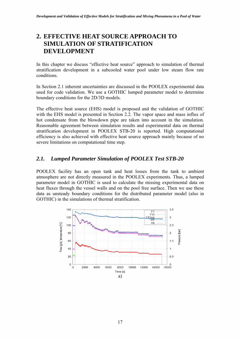
2.1. Lumped Parameter Simulation of POOLEX Test STB-20 POOLEX facility has an open tank and heat losses from the tank to ambient atmosphere are not directly measured in the POOLEX experiments. Thus, a lumped parameter model in GOTHIC is used to calculate the missing experimental data on heat fluxes through the vessel walls and on the pool free surface. Then we use these data as unsteady boundary conditions for the distributed parameter model (also in GOTHIC) in the simulations of thermal stratification.
a)
17

KTH, NKS-POOL May, 2011
b)
c)
Figure 4: POOLEX STB-20 [9]: a) steam injection conditions, b) history of vertical temperature distribution in heating phase and in c) cooling phase
Conditions and main results of the POOLEX STB-20 test [9] are presented in (Figure 4). The total duration of the STB-20 experiment was approximately 52 hours. The initial pool water temperature was 30 °C. During the first four hours, the pool water was heated with steam flow. The initial steam mass flow rate of 55 g/s was slowly reduced to 25 g/s as the experiment progressed to make sure that steam condenses inside the blowdown pipe and that the steam-water interface remains close to the blowdown pipe outlet [9]. Steam blowdown was terminated when the water maximum temperature in the upper part of the pool was 67 °C. After the heating phase, the pool water was cooled down for the next 48 hours [9].
18

Development and Validation of Effective Models for Stratification and Mixing Phenomena in a Pool of Water
Lab
Blowdown pipe
Water Pool
Steam Source
Atmosphere
Lab
Blowdown pipe
Water Pool
Steam Source
Atmosphere
Conductors
Figure 5: GOTHIC lumped parameter input model
Figure 6: POOLEX tank geometry representation in GOTHIC model
The lumped parameter model developed for simulation of POOLEX experiment is shown in Figure 5. First, the steam source is represented by the flow boundary condition (marked 1F). The experimental data, i.e., steam temperature, pressure, and flow rate [9] is used as time dependent flow boundary condition for 1F. Next, the atmosphere is modeled by a pressure boundary condition (2P) with constant pressure (1 bar) and temperature (20°C). The blowdown pipe, water pool, and the lab, are represented by volumes 1, 2s, and 3, respectively. The heat transfer between the blowdown pipe and the vapor phase is simulated by thermal conductor 1 while the heat transfer between the blowdown pipe and the liquid phase is simulated by thermal conductor 2. Similarly, the heat transfer between the vessel walls and the lab atmosphere are represented by thermal conductors 3, 4 and 5. The vapor part of the vessel sidewall is represented by conductors 3 while the liquid part is represented by conductor 4. Lastly, the bottom wall of the vessel is represented by conductor 5. The heat transfer coefficients for all heat conductors are calculated by default GOTHIC
19
KTH, NKS-POOL May, 2011
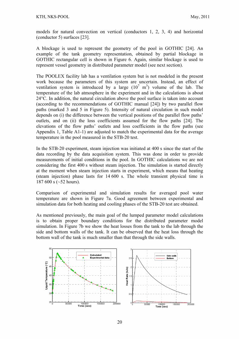
models for natural convection on vertical (conductors 1, 2, 3, 4) and horizontal (conductor 5) surfaces [23]. A blockage is used to represent the geometry of the pool in GOTHIC [24]. An example of the tank geometry representation, obtained by partial blockage in GOTHIC rectangular cell is shown in Figure 6. Again, similar blockage is used to represent vessel geometry in distributed parameter model (see next section). The POOLEX facility lab has a ventilation system but is not modeled in the present work because the parameters of this system are uncertain. Instead, an effect of ventilation system is introduced by a large (107 m3) volume of the lab. The temperature of the lab atmosphere in the experiment and in the calculations is about 24°C. In addition, the natural circulation above the pool surface is taken into account (according to the recommendations of GOTHIC manual [24]) by two parallel flow paths (marked 3 and 5 in Figure 5). Intensity of natural circulation in such model depends on (i) the difference between the vertical positions of the parallel flow paths’ outlets, and on (ii) the loss coefficients assumed for the flow paths [24]. The elevations of the flow paths’ outlets and loss coefficients in the flow paths (see Appendix 1, Table A1-1) are adjusted to match the experimental data for the average temperature in the pool measured in the STB-20 test. In the STB-20 experiment, steam injection was initiated at 400 s since the start of the data recording by the data acquisition system. This was done in order to provide measurements of initial conditions in the pool. In GOTHIC calculations we are not considering the first 400 s without steam injection. The simulation is started directly at the moment when steam injection starts in experiment, which means that heating (steam injection) phase lasts for 14 600 s. The whole transient physical time is 187 600 s (~52 hours). Comparison of experimental and simulation results for averaged pool water temperature are shown in Figure 7a. Good agreement between experimental and simulation data for both heating and cooling phases of the STB-20 test are obtained. As mentioned previously, the main goal of the lumped parameter model calculations is to obtain proper boundary conditions for the distributed parameter model simulation. In Figure 7b we show the heat losses from the tank to the lab through the side and bottom walls of the tank. It can be observed that the heat loss through the bottom wall of the tank is much smaller than that through the side walls.
20

Development and Validation of Effective Models for Stratification and Mixing Phenomena in a Pool of Water
a) b) Figure 7: Lumped parameter model results:
a) averaged water temperature in the tank; b) heat fluxes to the vessel walls The CPU time for calculation of STB-20 whole transient, including heating and cooling phases (187 600 s of physical time), with lumped parameter model is about 250 seconds on a PC Pentium IV with 2.8 GHz processor.
21

KTH, NKS-POOL May, 2011
2.2. Effective Heat Source Approach to Simulation of Stratification Development at Small Rate of Steam Injection
We consider two characteristic regimes of steam injection into a water pool (Figure 8). The first regime (Figure 8a) is characterized by a considerable amount of a non-condensed steam (or non-condensable gases) that flows out of the blowdown pipe. The second (Figure 8b) is normally a result of relatively small flow rate of pure steam when all steam is condensed inside the blowdown pipe and only a hot condensate with low momentum flows out of the pipe. In the first regime (Figure 8a) steam/gases flowing out of the pipe can create considerable momentum which may cause significant mixing and breakdown of stratification in the pool. This is addressed in detail in Chapter 3. In the second regime (Figure 8b) steam injection provides negligible source of momentum which does not induce significant mixing in the pool while it provides considerable heat source for development of thermal stratification in the pool. This regime is experimentally investigated in POOLEX test STB-20 [9] (Figure 4). Steam flow rate is controlled and the position of the water free surface is kept close to the outlet and inside the blowdown pipe [9]. As a result strong thermal stratification has developed during the heating phase of the experiment [9] (Figure 4).
a) large flow rate of steam b) small flow rate of steam
Figure 8: Two regimes of steam injection into a subcooled water pool.
As it is shown in the previous section, modeling of direct steam injection with GOTHIC in this regime gives inadequate results, that is, mixing is predicted instead of stratification development.
22
Development and Validation of Effective Models for Stratification and Mixing Phenomena in a Pool of Water
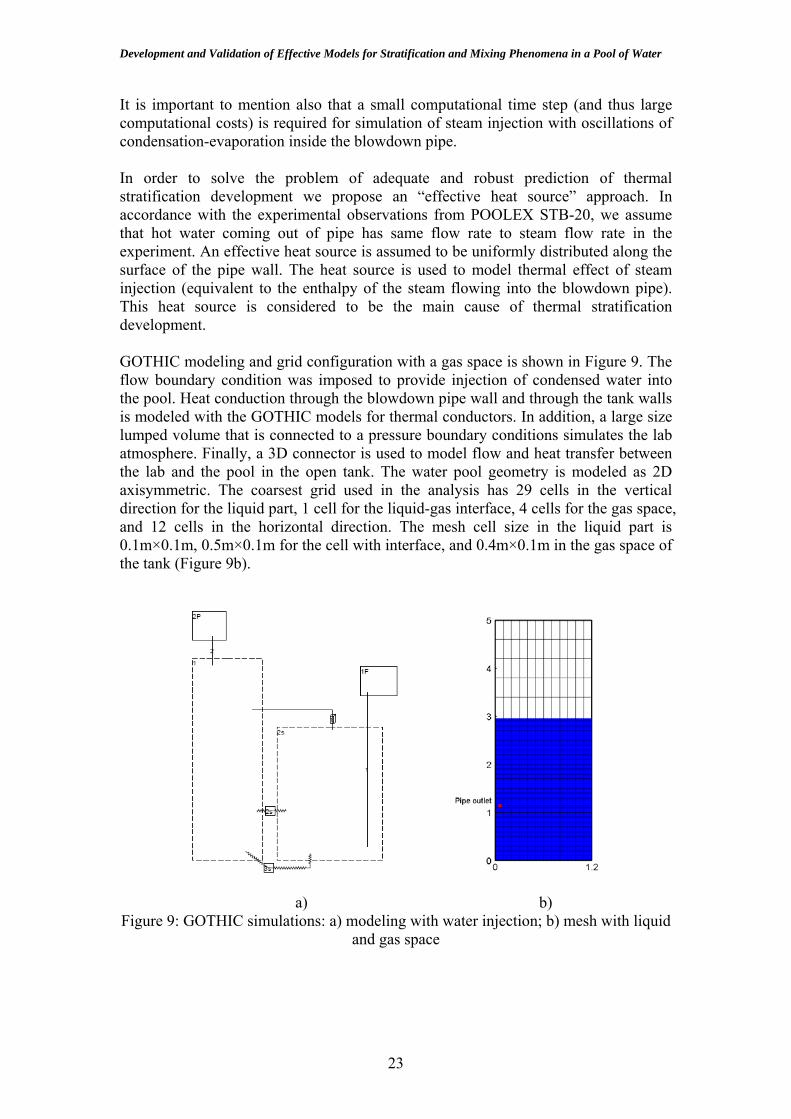
It is important to mention also that a small computational time step (and thus large computational costs) is required for simulation of steam injection with oscillations of condensation-evaporation inside the blowdown pipe. In order to solve the problem of adequate and robust prediction of thermal stratification development we propose an “effective heat source” approach. In accordance with the experimental observations from POOLEX STB-20, we assume that hot water coming out of pipe has same flow rate to steam flow rate in the experiment. An effective heat source is assumed to be uniformly distributed along the surface of the pipe wall. The heat source is used to model thermal effect of steam injection (equivalent to the enthalpy of the steam flowing into the blowdown pipe). This heat source is considered to be the main cause of thermal stratification development. GOTHIC modeling and grid configuration with a gas space is shown in Figure 9. The flow boundary condition was imposed to provide injection of condensed water into the pool. Heat conduction through the blowdown pipe wall and through the tank walls is modeled with the GOTHIC models for thermal conductors. In addition, a large size lumped volume that is connected to a pressure boundary conditions simulates the lab atmosphere. Finally, a 3D connector is used to model flow and heat transfer between the lab and the pool in the open tank. The water pool geometry is modeled as 2D axisymmetric. The coarsest grid used in the analysis has 29 cells in the vertical direction for the liquid part, 1 cell for the liquid-gas interface, 4 cells for the gas space, and 12 cells in the horizontal direction. The mesh cell size in the liquid part is 0.1m×0.1m, 0.5m×0.1m for the cell with interface, and 0.4m×0.1m in the gas space of the tank (Figure 9b).
a) b) Figure 9: GOTHIC simulations: a) modeling with water injection; b) mesh with liquid
and gas space
23

KTH, NKS-POOL May, 2011
Figure 10: Comparison of GOTHIC simulation and experimental data
Figure 10 shows the comparison of GOTHIC simulation to the experimental data. Temperature of the top layer during the first 4000 seconds is in good agreement with experimental data. However, after 4000 seconds the temperature levels in the part above the pipe outlet are under-predicted, while the temperature levels are over-predicted for the part below the pipe. This is attributed to the insufficient (12×30) grid resolution used in GOTHIC simulation.
24

Development and Validation of Effective Models for Stratification and Mixing Phenomena in a Pool of Water
25

KTH, NKS-POOL May, 2011
3. EFFECTIVE MOMENTUM APPROACH TO PREDICTION OF MIXING IN A POOL
The important parameter for operation of the pressure suppression pool is time scale for mixing of stratified layers. This time scale defines how fast condensation capacity of the pressure suppression pool can be restored. In this chapter we discuss “effective momentum source” approach to simulation of mixing of initially stratified water pool. Importance of both direction and magnitude of effective momentum for mixing patterns in the pool is identified. It is demonstrated that it is possible to predict time scales for mixing in different layers of the pool if direction and magnitude of effective momentum are properly selected.
3.1. Development and Implementation of Effective Momentum Approach in GOTHIC
In the present chapter we use the GOTHIC code for prediction of 2D mixing phenomena in a pool, and we use concept of effective momentum in order to take into account influence of gas injection into the pool. For validation of the simulation approach we use data on mixing of initially stratified pool in the POOLEX experiment STB-21 [9]. Figure 11 shows steam flow rate and temperature history measured in the test STB-21 of POOLEX experiment at different elevation in the pool. The experiment has five phases for different phenomenon. In phase A, mixing was observed before 1800 s (line 0 in Figure 11). At 1800 s of phase B, thermal stratification began to develop in the layer above the pipe outlet. In phase C at 3250 s (line 1 in Figure 11), the temperature of the layer below pipe was stabilized at a constant value. The second mixing phase caused by chugging started at about 4200 s (line 2 in Figure 11) in phase D when injected steam flow rate was rapidly increased. The complete mixing was obtained in phase E at about 4900 s (line 3 in Figure 11) when the topmost layer of the pool reached the same temperature as the other layers. This is the time that steam flow rate reaches 210 g/s. The mixing time scale is considered to be 700 s long, that is, from 4200 s to 4900 s.
A B C D E
1 2 3
000
1 2 3
0
1 2 3
0
1 2 31 2 3
0
A B C D E
a) b)
26

Development and Validation of Effective Models for Stratification and Mixing Phenomena in a Pool of Water
Figure 11: a) Injected steam flow rate; b) Temporal history of vertical temperature distribution in STB-21 [9] (Phase A: First mixing. Phase B: Onset of stratification.
Phase C: Stratification. Phase D: Onset of second mixing. Phase E: second well mixing.)
The calculation of effective momentum for the case of steam venting through a vertical tube into a subcooled water pool is still considered an unsolved problem. The direction of effective momentum due to steam injection can change rapidly from downward to upward. Large scale motion of steam-water surface and buoyancy effects in small bubbles may counteract. Depending on steam mass flow rate and pool subcooling the steam injection can be in different unsteady oscillatory regimes [45]. It is impossible at the moment to simulate directly such kind of oscillatory regimes in GOTHIC due to lack of appropriate models and closures. Also effect of small bubbles generation and collapse on effective momentum has to be investigated. In the present work we use parametric simulations study with GOTHIC code and comparison with POOLEX STB-21 experimental data to investigate: how magnitude and direction of effective momentum can affect time scale for the pool mixing.
Pressure boundary
Lab
Conductor
Pump
Water pool
Figure 12: GOTHIC code model used for simulations with effective momentum
simulated by pump Figure 12 depicts the open tank of the POOLEX facility and positions of thermocouples as well as the model used for GOTHIC simulation. The pool with both vapor and liquid space is modeled as distributed parameter volume 2s with 2D axisymmetric system. The lab (volume 1) is represented with lumped parameter model. The approach to modeling of mixing phenomenon is the same as in the modeling of STB-20 of POOLEX. That is, heat source is used instead of modeling of direct steam injection. Heat rate calculated in STB-20 is used in the modeling in order to develop thermal stratification in the pool. To provide effective momentum induced by the steam injection, four pumps (1P~4P) have been added on the flow path 2-5, which connects two adjacent computational cells close to the outlet of the blowdown pipe.
27

KTH, NKS-POOL May, 2011
3.2. Feasibility Study of Effective Momentum Approach in GOTHIC by Comparison with STB-21 Test Data from POOLEX
The second mixing phase of the stratified layers in the experiment is of special interest because it provides specific experimental data needed for code validation. From 3250 s, steam flow rate is small and all of the steam is condensed inside the pipe according to the experimental observations. In the EHS model, we assume that all latent heat of steam condensation is distributed uniformly along the pipe wall and transferred to the pool. From the experimental data it can be seen that at 3250 s the temperature at the bottom of the tank is about 34.5 ℃ and the temperature at the top is
about 40 ℃. These experimental values of the temperatures measured at different elevations are imposed as initial conditions in GOTHIC simulations. The heat rate through the pipe wall is calculated according to injected steam flow rate and enthalpy as shown in Figure 13.
Figure 13: Heat rate through the pipe wall in GOTHIC calculation
Figure 14 shows results of GOTHIC simulation for the first 950 s and comparison with experimental data from 3250 s to 4200 s of phase C. Since injected steam flow rate is low and induced momentum is not sufficient to break the stratified layers, the thermal stratification continues to develop during this period. Figure 14a) shows temperature history in the part below the pipe exit. It can be seen that the GOTHIC simulation can predict well the temperature in this part which is relatively flat close to the level of 35 ℃. Figure 14b) shows temperature change in the part above the pipe exit where stratification is formed at the beginning. The GOTHIC simulation still can predict temperature well for most of the horizontal layers. There is about 1 ℃ difference between the experimental and simulation data for the layer at T108. There are several possible reasons for the under-prediction of the temperature. One reason is that global circulation present in the experiment is ignored in the simulation and pool is assumed to be at zero velocity as initial conditions. In the experiment, the thermal stratification actually started from 1800 s and the global circulation flow has already formed at that time. This global circulation will affect both thermal stratification development and mixing process. In GOTHIC simulation, it is impossible to model
28

Development and Validation of Effective Models for Stratification and Mixing Phenomena in a Pool of Water
this kind of global circulation as initial conditions. This is also one reason to start the simulation from 3250 s, and not from 4200 s, which is the start of the mixing process. It is assumed that this global circulation can be formed after 950 s in the simulation.
C
C
a) b) Figure 14: Temperature distribution in GOTHIC calculation with grid of 48×114 and compare to data in experiment from 3250s to 4200s. a) Part below pipe; b) part above
pipe exit
Figure 15a) shows temperature changes in one of the GOTHIC simulations for phase D with downward direction of the pump. In comparison to the experimental data in Figure 15b), temperature change in the simulation has the same trend as in the experiment. The only difference is that mixing time for the top layer in the simulation is shorter than that observed in the experiment. In the previous work we found that it is possible in principle to reproduce correctly mixing time scale if appropriate momentum rate of the pump is defined.
D D
a) b) Figure 15: Mixing process a) in the GOTHIC simulation with downward pump of
0.0777 m3/s with 48×114; b) in experiment.
The temperature distribution and the streamline in the water part of the tank at about 1260 seconds in one case are shown in Figure 16. The pump volumetric flow rate in the simulation is 0.09 m3/s. It can be seen from temperature distribution that the complete mixing is not achieved yet by that time and the top layer still has high temperature. The streamline showed that two global circulations exist in the water
29

KTH, NKS-POOL May, 2011
tank. The counter-clockwise circulation at low part is caused by pump and it results in mixing. The clockwise circulation at the upper part is due to buoyancy plume which drives the thermal stratification development. Since the momentum imposed by pump is bigger than that driven by plume, the mixing is propagated from bottom to top.
Figure 16: Temperature distribution and streamline in the water part of tank at about
1260 seconds in the simulation with pump volumetric speed of 0.09 m3/s. To provide quantitative comparison between experimental and simulation data on the effective momentum source we introduce two time scales of mixing in the layers below and above the pipe outlet respectively. In the mixing time scales predicted by GOTHIC for upper and lower layers of the pool are presented as a function of the momentum rate provided by the pump. Experimentally observed in the STB-21 test (two horizontal lines) time scales are also shown in the figures for comparison. As can be seen in Figure 17, the mixing time scale increases exponentially if the pump momentum rate is smaller than some threshold value. If downward direction of the effective momentum is used then time scale for mixing of the bottom layers is smaller than that for the upper layers. Analysis of the results suggests that the best agreement with the experimental data for the mixing time scales can be achieved in case of the downward direction of effective momentum rate about 89.379 kg-m/s2 and with grid resolution of 48×114. In this case both time scales of mixing in the top and bottom layers can be reproduced in the GOTHIC simulation simultaneously. The density of water is 993.148 kg/m3, since the water through the pump is under pool temperature with 35 ℃ to 40 ℃.
30

Development and Validation of Effective Models for Stratification and Mixing Phenomena in a Pool of Water
0
500
1000
1500
2000
2500
3000
0 100 200 300 400
Cha
ract
eris
tic m
ixin
g tim
e sc
ale
(sec
)
Momentum rate (kg-m/s2)
2.74 m in STB-211.24 m in STB-212.74 m with EMS1.24 m with EMS
Figure 17: Momentum rate vs. mixing time scale. The momentum rate on the red line is about 89.379 kg-m/s2.
31
KTH, NKS-POOL May, 2011
3.3. Momentum estimation based on STB-21 Test Data from POOLEX
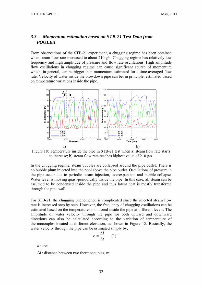
From observations of the STB-21 experiment, a chugging regime has been obtained when steam flow rate increased to about 210 g/s. Chugging regime has relatively low frequency and high amplitude of pressure and flow rate oscillations. High amplitude flow oscillations in chugging regime can cause significant source of momentum which, in general, can be bigger than momentum estimated for a time averaged flow rate. Velocity of water inside the blowdown pipe can be, in principle, estimated based on temperature variations inside the pipe.
∆t
a) b) Figure 18: Temperature inside the pipe in STB-21 test when a) steam flow rate starts
to increase; b) steam flow rate reaches highest value of 210 g/s.
In the chugging regime, steam bubbles are collapsed around the pipe outlet. There is no bubble plum injected into the pool above the pipe outlet. Oscillations of pressure in the pipe occur due to periodic steam injection, overexpansion and bubble collapse. Water level is moving quasi-periodically inside the pipe. In this case, all steam can be assumed to be condensed inside the pipe and thus latent heat is mostly transferred through the pipe wall.
For STB-21, the chugging phenomenon is complicated since the injected steam flow rate is increased step by step. However, the frequency of chugging oscillations can be estimated based on the temperatures monitored inside the pipe at different levels. The amplitude of water velocity through the pipe for both upward and downward directions can also be calculated according to the variation of temperature of thermocouples located at different elevation, as shown in Figure 18. Basically, the water velocity through the pipe can be estimated simply by,
tlvi Δ
Δ= (1)
where:
lΔ : distance between two thermocouples, m;
32

Development and Validation of Effective Models for Stratification and Mixing Phenomena in a Pool of Water
tΔ : time interval when thermocouples have same value for monitored temperature in one cycle, s.
Once the water velocity through the pipe is calculated, the momentum rate induced by the motion of water can be estimated by,
AvM ili2ρ= (2)
where:
lρ : water density, kg/m3.
iv : water velocity out of and into the pipe, i indicates downward/upward, m/s, and
A : flow area through by water, here we assume it is cross section area of pipe, m2.
a) b)
Figure 19: Calculated water velocity through the pipe in STB-21 test: a) steam flow rate increases from 60 g/s; b) steam flow rate reaches highest value of 210 g/s.
Figure 19 shows the water velocity calculated according to the temperatures measured in the middle and at the top of the pipe. Since there are only three thermocouples in the pipe with 900 mm distance each, experimental temperature measurements are not enough for accurate calculations of the water velocity. However, maximum water velocity in the upward and downward directions still can be estimated. Figure 19a) shows calculated velocity between 4540 s and 4600 s when injected steam flow rate is about 0.06 kg/s. Figure 19b) shows calculated velocity from 4860 s to 4900 s when injected steam flow rate is about 0.21 kg/s. We estimate that the averaged water velocity in water injection phase is about 1 m/s and cycle time period is about 4 s. The averaged water velocity in water suction phase is about 2.5 m/s and cycle time is about 2 s. The cross-section area of submerged pipe in POOLEX experiment is 0.036 m2. The water coming out from the pipe outlet is saturated condensate with a density of about 958.6 kg/m3. Therefore, the averaged downward momentum rate introduced by steam injection in chugging regime is about 34.51 kg-m/s2 and the averaged upward momentum rate is about 215.69 kg-m/s2.
33
KTH, NKS-POOL May, 2011
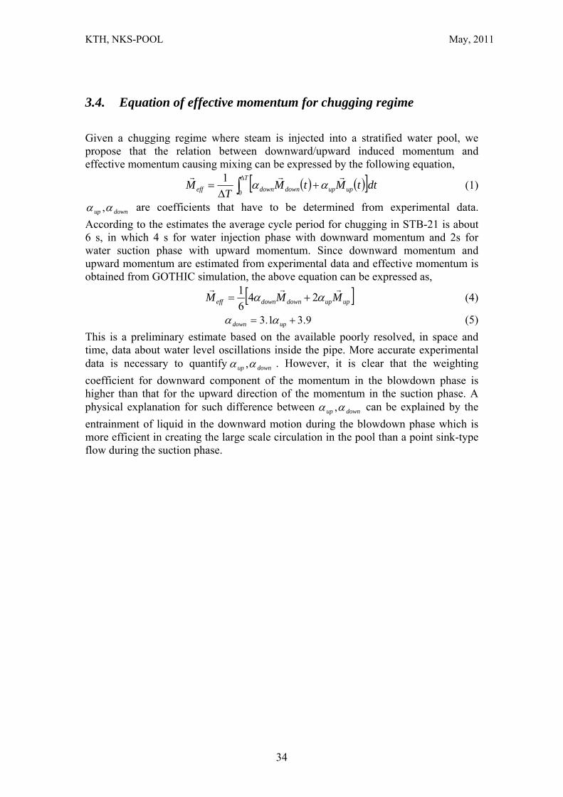
3.4. Equation of effective momentum for chugging regime
Given a chugging regime where steam is injected into a stratified water pool, we propose that the relation between downward/upward induced momentum and effective momentum causing mixing can be expressed by the following equation,
( ) ( )[ ]∫Δ
+Δ
=T
upupdowndowneff dttMtMT
M0
1 rrrαα (1)
downup αα , are coefficients that have to be determined from experimental data. According to the estimates the average cycle period for chugging in STB-21 is about 6 s, in which 4 s for water injection phase with downward momentum and 2s for water suction phase with upward momentum. Since downward momentum and upward momentum are estimated from experimental data and effective momentum is obtained from GOTHIC simulation, the above equation can be expressed as,
[ ]upupdowndowneff MMMrrr
αα 2461
+= (4)
9.31.3 += updown αα (5) This is a preliminary estimate based on the available poorly resolved, in space and time, data about water level oscillations inside the pipe. More accurate experimental data is necessary to quantify downup αα , . However, it is clear that the weighting coefficient for downward component of the momentum in the blowdown phase is higher than that for the upward direction of the momentum in the suction phase. A physical explanation for such difference between downup αα , can be explained by the entrainment of liquid in the downward motion during the blowdown phase which is more efficient in creating the large scale circulation in the pool than a point sink-type flow during the suction phase.
34

Development and Validation of Effective Models for Stratification and Mixing Phenomena in a Pool of Water
4. SIMULATION OF PPOOLEX TESTS WITH GOTHIC This chapter describes 2D distributed parameters simulations for PPOOLEX experiment performed as a part of analytical support to the experimental activity at LUT. Previous lumped parameter simulation shows reasonable agreement with experimental data on pressure and average liquid temperature both in drywell and wetwell. Uncertainty in the experimental data measurements has to be taken into account. Correction of input data (within the ranges of experimental measurement error) for the steam inlet pressure to be at saturation conditions can significantly improve qualitative agreement between experimental and simulation data. In the present chapter, 2D distributed parameter simulation against STR-01 and STR-04 of PPOOLEX will be discussed.
4.1. Simulations with 2D distributed Parameter Model The GOTHIC input for PPOOLEX experiment is shown in Figure 20. Drywell is represented by volume 1s. Volume 3 and volume 4 are representing blowdown pipe and the lab correspondingly. The large volume of 107m3 for lab is used. A blockage has also been used to model the real geometry of the drywell and wetwell (Figure 21 and Figure 22). The table in Appendix 2 includes all parameters used in PPOOLEX calculations. Six heat conductors are used in the input model of PPOOLEX. Conductors 1 and 2 are used for heat transfer from drywell to the lab through the ceiling and side wall, respectively. Conductor 3 simulates the heat transfer between the drywell and wetwell and Conductor 4 models the heat transfer from blowdown pipe to wetwell. Conductors 5 and 6 are used for heat transfer from wetwell to lab through the side wall and bottom, respectively.
Lab
Blowdownpipe
Wetwell
Drywell
Heat conductor
SourceAtmosphere
Lab
Blowdownpipe
Wetwell
Drywell
Heat conductor
SourceAtmosphere
Figure 20: Schematic of PPOOLEX input in GOTHIC
35

KTH, NKS-POOL May, 2011
Heat conductors
Drywell Top
Figure 21: Representation of PPOOLEX drywell geometry in lumped model of GOTHIC
(Detailed information for heat conductors is in Appendix 2)
Figure 22: Grid for wetwell of PPOOLEX
Two boundaries are used in the simulation for PPOOLEX experiment. Boundary 1 is connected to the drywell to supply the steam to inject into the drywell. Pressure boundary 2 is connected to the lab to keep the lab with atmospheric pressure. The results and initial conditions of the thermal stratification experiment with the PPOOLEX test facility has been presented in the NKS report [10]. Six experiments have been carried out and heat-up periods of several thousand seconds by steam injection into the drywell compartment and into the wetwell water pool are measured. Some tests have shown thermal stratification in the wetwell. In the present work, we
36

Development and Validation of Effective Models for Stratification and Mixing Phenomena in a Pool of Water
use experimental data from STR-01 and STR-04 tests to provide initial and boundary conditions. Flow boundary is used for modeling of steam supply.
4.2. 2D distributed parameter simulation for STR-01 STR-01 is a test with only cooling phase. There is no steam injection from inlet plenum in drywell of PPOOLEX facility. In this case, the steam mass flow rate of boundary is set to 0. Figure 23 compares calculated liquid temperature and measured liquid temperature. The simulation is terminated at about 75,000 s due to numerical disconvergence. A low temperature is observed in the experiment at the semi-spherical bottom of pool. This phenomenon is not predicted by GOTHIC, since in the 2D modeling, the bottom of tank is modeled by a flat blockage with 0.24 m in height. However, the result shows that the predicted temperature of the pool can match the experimental temperature. It implies that the heat loss from the tank to outside can be predicted by GOTHIC.
Figure 23: Comparison of calculated and measured liquid temperature in the wetwell
4.3. 2D distributed parameter simulation for STR-04 The steam flow rate in STR-04 is a function of time, and is shown in Figure 24. Figure 25 shows the predicted drywell pressure compared to measured drywell pressure in the experiment. After about 7000 seconds, the pressure in the simulation is under-predicted compared to the measured data, which is equal to the boundary pressure in the experiment. The liquid temperature distribution in the simulation is shown in Figure 26. The well mixing pool is obtained in the simulation and the thermal stratification observed in the experiment is not predicted in this case. It can explain why the pressure of drywell is under-predicted. The drywell pressure is relevant to pressure in gas space of the
37

KTH, NKS-POOL May, 2011
wetwell, in which non-condensable gas has accumulated. The gas temperature of wetwell controls the gas pressure. In the experiment, the gas space has high temperature due to the thermal stratification in the liquid part. Compared to the averaged liquid temperature of experiment, the pool temperature is overestimated in the simulation. It may be due to the condensation rate in the drywell and in the blowdown pipe which is smaller in the simulation and consequently more steam is injected into the pool. Figure 27 shows the steam flow rate between different parts. It can be seen that the steam mass flow rate out of the blowdown pipe has positive value in most of the transient, especially before 5000 seconds.
Figure 24: Steam flow rate supplied by flow boundary
Figure 25: Comparison of calculated pressure and measured pressure in the drywell
38

Development and Validation of Effective Models for Stratification and Mixing Phenomena in a Pool of Water
Figure 26: Calculated wetwell liquid temperature and averaged liquid temperature in the experiment
Figure 27: Vapor mass flow rate from boundary and through the blowdown pipe
39

KTH, NKS-POOL May, 2011
5. SUMMARY AND OUTLOOK The presented work contributes to the development of expertise at KTH in the field of containment thermal-hydraulics under the support of the NORTHNET Roadmap 3 (Containment Thermal Hydraulics). The use of data from POOLEX/PPOOLEX experiments at Lappeenranta University of Technology (LUT) is important element in development and validation of analytical methods in the present work. Main conclusions and results of the present work can be summarized as follows:
(i) Reliable and computationally affordable prediction of thermal stratification development and mixing time scales in case of steam injection into a large subcooled pool is a challenging problem for contemporary simulation methods. Major problems are due to long time of the plant transients, complex geometry, complex physics of mixed (forced/natural) turbulent convection at high Rayleigh numbers, and potential instabilities in direct contact condensation of steam in different flow regimes (Chapter 1).
(ii) The effective heat source (EHS) model and the effective momentum source (EMS) model are further developed in this work for prediction of thermal stratification and mixing dynamics in the pool. The models are used in the GOTHIC containment code for modeling of the effect of steam condensation phenomena on the large scale circulation in the pool. (Chapter 2).
(iii) A feasibility study has been performed with GOTHIC simulations to estimate the value of the effective momentum rate and direction in Chapter 3. The experimental data from the POOLEX STB-21 test are analyzed to estimate the velocity and period of free surface oscillations in the blowdown pipe in the chugging regime. The averaged momentum rate induced by water motion downward and upward is then estimated. An equation for the effective momentum is proposed and two coefficients for upward and downward momentum rates are introduced. Unfortunately, available experimental data is insufficient to uniquely determine these coefficients. Thus, the approach warrants additional data for validation and preferably with more temperature measurement points inside the blowdown pipe. In addition, the measurement frequency of 1 Hz also has to be increased for higher accuracy in the estimation of the water velocity. The abrupt increase and non-constant steam influx in the experiment caused significant variations in the amplitude and period of chugging oscillations which makes accurate estimations of the effective momentum difficult. Thus, an experiment with relatively constant steam flow rate is highly desirable for better estimation of the effective heat and momentum sources (Chapter 3).
(iv) 2D simulations of PPOOLEX experiment STR-01 and STR-04 have been performed as part of analytical support to the experimental activity at LUT (Chapter 4). Results have shown with 2D modeling the heat loss from experimental facility can be predicted by GOTHIC. The simulation with steam injection supplied by a flow boundary did not predict the thermal stratification. The reason is that steam is not completely condensed in the blowdown pipe (as in the experiments), which introduces a source of
40

Development and Validation of Effective Models for Stratification and Mixing Phenomena in a Pool of Water
momentum in the pool that causes mixing. The implementation of EHS/EMS for PPOOLEX tests is currently in progress.
41

KTH, NKS-POOL May, 2011
6. ACKNOWLEDGEMENT Financial support from the NORTHNET RM3 and Nordic Nuclear Safety Program (NKS) is greatly acknowledged.
42

Development and Validation of Effective Models for Stratification and Mixing Phenomena in a Pool of Water
7. REFERENCES 1. Varzaly, A.M., Grafton, W.A., Chang, H., Mitchell, M.K., “Mark III, 1977.
Confirmatory test program, 1: 3 scale condensation and stratification phenomena-test series 5807,” General Electric Report, NEDE-21596-P, March 1977.
2. Varzaly, A.M., Grafton, W.A., Seely, D.S., “Mark III, 1978. Confirmatory test program, full scale condensation and stratification phenomena-test series 5707,” General Electric Report, NEDE-21853-P, August 1978.
3. Varzaly, A.M., Yu, K.P., Kerinenen, J.A., “Mark III, 1980. Confirmatory test program, 1:9 area scale multicell condensation and stratification phenomena-test series 6003,” General Electric Report, NEDE-24720-P, January 1980.
4. Peterson, P.F., Rao, I.J., Schrock, V.E., “Transient thermal stratification in pools with shallow buoyant jets,” In: Hassan, Y.A., Hochreiter, L.E. (Eds.), Nuclear Reactor Thermal Hydraulics, HTD-Vol. 190. ASME, New York, pp. 55–62, 1991.
5. Kataoka, Y., Fukui, T., Hatamiya, S., “Experimental study on convection heat transfer along a vertical flat plate between different temperature pools,” ANS National Heat Transfer Conference, Minneapolis, 28-31 July, 1991.
6. Fox, R.J., “Temperature distribution in pools with shallow buoyant jets,” Fifth International Topical Meeting on Nuclear Reactor Thermal Hydraulics (NURETH-5), September 21-24, Salt Lake City, Utah. pp. 1227-1234, 1992.
7. Smith, B.L., Dury, T.V., Huggenberger, M., Nöthiger, N., “Analysis of single-phase mixing experiments in open pools,” In: Cheung, F.B., Peterson, P.F. (Eds.), Thermal Hydraulics of Advanced and Special Purpose Reactors, ASME HTD, vol. 209. ASME, New York, pp. 91-100, 1992.
8. Ling, C., Kyoung, S.W., Ishii, M., Lim, J., Han, J., “Suppression pool mixing and condensation tests in PUMA facility,” International Conference on Nuclear Engineering, ICONE, 2006.
9. Laine, J., Puustinen, M., “Thermal stratification experiments with the condensation pool test rig,” NKS-117, 2006.
10. Puustinen, M., Laine, J., Räsänen, A., “PPOOLEX experiments on thermal stratification and mixing”. Research report CONDEX 1/2008, NKS-198, 2009.
11. Norman, T.L., Park, H.S., Revankar, S.T., Ishii, M., Kelly, J.M., “Thermal stratification and mixing in an open water pool by submerged mixtures of steam and air,” ASME International Mechanical Engineering Congress and Exposition, IMECE2006 - Nuclear Engineering, 2006.
12. Peterson, P.F., “Scaling and analysis of mixing in large stratified volumes,” International Journal of Heat and Mass Transfer, 37, pp.97-106, 1994.
13. Peterson, P.F., Gamble, R., “Scaling for forced-convection augmentation of heat and mass transfer in large enclosures by injected jets,” Trans. Am. Nucl. Soc., 78, pp.265-266, 1998.
14. Gamble, R. E., Nguyen, T. T., Peterson, P. F., “Pressure suppression pool mixing in passive advanced BWR plants,” Nuclear Engineering and Design, 204, pp.321-336, 2000.
15. Kuhn, S.Z., Kang, H.K., Peterson, P.F., “Study of Mixing and Augmentation of Natural Convection Heat Transfer by a Forced Jet in a Large Enclosure,” Journal of Heat Transfer, Volume 124, Issue 4, pp. 660-666, 2002.
16. Zhao, H., “Computation of mixing in large stably stratified enclosures,” Ph.D. Dissertation. University of California, Berkeley, 2003.
43
KTH, NKS-POOL May, 2011
17. Niu, F., Zhao, H., Per F. Peterson, P.F., Joel Woodcock and Robert E. Henry, “Investigation of mixed convection in a large rectangular enclosure,” Nuclear Engineering and Design, Volume 237, Issue 10, May 2007, Pages 1025-1032.
18. Zhao, H., Peterson, P.F, “One-dimensional analysis of thermal stratification in AHTR and SFR coolant pools. Proceedings - 12th International Topical Meeting on Nuclear Reactor Thermal Hydraulics, NURETH-12, 2007.
19. Li, H., Kudinov, P., “An approach toward simulation and analysis of thermal stratification and mixing in a pressure suppression pool,” NUTHOS-7, Seoul, Korea, October 5-9, 2008, Paper 243.
20. Li, H. and Kudinov, P., “An Approach for Simulation of Mixing in a Stratified Pool with the GOTHIC code,” ANS Transactions, 2009.
21. Li, H. and Kudinov, P., “Effective Approaches to Simulation of Thermal Stratification and Mixing in a Pressure Suppression Pool,” CFD4NRS-3 Workshop, Bethesda, MD, USA, September 14-16, 2010.
22. Nourgaliev, R.R., Dinh, T.N., “The investigation of turbulence characteristics in an internally-heated unstably-stratified fluid layer,” Nuclear engineering and design, 178, pp.235-258, 1997.
23. “GOTHIC contaiment analysis package qualification report,” Version 7.2a (QA), EPRI, Palo Alto, CA, 2006.
24. “GOTHIC containment analysis package user manual,” Version 7.2a (QA), EPRI, Palo Alto, CA, 2006.
25. “GOTHIC containment analysis package technical manual,” Version 7.2a, EPRI, Palo Alto, CA, 2006.
26. “The Marviken Full Scale Containment Experiment, Second Series, Description of the Test Facility”, AB Atomenergi Sweden, MXB-101, March, 1977.
27. Andreani, M., “Pretest calculations of phase A of ISP-42 (PANDA) using the GOTHIC containment code and comparison with the experimental results,” Nuclear Technology, 148, pp.35-47, 2006.
28. Andreani, M., Putz, F., Dury, T.V., Gjerloev, C., Smith, B.L., “On the application of field codes to the analysis of gas mixing in large volumes: case studies using CFX and GOTHIC,” Annals of Nuclear Energy, Volume 30, Issue 6, April 2003, Pages 685-714.
29. Wiles, L.E., George, T.L., “Thermal-Hydraulic Analysis of the Nuclear Power Engineering Corporation Containment Experiments with GOTHIC,” Nuclear Technology, Volume 142, Number 1, April 2003, Pages 77-91.
30. Gavrilas, M., Todreas, N.E., Driscoll, M.J., “The design and evaluation of a passively cooled containment for a high-rating pressurized water reactor,” Nuclear Engineering and Design, Volume 200, Issues 1-2, August 2000, Pages 233-249.
31. Weimer, J.C., Faeth, G.M., Olson, D.R., “Penetration of vapor jets submerged in subcooled liquids,” American Institute of Chemical Engineering Journal 19 (3), 552-558, 1973.
32. Chun, M. H., Kim, Y. S., Park, J. W., “An investigation of direct condensation of steam jet in subcooled water,” International Communications in Heat and Mass Transfer, 23, pp.947-958, 1996.
33. Kim, Y. S., Park, J. W., Song, C. H., “Investigation of the steam-water direct contact condensation heat transfer coefficients using interfacial transport models,” International Communications in Heat and Mass Transfer, 31 n3, 397- 408, 2004.
34. Song, C. H., Cho, S., Kim, H. Y., Bae, Y. Y., Chung, M. K., “Characterization of direct contact condensation of steam jets discharge into a subcooled water,” IAEA TCM, PSI, Viligen, pp.1-12, 1998.
44

Development and Validation of Effective Models for Stratification and Mixing Phenomena in a Pool of Water
35. Kerney, P.J., Fathe, G.M., Olson, D.R., “Penetration characteristics of submerged jet,” American Institute of Chemical Engineering Journal 18 (3), 548-553, 1972.
36. Chun, M.H., Kim, Y.S., Park, J.W., “An investigation of direct condensation of steam jet in subcooled water,” International Communications in Heat and Mass Transfer 23, 947-958, 1996.
37. Kim, H.W., Bae, Y.Y., Song, C.H., Park, J.K., Choi, S.M., “Characterization of direct contact condensation of steam jets discharging into a subcooled water,” International Journal of Energy Research 25, 239-252, 2001.
38. Wu, X.Z., Yan, J.J., Shao, S.F., Cao, Y., Liu, J.P., “Experimental study on the condensation of supersonic steam jet submerged in quiescent subcooled water: steam plume shape and heat transfer,” International Journal of Multiphase Flow 33, 1296-1307, 2007.
39. Gebhart, B., Jaluria, Y., Mahajan, R.L., Sammakia, B., “Buoyancy Induced Flows and Transport.” Hemisphere, New York, 1988.
40. Kudo, A., Egusa, T., Toda, S., “Basic study on vapor suppression,” Proc. Fifth Int. Heat Transfer Conf. 3, pp.221-225, 1974.
41. Cumo, W., Farello, G.E., Ferrari, G., “Direct heat transfer in pressure–suppression systems,” Proc. Sixth Int. Heat Transfer Conf. 5, pp.101-106, 1978.
42. Simpson, M.E., Chan, C.K., “Hydrodynamics of a subsonic vapor jet in subcooled liquid,” J. Heat Transfer 104, 271-278, 1982.
43. Tin, G.D., Lavagno, E., Malandrone, M., “Pressure and temperature measurements in a vapour condensing jet,” Proc. Seventh Int. heat Transfer Conf. 6, 159-164, 1982.
44. Nariai, H., Aya, I., “Fluid and pressure oscillations occuring at direct contact condensation of steam flow with cold water,” Nucl. Eng. Des. 95, 35-45, 1986.
45. Lahey, R.T., Moody, F.J., “The Thermal Hydrualics of a Boiling Water Reactor, second ed.,” American Nuclear Society, Illinois, 582 p., 1993.
46. Fitzsimmons, G.W., Galyard, D.L, Nixon, R.B., Mann, M.J. and Yu, K.P., “Mark I Containment Program, Full Scale Test Program Final Report,” General Electric Report, NEDE-24539, August 1979.
47. Tanskanen V., Lakehal, D., Puustinen, M., “Validation of direct contact condensation CFD models against condensation pool experiment,” XCFD4NRS OECD Conf., Grenoble, Sep. 12-15, 2008.
48. Moon, Y.-T., Lee, H.-D., Park, G.-C., “CFD simulation of steam jet-induced thermal mixing in subcooled water pool,” Nuclear Engineering and Design, 239, pp.2849–2863, 2009.
49. Chan, C.K., Lee, C.K.B., “A regime map for direct contact condensation,” International Journal of Multiphase Flow, 8 (1), 11-20, 1982.
50. Liang, K.S., Griffith, P., “Experimental and analytical study of direct contact condensation of steam in water,” Nuclear Engineering and Design 147, 425-435, 1994.
51. Cho, S., Song, C.H., Park, C.K., Yang, S.K., Chung, M.K., “Experimental study on dynamic pressure pulse in direct contact condensation of steam Jets Discharging into Subcooled Water, NTHAS98, 291, 1997.
52. Youn, D.H., Ko, K.B., Lee, Y.Y., Kim, M.H., Bae, Y.Y., and Park, J.K., “The direct contact condensation of steam in a pool at low mass flux,” Journal of Nuclear Science and Technology, 40 (10), 881-885, 2003.
53. Petrovic-de With, A., Calay, R.K., and With, G., “Three dimensional regime map for direct contact condensation of steam injected into water,” International Journal of Heat and Mass Transfer, 50, 1762-1770, 2007.
45

KTH, NKS-POOL May, 2011
54. Song, C.H., Baek, W.P., Chung, M.K., and Park, J.K., “Multi-dimensional thermal-hydraulic phenomena in advanced nuclear reactor systems: current status and perspectives of the R&D program at KAERI,” Proceedings International Conference on Nuclear Reactor Thermal Hydraulics (NURETH-10), Seoul, Korea, October 5-9, Paper I00121, 2003.
55. Kang, H.S., Song, C.H., “CFD Analysis for Thermal Mixing in a Subcooled Water Tank under a High Steam Mass Flux Discharge Condition,” Nuclear Engineering and Design, 238 (3), 492-501, 2008.
56. Austin, S., and Baisley, D., “System 80+Summaryof Program to Evaluate DCRT Issues Related to the Safety Depressurization System and IRWST – Task 12,” ABB-CE Documentation, 1992.
57. Zurigat, Y.H., Ghajar, A.J., “Heat transfer and stratification in sensible heat storage systems,” In Thermal Energy Storage Systems and Applications. Eds. Dincer & Rosen. Wiley, New York. 2002.
46

Development and Validation of Effective Models for Stratification and Mixing Phenomena in a Pool of Water
Appendix 1
Table A1-1: Parameters for lumped parameter modeling of STB-20
INITIAL CONDITION Pool liquid and vapor temperature (ºC)
30
Pool pressure (kPa) 105.353 Liquid fraction in the pool 0.533 Pipe liquid and vapor temperature (ºC)
30
Pipe pressure (kPa) 101.353 Liquid fraction in the pipe 0.469 liquid and vapor temperature in lab (ºC)
24
Lab pressure (kPa) 101.353 Liquid fraction in lab 0 BOUNDARY 1 (Flow) Steam Source Pressure (kPa)
Time dependent experimental data [9]
Steam Flow (kg/s) Time dependent experimental data [9] Temperature (ºC) Time dependent experimental data [9] Steam Fraction 1 Elevation (m) 6.9 BOUNDARY 2 (Pressure) Pressure (kPa) 101.353 Temperature (ºC) 20 Air Fraction 1 Elevation (m) 9 VOLUME 1 (Blowdown pipe model) Volume (m3) 0.149 Hydraulics diameter (m) 0.2141 Bottom Elevation (m) 0.857 Height (m) 4.143 VOLUME 2s (Pool model) Volume (m3) 22.5 Hydraulic diameter (m) 2.4 Bottom Elevation (m) 0 Height (m) 5 VOLUME 3 (Lab model) Volume (m3) 107
Hydraulics diameter (m) 15 Bottom Elevation (m) -1
47
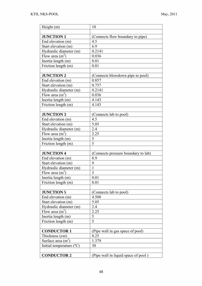
KTH, NKS-POOL May, 2011
Height (m) 10 JUNCTION 1 (Connects flow boundary to pipe) End elevation (m) 4.5 Start elevation (m) 6.9 Hydraulic diameter (m) 0.2141 Flow area (m2) 0.036 Inertia length (m) 0.01 Friction length (m) 0.01 JUNCTION 2 (Connects blowdown pipe to pool) End elevation (m) 0.857 Start elevation (m) 0.757 Hydraulic diameter (m) 0.2141 Flow area (m2) 0.036 Inertia length (m) 4.143 Friction length (m) 4.143 JUNCTION 3 (Connects lab to pool) End elevation (m) 4.5 Start elevation (m) 5.05 Hydraulic diameter (m) 2.4 Flow area (m2) 2.25 Inertia length (m) 5 Friction length (m) 5 JUNCTION 4 (Connects pressure boundary to lab) End elevation (m) 8.9 Start elevation (m) 9 Hydraulic diameter (m) 1 Flow area (m2) 3 Inertia length (m) 0.01 Friction length (m) 0.01 JUNCTION 5 (Connects lab to pool) End elevation (m) 4.508 Start elevation (m) 5.05 Hydraulic diameter (m) 2.4 Flow area (m2) 2.25 Inertia length (m) 5 Friction length (m) 5 CONDUCTOR 1 (Pipe wall in gas space of pool) Thickness (cm) 0.25 Surface area (m2) 1.379 Initial temperature (ºC) 30 CONDUCTOR 2 (Pipe wall in liquid space of pool )
48
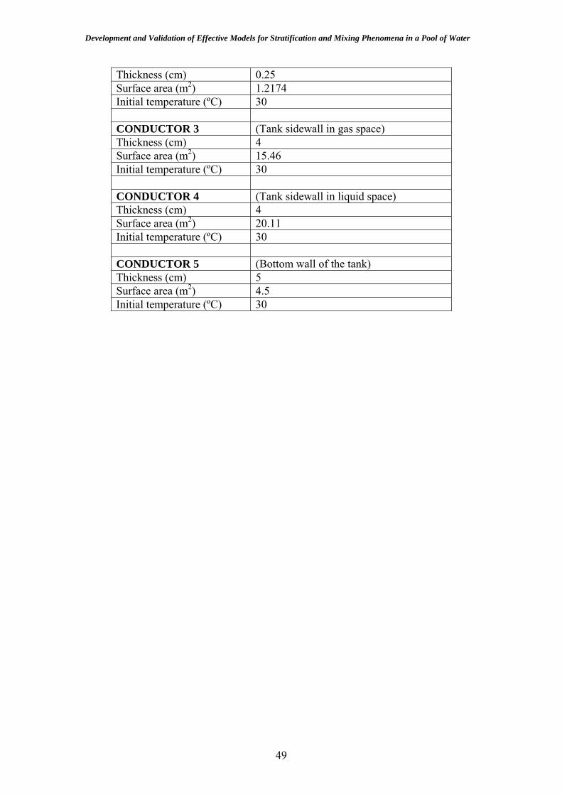
Development and Validation of Effective Models for Stratification and Mixing Phenomena in a Pool of Water
Thickness (cm) 0.25 Surface area (m2) 1.2174 Initial temperature (ºC) 30 CONDUCTOR 3 (Tank sidewall in gas space) Thickness (cm) 4 Surface area (m2) 15.46 Initial temperature (ºC) 30 CONDUCTOR 4 (Tank sidewall in liquid space) Thickness (cm) 4 Surface area (m2) 20.11 Initial temperature (ºC) 30 CONDUCTOR 5 (Bottom wall of the tank) Thickness (cm) 5 Surface area (m2) 4.5 Initial temperature (ºC) 30
49

KTH, NKS-POOL May, 2011
Table A1-2: Parameters for 2D modeling of STB-20 In 2D modeling of pool without gas space INITIAL CONDITION Pool liquid and vapor temperature (ºC)
30
Pool pressure (kPa) 105.353 liquid and vapor temperature in lab (ºC)
24
Lab pressure (kPa) 101.353 Liquid fraction in lab 0 VOLUME 1s (Liquid part of the pool) Volume (m3) 12 Hydraulic diameter (m) 2.4 Bottom Elevation (m) 1 Height (m) 2.95 VOLUME 2 (Lab model) Volume (m3) 107
Hydraulics diameter (m) 15 Bottom Elevation (m) -1 Height (m) 10 CONDUCTOR 1s (Pipe wall in liquid space of pool ) Thickness (cm) 0.25 Surface area (m2) 1.2174 Initial temperature (ºC) 30 CONDUCTOR 2s (Virtual wall of free surface in the pool ) Thickness (cm) 0.01 Surface area (m2) 4.5 Initial temperature (ºC) 30 CONDUCTOR 3s (Tank sidewall in liquid space) Thickness (cm) 4 Surface area (m2) 20.11 Initial temperature (ºC) 30 CONDUCTOR 4s (Bottom wall of the tank) Thickness (cm) 5 Surface area (m2) 4.5 Initial temperature (ºC) 30
In 2D modeling of pool without gas space INITIAL CONDITION Pool liquid and vapor temperature (ºC)
30
Pool pressure (kPa) 105.353
50
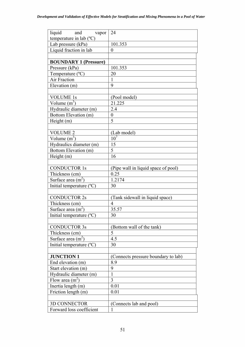
Development and Validation of Effective Models for Stratification and Mixing Phenomena in a Pool of Water
liquid and vapor temperature in lab (ºC)
24
Lab pressure (kPa) 101.353 Liquid fraction in lab 0 BOUNDARY 1 (Pressure) Pressure (kPa) 101.353 Temperature (ºC) 20 Air Fraction 1 Elevation (m) 9 VOLUME 1s (Pool model) Volume (m3) 21.225 Hydraulic diameter (m) 2.4 Bottom Elevation (m) 0 Height (m) 5 VOLUME 2 (Lab model) Volume (m3) 107
Hydraulics diameter (m) 15 Bottom Elevation (m) 5 Height (m) 16 CONDUCTOR 1s (Pipe wall in liquid space of pool) Thickness (cm) 0.25 Surface area (m2) 1.2174 Initial temperature (ºC) 30 CONDUCTOR 2s (Tank sidewall in liquid space) Thickness (cm) 4 Surface area (m2) 35.57 Initial temperature (ºC) 30 CONDUCTOR 3s (Bottom wall of the tank) Thickness (cm) 5 Surface area (m2) 4.5 Initial temperature (ºC) 30 JUNCTION 1 (Connects pressure boundary to lab) End elevation (m) 8.9 Start elevation (m) 9 Hydraulic diameter (m) 1 Flow area (m2) 3 Inertia length (m) 0.01 Friction length (m) 0.01 3D CONNECTOR (Connects lab and pool) Forward loss coefficient 1
51

KTH, NKS-POOL May, 2011
Reverse loss coefficient 1 Lumped volume momentum Conserve
52

Development and Validation of Effective Models for Stratification and Mixing Phenomena in a Pool of Water
Appendix 2 The following table includes parameters used in PPOOLEX 2D simulation with GOTHIC. The initial conditions and boundary conditions are from experimental data and different for STR-01 and STR-04.
BOUNDARY 1 (Flow) Elevation (m) 6.342 BOUNDARY 2 (Pressure) Pressure (kPa) 101.1 Temperature (ºC) 20 Air Fraction 1 Elevation (m) 9 VOLUME 1s (Dry well model) Volume (m3) 13.3 Hydraulics diameter (m) 2.4 Bottom Elevation (m) 4.27 Height (m) 3.18 VOLUME 2s (Wetwell model) Volume (m3) 17.8 Hydraulic diameter (m) 2.4 Bottom Elevation (m) 0 Height (m) 4.27 VOLUME 3 (Blowdown pipe model) Volume (m3) 0.1 Hydraulics diameter (m) 0.2 Bottom Elevation (m) 1.087 Height (m) 3.183 VOLUME 4 (Lab model) Volume (m3) 107
Hydraulics diameter (m) 15 Bottom Elevation (m) -1 Height (m) 10 JUNCTION 1 (Connects flow boundary to drywell) End elevation (m) 6.342 Start elevation (m) 6.342 Hydraulic diameter (m) 0.2141 Flow area (m2) 0.036 Inertia length (m) 0.01 Friction length (m) 0.01
53

KTH, NKS-POOL May, 2011
JUNCTION 2 (Connects drywell to blowdown pipe) End elevation (m) 4.27 Start elevation (m) 4.255 Hydraulic diameter (m) 0.2 Flow area (m2) 0.0314 Inertia length (m) 1.59 Friction length (m) 1.59 JUNCTION 3 (Connects blowdown pipe to wetwell) End elevation (m) 1.087 Start elevation (m) 1.067 Hydraulic diameter (m) 0.2 Flow area (m2) 0.0314 Inertia length (m) 1.59 Friction length (m) 1.59 CONDUCTOR 1 (Ceiling in the drywell) Thickness (cm) 1 Surface area (m2) 4.5 CONDUCTOR 2 (Side wall of drywell ) Thickness (cm) 1 Surface area (m2) 23.98 CONDUCTOR 3 (Floor between the drywell and wetwell) Thickness (cm) 1 Surface area (m2) 4.5 CONDUCTOR 4 (Blowdown tube model) Thickness (cm) 0.25 Surface area (m2) 2.0 CONDUCTOR 5 (Wetwell side wall) Thickness (cm) 1 Surface area (m2) 32.2 CONDUCTOR 6 (Bottom of the wetwell) Thickness (cm) 1 Surface area (m2) 4.5
54

Bibliographic Data Sheet NKS-248 Title Development and Validation of Effective Models for Simulation of Stratification
and Mixing Phenomena in a Pool of Water
Author(s) H. Li, P. Kudinov, W. Villanueva
Affiliation(s) Division of Nuclear Power Safety, Royal Institute of Technology, KTH, Sweden
ISBN 978-87-7893-320-1
Date June 2011
Project NKS-R / POOL
No. of pages 53 No. of tables 3 No. of illustrations 27 No. of references 57
Abstract This work pertains to the research program on Containment Thermal-Hydraulics at
KTH. The objective is to evaluate and improve performance of methods, which are used to analyze thermal-hydraulics of steam suppression pools in a BWR plant under different abnormal transient and accident conditions. The pressure suppression pool was designed to have the capability as a heat sink to cool and condense steam released from the core vessel and/or main steam line during loss of coolant accident (LOCA) or opening of safety relief valve in normal operation of BWRs. For the case of small flow rates of steam influx, thermal stratification could develop on the part above the blowdown pipe exit and significantly impede the pool’s pressure suppression capacity. Once steam flow rate increases significantly, momentum introduced by the steam injection and/or periodic expansion and collapse of large steam bubbles due to direct contact condensation can destroy stratified layers and lead to mixing of the pool water. We use CFD-like model of the general purpose thermal-hydraulic code GOTHIC for addressing the issues of stratification and mixing in the pool. In the previous works we have demonstrated that accurate and computationally efficient prediction of the pool thermal-hydraulics in the scenarios with transition between thermal stratification and mixing, presents a computational challenge. The reason is that direct contact condensation phenomena, which drive oscillatory motion of the water in the blowdown pipes, are difficult to simulate with original GOTHIC models because of appearance of artificial oscillations due to numerical disturbances. To resolve this problem we propose to model the effect of steam injection on the mixing and stratification with the Effective Heat Source (EHS) model and the Effective Momentum Source (EMS) model. We use POOLEX/PPOOLEX experiment (Lappeenranta University of Technology in Finland), in order to (a) quantify errors due to GOTHIC’s physical models and numerical schemes, (b) propose necessary improvements in GOTHIC sub-grid scale modeling, and (c) to validate proposed models. Results obtained with the EHS model shows that GOTHIC can predict development of thermal stratification in the pool if adequate grid resolution is provided. An equation for the effective momentum is proposed based on feasibility studies of the EMS model and analysis of the measured data in the test with chugging regime of steam injection. An experiment with higher resolution in space and time of oscillatory flow inside the blowdown pipe is highly desirable to uniquely determine model coefficients. Implementation of EHS/EMS model in GOTHIC and their validation against new PPOOLEX experiment is underway.
Key words BWR pressure suppression pool, thermal stratification, mixing, effective models, GOTHIC
Available on request from the NKS Secretariat, P.O.Box 49, DK-4000 Roskilde, Denmark. Phone (+45) 4677 4045, fax (+45) 4677 4046, e-mail [email protected], www.nks.org