nissan armada/titan w/ factory nav 2004-2007 table of … de luces de emergencia. 6. retire (2)...
TRANSCRIPT
METRA. The World’s best kits.™ metraonline.com © COPYRIGHT 2004-2015 METRA ELECTRONICS CORPORATION
REV.
11/
5/20
15
INST
99-7
629S
Installation instructions for part 99-7629S
CAUTION! Metra recommends disconnecting the negative bat-tery terminal before beginning any installation, unless the vehicle manufacturer recommends against so. Please check with your local Dealership for more information. All accessories, switches, climate controls panels, and especially air bag indicator lights must be con-nected before reconnecting the battery or cycling the ignition. Also, do not remove the factory radio with the key in the on position, or the vehicle running. It would be best to remove the key from the ignition and then wait a few seconds before removing the factory radio.
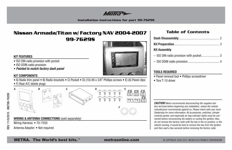
• ISO DIN radio provision with pocket• ISO DDIN radio provision• Painted to match factory dash panel
• A) Radio trim panel • B) Radio brackets • C) Pocket • D) (10) #8 x 3/8” Phillips screws • E) (6) Panel clips • F) Rear A/C delete plugs
KIT FEATURES
KIT COMPONENTS
WIRING & ANTENNA CONNECTIONS (sold separately)Wiring Harness: • 70-7550
Antenna Adapter: • Not required
• Panel removal tool • Phillips screwdriver • Torx T-10 driver
TOOLS REQUIRED
Nissan Armada/Titan w/ Factory NAV 2004-200799-7629S
A B C D E
F
Dash Disassembly ................................................. 2
Kit Preparation ....................................................... 3
Kit Assembly
– ISO DIN radio provision with pocket ...................... 3
– ISO DDIN radio provision ...................................... 4
Table of Contents
99-7629S
2
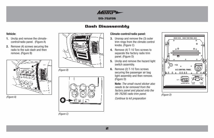
Vehicle:1. Unclip and remove the climate-
control/radio panel. (Figure A)
2. Remove (4) screws securing the radio to the sub-dash and then remove. (Figure B)
Climate-control/radio panel:3. Unsnap and remove the (3) outer
trim rings from the climate control knobs. (Figure C)
4. Remove (4) T-10 Torx screws to separate the factory radio trim panel. (Figure D)
5. Unclip and remove the hazard light switch assembly.
6. Remove (2) T-10 Torx screws securing the passenger air bag light assembly and then remove. (Figure D)
Note: The small round sticker also needs to be removed from the factory panel and placed onto the 99-7629S radio trim panel.
Continue to kit preparation
Dash Disassembly
CLIP
HAZARD SWITCH
PASSENGER AIR BAG LIGHT
T-10 TORX SCREW
T-10 TORX SCREW
A/C CONTROL PANEL
INSIDE VIEW - RADIO TRIM PANEL BACK
1
2
3
4
T-10
TOR
X S
CREW
S T-10 TORX SCREWS
1 2
(Figure D)(Figure A)
(Figure B)
OFF
(Figure C)

99-7629S
Kit Preparation Kit Assembly
(Figure A)
(Figure B)
ISO DIN radio provision with pocket
1. Secure the radio brackets to the pocket using (4) #8 x 3/8” Phillips screws supplied. (Figure A)
2. Remove the metal DIN sleeve and trim ring from the aftermarket radio.
3. Slide the radio in the pocket/bracket assembly, and then secure to the assembly using the screws provided with the radio. (Figure B)
4. Locate the factory wiring harness and antenna connector in the dash, and complete all necessary connections to the radio. Metra recommends using the proper mating adapter from Metra and/or AXXESS. Re-connect the negative battery terminal and test the radio for proper operation.
5. Reassemble the dash in reverse order of disassembly, using the 99-7629S radio trim panel.
3
To the 99-7629S radio trim panel:
1. Attach the factory climate controls using (4) #8 X 3/8” Phillips screws supplied. (Figure A)
2. Snap the outer trim rings onto the climate control knobs. (Figure B)
3. Attach the passenger air bag light assembly using (2) #8 X 3/8” Phillips screws supplied. (Figure C)
Note: Apply the small round airbag sticker previously removed to the air bag button.
4. Snap in the hazard light switch. (Figure D)
5. Attach (6) panel clips using the factory radio panel as a reference for clip positioning.
6. For models without rear A/C, snap in the (2) rear A/C delete plugs.
Continued to kit assembly
A/C
12
34
0
12
34
0
MAX A/C
RR
R
(Figure B)
A/COFF
12
34
0
12
34
0
MAX A/C
RR
R
(Figure D)
A/COFF
12
34
0
12
34
0
MAX A/C
RR
R
(Figure C)
A/C
12
34
0
12
34
0
MAX A/C
RR
R
(Figure A)
METRA. The World’s best kits.™ metraonline.com © COPYRIGHT 2004-2015 METRA ELECTRONICS CORPORATION
REV.
11/
5/20
15
INST
99-7
629S
KNOWLEDGE IS POWEREnhance your installation and fabrication skills by enrolling in the most recognized and respected mobile electronics school in our industry.Log onto www.installerinstitute.com or call 800-354-6782 for more information and take steps toward a better tomorrow.
Metra recommends MECP certified technicians
Installation instructions for part 99-7629S
IMPORTANTIf you are having difficulties with the installation of this product, please call our Tech Support line at 1-800-253-TECH. Before doing so, look over the instructions a second time, and make sure the installation was performed exactly as the instructions are stated. Please have the vehicle apart and ready to perform troubleshooting steps before calling.
Kit Assembly
(Figure A)
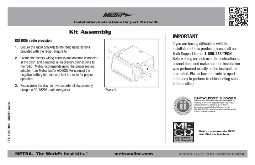
ISO DDIN radio provision
1. Secure the radio brackets to the radio using screws provided with the radio. (Figure A)
2. Locate the factory wiring harness and antenna connector in the dash, and complete all necessary connections to the radio. Metra recommends using the proper mating adapter from Metra and/or AXXESS. Re-connect the negative battery terminal and test the radio for proper operation.
3. Reassemble the dash in reverse order of disassembly, using the 99-7629S radio trim panel.
METRA. The World’s best kits.™ metraonline.com © COPYRIGHT 2004-2015 METRA ELECTRONICS CORPORATION
REV.
11/
5/20
15
INST
99-7
629S
Instrucciones de instalación para la pieza 99-7629S
¡PRECAUCIÓN! Meta recomienda desconectar la terminal negativa de la batería antes de iniciar cualquier instalación, a menos que el fabricante del vehículo recomiende lo contrario. Verifique con su concesionario local si existe más información. Todos los accesorios, interruptores, paneles de controles de clima y especialmente las lu-ces del indicador de las bolsas de aire deben estar conectados antes de reconectar la batería o ciclar la ignición. Además, no quite el radio de fábrica con la llave en la posición de encendido ni con el vehículo funcionando. Sería mejor retirar la llave de la ignición y esperar unos cuantos segundos antes de quitar el radio de fábrica.
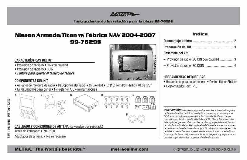
• Provisión de radio ISO DIN con cavidad• Provisión de radio ISO DDIN• Pintura para igualar el tablero de fábrica
• A) Panel de moldura de radio • B) Soportes del radio • C) Cavidad • D) (10) Tornillos Phillips #8 de 3/8” • E) (6) Ganchos para panel • F) Posterior A/C eliminar tapones
CARACTERÍSTICAS DEL KIT
COMPONENTES DEL KIT • Herramienta para quitar paneles • Destornillador Phillips • Destornillador Torx T-10
HERRAMIENTAS REQUERIDAS
Nissan Armada/Titan w/ Fábrica NAV 2004-200799-7629S Desmontaje tablero ............................................... 2
Preparación del kit ................................................ 3
Ensamble del kit
– Provisión de radio ISO DIN con cavidad ................ 3
– Provisión de radio ISO DDIN ................................. 4
Indice
A B C D E
F
CABLEADO Y CONEXIONES DE ANTENA (se venden por separado)Arnés de cableado: • 70-7550
Adaptador de antena: • No se requiere
99-7629S
2
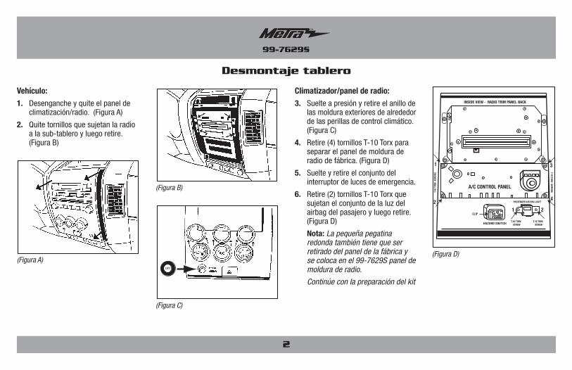
Vehículo:1. Desenganche y quite el panel de
climatización/radio. (Figura A)
2. Quite tornillos que sujetan la radio a la sub-tablero y luego retire. (Figura B)
Climatizador/panel de radio:3. Suelte a presión y retire el anillo de
las moldura exteriores de alrededor de las perillas de control climático. (Figura C)
4. Retire (4) tornillos T-10 Torx para separar el panel de moldura de radio de fábrica. (Figura D)
5. Suelte y retire el conjunto del interruptor de luces de emergencia.
6. Retire (2) tornillos T-10 Torx que sujetan el conjunto de la luz del airbag del pasajero y luego retire. (Figura D)
Nota: La pequeña pegatina redonda también tiene que ser retirado del panel de la fábrica y se coloca en el 99-7629S panel de moldura de radio.
Continúe con la preparación del kit
Desmontaje tablero
CLIP
HAZARD SWITCH
PASSENGER AIR BAG LIGHT
T-10 TORX SCREW
T-10 TORX SCREW
A/C CONTROL PANEL
INSIDE VIEW - RADIO TRIM PANEL BACK
1
2
3
4
T-10
TOR
X S
CREW
S T-10 TORX SCREWS
1 2
(Figura D)(Figura A)
(Figura B)
OFF
(Figura C)
99-7629S
Preparación del kit Ensamble del kit
(Figura A)
(Figura B)
Provisión de radio ISO DIN con cavidad
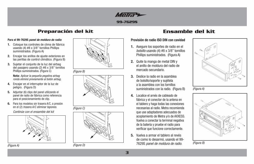
1. Asegure los soportes de radio en el bolsillo usando (4) #8 x 3/8” tornillos Phillips suministrados. (Figura A)
2. Quite la manga de metal DIN y el anillo de moldura del radio de mercado secundario.
3. Deslice la radio en la asamblea de bolsillo/soporte y sujétela a la asamblea con los tornillos suministrados con la radio. (Figura B)
4. Localice el arnés de cableado de fábrica y el conector de la antena en el tablero y haga todas las conexiones necesarias al radio. Metra recomienda que use adaptadores adecuados de acoplamiento de Metra y/o de AXXESS. Vuelva a conectar la terminal negativa de la batería y pruebe el radio para verificar que funcione correctamente.
5. Vuelva a armar el tablero al revés de como lo desarmó, usando el 99-7629S panel de moldura de radio.
3
Para el 99-7629S panel de moldura de radio:
1. Coloque los controles de clima de fábrica usando (4) #8 x 3/8” tornillos Phillips suministrados. (Figura A)
2. Encajar los anillos de ajuste exteriores en las perillas de control climático. (Figura B)
3. Sujetar el conjunto de la luz del airbag del pasajero usando (2) #8 x 3/8” tornillos Phillips suministrados. (Figura C)
Nota: Aplicar la pequeña pegatina airbag ronda eliminó previamente al botón airbag.
4. Encajar en el interruptor de la luz de peligro. (Figura D)
5. Adjuntar (6) clips del panel utilizando el panel de radio de fábrica como referencia para el posicionamiento de clip.
6. Para los modelos sin trasera A/C, a presión en el (2) trasera A/C eliminar tapones.
Continúe con el ensamble del kit
A/C
12
34
0
12
34
0
MAX A/C
RR
R
(Figure B)
A/COFF
12
34
0
12
34
0
MAX A/C
RR
R
(Figure D)
A/COFF
12
34
0
12
34
0
MAX A/C
RR
R
(Figure C)
A/C
12
34
0
12
34
0
MAX A/C
RR
R
(Figure A)
METRA. The World’s best kits.™ metraonline.com © COPYRIGHT 2004-2015 METRA ELECTRONICS CORPORATION
REV.
11/
5/20
15
INST
99-7
629S
KNOWLEDGE IS POWEREnhance your installation and fabrication skills by enrolling in the most recognized and respected mobile electronics school in our industry.Log onto www.installerinstitute.com or call 800-354-6782 for more information and take steps toward a better tomorrow.
Metra recomienda técnicos con certificación del Programa de Certificación en Electrónica Móvil (Mobile Electronics Certification Program, MECP).
EL CONOCIMIENTO ES PODERMejore sus habilidades de instalación y fabricación inscribiéndose en la escuela de dispositivos electrónicos móviles más reconocida y respetada de nuestra industria. Regístrese en www.installerinstitute.com o llame al 800-354-6782 para obtener más información y avance hacia un futuro mejor.
Instrucciones de instalación para la pieza 99-7629S
IMPORTANTESi tiene dificultades con la instalación de este producto, llame a nuestra línea de soporte técnico al 1-800-253-TECH. Antes de hacerlo, revise las instrucciones por segunda vez y asegúrese de que la instalación se haya realizado exactamente como se indica en las instrucciones. Por favor tenga el vehículo desarmado y listo para ejecutar los pasos de resolución de problemas antes de llamar.
Ensamble del kit
(Figura A)
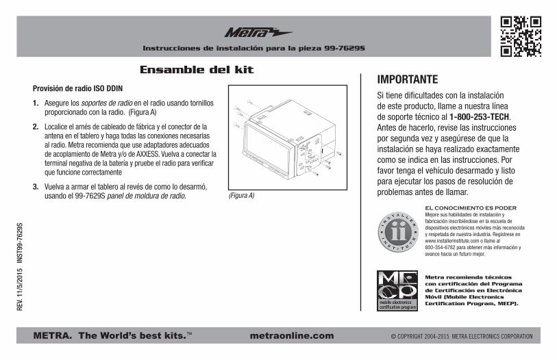
Provisión de radio ISO DDIN
1. Asegure los soportes de radio en el radio usando tornillos proporcionado con la radio. (Figura A)
2. Localice el arnés de cableado de fábrica y el conector de la antena en el tablero y haga todas las conexiones necesarias al radio. Metra recomienda que use adaptadores adecuados de acoplamiento de Metra y/o de AXXESS. Vuelva a conectar la terminal negativa de la batería y pruebe el radio para verificar que funcione correctamente
3. Vuelva a armar el tablero al revés de como lo desarmó, usando el 99-7629S panel de moldura de radio.