nissan armada (without nav) 2013-2015, armada 2008-2012
TRANSCRIPT
METRA - The World’s best kits ® metraonline.com
REV.
12/
8/20
16
INST
99-7
620B
Installation instructions for part 99-7620B
®
CAUTION! All accessories, switches, climate controls panels, and especially air bag indicator lights must be connected before cycling the ignition. Also, do not remove the factory radio with the key in the on position, or while the vehicle is running.
© COPYRIGHT 2016 METRA ELECTRONICS CORPORATION
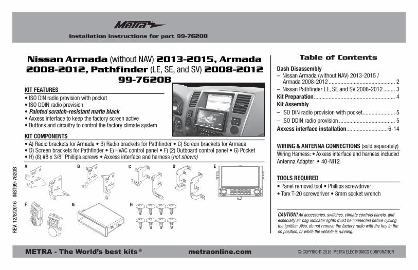
• ISO DIN radio provision with pocket• ISO DDIN radio provision• Painted scratch-resistant matte black• Axxess interface to keep the factory screen active• Buttons and circuitry to control the factory climate system
• A) Radio brackets for Armada • B) Radio brackets for Pathfinder • C) Screen brackets for Armada • D) Screen brackets for Pathfinder • E) HVAC control panel • F) (2) Outboard control panel • G) Pocket • H) (8) #8 x 3/8” Phillips screws • Axxess interface and harness (not shown)
KIT FEATURES
KIT COMPONENTS
WIRING & ANTENNA CONNECTIONS (sold separately)Wiring Harness: • Axxess interface and harness includedAntenna Adapter: • 40-NI12
• Panel removal tool • Phillips screwdriver • Torx T-20 screwdriver • 8mm socket wrench
TOOLS REQUIRED
Nissan Armada (without NAV) 2013-2015, Armada 2008-2012, Pathfinder (LE, SE, and SV) 2008-2012
99-7620B
A
F G H
C EB D
Dash Disassembly– Nissan Armada (without NAV) 2013-2015 / Armada 2008-2012 ............................................. 2– Nissan Pathfinder LE, SE and SV 2008-2012 ........ 3Kit Preparation ....................................................... 4Kit Assembly– ISO DIN radio provision with pocket ...................... 5– ISO DDIN radio provision ...................................... 5Axxess interface installation ............................6-14
Table of Contents
99-7620B
2
Dash Disassembly
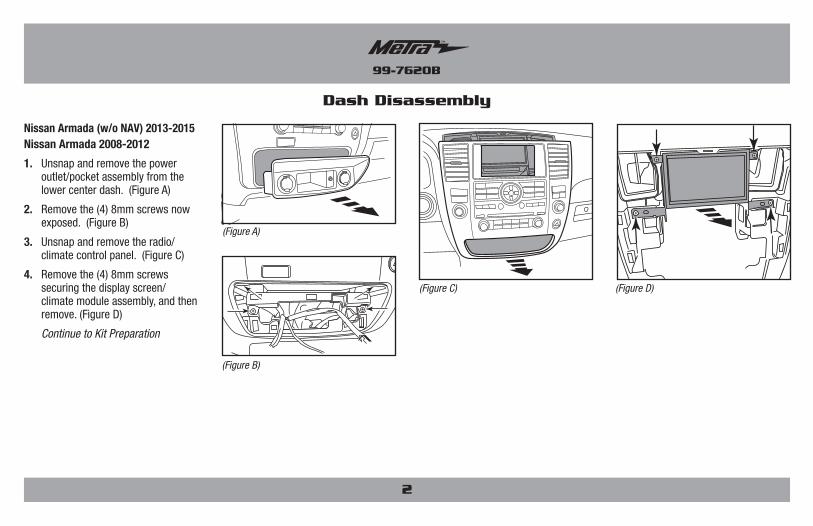
Nissan Armada (w/o NAV) 2013-2015 Nissan Armada 2008-2012
1. Unsnap and remove the power outlet/pocket assembly from the lower center dash. (Figure A)
2. Remove the (4) 8mm screws now exposed. (Figure B)
3. Unsnap and remove the radio/climate control panel. (Figure C)
4. Remove the (4) 8mm screws securing the display screen/climate module assembly, and then remove. (Figure D)
Continue to Kit Preparation
(Figure A)
(Figure B)
(Figure C) (Figure D)
99-7620B
3
Dash Disassembly
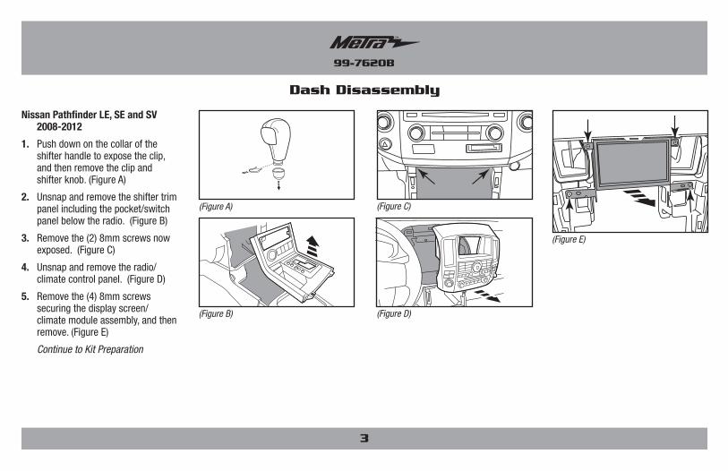
Nissan Pathfinder LE, SE and SV 2008-2012
1. Push down on the collar of the shifter handle to expose the clip, and then remove the clip and shifter knob. (Figure A)
2. Unsnap and remove the shifter trim panel including the pocket/switch panel below the radio. (Figure B)
3. Remove the (2) 8mm screws now exposed. (Figure C)
4. Unsnap and remove the radio/climate control panel. (Figure D)
5. Remove the (4) 8mm screws securing the display screen/climate module assembly, and then remove. (Figure E)
Continue to Kit Preparation
(Figure A)
(Figure D)(Figure B)
(Figure C)
(Figure E)
99-7620B
4
Kit Preparation
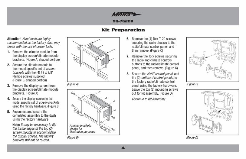
Attention! Hand tools are highly recommended as the factory dash may break with the use of power tools.
1. Remove the climate module from the display screen/climate module brackets. (Figure A, shaded portion)
2. Secure the climate module to the model specific set of screen brackets with the (4) #8 x 3/8” Phillips screws supplied. (Figure B, shaded portion)
3. Remove the display screen from the display screen/climate module brackets. (Figure A)
4. Secure the display screen to the model specific set of screen brackets using the factory hardware. (Figure B)
5. Reconnect and secure the completed assembly to the dash using the factory hardware.
Note: It may be necessary to file the inside edges of the top (2) screen mounts to accommodate the display screen. The factory brackets will not be reused.
6. Remove the (4) Torx T-20 screws securing the radio chassis to the radio/climate control panel, and then remove. (Figure C)
7. Remove the Torx screws securing the radio and climate controls buttons to the radio/climate control panel, and then remove. (Figure C)
8. Secure the HVAC control panel, and the (2) outboard control panels, to the factory radio/climate control panel using the factory hardware. Leave the top (2) mounting screws out for kit assembly. (Figure D)
Continue to Kit Assembly
(Figure C)
(Figure D)
(Figure A)
(Figure B)
Armada brackets shown for illustration purposes
99-7620B
Kit Assembly
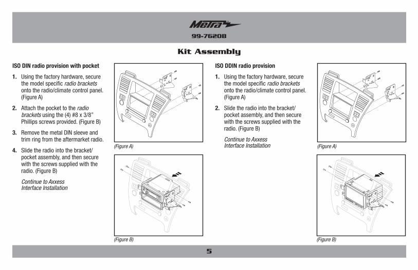
ISO DIN radio provision with pocket
1. Using the factory hardware, secure the model specific radio brackets onto the radio/climate control panel. (Figure A)
2. Attach the pocket to the radio brackets using the (4) #8 x 3/8” Phillips screws provided. (Figure B)
3. Remove the metal DIN sleeve and trim ring from the aftermarket radio.
4. Slide the radio into the bracket/pocket assembly, and then secure with the screws supplied with the radio. (Figure B)
Continue to Axxess Interface Installation
ISO DDIN radio provision
1. Using the factory hardware, secure the model specific radio brackets onto the radio/climate control panel. (Figure A)
2. Slide the radio into the bracket/pocket assembly, and then secure with the screws supplied with the radio. (Figure B)
Continue to Axxess Interface Installation
5
(Figure B) (Figure B)
(Figure A) (Figure A)
99-7620B
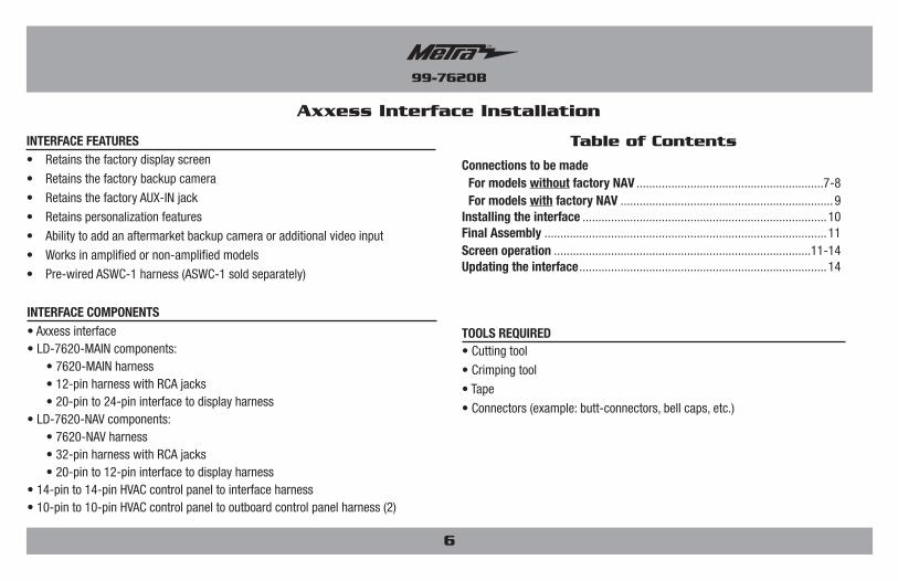
• Retains the factory display screen
• Retains the factory backup camera
• Retains the factory AUX-IN jack
• Retains personalization features
• Ability to add an aftermarket backup camera or additional video input
• Works in amplified or non-amplified models
• Pre-wired ASWC-1 harness (ASWC-1 sold separately)
INTERFACE FEATURES
• Cutting tool
• Crimping tool
• Tape
• Connectors (example: butt-connectors, bell caps, etc.)
TOOLS REQUIRED• Axxess interface• LD-7620-MAIN components: • 7620-MAIN harness • 12-pin harness with RCA jacks • 20-pin to 24-pin interface to display harness• LD-7620-NAV components: • 7620-NAV harness • 32-pin harness with RCA jacks • 20-pin to 12-pin interface to display harness• 14-pin to 14-pin HVAC control panel to interface harness• 10-pin to 10-pin HVAC control panel to outboard control panel harness (2)
INTERFACE COMPONENTS
Axxess Interface Installation
Connections to be made For models without factory NAV ...........................................................7-8 For models with factory NAV ...................................................................9Installing the interface .............................................................................10Final Assembly .........................................................................................11Screen operation .................................................................................11-14Updating the interface ..............................................................................14
Table of Contents
6
99-7620B
Connections to be made (for models without factory navigation)
7620-MAIN harness
For models without a BOSE amplifier: From the 20-pin harness to the aftermarket radio:
• Connect the Black wire with a ring terminal to chassis ground.
• Connect the Yellow wire to the battery wire.
• Connect the Red wire to the accessory wire.
• If the aftermarket radio has an illumination wire, connect the Orange wire to it.
• Connect the Gray wire to the right front positive speaker output.
• Connect the Gray/Black wire to the right front negative speaker output.
• Connect the White wire to the left front positive speaker output.
• Connect the White/Black wire to the left front negative speaker output.
• Connect the Green wire to the left rear positive speaker output.
• Connect the Green/Black wire to the left rear negative speaker output.
• Connect the Purple wire to the right rear positive speaker output.
• Connect the Purple/Black wire to the right rear negative speaker output.
• Disregard the 12-pin harness with RCA jacks, it will not be used in this application.
• Connect the Blue/Pink wire to the speed sense wire (if applicable).
• If retaining the factory AUX-IN jack, connect the Red and White RCA jacks labeled “AUX Input” to the AUX input.
• Disregard the Red and White RCA jacks labeled “From DVD”, they will not be used in this application.
• Disregard the Yellow RCA jack labeled “From DVD”, it will not be used in this application.
Note: This 16-pin harness must be connected for the factory backup camera to function. There are (2) 16-pin harnesses in the vehicle. Use the 16-pin harness that was connected into the factory radio chassis.
• If an aftermarket backup camera or external video source is desired to be displayed to the factory display screen, connect the Yellow RCA jack labeled “Backcam” to the desired source.
12-pin pre-wired ASWC-1 harness:
• This harness is to be used along with the optional ASWC-1 (not included) to retain steering wheel audio controls. If the ASWC-1 is not being used, disregard this harness. If it will be used, please refer to the ASWC-1 instructions for radio connections and programming.
Note: Disregard the harness that comes with the ASWC-1.
7
Continued on the next page
99-7620B
8
Connections to be made (for models without factory navigation) (Cont)
12-pin pre-wired ASWC-1 harness:
• This harness is to be used along with the optional ASWC-1 (not included) to retain steering wheel audio controls. If the ASWC-1 is not being used, disregard this harness. If it will be used, please refer to the ASWC-1 instructions for radio connections and programming.
Note: Disregard the harness that comes with the ASWC-1
From the 12-pin harness with RCA jacks to the aftermarket radio:
• Connect the Blue/White wire to the amp turn on wire. This wire must be connected to hear sound from the factory amplifier.
• Connect the White RCA to the left front RCA output.
• Connect the Gray RCA to the right front RCA output
• Connect the Green RCA to the left rear RCA output.
• Connect the Purple RCA to the right rear RCA output.
Continued to Installing the Interface
For models with a BOSE amplifier: From the 20-pin harness to the aftermarket radio:
• Connect the Black wire with a ring terminal to chassis ground.
• Connect the Yellow wire to the battery wire.
• Connect the Red wire to the accessory wire.
• If the aftermarket radio has an illumination wire, connect the Orange wire to it.
• Tape off and disregard the following (9) wires, they will not be used in this application: Gray, Gray/Black, Green, Green/Black, Purple, Purple/Black, White, White/Black, White/Blue.
• Connect the Blue/Pink wire to the speed sense wire (if applicable).
• If retaining the factory AUX-IN jack, connect the Red and White RCA jacks labeled “AUX Input” to the AUX input.
• Disregard the Red and White RCA jacks labeled “From DVD”, they will not be used in this application.
• Disregard the Yellow RCA jack labeled “From DVD”, it will not be used in this application.
Note: This 16-pin harness must be connected for the factory backup camera to function. There are (2) 16-pin harnesses in the vehicle. Use the 16-pin harness that was connected into the factory radio chassis.
• If an aftermarket backup camera or external video source is desired to be displayed to the factory display screen, connect the Yellow RCA jack labeled “Backcam” to the desired source.
99-7620B
9
Connections to be made (for models with factory navigation)
7620-MAIN harness From the 20-pin harness to the aftermarket radio:
• Connect the Black wire with a ring terminal to chassis ground.
• Connect the Yellow wire to the battery wire.
• Connect the Red wire to the accessory wire.
• If the aftermarket radio has an illumination wire, connect the Orange wire to it.
• Connect the White wire to the left front positive speaker output.
• Connect the White/Black wire to the left front negative speaker output.
• Connect the Gray wire to the right front positive speaker output.
• Connect the Gray/Black wire to the right front negative speaker output.
• Connect the Green wire to the left rear positive speaker output.
• Connect the Green/Black wire to the left rear negative speaker output.
• Connect the Purple wire to the right rear positive speaker output.
• Connect the Purple/Black wire to the right rear negative speaker output.
• Connect the Blue/Pink wire to the speed sense wire (if applicable).
12-pin pre-wired ASWC-1 harness:
• This harness is to be used along with the optional ASWC-1 (not included) to retain steering wheel audio controls. If the ASWC-1 is not being used, disregard this harness. If it will be used, please refer to the ASWC-1 instructions for radio connections and programming.
Note: Disregard the harness that comes with the ASWC-1.
From the 32-pin harness with RCA jacks to the aftermarket radio:
• If retaining the factory AUX-IN jack, connect the Red and White RCA jacks labeled “AUX Input” to the AUX input.
• Disregard the Red and White RCA jacks labeled “From DVD”, they will not be used in this application.
Continued to Installing the Interface
99-7620B
10
With the key in the off position:
For models without factory navigation:
1. Connect the 7620-MAIN harness into the interface, and then to the wiring harness in the vehicle.
2. Connect the 20-pin to 24-pin interface to display harness into the interface, and then to the 24-pin display harness in the vehicle.
3. Connect the 12-pin harness with RCA jacks to the wiring harness in the vehicle.
Attention! Extreme care must be taken when inserting the following harnesses. They can be forced in backwards and can permanently damage the kit if so.
4. Connect the 14-pin to 14-pin HVAC control panel to interface harness into the interface, and then to the HVAC control panel.
5. Connect the 10-pin to 10-pin HVAC control panel to outboard control panel harness into the HVAC control panel, and then to the outboard control panel. The right side connector on the HVAC control panel will go to the right side outboard control panel, and likewise for the left side.
For models with factory navigation:
1. Connect the 7620-NAV harness into the interface, and then to the wiring harness in the vehicle.
2. Connect the 20-pin to 12-pin interface to display harness into the interface, and then to the 12-pin display harness in the vehicle.
3. Connect the 32-pin harness with RCA jacks to the wiring harness in the vehicle.
Attention! Extreme care must be taken when inserting the following harnesses. They can be forced in backwards and can permanently damage the kit if so.
4. Connect the 14-pin to 14-pin HVAC control panel to interface harness into the interface, and then to the HVAC control panel.
5. Connect the 10-pin to 10-pin HVAC control panel to outboard control panel harness into the HVAC control panel, and then to the outboard control panel. The right side connector on the HVAC control panel will go to the right side outboard control panel, and likewise for the left side.
Installing the Interface
99-7620B
11
1. Locate the factory antenna connector in the dash and complete all necessary connections to the radio. Metra recommends using the proper mating adapter from Metra.
2. Before using the kit it must be initialized.
Attention! If the interface loses power for any reason, the following steps will need to be performed again. Also, if installing an ASWC-1 connect it after you initialize and test the interface/radio, with the key in the off position.
a. Turn the key (or push-to-start button) to the ignition position and wait until the factory display screen comes on. The screen should come on within 30 seconds.
Note: If the screen does not come on, turn the key to the off position, disconnect the interface, check all connections, reconnect the interface, and then try again. Ensure that the display harness is connected.
b. Start the vehicle and test all functions of the installation for proper operation, before reassembling the dash.
Note: The rear seat climate controls (if applicable) will no longer function with this kit.
3. Secure the completed assembly into the dash, and then reassemble the dash in reverse order of disassembly.
Final assembly
Continued on the next page
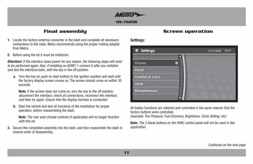
All button functions are retained and controlled in the same manner that the factory buttons were controlled. (example: Tire Pressure, Fuel Economy, Brightness, Clock Setting, etc).
Note: The 2 blank buttons on the HVAC control panel will not be used in this application.
Settings:
Screen operation
99-7620B
12
Screen operation (Cont)
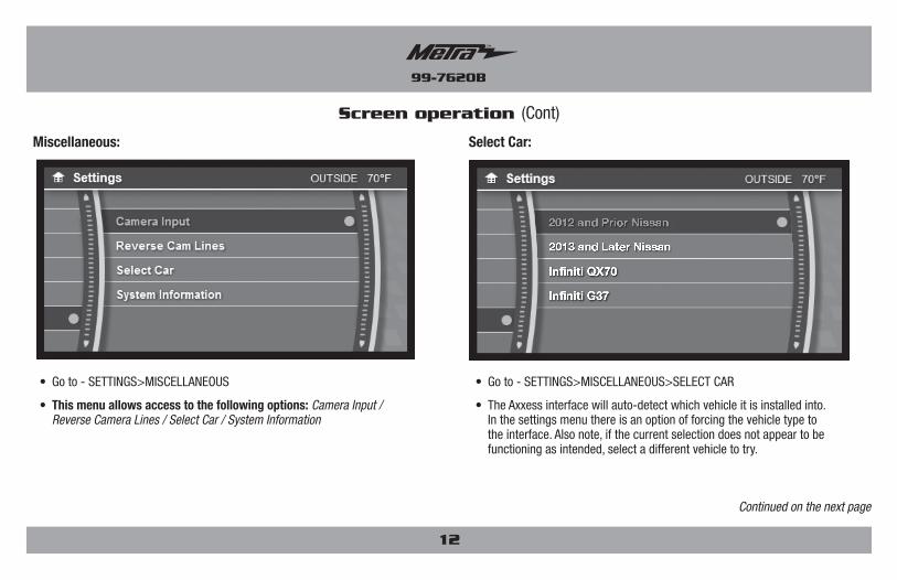
• Go to - SETTINGS>MISCELLANEOUS>SELECT CAR
• The Axxess interface will auto-detect which vehicle it is installed into. In the settings menu there is an option of forcing the vehicle type to the interface. Also note, if the current selection does not appear to be functioning as intended, select a different vehicle to try.
• Go to - SETTINGS>MISCELLANEOUS
• This menu allows access to the following options: Camera Input / Reverse Camera Lines / Select Car / System Information
Select Car:Miscellaneous:
Continued on the next page

99-7620B
13
Screen operation (Cont)
Reverse Cam Lines:
Continued on the next page
Camera input:
• Go to – SETTINGS> MISCELLANEOUS>CAMERA INPUT
• The factory back-up camera will continue to function by default. No extra steps are required.
• If an aftermarket backup camera is desired to be displayed onto the factory display screen, select “Aftermarket Backup Cam”.
• For non-nav models only: If an external video source (AUX-VIDEO) is desired to be displayed onto the factory display screen, select “Backup Cam Disabled”.
• To activate AUX-VIDEO, press the blank button on the right outboard controller. AUX-VIDEO will only function while the vehicle is in park.
• Go to – SETTINGS>MISCELLANEOUS> REVERSE CAM LINES
• The reverse camera lines are off by default.
• Turn on to activate the reverse camera lines; off to deactivate them.
99-7620B
14
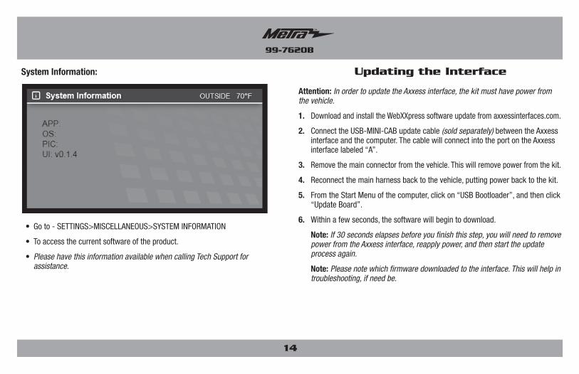
Attention: In order to update the Axxess interface, the kit must have power from the vehicle.
1. Download and install the WebXXpress software update from axxessinterfaces.com.
2. Connect the USB-MINI-CAB update cable (sold separately) between the Axxess interface and the computer. The cable will connect into the port on the Axxess interface labeled “A”.
3. Remove the main connector from the vehicle. This will remove power from the kit.
4. Reconnect the main harness back to the vehicle, putting power back to the kit.
5. From the Start Menu of the computer, click on “USB Bootloader”, and then click “Update Board”.
6. Within a few seconds, the software will begin to download.
Note: If 30 seconds elapses before you finish this step, you will need to remove power from the Axxess interface, reapply power, and then start the update process again.
Note: Please note which firmware downloaded to the interface. This will help in troubleshooting, if need be.
Updating the Interface
• Go to - SETTINGS>MISCELLANEOUS>SYSTEM INFORMATION
• To access the current software of the product.
• Please have this information available when calling Tech Support for assistance.
System Information:

99-7620B
15
Notes

METRA - The World’s best kits ® metraonline.com © COPYRIGHT 2016 METRA ELECTRONICS CORPORATION
REV.
12/
8/20
16
INST
99-7
620B
KNOWLEDGE IS POWEREnhance your installation and fabrication skills by enrolling in the most recognized and respected mobile electronics school in our industry.Log onto www.installerinstitute.com or call 800-354-6782 for more information and take steps toward a better tomorrow.
Metra recommends MECP certified technicians
Installation instructions for part 99-7620B
®
IMPORTANTIf you are having difficulties with the installation of this product, please call our Tech Support line at 1-800-253-TECH. Before doing so, look over the instructions a second time, and make sure the installation was performed exactly as the instructions are stated. Please have the vehicle apart and ready to perform troubleshooting steps before calling.
METRA - The World’s best kits ® metraonline.com
REV.
12/
8/20
16
INST
99-7
620B
Instrucciones de instalación para la pieza 99-7620B
®
¡PRECAUCIÓN! Todos los accesorios, interruptores, paneles de con-troles de clima y especialmente las luces del indicador de las bolsas de aire deben estar conectados antes ciclar la ignición. Además, no quite el radio de fábrica con la llave en la posición o de encendido ni con el vehículo funcionando.
© COPYRIGHT 2016 METRA ELECTRONICS CORPORATION
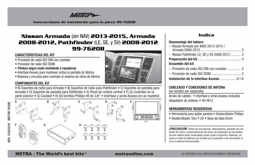
• Provisión de radio ISO DIN con cavidad• Provisión de radio ISO DDIN• Pintura negra mate resistente a rayaduras• Interfase Axxess para mantener activa la pantalla de fábrica• Botones y circuitos para controlar el sistema de clima de fábrica
• A) Soportes de radio para Armada • B) Soportes de radio para Pathfinder • C) Soportes de pantalla para Armada • D) Soportes de pantalla para Pathfinder • E) Panel de control central • F) (2) controles en la parte exterior • G) Cavidad • H) (8) tornillos Phillips #8 de 3/8” • Interfase y arnés Axxess (no se muestra)
CARACTERÍSTICAS DEL KIT
COMPONENTES DEL KITCABLEADO Y CONEXIONES DE ANTENA (se venden por separado)Arnés de cables: • Interfase y arnés Axxess incluidosAdaptador de antena: • 40-NI12
• Herramienta para quitar paneles • Destornillador Phillips • Destornillador Torx T-20 • llave de tubo 8mm
HERRAMIENTAS REQUERIDAS
Nissan Armada (sin NAV) 2013-2015, Armada 2008-2012, Pathfinder (LE, SE, y SV) 2008-2012
99-7620B
A
F G H
C EB D
Desmontaje del tablero– Nissan Armada (sin NAV) 2013-2015 / Armada 2008-2012 ............................................. 2– Nissan Pathfinder LE, SE y SV 2008-2012 ............ 3Preparación del kit ................................................ 4Ensamble del kit– Provisión de radio ISO DIN con cavidad ................ 5– Provisión de radio ISO DDIN ................................. 5Instalación de la interfase Axxess ...................6-14
Indice
99-7620B
2
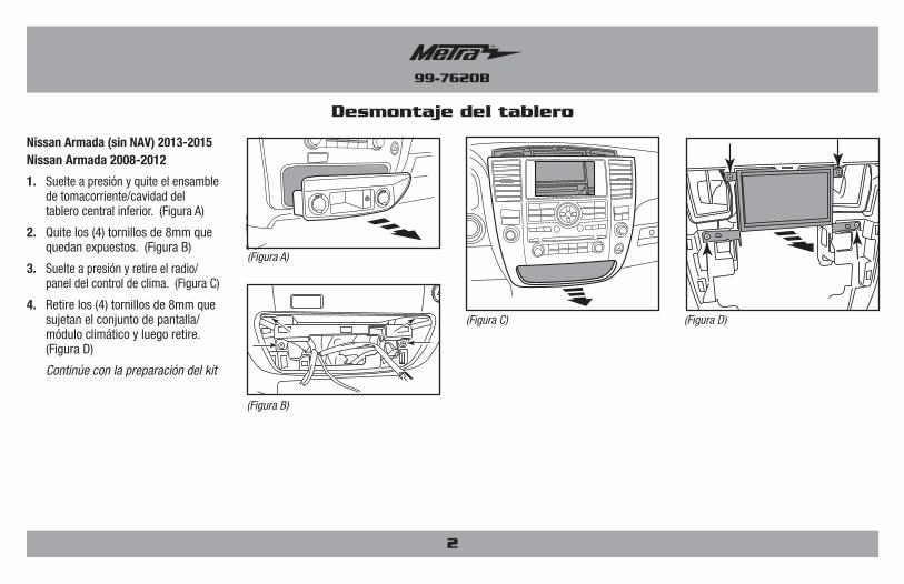
Desmontaje del tablero
Nissan Armada (sin NAV) 2013-2015 Nissan Armada 2008-2012
1. Suelte a presión y quite el ensamble de tomacorriente/cavidad del tablero central inferior. (Figura A)
2. Quite los (4) tornillos de 8mm que quedan expuestos. (Figura B)
3. Suelte a presión y retire el radio/panel del control de clima. (Figura C)
4. Retire los (4) tornillos de 8mm que sujetan el conjunto de pantalla/módulo climático y luego retire. (Figura D)
Continúe con la preparación del kit
(Figura A)
(Figura B)
(Figura C) (Figura D)
99-7620B
3
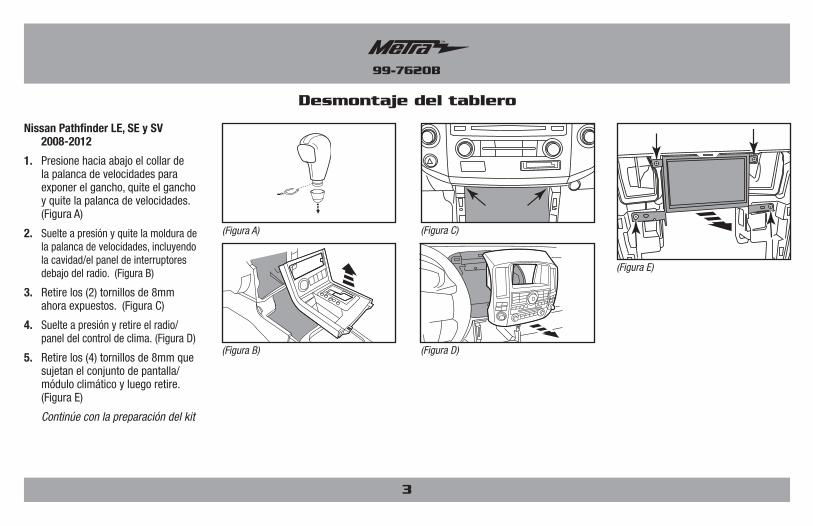
Desmontaje del tablero
Nissan Pathfinder LE, SE y SV 2008-2012
1. Presione hacia abajo el collar de la palanca de velocidades para exponer el gancho, quite el gancho y quite la palanca de velocidades. (Figura A)
2. Suelte a presión y quite la moldura de la palanca de velocidades, incluyendo la cavidad/el panel de interruptores debajo del radio. (Figura B)
3. Retire los (2) tornillos de 8mm ahora expuestos. (Figura C)
4. Suelte a presión y retire el radio/panel del control de clima. (Figura D)
5. Retire los (4) tornillos de 8mm que sujetan el conjunto de pantalla/módulo climático y luego retire. (Figura E)
Continúe con la preparación del kit
(Figura A)
(Figura D)(Figura B)
(Figura C)
(Figura E)
99-7620B
4
Preparación del kit
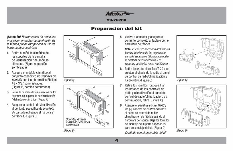
¡Atención! Herramientas de mano son muy recomendables como el guión de la fábrica puede romper con el uso de herramientas eléctricas.
1. Retire el módulo climático de los soportes de la pantalla de visualización / del módulo climático. (Figura A, porción sombreada)
2. Asegure el módulo climático al conjunto específico de soportes de pantalla con los (4) tornillos Phillips #8 x 3/8” suministrados. (Figura B, porción sombreada)
3. Retire la pantalla de visualización de los soportes de la pantalla de visualización / del módulo climático. (Figura A)
4. Asegure la pantalla de visualización al conjunto específico de brackets de pantalla utilizando el hardware de fábrica. (Figura B)
5. Vuelva a conectar y asegure el conjunto completo al tablero con el hardware de fábrica.
Nota: Puede ser necesario archivar los bordes interiores de los soportes de pantalla superiores (2) para acomodar la pantalla de visualización. Los soportes de fábrica no se reutilizarán.
6. Retire los (4) tornillos Torx T-20 que sujetan el chasis de la radio al panel de control de radio/climatización y luego retire. (Figura C)
7. Retire los tornillos Torx que fijan los botones de los controles de radio y climatización al panel de control de radio/climatización, y a continuación, retire. (Figura C)
8. Asegure el panel de control HVAC y los (2) paneles de control externos al panel de control de radio/climatización de fábrica usando el hardware de fábrica. Deje los tornillos de montaje de la parte superior (2) para ensamblaje del kit. (Figura D)
Continúe con el ensamble del kit
(Figura C)
(Figura D)
(Figura A)
(Figura B)
Soportes Armada mostrados con fines ilustrativos
99-7620B
Ensamble del kit
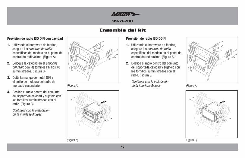
Provisión de radio ISO DIN con cavidad
1. Utilizando el hardware de fábrica, asegure los soportes de radio específicos del modelo en el panel de control de radio/clima. (Figura A)
2. Coloque la cavidad en el soportes del radio con (4) tornillos Phillips #8 suministrados. (Figura B)
3. Quite la manga de metal DIN y el anillo de moldura del radio de mercado secundario.
4. Deslice el radio dentro del conjunto del soporte/la cavidad y sujételo con los tornillos suministrados con el radio. (Figura B)
Continuar con la instalación de la interfase Axxess
Provisión de radio ISO DDIN
1. Utilizando el hardware de fábrica, asegure los soportes de radio específicos del modelo en el panel de control de radio/clima. (Figura A)
2. Deslice el radio dentro del conjunto del soporte/la cavidad y sujételo con los tornillos suministrados con el radio. (Figura B)
Continuar con la instalación de la interfase Axxess
5
(Figura B) (Figura B)
(Figura A) (Figura A)
99-7620B
• Conserva la pantalla de fábrica
• Retiene la cámara de reversa de fábrica
• Conserva la toma AUX-IN de fábrica
• Retiene las funciones de personalización
• Capacidad de añadir cámara de reversa de mercado secundario y entrada adicio
• Funciona en modelos amplificados o no amplificados
• Arnés ASWC-1 precableado (ASWC-1 se vende por separado)
CARACTERÍSTICAS DE LA INTERFASE
• Herramienta de corte
• Ponchadora
• Cinta
• Conectores (ejemplo: conectores de extremo, de campana, etc.)
HERRAMIENTAS REQUERIDAS• Interfase Axxess• Componentes LD-7620-MAIN: • Arnés 7620-MAIN • Arnés de 12 pins con conectores RCA • Interfase de 20-pin a 24-pin para mostrar el arnés• Componentes LD-7620-NAV: • Arnés 7620-NAV • Arnés de 32 pins con conectores RCA • Interfase de 20-pin a 12-pin para mostrar el arnés• 14 pins a 14 pins panel de control HVAC para conectar el arnés• 10 pins a 10 pins panel de control HVAC al (2) arnés del panel de control externo
COMPONENTES DE LA INTERFASE
Instalación de la interfase Axxess
Conexiones que se deben hacer Para modelos sin NAV de fábrica ..........................................................7-8 Para modelos con NAV de fábrica ...........................................................9Instalación del interfase ...........................................................................10Montaje final .............................................................................................11Operación de la pantalla .....................................................................11-14Actualización de la interfase ....................................................................14
Indice
6
99-7620B
Conexiones que se deben hacer (para modelos sin NAV de fábrica)
Arnés 7620-MAIN
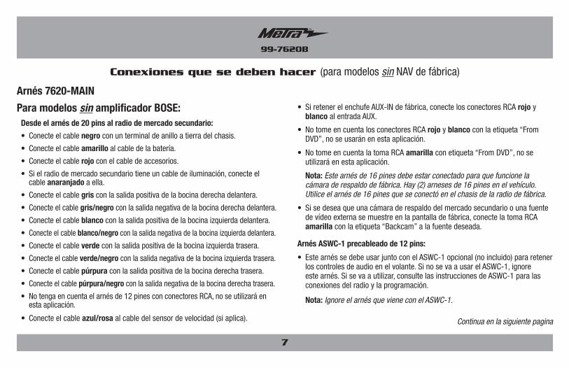
Para modelos sin amplificador BOSE: Desde el arnés de 20 pins al radio de mercado secundario:
• Conecte el cable negro con un terminal de anillo a tierra del chasis.
• Conecte el cable amarillo al cable de la batería.
• Conecte el cable rojo con el cable de accesorios.
• Si el radio de mercado secundario tiene un cable de iluminación, conecte el cable anaranjado a ella.
• Conecte el cable gris con la salida positiva de la bocina derecha delantera.
• Conecte el cable gris/negro con la salida negativa de la bocina derecha delantera.
• Conecte el cable blanco con la salida positiva de la bocina izquierda delantera.
• Conecte el cable blanco/negro con la salida negativa de la bocina izquierda delantera.
• Conecte el cable verde con la salida positiva de la bocina izquierda trasera.
• Conecte el cable verde/negro con la salida negativa de la bocina izquierda trasera.
• Conecte el cable púrpura con la salida positiva de la bocina derecha trasera.
• Conecte el cable púrpura/negro con la salida negativa de la bocina derecha trasera.
• No tenga en cuenta el arnés de 12 pines con conectores RCA, no se utilizará en esta aplicación.
• Conecte el cable azul/rosa al cable del sensor de velocidad (si aplica).
• Si retener el enchufe AUX-IN de fábrica, conecte los conectores RCA rojo y blanco al entrada AUX.
• No tome en cuenta los conectores RCA rojo y blanco con la etiqueta “From DVD”, no se usarán en esta aplicación.
• No tome en cuenta la toma RCA amarilla con etiqueta “From DVD”, no se utilizará en esta aplicación.
Nota: Este arnés de 16 pines debe estar conectado para que funcione la cámara de respaldo de fábrica. Hay (2) arneses de 16 pines en el vehículo. Utilice el arnés de 16 pines que se conectó en el chasis de la radio de fábrica.
• Si se desea que una cámara de respaldo del mercado secundario o una fuente de vídeo externa se muestre en la pantalla de fábrica, conecte la toma RCA amarilla con la etiqueta “Backcam” a la fuente deseada.
Arnés ASWC-1 precableado de 12 pins:
• Este arnés se debe usar junto con el ASWC-1 opcional (no incluido) para retener los controles de audio en el volante. Si no se va a usar el ASWC-1, ignore este arnés. Si se va a utilizar, consulte las instrucciones de ASWC-1 para las conexiones del radio y la programación.
Nota: Ignore el arnés que viene con el ASWC-1.
7
Continua en la siguiente pagina
99-7620B
8
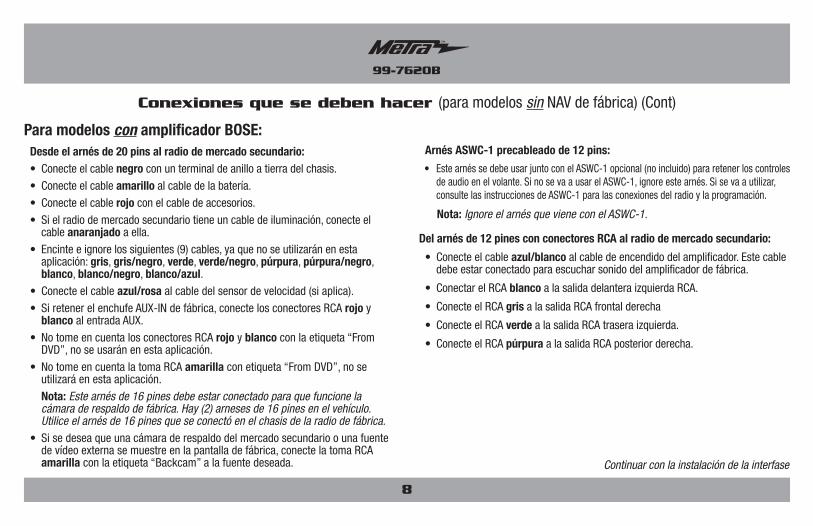
Conexiones que se deben hacer (para modelos sin NAV de fábrica) (Cont)
Arnés ASWC-1 precableado de 12 pins:
• Este arnés se debe usar junto con el ASWC-1 opcional (no incluido) para retener los controles de audio en el volante. Si no se va a usar el ASWC-1, ignore este arnés. Si se va a utilizar, consulte las instrucciones de ASWC-1 para las conexiones del radio y la programación.
Nota: Ignore el arnés que viene con el ASWC-1.
Del arnés de 12 pines con conectores RCA al radio de mercado secundario:
• Conecte el cable azul/blanco al cable de encendido del amplificador. Este cable debe estar conectado para escuchar sonido del amplificador de fábrica.
• Conectar el RCA blanco a la salida delantera izquierda RCA.
• Conecte el RCA gris a la salida RCA frontal derecha
• Conecte el RCA verde a la salida RCA trasera izquierda.
• Conecte el RCA púrpura a la salida RCA posterior derecha.
Para modelos con amplificador BOSE: Desde el arnés de 20 pins al radio de mercado secundario: • Conecte el cable negro con un terminal de anillo a tierra del chasis. • Conecte el cable amarillo al cable de la batería. • Conecte el cable rojo con el cable de accesorios. • Si el radio de mercado secundario tiene un cable de iluminación, conecte el
cable anaranjado a ella. • Encinte e ignore los siguientes (9) cables, ya que no se utilizarán en esta
aplicación: gris, gris/negro, verde, verde/negro, púrpura, púrpura/negro, blanco, blanco/negro, blanco/azul.
• Conecte el cable azul/rosa al cable del sensor de velocidad (si aplica). • Si retener el enchufe AUX-IN de fábrica, conecte los conectores RCA rojo y
blanco al entrada AUX. • No tome en cuenta los conectores RCA rojo y blanco con la etiqueta “From
DVD”, no se usarán en esta aplicación. • No tome en cuenta la toma RCA amarilla con etiqueta “From DVD”, no se
utilizará en esta aplicación.Nota: Este arnés de 16 pines debe estar conectado para que funcione la cámara de respaldo de fábrica. Hay (2) arneses de 16 pines en el vehículo. Utilice el arnés de 16 pines que se conectó en el chasis de la radio de fábrica.
• Si se desea que una cámara de respaldo del mercado secundario o una fuente de vídeo externa se muestre en la pantalla de fábrica, conecte la toma RCA amarilla con la etiqueta “Backcam” a la fuente deseada. Continuar con la instalación de la interfase
99-7620B
9
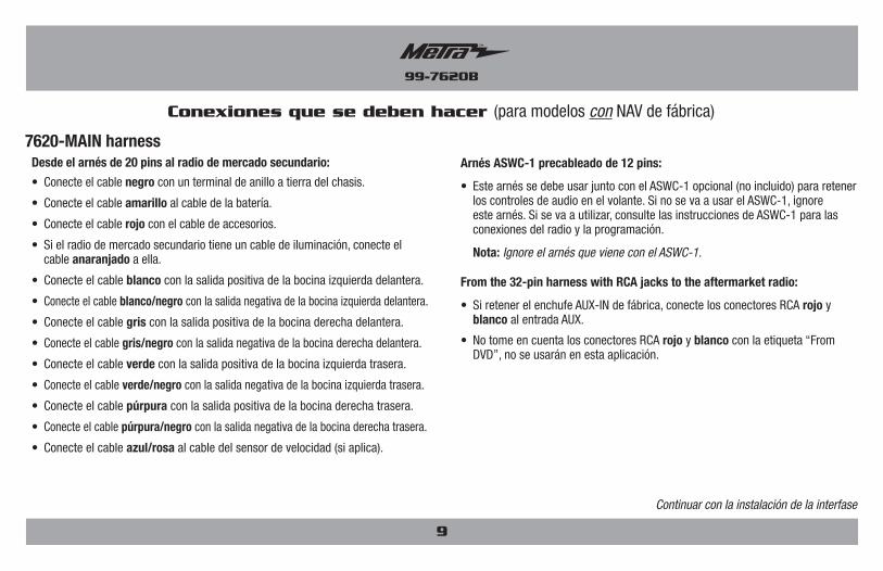
Conexiones que se deben hacer (para modelos con NAV de fábrica)
7620-MAIN harness Desde el arnés de 20 pins al radio de mercado secundario:
• Conecte el cable negro con un terminal de anillo a tierra del chasis.
• Conecte el cable amarillo al cable de la batería.
• Conecte el cable rojo con el cable de accesorios.
• Si el radio de mercado secundario tiene un cable de iluminación, conecte el cable anaranjado a ella.
• Conecte el cable blanco con la salida positiva de la bocina izquierda delantera.
• Conecte el cable blanco/negro con la salida negativa de la bocina izquierda delantera.
• Conecte el cable gris con la salida positiva de la bocina derecha delantera.
• Conecte el cable gris/negro con la salida negativa de la bocina derecha delantera.
• Conecte el cable verde con la salida positiva de la bocina izquierda trasera.
• Conecte el cable verde/negro con la salida negativa de la bocina izquierda trasera.
• Conecte el cable púrpura con la salida positiva de la bocina derecha trasera.
• Conecte el cable púrpura/negro con la salida negativa de la bocina derecha trasera.
• Conecte el cable azul/rosa al cable del sensor de velocidad (si aplica).
Arnés ASWC-1 precableado de 12 pins:
• Este arnés se debe usar junto con el ASWC-1 opcional (no incluido) para retener los controles de audio en el volante. Si no se va a usar el ASWC-1, ignore este arnés. Si se va a utilizar, consulte las instrucciones de ASWC-1 para las conexiones del radio y la programación.
Nota: Ignore el arnés que viene con el ASWC-1.
From the 32-pin harness with RCA jacks to the aftermarket radio:
• Si retener el enchufe AUX-IN de fábrica, conecte los conectores RCA rojo y blanco al entrada AUX.
• No tome en cuenta los conectores RCA rojo y blanco con la etiqueta “From DVD”, no se usarán en esta aplicación.
Continuar con la instalación de la interfase
99-7620B
10
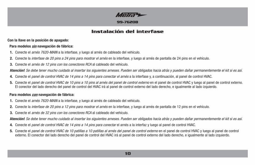
Con la llave en la posición de apagado:
Para modelos sin navegación de fábrica:
1. Conecte el arnés 7620-MAIN a la interfase, y luego al arnés de cableado del vehículo.
2. Conecte la interfase de 20 pins a 24 pins para mostrar el arnés en la interfase, y luego al arnés de pantalla de 24 pins en el vehículo.
3. Conecte el arnés de 12 pins con los conectores RCA al cableado del vehículo.
Atención! Se debe tener mucho cuidado al insertar los siguientes arneses. Pueden ser obligados hacia atrás y pueden dañar permanentemente el kit si es así.
4. Conecte el panel de control HVAC de 14 pins a 14 pins para conectar el arnés a la interfase y, a continuación, al panel de control HVAC.
5. Conecte el panel de control HVAC de 10 pins a 10 pins al arnés del panel de control externo en el panel de control HVAC y luego al panel de control externo. El conector del lado derecho del panel de control del HVAC irá al panel de control externo del lado derecho, e igualmente al lado izquierdo.
Para modelos con navegación de fábrica:
1. Conecte el arnés 7620-MAIN a la interfase, y luego al arnés de cableado del vehículo.
2. Conecte la interfase de 20 pins a 12 pins para mostrar el arnés en la interfase, y luego al arnés de pantalla de 12 pins en el vehículo.
3. Conecte el arnés de 32 pins con los conectores RCA al cableado del vehículo.
Atención! Se debe tener mucho cuidado al insertar los siguientes arneses. Pueden ser obligados hacia atrás y pueden dañar permanentemente el kit si es así.
4. Conecte el panel de control HVAC de 14 pins a 14 pins para conectar el arnés a la interfaz y luego al panel de control HVAC.
5. Conecte el panel de control HVAC de 10 patillas a 10 patillas al arnés del panel de control externo en el panel de control HVAC y luego al panel de control externo. El conector del lado derecho del panel de control del HVAC irá al panel de control externo del lado derecho, e igualmente al lado izquierdo.
Instalación del interfase

99-7620B
11
1. Localice el conector de antena de fábrica en el tablero y complete todas las conexiones necesarias a la radio. Metra recomienda utilizar el adaptador adecuado de Metra.
2. Antes de utilizar el kit debe ser inicializado.
Atención! Si la interfase pierde energía por cualquier razón, tendrán que volverse a ejecutar los siguientes pasos. Si va a utilizar el ASWC-1, conéctelo después de inicializar y probar el interfase/radio con la llave en la posición de apagado.
a. Gire la llave (o pulsar para botón de inicio) a la posición de encendido and y esperar hasta que la radio se enciende. La pantalla debe encenderse dentro de 30 segundos.
Nota: Si la pantalla no se enciende dentro, gire la llave a la posición de apagado, desconecte la interfase, compruebe todas las conexiones, vuelva a conectar la interfase, y vuelva a intentarlo. Asegúrese de que el arnés de la pantalla esté conectado.
b. Prenda su vehículo para probar que todo las funciones le estén trabajando bien antes de volver a montar el tablero.
Nota: Los controles del clima del asiento trasero (si procede) ya no funcionarán con este kit.
3. Asegure el conjunto completo en el salpicadero y, a continuación, vuelva a montar el salpicadero en orden inverso al desmontaje.
Montaje final
Todas las funciones del botón se mantienen y se controlan de la misma manera que los botones de fábrica fueron controlados. (ejemplo: Presión de los neumáticos, economía de combustible, brillo, ajuste del reloj, etc.)
Nota: Los 2 botones en blanco del panel de control HVAC no se utilizarán en esta aplicación.
Ajustes:
Operación de la pantalla
Continua en la siguiente pagina
99-7620B
12
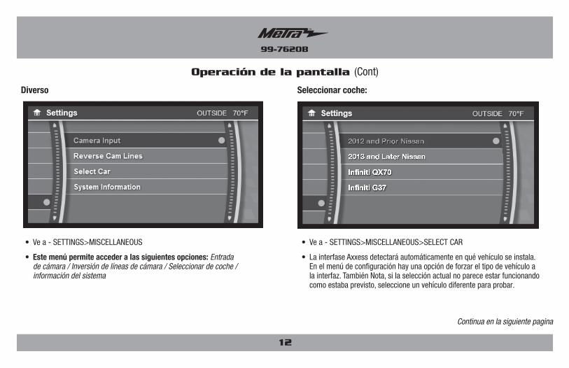
Operación de la pantalla (Cont)
• Ve a - SETTINGS>MISCELLANEOUS>SELECT CAR
• La interfase Axxess detectará automáticamente en qué vehículo se instala. En el menú de configuración hay una opción de forzar el tipo de vehículo a la interfaz. También Nota, si la selección actual no parece estar funcionando como estaba previsto, seleccione un vehículo diferente para probar.
• Ve a - SETTINGS>MISCELLANEOUS
• Este menú permite acceder a las siguientes opciones: Entrada de cámara / Inversión de líneas de cámara / Seleccionar de coche / información del sistema
Seleccionar coche:Diverso
Continua en la siguiente pagina

99-7620B
13
Operación de la pantalla (Cont)
Líneas De Cámara De Reversa:
Continua en la siguiente pagina
Entrada de la cámara:
• Ve a – SETTINGS> MISCELLANEOUS>CAMERA INPUT
• La cámara de reserva de fábrica continuará funcionando de forma predeterminada. No se requieren pasos adicionales .
• Si desea que se muestre una cámara de respaldo del mercado secundario en la pantalla de fábrica, seleccione “Aftermarket Backup Cam”.
• Sólo para modelos no NAV: Si desea visualizar una fuente de vídeo externa (AUX-VIDEO) en la pantalla de fábrica, seleccione “Backup Cam Disabled”.
• Para activar AUX-VIDEO, pulse el botón en blanco del controlador externo derecho. AUX-VIDEO sólo funcionará mientras el vehículo esté en el parque.
• Ve a – SETTINGS>MISCELLANEOUS> REVERSE CAM LINES
• Las líneas de cámara de reversa están desactivados de forma predeterminada.
• Activar para activar las líneas de cámara inversa; Desactivarlos para desactivarlos.
99-7620B
14
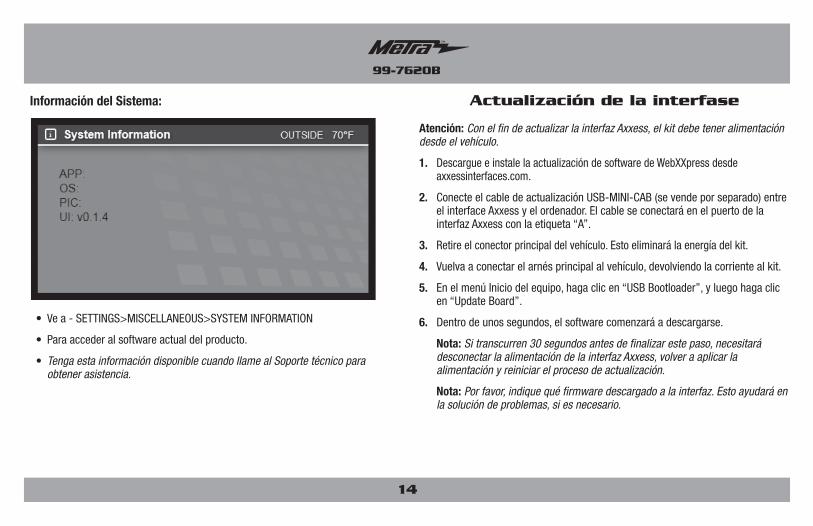
Atención: Con el fin de actualizar la interfaz Axxess, el kit debe tener alimentación desde el vehículo.
1. Descargue e instale la actualización de software de WebXXpress desde axxessinterfaces.com.
2. Conecte el cable de actualización USB-MINI-CAB (se vende por separado) entre el interface Axxess y el ordenador. El cable se conectará en el puerto de la interfaz Axxess con la etiqueta “A”.
3. Retire el conector principal del vehículo. Esto eliminará la energía del kit.
4. Vuelva a conectar el arnés principal al vehículo, devolviendo la corriente al kit.
5. En el menú Inicio del equipo, haga clic en “USB Bootloader”, y luego haga clic en “Update Board”.
6. Dentro de unos segundos, el software comenzará a descargarse.
Nota: Si transcurren 30 segundos antes de finalizar este paso, necesitará desconectar la alimentación de la interfaz Axxess, volver a aplicar la alimentación y reiniciar el proceso de actualización.
Nota: Por favor, indique qué firmware descargado a la interfaz. Esto ayudará en la solución de problemas, si es necesario.
Actualización de la interfase
• Ve a - SETTINGS>MISCELLANEOUS>SYSTEM INFORMATION
• Para acceder al software actual del producto.
• Tenga esta información disponible cuando llame al Soporte técnico para obtener asistencia.
Información del Sistema:
99-7620B
15
Notas
METRA - The World’s best kits ® metraonline.com © COPYRIGHT 2016 METRA ELECTRONICS CORPORATION
REV.
12/
8/20
16
INST
99-7
620B
KNOWLEDGE IS POWEREnhance your installation and fabrication skills by enrolling in the most recognized and respected mobile electronics school in our industry.Log onto www.installerinstitute.com or call 800-354-6782 for more information and take steps toward a better tomorrow.
Metra recomienda técnicos con certificación del Programa de Certificación en Electrónica Móvil (Mobile Electronics Certification Program, MECP).
EL CONOCIMIENTO ES PODERMejore sus habilidades de instalación y fabricación inscribiéndose en la escuela de dispositivos electrónicos móviles más reconocida y respetada de nuestra industria. Regístrese en www.installerinstitute.com o llame al 800-354-6782 para obtener más información y avance hacia un futuro mejor.
Instrucciones de instalación para la pieza 99-7620B
®
IMPORTANTESi tiene dificultades con la instalación de este producto, llame a nuestra línea de soporte técnico al 1-800-253-TECH. Antes de hacerlo, revise las instrucciones por segunda vez y asegúrese de que la instalación se haya realizado exactamente como se indica en las instrucciones. Por favor tenga el vehículo desarmado y listo para ejecutar los pasos de resolución de problemas antes de llamar.