nimbus a press kit
TRANSCRIPT

8/8/2019 Nimbus a Press Kit
http://slidepdf.com/reader/full/nimbus-a-press-kit 1/40
L - - --- -'}~~
NATIONAL AERONAUTICS AND SPACE ADMINISTRATION TELS WO 2-4155E, WASHINGTON, D.C. 20546 *WO 3-6925
> FOR RELEASE: SUNDAYAugust
9, 1964*RELEASE NO: 64-195
NIMBUS WEATHER
SATELLITE SCHEDULED
FOR LAUNCH
The largest experimental weather satellite ever built by the
United States is scheduled for its maiden flight by the National
Aeronautics and Space Administration from the Pacific Missile Range
in California no earlier than August 14.

8/8/2019 Nimbus a Press Kit
http://slidepdf.com/reader/full/nimbus-a-press-kit 2/40
-2- Q
Eva1hat.v '.- AdvaXncd Vidicon Camera System (AVCS) for
tapa storare and readout of global cloud pictures during
daylight.
Provide improved Dictures of local clouds by means of the
Nimbus Automatic Picture Transmission (APT) system.
Evaluate the High Resolution Infrared Radiometer (HRIR)
system to map global night-time cloud cover.
The stabilization system, to orient the spacecraft sensors for
viewing the Earth vertically, the power system to operate the instru-

8/8/2019 Nimbus a Press Kit
http://slidepdf.com/reader/full/nimbus-a-press-kit 3/40
- - ' - - --
-3-
This control system -- plus a near-polar orbit -- permits
Nimbus to look at Earth's entire 200 million square-mile-area
every day,
If the Thor-Agena-B launch vehicle successfully places Nimbus
into orb.t, the cameras and the infrared sensors in the satellite
will view the Earth from some 575-statute miles high, providing
continuous cloud pictures during each 14-orbit day.
In contrast, the spin-stabilized TIROS satellites view about 20-
25 per cent of the Earth each day.

8/8/2019 Nimbus a Press Kit
http://slidepdf.com/reader/full/nimbus-a-press-kit 4/40
-4 0:
The Infrared ra.La tIon is modulated and recorded on a tape
recorder and then transmitted to a ground station. A facsimile system
reconstitutes the pictures and provides a cloud picture with a
resolution of five miles. The cloud pictures will be of a quality
comparable to present TIROS pictures.
The Automatic Picture Transmission (APT) system was designed
for Nimbus and successfully tested on TIROS VIII last December. It
takes real-time pictures which are'sent immediately to relatively
simple APT ground stations scattered around the globe. The camera

8/8/2019 Nimbus a Press Kit
http://slidepdf.com/reader/full/nimbus-a-press-kit 5/40
O-5--
AVCS pictures can be transmitted directly to one of two Command
and Data Acquisition (CDA) stations, when the satellite is within
line-of-sight-range of the station. Pictures taken of other parts of
the Earth are stored on a tape recorder and will be transmitted on
command.
CDA stations are at Gilmore Creek, Alaska and Rosman, N.C. Both
of the stations use 85-foot diameter antennas to receive weather data.
The Alaskan station will acquire the spacecraft an average of 10 of
the 14 orbits each day. The North Carolina station will acquire an
average of two orbits a day of the four missed on the Alaskan station.

8/8/2019 Nimbus a Press Kit
http://slidepdf.com/reader/full/nimbus-a-press-kit 6/40
- 6- - . - b-
.l4 6
Pictures from :um.bus al11 not be transmitted until it has been
determined that all spacecraft subsystems are working properly. The
operational plan is to turn on eacn system in a series of steps,
and then command the satellite to start taking pictures.
If the spacecraft performs as planned the first APT pictures
will be taken and read-out at Goddard at approximately 12:45 p.m.
(EDT) on the day of launch.
During the sixth orbit, about 2:30 p.m. (EDT), the satellite
will send AVCS pictures of the Eastern United States to the NASA
North Carolina station for immediate microwave transmission to Goddard.

8/8/2019 Nimbus a Press Kit
http://slidepdf.com/reader/full/nimbus-a-press-kit 7/40
-7-
: 'U 2 has been put through the most severe test program of
any unmanlmed satellite built to date. Testing included extreme
shaking of a Nimbus prototype from five cycles to 2000; centrifuge
teats with loads up to 15 Gs (15 times the pull of gravity) and
cycling in the thermal vacuum chamber of heat and cold for several
weeks.
Then during the summer of 1962, nuclear testing created an
artificial radiation belt in the area where the satellite would later
orbit. As a result, solar cells on the spacecraft were replaced by
a new type havihg more resistance to radiation damage.

8/8/2019 Nimbus a Press Kit
http://slidepdf.com/reader/full/nimbus-a-press-kit 8/40
-8-
i VLbJUS BACKGROUND INFORMATION
August 1964 Launch Pacific Missile Range
ContentsTitle Page
TECHNICAL INFORMATION . . . . . ... . . . . . 7
Nimbus Spacecraft . . . . . . ... . . . . . . 9
Attitude Control Sub-System . . . . . . . . . 9
Power Supply . . . . . . . . . . . . . . . . . 11
Advanced Vidicon Camera System . . . . . . . . 12
Automatic Picture Transmission Camera . . . . . 14
High Resolution Infrared Radiometer (HIUR) . . 16

8/8/2019 Nimbus a Press Kit
http://slidepdf.com/reader/full/nimbus-a-press-kit 9/40
O-9
Nimbus SDacecraft
4 1The
Nimbus spacecraft includes an upper attitude control section
built by General Electric Co., the lower sensory section, and an
interconnecting truss structure. The spacecraft stands 10 feet tall
and weighs 830 pounds.
The truss structure connects the upper hexagonal control section
and the sensory housing or ring at three points. It provides the
critical alignment required between the two sections.
Weather sensing equipment and associated electronics are housed

8/8/2019 Nimbus a Press Kit
http://slidepdf.com/reader/full/nimbus-a-press-kit 10/40
-10- 4
attitude-control ecbsystems, and provides unobstructed exposed
mounting for the Sun sensors, horizon scanners, control nozzles,
and the command antenna. Two large solar paddles, 8 feet tall by
2.75 feet wide, attach to control shafts projecting from the control
housing and contain 10,500 solar cells.
Primary requirements of the control subsystem are to orient
and stabilize the spacecraft with respect to the Earth and the
orbit plane, and the solar paddles with respect to the Sun.
Nimbus' control subsystem uses two infrared horizon scanners,

8/8/2019 Nimbus a Press Kit
http://slidepdf.com/reader/full/nimbus-a-press-kit 11/40
, ~-11.-
: Power Supply
To operate a large spacecraft like Nimbus fo r extended periods
requires a tremendous amount of power as compared to the smaller,
frst-gene-ation satellites.
! During periods of full solar illumination, the initial solar
array power output is 450 watts. The average power output for all
spacecraft requirements is 250 watts.
Major components of the Nimbus power supply, which deliver minus
24.5 volts regulated within plus or minus two per cent, are an array

8/8/2019 Nimbus a Press Kit
http://slidepdf.com/reader/full/nimbus-a-press-kit 12/40
-12-
To help lower the operating temperatures of the cells, a red-
blue filter rejects that portion of the spectrum in which the cells
are insensitive.
The expected average paddle-operating temperature is approximately
plus 100 degreesFahrenheit with extremes ranging from a minus 176
degrees to plus 140 degrees.
The Nimbus storage batteries are packaged into seven parallil-
connected modules, each consisting of 23 series-connected nickel
cadmium cells. Each cell has a 3.2 ampere-hour capacity with a mini-
mum terminal voltage, at discharge, of 1.15 volts.

8/8/2019 Nimbus a Press Kit
http://slidepdf.com/reader/full/nimbus-a-press-kit 13/40
-
-'-.
If O -13-
I7V cameras deployed, n a fan-like array to produce a three-segment
composite picture.
Each camera covers a 37-degree field-of-view with th e center
camera pointing straight down (local vertical). The optical axis
of the second and third units are rotated 35 degrees to the right
and left of local vertical. This arrangement produces a composite picture
providing the lateral field-of-view (with two degree overlap) necessary
to cover the 26-degree rotation of the Earth between spacecraft passes.
The three-strip picture from the AVCS picture will show an area of

8/8/2019 Nimbus a Press Kit
http://slidepdf.com/reader/full/nimbus-a-press-kit 14/40
The TV tubes in the advanced vidicon cameras are 800-scan-
line, 1-inch-diameter vidicons giving a linear resolution of about
one-half mile at the optical center at an altitude of 575 statute
miles.
For storing pictures for playback later, the AVCS has a tape
recorder with 1200 feet of tape to record two complete orbits of
192 pictures. A limit switch stops the recorder when the tape is
filled to capacity.
A full two orbits of pictures can be sent from the spacecraft

8/8/2019 Nimbus a Press Kit
http://slidepdf.com/reader/full/nimbus-a-press-kit 15/40
to -15-
A timer in the APT subsystem programs the equipment for
continuous cycles of prepare and expose during the first eight
ISecondsf each 208-second picture cycle. The remaining 200 seconds
is used to read out the photographs at ground stations at a scan
rate of four lines per second.
Four major elements make up the APT subsystem in the spacecraft:
the sensory housing which contains the camera; vidicon and vidicon
electronics; a video electronic module consisting of a video detector
and timing and switching circuitry; power converters and an FM
transmitter using the 136.9 megacycle frequency.

8/8/2019 Nimbus a Press Kit
http://slidepdf.com/reader/full/nimbus-a-press-kit 16/40
-16-
H rrh Rezolution Infrared Radiometer
So meteorologists can receive nighttime weather information,
a High Resolution Infrared Radiometer made by International Telephone
and Telegraph Co., is installed in Nimbus. This operates for approxi-
mately 40 minutes during each orbit.
The highly sensitive HRIR, weighing about 12 pounds, will map
nighttime cloud cover by measuring the energy received in a narrow
spectral range (3.4 - 4.2 microns).
In contrast to television the HRIR forms no image. Cloud-

8/8/2019 Nimbus a Press Kit
http://slidepdf.com/reader/full/nimbus-a-press-kit 17/40
-17-
From an altitude oL 575 miles the HRIR has an instantaneous
field of view of 8.6 milliradians which corresponds to a linear
resolution of five miles below the vertical.
The radiometer output is fed to a FM modulator and then to a
tape recorder which is similar to the AVCS tape recorder. At the
* same time a 10-kc time signal is placed on the tape from a clock in
the spacecraft. The recorder accepts data at a tape speed of 3.75 inches
j per second.
A multiplexer receives the recorded information and the infrared

8/8/2019 Nimbus a Press Kit
http://slidepdf.com/reader/full/nimbus-a-press-kit 18/40
- -a-- -
-18-°
The clock usez a crystal-stabilized oscillator which provides
absolute time determination to relate the orbital location of the
spacecraft to its geographical position. The 800-kc aged crystal is
sealed in glass and maintained at a constant temperature by a heating
coil which provides accurate timing reference.
Nimbus receives command signals from the Data Acquisition
Facilities (DAF) ground stations in North Carolina or Alaska through
a whip antenna mounted on top of the attitude control section.
The command receivers reproduce the code generated by the DAF

8/8/2019 Nimbus a Press Kit
http://slidepdf.com/reader/full/nimbus-a-press-kit 19/40
0 . -19-
Ieat and cold are controlled in the sensory ring and control
section by pneumatically activated shutters on the outside of the
two sections. These shutters open and close automatically.
Telemetry Subsystem
Nimbus uses a pulse code modulation (PCM) telemetry system,
designed by Radiation, Inc., for transmitting information via a
transmitter through a phased array antenna to the ground stations. The
PCM/A4 transmitter is built by Hughes Aircraft Co.
One mode provides stored data, on a Raymond Engineering tape

8/8/2019 Nimbus a Press Kit
http://slidepdf.com/reader/full/nimbus-a-press-kit 20/40
-20-
This Centier, operated by General Electric personnel under
contract to NASA, evaluates spacecraft performance and determinesall
of the commands to be sent to the spacecraft from Rosman, N.C. and
Gilmore Creek, Alaska.
Functions of the NTCC are:
. Prepare all spacecraft command sequences.
. Perform6 continuing analysis of key spacecraft parameters.
. Determine corrective action in case of spacecraft subsystemmalfunction.
. Specify the sequence of system data processing.

8/8/2019 Nimbus a Press Kit
http://slidepdf.com/reader/full/nimbus-a-press-kit 21/40
-21-
"Bonai WJeath'er Satellite Center
:;ill1 nadzc, wsasc.mL-nate, ao.- c:'ch.1ive tIl, cloud data used for
cocIat ocual mcteorological purposes.
The antennas at the Rosman and Gilmore sites are identical.
TIho surface of the large antennas consists of a double-curved
aluminum sheet panels which are separatedfrom
thereflector structure
to permit independent adjustment.
The antennas have a gain of approximately 50 db at 1700 mc, with
a -bea:-xid'tih of 0.6 degrees. At 136 me, the antennas have a gain of
8/8/2019 Nimbus a Press Kit
http://slidepdf.com/reader/full/nimbus-a-press-kit 22/40
-22-
One z ax t the Gmc. C:reck site and the other is at Goddard.
The Gilmore IDMI organi1zation will be manned by four 12-man teams
around the clock. Each team will consist of the following:
. One data operations supervisor,
. One AVCS/HRIR engineer,
. Two AVCS/HRIR technicians,
. One spacecraft systems engineer,
Ile meteorological analyst,
Two computer programmers,
One commBared console operator,

8/8/2019 Nimbus a Press Kit
http://slidepdf.com/reader/full/nimbus-a-press-kit 23/40
-a
~ j) Tho Lzequenlc~ for zerndx~n- meteorological data from. Timbuz to
the r-rou~nd isas 2~ollo-ao: Zrnmediately after the satellite has been
acquired, the sat-ellite's S-band transmitter is turned on by command
from the ground.
After 45 seconds of S-band warmup, the spacecraft begins sendingI VCS and HRIR stored weather data.
I1-IHRIR data are recorded on two tape recorders at the ground
i station, processed on-line, and recorded on 70mmn filmstrip.
Approximately 20 minutes is required for photographic processing before
3 the HRIR film data are ready for review.

8/8/2019 Nimbus a Press Kit
http://slidepdf.com/reader/full/nimbus-a-press-kit 24/40
'1 -24 1
"iimpJlicityand real-time pictures make the Automatic Picture
Transiissilon camera extremely appealing to the local weatherman
A typr..l'. c ground station, manufactured by Fairchild Stratos, Inc.,
consists of. manually tracked 13 db helix antenna (about 12-feet long),
a commercially available radio receiver, and a standard facsimile
machine. The 800-line APT picture and 0.25 scanning time per line
are comparable with standard 240 rpm facsimile equipment.
APT pictures are sent to the ground by a five-watt transmitter,
8/8/2019 Nimbus a Press Kit
http://slidepdf.com/reader/full/nimbus-a-press-kit 25/40
-25-
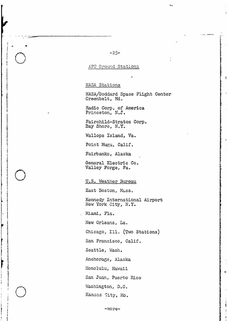
APr2 Grou-ond Stations
NASA Stations
NASA/Goddard Space Flight CenterCreenbelt, Md.
Radio Corp. of AmericaPrinceton, N.J.
Fairchild-Stratos Corp.Bay Shore, N.Y.
Wallops Island, Va.
Point Mugu, Calif.
Fairbanks, Alaska

8/8/2019 Nimbus a Press Kit
http://slidepdf.com/reader/full/nimbus-a-press-kit 26/40
-26- 0
M-Wnna-ional Participation
IO7, Caloba ObservatoryBombay, India
Centre D'etudes Meteorologigues SpatialeLannion, France
* National Research CouncilOttawa, Ontario, Canada
* Meteorological OfficeBrachnell, Berkshire, England
* Offenbach Am MainFederal Republic of Germany
* Danish Meteorological InstituteCopen1bagen, Denmark
* Department of InteriorMelbourne, Australia

8/8/2019 Nimbus a Press Kit
http://slidepdf.com/reader/full/nimbus-a-press-kit 27/40
-27-
1'a'lalS .prt Forces AntarcticaC r I;cu-.- cI, New ZealandU.'.-. * 3arato,,a
U. S. Army
U.S. Army Electronics R&D LaboratoryFort Monmouth, N.J.
U.S.A.F. Air Weather Service
L. G. Hanscom FieldBedford, Mass.
Offutt AFBOmaha, Neb.
Ent AFB, Colo.
Langley AFB, Va.

8/8/2019 Nimbus a Press Kit
http://slidepdf.com/reader/full/nimbus-a-press-kit 28/40
'a'hr quadron, Tan-Son-irhut, Viet Nam
'Joather lng,, Patrick AFB, Fla.
Private Users
* Univer3ity of WisconsinMadison, Wis.
* VLAC-TVNashville, Tenn.
* RCA Victor Co.
Montreal, Canada
* California Computer Products, Inc.Anaheim, Calif.
* Built their own stations.

8/8/2019 Nimbus a Press Kit
http://slidepdf.com/reader/full/nimbus-a-press-kit 29/40
-29-
. ors Roc-:ctdt-ncd engine will burn for 148 seconds. The
rocket will continue its flight powered by the vernier engines
which position tha vehicle in response to signals from the ground.
* At the desired altitude and velocity, about 157 seconds after
launch, the vernier engines cut off and a 33-second coast period
begins before Agena fires.
l1 The upper-stage Agena-B, which is 20 feet long and five feet in
diameter, made by Lockheed Missiles and Space Co., has a two-burn
i1 capability. The launch time is restricted by the "high-noon"

8/8/2019 Nimbus a Press Kit
http://slidepdf.com/reader/full/nimbus-a-press-kit 30/40
-30- *0j:
At 190 seconds after launch, Agena fires for the first time,
and five secondslater a programmed signal jettisons the protective
shroud which covers the spacecraft ejecting it out into space. 4
The shroud is 19 feet high and resembles a giant-clam shell.
Approximately 237 seconds after Agena ignites, the engine will
shut down and the entire Agena vehicle and spacecraft will coast from
100 miles high to 575 miles. At this altitude Agena will fire for
three seconds and kick the Nimbus into a circular near-polar, 575
statute miles orbit.

8/8/2019 Nimbus a Press Kit
http://slidepdf.com/reader/full/nimbus-a-press-kit 31/40
I FZ-)-31-
FOllowIfln APgena second burn shutdowns the vehicle is stabilized
by the Arena control system. The Agena horizon scanners are then
turned off, and an 80-degree pitch-up maneuver is executed at a
rate of one degree per second.
Explosive boltcutters or. the V-band separation clamp securing
the spacecraft to the adapter are ignited 112 seconds after the
second burnout and the spacecraft and Agena are separated.
Calibrated separation springs provide a separation velocity
of four feet per second. The delay in separation eliminates the

8/8/2019 Nimbus a Press Kit
http://slidepdf.com/reader/full/nimbus-a-press-kit 32/40
Launch ti..e changos w:itnh solar declination and is shown in
the following table:
Date Onens Optimum Closes
August
12-14 4:04 a.m. 4:38 a.m. 5:12 a.m.
15-17 4:03 a.m. 4:37 a.m. 5:11 a.m.
18-19 4:02 a.m. 4:36 a.m. 5:09 a.m.
20-22 4:01 a.m. 4:35 a.m. 5:08 a.m.
23-24 4:00 a.m. 4.33 a.m. 5:07 a.m.

8/8/2019 Nimbus a Press Kit
http://slidepdf.com/reader/full/nimbus-a-press-kit 33/40
0 D
-33-
propulsion Roclkctdyne main Bell mlain enginenCsine arnd two verniers
guidancc autopilot for first Minneapolis Honeywell90 seconds of flight inertial reference arnd
| then ground controlled Barnes horizon sensor
Bell Telephone Lab.system
diameter 8 feet 5 feet
contractor Douglas Aircraft Co. Tockheed Missile andSanta Monica, Calif. Space Co., Sunnyvale,
Calif.
Total lift off weight with Nimbus spacecraft: 123,681 pounds

8/8/2019 Nimbus a Press Kit
http://slidepdf.com/reader/full/nimbus-a-press-kit 34/40
-34-
J. I. oimsendc is Assistant Director, Space Sciences and
Satellite Applications. William G. Stroud is Chief, Aeronomy and
Meteorology Division. Nimbus Project Manager is Harry Press.
Joseph 3. Schwartz is Goddard Range Operations and Support Officer,
Point Arguello, Calif.
Vehicle systems management is under NASA's Lewis Research Center,
Cleveland, Dr. Abe Silverstein is Center Director. Dr. S. C. Himmel,
Agena Project Manager and Paul C. Winslow, Jr., Agena Project Engineer.
Launch of Nimbus is, by the U.S. Air Force 6595th Aerospace Test
Wing under technical supervision of GSFC. Col. Roy
8/8/2019 Nimbus a Press Kit
http://slidepdf.com/reader/full/nimbus-a-press-kit 35/40
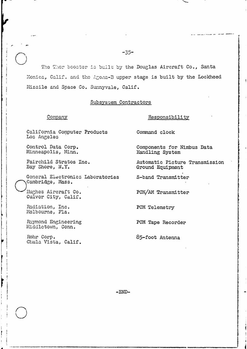
TWe :-cr boo.ctr Ad bu-2Ic by the Douglas Aircraft Co., Santa
Mcnica, Calif. and the f"c-na-B upper stage is built by the Lockheed
Iissile and Space Co. Sunnyvale, Calif.
Subsystem Contractors
Company Responsibility
California Computer Products Command clockLos Angeles
Control Data Corp. Components for Nimbus Data
Minneapolis, Minn. Handling System
Fairchild Stratos Inc. Automatic Picture Transmission
Bay Shore, N.Y. Ground Equipment

8/8/2019 Nimbus a Press Kit
http://slidepdf.com/reader/full/nimbus-a-press-kit 36/40
ROTATION~
SPACECRAFT S
XSECOND ORBIT
- -U I PAYs
s'-CONDI2 O'fDIT

8/8/2019 Nimbus a Press Kit
http://slidepdf.com/reader/full/nimbus-a-press-kit 37/40
'4- -
/V

8/8/2019 Nimbus a Press Kit
http://slidepdf.com/reader/full/nimbus-a-press-kit 38/40
APTPICTURE
.. .... . e.<\ .... ROUND STATIONS RDIN
.:COMMA-ND AND.'DATA ACOUISITION ..
COTRLUNTD DINTEGRATION METEOROLOGICALTV AND RADIA1ON DATA R OSERVATIONS
NGNENGODA~RDTDDT
EMERGENCY DAAA SPACEFLIGHT--- ----- JCENTERr
TELEV190ON SPCCAT AND HRIR - w- X>ATCA DHAA DTA DATA NEPHANALYSIS MAP S1ORM IDENTIFICATIONM
rI
ARCHIVAL
SCIENTIFIC AND ECHN - WEATHER
R EC OR D SCENTER
SNOW & ICE MAP |
- Nimbus Program Data Flow
00
0-

8/8/2019 Nimbus a Press Kit
http://slidepdf.com/reader/full/nimbus-a-press-kit 39/40

8/8/2019 Nimbus a Press Kit
http://slidepdf.com/reader/full/nimbus-a-press-kit 40/40
ATTITUDE COUSTROL HOUSING
COERMOL SCSH1ER
TELEMETRYNTNN eTEtN aTIAN
SOLAR PADDLE a n y SCAMERA
COARSE SUiWENSORSOLAR PADDLE
SUN SENSORYAW 14OZZLES
PNEUMATIC TANtK
SOLAR PADDLE
INTERCONNECTING TRUSS-
THERMAL CONTROL SHUTTERS
BEACON AND P1,,
TELEMETRY ANTENNAS-DAND ANTENNA
HIGH-RESOLUTION AC AEA
IN~FRARED RECORDERAVSRCDE
HIGH-RESOLUTIOrN INFRARED RADIOWETER
ATATAUTOMAT!S DVCECTIO-J, INORBIT
PICTURE-TRA!4SSAISSIO4 ANTENNA PICTURE*TRAHSMISSION CA -RA
-Nimbus A( ecraft