nicoletone - mplusmedtech.com
TRANSCRIPT


LONG TERM MONITORING NEURODIAGNOSTIC SYSTEMNicoletOne™
HIGH QUALITY AMPLIFIERS• Smallest LTM amplifier on the market• Record 32 or 64 channels or be combined
for up to 128 channels• NicoletOne drawing algorithm displays every
data point to eliminate screen aliasing• Provides more accurate data to
allow for improved diagnosis
NICOLETONE TRENDS• Compressed view of long EEG recordings
available - see the entire recording at a glance• Can be individually tuned and displayed• Greatly enhance traditional spike and
seizure detection
NICVUE• Complete patient management across
all Nicolet products• Save time with One-Button archiving
GRID-STRIP EDITOR• Predefined grid/strip layouts• Edit grid/strip as a whole or individual
electrodes as needed• Automatic creation of Sensor list• Automatic Amplifier Channel Assignment• Automatic creation of Reference Montage
EDIT PREVIEW• Trim down the EEG file before archiving• Customizable templates• Save time by previewing events before editing• Auto-save up to five minutes before and after an event
CENTRAL MONITORCentral Monitor allows 4 beds to be shown on one monitior screenallowing the patients to be watched at the nurses station.
REMOTE REVIEWThe Remote Review option makes it possible to review live studies -even more than one recording at a time - from the same remote reviewstation. It gives access to patient recordings taking place where itmight not be practical to accommodate additional observers.
REMOTE CONTROLThe Remote Control option goes a step further than Remote Review byallowing the user to control what is actually being recorded to disk onthe acquisition station. Remote Control also provides all thefunctionality of the acquisition program on the review station.
CENTRAL MONITOR STATION

Nicolet® CSC64 OR AmplifierNicolet® CSC64 OR/SSU Amplifier
P/N 169-443000 Rev02
Natus Neurology Incorporated 3150 Pleasant View RoadMiddleton, WI 53562 USATel: 1-800-356-0007 1-608-829-8500Fax: 1-608-829-8709www.natus.com
Specifications subject to change without notice.
© 2014 Natus Medical Incorporated. All Rights Reserved. All product names appearing on this document are trademarks or registered trademarks owned, licensed to, promoted or distributed by Natus Medical Incorporated, its subsidiaries or affiliates.
General SpecificationsDimensions ............................. 154mm (L) x 146mm (W) x 49mm (D) - C64 OR/SSU modelDimensions ................................... 115 mm (L) x 76 mm (W) x 45 mm (D) - C64 OR modelWeight ........................................................................................................Less than 1 KgOperating Environment (in use)Temperature ..........................................................................15.6 to 32.2° C, (60 to 90° F)Relative Humidity ........................................................................ 20-80%, non-condensingAltitude .............................................................................................. 0-3km, (0-10,000 ft)Non-Operating Environment (in storage)Temperature .............................................................................17.7 to 55° C, (0 to 132° F)Relative Humidity ........................................................................ 10-90%, non-condensingAltitude ............................................................................................ 0-12km, (0-40,000 ft)
Amplifier Analog/Digital Converter ............................................................... 22 bits (16 bits stored)ADC Resolution Voltage ......................................................................................0.153 µVChannels (Inputs) ............................................................................................64 channels DC Offset Tolerance ........................................................................................... ± 600 mVMaximum Input Range ......................................................................................... ± 5 mVBandwidth .....................................................................................................1.6 - 500 HzNoise ........................................................................................≤ 2µV pk-pk @ 1.6 - 70 HzInput Impedance ................................................................................................>100 MΩCMRR at Patient Inputs 110 dB (typical) at 1.6 – 70 Hz with active patient ground connectedNOTE: The following are under software control:Anti-aliasing Filter Cut-off Frequencies .........................................33, 67, 134 and 268 HzAmplifier Sample Rate ............................................................128, 256, 512 and 1024 Hz Software sub-sampling for individual channels Sensitivity 10, 20, 30, 50, 70, 100, 150, 200, 300, 500, 700, 1000, 2000, 5000 µV/cm 1, 2, 3, 5, 7, 10, 15, 20, 30, 50, 70, 100, 200, 500 µV/mmHigh Filters .........................10, 15, 25, 30, 35, 40, 50, 60, 70, 100, 150, 200, 300, 500 HzLow Filters ................................................................................................... 1.6, 2, 3, 5 HzNotch Filter .........................................................................................................50/60 HzRF Patient ProtectionRF Input Filter .................................................................................................... >500 KHz
Bipolar InputsNumber of Inputs. .................................. All odd channels: 32/64 inputs can be configuredas Bipolar AC in pairs of two through softwareMaximum Input Range ..................................................................................... ±5 mV ACBandwidth .............................................................................................1.66 – 500 Hz ACADC Resolution. ............................................................................................ 0.153 μV AC
Auxiliary Inputs4 Hi-level, non-isolated inputs (AI-1, AI-2, AI-3, AI-4) for connection of external devices (e.g. SpO2, CO2 monitors, etc.)Analog/Digital Converter ............................................................... 22 bits (16 bits stored)Maximum Input Range ......................................................................................... ± 2.5 VADC Resolution .....................................................................................................76.3 μVBandwidth .................................................................................................... DC – 500 Hz
Quality SystemManufactured, designed, developed and marketed under ISO 13485 certified quality system
Compliance/Regulatory StandardsDesigned, tested, manufactured and certified to meet the following domestic (USA), Canadian, European and International Standards:UL 60601-1 Medical Electrical Safety Standard (USA)CAN/CSA-C22.2 no. 601.1-M90 Medical Electrical Safety Standard (Canada)EN/IEC 60601-1 Medical Electrical Safety of Medical Equipment (International and Europe)IEC 60601-2-26 Particular Safety of electroencephalographs equipmentIEC 60601-2-40 Particular Safety of electromyography and evoked response equipmentEN 60601-1-2 Collateral safety standard for EMCEuropean Community (CE Mark) Medical Device Directive (MDD) product certified to comply to EC Directive 93/42/EEC Patient Isolation ............................................................................................................ BF
Technical Specifications
Ad
dit
ion
al In
form
atio
n a
nd
Saf
ety
Ref
eren
ce G
uid
e
Natus Neurology Incorporated
Additional Information and SafetyReference Guide
September 25, 2013
269-594705 Rev 11
© 2013 Natus Medical Incorporated or one of its subsidiaries. All rights reserved.Natus is a registered trademark of Natus Medical Incorporated. All product names appearing on this document are trademarks or registered trademarks owned, licensed to, promoted or distributed by Natus Medical Incorporated, its
subsidiaries or affiliates. All other trademarks are the property of their respective owners.


Additional Information and Safety Notes
Manufacturer........................................................................................................................................................ 2European Authorized Representative ................................................................................................................. 2CE Mark................................................................................................................................................................. 2Technical support .................................................................................................................................................. 2Safety Summary..................................................................................................................................................... 3U.S. Patents ............................................................................................................................................................ 3Service manuals for your system.......................................................................................................................... 4Specifications Nicolet Brand systems................................................................................................................... 5Ergonomic environment responsibilities............................................................................................................. 5Preventive maintenance ........................................................................................................................................ 6Cleaning, disinfection and sterilization of parts in contact with the patient ................................................... 7Safety notes............................................................................................................................................................. 9
General safety notes ......................................................................................................................................... 9Electrical shock (line voltage)........................................................................................................................ 12Data misinterpretation, corruption, loss, false positives, false negatives, etc. ............................................... 13Physical injury................................................................................................................................................ 15Amplifier arm................................................................................................................................................. 15Electrodes and transducers ............................................................................................................................. 15Electrical stimulators for Nicolet EDX, Nicolet Endeavor, Nicolet VikingSelect, Nicolet VikingQuest, Ultra-Pro S100 and Synergy Plinth and PIU ........................................................................................................... 17Auditory stimulator for Nicolet EDX, Nicolet Endeavor, Nicolet VikingSelect, Nicolet VikingQuest, Ultra-Pro S100 and Synergy Plinth ......................................................................................................................... 18Bovie / Electrocautery.................................................................................................................................... 19Implant electrodes .......................................................................................................................................... 20EMG ............................................................................................................................................................... 20Leakage current .............................................................................................................................................. 20Batteries.......................................................................................................................................................... 21Recycling / disposal ....................................................................................................................................... 21Defibrillation .................................................................................................................................................. 22Mains operated equipment with additional power supply ............................................................................. 22Replacement of fuses and other parts............................................................................................................. 22Hard drive....................................................................................................................................................... 22Restricted environmental conditions for operation, transport and storage..................................................... 23Electrodes and Amplifiers .............................................................................................................................. 24Isolation / Isolation transformer ..................................................................................................................... 25Software ......................................................................................................................................................... 26Electromagnetic Compatibility (EMC) Information ...................................................................................... 27ESD handling ................................................................................................................................................. 28Networking..................................................................................................................................................... 29Operating environment................................................................................................................................... 30System connections ........................................................................................................................................ 31
9/25/13 1

Natus Neurology Incorporated
Product Specific Cautions and Warnings ......................................................................................................... 33Nicolet cEEG, Nicolet nEEG / LTM, Nicolet Monitor, and Nicolet vEEG .................................................. 33Nicolet Endeavor and Nicolet Endeavor CR.................................................................................................. 36Nicolet EDX, Nicolet VikingQuest, Nicolet VikingSelect, UltraPro S100, Synergy Plinth and PIU........... 37Nicolet Ambulatory EEG ............................................................................................................................... 39Nicolet 2015 Visual Stimulator...................................................................................................................... 39NONIN Pulse Oximeters................................................................................................................................ 40
Typical international symbols ............................................................................................................................ 43Publication EN 980 Symbols ......................................................................................................................... 46Publication IEC 417 Symbols ........................................................................................................................ 47Publication TR 60878 Symbols ..................................................................................................................... 48Directive 2002/96/EC symbols ...................................................................................................................... 48Miscellaneous symbols .................................................................................................................................. 48
Typical symbols on Nicolet Brand systems ....................................................................................................... 49Example Nicolet Brand labels ............................................................................................................................ 58Example Nicolet Brand voltage labels ............................................................................................................... 60
2 9/25/13
Natus Neurology Incorporated
Additional Information and Safety Notes
This publication contains information applicable to the following Nicolet Brand products:• Nicolet Endeavor• Nicolet Endeavor CR• Nicolet cEEG• Nicolet nEEG & LTM• Nicolet Monitor• Nicolet vEEG• Nicolet VikingQuest• Nicolet VikingSelect• Nicolet 2015 Visual Stimulator• Nicolet Ambulatory EEG• NONIN Pulse Oximeter• Nicolet EDX• UltraPro S100• Synergy Plinth and PIU• Nicolet EEGwireless32/64 Amplifier• Nicolet Cortical Stimulator
Global Cautions and Warnings applicable to the above products are combined in the first section of this publica-tion.
Specific Nicolet Brand products Cautions and Warnings are located towards the end of this publication.
Please read this publication entirely before applying power to your Nicolet Brand system.
Information in this publication may be changed without notice.
Natus Neurology Incorporated3150 Pleasant View RoadMiddleton, Wisconsin USA53562-3530
Tel: 608-829-8500Toll free: 1-800-356-0007Internet: www.natus.com
9/25/13 1
Natus Neurology Incorporated
2 9/25/13
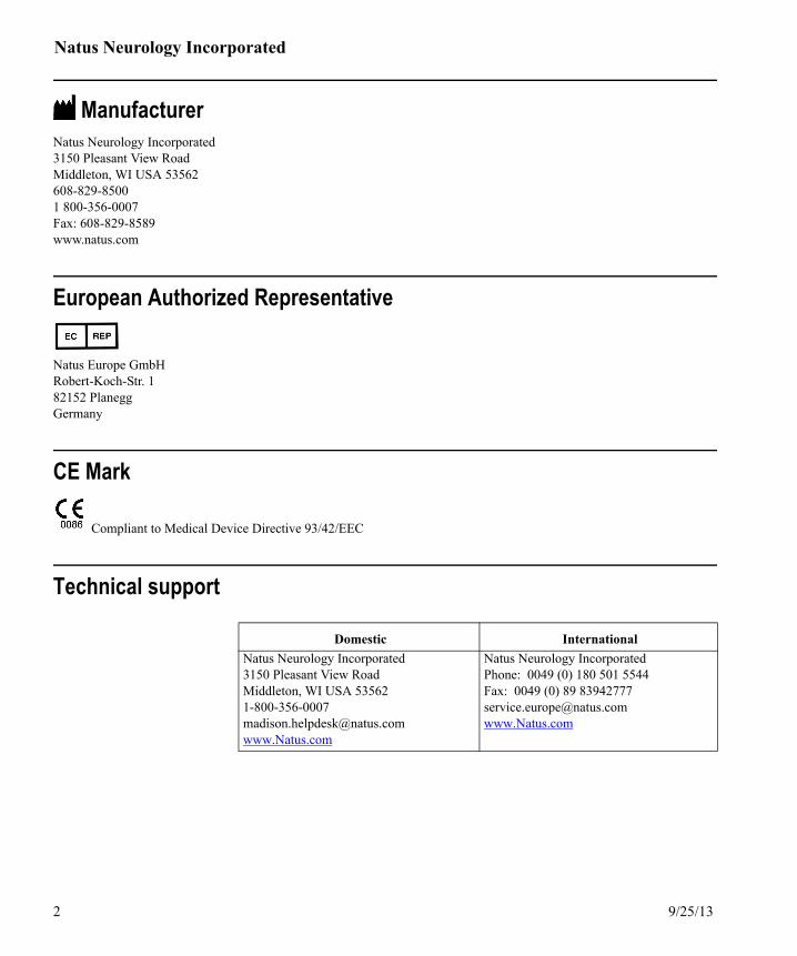
ManufacturerNatus Neurology Incorporated 3150 Pleasant View Road Middleton, WI USA 53562608-829-8500 1 800-356-0007 Fax: 608-829-8589 www.natus.com
European Authorized Representative
Natus Europe GmbHRobert-Koch-Str. 182152 PlaneggGermany
CE Mark
Compliant to Medical Device Directive 93/42/EEC
Technical support
Domestic International
Natus Neurology Incorporated3150 Pleasant View Road Middleton, WI USA 53562 [email protected]
Natus Neurology IncorporatedPhone: 0049 (0) 180 501 5544Fax: 0049 (0) 89 [email protected]
Additional Information and Safety Notes
Safety SummaryIn this guide, two labels identify potentially dangerous or destructive conditions and procedures:
The WARNING label identifies conditions or practices that may present danger to the patient and/or user.
The CAUTION label identifies conditions or practices that could result in damage to the equipment.
U.S. PatentsThe following U.S. Patent Number(s) apply to each applicable Nicolet Brand products.
U.S. Patent Numbers6,366,805, 4,816,8136,463,3226,735,711
9/25/13 3

Natus Neurology Incorporated
Service manuals for your systemA Service manual which contains servicing information that Natus Neurology Incorporated has deemed as appropriate for those parts of your system designated as repairable is available. The Service manual is intended for use only by qualified and trained technical personnel. A charge will be applied for the Service manual.
Natus Neurology Incorporated3150 Pleasant View RoadMiddleton, Wisconsin USA53562-3530
Tel: 608-829-8500Toll free: 1-800-356-0007
World Wide Web: www:natus.com
4 9/25/13

Additional Information and Safety Notes
Specifications Nicolet Brand systemsSpecifications are available from Natus Neurology Incorporated for your system.
Ergonomic environment responsibilitiesThe ergonomic environment surrounding the system or cart may contribute to product risk. It is the responsibility of each institution to ensure users are in a position that meets its human factors/ergonomics/safety requirements.
9/25/13 5

Natus Neurology Incorporated
Preventive maintenance
aa-01 Electrical safety testing is recommended. It is recommended a schedule be established for these purposes, with at least an annual cleaning and safety testing. This system does not require cali-bration unless otherwise stated.
aa-02 Preventative maintenance does not require access to the interior of the instrument and may be performed by the user. For this device, preventative maintenance consists of periodically clean-ing and inspecting the exterior of the instrument.
aa-03 Cleaning consists of removing all dust from the exterior surface of the system with a soft brush or cloth. Use a brush to dislodge any dirt on or around the connectors and panel edges. Remove any dirt with a soft cloth, slightly dampened with a mild detergent solution or cold sterilization agent.
aa-04 Turn OFF system power before cleaning. Prevent detergent solution or cold disinfecting agents from seeping into the electronics of the instrument. Be especially careful around controls, con-nectors and edge panels. Do not use abrasive cleaners.
aa-05 It is recommended that all repairs be performed by a qualified Natus Neurology Incorporated ser-vice representative only. You have the sole responsibility for any malfunctions resulting from improper maintenance or repair by anyone other than an authorized Natus Neurology Incorpo-rated representative.
aa-06 If the system is not functioning properly, do not operate it until all necessary repairs are made and unit is tested for proper functioning in accordance with Natus Neurology Incorporated published specifications. It is recommended that all repairs be performed by a qualified service representa-tive only.
aa-07 See the following Safety Summaries in this publication for additional safety considerations.
aa-08 Switch off all power to the system before attempting any service, maintenance, or preventive maintenance.
aa-09 If the system or any component is repaired, it is recommended that all system functionality be checked and an electrical safety test be performed prior to resuming use.
6 9/25/13

Additional Information and Safety Notes
Cleaning, disinfection and sterilization of parts in contact with the patient
ab-01 The following instructions are subject to change without notice. Always follow the specific pro-cedures that accompanied the parts (e.g., electrodes); your institution's guidelines for cleaning, disinfecting and sterilizing parts; and the instructions from the manufacturer of the sterilizing unit. However, the electrode sterilization temperature must NEVER exceed the value listed on this page, or damage to the electrode may result.
ab-02 Natus Neurology Incorporated electrodesTo help ensure patient safety, prevent cross infections and provide effective service, Natus Neu-rology Incorporated electrodes must be properly maintained. Electrode maintenance should include cleaning and sterilizing before each use.
ab-03 CleaningCleaning is the removal of all foreign material (e.g., soil, organic material) from electrodes. Elec-trodes should be thoroughly cleaned in soap and water using a soft brush. Proper cleaning must precede sterilization.
ab-04 SterilizingElectrodes can be wet or dry autoclaved. Temperatures should not exceed 140° C (284° F). Min-imum recommended cycle time is 10 minutes. See sterilizer manufacturer's instructions for details including duration and loading.
ab-05 Electrodes can be ethylene oxide gas (eto) sterilized. Temperatures should not exceed 133° C (271.4 F) unless otherwise noted in the instructions that shipped with the electrodes. Also see sterilizer manufacturer's instructions for details including: sterilization cycle time, aeration, tem-perature and loading.
ab-06 Natus Neurology Incorporated EEG cup, subdermal, nasopharyngeal, and epidural spinal electrodes cleaning and sterilization instructionsThe following cleaning and sterilization instructions apply to Natus Neurology Incorporated EEG cup electrodes, subdermal electrodes, nasopharyngeal electrodes and epidural spinal elec-trodes.
9/25/13 7

Natus Neurology Incorporated
Cleaning, disinfection and sterilization of parts continued
ab-07 1. Prior to sterilization, electrodes should be thoroughly cleaned using an enzymatic detergent specifically formulated for medical devices. Thorough cleaning must be followed by a thor-ough rinse.
ab-08 2. After cleaning, the electrodes may be soaked in a 2% glutaraldehyde preparation or an EPA registered disinfectant with tuberculocidal properties for disinfection. The electrode should then be thoroughly rinsed.
ab-09 3. Gas or steam sterilization may be used - do not exceed 140° C (284° F).
8 9/25/13

Additional Information and Safety Notes
Safety notes
General safety notesThe Safety Notes apply to all Nicolet Brand systems that have guided you to this publication unless otherwise noted.
Related safety notes have been grouped under various topics. Additional information related to the various safety notes may appear under several topics. Therefore, please read all of the information in this publication.
ac-01 This system is not explosion-proof. Do not use in the presence of flammable anesthetics.
ac-02 Improper grounding is a safety hazard.
ac-03 The system uses a three-wire power cord with a hospital grade plug (for non-U.S.A. applications, the IEC 60601-1 - approved plug). The chassis is earth-grounded. For grounding reliability, connect the device to a hospital grade or hospital only receptacle (for international applications, the IEC 60601-1 - approved receptacle).
ac-04 Inspect the system prior to first startup and frequently prior to usage to examine for and replace damaged components and tighten any loose connections.
ac-05 In all cases, the original data must be reviewed by a trained medical professional if a clinical decision is involved.
ac-06 Use of this device shall only be in medical use rooms.
ac-07 A power interruption during a recording could cause loss of data in the current recording. If you experience frequent power interruptions, Natus Neurology Incorporated recommends you use an Uninterruptable Power Supply (UPS) to help prevent interruptions.
ac-08 Radio transmitting equipment, cellular phones, etc. shall not be used in the close proximity of the device since this could influence the performance of the device.
9/25/13 9

Natus Neurology Incorporated
General safety notes continued
ac-09 Be careful using the equipment near short-wave or micro-wave devices. If the equipment is used in an area where there are therapeutic short-wave or micro-wave devices, remember that these may cause instability and interfere with the correct working of the equipment. Do not place the equipment near X-ray or diathermy devices.
ac-10 The potential for electrical shock is present if device covers are removed. Refer servicing to qualified personnel.
ac-11 For waveform and other specifications, see “Product Specification 169-six digit number” that came with your Natus Brand device.
ac-12 Replace damaged parts immediately. Cables, connectors, accessories, or other parts of the equip-ment must be replaced immediately when damaged or not working correctly. In these cases, con-tact the nearest authorized servicing center.
ac-13 Follow your institution's safety guidelines while installing, servicing, and using the system and any of its components.
ac-14 If the system is dropped or otherwise mishandled, check all system functionality and electrical safety test before resuming use.
ac-15 Use only Natus Neurology Incorporated approved/supplied accessories, software, or components on your system. See your Natus Neurology Incorporated distributor or call 1-800-356-0007 in the USA. Use of non-approved components may adversely affect the functionality of your sys-tem.
10 9/25/13

Additional Information and Safety Notes
General safety notes continued
ac-16 Proper use of this device depends on careful reading of all instructions and labels.
ac-17 Federal law in the U.S.A. and Canada restricts the sale, distribution or use of this device to, by or on the order of a licensed medical practitioner.
ac-18 Use this system only in humidity-controlled, medically used rooms, with an anticipated humidity range of 20-80%.
ac-19 Do not attempt any procedures requiring specialized test equipment or access to the interior of the instrument.
ac-20 Switch off all power to the system before attempting any service and maintenance.
ac-21 The AC power outlets on the iso-power box are intended for use with Nicolet approved compo-nents only. Use of any other equipment may result in damage to the power unit.
ac-22 Do not tilt a laptop's screen back too far or the screen may be damaged.
ac-23 Inspect the power cord often for fraying or other damage. DO NOT operate the apparatus if the power cord or plug is damaged.
ac-24 The brakes fitted to the cart castors should be applied whenever the system is left unattended.
ac-25 Be sure to lock all wheel castors on your system cart before using the system for patient testing. Locked castors help ensure system ground continuity.
ac-26 Ensure the switches to the main system and monitor are OFF and they are unplugged before you begin cabling.
ac-27 Do NOT use cables in the presence of unattended and unsupervised children.
ac-28 Do NOT wrap cables around your neck.
9/25/13 11

Natus Neurology Incorporated
Electrical shock (line voltage)The following Warnings are not all inclusive. Please read all of the Safety Notes in this guide for additional shock warnings.
ad-01 Failure to follow all guidelines may cause electrical shock.
ad-02 Plugging/unplugging power cord in the presence of combustible gas may cause an explosion.
ad-03 System components immersed or in contact with fluids may cause electrical shock.
ad-04 Use of non-Nicolet Brand device(s) could introduce source currents to the patient, which may cause electrical shock.
ad-05 Loss of AC neutral due to damage to the neutral conductor may cause electrical shock.
ad-06 Loss of AC ground connection may cause electrical shock.
ad-07 Over voltage conditions due to a fault in other equipment may cause electrical shock.
ad-08 Over voltage conditions due to application of external voltages to the system may cause electri-cal shock.
ad-09 Over voltage conditions due to the input voltage exceeding the operating range may cause elec-trical shock.
ad-10 Misinstallation of cables on/to the system may cause electrical shock.
ad-11 Use of non-Natus Neurology Incorporated supplied or recommended components or accesso-ries may prevent the application of the risk control measures unique to Natus Neurology Incorpo-rated parts from being applied, which may cause electrical shock.
ad-12 Damaged power cord contacting ungrounded metal component(s) may cause electrical shock.
ad-13 Assembly of computerless systems not per IEC60601-1 may cause electrical shock.
ad-14 Source currents to the patient due to use of Natus Neurology Incorporated repaired (with no leakage testing) components may cause electrical shock.
ad-15 Improper external headbox connections may produce sourcing of current to the patient, which may cause electrical shock.
ad-16 Plugging an electrode into the headbox and allowing the loose ends to make contact with hazard-ous voltages can cause electrical shock.
12 9/25/13

Additional Information and Safety Notes
Data misinterpretation, corruption, loss, false positives, false negatives, etc.The following Cautions describe conditions that may inadvertently alter data and are not all inclusive. Please read all of the Safety Notes in this guide for additional cautions and informa-tion.
ae-01 Adding USB devices while the system is on-line.
ae-02 EMI susceptibility to electro-cautery.
ae-03 EMI susceptibility to diathermy and defibrillation.
ae-04 Swapping the amplifier and stimulator electrodes on the patient.
ae-05 Damaged sensor/electrode device.
ae-06 Misapplication of system hookup.
ae-07 User error resulting in entry of erroneous data.
ae-08 User error resulting in incorrect control of the system.
ae-09 Misdesignation of ‘normal’ signal by unskilled/untrained user under local or remote control.
ae-10 Data transfer error.
ae-11 User error in understanding the data manipulation processes.
ae-12 Loss of system power.
ae-13 Corruption/loss of data over network due to unplugging the network cable or data interruption during data transfer/hardware failure/ corrupt software.
ae-14 Unintended remote control network access to the acquisition system or amplifier.
ae-15 Inadequate network bandwidth.
9/25/13 13

Natus Neurology Incorporated
Data misinterpretation, corruption, loss, false positives, false negatives, etc. continued.
ae-16 Lack of indication of seizure due to incorrect setting of detection parameters or insufficient data collected prior to seizure event.
ae-17 Failure of video capture hardware/software.
ae-18 Corruption of data due to external stimulus applied to the patient (e.g., magnetic stimulation, electrical stimulation or defibrillation, etc.)
ae-19 Data corrupted by frequencies aliased to the data sample rate.
ae-20 User or service error when creating mapper file for patient information imported from the medi-cal center.
ae-21 Inaccurate SpO2 reading after amplifier has been in for service or as a result of improper mainte-nance.
ae-22 Inaccurate SpO2 reading due to using non-Nonin probes or incorrect Nonin probes.
ae-23 Patient manipulation of electrode connections or amplifier settings out of supervision by technol-ogist.
ae-24 System dropped or mechanical damage.
14 9/25/13

Additional Information and Safety Notes
Physical injury
Amplifier arm
Electrodes and transducers
af-01 Warnings in this guide describe conditions that may cause personal injury to the patient and are not all inclusive. Please read all of this guide for additional cautions and information.
ag-01 Take care when removing the amplifier arm tie wrap. The amplifier arm is spring-loaded and may snap open possibly causing injury.
ag-02 When using the amplifier arm, take care not to swing it into the monitor screen. The screen is fragile and may break.
ah-01 Connect patient electrodes to fully electrically-isolated physiological devices only. Connection to any other devices or external electrical outlets may result in personal injury. For patient safety, do not place the metal connectors on the electrode lead wires on a metal surface or any connec-tion to earth ground.
ah-02 Take care when using the equipment simultaneously with other instruments. In the event the patient is connected to several instruments at the same time, it is necessary to remember that the sum of the dispersion currents determined by each instrument may endanger the patient’s life.
ah-03 Simultaneous connection of a patient to high frequency surgical equipment and the Nicolet Brand system may result in burns at the electrode site and damage the Nicolet Brand system.
ah-04 Use only electrodes of adequate size and properly applied by qualified medical personnel to avoid patient skin reactions or burns.
9/25/13 15

Natus Neurology Incorporated
Electrodes and transducers continued.
ah-05 Using electrodes with current densities greater than 2 mA r.m.s./cm2 may require the special attention of the operator.
ah-06 Electrodes of inadequate size or unsuitable application could provoke skin reactions or burns. Natus Neurology Incorporated recommends the use of disposable, pre-gelled, silver/silver chlo-ride electrodes with a contact area of 20 mm diameter or larger. These electrodes contain an adhesive that maintains the electrode skin position and contact during electrical stimulation and are designed for use of the maximum output of the electrical stimulator.
ah-07 Avoid contact of patient and electrodes with conductive metal items. When the equipment is connected to other instruments supplied by the mains, the entire input circuit to which the patient is connected is electrically isolated (floating isolation). It is necessary to avoid the patient and any conductive part connected to the patient (electrodes, connectors, and transducers) from com-ing into contact with conductive parts (ground included). Please observe this precaution to avoid compromising the equipment isolation level. This precaution must be observed in order to avoid accessible metal parts of the device from coming into contact with external conductive parts that could result in damaging the isolation level of the equipment.
ah-08 Although patient connections are electrically isolated, these connections are not intended for direct cardiac contact.
ah-09 Do not allow conductive parts of electrodes and connectors to contact conductive parts or ground.
ah-10 Do NOT touch pins of detached connectors of any kind.
ah-11 The electrode and sensor through which the signal is captured from the body of the patient are not part of the amplifier system. It is MANDATORY to use only electrodes or sensors cleared or approved for commercial use by FDA (USA) or CE marked.
ah-12 Never touch the patient while connecting or disconnecting any connectors.
ah-13 Use only Natus Neurology Incorporated approved/supplied electrodes and transducers. See your Natus Neurology Incorporated distributor or call 1-800-356-0007 in the USA. Use of non-approved electrodes or transducers might adversely affect the function of your system
16 9/25/13

Additional Information and Safety Notes
Electrical stimulators for Nicolet EDX, Nicolet Endeavor, Nicolet VikingSelect, Nicolet VikingQuest, UltraPro S100 and Synergy Plinth and PIU
ai-01 The stimulator probe can deliver electrical output of up to 400 V or 100 mA. This device is intended for use only by or on the order of a licensed medical practitioner.
ai-02 During direct nerve stimulation (i.e., stimulation of an exposed nerve or nerve root), the stimula-tor duration should be limited to 100 s or shorter and the stimulator output level should not exceed 2.5 mA or 10 V.
ai-03 It is necessary to be careful when using the equipment in the case of patients with implanted electric devices, especially heart pace-makers, because the equipment may cause the cardiac stimulator malfunctions. Patients with cardiac pacemakers should not undergo any examination with this equipment without authorization and under the direct control of a specialized physi-cian.
ai-04 Particular precaution must be considered during use of strong emission sources such as High Frequency surgical equipment and similar so that, for example, the HF-cables are not routed on or near the device. If in doubt, contact a qualified technician or your local representative.
ai-05 For initial electrical stimulation, set the electrical intensity (current or voltage) at a low level. Slowly increase the intensity to the desired level of stimulation to prevent patient discomfort.
ai-06 If you disconnect the electrical stimulator from the system with the system power on, an unwanted stimulation of the patient could result.
ai-07 Do not attempt to connect stimulating electrodes directly to the stimulator probe with the probe head removed. You may damage the stimulator probe.
ai-08 Prevent electrode paste from getting into the eye, this could cause eye irritation or possible dam-age.
ai-09 Improper application of electrodes may prevent or interfere with data acquisition.
ai-10 Make sure that the recording electrodes are connected to the amplifier head box and not the elec-trical stimulator. This could result in unwanted stimulation through the recording electrodes.
ai-11 The output waveform of the Electrical stimulator is AC coupled through a transformer. There-fore, there is no DC component. The pulse durations can range from 10uS to 1000uS, the repeti-tion frequencies range from 0.1Hz to 200Hz.
ai-12 The maximum amplitude, in the constant voltage mode, is 400V. The maximum amplitude, in the constant current mode, is 100mA. Both of these maximums are with respect to a 4Kohm load. As the load impedance is increased, the current will drop off according to the equation I = 400V/R. As the load impedance is decreased below 3.2Kohm, the voltage will drop off according to the equation V = 125mA x R.
ai-13 The maximum energy output of the electrical stimulator into a 1Kohm load is (180mA)2 x 1Kohm x 1mS = 32.4mJ.
9/25/13 17

Natus Neurology Incorporated
Stimulation pulse terminology
Auditory stimulator for Nicolet EDX, Nicolet Endeavor, Nicolet VikingSelect, Nicolet VikingQuest, UltraPro S100 and Synergy Plinth
ai-14 The term “pulse duration” or “pulse width” refers to the length of time from point A to point B. The “pulse amplitude” refers to the output level reference from points C and D with a 4000 Ohm load. See Figure 1.
Figure 1
ai-15 Maximum constant current, as listed in the product specifications, will not be achievable with load impedances greater than 4K.
ai-16 Maximum constant voltage, as listed in the product specifications, will not be achievable with load impedances less than 4K.
aj-01 Use of improper auditory transducer or setting high stimulation levels could cause excess stimu-lation and hearing damage.
aj-02 Use of high level or prolonged sound pressure levels may cause permanent hearing loss.
18 9/25/13

Additional Information and Safety Notes
Bovie / Electrocautery
ak-01 Particular precaution must be considered during use of strong emission sources such as High Frequency surgical equipment and similar so that, for example, the HF-cables are not routed on or near the device. If in doubt, contact a qualified technician or your local representative.
ak-02 Always use appropriate Bovie (high frequency surgical equipment) protection devices with amplifiers for connecting all recording electrodes. Use the largest surface area electrode possible for the patient ground electrode. Avoid prolonged activation of the Electrosurgery Unit (ESU). Avoid ESU activation in close proximity of the monitoring electrodes. Read and follow all safety guidelines for operating room systems.
ak-03 Always use an O.R. headbox for connecting electrodes when electrocautery devices are used.
ak-04 Always use appropriate electrocautery protection devices for connecting all recording electrodes to amplifier(s).
ak-05 Do not apply metal or electrodes to a patient being treated with Diathermy therapy. Burns and/or shock may occur at the site of any metal-to-patient contact.
ak-06 When the system is used simultaneously with high frequency surgical equipment, burns may occur at the recording or stimulating electrode site.
ak-07 Take care when using the equipment at the same time with other radio frequency instruments. In the event the equipment is used in a surgery room at the same time with a radio knife (Radio-Frequency instrument = RF), it is necessary to hold the radio knife point as far as possible from the electrodes, in order to reduce the risk of RF currents effect on the electrodes and consequent burns to the patient. Therefore, it is necessary to use electrodes with a larger surface contact with the patient’s body, in order to limit the RF current density to acceptable values. If it is not possi-ble to use the proper electrodes, disconnect the patient from the equipment before using radio-frequency instruments.
ak-08 While running high frequency surgical units, the recording of data may not be possible while the surgical unit is active.
ak-09 Do not place the equipment near X-ray or diathermy devices.
9/25/13 19

Natus Neurology Incorporated
Implant electrodes
EMG
Leakage current
al-01 Advise patients with implanted electronic devices not to be subjected to electrical stimulation unless specialist medical opinions have first been obtained.
am-01 For initial electrical stimulation, set the electrical intensity (current or voltage) at a low level. Slowly increase the intensity to the desired level of stimulation to guard against patient discom-fort.
am-02 For safety and efficiency during electrical stimulation, the cathode and anode spacing should not exceed 4.0 cm.
am-03 During direct nerve stimulation (stimulation of an exposed nerve or nerve root), the stimulator duration should be limited to 100 µsec. or shorter and stimulator output level should not exceed 2.5 mA or 10 V.
am-04 Prior to each case, check stimulation functionality. If ever in doubt, always reverify the func-tionality of the stimulators.
an-01 This instrument is designed to comply with the European standard for medical electronic equip-ment IEC/EN 60601-1, which lays down the permissible levels of leakage current from individ-ual products. A potential hazard exists in the summation of leakage currents caused by connecting multiple pieces of equipment together. Because this instrument can be used in con-junction with standard electronic devices, the total leakage current should be tested at regular intervals.
20 9/25/13

Additional Information and Safety Notes
Batteries
Recycling / disposal
ao-01 Exposing Lithium-Manganese Dioxide (LiMnO2) batteries to extended, hot temperatures may cause the batteries to fail or explode. Do not allow the batteries to exceed 140 degrees F (60 degrees C).
ao-02 Where applicable, instructions for those systems using batteries as the primary power source are located in the main User's guide. Additional information from the manufacturer concerning the battery (battery charger) may also have accompanied your system.
ao-03 Do not dispose of batteries by incineration.
ap-01 Many local laws and regulations consider electric equipment-related waste as hazardous or requiring special procedures to recycle or dispose of. This includes batteries, printed circuit boards, electronic components, wiring and other elements of electronic devices. Follow all of your respective local laws and regulations for the proper disposal of batteries and any other parts of your system, such as monitors, amplifiers, keyboards, electrodes, etc.D
ap-02 Check theNatus website for recommended instructions and addresses for proper return or dis-posal of electronic wastes relating to Nicolet Brand products in Europe and other localities.
ap-03 The contact information for the Waste Electrical and Electronic Equipment (WEEE) - In EuropeEuropean authority representativeNatus Europe GmbHRobert-Koch-Str. 182152 PlaneggGermany
9/25/13 21

Natus Neurology Incorporated
Defibrillation
Mains operated equipment with additional power supply
Replacement of fuses and other parts
Hard drive
aq-01 This system is not protected against defibrillation. Remove the patient connections to the sys-tem prior to defibrillation. If defibrillation is applied to the patient while still connected to this system, you may damage the system.
aq-02 Always test system operation and leakage current after defibrillating your patient.
ar-01 If there is any doubt about the external Protective Earth Conductor arrangement's integrity for Class I Equipment connected to a Supply Mains and alternatively used with an Internal Electri-cal Power Source, the equipment should be operated from its Internal Electrical Power Source. Serious injury or damage to the system may result otherwise.
ar-02 For mains operated systems using an additional power source which is not automatically main-tained in a fully usable condition, periodic testing or replacement of the additional power source is recommended.
as-01 Instructions for changing fuses for the Isolation Transformer (if applicable for your system) is located in the installation instructions, which shipped with your system. This document will typ-ically be labelled as Users Guide or, in some instances, Read Me First or Utilities Guide.
as-02 Likewise, instructions for connecting interchangeable and/or detachable parts to your system is located in the installation instructions, which shipped with your system.
at-01 Do not attempt to reformat the hard drive without consulting a qualified Natus Neurology Incor-porated Service Representative first. Initializing and reformatting the hard disk erases all data previously stored on the system. Follow the steps listed in the Natus Neurology Incorporated documentation or only under the direction of a qualified Service Representative.
22 9/25/13
Additional Information and Safety Notes
Restricted environmental conditions for operation, transport and storage
au-01 The following general information (subject to change without notice) is applica-ble to your system unless otherwise noted.
au-02 Operating (in use)The following information is applicable to all systems in this publication unless otherwise noted in the specific system’s User guide.• Temperature: 60 to 90° F, (15.6 to 32.2° C).• Relative Humidity: 20-80%, noncondensing.• Altitude: 0-10,000 ft, (0-3 km).
au-03 Nonoperating (in storage)The following information is applicable to all systems in this publication unless otherwise noted in the specific system’s User guide.• Temperature: 0 to 132° F, (-17.7 to 55° C).• Relative Humidity: 10% - 90%, noncondensing.• Altitude: 0-40,000 ft, (0-12 km).
au-04 Shipping conditionsNormal instrument shipping conditions may exceed recommended storage and operating speci-fications. Original instrument packaging has been designed to allow shipment and storage in typical shipping conditions for up to 60 days.
au-05 Typical shipping conditions may range in temperature from -34° C to 65° C, and humidity lev-els may vary from 15% - 95%, noncondensing.
au-06 Protective packaging measuresThis equipment is designed for normal medical use. For storage and transportation, additional protection from environmental conditions and handling is recommended. Protect from conden-sation and impact.
9/25/13 23

Natus Neurology Incorporated
Electrodes and Amplifiers
av-01 Do not measure the impedance of indwelling grid electrodes or needle electrodes with the nee-dle positioned in the patient. This practice may result in patient injury.
av-02 Do not measure the impedance of electrodes in contact with your patient’s cornea. This practice may result in patient injury.
av-03 Using electrodes with current densities greater than 2 mA r.m.s./cm2 may require the special attention of the operator.
av-04 Electrode application materials can cause eye irritation. Avoid contact with the eyes.
av-05 To reduce the risk of injury, disconnect all recording and stimulating electrodes from the system before you turn the system power off and on.
av-06 Connect all patient electrodes to fully electrically-isolated physiological devices only. Connec-tion to any other devices or external electrical outlets may result in personal injury.
av-07 Do not stimulate a patient with an implanted electronic device, such as a cardiac pacemaker, without the approval of a licensed medical practitioner.
av-08 Do not operate the stimulator in close proximity (i.e., less than 1 meter) to a shortwave or microwave therapy device. This practice may lead to unstable electrical stimulus output, which may cause patient burns.
av-09 Electrodes of inadequate size or unsuitable application could provoke skin reactions or burns. Natus Neurology Incorporated recommends the use of disposable, pre-gelled, silver/silver chlo-ride electrodes with a contact area of 20 mm diameter or larger. These electrodes contain an adhesive that maintains the electrode skin position and contact during electrical stimulation and are designed for use of the maximum output of the electrical stimulator.
av-10 Always use the largest surface electrodes possible for the patient ground electrode.
av-11 Do not set the amplifier on the operating room floor or any other floor on which the amplifier may come in contact with any kind of fluids.
av-12 The v32 Amplifier is not for use in the Operating Room.
24 9/25/13

Additional Information and Safety Notes
Isolation / Isolation transformer
aw-01 This system is for use only with the Nicolet Brand Isolation Boxes designed for use with your system.
aw-02 Power the system from the Isolation Transformer (if one is configured with your system) to guard against the loss of isolation protection.
aw-03 Use the isolated outlets on the Iso-Box to connect Natus Neurology Incorporated recommended devices only. Using any other device could open the circuit breaker resulting in a system shut-down.
aw-04 Although patient connections are electrically isolated, these connections are not intended for direct cardiac contact.
aw-05 It is the responsibility of the user to ensure that conformance to IEC/EN 60601-1 Type BF patient isolation requirements is maintained when patient-connected equipment or accessories not supplied by Natus Neurology Incorporated or its authorized agent are used with Nicolet Brand equipment.
aw-06 Before you dissemble the AC input on the Isolation Transformer (ISO) box, make sure system power is OFF and the power cord is disconnected from the external (wall) outlet to prevent pos-sible injury from electrical shock.
aw-07 For proper isolation while the patient is connected to the system, connect only a battery-pow-ered or independently-isolated printer to the system.
aw-08 Connect patient electrodes to fully electrically-isolated physiological devices only. Connection to any other devices or external electrical outlets may result in personal injury.
aw-09 When more than one medical device is connected to the patient, leakage currents of the devices are summed together. Use caution.
aw-10 Periodically check the system ground integrity, the system leakage current and the leakage cur-rent of the amplifier.
aw-11 The power outlets on the ISO box are intended for use only with Natus Neurology Incorpo-rated-approved system components. Use of any other equipment could result in damage to the power system or compromise patient isolation.
aw-12
Where applicable, a potential equalization connection point is provided on the Iso-Box or chassis of the device for connection to the corresponding parts of other devices connected to the patient. Such connections may be used to help reduce the incidence of ground and/or leakage currents which can occur through patient connections of devices with separate grounding sys-tems.
9/25/13 25

Natus Neurology Incorporated
Software
ax-01 Natus Neurology Incorporated has taken reasonable measures to ensure that the software will remain unaffected by the presence of other, third-party software programs. However, given the vast number of software programs available, Natus Neurology Incorporated cannot ensure com-plete immunity, nor can Natus Neurology Incorporated guarantee immunity against software viruses.
ax-02 Any user who installs third-party software on the Nicolet Brand system or alters the Natus Neu-rology Incorporated software code assumes all risks and liabilities in doing so. The user will be subject to service charges to restore the system to normal operation, even if the system is within the warranty period or under service contract.
ax-03 Do not attempt to reinstall the software without consulting a qualified Natus Neurology Incor-porated Service Representative first. You can destroy all of your data. Follow the steps provided only under the direction of a qualified Service Representative.
ax-04 Do not run virus scanning software or any other terminate-and-stay-resident programs while running Natus Neurology Incorporated software. Programs running in the background may adversely affect the performance of Natus Neurology Incorporated software.
ax-05 Do not have a firewall running while using Natus Neurology Incorporated software.
ax-06 The customer is responsible for maintaining all system software in a safe, secure location.
ax-07 To reduce the risk of system problems, do not minimize or resize the Natus Neurology Incorpo-rated program’s window when working outside the program. Always close the program using the Exit option or the Shutdown option under Help, ETC (on the Home Page), when working in a different application.
ax-08 Evoked Potential ( EP ) functions, Base Line Correct, Invert and Smooth, cause permanent changes in the averaged data. If you need the original traces, save them to the hard disk before performing these functions.
ax-09 Follow the shutdown sequence described in the system’s User or Reference manual to turn off the system to insure the integrity of your data files.
ax-10 Natus Neurology Incorporated programs are not intended for data acquisition on any nonmedi-cal device (such as a standard PC) that comes in direct electrical contact with a patient.
ax-11 Do NOT change the system clock during a session. If you need to change the clock, exit the Nicolet Brand system’s program first.
26 9/25/13
Additional Information and Safety Notes
Electromagnetic Compatibility (EMC) Information
ay-01 The use of accessories, transducers and cables other than those specified, with the exception of servicing parts sold by Natus Neurology Incorporated as replacement parts for internal compo-nents, may result in increased EMISSIONS or decreased IMMUNITY of the device.
ay-02 Your Nicolet Brand system has been tested for EMC emissions and immunity as a stand-alone instrument. Do not use the system adjacent to or stacked with other electronic equipment. If adjacent or stacked use is necessary, the user should verify normal operation in that configura-tion.
ay-03 EMI by nature can be a possible source of disturbance to electronic equipment. This device should be used in an environment free* of other equipment that could be affected by interfer-ence *Environment free described in IEC 1000-2-3, Part 2, First Edition.
ay-04 Be careful using the equipment in locations disturbed by strong magnetic fields. The equipment is compliant with the EMC requirements (Electromagnetic Compatibility) according to what is specified by the EN 60601-1-2 standard. It is recommended that the equipment be kept away from disturbance sources and induced electromagnetic fields surpassing the values prescribed by the standard in order to avoid any possible instabilities and malfunctioning of the equipment.
ay-05 Medical Electrical Equipment needs special precautions regarding EMC and needs to be installed and put into service according to the EMC information provided in this manual and the CD (part number 482-638702) that shipped with your system.
ay-06 Portable and mobile RF communications equipment can affect the system. Install and operate the system according to the EMC information presented on the CD (part number 482-638702) that shipped with your system.
9/25/13 27
Natus Neurology Incorporated
ESD handling
az-01 Pins of USB connectors identified with the ESD warning symbol should not be touched and connections should not be made to these connectors unless ESD precautionary procedures are used.
az-02 Accessible pins of USB connectors identified with the ESD warning symbol should not be touched with the fingers or with a hand-held tool unless proper precautionary procedures have been followed.Precautionary procedures include:• Methods to prevent build-up of electrostatic charge (e.g., air conditioning, humidification,
conductive floor coverings, non-synthetic clothing);• Discharging one’s body to the frame of the EQUIPMENT or SYSTEM or to earth or a large
metal object;• Bonding oneself by means of a wrist trap to the EQUIPMENT or SYSTEM or to earth. Staff
that could touch USB connectors identified with the ESD warning symbol should receive this explanation and training. This includes clinical/biomedical engineering and health-care staff.
az-03 ESD training should include an introduction to the physics of electrostatic charge, the voltage levels that can occur in normal practice and the damage that can be done to electronic compo-nents if they are touched by an OPERATOR who is electrostatically charged. Further, an expla-nation should be given of methods to prevent build-up of electrostatic charge, and how and why to discharge one’s body to earth or to the frame of the EQUIPMENT or SYSTEM, or bond one-self by means of a wrist strap to the EQUIPMENT or SYSTEM or to earth prior to making a connection.
az-04 Touching the monitor screen with your fingers can create a static charge that may affect the data display.
28 9/25/13

Additional Information and Safety Notes
Networking
ba-01 When connected to a network the system must meet requirements of IEC 60601-1-1.
ba-02 Any person who connects external equipment to signal input, signal output or other connectors of Nicolet Brand Medical Equipment has formed a system and is therefore responsible for the system to comply with the requirements of IEC 60601-1-1 “Safety requirements for medical electrical systems”. If in doubt, contact qualified technician or your local representative.
ba-03 External equipment intended for connection to signal input, signal output or other connectors of Nicolet Brand Medical equipment, shall comply with relevant IEC standards. (e.g. IEC 60950 for IT equipment and the IEC 60601-1 for medical electrical equipment). In addition, all such combinations – systems - shall comply with the standard IEC 60601-1-1 “Safety requirements for medical electrical systems”. Equipment not complying to IEC 60601 shall be kept outside the patient environment, as defined in the standard. (Patient environment is generally consid-ered the environment within 1.5 meters of the patient.)
ba-04 Equipment not complying with IEC 60601-1 shall be kept outside the patient environment, as defined in the standard, (at least 1.5m from the patient).
ba-05 Do not connect the system to a telephone line while connected to the patient.
ba-06 Do not connect the unit to a telephone line or through a modem to a telephone line when the unit is connected to a patient.
ba-07 To minimize the risk of patient or user injury when networking a Nicolet Brand medical device to any other equipment, please do the following:1. The user must have a network server that is IEC 950, EN 60950 or UL 1950 certified to
maintain proper electrical isolation between the AC line and the patient.
2. Before connecting a patient to any Nicolet Brand device that is attached to a network, the user must measure patient leakage of the Nicolet Brand medical device, with all intended equipment attached to the network, and ensure that patient leakage is within acceptable lim-its.
9/25/13 29

Natus Neurology Incorporated
Operating environment
bb-01 The equipment is not designed to be used in locations with inflammable vapors or gases that may cause explosions. The equipment must not be used in atmospheres with a high concentra-tion of oxygen or in buildings where inflammable substances or anesthetic agents are present. The atmosphere is considered as oxygen-saturated when the oxygen or nitrous oxide (N2O) concentration contained in the environment is over 24%.
bb-02 The equipment and its internal parts are not protected against the inflow of liquids. Avoid sub-mitting the equipment to the risk of water or other fluids dripping, sprinkling or immersion and using the equipment where such risks are present. Devices in which liquids have accidentally penetrated must be immediately cleaned and checked by authorized qualified staff.
bb-03 Use caution when moving the equipment between locations with different temperatures to avoid any possible condensation. If the equipment is stored in a cold place and is rapidly moved to a warmer building, condensation may occur (humidity or misting over the internal or external sur-face of the equipment). In this case it is necessary to wait for the humidity to completely evapo-rate before using the equipment.
bb-04 Make sure the electric wiring of the building is sufficient for connection to other mains powered devices. When the equipment is connected to peripherals or other mains powered devices, make sure that they are connected only to mains outlets with protective grounding. This protection is fundamental for the patient’s and the user’s safety: therefore, it is necessary that the electric wir-ing of the building guarantees an efficient protective grounding.
bb-05 Be careful using the equipment in locations disturbed by strong magnetic fields. The equipment is compliant with the EMC requirements (Electromagnetic Compatibility) according to what is specified by the EN 60601-1-2 standard. It is recommended that the equipment be kept away from disturbance sources and induced electromagnetic fields surpassing the values prescribed by the standard in order to avoid any possible instabilities and malfunctioning of the equipment.
bb-06 Do not allow any liquid to enter the case of any instrument or connector.
bb-07 Do not use acetone on any of the instruments.
30 9/25/13

Additional Information and Safety Notes
System connections
bc-01 Do not connect a telephone line to either the LAN connector or Visual Stimulator connector. To do so may compromise patient isolation.
bc-02 All patient connections to the equipment are through the device using the input sockets pro-vided, or through the dedicated connector for pre-wired headset. Any patient electrodes con-nected to the device by any other means constitute an unsafe condition that could result in injury or death to the patient.
bc-03 All connections on the headbox are isolated from AC power ground. Do NOT join these con-nections to earth ground or AC power ground since such an action constitute an unsafe condi-tion that could result in serious injury or accidental death to the patient.
bc-04 Do not connect items (accessories and peripherals) which are not specified as part of the system. In order to guarantee all the safety requirements, it is necessary to use only the accessories and peripherals specified by Natus Neurology Incorporated as part of the system, which have been tested with the equipment. The use of accessories and consumer goods supplied by other manu-facturers or not specifically indicated by Natus Neurology Incorporated does not guarantee the safety and the correct working of the equipment. Use only peripherals in compliance with the standards of the class to which they belong.
bc-05 Observe the EN/IEC 60601-1-1 and EN/IEC 60601-1-2 standards in case of connection with other instruments. The connection of the equipment with other devices is allowed only when the safety requirements for the patient, the user and the environment are not compromised. If the Natus Neurology Incorporated documentation does not contain adequate information about the possibility of interconnection with other devices, the user should contact the manufacturer or the nearest authorized servicing center to obtain information about the effects that coupling devices may have on the patient, the user and the environment.
bc-06 Do not use additional Multiple Portable Socket-Outlet or extension cords.
bc-07 If you disconnect any cables, take care to reconnect them correctly to guard against damage to the system or components.
9/25/13 31

Natus Neurology Incorporated
System connections continued.
bc-08 Federal law in the U.S.A. and Canada restricts the sale, distribution or use of this device to, by or on the order of a licensed medical practitioner.
bc-09 Turn OFF system power before connecting or disconnecting any system component(s) or acces-sories. You may damage the device(s).
bc-10 All nonmedical equipment connected to this device, such as printers, must comply with IEC 950 and/or appropriate European Directives.
bc-11 Connect all nonmedical equipment to a Natus Neurology Incorporated Isolated Power Supply.
bc-12 Take care not to overtighten any screws used to assemble and secure system components. Over-tightening may damage the components.
bc-13 Do not turn on any system power until all cables have been properly connected and verified.
32 9/25/13
Additional Information and Safety Notes
Product Specific Cautions and Warnings
Nicolet cEEG, Nicolet nEEG / LTM, Nicolet Monitor, and Nicolet vEEG
da-01 Connect only the proper specified power supply to the Nic36 Amplifier. In order to guarantee the electrical safety requirements, the equipment must be powered by means of the proper med-ical AC/DC adapter only.
da-02 For use of the Nicolet system for Interoperative Monitoring, consult your Natus Neurology Incorporated representative for a copy of the Interoperative Monitoring Guidelines.
da-03 Do not connect additional Multiple Portable Socket-Outlet (MPSO) or extension cords to the system.
da-04 The Multiple Portable Socket Outlet (MPSO) provided with the system shall only be used for powering equipment which forms part of the system.
da-05 The Multiple Portable Socket Outlet (MPSO) and the NicPSU shall not be placed on the floor.
da-06 For Nicolet cEEG and Nicolet nEEG and LTM systems using an Intuition amplifier, perform an Impedance Check BEFORE selecting the Calibrate Mode to assure the galvanic integrity of the A1 and A2 reference electrodes.
da-07 The Power Strip may be used ONLY if the cart is NOT in the patient's vicinity.
da-08 The event detection and alert features for this system are NOT to be used as Alarm functions and are NOT to be used in place of vital signs monitoring and alarm equipment.
da-09 Product has No alarms. Proper professional monitoring of patient and display outputs is required during the use of the system. Do not use the system as an alarm for the patient’s well being. Built in indicators and markers are not intended for Alarm purposes.
da-10 All patient connections to the equipment are through the device using the input sockets pro-vided, or through the dedicated connector for pre-wired headset. Any patient electrodes con-nected to the device by any other means constitute an unsafe condition that could result in injury or death to the patient.
9/25/13 33

Natus Neurology Incorporated
Nicolet cEEG, Nicolet nEEG / LTM, Nicolet Monitor, and Nicolet vEEG continued
da-11 All connections on the headbox are isolated from AC power ground. Do NOT join these connec-tions to earth ground or AC power ground since such an action constitutes an unsafe condition that could result in serious injury or accidental death to the patient.
da-12 The power supply is supplied with the equipment. The allowed model is: P/N 113-104700.
da-13 Take care when using the equipment at the same time with other radio frequency instruments. In the event the equipment is used in a surgery room at the same time with a radio knife (Radio-Frequency instrument = RF), it is necessary to hold the radio knife point as far as possible from the electrodes, in order to reduce the risk of RF currents effect on the electrodes and consequent burns to the patient. Therefore, it is necessary to use electrodes with a larger surface contact with the patient’s body, in order to limit the RF current density to acceptable values. If it is not possi-ble to use the proper electrodes, disconnect the patient from the equipment before using radio-frequency instruments.
da-14 When configuring Nicolet components with other components, you are creating a medical sys-tem and you must be aware and abide by requirements of IEC 60601-1-x. This includes but is not limited to carts, power supplies, mains outlet connections, computers, or other devices. Sys-tems without a Natus Neurology Incorporated Iso Box or systems using non-Natus Neurology Incorporated approved components are at risk of increased leakage current and reduced dielec-tric strength, which could cause shock to the user or patient during user contact.
da-15 It is the responsibility of the user to ensure that conformance to IEC/EN 60601-1 Type BF patient isolation requirements is maintained when patient-connected equipment or accessories not supplied by Natus Neurology Incorporated or its authorized agent are used with Natus Neu-rology Incorporated equipment.
da-16 Full compliance of Nicolet systems cannot be ensured unless all components (leads, etc.) are provided by Natus Neurology Incorporated or its authorized agent. Do not connect items not specified as part of the Nicolet system to the system.
da-17 Any non-medical equipment connected to medical equipment to form a medical electrical sys-tem must comply with an appropriate safety standard, for example IEC 60950, EN 60950, UL 1950, CAN/CSA 22.2 No 950.
da-18 Items not specified as a part of a Nicolet system must not be connected to the system.
da-19 There is no industry standard for grid and strip electrode numbering. It is your responsibility to verify that the grid and strip layout and numbering match for all selected implants.
34 9/25/13

Additional Information and Safety Notes
Nicolet cEEG, Nicolet nEEG / LTM, Nicolet Monitor, and Nicolet vEEG continued
da-20 The Photic Stimulator used with AllianceWorks and Intuition amplifiers (P/N 842-658100) is intended for short-time operation only. To guard against damage to the photic strobe and photic power supply from overheating, follow these guidelines:Up to 30 Hz: 25% duty cycle with maximum, continuous on time of 15 minutes.31-60Hz: 25% duty cycle with maximum continuous on time of 5 minutes.
da-21 For configurations with a power strip (no Iso Box), the power strip, desktop PC, digital video components, printer and NicDCIN Box must be located outside of the patient environment (1.5 meters away from the patient). For configurations with a power strip (no Iso Box), the power strip, desktop PC, digital video components, printer and NicDCIN Box must be located outside of the patient environment (1.5 meters away from the patient).
da-22 The v32 and v44 Amplifiers are not approved for use with the Luxor arm on the Photic Stand due to tipping hazards.
da-23 The v32 Amplifier is not for use in the Operating Room.
da-24 After repairing any parts powered with line voltage, the system must be tested and pass a leak-age current test before the system is used again.
da-25 When using Grid/Strip/Depth electrodes, perform an image scan to confirm that the electrodes have been anatomically positioned properly on the patient.
da-26 All alerts triggered via a predefined event (for example, seizure) must be verified by both inspecting the displayed waveform data and visually observing the patient.
da-27 Patient Auxiliary Current SFC DC Type BF limit exceeded if calibration mode is entered and A1 or A2 electrode leads are not connected may cause electrical shock.
da-28 Plugging the headcap DB25 connector into an inappropriate connection may cause an electrical shock.
9/25/13 35
Natus Neurology Incorporated
Nicolet Endeavor and Nicolet Endeavor CR
db-01 The Nicolet Endeavor CR has been tested to and complies with Industry standards for suscepti-bilities to electromagnetic phenomena for Medical Electrical Devices in accordance with IEC 60601-1-2; this device meets all requirements of this international standard.
db-02 This system is intended for continuous operation and has an electrical protective classification of Class I, Type BF and Type B applied parts, ordinary equipment, not suitable for use in the presence of flammable anesthetics.
db-03 The headbox shows important warning symbols put there to remind you that the connections are intended for isolated patient connections only. This device is not designed or intended to be used with 2mm pin connectors. It is designed and intended for use only with Natus Neurology Incorporated approved protected pin style connectors.
db-04 Do NOT use Stack Panel acquisition displays for diagnostic decisions, Stack Panel acquisition screen displays only update at completion.
db-05 Make sure the electric wiring of the building is sufficient for connection to other mains pow-ered devices. When the equipment is connected to peripherals or other mains powered devices, make sure that they are connected only to mains outlets with protective grounding. This protec-tion is fundamental for the patient’s and the user’s safety: therefore, it is necessary that the elec-tric wiring of the building guarantees an efficient protective grounding.
db-06 The system amplifier is not intended to be touched by the patient. Do not touch the system amplifier and patient at the same time. The system amplifier is to be installed and maintained outside the patient environment (the patient environment is the space within 1.5 meters from the patient).
db-07 The UniCart/Flat Panel Cart/Desktop systems are not installable by the user. They must be installed by a qualified and trained Natus Neurology Incorporatede Service Representative. The Nicolet Endeavor and Nicolet Endeavor CR Portable system is installable by the user.
db-08 If you click on the Start Average (or the Start or Restart Repeating Average) button while signals are being averaged, the counter resets to 0/0 and the average starts over again. Make sure you really want to reset the average before clicking on the button while averaging is in pro-cess.
db-09 Only use templates that were created with stimulators to acquire patient data. Templates cre-ated with a simulator are for demonstrations/didactic purposes only.
36 9/25/13

Additional Information and Safety Notes
Nicolet EDX, Nicolet VikingQuest, Nicolet VikingSelect, UltraPro S100, Synergy Plinth and PIU
dc-01 Do not disconnect or reconnect the system amplifier modules with system power on. You may damage the amplifiers.
dc-02 Do not load any printer drivers supplied with your printer onto the Nicolet system. Doing so may cause printer problems. Use only the drivers supplied by Natus Neurology Incorporated. These drivers have been tested thoroughly for use with the system.
dc-03 Because the Nicolet EDX and the Nicolet VikingQuest system base unit is electrically isolated, the base unit can be connected to the Isolation transformer outlet labelled “Non-isolated” output on cart base systems. Do not connect any other device to this outlet or current leakage limits may be exceeded.
dc-04 Use the Shutdown command located on Utilities menu to exit the system program before you turn off system power. If you do not use this command before exiting the program or turning off the system, patient data and settings files may be damaged causing loss of data.
dc-05 You must save test data by pressing the Store Data key on the Record mode DPA line before entering the Settings Files to make parameter changes. If you change the trace mode without storing current data first, you may lose your data.
dc-06 Do not connect additional Multiple Portable Socket-Outlet (MPSO) or extension cords to the system.
dc-07 The Multiple Portable Socket Outlet (MPSO) provided with the system shall only be used for powering equipment which forms part of the system.
9/25/13 37

Natus Neurology Incorporated
Nicolet EDX, Nicolet VikingQuest, Nicolet VikingSelect, Synergy continued
dc-08 The Multiple Portable Socket Outlet (MPSO) shall not be placed on the floor.
dc-09 This system is intended for continuous use and has a protective classification of Class I ordinary equipment, not suitable for use in the presence of flammable anesthetics, with Types B and BF applied parts.
dc-10 If you are working in a Windows program and are ready to turn off the system, you must close the Windows application and Windows before powering down. You must quit Windows by selecting Shut Down on the Windows Start Menu. If you do not close the program properly, you may damage the data files or the Windows file structure.
dc-11 To reduce the risk of system problems, do not minimize or resize the Nicolet Viking window when working outside the Nicolet Viking Program. Always close the Nicolet Viking Program using the Exit Nicolet Viking option or the Shutdown option on the Nicolet Viking menu when working in a different application.
dc-12 The EP functions, Base Line Correct, Invert and Smooth, cause permanent changes in the aver-aged data. If you need the original traces, save them to the hard disk before performing these functions.
dc-13 If you have the plastic supplies container on your system, do not use the following chemicals, solvents or derivatives to clean the container: acetone, benzene or toluene. You may damage the container’s surface.
dc-14Prolonged electrical stimulation can cause a patient burn.
38 9/25/13

Additional Information and Safety Notes
Nicolet Ambulatory EEG
Nicolet 2015 Visual Stimulator
dd-01 Natus Neurology Incorporated does not supply EEG electrodes. The PCU accepts standard 1.5 mm touchproof electrodes using DIN 42802-style connectors. To ensure patient safety, the elec-trodes used must be approved to the appropriate Medical Device Directive or relevant local stan-dards.
dd-02 The Recorder must only be connected to the medical-grade power supply provided with the unit. It must not be used with any other power supply. If the medical-grade power supply is not used, the system may not perform as intended, and the safety of personnel may be at risk.
dd-03 Always use the power lead and connector supplied with the Recorder, or a lead and connector of equivalent standard.
dd-04 Never use adaptor plugs or extension leads.
dd-05 Only appropriately trained and qualified personnel should adjust, maintain or repair an instru-ment.
dd-06 Always disconnect the instrument from the main power supply before removing any covers.
dd-07 The conductive part of electrodes and their connectors, including the Neutral electrode, should not contact other conductive parts including earth.
dd-08 When in close proximity to the Recorder, do not use mobile phones, transmitters, power trans-formers, motors, or other equipment that generates magnetic fields.
dd-09 Do not obstruct any cooling slots. Position the instrument so that air flows freely.
dd-10 Do not attempt to do a low-level format, or do a standard format using a SCSI or USB card reader.
de-01 This device is not user installable.
de-02 Only connect this accessory to Natus Neurology Incorporated-supplied or recommended devices.
de-03 Disconnect all detached power cables from the AC power supply. Remove all unused power cables from the location of the monitoring device.
de-04 Electrical shock hazards exist. Do not remove covers. Refer servicing to qualified service pro-fessionals.
de-05 Periodically check the system ground integrity and the system leakage current.
9/25/13 39
Natus Neurology Incorporated
NONIN Pulse Oximeters
df-01 Do not use NONIN Pulse Oximeters in an MRI environment.
df-02 NONIN Pulse Oximeters have no alarms, do not use when alarms are required.
df-03 Explosion hazard, do not use in an explosive environment.
df-04 The NONIN Pulse Oximeter is intended only as an adjunct in patient assessment. It must be used in conjunction with other methods of assessing clinical signs and symptoms.
df-05 Use only NONIN-manufactured pulse oximeter sensors. These sensors are manufactured to meet the accuracy specifications for NONIN Pulse Oximeters.
df-06 As with all medical equipment, carefully route patient cabling to reduce the possibility of patient entanglement or strangulation.
df-07 Check the pulse oximeter sensor application site frequently to determine the positioning of the sensor and the circulation and skin sensitivity of the patient. Each patient’s sensitivity to NONIN sensors may vary depending on their medical status or skin condition.
df-08 Discontinue use of adhesive tape strips if the patient exhibits an allergic reaction to the adhesive material.
df-09 Do not stretch the adhesive tape while applying the pulse oximeter sensor. This may cause inac-curate readings or skin blisters.
df-10 General operation of NONIN Pulse Oximeters may be affected by the use of Electrocautery.
df-11 Do not use a damaged sensor.
df-12 NONIN Pulse Oximeters should not be used adjacent to or stacked with other equipment. If adjacent or stacked use is necessary, the device should be observed carefully to verify normal operation.
df-13 he use of accessories, sensor, and cables other than those listed in the NONIN Pulse Oximeters documentation/manual may result in increased emission and/or decreased immunity of this device.
df-14 Federal law in the U.S.A. and Canada restricts the sale, distribution or use of this device to, by or on the order of a licensed medical practitioner.
df-15 Read the Nicolet Software Reference guide 269-604601 manual carefully before using NONIN Pulse Oximeters.
40 9/25/13

Additional Information and Safety Notes
NONIN Pulse Oximeters continued.
df-16 Before use, carefully read the package insert provided with the oximetry sensors.
df-17 The pulse oximeters used with Nicolet systems are intended for spot-checking or monitoring by an attending healthcare professional. Because the Nicolet system has no SpO2 alarms, interna-tional labeling requirements (EN9919) dictate it be labeled ‘not for continuous monitoring’ as indicated by the XX symbol.
df-18 The pulse oximeter used by Nicolet is not an apnea monitor.
df-19 Some nail polish colors (particularly dark shades) or artificial nails may reduce light transmis-sion and affect SpO2 accuracy. Remove any nail polish or artificial nails before using the NONIN pulse Oximeters.
df-20 The NONIN Pulse Oximeters many not work on all patients. If you are unable to obtain stable readings, discontinue use.
df-21 The NONIN Pulse Oximeters utilized with Nicolet have motion tolerant software that mini-mizes the likelihood of motion artifact being misinterpreted as good pulse quality. In some cir-cumstances, however, the unit may still interpret motion as good pulse quality. Minimize patient motion as much as possible.
df-22 The NONIN Pulse Oximeters utilized with Nicolet systems are designed to determine the per-centage of arterial oxygen saturation of functional hemoglobin. Significant levels of dysfunc-tional hemoglobin, such as carboxyhemoglobin or methemoglobin, may affect the accuracy of the measurement.
df-23 Cardiogreen and other intravascular dyes, depending on the concentration, may affect the accu-racy of the SpO2 measurement.
df-24 Ear clip and reflectance pulse oximeter sensors are not recommended for pediatric or neonatal use.
df-25 Do not immerse the Nicolet system or NONIN sensors in liquid.
df-26 Do not use caustic or abrasive cleaning agents on NONIN pulse oximeters or sensors.
df-27 The NONIN Pulse Oximeters are precision electronic instruments and must be repaired by trained NONIN personnel only.
9/25/13 41

Natus Neurology Incorporated
NONIN Pulse Oximeters continued.
df-28 Follow local governing ordinances and recycling instructions regarding disposal or recycling of NONIN Pulse Oximeters or sensors, including batteries.
df-29 n compliance with the European Directive on Waste Electrical and Electronic Equipment (WEEE) 2002/96/EC, do not dispose of this product as unsorted municipal waste. he NONIN Pulse Oximeter contains WEEE materials; please contact your distributor regarding take-back or recycling of the device. If you are unsure how to reach your distributor, please call NONIN for your distributor’s contact information.
df-30 he NONIN Pulse Oximeter complies with IEC 60601-1-2:2001 for electromagnetic compati-bility for medical electrical equipment and/or systems. This standard is designed to provide reasonable protection against harmful interference in a typical medical installation. However, because of the proliferation of radio-frequency transmitting equipment and other sources of electrical noise in healthcare and other environments, it is possible that high levels of such inter-ference due to close proximity or strength of a source might disrupt the performance of the NONIN Pulse Oximeters. Medical electrical equipment needs special precautions regarding EMC, and all equipment must be installed and put into service according the EMC information specified in this manual.
df-31 Portable and mobile RF communications equipment can affect medical electrical equipment.
Indications for use
df-32 NONIN Pulse Oximeters are indicated for use in measuring and displaying functional oxygen saturation of arterial hemoglobin (SpO2) and pulse rate for adult, pediatric, and neonatal patients in hospital or clinical environments. NONIN Pulse Oximeters are intended for spot-checking and / continuous monitoring of patients during both motion and no-motion conditions when attended by a trained healthcare professional. It can be used with patients who are well or poorly perfused.
df-33 Because NONIN Pulse Oximeters have no patient alarms, SpO2 and pulse rate displays must be observed frequently.
df-34 Clean NONIN Pulse Oximeters separately from the sensors. For instructions on cleaning pulse oximeter sensors, refer to the respective pulse oximeter sensor package inserts.
df-35 Clean NONIN Pulse Oximeters with a soft cloth dampened with isopropyl alcohol.
42 9/25/13
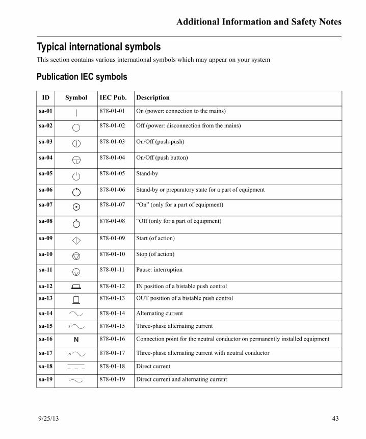
Additional Information and Safety Notes
Typical international symbolsThis section contains various international symbols which may appear on your system
Publication IEC symbols
ID Symbol IEC Pub. Description
sa-01 878-01-01 On (power: connection to the mains)
sa-02 878-01-02 Off (power: disconnection from the mains)
sa-03 878-01-03 On/Off (push-push)
sa-04 878-01-04 On/Off (push button)
sa-05 878-01-05 Stand-by
sa-06 878-01-06 Stand-by or preparatory state for a part of equipment
sa-07 878-01-07 “On” (only for a part of equipment)
sa-08 878-01-08 “Off (only for a part of equipment)
sa-09 878-01-09 Start (of action)
sa-10 878-01-10 Stop (of action)
sa-11 878-01-11 Pause: interruption
sa-12 878-01-12 IN position of a bistable push control
sa-13 878-01-13 OUT position of a bistable push control
sa-14 878-01-14 Alternating current
sa-15 878-01-15 Three-phase alternating current
sa-16 878-01-16 Connection point for the neutral conductor on permanently installed equipment
sa-17 878-01-17 Three-phase alternating current with neutral conductor
sa-18 878-01-18 Direct current
sa-19 878-01-19 Direct current and alternating current
3
N
3N
9/25/13 43

Natus Neurology Incorporated
sa-20 878-01-20 Protective Earth (ground)
sa-21 878-01-21 Earth (ground)
sa-22 878-01-22 Noiseless (clean) earth (ground)
sa-23 878-01-23 Frame or chassis
sa-24 878-01-24 Equipotentiality
sa-25 878-01-27 Plus; positive polarity
sa-26 878-01-24 Minus; negative polarity
sa-27 878-01-29 Calibration
sa-28 878-01-36 Input
sa-29 878-01-37 Output
sa-30 878-01-38 Remote control
sa-31 878-01-39 Local control
sa-32 878-01-40 Clock; time switch; timer
sa-33 878-01-41 Bell
sa-34 878-01-42 Zero point adjustment
sa-35 878-01-43 Setting to central position
sa-36 878-01-44 Hand-held switch
sa-37 878-01-45 Manual control
sa-38 878-01-59 Slow run
sa-39 878-01-60 Normal run
sa-40 878-01-61 Fast run
sa-41 878-01-62 Normal run from a limit
ID Symbol IEC Pub. Description
44 9/25/13
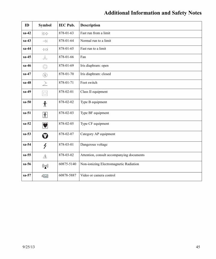
Additional Information and Safety Notes
sa-42 878-01-63 Fast run from a limit
sa-43 878-01-64 Normal run to a limit
sa-44 878-01-65 Fast run to a limit
sa-45 878-01-66 Fan
sa-46 878-01-69 Iris diaphram: open
sa-47 878-01-70 Iris diaphram: closed
sa-48 878-01-71 Foot switch
sa-49 878-02-01 Class II equipment
sa-50 878-02-02 Type B equipment
sa-51 878-02-03 Type BF equipment
sa-52 878-02-05 Type CF equipment
sa-53 878-02-07 Category AP equipment
sa-54 878-03-01 Dangerous voltage
sa-55 878-03-02 Attention, consult accompanying documents
sa-56 60875-5140 Non-ionizing Electromagnetic Radiation
sa-57 60878-5887 Video or camera control
ID Symbol IEC Pub. Description
AP
!
9/25/13 45
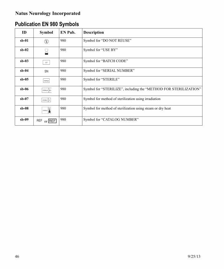
Natus Neurology Incorporated
Publication EN 980 SymbolsID Symbol EN Pub. Description
sb-01 980 Symbol for “DO NOT REUSE”
sb-02 980 Symbol for “USE BY”
sb-03 980 Symbol for “BATCH CODE”
sb-04 980 Symbol for “SERIAL NUMBER”
sb-05 980 Symbol for “STERILE”
sb-06 980 Symbol for “STERILIZE”, including the “METHOD FOR STERILIZATION”
sb-07 980 Symbol for method of sterilization using irradiation
sb-08 980 Symbol for method of sterilization using steam or dry heat
sb-09 or 980 Symbol for “CATALOG NUMBER”
2
LOT
SN
STERILE
STERILE EO
STERILE R
STERILE
REF
46 9/25/13

Additional Information and Safety Notes
Publication IEC 417 SymbolsID Symbol IEC 417 Pub. Description
sc-01 2497 Date of manufacture
sc-02 5001 Battery check
sc-03 5002 Battery position
sc-04 5004 Variability
sc-05 5004 Variability
sc-06 5012 Lamp; lighting; illumination
sc-07 5016 Fuse
sc-08 5076 Earphone
sc-09 5077 Headphones
sc-10 5078 Stereophonic headphones
sc-11 5079 Headset
sc-12 5080 Loudspeaker
sc-13 5081 Loudspeaker/microphone
sc-14 5082 Microphone
sc-15 5083 Stereophonic microphone
+
9/25/13 47

Natus Neurology Incorporated
Publication TR 60878 Symbols
Directive 2002/96/EC symbols
Miscellaneous symbols
ID Symbol TR 60878 Pub. Description
sd-01 5309 Alarm system clear
sd-02 5049 Television/Video
sd-03 5084 Amplifier
sd-04 5184 Clock (Current Time)
sd-05 5521B Video Input/Output
sd-06 5546 Battery Check (Battery Life Condition)
sd-07 1135 The packing material marked with this symbol is either recyclable, reus-able, or renewable.
sd-08 5749 Electrical Cautery Device(For use in the presence of electrical cautery device.)
ID SymbolEuropean Directive
Description
se-01 or
2002/96/EC Indicates that these products come under the provisions of EU Directive 2002/96/EC on waste electrical and electronic (WEEE) and that this uni
was placed on the market after 12th August 2005. This directive covers EOL (End Of Life) disposal.
ID Symbol Description
sf-01 or
Medical device listing mark for U.S. and Canada by Intertek Testing Service.
sf-02 CE Mark
sf-03 Caution: Federal law in the U.S.A. and Canada restricts the sale, distribution or use of this device to, by or on the order of a licensed medical practitioner.
sf-04 Latex free.
Rx
48 9/25/13

Additional Information and Safety Notes
Typical symbols on Nicolet Brand systemsFollowing are typical symbols which may appear accordingly on a variety of Nicolet Brand systems.
ID Symbol Description
sya-01 Headphones
sya-02 Stimulator Module In
sya-03 Stimulator Module Out
sya-04 Mouse
sya-05 Mouse
sya-06 Remote LEDs
sya-07 Parallel/Printer
sya-08 Com Port (1 or 2)
sya-09 Microphone
sya-10 Audio In
sya-11 Audio Out
sya-12 Ganzfeld
sya-13 Speaker
sya-14 Control Panel
sya-15 Footswitch
sya-16 Trig 1 Out
sya-17 Trig 2 Out
sya-18 Trigger In
sya-19 LED Goggles
sya-20 Speaker/Trigger Outputs
sya-21 Electrical Stimulator Box
1 2 3 4
10101 or 01010
10101 or 101011 2
or
or
1 1
2 2
1
9/25/13 49

Natus Neurology Incorporated
sya-22 Video (monitor)
sya-23 Current (Amperes)
sya-24 Hertz (Frequency) or Pulse Frequency
sya-25 System power (Watts)
sya-26 Volt-Amperes
sya-27 Reflex Hammer
sya-28 Amplifier
sya-29 Photic Strobe
sya-30 Headbox Check
sya-31 Amplifier Interface
sya-32 USB
sya-33 Network
sya-34 Joy Stick
sya-35 Input
sya-36 Output
sya-37 1394 Firewire
sya-38 Mute
sya-39 Stimulator (electrical)
sya-40 Serial Port Connection
sya-41 Variability
sya-42 Stimulator (electrical)
sya-43 Electrostatic Sensitive
sya-44 Keyboard
sya-45 Non Isolated Output
ID Symbol Description
A
Hz
W
VA
AmplifierInterface
1394
Non IsolatedOutput
50 9/25/13

Additional Information and Safety Notes
sya-46 Not for patient environment
sya-47 Temperature Probe
sya-48 Laptop Computer
sya-49 Label only NON-ISOLATED SIGNAL INPUTSThe signal inputs are not isolated.
sya-50 Television/Video Control
sya-51 Disk Storage Remaining
sya-52 Storage Media
sya-53 Recording Time
sya-54 On/Off/Patient Event/Backlight/Refresh
sya-55 Not for use in Operating Room
sya-56 Reference (red oval)
sya-57 Ground (green oval)
sya-58 Impedance check On/Off
sya-59 Transmitting data
sya-60 SYNC Trigger Synchronization
sya-61 Isolated Stimulation Outputs IOM
sya-62 Remote Start/Stop
sya-63 Train Duration
sya-64 Nonin Xpod Pulse Oximeter Input
sya-65 Power Supply Input
sya-66 Video Composite 1
sya-67 Video Composite 2
sya-68 Headbox Input
sya-69 Yoke Patient Neck Yoke Input
ID Symbol Description
MB
SpO2
PSU-v32
1
2
9/25/13 51

Natus Neurology Incorporated
sya-70 Aux I/O Auxiliary Input/Output
sya-71 DC1 - DC12 DC Inputs 1 through 12
sya-72 Power On
sya-73 Check that correct channels (electrodes) have been connected to the amplifier.
sya-74 Display stimulation level being delivered.
sya-75 &
Select which channels (electrodes) will receive the stimulus.
sya-76 Ictal Disrupt. Initiate a single stimulus pulse.
sya-77 Mark ID tags before and after stimulation.
sya-78 Length of time for each pulse.
sya-79 Pulse frequency.
sya-80 Set the current level applied to the patient.
sya-81 Change Nicolet Cortical Stimulator Control Unit parameters.
sya-82 Start. Deliver stimulation pulse.
sya-83 Current status of the Nicolet Cortical Stimulator.
sya-84 Stop. Interrupt Train or Continuous stimulation.
sya-85 View the present maximum stimulus duration (Nicolet Cortical Simulator).
sya-86 Do not tilt more than 5 degrees.
sya-87 Pinching hazard.
sya-88 Stimulation on.
sya-89 Stimulation on.
sya-90 Battery test.
sya-91 Input/output option device port.
ID Symbol Description
5° 5°
5° 5°
+ TEST
52 9/25/13

Additional Information and Safety Notes
sya-92 Consult Operating Instructions. Failure to follow operating instructions could place the patient or operator at risk. Image on blue background. (ISO 7010 M002)
sya-93 Direct Current input.
sya-94 Not for use in the presence of electrical cautery device without additional patient protec-tion headbox or other in-line protection device.
sya-95 Next Exam
sya-96 Select Exam
sya-97 EMG Exam
sya-98 Nerve Conduction Study Exam
sya-99 Change time base
sya-100 Change amplitude
sya-101 Enter
sya-102 Print
sya-103 Notepad
sya-104 Average
sya-105 User-definable
sya-106 User-definable
sya-107 Set Markers
sya-108 Trace up (for Synergy, icon is for Next Trace only)
sya-109 Trace down (for Synergy, icon is for Next Trace only)
sya-110 Set Markers
sya-111 Decrease Duration
sya-112 Increase Duration
sya-113 Erase waveform (for EDX, also Backspace)
ID Symbol Description
9/25/13 53

Natus Neurology Incorporated
sya-114 Input measurements (activates numbers on number pad)
sya-115 Start/stop stimulus
sya-116 Recurrent stimulus
sya-117 Stimulus intensity (for Stim A on Synergy)
sya-118 Speaker volume
sya-119 Battery level indicator
sya-120 Never tilt or incline the cart backward more than 5°.
sya-121 Aways lower the height adjustable keyboard and monitor before moving the cart.
sya-122 Reflex Hammer.
sya-123 Input/output option device port.
sya-124 Viking Control Panel.
sya-125 Trigger 1 / 2 Out.
sya-126 Analog Out.
sya-127 Attention, consult accompanying documents.
sya-128 Audio Out.
sya-129 Type BF Equipment.
sya-130 Audio In.
sya-131 Electrostatic Sensitive.
sya-132 Loudspeaker.
sya-133 Equipotentiality.
sya-134 Footswitch for single switch only.
ID Symbol Description
2
!
or
or
54 9/25/13

Additional Information and Safety Notes
sya-135 Amplifier.
sya-136 USB.
sya-137 Trigger 1 / 2 In.
sya-138 Trigger.
sya-139 Stimulator Option Port.
sya-140 R Right ear headphone Out.
sya-141 Headphones.
sya-142 L Left ear headphone Out.
sya-143 System Power.
sya-144 Output Power.
sya-145 AC Power.
sya-146 Fuse.
sya-147 HZ Frequency Range.
sya-148 VA System Power / Output Power
sya-149 Attention, consult accompanying documents.
sya-150 - To (Touch-proof) Electrical Stimulator. Positive Output.
sya-151 IES-1 Isolated Electrical Stimulator 1 (- / +).
sya-152 + To (Touch-proof) Electrical Stimulator. Negative Output.
sya-153 Attention, consult accompanying documents.
sya-154 IES-2 Isolated Electrical Stimulator 2 (- / +).
sya-155 Electrical Stimulator.
sya-156 Type BF Equipment.
sya-157 On (part of a system).
sya-158 Stimulation On/Off.
sya-159 Stimulation On/Off.
ID Symbol Description
!
!
9/25/13 55
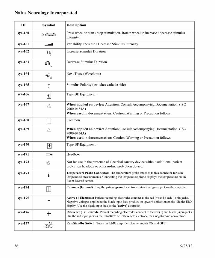
Natus Neurology Incorporated
sya-160 Press wheel to start / stop stimulation. Rotate wheel to increase / decrease stimulus intensity.
sya-161 Variability. Increase / Decrease Stimulus Intensity.
sya-162 Increase Stimulus Duration.
sya-163 Decrease Stimulus Duration.
sya-164 Next Trace (Waveform)
sya-165 +-
Stimulus Polarity (switches cathode side)
sya-166 Type BF Equipment.
sya-167 When applied on device: Attention: Consult Accompanying Documentation. (ISO 7000-0434A)When used in documentation: Caution, Warning or Precaution follows.
sya-168 Common.
sya-169 When applied on device: Attention: Consult Accompanying Documentation. (ISO 7000-0434A)When used in documentation: Caution, Warning or Precaution follows.
sya-170 Type BF Equipment.
sya-171 Headbox.
sya-172 Not for use in the presence of electrical cautery device without additional patient protection headbox or other in-line protection device.
sya-173 Temperature Probe Connector: The temperature probe attaches to this connector for skin temperature measurements. Connecting the temperature probe displays the temperature on the Exam Record screen.
sya-174 Common (Ground): Plug the patient ground electrode into either green jack on the amplifier.
sya-175 - Active (-) Electrode: Patient recording electrodes connect to the red (+) and black (-) pin jacks. Negative voltages applied to the black input jack produce an upward deflection on the Nicolet EDX display. Use the black input jack as the ’active’ electrode.
sya-176 + Reference (+) Electrode: Patient recording electrodes connect to the red (+) and black (-) pin jacks. Use the red input jack as the ’inactive’ or ’reference’ electrode for a negative-up convention.
sya-177 Run/Standby Switch: Turns the EMG amplifier channel inputs ON and OFF.
ID Symbol Description
!
!
56 9/25/13

Additional Information and Safety Notes
sya-178 Headbox Connector: For optional HB-6 Headbox.
sya-179 1020 Integrated Headbox: 1020 Integrated Headbox.
ID Symbol Description
9/25/13 57

Natus Neurology Incorporated
Example Nicolet Brand labelsFollowing are example labels used with various Nicolet Brand systems.
ID Label Description
lba-01 Connect it to BMSI Patient Amplifier only to guard against damage to the item and/or system.
lba-02 Connect it to BMSI isolation box only to guard against damage to the item and/or system.
lba-03 Face the camera forward while moving the cart to avoid damaging the camera.
lba-04 Hold the camera while making camera adjustments to avoid damaging the camera.
lba-05 To guard against serious injury or damage to the instrument, only quali-fied service personnel should remove the cover. Disconnect all power before removal.
lba-06 Connect device to Patient Amplifier only to guard against damage to the device and/or system.
lba-07 Connect device to isolation box only to guard against damage to the device and/or system.
lba-08 To guard against serious injury or damage to the instrument, do not use in the presence of flammable anesthetics.
lba-09 To avoid serious injury or damage to the instrument, connect the device only to a properly grounded outlet. All transcranial doppler diagnostic external cables must be EME authorized.
lba-10 Replace bad fuses with fuses of the same type and rating to guard against risk of fire or damage to the device.
WARNING!
For use with BMSIPatient Amplifier only.
WARNING!
For use with BMSIisolation box only.
CAUTION!
To avoid cameradamage, face camera forwardwhile moving cart.
CAUTION!
To avoid cameradamage, do notmake camera adjustments without firstsupporting itsweight.
CAUTION!
Electrical shock hazardDO NOT REMOVE COVER
Refer servicing toqualified personnel.
WARNING!
For use with NicoletPatient Amplifier only.
WARNING!
For use with Nicoletisolation box only.
DANGER!
Possible EXPLOSION hazardif used in the presence offlammable anesthetics.
WARNING !
Connect only to a properly earth grounded outlet.
All external cables and units must be EME authorized.
CAUTION!
For continued protectionagainst risk of fire,replace fuse(s) with sametype and rating.
58 9/25/13

Additional Information and Safety Notes
lba-11 Connect device to Patient Amplifier only to guard against damage to the device and/or system.
lba-12 Connect device to Patient Amplifier only to guard against damage to the device and/or system.
lba-13 Connect device to Patient Amplifier only to guard against damage to the device and/or system.
lba-14 Use caution when using the S403 stimulus probe. Make sure the inten-sity is turned all way off (minimum output) before applying to patient to guard against discomfort or injury.
lba-15 Connect to a Hospital Grade receptacle only to help ensure grounding reliability.
lba-16 Use only a 115 VAC power source in the US and Canada.
lba-17 Identifies a Class 1 Laser Product.
lba-18 V44 amplifier hot surface warning.
ID Label Description
CAUTION!
Power connectors are intended only forNicolet approved system components.Use of any other equipment could resultin damage to the power system.
CAUTION!
Power connectors are intended only forCareFusion approved system components.Use of any other equipment could resultin damage to the power system.
WARNING!
Power connectors are intended only forVIASYS NeuroCare approve systemcomponents. Use of any otherequipment could result in damageto the power system.
WARNING!
Hazardous electrical output.This equipment is for use onlyby qualified personnel.
ATTENTIONGROUNDING RELIABILITY CAN ONLY BE ACHIEVED
WHEN THIS EQUIPMENT IS CONNECTED TO ARECEPTACLE MARKED "HOSPITAL GRADE."
! US and Canada use only 115 VAC
CLASS 1 LASER PRODUCT
CAUTION:Hot surface
9/25/13 59

Natus Neurology Incorporated
Example Nicolet Brand voltage labelsFollowing are example voltage labels used with various Nicolet Brand systems.
ID Label Description
vla-01 Non isolated outputInput voltage of 100 or 115VAC at 50 or 60 HertzMaximum total output power is 100VA
vla-02 Non isolated outputInput voltage of 230VAC at 50 or 60 HertzMaximum total output power is 100VA
vla-03 Output voltage of 100 or 115VAC at 50 or 60 HertzMaximum total output power is 500VA
vla-04 Output voltage of 230VAC at 50 or 60 HertzMaximum total output power is 500VA
vla-05 Input voltage of 100 or 115VAC at 50 or 60 HertzMaximum total output power is 595VA
vla-06 Input voltage of 230VAC at 50 or 60 HertzMaximum total output power is 595VA
vla-07 Input voltage of 100, 115 or 230VAC at 50 or 60 HertzMaximum total output power is 500VA
60 9/25/13

Additional Information and Safety Notes
vla-08 Input voltage of 100, 120 or 230VAC (110VA) at 50 or 60 HertzMaximum total output power is 70VA
vla-09 Output voltages of 100, 120, or 230VAC
ID Label Description
9/25/13 61

Natus Neurology Incorporated
62 9/25/13

Index
AAmplifier arm 15Amplifiers 24Auditory stimulator for Nicolet EDX, Nicolet
Endeavor, Nicolet VikingSelect, Nicolet VikingQuest, Synergy Focus and Synergy Plinth 18
BBatteries 21Bovie / Electrocautery 19
CCaution label definition 3CE Mark 2Cleaning, disinfection and sterilization of parts in
contact with the patient 7
DData Corruption 13Data false negatives 13Data false positives 13Data loss 13Data misinterpretation 13Defibrillation 22Directive 2002/96/EC symbols 48Disposal 21
EElectrical shock (line voltage) 12Electrical stimulators for Nicolet EDX, Nicolet
Endeavor, Nicolet VikingSelect, Nicolet VikingQuest, Synergy Focus and Synergy Plinth and PIU 17
Electrocautery 19Electrodes and Amplifiers 24Electrodes and transducers 15EMC 27EMG 20Ergonomic Environment Responsibilities 5ESD handling 28European Authorized Representative 2
FFuses 22
GGeneral safety notes 9
HHard drive 22
IIdentifiers
aa-01 6ab-01 7ac-01 9ad-01 12ae-01 13af-01 15ag-01 15ah-01 15ai-01 17aj-01 18ak-01 19al-01 20am-01 20an-01 20ao-01 21ap-01 21aq-01 22ar-01 22as-01 22at-01 22au-01 23av-01 24aw-01 25ax-01 26ay-01 27az-01 28ba-01 29bb-01 30bc-01 31da-01 33db-01 36dc-01 37dd-01 39de-01 39df-01 40lba-01 58
9/25/13 1

Natus Neurology Incorporated
sa-01 43sb-01 46sc-01 47sd-01 48se-10 48sf-01 48sya-01 49vla-01 60
Implant electrodes 20Isolation / Isolation transformer 25Isolation transformer 25
LLeakage current 20, 22
MMains operated equipment with additional power
supply 22Manufacturer 2Miscellaneous symbols 48
NNetworking 29Nicolet 2015 Visual Stimulator 39Nicolet Ambulatory EEG 39Nicolet Brand labels 58Nicolet Brand voltage labels 60Nicolet cEEG 33Nicolet EDX 17, 18, 37Nicolet Endeavor 17, 18, 36Nicolet Endeavor CR 36Nicolet Monitor 33Nicolet nEEG / LTM 33Nicolet vEEG 33Nicolet VikingQuest 17, 18, 37Nicolet VikingSelect 17, 18, 37NONIN Pulse Oximeters 40
OOperating environment 30
PPhysical injury 15Preventive maintenance 6
Product Specific Cautions and Warnings 33Protective packaging measures 23Publication EN 980 Symbols 46Publication IEC 417 Symbols 47Publication IEC symbols 43Publication TR 60878 Symbols 48Pulse duration 18Pulse width 9, 18
RRecycling 21Replacement of fuses and other parts 22Restricted environmental conditions for operation,
transport and storage 23
Ssafety
EMC 27Safety notes 9Safety Summary 3Service manuals for your system 4Shipping conditions 23Software 26Specifications Nicolet Brand systems 5Stimulation pulse terminology 18Storage 23Synergy Plinth 18Synergy Plinth and PIU 17, 37System connections 31
TTechnical support 2Transducers 15Transport 23Typical international symbols 43Typical symbols on Nicolet Brand systems 49
UU.S. Patents 3UltraPro S100 17, 18, 37
WWarning label definition 3
2 9/25/13